electronic spark timing (est) ignition system ignition system description—3.0...
TRANSCRIPT

Ignition System
90-899883197 AUGUST 2011 Page 4C-1
4C
Electrical SystemSection 4C - Ignition System
Table of Contents
Exploded View—Distributor and Related Components.....4C-4Precautions........................................................................4C-2Timing Specifications.........................................................4C-6
3.0 TKS.......................................................................4C-63.0 MPI ECT...............................................................4C-6
Spark Plug Specifications..................................................4C-73.0 TKS.......................................................................4C-73.0 MPI ECT...............................................................4C-7
3.0 Four‑Cylinder In‑Line Firing Order...............................4C-7Ignition System—3.0 MPI ECT..........................................4C-7
Ignition System Description—3.0 MPI ECT................4C-7Propulsion Control Module (PCM)..............................4C-7
Ignition System—3.0 TKS..................................................4C-8Ignition System Description—3.0 TKS.......................4C-8Electronic Spark Timing (EST) Ignition System
Operation—3.0 TKS ...............................................4C-9Spark Plugs.....................................................................4C-11
Removal...................................................................4C-11Cleaning and Inspection...........................................4C-11Installation................................................................4C-12
Spark Plug Wires.............................................................4C-12Removal...................................................................4C-12Inspection.................................................................4C-12Installation................................................................4C-12
Ignition Coil......................................................................4C-12Removal...................................................................4C-12Inspection and Testing.............................................4C-13Installation................................................................4C-13
Distributor........................................................................4C-14Removing the Distributor..........................................4C-14Distributor Disassembly............................................4C-16Cleaning and Inspecting...........................................4C-16Distributor Assembly.................................................4C-16Installing the Distributor ...........................................4C-17
Distributor Component Testing—3.0 TKS.......................4C-19General Information..................................................4C-19Testing the Ignition Module......................................4C-19Testing the Pickup Coil.............................................4C-19
Ignition Timing—3.0 TKS.................................................4C-19

Ignition System
Page 4C-2 90-899883197 AUGUST 2011
Precautions! WARNING
Avoid fire or explosion hazard. Electrical, ignition, and fuel system components on Mercury Marine products comply withfederal and international standards to minimize risk of fire or explosion. Do not use replacement electrical or fuel systemcomponents that do not comply with these standards. When servicing the electrical and fuel systems, properly install andtighten all components.
! WARNINGNeglect or improper maintenance, repairs, or inspections of the power package can result in product damage or serious injuryor death. Perform all procedures as described in this manual. If you are not familiar with proper maintenance or serviceprocedures, consign the work to an authorized Mercury Marine dealer.
! WARNINGPerforming service or maintenance without first disconnecting the battery can cause product damage, personal injury, ordeath due to fire, explosion, electrical shock, or unexpected engine starting. Always disconnect the battery cables from thebattery before maintaining, servicing, installing, or removing engine or drive components.
! WARNINGExplosive fumes contained in the engine compartment can cause serious injury or death from fire or explosion. Beforestarting the engine, operate the bilge blower or vent the engine compartment for at least five minutes.
! WARNINGFuel is flammable and explosive. Ensure that the key switch is off and the lanyard is positioned so that the engine cannotstart. Do not smoke or allow sources of spark or open flame in the area while servicing. Keep the work area well ventilatedand avoid prolonged exposure to vapors. Always check for leaks before attempting to start the engine, and wipe up anyspilled fuel immediately.
NOTICEWithout sufficient cooling water, the engine, the water pump, and other components will overheat and suffer damage. Providea sufficient supply of water to the water inlets during operation.
IMPORTANT: To avoid damaging the electrical system, follow these precautions:• Do not tap accessories into the engine harness.• Do not puncture wires for testing (probing).• Do not reverse the battery leads.• Do not splice wires into the harness.• Do not attempt diagnostics without the proper, approved service tools.
Lubricants, Sealants, AdhesivesTube Ref No. Description Where Used Part No.
Silicone dielectriccompound Coil high-tension lead tower
25 Liquid Neoprene High tension wire coil tower 92- 25711 3
154
Mercury MerCruiser Full-Synthetic Engine Oil20W-40, NMMA FC-Wrated
Distributor shaft 92-858087K01

Ignition System
90-899883197 AUGUST 2011 Page 4C-3
Special Tools
Computer Diagnostic System (CDS G3) Order from SPX
4520
Monitors all electrical systems for proper function, diagnostics, and calibrationpurposes. For additional information, pricing, or to order the ComputerDiagnostic System G3 contact:SPX Corporation28635 Mound Rd.Warren, MI 48092or call:USA ‑ 1‑800‑345‑2233Canada ‑ 800‑345‑2233Europe ‑ 49 6182 959 149Australia ‑ (03) 9544‑6222
Timing Light 91‑ 99379
11561
Allows a technician to check ignition timing.
Service Tachometer/Dwell Meter 91‑ 59339
F
. E
13472
Aids in checking engine RPM (0‑10,000); also checks the dwell on breaker pointignition systems.

Ignition System
Page 4C-4 90-899883197 AUGUST 2011
Exploded View—Distributor and Related Components
46828
2
3
7
1
6
6
8
8
5
15
17
18
14
4
9
10
11
13
12
19
16

Ignition System
90-899883197 AUGUST 2011 Page 4C-5
Exploded View—Distributor and Related ComponentsRef. No. Qty. Description
1 1 Distributor—complete assembly2 1 Cap3 1 Rotor4 1 Module5 2 Screw6 1 Coil piece7 1 Shaft assembly8 1 Pole piece9 1 Gear
10 1 Roll pin11 1 Gasket12 1 Hold‑down clamp13 1 Screw14 1 Spark plug wire (represents 1 set)15 4 Spark plug (represents 1 set)16 1 Plug wire retainer17 1 Ignition coil18 2 Screws19 1 Harness assembly

Ignition System
Page 4C-6 90-899883197 AUGUST 2011
Timing Specifications3.0 TKSTiming at Idle RPM
Timing (at idle rpm)¹Serial number break: 0L341000 and above. 2° ATDC
¹:Timing must be set using a special procedure as outlined in this section. Timing cannot be properly set using theconventional method.
Timing Advance Curve and RPMIMPORTANT: Advance curve includes initial timing. Do not add initial timing degrees to the total advance degrees.
a - Total spark advanceb - Engine RPMc - Maxiumumd - Minimum
3.0 MPI ECTTiming (at idle rpm)Serial number: All models Not adjustable
a
b
d
c
48013

Ignition System
90-899883197 AUGUST 2011 Page 4C-7
Spark Plug Specifications3.0 TKS
Spark plug gap 1.14 mm (0.045 in.)
Spark plug typeAC‑MR43LTS
NGK‑BPR6EFSChampion RS12YC
3.0 MPI ECTSpark plug gap 1.14 mm (0.045 in.)
Spark plug typeAC MR43LTS
Champion RS12YCNGK BPR6EFS
3.0 Four‑Cylinder In‑Line Firing Order
47960
3.0 firing order: 1—3—4—2
Ignition System—3.0 MPI ECTIgnition System Description—3.0 MPI ECT
When the ignition key switch is turned to the "RUN" position, battery voltage is applied to both the PCM and the main powerrelay (MPR) through the wiring. As the PCM receives the "RUN" signal, it internally completes the ground circuit of the mainrelay for a period of two seconds, energizing the ignition/injection systems for start‑up. As the engine is cranked with the startermotor, the PCM receives the run signal from the crank position sensor (CPS) and completes the ground circuit to the main relayfor engine operation.With the main relay closed (completed circuit), D.C. current from the battery/charging system is transferred through the 20‑ampmain relay fuse to the positive terminal of the ignition coil primary windings. The negative terminal of the ignition coil primary isconnected to the engine ground through the coil's internal driver, which is triggered by the PCM. With the coil driver closed, anelectric magnetic field is allowed to build up within the ignition coil.As the crankshaft pulley‑mounted trigger wheel rotates, the CPS senses the location of the teeth and supplies the trigger signalinformation to the PCM. The PCM utilizes the CPS information and determines when to remove the trigger signal from the coildriver of the ignition coil. The coil driver then opens the coil primary ground circuit which allows its magnetic field to rapidlycollapse across the coil secondary winding, which induces a high‑voltage charge (50,000 volts) that fires the spark plugs. Thedistributor rotor distributes the spark to each cylinder in firing order through the distributor cap and plug wires.
Propulsion Control Module (PCM)The PCM requires 8 VDC minimum to operate. If the PCM should fail, the engine will stop running. Some inputs to the PCMcan be monitored and tested using the computer diagnostic system (CDS).NOTE: The model year 2004 PCM software does not support ignition load tests.
Computer Diagnostic System (CDS G3) Order from SPX
The PCM controls the following functions:

Ignition System
Page 4C-8 90-899883197 AUGUST 2011
• Calculates the precise fuel and ignition timing requirements based on engine speed, throttle position, manifold pressure,manifold air temperature, and cylinder block coolant temperature.
• Directly controls the ground circuit to: fuel injectors, direct injectors, ignition coil driver, main power relay activation,diagnostics, engine guardian, tachometer link (analog tachometer output or link gauge driver).
• Indirectly controls the positive circuit to: fuel injectors, ignition coils, main power relay activation.
When the key switch is moved to the "RUN" position, but the engine is not started, the PCM completes the ground circuit for themain power relay and a 5 VDC reference to the engine sensors. The PCM monitors engine sensors, SmartCraft vesselsensors, and will transmit fault information from these sensors to the helm. Once the engine has started, the PCM controls andmonitors all engine functions.
Ignition System—3.0 TKSIgnition System Description—3.0 TKS
EST or Electronic Spark Timing is a high energy ignition system (HEI). The distributor has no centrifugal advance mechanismor devices.The spark plug wires are carbon‑impregnated cord conductors with silicone rubber jackets. It is important that they be handledwith care and routed so as not to cross each other or to be in contact with other parts of the engine to prevent rubbing.The EST System uses a square coil with epoxy covered windings to protect against moisture and arc‑over.The timing cannot be set the same way as other ignition systems.
a - Distributor with spark plug wiresb - White wires (used in timing procedure)—TKSc - Wire from shift interrupt switch—TKSd - Distributor harness—TKSe - Engine harness wire (purple and gray)f - Coilg - Distributor harness—MPIh - White wires—MPIi - Wire from shift interrupt switch—MPI
EST uses a magnetic pulse generator and an electronic module to generate primary circuit current. Internally, the pulsegenerator, or magnetic pick‑up assembly, takes the place of conventional points. A timer core on the main shaft of thedistributor has external teeth that align with an equal number of pole piece teeth (four for a four‑cylinder engine). The electronicmodule is small enough to allow it to be mounted inside the distributor and contains the circuits necessary for dwell control andadvance of the timing.
a
bbc
d
ee
f
bh
i
g
47961

Ignition System
90-899883197 AUGUST 2011 Page 4C-9
Molded into the module is a two‑pin connector (for the distributor harness that attaches to the coil terminals) and a four‑pinconnector. Only three of the four terminals of the second connector are used by MerCruiser (one wire for the shift interrupt andtwo white wire leads, on TKS models, are used to "freeze" advance for properly setting initial timing). Inside the distributor, thepick‑up coil attaches to the module with a molded connector.
a - External teethb - Pole piece teethc - Magnetic pulse generatord - Pick‑up coil connectore - Four‑pin connectorf - Two‑pin connectorg - Electronic moduleh - Timer core
Electronic Spark Timing (EST) Ignition System Operation—3.0 TKSTo provide primary current for the ignition coil, EST uses a magnetic pulse generator and an electronic module. The pulsegenerator consists of a timer core on the main distributor shaft and a pole piece around the outside. The magnetic pole piece isdesigned with the same number of internal teeth as engine cylinders (four‑cylinder engines = four teeth). The timer core rotatesinside of the pole piece and has an equal number of external teeth. As the internal and external teeth start to align, voltageoutput from the magnetic pickup coil increases, and as the teeth align and pass each other, the voltage reverses polarity anddecreases. As the distributor shaft rotates, the pickup assembly produces AC voltage.
42949
Distributor Assembly (4 cyl. shown)
Ignition Control Module - Engine RunningTo help understand how EST circuits operate, a relay with a double set of contact points is shown. Solid‑state circuitry is usedin the module, but adding the relay makes it easier to visualize. On the 3.0 TKS models with the engine running the relay is inthe de‑energized state. This connects the pickup coil to the base of the transistor. The voltage output from the magnetic pickupassembly is used to turn the transistor in the module on and off. A transistor has polarity, so as a result, it turns on like a switch,but only when the polarity is correct to flow through in one direction only. When the time core teeth start to approach the polepiece teeth, voltage rises closing the transistor and allowing current to flow through the primary ignition coil to ground. As thepole pieces align and pass, the polarity of the pickup voltage begins to reverse. As the polarity reverses, the transistor will turnoff, causing the current to stop flowing through the primary ignition coil windings. The moment the transistor is turned off, aspark occurs in a cylinder.
a
c
d
g
b
ef
h
47964

Ignition System
Page 4C-10 90-899883197 AUGUST 2011
The length of time there is current flowing through the coil is called dwell. Dwell is measured in terms of degrees of distributorrotation. As the engine RPM increases, the time available for dwell is decreased, causing the secondary (coil) output todecrease. To help reduce the effect of decreased secondary output, as engine RPM increases the dwell increases by startingthe ground path of the primary ignition coil earlier, so as not to affect ignition timing. The module monitors the amperagerequired by the ignition coil and alters start of the ground path.
42951
Ignition control module—engine running

Ignition System
90-899883197 AUGUST 2011 Page 4C-11
Ignition Control Module - Timing BypassSince advance will occur below 1000 RPM, the advance must be disabled before attempting to set initial timing. On the 3.0TKS models, bypassing the interrupter switch energizes the relay, causing the points from the pickup coil as well as thegrounding points to open. By connecting a jumper between the white wires from the distributor, a pulse is pulled from the signalconverter and routed to the transistor. This bypasses the timer circuit and disables the advance.
42950
Ignition control module—timing bypass
Spark PlugsRemoval
1. Remove the spark plug wires. Note the location for reinstallation.2. Clean any dirt or debris around the spark plug.3. Remove the spark plugs.
Cleaning and Inspection1. Inspect each plug for worn electrodes and glazed, broken or blistered porcelain. Replace any excessively worn or
damaged plugs.
a - Porcelain insulatorb - Side electrode (gap adjusting)c - Proper gapd - Center electrode (flat tip)e - Shellf - Check for cracks in porcelain in this area
2. Use a solvent to clean any deposits from the electrode or porcelain.3. Check the type of spark plug. Replace spark plugs that are the incorrect type. Refer to Spark Plug Specifications.4. Check the gap of the spark plugs with a round feeler gauge. Adjust if necessary. Refer to Spark Plug Specifications.
ab
ce
df
47970

Ignition System
Page 4C-12 90-899883197 AUGUST 2011
InstallationIMPORTANT: Tapered seat spark plugs are not interchangeable with non‑tapered spark plugs. Do not use gaskets on taperseat plugs.1. Clean the spark plug seating area.2. Install the spark plugs and tighten to specification.
Description Nm lb‑in. lb‑ftSpark plugs 30 – 22
Spark Plug WiresRemoval
NOTE: Use care when removing the spark plug wires and the boots from the spark plugs.1. Label the spark plug wires and locations for reinstallation.2. Twist the boot one‑half turn before removing the spark plug wire.3. Firmly grasp and pull on the boot and wire to remove the wire.
Inspection1. Visually inspect the spark plug wires and the coil wire for damage.2. Visually inspect the spark plug boots for damage.3. Check the spark plug wires and the coil wire for continuity using a multimeter. Replace any wires that do not show
continuity from end to end.4. Replace any wires that are cracked, cut, or have damaged spark plug boots.
InstallationIMPORTANT: Only use spark plug wires recommended for marine applications.NOTE: Replace one spark plug wire at a time to reduce the risk of routing error.1. Disconnect each individual spark plug wire as it is to be replaced.2. Install the replacement spark plug wires in the proper order. Observe the following:
a. Reinstall the wires in the spark plug wire retainers.b. Attach the plug wires to the appropriate spark plug and terminal on the distributor cap. Each end should fit securely.
3. Apply sealant to the outside of the high tension wire coil tower. Insert the coil wire (high tension lead) to center terminal ondistributor cap, push the boot down over the coil tower, and wipe off excess sealant.
Tube Ref No. Description Where Used Part No.
25 Liquid Neoprene High tension wire coil tower 92- 25711 3
NOTE: Ensure that the boot on the high tension wire does not come loose when pushing the wire into the terminal.
Ignition CoilRemoval
1. Detach the connectors for the engine harness and distributor from the ignition coil.2. Remove the high tension coil lead.

Ignition System
90-899883197 AUGUST 2011 Page 4C-13
3. Remove the coil bracket screws and bracket with the ignition coil.
3.0 TKS ignition coil and relateda - Coil leadb - Connector (to engine harness)c - Ignition coild - Bracket screwe - Connector (to distributor)
3.0 MPI ECa - Bracket screwb - Connector (to distributor)c - Connector (to engine harness)
Inspection and Testing1. Disconnect the wiring from the ignition coil. Connectors are molded and keyed to assure proper positioning.2. Set ohmmeter to "Rx100" scale and connect one lead to 12‑volt terminal (+) of the coil and the other lead to ground (–),
such as any clean metal on the coil frame. The reading should be infinite (no continuity). If not, replace the coil.3. Set the ohmmeter to "Rx100" scale and connect to the 12 volt terminal (+) and the distributor trigger signal (‑) terminal.
Reading should be approximately 0.4 ohms. If not, replace coil.4. Set the ohmmeter to "Rx1" scale and connect to the12‑volt terminal (+) and the tachometer terminal. Reading should be
approximately 0.4 ohms. If not, replace coil.5. Set the ohmmeter to "Rx100" high scale. Connect the ohmmeter to the 12‑volt terminal (+) and to the coil high‑tension
post. Reading should be between 7800 and 8800 ohms. If it reads outside of this range, replace the coil.
a - High‑tension postb - 12 volt (+)c - Tachometerd - Trigger signal (‑) from distributore - Filtered power (+) to distributor
NOTE: During installation, first install the black connector (distributor harness) to the coil. Install the gray connector (engineharness) last.
Installation1. Install the ignition coil and bracket to the engine bracket. Tighten the two screws to specification.
a
b
cdd
46846
e
a
46845
a
b
c
a
47915
c
b
d
e

Ignition System
Page 4C-14 90-899883197 AUGUST 2011
Description Nm lb‑in. lb‑ftIgnition coil mounting screw 24 – 18
IMPORTANT: The coil on these models produces an extremely high‑energy spark. Special steps are required to seal thecoil wire (high‑tension lead) to the coil to avoid corrosion and misfiring.
2. Apply approximately 1/2‑oz. of the specified sealant around the top of the coil high‑tension lead tower. Ensure that thesealant is not applied inside the coil high‑tension lead tower.
Tube Ref No. Description Where Used Part No.Silicone dielectriccompound Coil high-tension lead tower
3. Connect the high‑tension coil lead.IMPORTANT: When reconnecting or installing the coil, first attach the black connector (distributor harness) to the coil.Then, attach the gray connector (from engine harness) to the coil.
4. Attach the distributor wire harness connector (black) and then, the engine harness connector (gray) to the ignition coil.
3.0 MPI ECa - Bracket screwb - Black connector (to distributor)c - Gray connector (to engine harness)
3.0 TKS ignition coil and relateda - Coil lead—similar on 3.0 MPI ECb - Gray connector (to engine harness)c - Ignition coild - Bracket screwe - Black connector (to distributor)
DistributorRemoving the Distributor
1. Lift the locking tabs and remove the two‑pin and four‑pin connector from the distributor.
MPI engine shown—TKS similara - Two‑pin connectorb - Locking tabsc - Four‑pin connector
a
46845
a
b
c
a
b
cdd
46846
e
47972
b
ca
b

Ignition System
90-899883197 AUGUST 2011 Page 4C-15
2. Remove the coil and spark plug wires from the distributor cap.3. Scribe an in‑line mark on the distributor body and the engine block for reference.4. Remove the hold‑down clamp and screw.
a - Hold‑down clampb - Screw
5. Lift the distributor up and out of its position in the engine block. To assist in installation, note the orientation of theslotted‑shaft.
a - Distributorb - Slotted‑shaftc - Position in block
6. Loosen the two screws retaining the distributor cap.
47978
Distributor cap screws
7. Remove the distributor cap.
a
bb
a47976
47977
a
b
c

Ignition System
Page 4C-16 90-899883197 AUGUST 2011
8. Remove the rotor.
a - Moduleb - Screwc - Connectord - Timer coree - Rotorf - External teethg - Pole piece teethh - 4‑Pin connectori - 2‑Pin Connector
Distributor Disassembly1. Remove the rotor from the distributor shaft.2. Disconnect the coil piece wiring from the module.3. Loosen the two screws and remove the module from the distributor housing.4. Remove roll pin, washer (if equpped), and drive gear from distributor shaft using a center punch and light hammer.
Typicala - Shaftb - Punchc - Roll pin
5. Remove the distributor shaft from the housing.6. Remove the coil piece and pole piece.7. Check for side play between shaft and distributor housing bushings.
DistributorShaft‑to‑housing side play 0.05 mm (0.002 in.) Maximum
8. Check the distributor shaft runout with a dial indicator and V‑blocks.
DistributorShaft runout 0.05 mm (0.002 in.) Maximum
Cleaning and Inspecting1. Clean the cap with a solution of warm soap and water. Dry with compressed air.2. Check the cap center contact for excessive burning, corrosion, or deterioration.
IMPORTANT: Distributor caps (for marine use) should have brass contacts; aluminum contacts should not be used.3. Check the cap for cracks and carbon tracks using a magneto analyzer.4. Check the rotor for cracks and carbon tracks using magneto analyzer.
Distributor Assembly1. Install the coil piece and pole piece.2. Lubricate distributor shaft and install into the housing.
a
b b
c fg
e
47979
hi
d
29330
a
b
c
Ignition System
90-899883197 AUGUST 2011 Page 4C-17
Tube Ref No. Description Where Used Part No.
154
Mercury MerCruiser Full-Synthetic Engine Oil20W-40, NMMA FC-Wrated
Distributor shaft 92-858087K01
3. Using the scribe marks made during distributor removal, align the drive gear and the housing.4. Install the washer (if equipped) and the drive gear onto the shaft.5. Install the roll pin through the drive gear and the distributor shaft.6. Spin the distributor shaft to ensure that it spins freely.7. Install the rotor onto the distributor shaft.
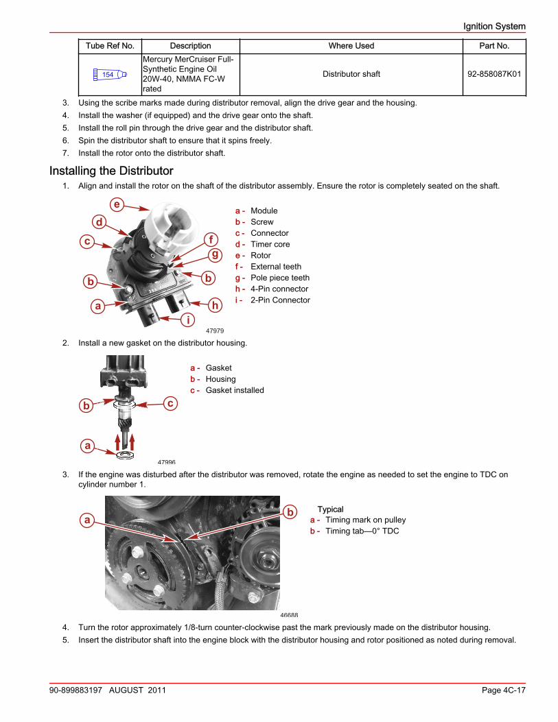
Installing the Distributor1. Align and install the rotor on the shaft of the distributor assembly. Ensure the rotor is completely seated on the shaft.
a - Moduleb - Screwc - Connectord - Timer coree - Rotorf - External teethg - Pole piece teethh - 4‑Pin connectori - 2‑Pin Connector
2. Install a new gasket on the distributor housing.
a - Gasketb - Housingc - Gasket installed
3. If the engine was disturbed after the distributor was removed, rotate the engine as needed to set the engine to TDC oncylinder number 1.
Typicala - Timing mark on pulleyb - Timing tab—0° TDC
4. Turn the rotor approximately 1/8‑turn counter‑clockwise past the mark previously made on the distributor housing.5. Insert the distributor shaft into the engine block with the distributor housing and rotor positioned as noted during removal.
a
b b
c fg
e
47979
hi
d
b c
a47996
a b
46688

Ignition System
Page 4C-18 90-899883197 AUGUST 2011
IMPORTANT: It may be necessary to move the rotor slightly to start gear mesh with camshaft gear, but the rotor shouldline up with the reference mark (made during removal) when the distributor is seated in place. The distributor shaft mustenter the oil pump shaft for complete installation.
3.0 MPI shown—3.0 TKS similara - Distributorb - Slotted‑shaftc - Position in block
6. Replace and tighten the distributor hold‑down screw and clamp.
a - Hold‑down clampb - Screw
Description Nm lb‑in. lb‑ftDistributor hold‑down screw 27 – 20
7. install the distributor cap and securely tighten the two screws retaining the cap.
47978
Distributor cap screws
8. Connect the primary lead to the coil.9. Install the spark plug wires and coil wire, if removed.
IMPORTANT: Wires must be installed in supports, if equipped, to prevent cross‑firing. Firing order is 1‑3‑4‑2.10. On 3.0 TKS models: set the ignition timing as outlined under Ignition Timing—3.0 TKS, in this section.11. On 3.0 MPI models: the ignition timing is not adjustable. Use a timing light to verify that the ignition timing falls within the
timing ranges.
47977
a
b
c
a
bb
a47976

Ignition System
90-899883197 AUGUST 2011 Page 4C-19
Distributor Component Testing—3.0 TKSGeneral Information
The following tests can be made with the distributor and coil mounted on or off the engine. The test procedures will check eachcomponent of the distributor and ignition coil. Distributor cap and rotor should be checked for corrosion, cracks, carbon tracks,or wear. Replace if needed.
Testing the Ignition ModuleIn order to test the module, an approved module tester, such as a Kent‑Moore Tester (J24642 or equivalent), must be used. Becertain to follow the manufacturer’s directions precisely for proper results. However, remember that corrosion on the terminalsof the module could cause improper ignition action and should therefore be inspected and cleaned as needed.
Testing the Pickup Coil1. Remove the distributor cap.2. Identify the two pickup coil leads. On almost all applications, one of these leads is white and the other is green. Remove
the connector that houses these two leads from the module.3. Set ohmmeter to "Rx1" scale. Connect one lead of ohmmeter to WHITE lead and the other to distributor housing. Reading
should be infinity. If not, replace the pickup coil.4. Repeat Step 3 with ohmmeter connected to green lead. Reading should be infinity. If not, replace the pickup coil.5. Set ohmmeter to "Rx100" scale. Connect ohmmeter to green and white pickup coil leads. Reading should be constant,
unchanging value in the range of 500‑1500 ohms. If not, replace the pickup coil. Be certain to flex leads by hand during thistest to locate possible intermittent "open" circuits (loss of continuity). If any exist, replace the pickup coil.
Ignition Timing—3.0 TKSIMPORTANT: Failure to follow the timing procedure instructions will result in improper timing, causing performance problemsand possible severe engine damage.1. Connect the timing light to the cylinder number 1 spark plug wire. Refer to Specifications for cylinder numbering and
location.
Timing Light 91‑ 99379
2. Connect the timing light power supply leads to a 12‑volt battery.3. Connect a shop tachometer to the engine.
Service Tachometer/Dwell Meter 91‑ 59339
NOTE: Before starting engine ensure that the timing tab and mark on damper are clean. Chalk or white paint on timingmark on damper may help visibility.
4. Supply cooling water to the engine and start the engine.5. Operate the engine at idle speed until it reaches normal operating temperature.6. Install a jumper wire between the two white‑wire leads on the distributor. Use Quicksilver 91‑818812A1, or fabricate a
jumper‑wire using a 15 cm (6 in.) length of 16‑gauge wire with two male bullet terminal ends connected.
a - White‑wire leadsb - Jumper‑wire leads
42953

Ignition System
Page 4C-20 90-899883197 AUGUST 2011
7. Bypass the shift interrupt switch, as follows:a. Disconnect the shift interrupt switch wires from the engine harness wires.
Typicala - Shift plateb - Shift interrupt switchc - Switch wires
b. Temporarily plug the male and female bullet connectors together on the engine harness wires.
a - Engine harness wiresb - Shift interrupt switch wires
IMPORTANT: Do not fail to reconnect these two wires to the shift interrupt switch when timing procedures arecomplete.
8. Aim the timing light at timing tab, located on the timing gear cover and crankshaft torsional damper. Check the timing.Refer to Specifications.
3.0 MPI shown—3.0 TKS similara - Timing markb - Timing tab
9. Adjust timing by loosening distributor clamp and rotating distributor body as required until timing mark on damper or pulleylines up with the mark on tab specified in Specifications. Tighten clamp and recheck location of timing mark.
10. Aim the timing light at the timing tab and recheck the location of timing mark. Repeat Step 8 until timing is correct.11. Stop the engine.12. Tighten the distributor hold‑down screw to specifications.
Description Nm lb‑in. lb‑ftDistributor hold‑down screw 27 – 20
13. Reconnect the two wires from the shift interrupt switch to the engine harness wires.IMPORTANT: Be sure to remove the jumper wire before returning the engine to service, otherwise timing will not advance.
14. Remove the jumper wire connected between the distributor white leads.15. With timing light still connected, start the engine. Operate at idle and at RPM indicated. Verify initial timing and total
advance as listed for your model:
a b
c
48000
47999
bbaa
a b
46688

Ignition System
90-899883197 AUGUST 2011 Page 4C-21
• If initial timing is 1° BTDC: 12° BTDC, plus or minus 2°. At 2400‑2800 RPM maximum (total) advance is obtained andshould be 23° BTDC (plus or minus 2°).
• If initial timing is 1° ATDC: 14° BTDC, plus or minus 2°. At 2400‑2800 RPM maximum (total) advance is obtained andshould be 25° BTDC (plus or minus 2°).
• If initial timing is 2° ATDC: 15° BTDC, plus or minus 2°. At 2400‑2800 RPM maximum (total) advance is obtained andshould be 26° BTDC (plus or minus 2°).
16. Stop the engine and remove the timing light.

Ignition System
Notes:
Page 4C-22 90-899883197 AUGUST 2011