shear strength of glued laminated timber made from
TRANSCRIPT
HAL Id: hal-00561301https://hal.archives-ouvertes.fr/hal-00561301
Submitted on 1 Feb 2011
HAL is a multi-disciplinary open accessarchive for the deposit and dissemination of sci-entific research documents, whether they are pub-lished or not. The documents may come fromteaching and research institutions in France orabroad, or from public or private research centers.
L’archive ouverte pluridisciplinaire HAL, estdestinée au dépôt et à la diffusion de documentsscientifiques de niveau recherche, publiés ou non,émanant des établissements d’enseignement et derecherche français ou étrangers, des laboratoirespublics ou privés.
Shear strength of glued laminated timber made fromEuropean beech timberSimon Aicher, Denny Ohnesorge
To cite this version:Simon Aicher, Denny Ohnesorge. Shear strength of glued laminated timber made from European beechtimber. European Journal of Wood and Wood Products, Springer Verlag, 2010, 69 (1), pp.143-154.�10.1007/s00107-009-0399-9�. �hal-00561301�
1
Simon Aicher1, Denny Ohnesorge² 1
Shear strength of glued laminated timber 2
made from European beech timber 3
1University of Stuttgart, MPA Stuttgart, Otto-Graf-Institute, Department Timber 4 Structures, Pfaffenwaldring 4, D-70569 Stuttgart (Vaihingen), Germany 5 E-mail: [email protected] 6 ²Albert-Ludwigs-University of Freiburg, Institute of Forest Utilization and Work 7 Science, Werthmannstr. 6, D-79085 Freiburg, Germany 8 E-Mail: [email protected] 9 10 Abstract This paper describes an investigation into the shear strength of glued laminated timber 11 (GLT) made from European beech. Special consideration was paid to the possible strength influ-12 ence of a frequently occurring discolouration of the timber, termed red heartwood, which is inher-13 ent to the species. The beech lamellae were visually graded according to German hardwood grad-14 ing standard DIN 4074-5. Grade LS13, conforming to European hardwood strength class D40, was 15 split into two sub-grades LS13- and LS13+. Additionally, modulus of elasticity (MOE) was de-16 termined by ultrasound pulse, longitudinal vibration and static tension tests. Sub-grade LS13+ 17 showed a mean density and MOE of 690 kg/m3 and 14,800 N/mm2, respectively. 18
The GLT shear strength was evaluated by means of four-point bending tests on structural sized I-19 shaped beams with a depth of 0.6 m and a span to depth ratio of 5:1. The slightly inhomogeneous 20 build-up of the cross-section conformed to glulam strength class GL42c. Two beam samples were 21 investigated, each with seven specimens, where one grouping had no red heartwood and the other 22 with an high red heartwood in the web laminations. Additionally block shear tests on bond line 23 strength were performed with standardized small specimens according to EN 392. 24
Neither the beam shear capacity tests nor the bond line block shear tests revealed an influence of 25 the red heartwood discolouration on strength. The fifth-percentile value of shear strength of all 26 beams was 3.5 N/mm2. The results of the block shear tests indicate that the present requirements 27 on minimum block shear strength are set too low in the European standard EN 386 with regard to 28 beech GLT. 29
Schubfestigkeit von Brettschichtholz aus 30
europäischem Buchenholz 31
Zusammenfassung Der Aufsatz berichtet über Untersuchungen zur Schubfestigkeit von 32 Brettschichtholz (BSH) aus Europäischer Buche. Besondere Beachtung wurde dem eventuellen 33 Festigkeitseinfluss einer häufig auftretenden holzartspezifischen Verfärbung des Holzes, Rotkern 34 genannt, zugemessen. Die Buchenholz-Brettlamellen wurden visuell nach der deutschen 35 Laubholzsortiernorm DIN 4074-5 sortiert. Die Sortierklasse LS13, die der Europäischen 36
2
Laubholzfestigkeitsklasse D40 zugeordnet ist, wurde in die Klassen LS13- und LS13+ 1 untergliedert. Zusätzlich wurde der Elastizitätsmodul mittels Ultraschalllaufzeit, Längsschwingung 2 und statischer Zugversuche bestimmt. Die Sortierunterklasse LS13+ wies eine mittlere Rohdichte 3 von 690 kg/m3 und einen Elastizitätsmodul von 14.800 N/mm2 auf. 4
Die BSH-Schubfestigkeitsuntersuchungen wurden mittels Vier-Punkt-Biegeversuchen an 5 großformatigen I-Trägern mit einer Querschnittshöhe von 0,6 m und einem Stützweiten-6 Querschnittshöhenverhältnis von 5:1 durchgeführt. Der geringfügig inhomogene 7 Querschnittsaufbau entsprach der BSH-Festigkeitsklasse GL42c. Die Untersuchungen umfassten 8 zwei Trägerkollektive, mit je sieben Prüfkörpern, jeweils ohne bzw. mit hohem Rotkernanteil in 9 den Steglamellen. Weiterhin wurden Blockscherversuche zur Klebfugenfestigkeit an kleinen 10 Normprüfkörpern nach EN 392 durchgeführt. 11
Weder die Schubtragfähigkeitsversuche an den Biegeträgern noch die Klebefugen-12 Blockscherversuche zeigten einen Festigkeitseinfluss der Rotkernverfärbung. Die 5%-Quantile der 13 Schubfestigkeiten aller Träger ergab sich zu 3,5 N/mm2. Die Ergebnisse der Blockscherversuche 14 weisen darauf hin, dass die derzeitigen Anforderungen an die Klebfugenscherfestigkeit in EN 386 15 in Bezug auf Buchen-BSH zu niedrig sind. 16
1. Introduction 17
The higher strength and stiffness properties of beech wood as compared to most 18
softwood species are well known. The relative ease of glueability of beech wood 19
is highlighted in the proliferation of beech wood objects manufactured in the solid 20
wood furniture industry where beech represents the predominantly used material 21
in Europe. The possibility of using beech timber for structural glulam beams was 22
first successfully demonstrated in the mid-sixties by Egner and Kolb (1966) and 23
Kolb (1968). Later Gehri (1980; 1985) once again pointed out the high strength 24
and stiffness potential of beech glulam. However, up to today, glulam made of 25
beech timber has been used only on rare occasions. This situation should change 26
considerably in the coming decades due to several reasons, inter alia altered silvi-27
cultural policies and the need for timber products with enhanced performance 28
characteristics. Within the last ten years a considerable number of investigations 29
focused on several aspects of structural use of beech timber such as grading, fin-30
ger joint strength, glue line integrity, beam strengths, influences of red heartwood 31
(Glos and Lederer 2000; Aicher et al. 2001; Frühwald et al. 2003; Bernasconi 32
2004; Pöhler et al. 2006; Blaß et al. 2005; Frese and Blaß 2005; Frese 2006; 33
Aicher and Reinhardt 2007; Ohnesorge et. al. 2006; 2008). The most comprehen-34
sive investigations on grading of beech timber, strength of beech lamellae as well 35
3
as bending strength and stiffness of beech glulam beams were performed by Glos 1
and Lederer (2000), Blaß et al. (2005) and Frese (2006). The latter investigations 2
laid the foundations for introducing beech glulam as a designable and reliable 3
building product in the construction market by means of a recently drafted general 4
building approval Z-9.1-679 (DIBt, 2009). For the time being, the use of beech 5
glulam is restricted to service class 1 as defined in EN 1995-1-1 due to low natu-6
ral durability and relative high shrinkage/swelling coefficients of the timber. 7
Despite these promising steps, some basic questions related to beech glulam re-8
main to be resolved. One major issue is (bond) shear strength, which becomes the 9
most important structural material property, next to bending strength, in the de-10
sign of glulam beams in certain cases of load configurations and span to depth 11
ratios. At present, the specification of characteristic shear strength of beech glu-12
lam is not based on consistent investigations on this material property relevant for 13
structural sized beams. Investigations on this issue are presented in this paper. 14
2. Material and test specimens 15
The material for this investigation was purchased in 2005 from a hardwood saw-16
mill in the state of Baden-Württemberg, Germany. A total of 28 logs, already 17
sawn into boards of 45 mm thickness, were specifically selected with regard to the 18
amount of red heartwood that each contained. The boards had been air-seasoned 19
for up to five years under protected external conditions. The red heartwood 20
amount of the logs varied from 0 to 60 % of the diameter at the bottom log and the 21
quality grades were B or B/C – according to the former German round wood grad-22
ing act “HKS” (1969). 23
2.1. Beech lamellae grading and material characteristics 24
Prior to sawing the lamellae to a width of 130 mm, the boards were kiln-dried to 25
an equilibrium moisture content of about 11 %. As part of the lamellae sawing 26
process, larger defects such as knots with diameters of more than 8 cm, pith, and 27
transverse cracks were eliminated by crosscutting. 28
2.1.1. Visual Grades, density and red heartwood 29
4
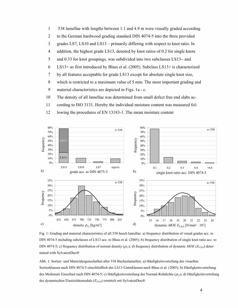
538 lamellae with lengths between 1.1 and 4.9 m were visually graded according 1
to the German hardwood grading standard DIN 4074-5 into the three provided 2
grades LS7, LS10 and LS13 – primarily differing with respect to knot ratio. In 3
addition, the highest grade LS13, denoted by knot ratios of 0.2 for single knots 4
and 0.33 for knot groupings, was subdivided into two subclasses LS13− and 5
LS13+ as first introduced by Blass et al. (2005). Subclass LS13+ is characterized 6
by all features acceptable for grade LS13 except for absolute single knot size, 7
which is restricted to a maximum value of 5 mm. The most important grading and 8
material characteristics are depicted in Figs. 1a - c. 9
The density of all lamellae was determined from small defect free end slabs ac-10
cording to ISO 3131. Hereby the individual moisture content was measured fol-11
lowing the procedures of EN 13183-1. The mean moisture content 12
LS13-
n=538
LS13+
0%10%20%30%40%50%60%70%80%
LS13 LS10 LS7 rejectsgrade class acc. to DIN 4074-5
frequ
ency
a)
freq
uenc
y
grade acc. to DIN 4075-5
LS13+
LS13-
n=538
0%10%20%30%40%50%60%70%80%
0.1 0.2 0.3 0.4 >0.4single knot area ratio acc. DIN 4074-5
frequ
ency
b)
freq
uenc
y
single knot ratio acc. DIN 4074-5
n=538
0%
5%10%
15%20%
25%30%
35%
625 650 675 700 725 750 775 800 825
density- r12 [kg/m³]
frequ
ency
c)
freq
uenc
y
density ρ12 [kg/m³]
n=538
0%
5%
10%
15%20%
25%
30%
35%
15 16 17 18 19 20 21 22 23 24dynamic MOE EUS,0 [GPa=N/mm²*10-3]
frequ
ency
d)
freq
uenc
y
dynamic MOE EUS,0 [N/mm² ⋅ 103]
Fig. 1: Grading and material characteristics of all 538 beech lamellae: a) frequency distribution of visual grades acc. to
DIN 4074-5 including subclasses of LS13 acc. to Blass et al. (2005); b) frequency distribution of single knot ratio acc. to
DIN 4074-5; c) frequency distribution of normal density (ρ12); d) frequency distribution of dynamic MOE (EUS,0) deter-
mined with SylvatestDuo®
Abb. 1: Sortier- und Materialeigenschaften aller 538 Buchenlamellen: a) Häufigkeitsverteilung der visuellen
Sortierklassen nach DIN 4074-5 einschließlich der LS13-Unterklassen nach Blass et al. (2005); b) Häufigkeitsverteilung
des Merkmals Einzellast nach DIN 4074-5; c) Häufigkeitsverteilung der Normal-Rohdichte (ρ12); d) Häufigkeitsverteilung
des dynamischen Elastizitätsmoduls (EUS,0) ermittelt mit SylvatestDuo®
5
(± SD = standard deviation) of all lamellae was 11.3 ± 1.0 %. The obtained fre-1
quency distribution of normal density ρ12 is depicted in Fig. 1c. The mean density 2
(± SD) was 690 ± 55 kg/m3; no lamellae showed a density less than 600 kg/m3. 3
The red heartwood amount was measured on all lamellae at the edges and wide 4
faces following the provisions of chap. 5.8 of DIN 4074-5. In total, 51 % of all 5
lamellae contained less than 5 % red heartwood. The amount of red heartwood in 6
the discoloured lamellae (those with more than 5 % red heartwood) varied roughly 7
from 5 % to 70 % and was on average 25 %, very similar for the edges and faces. 8
2.1.2. Modulus of elasticity, tension strength 9
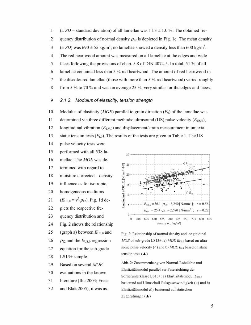
Modulus of elasticity (MOE) parallel to grain direction (E0) of the lamellae was 10
determined via three different methods: ultrasound (US) pulse velocity (EUS,0), 11
longitudinal vibration (ELV,0) and displacement/strain measurement in uniaxial 12
static tension tests (Et,0). The results of the tests are given in Table 1. The US 13
pulse velocity tests were 14
performed with all 538 la-15
mellae. The MOE was de-16
termined with regard to – 17
moisture corrected – density 18
influence as for isotropic, 19
homogeneous mediums 20
(EUS,0 = v2⋅ρ12). Fig. 1d de-21
picts the respective fre-22
quency distribution and 23
Fig. 2 shows the relationship 24
(graph a) between EUS,0 and 25
ρ12 and the EUS,0 regression 26
equation for the sub-grade 27
LS13+ sample. 28
Based on several MOE 29
evaluations in the known 30
literature (Ilic 2003; Frese 31
and Blaß 2005), it was as-32
600 625 650 675 700 725 750 775 800 825density r12 [kg/m³]
0.22 ;][N/mm 680,2 25.4 2t,0 = − ⋅= 12 rE ρ
0
5
10
15
20
25
30
575
b) Et,0
a) EUS,0
long
itudi
nal M
OE;
E0
[N/m
m²·
10³]
0density ρ12 [kg/m³]
600 625 650 675 700 725 750 775 800 8250
5
10
15
20
25
30
56.0 ;N/mm[ 240,6 36.1 2US,0 = ]− ⋅= 12 rE ρ
Fig. 2: Relationship of normal density and longitudinal
MOE of sub-grade LS13+: a) MOE EUS,0 based on ultra-
sonic pulse velocity (○) and b) MOE Et,0 based on static
tension tests (▲)
Abb. 2: Zusammenhang von Normal-Rohdichte und
Elastizitätsmodul parallel zur Faserrichtung der
Sortierunterklasse LS13+: a) Elastizitätsmodul EUS,0
basierend auf Ultraschall-Pulsgeschwindigkeit (○) und b)
Elastizitätsmodul Et,0 basierend auf statischen
Zugprüfungen (▲)
6
sumed and finally shown that the presented EUS,0 values are considerably higher in 1
comparison to other non-destructive testing (NDT) and direct measurement meth-2
ods. In order to verify/correct the EUS,0 values, static uniaxial, longitudinal tension 3
tests with displacement/strain measurements were carried out with 51 lamellae of 4
sub-grade LS13+. The specimens had a test length l of 400 mm (= 3.3 ⋅ blam, 5
where blam = lamellae width) clear of the machine grips. The displacement/strain 6
measurement was performed in the centre of l over a distance of 200 mm follow-7
ing the principles of EN 408. All tests were done in stroke control with a constant 8
displacement rate of the actuator of 0.04 mm/sec. 9
The Et,0 results given in Table 1 and Fig. 2 conform closely to data from the rele-10
vant literature (Frese and Blaß 2005). The mean (± SD) and the fifth percentile of 11
the tension strength ft,0 and the relationship between tension strength and modulus 12
of elasticity Et,0 (in N/mm2) obtained for the LS13+ laminations were: 13
N/mm²2.94 ; N/mm²1.274.29 t,05t,0 = ± = ff and 14 0.64 ; N/mm²67.090.0107 t,0t,0 = −⋅= rEf 15
On average the ratio of MOEs determined by US pulse velocity measurement and 16
direct tension tests for sub-grade LS13+ was EUS,0/Et,0 = 1.27. At present, no fully 17
convincing answers can be given with regard to the reason of the rather large dis-18
crepancy of the specific NDT and the direct MOE measurement. In addition to 19
ultra-sound pulse velocity and static tension tests, MOE was determined on 32 20
randomly selected lamellae (t = 32 and 38 mm) of sub-grade LS13+ using com-21
mercially available longitudinal vibration test equipment. The results given in 22
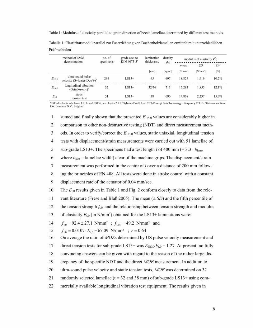
Table 1: Modulus of elasticity parallel to grain direction of beech lamellae determined by different test methods
Tabelle 1: Elastizitätsmodul parallel zur Faserrichtung von Buchenholzlamellen ermittelt mit unterschiedlichen
Prüfmethoden
method of MOE determination
no. of specimens
grade acc. to DIN 4075-5a
lamination thickness t
density ρ12
modulus of elasticity E0 mean SD CV
[mm] [kg/m³] [N/mm²] [N/mm²] [%]
EUS,0 ultra-sound pulse velocity (SylvatestDuo®)b 294 LS13+ 45 697 18,827 1,919 10.2%
ELV,0 longitudinal vibration
(Grindosonic)c 32 LS13+ 32/36 713 15,283 1,855 12.1%
Et,0 static tension test 51 LS13+ 38 690 14,868 2,237 15.0%
aLS13 divided in subclasses LS13− and LS13+; see chapter 2.1.1; bSylvatestDuo® from CBT-Concept Bois Technology – frequency 22 kHz; cGrindosonic from J.W. Lemmens N.V., Belgium
7
Table 1, were slightly (3 %) higher than the MOEs obtained in the static tension 1
tests. 2
2.2. I-shaped beam specimens 3
2.2.1. General comments 4
Shear strength of glulam in structural sizes cannot be derived directly from small 5
(clear) block shear specimens as defined in EN 392 or ASTM D143 neither from 6
medium sized specimens according to EN 408. Small and medium sized speci-7
mens may be used, provided apt calibration/adjustment procedures for extrapola-8
tion to large scale components exist. Such provisions for instance are given in 9
ASTM D3737, addressing ASTM D2915 and ASTM D2555, to derive allowable 10
glulam shear stresses. Nevertheless, it has been demonstrated (Yeh and William-11
son 2001) that the specific approach leads to estimates that are too conservative 12
when compared to results derived from full-scale tests (see also ASTM D3737). 13
In the last three decades different cross-sectional shapes, build-ups and loading 14
configurations have been investigated for determination of shear strength from 15
structural sized glulam specimens (Keenan et al. 1985; Soltis and Rammer 1994; 16
Schickhofer and Obermayr 1998; Yeh and Williamson 2001; Schickhofer 2001). 17
So far, primarily rectangular cross-sections were used. Their use was undertaken 18
partly in conjunction with special provisions that increased the strength in the 19
bending tension zone in order to avoid bending failure. Finger jointed laminations 20
were used by Soltis and Rammer (1994) whereas the specimens by Yeh and Wil-21
liamson (2001) had no end joints in the tension zone. Keenan et al. (1985) used 22
outer lamellae made of hardwood. I-shaped glulam cross-sections, partly in com-23
bination with special outer lamellae (i.e., LVL), were used by Schickhofer and 24
Obermayr (1998) and Schickhofer (2001), hereby following the ideas of Korin’s 25
tests (1996) with solid wood. A review of specimen build-ups in the known litera-26
ture showed that the highest shear failure ratio up to about 100 % is obtained by 27
means of an I-shaped cross-section with high strength lamellae without end joints 28
in the bending tension zone. Further, in the given case, no special provisions for 29
preventing crushing on the outer lamination in the bearing areas should be neces-30
sary, due to the relatively high compression strength perpendicular to grain of 31
beech wood in comparison to softwoods. 32
8
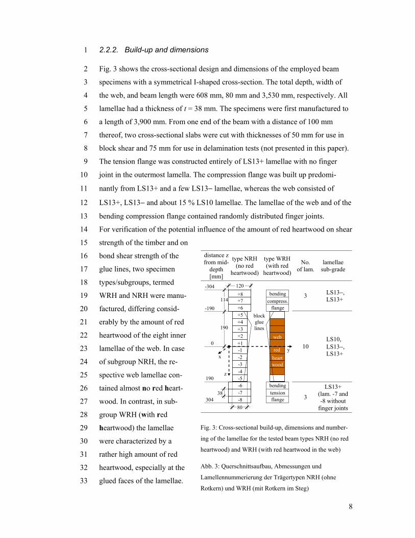
2.2.2. Build-up and dimensions 1
Fig. 3 shows the cross-sectional design and dimensions of the employed beam 2
specimens with a symmetrical I-shaped cross-section. The total depth, width of 3
the web, and beam length were 608 mm, 80 mm and 3,530 mm, respectively. All 4
lamellae had a thickness of t = 38 mm. The specimens were first manufactured to 5
a length of 3,900 mm. From one end of the beam with a distance of 100 mm 6
thereof, two cross-sectional slabs were cut with thicknesses of 50 mm for use in 7
block shear and 75 mm for use in delamination tests (not presented in this paper). 8
The tension flange was constructed entirely of LS13+ lamellae with no finger 9
joint in the outermost lamella. The compression flange was built up predomi-10
nantly from LS13+ and a few LS13− lamellae, whereas the web consisted of 11
LS13+, LS13− and about 15 % LS10 lamellae. The lamellae of the web and of the 12
bending compression flange contained randomly distributed finger joints. 13
For verification of the potential influence of the amount of red heartwood on shear 14
strength of the timber and on 15
bond shear strength of the 16
glue lines, two specimen 17
types/subgroups, termed 18
WRH and NRH were manu-19
factured, differing consid-20
erably by the amount of red 21
heartwood of the eight inner 22
lamellae of the web. In case 23
of subgroup NRH, the re-24
spective web lamellae con-25
tained almost no red heart-26
wood. In contrast, in sub-27
group WRH (with red 28
heartwood) the lamellae 29
were characterized by a 30
rather high amount of red 31
heartwood, especially at the 32
glued faces of the lamellae. 33
distance z from mid-
depth [mm]
type NRH(no red
heartwood)
type WRH (with red
heartwood)
No. of lam.
lamellae sub-grade
3 LS13−, LS13+
10 LS10, LS13−,LS13+
blockgluelines
flange
bending
web
-8-7-6-5-4-3-2-1
+8+7+6+5+4+3+2+10
190
304
-304
compress.
flange
bendingtension
y
z
x
114
-190
190
38
120
80
red heart wood
3
LS13+ (lam. -7 and -8 without
finger joints
Fig. 3: Cross-sectional build-up, dimensions and number-
ing of the lamellae for the tested beam types NRH (no red
heartwood) and WRH (with red heartwood in the web)
Abb. 3: Querschnittsaufbau, Abmessungen und
Lamellennummerierung der Trägertypen NRH (ohne
Rotkern) und WRH (mit Rotkern im Steg)
9
The percentage of red heartwood in the glued interface ranged from about 60 to 1
95 %. In total, seven specimens of each type (WRH and NRH) were produced. 2
2.2.3. Manufacture 3
The production of the specimens was carried out in a glulam company with ex-4
perience in the production of GLT made of hardwoods. A total of 340 lamellae 5
with a cross-section of 45 mm x 130 mm, and an average length of 2.6 m, grouped 6
in (sub)grades of LS10 (14 %), LS13− (26 %) and LS13+ (60 %) were finger-7
jointed to lamellae of 20 m length. The average moisture content at the time of 8
finger jointing and face gluing was 11.1 %. Length and pitch of the employed 9
finger joint profile conformed to 15 mm and 3.8 mm. For gluing the finger joints 10
and equally for gluing the faces of the lamellae a widely used two-component 11
melamine urea adhesive (Kauramin 683 with hardener 688) tested and approved 12
according to the requirements of EN 301 for the purpose of softwood and beech 13
wood gluing was used in intermixed condition with an adhesive to hardener 14
weight ratio of 100:50. After 30 days of curing the finger joints, and immediately 15
before face gluing, all lamellae were planed to a thickness of 38 mm. 16
The gluing of the I-shaped cross-section was then performed in a two-step proc-17
ess. First, the flanges, and the web, all with same lamination width (130 mm) were 18
glued separately. After one week of curing, the webs were sawn on one side to a 19
width of 90 mm and were then planed on both sides to a final width of 80 mm. 20
Then the "block-gluing" method was used, when adhering the web to the flanges. 21
In all cases, the adhesive spray was applied on both sides, amounting to about 22
250 g/m2 per side. The open assembly time was ≤ 5 minutes and the closed as-23
sembly time ranged from 30 to 50 minutes. The pressure applied during the face 24
gluing process was 1.1 N/mm2, and was held for 18 hours at about 30°C and 25
60 ± 10% relative humidity. The total curing time of the specimens in sheltered 26
conditions of 20°C ±5°C before testing was 60 days. 27
3. Test methods and stress distribution analysis 28
3.1. Beam specimens 29
3.1.1. Test set-up and procedure 30
10
The most commonly used loading methods, in general with a span to depth ratio 1
of about 5:1 to 6:1, are either one-span tests – some with three-point loading 2
(Schickhofer 2001), some with four-point loading (Yeh and Williamson 2001; 3
ASTM D3737, Annex A 7) – or two-span tests with five-point loading (Soltis and 4
Rammer 1994; Schickhofer 2001). The latter test configuration, first used for ad-5
vanced composite materials (Jegley and Williams 1988) led to a high shear failure 6
rate of about 70 to 90 % in the glulam tests conducted by Soltis and Rammer, 7
which made use of rectangular cross-sections. On the other hand, in shear strength 8
tests with solid wood (Lam et al. 1995) a very low shear failure rate of solely 9
40 % was obtained. Drawbacks to the two-span method are difficulties in detec-10
tion of crack formation and indications that the obtained shear strengths are higher 11
as compared to one-span test configurations. The latter is most likely due to super-12
imposed compression stresses perpendicular to grain. Based on the evaluation of 13
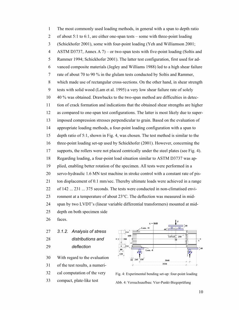
appropriate loading methods, a four-point loading configuration with a span to 14
depth ratio of 5:1, shown in Fig. 4, was chosen. The test method is similar to the 15
three-point loading set-up used by Schickhofer (2001). However, concerning the 16
supports, the rollers were not placed centrically under the steel plates (see Fig. 4). 17
Regarding loading, a four-point load situation similar to ASTM D3737 was ap-18
plied, enabling better rotation of the specimen. All tests were performed in a 19
servo-hydraulic 1.6 MN test machine in stroke control with a constant rate of pis-20
ton displacement of 0.1 mm/sec. Thereby ultimate loads were achieved in a range 21
of 142 ... 231 ... 375 seconds. The tests were conducted in non-climatised envi-22
ronment at a temperature of about 23°C. The deflection was measured in mid-23
span by two LVDT’s (linear variable differential transformers) mounted at mid-24
depth on both specimen side 25
faces. 26
3.1.2. Analysis of stress 27
distributions and 28
deflection 29
With regard to the evaluation 30
of the test results, a numeri-31
cal computation of the very 32
compact, plate-like test 33
35303040245
125
80
120
114608
zx
125
F
10
150
380
114
40
40
55
Lam. +8
Lam. -8
zy
x = 840
250
40
Fig. 4: Experimental bending set-up: four-point loading
Abb. 4: Versuchsaufbau: Vier-Punkt-Biegeprüfung
11
specimen was performed, due to the fact that its proportions limit the use of beam 1
theory. 2
In the numerical analysis the specimen and test configuration were approximated 3
using a 2D finite element (FE) model, assuming plane stress conditions. The inter-4
faces between the very stiff loading and support plates were modelled by contact 5
elements. The results given in Figs. 5a – c are based on MOE values 6
E0 = Ex = 14.500 N/mm² for the flanges and 13.500 N/mm² for the web, reflecting 7
the actual build-up of the test specimens. The other stiffness parameters/ratios 8
were chosen as: E0/E90 = 20, E0/G = 16, νyx = (Ex/Ey) · νxy = 0.4. The effects of 9
the above stiffness assumptions were checked with parameter studies, which can 10
be summarized as following: small changes of the ratio E0/E90 in the range of 11
about 18…22 and a νyx range of 0.35 – 0.45 have almost no influence on stresses 12
and deflection. Changes of the E0/G ratio in the perceivable range of 14 to 18 af-13
fect primarily deflection, as the global stiffness of the compact specimen depends 14
significantly on shear modulus. 15
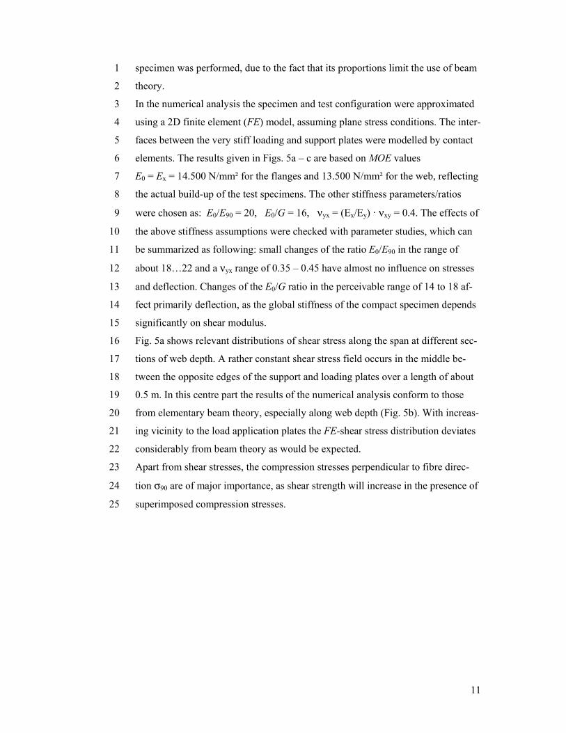
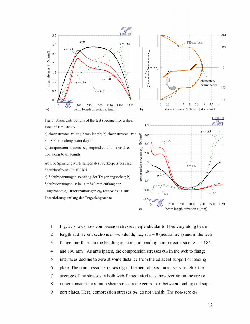
Fig. 5a shows relevant distributions of shear stress along the span at different sec-16
tions of web depth. A rather constant shear stress field occurs in the middle be-17
tween the opposite edges of the support and loading plates over a length of about 18
0.5 m. In this centre part the results of the numerical analysis conform to those 19
from elementary beam theory, especially along web depth (Fig. 5b). With increas-20
ing vicinity to the load application plates the FE-shear stress distribution deviates 21
considerably from beam theory as would be expected. 22
Apart from shear stresses, the compression stresses perpendicular to fibre direc-23
tion σ90 are of major importance, as shear strength will increase in the presence of 24
superimposed compression stresses. 25
12
Fig. 5c shows how compression stresses perpendicular to fibre vary along beam 1
length at different sections of web depth, i.e., at z = 0 (neutral axis) and in the web 2
flange interfaces on the bending tension and bending compression side (z = ± 185 3
and 190 mm). As anticipated, the compression stresses σ90 in the web to flange 4
interfaces decline to zero at some distance from the adjacent support or loading 5
plate. The compression stresses σ90 in the neutral axis mirror very roughly the 6
average of the stresses in both web-flange interfaces, however not in the area of 7
rather constant maximum shear stress in the centre part between loading and sup-8
port plates. Here, compression stresses σ90 do not vanish. The non-zero σ90 9
0.0
0.5
1.0
1.5
2.0
2.5
3.0
3.5
0 250 500 750 1000 1250 1500 1750beam length direction x [mm]
shea
r stre
ss [N
/mm
²]
z=0
z = 190z = -190
shea
r stre
sses
τ[N
/mm
²]
a)
z = -185
z = 185
x = 840
0 500 750 1000 1250 1500 1750beam length direction x [mm]
0 0,5 1 1,5 2 2,5 3 3,5 4
shear stressτ [N/mm²]
-304
304
0
-190
190
FE-analysis
elementary beam theory
b)
y
+ z
x
- z
shear stresses τ [N/mm²] at x = 8400.5 1.5 2.5 3.5
Fig. 5: Stress distributions of the test specimen for a shear
force of V = 100 kN
a) shear stresses τ along beam length; b) shear stresses τ at
x = 840 mm along beam depth;
c) compression stresses σ90 perpendicular to fibre direc-
tion along beam length
-0.5
0.0
0.5
1.0
1.5
2.0
2.5
3.0
3.5
0 250 500 750 1000 1250 1500 1750
beam length direction x [mm]
com
pres
sion
stres
s per
pent
icul
ar to
z = 0
z = -190
z = 185co
mpr
essi
on st
ress
es σ
90[N
/mm
²]
c)
z = -185
z = 190
x = 840
com
pres
sion
stre
sses
σ90
[N/m
m²]
beam length direction x [mm]0 500 750 1000 1250 1500 1750
Abb. 5: Spannungsverteilungen des Prüfkörpers bei einer
Schubkraft von V = 100 kN
a) Schubspannungen τ entlang der Trägerlängsachse; b)
Schubspannungen τ bei x = 840 mm entlang der
Trägerhöhe; c) Druckspannungen σ90 rechtwinklig zur
Faserrichtung entlang der Trägerlängsachse
13
stresses – distributed, parabolically over web depth – result form the inclined 1
compression force, which stretches diagonally from the support plate to the adja-2
cent loading plate in the very compact, plate-like specimen. On average σ90 nor-3
malized to unit shear force V = 1 kN is about 0.002 (N/mm2/kN). Hence, for mean 4
shear force capacity of all beams tests, being Vu = 209 kN (see below), the super-5
imposed compression stress normal to shear fracture plane at mid-depth is about 6
0.4 N/mm2. This level of compression stress is rather low and should have little 7
effect on a potential increase of shear strength. 8
The computational (mid-span) deflection, expressed as mid-span (spring) stiffness 9
S = F/w (ℓ/2) is 25.77 kN/mm. 10
3.2. Block shear tests 11
Block shear tests, used to determine bond line shear strength, were carried out 12
with specimens taken from full cross-sectional slabs with 50 mm thickness, cut 13
from each beam specimen prior to the shear capacity experiments. The tests were 14
performed according to EN 392 with sticks of 50 mm width cut at mid-width over 15
full depth from the I-shaped cross-sectional slabs. The sticks were conditioned for 16
eight weeks in a climate of 20°C and 65 % relative humidity. The testing was 17
conducted with a constant rate of crosshead displacement such that failures oc-18
curred within about 20 sec. 19
4. Results and discussion 20
4.1. Beam shear capacity tests 21
The load versus mid-span deflection curves were strictly linear for all specimens 22
up to about 60 % of the ultimate shear force capacity Vu = Fu/2. Fracture and ulti-23
mate load occurred in all cases in a brittle, instantaneous manner, whereby 13 of 24
the 14 beams failed in shear with a crack over the full width of the web. One beam 25
failed in bending due to a bending tension fracture in the outermost lamella. The 26
hereby obtained shear force level conformed to the average of the other beams 27
that failed in shear and hence was included in the evaluation. The lengths of the 28
shear cracks ranged roughly from half to full beam length. The position of the 29
shear crack plane within web depth varied considerably. 30
14
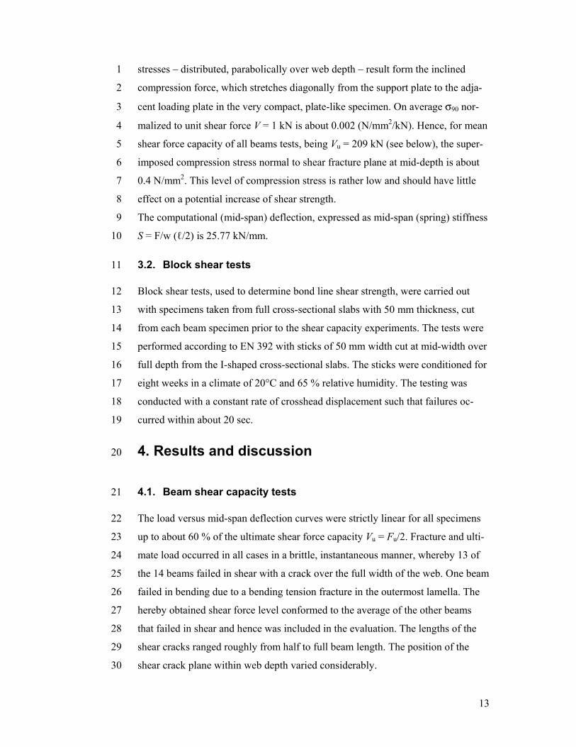
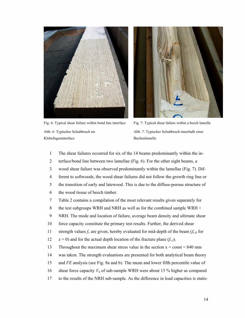
The shear failures occurred for six of the 14 beams predominantly within the in-1
terface/bond line between two lamellae (Fig. 6). For the other eight beams, a 2
wood shear failure was observed predominantly within the lamellae (Fig. 7). Dif-3
ferent to softwoods, the wood shear failures did not follow the growth ring line or 4
the transition of early and latewood. This is due to the diffuse-porous structure of 5
the wood tissue of beech timber. 6
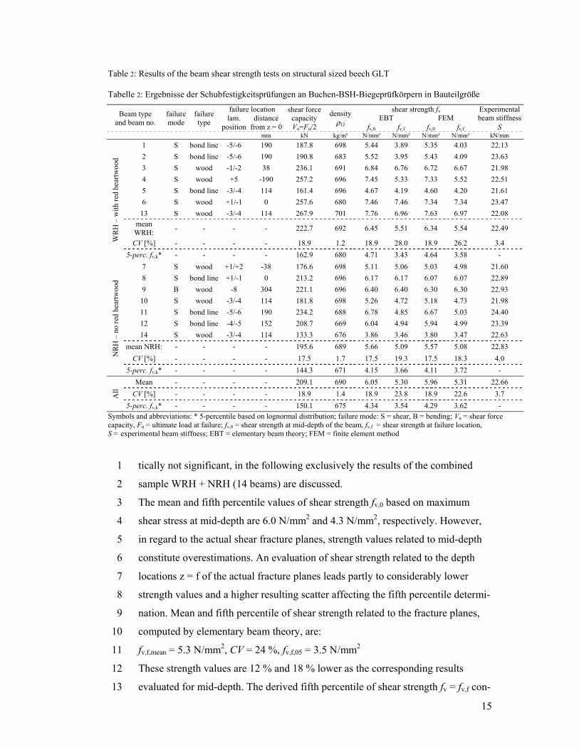
Table 2 contains a compilation of the most relevant results given separately for 7
the test subgroups WRH and NRH as well as for the combined sample WRH + 8
NRH. The mode and location of failure, average beam density and ultimate shear 9
force capacity constitute the primary test results. Further, the derived shear 10
strength values fv are given, hereby evaluated for mid-depth of the beam (fv,0 for 11
z = 0) and for the actual depth location of the fracture plane (fv,f). 12
Throughout the maximum shear stress value in the section x = const = 840 mm 13
was taken. The strength evaluations are presented for both analytical beam theory 14
and FE analysis (see Fig. 8a and b). The mean and lower fifth percentile value of 15
shear force capacity Vu of sub-sample WRH were about 13 % higher as compared 16
to the results of the NRH sub-sample. As the difference in load capacities is statis-17
Fig. 6: Typical shear failure within bond line interface Fig. 7: Typical shear failure within a beech lamella
Abb. 6: Typischer Schubbruch im
Klebefugeninterface
Abb. 7: Typischer Schubbruch innerhalb einer
Buchenlamelle
15
tically not significant, in the following exclusively the results of the combined 1
sample WRH + NRH (14 beams) are discussed. 2
The mean and fifth percentile values of shear strength fv,0 based on maximum 3
shear stress at mid-depth are 6.0 N/mm2 and 4.3 N/mm2, respectively. However, 4
in regard to the actual shear fracture planes, strength values related to mid-depth 5
constitute overestimations. An evaluation of shear strength related to the depth 6
locations z = f of the actual fracture planes leads partly to considerably lower 7
strength values and a higher resulting scatter affecting the fifth percentile determi-8
nation. Mean and fifth percentile of shear strength related to the fracture planes, 9
computed by elementary beam theory, are: 10
fv,f,mean = 5.3 N/mm2, CV = 24 %, fv,f,05 = 3.5 N/mm2 11
These strength values are 12 % and 18 % lower as the corresponding results 12
evaluated for mid-depth. The derived fifth percentile of shear strength fv = fv,f con-13
Table 2: Results of the beam shear strength tests on structural sized beech GLT
Tabelle 2: Ergebnisse der Schubfestigkeitsprüfungen an Buchen-BSH-Biegeprüfkörpern in Bauteilgröße
Beam type and beam no.
failure mode
failure type
failure location shear force capacityVu=Fu/2
density ρ12
shear strength fv Experimental beam stiffnesslam.
positiondistance
from z = 0EBT FEM
fv,0 fv,f fv,0 fv,f S
mm kN kg/m³ N/mm² N/mm² N/mm² N/mm² kN/mm
WR
H –
with
red
hear
twoo
d
1 S bond line -5/-6 190 187.8 698 5.44 3.89 5.35 4.03 22.13 2 S bond line -5/-6 190 190.8 683 5.52 3.95 5.43 4.09 23.63 3 S wood -1/-2 38 236.1 691 6.84 6.76 6.72 6.67 21.98 4 S wood +5 -190 257.2 696 7.45 5.33 7.33 5.52 22.51 5 S bond line -3/-4 114 161.4 696 4.67 4.19 4.60 4.20 21.61 6 S wood +1/-1 0 257.6 680 7.46 7.46 7.34 7.34 23.47
13 S wood -3/-4 114 267.9 701 7.76 6.96 7.63 6.97 22.08 mean WRH: - - - - 222.7 692 6.45 5.51 6.34 5.54 22.49
CV [%] - - - - 18.9 1.2 18.9 28.0 18.9 26.2 3.4 5-perc. fv,k* - - - - 162.9 680 4.71 3.43 4.64 3.58 -
NR
H –
no
red
hear
twoo
d
7 S wood +1/+2 -38 176.6 698 5.11 5.06 5.03 4.98 21.60 8 S bond line +1/-1 0 213.2 696 6.17 6.17 6.07 6.07 22.89 9 B wood -8 304 221.1 696 6.40 6.40 6.30 6.30 22.93
10 S wood -3/-4 114 181.8 698 5.26 4.72 5.18 4.73 21.98 11 S bond line -5/-6 190 234.2 688 6.78 4.85 6.67 5.03 24.40 12 S bond line -4/-5 152 208.7 669 6.04 4.94 5.94 4.99 23.39 14 S wood -3/-4 114 133.3 676 3.86 3.46 3.80 3.47 22.63
mean NRH: - - - - 195.6 689 5.66 5.09 5.57 5.08 22.83 CV [%] - - - - 17.5 1.7 17.5 19.3 17.5 18.3 4.0
5-perc. fv,k* - - - - 144.3 671 4.15 3.66 4.11 3.72 -
All
Mean - - - - 209.1 690 6.05 5.30 5.96 5.31 22.66 CV [%] - - - - 18.9 1.4 18.9 23.8 18.9 22.6 3.7
5-perc. fv,k* - - - - 150.1 675 4.34 3.54 4.29 3.62 - Symbols and abbreviations: * 5-percentile based on lognormal distribution; failure mode: S = shear, B = bending; Vu = shear force capacity, Fu = ultimate load at failure; fv,0 = shear strength at mid-depth of the beam, fv,f = shear strength at failure location, S = experimental beam stiffness; EBT = elementary beam theory; FEM = finite element method
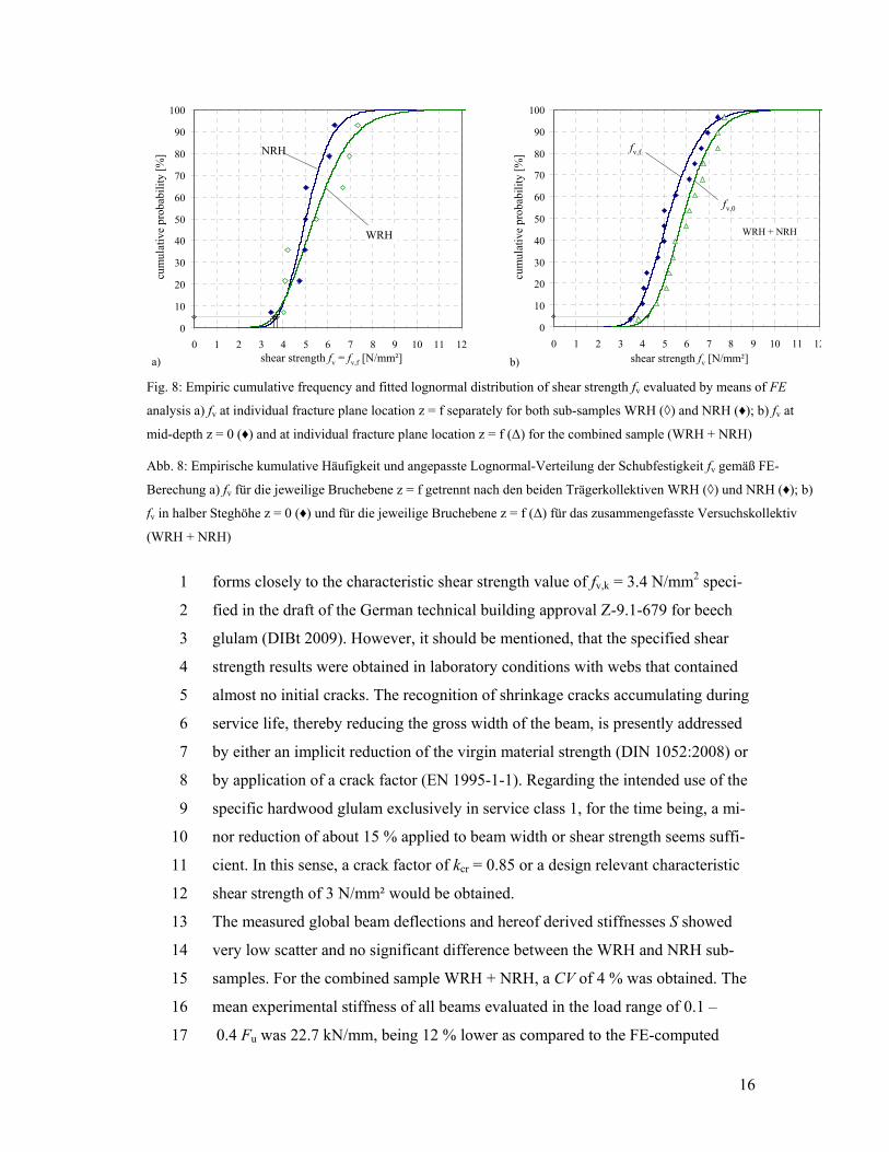
16
forms closely to the characteristic shear strength value of fv,k = 3.4 N/mm2 speci-1
fied in the draft of the German technical building approval Z-9.1-679 for beech 2
glulam (DIBt 2009). However, it should be mentioned, that the specified shear 3
strength results were obtained in laboratory conditions with webs that contained 4
almost no initial cracks. The recognition of shrinkage cracks accumulating during 5
service life, thereby reducing the gross width of the beam, is presently addressed 6
by either an implicit reduction of the virgin material strength (DIN 1052:2008) or 7
by application of a crack factor (EN 1995-1-1). Regarding the intended use of the 8
specific hardwood glulam exclusively in service class 1, for the time being, a mi-9
nor reduction of about 15 % applied to beam width or shear strength seems suffi-10
cient. In this sense, a crack factor of kcr = 0.85 or a design relevant characteristic 11
shear strength of 3 N/mm² would be obtained. 12
The measured global beam deflections and hereof derived stiffnesses S showed 13
very low scatter and no significant difference between the WRH and NRH sub-14
samples. For the combined sample WRH + NRH, a CV of 4 % was obtained. The 15
mean experimental stiffness of all beams evaluated in the load range of 0.1 –16
0.4 Fu was 22.7 kN/mm, being 12 % lower as compared to the FE-computed 17
0
10
20
30
40
50
60
70
80
90
100
0 1 2 3 4 5 6 7 8 9 10 11 12shear strength f v [N/mm²]
cum
ulat
ive
prob
abili
ty [%
]NRH
WRH
a)
cum
ulat
ive
prob
abili
ty [%
]
shear strength fv = fv,f [N/mm²]
0
10
20
30
40
50
60
70
80
90
100
0 1 2 3 4 5 6 7 8 9 10 11 12shear strength f v [N/mm²]
cum
ulat
ive
prob
abili
ty [%
]
fv,0
fv,f
b)
cum
ulat
ive
prob
abili
ty [%
]
shear strength fv [N/mm²]
WRH + NRH
Fig. 8: Empiric cumulative frequency and fitted lognormal distribution of shear strength fv evaluated by means of FE
analysis a) fv at individual fracture plane location z = f separately for both sub-samples WRH (◊) and NRH (♦); b) fv at
mid-depth z = 0 (♦) and at individual fracture plane location z = f (Δ) for the combined sample (WRH + NRH)
Abb. 8: Empirische kumulative Häufigkeit und angepasste Lognormal-Verteilung der Schubfestigkeit fv gemäß FE-
Berechung a) fv für die jeweilige Bruchebene z = f getrennt nach den beiden Trägerkollektiven WRH (◊) und NRH (♦); b)
fv in halber Steghöhe z = 0 (♦) und für die jeweilige Bruchebene z = f (Δ) für das zusammengefasste Versuchskollektiv
(WRH + NRH)
17
value specified in 3.1.2. The obtained agreement is still satisfactory; nevertheless, 1
the reasons for the stated discrepancy will be investigated further. 2
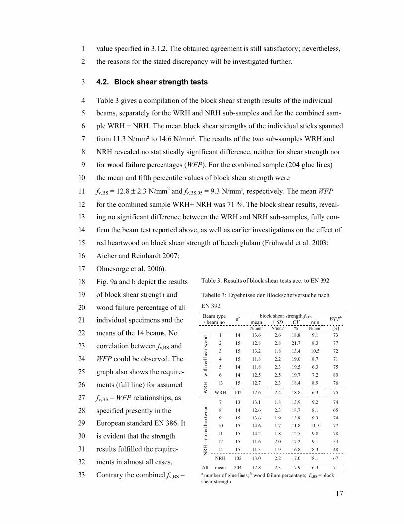
4.2. Block shear strength tests 3
Table 3 gives a compilation of the block shear strength results of the individual 4
beams, separately for the WRH and NRH sub-samples and for the combined sam-5
ple WRH + NRH. The mean block shear strengths of the individual sticks spanned 6
from 11.3 N/mm² to 14.6 N/mm². The results of the two sub-samples WRH and 7
NRH revealed no statistically significant difference, neither for shear strength nor 8
for wood failure percentages (WFP). For the combined sample (204 glue lines) 9
the mean and fifth percentile values of block shear strength were 10
fv,BS = 12.8 ± 2.3 N/mm2 and fv,BS,05 = 9.3 N/mm², respectively. The mean WFP 11
for the combined sample WRH+ NRH was 71 %. The block shear results, reveal-12
ing no significant difference between the WRH and NRH sub-samples, fully con-13
firm the beam test reported above, as well as earlier investigations on the effect of 14
red heartwood on block shear strength of beech glulam (Frühwald et al. 2003; 15
Aicher and Reinhardt 2007; 16
Ohnesorge et al. 2006). 17
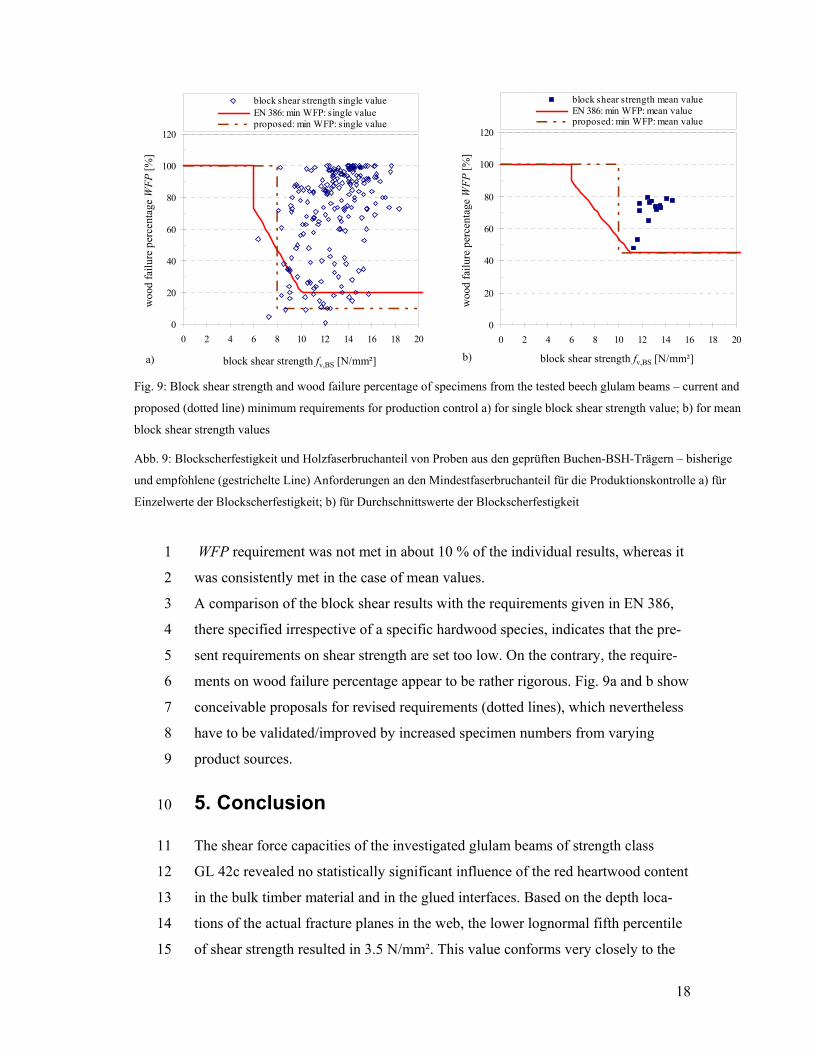
Fig. 9a and b depict the results 18
of block shear strength and 19
wood failure percentage of all 20
individual specimens and the 21
means of the 14 beams. No 22
correlation between fv,BS and 23
WFP could be observed. The 24
graph also shows the require-25
ments (full line) for assumed 26
fv,BS – WFP relationships, as 27
specified presently in the 28
European standard EN 386. It 29
is evident that the strength 30
results fulfilled the require-31
ments in almost all cases. 32
Contrary the combined fv,BS –33
Table 3: Results of block shear tests acc. to EN 392
Tabelle 3: Ergebnisse der Blockscherversuche nach
EN 392
Beam type / beam no na block shear strength fv,BS WFPb mean ± SD CV min
N/mm² N/mm² % N/mm² [%]
WR
H –
with
red
hear
twoo
d 1 14 13.6 2.6 18.8 9.1 73 2 15 12.8 2.8 21.7 8.3 77 3 15 13.2 1.8 13.4 10.5 72 4 15 11.8 2.2 19.0 8.7 71 5 14 11.8 2.3 19.5 6.3 75 6 14 12.5 2.5 19.7 7.2 80 13 15 12.7 2.3 18.4 8.9 76
WRH 102 12.6 2.4 18.8 6.3 75
NR
H –
no
red
hear
twoo
d
7 13 13.1 1.8 13.9 9.2 74 8 14 12.6 2.3 18.7 8.1 65 9 15 13.6 1.9 13.8 9.3 74 10 15 14.6 1.7 11.8 11.5 77 11 15 14.2 1.8 12.5 9.8 78 12 15 11.6 2.0 17.2 9.1 53 14 15 11.3 1.9 16.8 8.3 48
NRH 102 13.0 2.2 17.0 8.1 67
All mean 204 12.8 2.3 17.9 6.3 71 a number of glue lines; b wood failure percentage; fv,BS = block shear strength
18
WFP requirement was not met in about 10 % of the individual results, whereas it 1
was consistently met in the case of mean values. 2
A comparison of the block shear results with the requirements given in EN 386, 3
there specified irrespective of a specific hardwood species, indicates that the pre-4
sent requirements on shear strength are set too low. On the contrary, the require-5
ments on wood failure percentage appear to be rather rigorous. Fig. 9a and b show 6
conceivable proposals for revised requirements (dotted lines), which nevertheless 7
have to be validated/improved by increased specimen numbers from varying 8
product sources. 9
5. Conclusion 10
The shear force capacities of the investigated glulam beams of strength class 11
GL 42c revealed no statistically significant influence of the red heartwood content 12
in the bulk timber material and in the glued interfaces. Based on the depth loca-13
tions of the actual fracture planes in the web, the lower lognormal fifth percentile 14
of shear strength resulted in 3.5 N/mm². This value conforms very closely to the 15
0
20
40
60
80
100
120
0 2 4 6 8 10 12 14 16 18 20
block shear strength fv,BS [N/mm²]
woo
d fa
ilure
per
cent
age
WFP
[%]
block shear strength single value EN 386: min WFP: single value proposed: min WFP: single value
woo
d fa
ilure
per
cent
age
WFP
[%]
block shear strength fv,BS [N/mm²]a)
0
20
40
60
80
100
120
0 2 4 6 8 10 12 14 16 18 20
block shear strength fv,BS [N/mm²]
woo
d fa
ilure
per
cent
age
WFP
[%]
block shear strength mean value EN 386: min WFP: mean value proposed: min WFP: mean value
woo
d fa
ilure
per
cent
age
WFP
[%]
block shear strength fv,BS [N/mm²]b)
Fig. 9: Block shear strength and wood failure percentage of specimens from the tested beech glulam beams – current and
proposed (dotted line) minimum requirements for production control a) for single block shear strength value; b) for mean
block shear strength values
Abb. 9: Blockscherfestigkeit und Holzfaserbruchanteil von Proben aus den geprüften Buchen-BSH-Trägern – bisherige
und empfohlene (gestrichelte Line) Anforderungen an den Mindestfaserbruchanteil für die Produktionskontrolle a) für
Einzelwerte der Blockscherfestigkeit; b) für Durchschnittswerte der Blockscherfestigkeit
19
characteristic shear strength of 3.4 N/mm² given in the draft of the German tech-1
nical approval Z-9.1-679 for beech glulam. 2
The block shear tests, similar to the beam tests, showed the red heartwood content 3
of the glued laminations as having no effect, neither on shear strength nor on 4
wood failure percentage. A comparison of the block shear results with EN 386 5
indicates that the present requirements on block shear strength in the European 6
standard are not applicable to beech glulam. This should be confirmed by further 7
investigations. 8
Acknowledgements 9
This study was performed at the Institute of Forest Utilization and Work Science of the University 10 of Freiburg and at MPA University of Stuttgart, Department of Timber Constructions, in the frame 11 of the EU-CRAFT-project “Innovation for Beech” and the BMBF project “Large dimensioned 12 timber, sub-work package hardwood products”. Financial support provided by the European 13 Commission as well as by the Federal Ministry of Education and Research (BMBF) is gratefully 14 acknowledged. Many thanks are indebted to the glulam manufacturer Burgbacher Holztechnologie 15 GmbH for the production of the glulam beams and its valuable contributions to the study. 16
6. References 17
6.1. Referred standards and technical approvals 18
ASTM D143 – 94 (2007) Standard Test Methods for Small Clear Specimens of Timber. ASTM 19 International, West Conshohocken, PA, DOI: 10.1520/D0143-94R07 20 ASTM D2555 (2006) Standard Practice for Establishing Clear Wood Strength Values. ASTM 21 International, West Conshohocken, PA, DOI: 10.1520/D2555-06 22 ASTM D2915 (2003) Standard Practice for Evaluating Allowable Properties for Grades of Struc-23 tural Lumber, West Conshohocken, PA, DOI: 10.1520/D2915-03 24 ASTM D3737 (2008) Standard Practice for Establishing Allowable Properties for Structural Glued 25 Laminated Timber (Glulam). ASTM International, West Conshohocken, PA, DOI: 26 10.1520/D3737-08 27 DIBt (2009) Allgemeine Bauaufsichtliche Zulassung (Entwurf) Z-9.1-679; Zulassungsgegenstand: 28 BS-Holz aus Buche und BS-Holz Hybridträger. Antragsteller: Studiengemeinschaft Holzleimbau 29 e.V., Wuppertal 30 DIN 4074-5:2003 Strength grading of wood – Part 5: Sawn hardwood 31 DIN 68140-1:1998 Wood Finger jointing – Part 1: Finger jointing of softwood for load bearing 32 EN 13183-1:2002 Moisture content of a piece of sawn timber – Part 1: Determination by oven dry 33 method 34
20
EN 1995-1-1:2004/A1:2008 Eurocode 5 – Design of timber structures – part 1-1: General – Com-1 mon rules and rules for buildings 2 EN 301:2006 Adhesives, phenolic and aminoplastic, for load-bearing timber structures - Classifi-3 cation and performance requirements 4 EN 386:2001 Glued laminated timber – Performance requirements and minimum production re-5 quirements 6 EN 392:1995 Glued laminated timber – Shear tests of glue lines 7 EN 408:2003 Timber structures – Structural timber and glued laminated timber – Determination of 8 some physical and mechanical properties 9 HKS:1969 Gesetz über gesetzliche Handelsklassen für Rohholz vom 25. Februar 1969. BGBI. I 10 S.149. Gesetzliche Handelsklassensortierung für Rohholz mit Ergänzungsbestimmungen für 11 Baden-Württemberg, vom 1.10.1983 12 ISO 3131:1975 Wood – Determination of density for physical and mechanical tests 13
6.2. Literature 14
Aicher S, Höfflin L, Behrens W (2001) A study on tension strength of finger joints in beech wood 15 laminations. Otto-Graf-J 12:169-186 16 Aicher S, Reinhardt HW (2007) Delamination properties and shear strength of glued beech wood 17 laminations with red heartwood. Holz Roh-Werkst 64:125–136 18 Bernasconi A (2004) Verleimung von Laubholz für den tragenden Einsatz. Schweiz. Z. Forstwiss. 19 155 (12):533-539 20 Blaß HJ, Denzler J, Frese M, Glos P, Linsenmann P (2005) Biegefestigkeit von Brettschichtholz 21 aus Buche. Forschungsbericht Versuchsanstalt Stahl, Holz und Steine, Abt Ingenieurholzbau, 22 Universität TH Karlsruher Berichte Ingenieurholzbau, Bd 1, Universitätsverlag Karlsruhe 23 Egner K, Kolb H (1966) Geleimte Träger und Binder aus Buchenholz. Bauen mit Holz 68 (4):147-24 154 25 Frese M (2006) Die Biegefestigkeit von Brettschichtholz aus Buche – experimentelle und 26 numerische Untersuchungen zum Laminierungseffekt. Diss, Karlsruher Berichte Ingenieurholz-27 bau, Bd 5, Universitätsverlag Karlsruhe 28 Frese M, Blaß HJ (2005) Beech glulam strength classes. Int Council for Research and Innovation 29 in Building and Construction. Working Commission W18 – Timber Structures. Proc Meeting 38, 30 Paper CIB-W18/38-6-2, Karlsruhe, Germany 31 Frühwald A, Ressel J, Bernasconi A ,Becker P, Pitzner B, Wonnemann R, Mantau U, Sörgel C, 32 Thoroe C, Dieter M, Englert H (2003): Hochwertiges Brettschichtholz aus Buchenholz. Res Rep 33 Bundesforschungsanstalt für Forst- und Holzwirtschaft, Hamburg 34 Gehri E (1980) Möglichkeiten des Einsatzes von Buchenholz für Tragkonstruktionen. Schweizer 35 Bauwirtschaft 56:17-21 36 Gehri E (1985) High performance jointing techniques - State of art and development. (In German), 37 Holz Roh- Werkst 43:83-88 38
21
Glos P, Lederer B (2000) Sortierung von Buchen- und Eichenschnittholz nach der Tragfähigkeit 1 und Bestimmung der zugehörigen Festigkeits- und Steifigkeitswerte. Res Rep 98508, 2 Holzforschung, Technische Universität München 3 Ilic J (2003) Dynamic MOE of 55 species using small wood beams. Holz Roh- Werkst 61:167-172 4 Jegley D, Williams J (1988) Multiple-span beam shear test for composite laminates. NASA-LAR-5 13605 6 Keenan FJ, Kryla J, Kyokong B (1985) Shear strength of spruce glued - laminated timber beams. 7 Canadian J. Civil Eng 12(3):661–672 8 Kolb H (1968) Biegeversuche und Prüfung des Brandverhaltens an Trägern aus verleimten 9 Buchenschälfurnieren. Holz Roh- Werkst 26:277-283 10 Korin U (1996) Determination of the Shear Strength of Timber. In: Proc Int Wood Eng Conf 96, 11 Vol 2:91-95, New Orleans, USA 12 Lam F, Yee H, Barrett JD (1995) Shear strength of Canadian softwood structural lumber. Int 13 Council for Research and Innovation in Building and Construction. Working Commission W18 – 14 Timber Structures. Proc Meeting 28, Paper CIB-W18/28-6-1, Copenhagen, Denmark 15 Ohnesorge D, Richter K, Seeling U (2006) Glueability of Beech wood containing red heartwood. 16 Proc 5th Int Symp Wood Structure and Properties, Sliac - Sielnica, Slovakia 17 Ohnesorge D, Richter K, Becker G, Aicher S (2008) Adhesion behaviour of glued laminated tim-18 ber from European Beech. Proc Conf COST E34 “Bonding of Timber – Enhancing bond line per-19 formance”, Sopron, Hungary 20 Pöhler E, Klingner R, Künniger T (2006) Beech (Fagus sylvatica L.) - Technological properties, 21 adhesion behaviour and colour stability with and without coatings of the red heartwood. Ann For 22 Sci 63 (2):129-137 23 Schickhofer G (2001) Determination of shear strength values for GLT using visual and machine 24 graded spruce laminations. Int Council for Research and Innovation in Building and Construction. 25 Working Commission W18 – Timber Structures. Proc Meeting 34, Paper CIB-W18/34-12-6, Ven-26 ice, Italy 27 Schickhofer G, Obermayr B (1998) Development of an optimized test configuration to determine 28 shear strength of glued laminated timber. Int Council for Research and Innovation in Building and 29 Construction. Working Commission W18 – Timber Structures. Proc Meeting 31, Paper CIB-30 W18/31-21-1, Savonlinna, Finland 31 Soltis LA, Rammer DR (1994) Shear strength of unchecked glued-laminated beams. Forest Prod J 32 44 (1): 51-57 33 Yeh B, Williamson TG (2001) Evaluation of glulam shear strength using a fullsize four-point test 34 method. Int Council for Research and Innovation in Building and Construction. Working Commis-35 sion W18 – Timber Structures. Proc Meeting 34, Paper CIB-W18/34-12-2, Venice, Italy 36