shape from shading - iit madras cse dept.vplab/courses/cv_dip/pdf/shapefromshading.pdf · shape...
TRANSCRIPT
Shape from ShadingShape from Shading
Computer VisionCS635
Dr. Sukhendu Das,Dept. of Computer Science & Engg.
IntroductionIntroduction• An image is essentially 2D where as the world
is 3D• The human visual system recovers shapes of
objects in a 3D scene from a 2D image by a number of cues• Motion parallax• Binocular disparity
• But even a single image gives a lot of information about shape of an object. Where is the hidden information?
• Some examples to illustrate the point previously mentioned
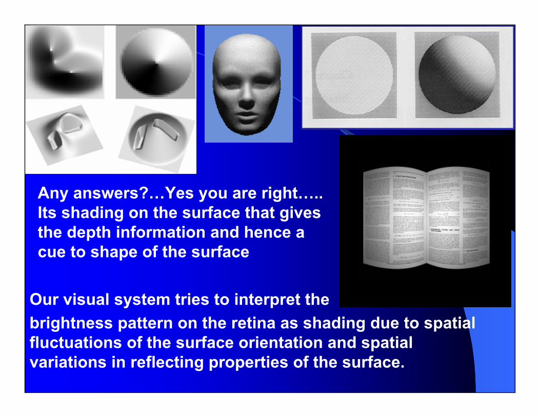
Any answers?…Yes you are right….. Its shading on the surface that gives the depth information and hence a cue to shape of the surface
Our visual system tries to interpret the brightness pattern on the retina as shading due to spatial fluctuations of the surface orientation and spatial variations in reflecting properties of the surface.

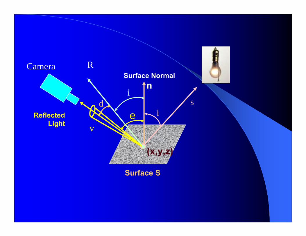
The Reflectance mapThe Reflectance map
Surface S
Surface Normaln
v
Reflected Light
sIncident Light
(x,y,z)
ie
Camera • S – surface• (x,y,z) – Point on the
surface• n – surface normal• s – source direction• v – viewing direction• i – incident angle• e – emergent angle• (x’,y’) – Points on the
image plane• a(x,y,z) – Incident
brightness at each point on the 3D scene
• Φ(n,s,v) – the reflecting properties of the surface in scene),,(),,(),( '' vsnzyxkayxI φ=
Image intensity can be related to that in the scene by this equation
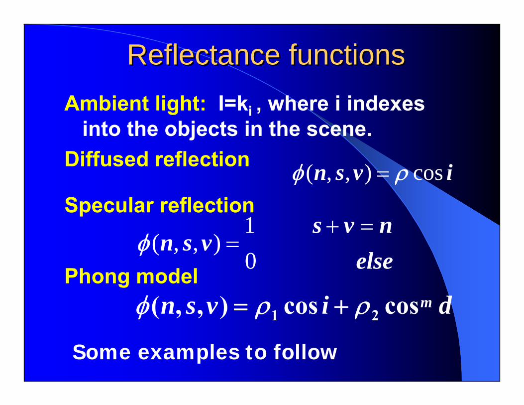
Reflectance functionsReflectance functionsAmbient light: I=ki , where i indexes
into the objects in the scene.Diffused reflection ivsn cos),,( ρφ =
elsenvs
vsn 0
1),,(
=+=φ
divsn mcoscos),,( 21 ρρφ +=
Specular reflection
Phong model
Some examples to follow
Surface S
Surface Normaln
Reflected Light
(x,y,z)
ie
Camera R
id s
v

REFLECTANCE MODELSREFLECTANCE MODELS
albedo
Diffuse albedo Specular albedo
PHONG MODEL
ρ1=0.3, ρ2 =0.7,m=2 ρ1 =0.7, ρ2 =0.3, m=0.5
LAMBERTIAN MODELivsn cos),,( ρφ =
divsn mcoscos),,( 21 ρρφ +=
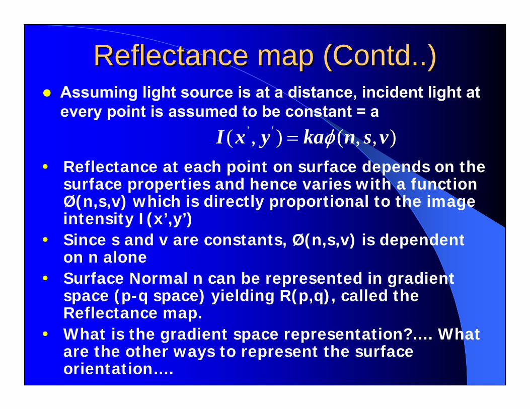
Reflectance map (Contd..)Reflectance map (Contd..)Assuming light source is at a distance, incident light at every point is assumed to be constant = a
),,(),( '' vsnkayxI φ=• Reflectance at each point on surface depends on the
surface properties and hence varies with a function Ø(n,s,v) which is directly proportional to the image intensity I(x’,y’)
• Since s and v are constants, Ø(n,s,v) is dependent on n alone
• Surface Normal n can be represented in gradient space (p-q space) yielding R(p,q), called the Reflectance map.
• What is the gradient space representation?…. What are the other ways to represent the surface orientation….
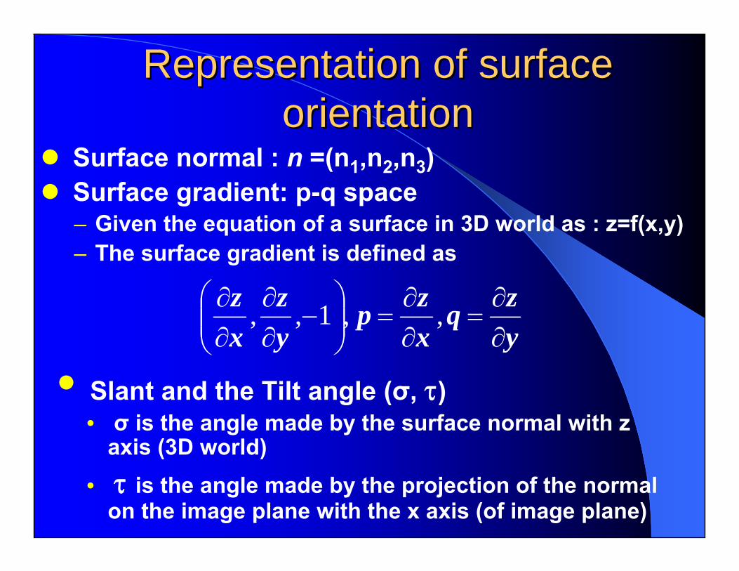
Representation of surface Representation of surface orientationorientation
Surface normal : n =(n1,n2,n3)Surface gradient: p-q space– Given the equation of a surface in 3D world as : z=f(x,y)– The surface gradient is defined as
yzq
xzp
yz
xz
∂∂
=∂∂
=⎟⎟⎠
⎞⎜⎜⎝
⎛−
∂∂
∂∂ ,,1,,
• Slant and the Tilt angle (σ, τ)• σ is the angle made by the surface normal with z
axis (3D world) • τ is the angle made by the projection of the normal
on the image plane with the x axis (of image plane)

Slant and the tilt angle Slant and the tilt angle
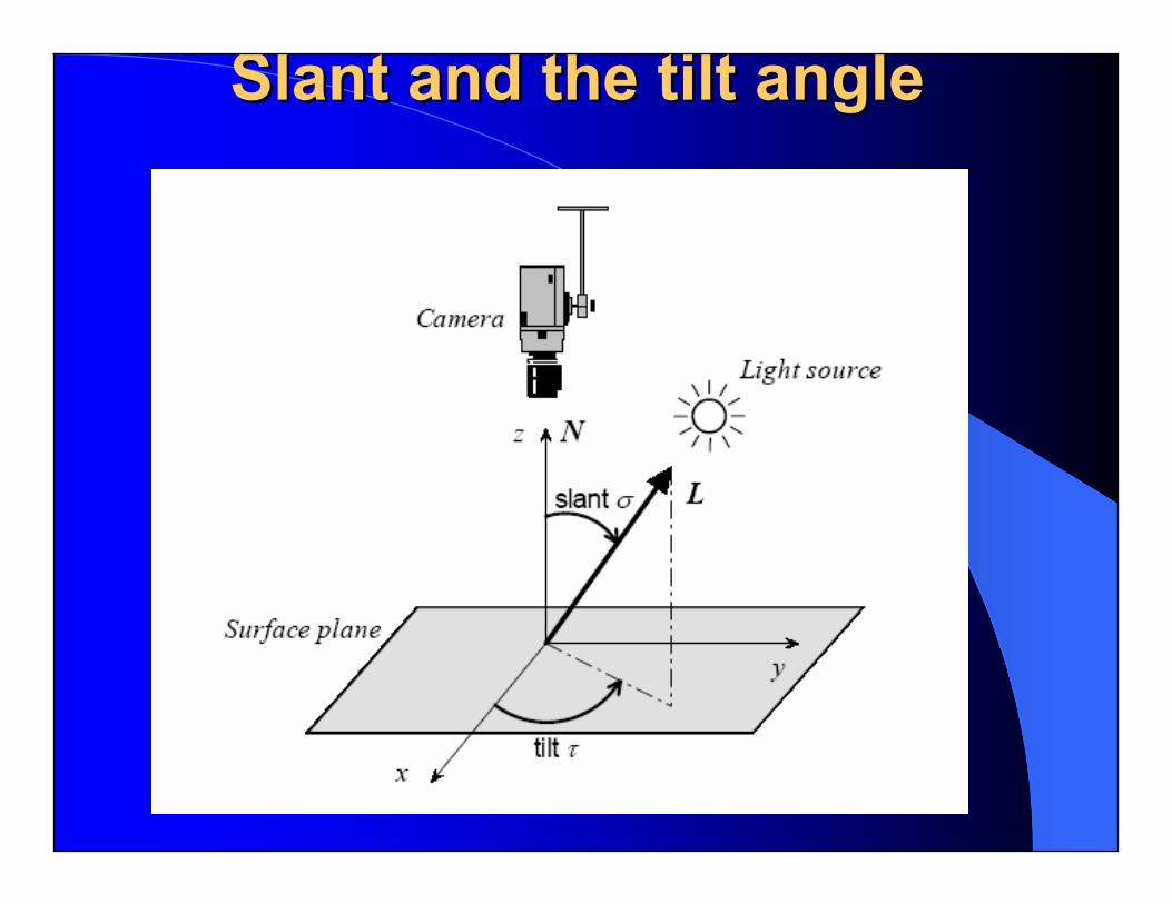
Slant and the tilt angleSlant and the tilt angle

Slant and the tilt angle

Gradient space representationGradient space representation
A plane parallel to x-y plane will have the gradient 0 in both x and y directions
From p and q the equation of a plane can be recovered as
cqypxz ++=
1 23
4 5 p
q
x
y
z
1’ 2’
3’
4’
5’
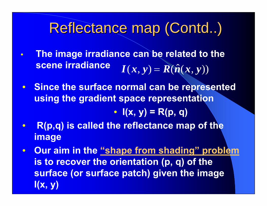
Reflectance map (Contd..)Reflectance map (Contd..)• The image irradiance can be related to the
scene irradiance )),(ˆ(),( yxnRyxI =
• Since the surface normal can be represented using the gradient space representation
• I(x, y) = R(p, q)• R(p,q) is called the reflectance map of the
image • Our aim in the “shape from shading” problem
is to recover the orientation (p, q) of the surface (or surface patch) given the image I(x, y)
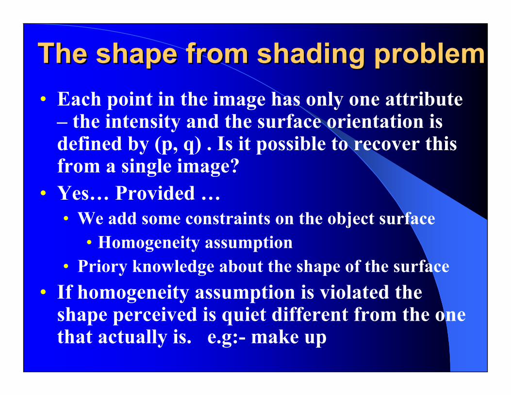
The shape from shading problemThe shape from shading problem• Each point in the image has only one attribute
– the intensity and the surface orientation is defined by (p, q) . Is it possible to recover this from a single image?
• Yes… Provided …• We add some constraints on the object surface
• Homogeneity assumption• Priory knowledge about the shape of the surface
• If homogeneity assumption is violated the shape perceived is quiet different from the one that actually is. e.g:- make up

The shape from shading The shape from shading problem (Contd…)problem (Contd…)
To formulate the shape from shading problem 2 issues need to be solved– Position of a point in the image with respect to
its position in the 3D SceneProjective Geometry is the answer
– What determines the brightness of each point on the surface
Reflecting properties of the surface (BRDF)Illumination model used
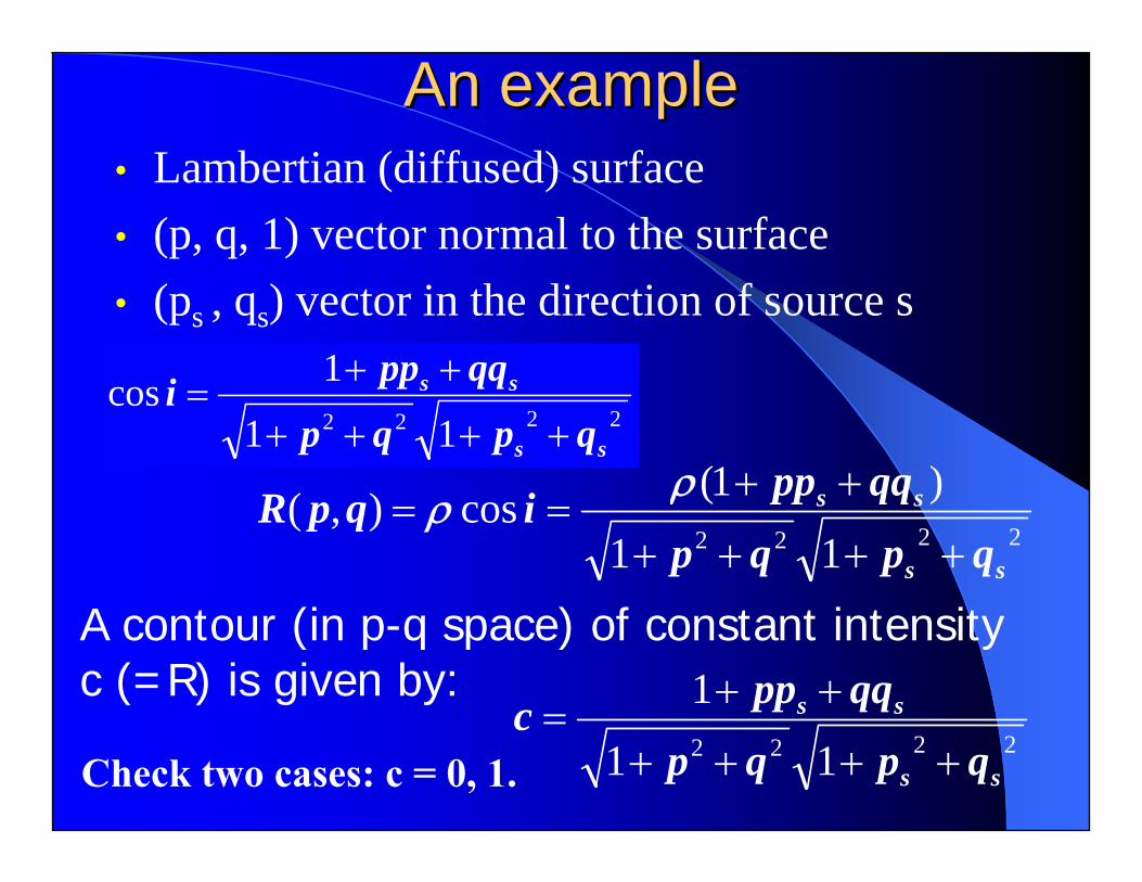
An exampleAn example• Lambertian (diffused) surface• (p, q, 1) vector normal to the surface• (ps , qs) vector in the direction of source s
2222 11
1cosss
ss
qpqp
qqppi++++
++=
2222 11
)1(cos),(ss
ss
qpqp
qqppiqpR++++
++==
ρρ
2222 11
1
ss
ss
qpqp
qqppc++++
++=
A contour (in p-q space) of constant intensity c (=R) is given by:
Check two cases: c = 0, 1.
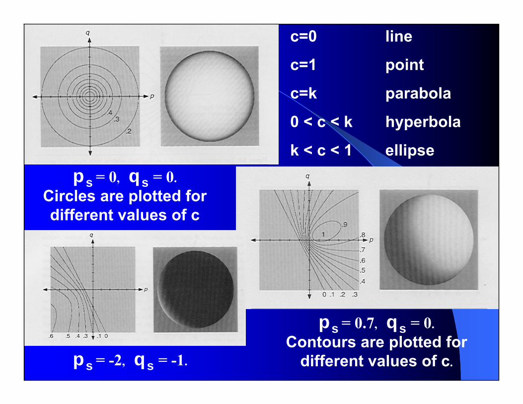
ps = 0, qs = 0.Circles are plotted for different values of c
ps = 0.7, qs = 0.Contours are plotted for
different values of c.ps = -2, qs = -1.
c=0 line
c=1 point
c=k parabola
0 < c < k hyperbola
k < c < 1 ellipse
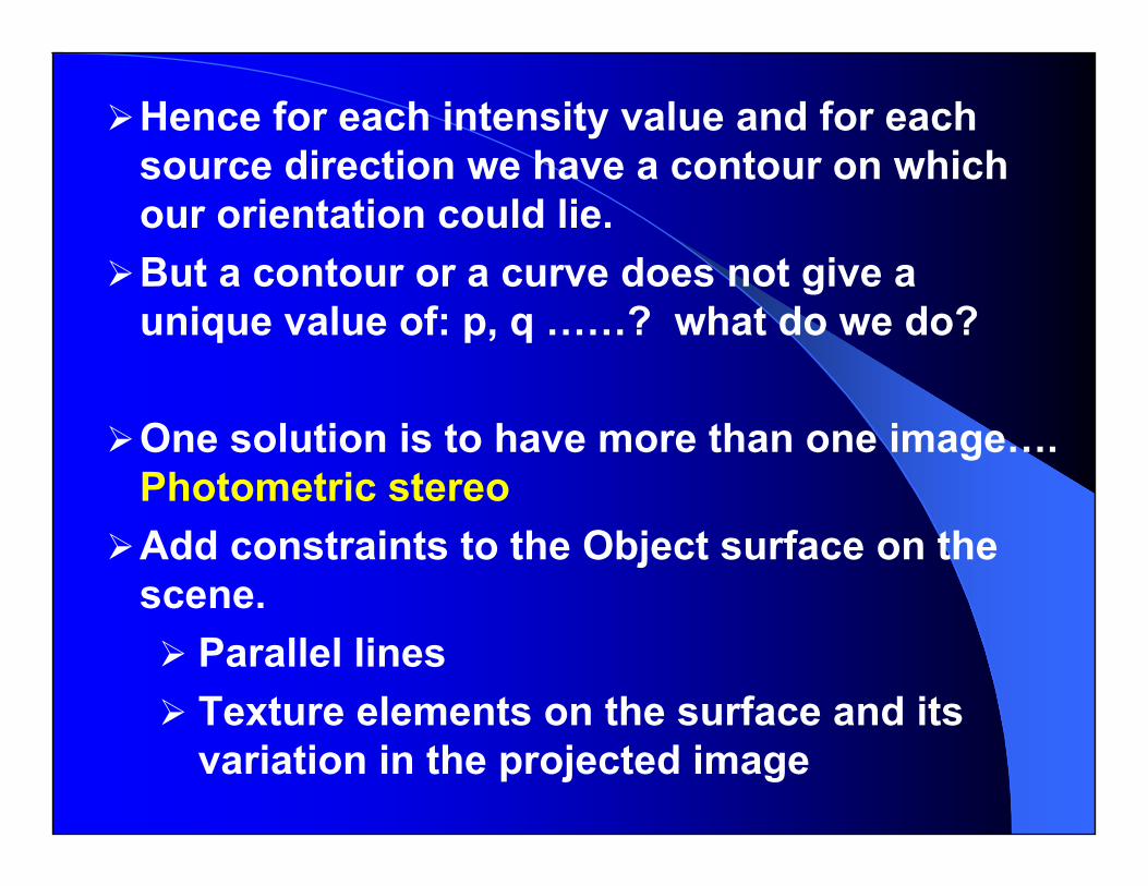
Hence for each intensity value and for each source direction we have a contour on which our orientation could lie.But a contour or a curve does not give a unique value of: p, q ……? what do we do?
One solution is to have more than one image…. Photometric stereoAdd constraints to the Object surface on the scene.
Parallel lines Texture elements on the surface and its variation in the projected image

Photometric stereoPhotometric stereo
• Use more than one image. • Find the contours or curves for
each one.• The intersection of 2 curves
gives 2 such possible points• Intersection of 3 or more curves
will give one unique value for (p, q)
R1(p,q)
R2(p,q)R3(p,q)
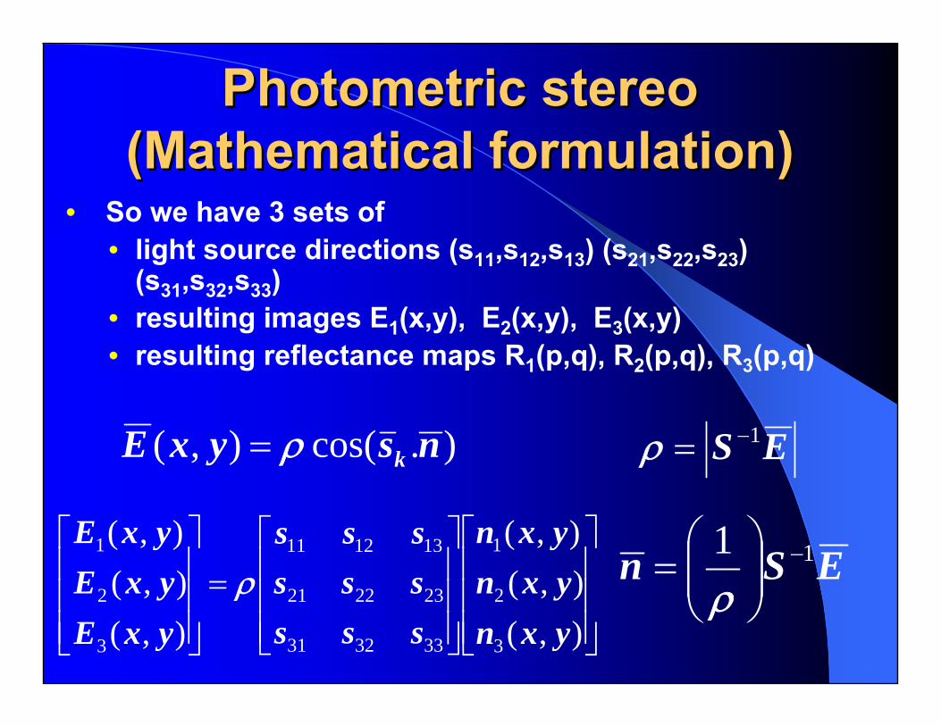
Photometric stereo Photometric stereo (Mathematical formulation)(Mathematical formulation)
• So we have 3 sets of • light source directions (s11,s12,s13) (s21,s22,s23)
(s31,s32,s33) • resulting images E1(x,y), E2(x,y), E3(x,y)• resulting reflectance maps R1(p,q), R2(p,q), R3(p,q)
).cos(),( nsyxE kρ=
⎥⎥⎥
⎦
⎤
⎢⎢⎢
⎣
⎡
⎥⎥⎥
⎦
⎤
⎢⎢⎢
⎣
⎡=
⎥⎥⎥
⎦
⎤
⎢⎢⎢
⎣
⎡
),(),(),(
),(),(),(
3
2
1
333231
232221
131211
3
2
1
yxnyxnyxn
sssssssss
yxEyxEyxE
ρ
ES 1−=ρ
ESn 11 −⎟⎟⎠
⎞⎜⎜⎝
⎛=
ρ
Adding Geometric Constraints Adding Geometric Constraints to the sceneto the scene
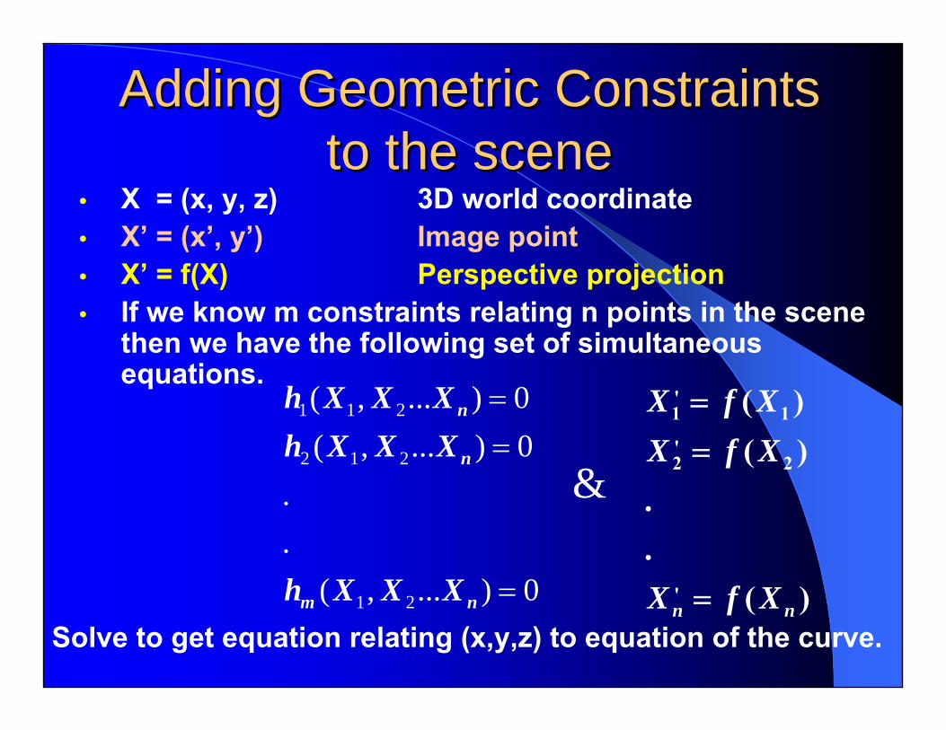
• X = (x, y, z) 3D world coordinate• X’ = (x’, y’) Image point• X’ = f(X) Perspective projection• If we know m constraints relating n points in the scene
then we have the following set of simultaneous equations.
0)...,(..
0)...,(0)...,(
21
212
211
=
==
nm
n
n
XXXh
XXXhXXXh
&
)(..
)()(
'
2'2
1'1
nn XfX
XfXXfX
=
==
Solve to get equation relating (x,y,z) to equation of the curve.
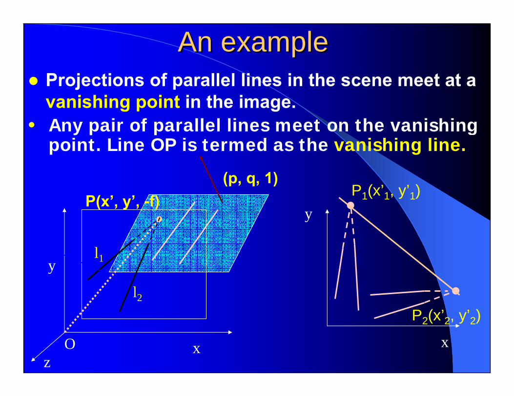
An exampleAn exampleProjections of parallel lines in the scene meet at a vanishing point in the image.
x
y
z
(p, q, 1)P(x’, y’, -f)
l2
l1
x
yP1(x’1, y’1)
P2(x’2, y’2)
• Any pair of parallel lines meet on the vanishing point. Line OP is termed as the vanishing line.
O
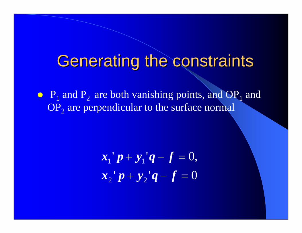
Generating the constraintsGenerating the constraints
P1 and P2 are both vanishing points, and OP1 and OP2 are perpendicular to the surface normal
0'',0''
22
11
=−+=−+
fqypxfqypx
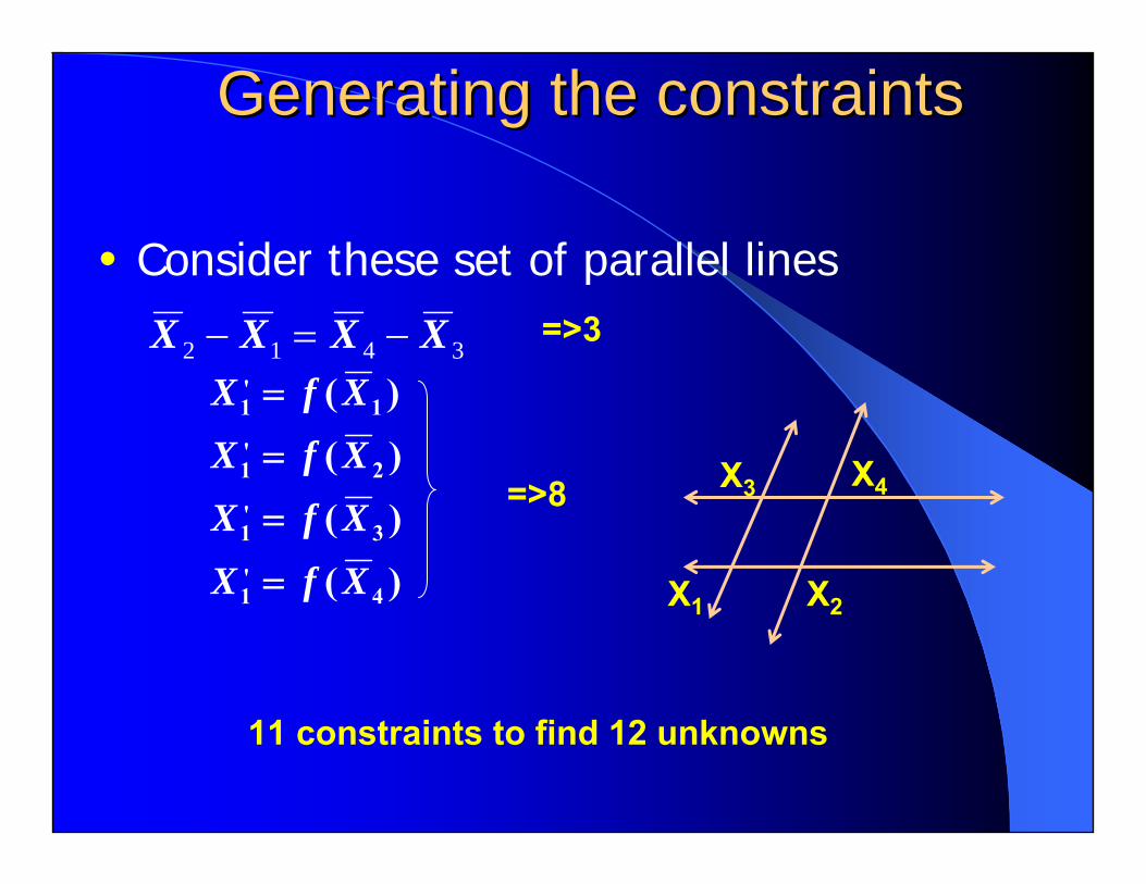
Generating the constraintsGenerating the constraints
X3 X4
X1 X2
3412 XXXX −=−
)()()()(
4'1
3'1
2'1
1'1
XfXXfXXfXXfX
=
=
=
=
=>3
=>8
11 constraints to find 12 unknowns
• Consider these set of parallel lines

End of lectures on End of lectures on
Shape from ShadingShape from Shading
Slides courtesy: Shivani G. Rao