shale gas in the uk -...
TRANSCRIPT
1
© 2
016
Gaf
fney
, Clin
e &
Ass
ocia
tes.
All
Rig
hts
Res
erve
d.
© 2016 Gaffney, Cline & Associates. All rights reserved. Terms and conditions of use: by accepting this document, the recipient agrees that the document together with all information included therein is the confidential and proprietary property of
Gaffney, Cline & Associates and includes valuable trade secrets and/or proprietary information of Gaffney, Cline & Associates (collectively "information"). Gaffney, Cline & Associates retains all rights under copyright laws and trade secret laws of the
United States of America and other countries. The recipient further agrees that the document may not be distributed, transmitted, copied or reproduced in whole or in part by any means, electronic, mechanical, or otherwise, without the express prior
written consent of Gaffney, Cline & Associates, and may not be used directly or indirectly in any way detrimental to Gaffney, Cline & Associates’ interest.
Séadhna Wilson and Adrian Topham
27th April 2016
Shale Gas in the UK London Engineering Group

2
© 2
016
Gaf
fney
, Clin
e &
Ass
ocia
tes.
All
Rig
hts
Res
erve
d.
Disclaimer
This presentations has been prepared exclusively for
discussion purposes during this event. The materials
presented should not be understood as GCA forecasts or
predictions of future industry conditions and they should not
be understood as a specific recommendation in respect of
any particular decision or course of action.

3
© 2
016
Gaf
fney
, Clin
e &
Ass
ocia
tes.
All
Rig
hts
Res
erve
d.
▪ Introduction to shale gas and oil
▪ Myths and reality
▪ Moving from conventional to unconventional in the UK
▪ UK regulations and risk management
▪ Key messages
Contents
4
© 2
016
Gaf
fney
, Clin
e &
Ass
ocia
tes.
All
Rig
hts
Res
erve
d.
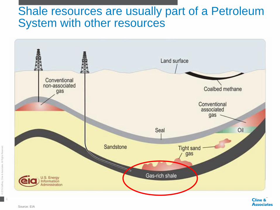
Shale resources are usually part of a Petroleum System with other resources
Source: EIA

5
© 2
016
Gaf
fney
, Clin
e &
Ass
ocia
tes.
All
Rig
hts
Res
erve
d.
Shale has little to no porous space meaning oil and gas cannot flow freely
▪ This means there is little space
between grains
▪ This means fluids do not move
easily through the rock
▪ Conventional reservoirs have
permeabilities of 1-1000mD
Shale has low porosity (<10%) Shale has low permeability (<0.1mD)
Source: OGP
6
© 2
016
Gaf
fney
, Clin
e &
Ass
ocia
tes.
All
Rig
hts
Res
erve
d.
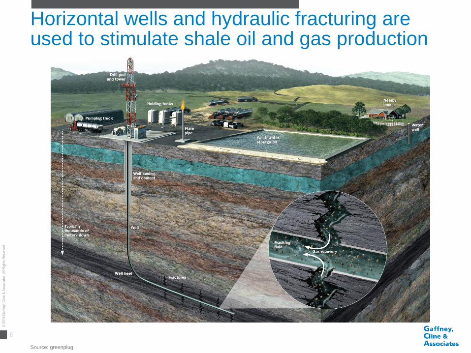
Horizontal wells and hydraulic fracturing are used to stimulate shale oil and gas production
Source: greenplug

7
© 2
016
Gaf
fney
, Clin
e &
Ass
ocia
tes.
All
Rig
hts
Res
erve
d.
▪ Introduction to shale gas and oil
▪ Myths and reality
▪ Moving from conventional to unconventional in the UK
▪ UK regulations and risk management
▪ Key messages
Contents
8
© 2
016
Gaf
fney
, Clin
e &
Ass
ocia
tes.
All
Rig
hts
Res
erve
d.
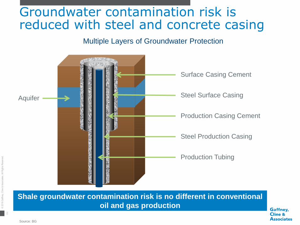
Groundwater contamination risk is reduced with steel and concrete casing
Source: BG
Surface Casing Cement
Steel Surface Casing
Production Casing Cement
Steel Production Casing
Production Tubing
Aquifer
Multiple Layers of Groundwater Protection
Shale groundwater contamination risk is no different in conventional
oil and gas production

9
© 2
016
Gaf
fney
, Clin
e &
Ass
ocia
tes.
All
Rig
hts
Res
erve
d.
Hydraulic Fracturing at Preese hall caused a 2.3 ML earthquake
Sources: British Geological Society and “Preese Hall Shale Gas Fracturing – Review & Recommendations for Induced Seismic Mitigation”, Dr CA Green, Prof P Styles and DR BJ Baptie, 2012
Preese Hall
2.3 ML
Recorded UK Earthquakes, 2011 - 2016
Bubble size is
indicative of
magnitude
The UK has experience over 100 naturally occurring earthquakes of a
similar size to Preese Hall in the last five years
• Assessed maximum
earthquake of 3.0 ML – taken as
analogy with Coal Mining
Industry
• 3.0 ML at 2-3 km depth unlikely
to cause structural damage, but
is noticeable
• Similar earthquakes in UK have
caused superficial damage
DECC Commissioned Report Findings

10
© 2
016
Gaf
fney
, Clin
e &
Ass
ocia
tes.
All
Rig
hts
Res
erve
d.
Water and sand are the dominant ingredients in Preese Hall Hydraulic Fracturing fluid
Water 97.9%
Sand 2.0%
Friction Reducer - Polyacylamide
Emulsion in Hydrocarbon Oil
<0.1%
Tracer - Water with Sodium Salt
<0.01%
Additives 2.1%
Cuadrilla Preese Hall Hydraulic Fracturing Fluid Composition (% Volume)
In the UK all additives must be disclosed and approved by the
Environment Agency

11
© 2
016
Gaf
fney
, Clin
e &
Ass
ocia
tes.
All
Rig
hts
Res
erve
d.
Fracturing fluids in the USA have a diverse range of additives that are not always disclosed
Sources: “Assessment of the Potential Impacts of Hydraulic Fracturing for Oil and Gas on Drinking Water Resources – Executive Summary”, EPA, 2015
“Analysis of Hydraulic Fracturing Fluid Data from the FracFocus Chemical Disclosure Registry 1.0”, EPA, 2015
Gas Production Type
Chemical
Median concentration
in hydraulic fracturing
fluid (% by mass)
Hydrochloric acid 0.078
Methanol 0.002
Distillates, petroleum,
hydrotreated light 0.017
Isopropanol 0.0016
Water 0.18
Ethanol 0.0023
Propargyl alcohol 0.00007
Glutaraidehyde 0.0084
Ethylene glycol 0.0061
Citric acid 0.0017
Sodium hydroxide 0.0036
Peroxydisulfuric acid,
diammonium salt 0.0045
Fluid Additives in USA
Isolated cases exist where drinking water has been contaminated
• No evidence that hydraulic
fracturing led to widespread,
systemic impact on drinking
water
• Isolated cases exist where
drinking water has been
contaminated
• Insufficient data to determine
frequency of impacts
• One or more ingredients were
claimed confidential in more
than 70% of disclosures to
EPA
Excerpts from Conclusions of
2015 EPA Report

12
© 2
016
Gaf
fney
, Clin
e &
Ass
ocia
tes.
All
Rig
hts
Res
erve
d.
Shale gas extraction GHG emissions are comparable to conventional gas
Source: “Potential greenhouse gas emissions associated with shale gas extraction and use”, DECC, 2013
Selected Recommendations:
• Emissions should be kept as
low a level as is reasonably
practical (ALARP)
• Operators should monitor
their sites for GHG
emissions
• Shale gas production should
be accompanied by more
research into more effective
technologies, e.g.:
• Reduced emission
completion (REC)
• Self-healing cements
DECC 2012 Report on GHG Emissions from Shale Gas
13
© 2
016
Gaf
fney
, Clin
e &
Ass
ocia
tes.
All
Rig
hts
Res
erve
d.
▪ Introduction to shale gas and oil
▪ Myths and reality
▪ Moving from conventional to unconventional in the UK
▪ UK regulations and risk management
▪ Key messages
Contents
14
© 2
016
Gaf
fney
, Clin
e &
Ass
ocia
tes.
All
Rig
hts
Res
erve
d.
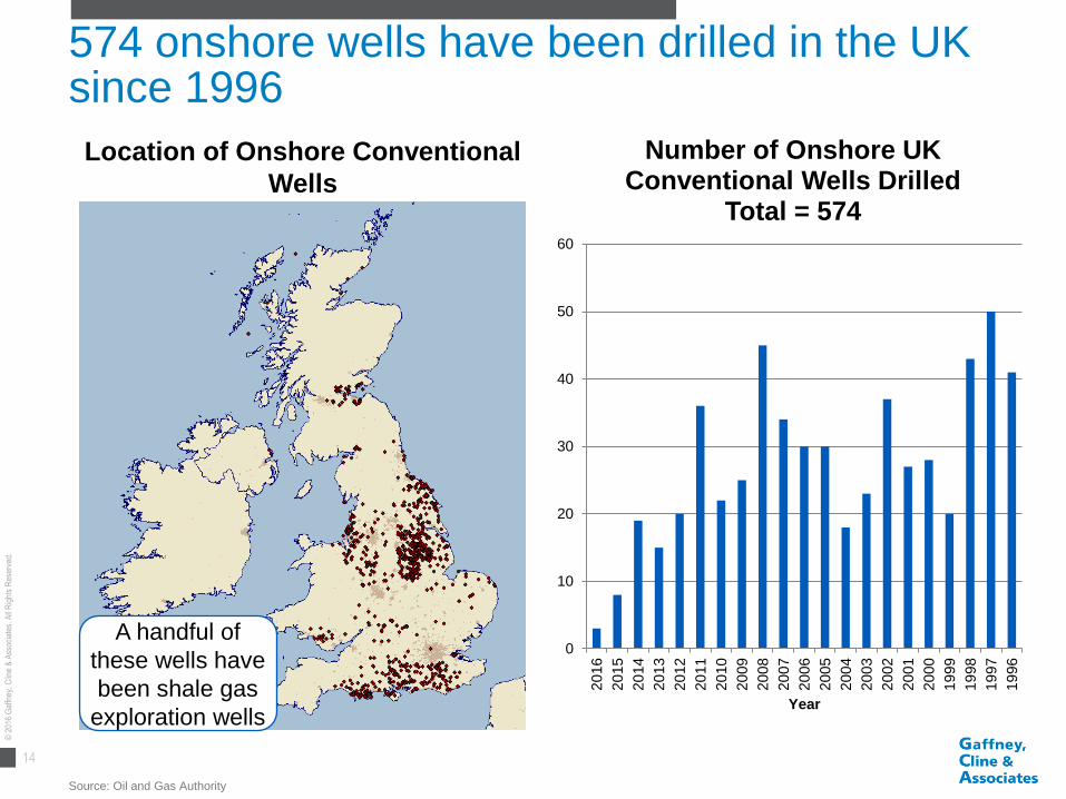
574 onshore wells have been drilled in the UK since 1996
Source: Oil and Gas Authority
0
10
20
30
40
50
60
20
16
20
15
20
14
20
13
20
12
20
11
20
10
20
09
20
08
20
07
20
06
20
05
20
04
20
03
20
02
20
01
20
00
19
99
19
98
19
97
19
96
Year
Number of Onshore UK Conventional Wells Drilled
Total = 574
Location of Onshore Conventional
Wells
A handful of
these wells have
been shale gas
exploration wells

15
© 2
016
Gaf
fney
, Clin
e &
Ass
ocia
tes.
All
Rig
hts
Res
erve
d.
Unconventional vs. Conventional
▪ Well completion design more complex
• Greater emphasis on geomechanics for produceability
• Water usage 10,000-30,000 m3 similar to other industrial activities
• Fracturing control processes defined
▪ First 2 phases likely to have considerably more traffic
• How much will depend on the volumes required for fracturing
• Intelligent scheduling & onsite storage can reduce significantly
▪ Last 2 phases will be identical
https://www.gov.uk/government/publications/about-shale-gas-and-hydraulic-fracturing-fracking/developing-shale-oil-and-gas-in-the-uk
16
© 2
016
Gaf
fney
, Clin
e &
Ass
ocia
tes.
All
Rig
hts
Res
erve
d.
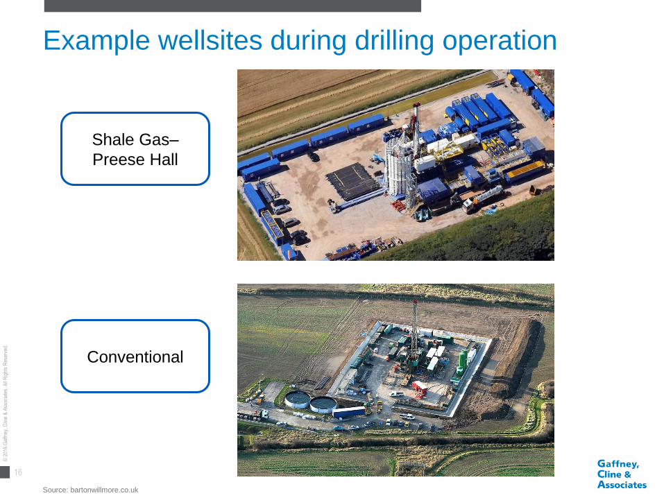
Example wellsites during drilling operation
Source: bartonwillmore.co.uk
Shale Gas–
Preese Hall
Conventional
17
© 2
016
Gaf
fney
, Clin
e &
Ass
ocia
tes.
All
Rig
hts
Res
erve
d.
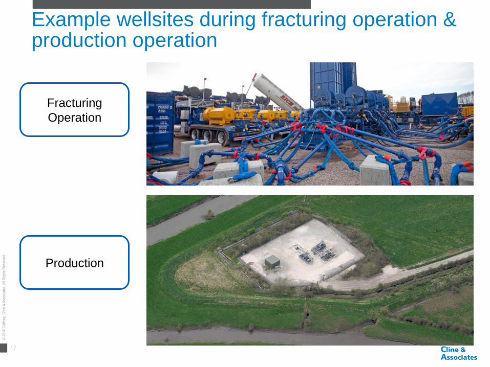
Example wellsites during fracturing operation & production operation
Fracturing
Operation
Production

18
© 2
016
Gaf
fney
, Clin
e &
Ass
ocia
tes.
All
Rig
hts
Res
erve
d.
Poole Harbour is home to an ‘onshore’ oilfield development in an environmental sensitive area

19
© 2
016
Gaf
fney
, Clin
e &
Ass
ocia
tes.
All
Rig
hts
Res
erve
d.
Canadian (onshore) shale play appraisal
Key:
Exploration
Appraisal
Development

20
© 2
016
Gaf
fney
, Clin
e &
Ass
ocia
tes.
All
Rig
hts
Res
erve
d.
Appraisal to development: scale shift
Source: Oil & Gas Authority, 14th onshore oil & gas licensing round

21
© 2
016
Gaf
fney
, Clin
e &
Ass
ocia
tes.
All
Rig
hts
Res
erve
d.
▪ Introduction to shale gas and oil
▪ Myths and reality
▪ Moving from conventional to unconventional in the UK
▪ UK regulations and risk management
▪ Key messages
Contents
22
© 2
016
Gaf
fney
, Clin
e &
Ass
ocia
tes.
All
Rig
hts
Res
erve
d.
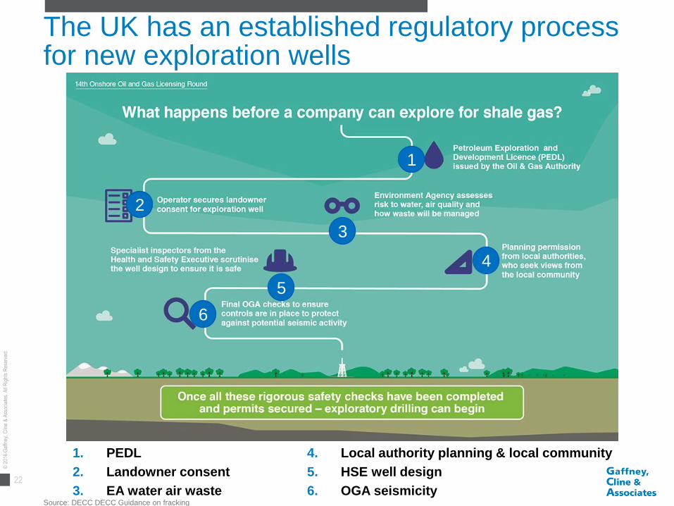
The UK has an established regulatory process for new exploration wells
Source: DECC DECC Guidance on fracking
1. PEDL
2. Landowner consent
3. EA water air waste
4. Local authority planning & local community
5. HSE well design
6. OGA seismicity
1
2
3
4
5
6

23
© 2
016
Gaf
fney
, Clin
e &
Ass
ocia
tes.
All
Rig
hts
Res
erve
d.
DECC has introduced a traffic light system to manage induced seismicity
https://www.gov.uk/government/uploads/system/uploads/attachment_data/file/270676/DECC_infographic_Traffic-light-system_finaldec13.pdf
• Baseline seismic monitoring to establish background seismicity in the area
of interest
• Characterisation of active faults using all available geological and
geophysical data
• Application of suitable ground motion prediction models to assess the
potential impact of any induced earthquakes
DECC Commissioned Report Recommended Control Measures
24
© 2
016
Gaf
fney
, Clin
e &
Ass
ocia
tes.
All
Rig
hts
Res
erve
d.
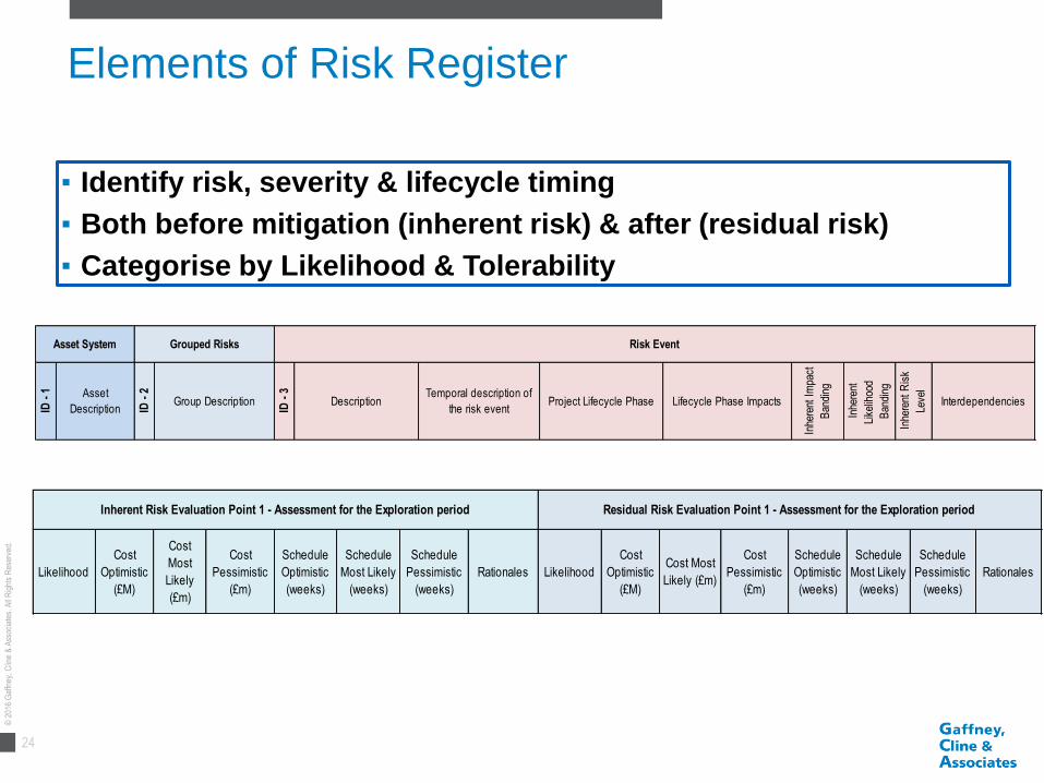
Elements of Risk Register
▪ Identify risk, severity & lifecycle timing
▪ Both before mitigation (inherent risk) & after (residual risk)
▪ Categorise by Likelihood & Tolerability
ID -
1 Asset
Description ID -
2
Group Description
ID -
3
DescriptionTemporal description of
the risk eventProject Lifecycle Phase Lifecycle Phase Impacts
Inhe
rent
Im
pact
Ban
ding
Inhe
rent
Like
lihoo
d
Ban
ding
Inhe
rent
Ris
k
Leve
l
Interdependencies
Asset System Grouped Risks Risk Event
Likelihood
Cost
Optimistic
(£M)
Cost
Most
Likely
(£m)
Cost
Pessimistic
(£m)
Schedule
Optimistic
(weeks)
Schedule
Most Likely
(weeks)
Schedule
Pessimistic
(weeks)
Rationales Likelihood
Cost
Optimistic
(£M)
Cost Most
Likely (£m)
Cost
Pessimistic
(£m)
Schedule
Optimistic
(weeks)
Schedule
Most Likely
(weeks)
Schedule
Pessimistic
(weeks)
Rationales
Residual Risk Evaluation Point 1 - Assessment for the Exploration periodInherent Risk Evaluation Point 1 - Assessment for the Exploration period
25
© 2
016
Gaf
fney
, Clin
e &
Ass
ocia
tes.
All
Rig
hts
Res
erve
d.
▪ Introduction to shale gas and oil
▪ Myths and reality
▪ Moving from conventional to unconventional in the UK
▪ UK regulations and risk management
▪ Key messages
Contents

26
© 2
016
Gaf
fney
, Clin
e &
Ass
ocia
tes.
All
Rig
hts
Res
erve
d.
Key messages
▪ Shale gas risk is not significantly different from conventionals
▪ Control measures particular to shale gas development
include:
– Induced seismicity monitoring
– Full disclosure of fracture fluid composition
▪ The challenge is communicating the science and engineering
to the public and planning authorities

27
© 2
016
Gaf
fney
, Clin
e &
Ass
ocia
tes.
All
Rig
hts
Res
erve
d.
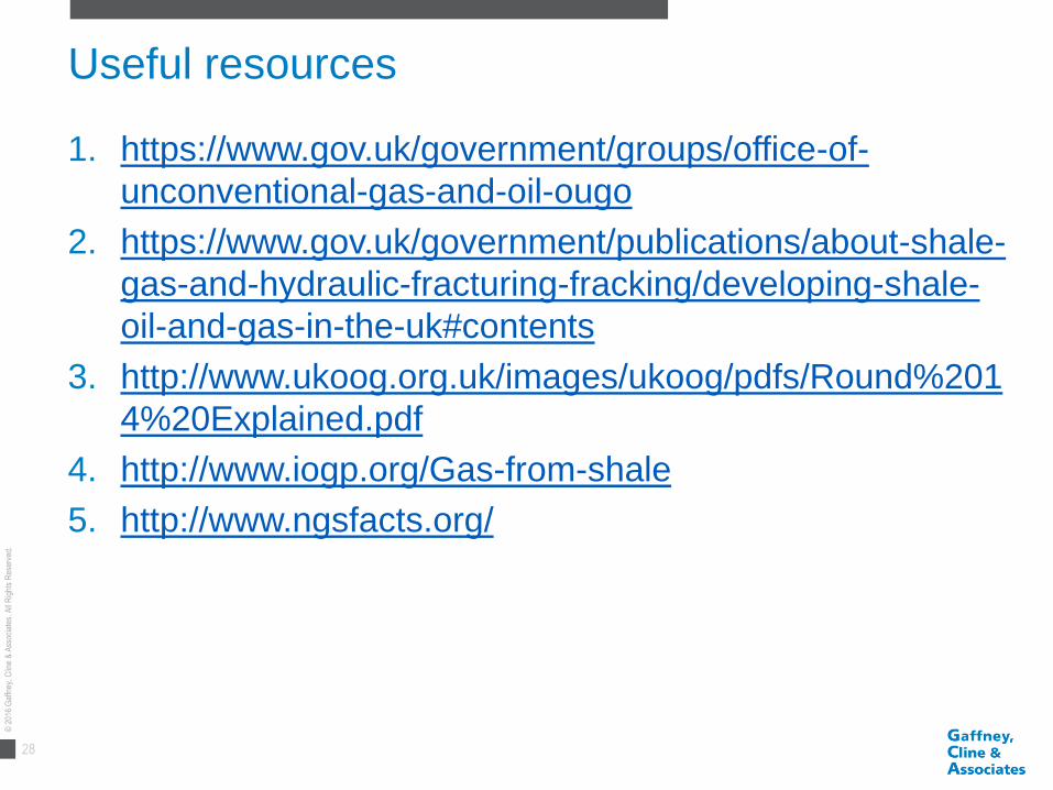
Useful resources
1. DECC Office of Unconventional Gas and Oil
2. DECC Guidance on fracking: developing shale oil and
gas in the UK
3. UKOOG 14th Onshore Licensing Round
4. IOGP Gas from shale
5. IOGP NGS Facts
28
© 2
016
Gaf
fney
, Clin
e &
Ass
ocia
tes.
All
Rig
hts
Res
erve
d.
Useful resources
1. https://www.gov.uk/government/groups/office-of-
unconventional-gas-and-oil-ougo
2. https://www.gov.uk/government/publications/about-shale-
gas-and-hydraulic-fracturing-fracking/developing-shale-
oil-and-gas-in-the-uk#contents
3. http://www.ukoog.org.uk/images/ukoog/pdfs/Round%201
4%20Explained.pdf
4. http://www.iogp.org/Gas-from-shale
5. http://www.ngsfacts.org/