shaking table tests at national laboratory for civil
TRANSCRIPT

Seismic Engineering Research Infrastructures for European Synergies
Investigation of seismic performance of multi-storey timber buildings within the framework of the SERIES Project
Shaking table tests at National Laboratory for Civil Engineering (Lisbon Portugal)
M. Piazza – University of Trento
A. Campos Costa – LNEC (Lisbon)
P. Candeias – LNEC (Lisbon)
1

SERIES Concluding Workshop Ispra 28-30 May 2013
Introduction - Constructive systems - Material and geometry - Tests setup - Accelerograms – Test 2
• Introduction
• Constructive systems
• Material and geometry
• Tests setup
• Accelerograms – test procedure
• Tests
• Preliminary results

SERIES Concluding Workshop Ispra 28-30 May 2013
Introduction - Constructive systems - Material and geometry - Tests setup - Accelerograms – Test 3
FACILITY: NESDE shake table, LNEC, Lisbon (PT)
TA AGREEMENT : January 2010 - Grant agreement n° 227887
STARTING DATE:
16th July 2011 kick-off meeting
END DATE:
21st February 2013
LEAD USER:
Maurizio Piazza & Roberto Tomasi, University of Trento (IT)
ADDITIONAL USERS:
Gerhard Schickhofer, TU Graz, AT Jorge Branco & Paulo B. Lourenço, University of Minho, PT
University of Trento Daniele Casagrande, Paolo Grossi, Maurizio Piazza, Tiziano Sartori, Roberto Tomasi
TU Graz Gerhard Schickhofer, Georg Flatscher
University of Minho Jorge Branco, Paulo B. Lourenço
LNEC Alfredo Campos Costa, Paulo Xavier Candeias
SERIES Concluding Workshop Ispra 28-30 May 2013
Introduction - Constructive systems - Material and geometry - Tests setup - Accelerograms – Test 4
The research on timber buildings involves University of Trento, Italy as the lead institution, University of Minho, Portugal, University of Graz, Austria.

SERIES Concluding Workshop Ispra 28-30 May 2013
Introduction - Constructive systems - Material and geometry - Tests setup - Accelerograms – Test
The goal of the research presented is the analysis of the seismic performance of timber buildings, with four kinds of timber housing system
5

SERIES Concluding Workshop Ispra 28-30 May 2013
Introduction - Constructive systems - Material and geometry - Tests setup - Accelerograms – Test
The goal of the research presented is the analysis of the seismic performance of timber buildings, with four kinds of timber housing system
6
University of Trento Light framed walls system

SERIES Concluding Workshop Ispra 28-30 May 2013
Introduction - Constructive systems - Material and geometry - Tests setup - Accelerograms – Test
The goal of the research presented is the analysis of the seismic performance of timber buildings, with four kinds of timber housing system
7
University of Trento Light framed walls system
University of Minho Log house system

SERIES Concluding Workshop Ispra 28-30 May 2013
Introduction - Constructive systems - Material and geometry - Tests setup - Accelerograms – Test
The goal of the research presented is the analysis of the seismic performance of timber buildings, with four kinds of timber housing system
8
University of Trento Light framed walls system
University of Minho Log house system
University of Graz CLT system

SERIES Concluding Workshop Ispra 28-30 May 2013
Introduction - Constructive systems - Material and geometry - Tests setup - Accelerograms – Test 9
Light timber framed wall construction (TF)
SERIES Concluding Workshop Ispra 28-30 May 2013
Introduction - Constructive systems - Material and geometry - Tests setup - Accelerograms – Test 10
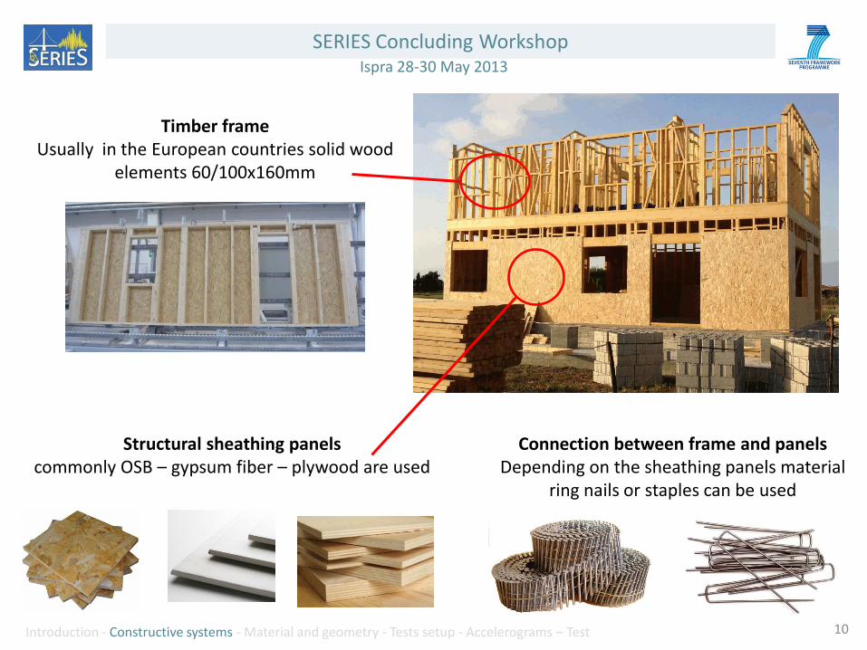
Timber frame Usually in the European countries solid wood
elements 60/100x160mm
Structural sheathing panels commonly OSB – gypsum fiber – plywood are used
Connection between frame and panels Depending on the sheathing panels material
ring nails or staples can be used

SERIES Concluding Workshop Ispra 28-30 May 2013
Introduction - Constructive systems - Material and geometry - Tests setup - Accelerograms – Test 11
Structural sheathing panels commonly OSB – gypsum fiber – plywood are used
Floors/roof Prefabricated box elements or classic
beam+boards/panels
SERIES Concluding Workshop Ispra 28-30 May 2013
Introduction - Constructive systems - Material and geometry - Tests setup - Accelerograms – Test 12
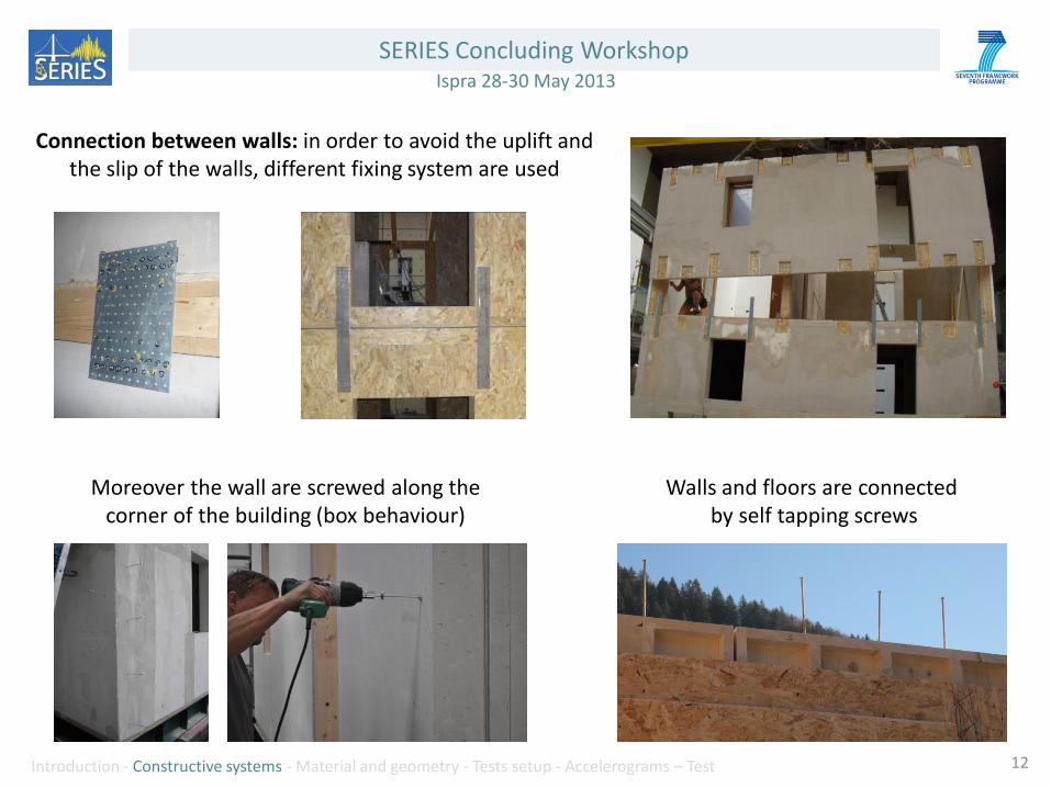
Connection between walls: in order to avoid the uplift and the slip of the walls, different fixing system are used
Moreover the wall are screwed along the corner of the building (box behaviour)
Walls and floors are connected by self tapping screws

SERIES Concluding Workshop Ispra 28-30 May 2013
Introduction - Constructive systems - Material and geometry - Tests setup - Accelerograms – Test 13
Connection between walls and foundation slab
Hold down
Angle bracket Alternative system
Tensile connection
Shear connection
SERIES Concluding Workshop Ispra 28-30 May 2013
Introduction - Constructive systems - Material and geometry - Tests setup - Accelerograms – Test 14
Log house construction (LH)

SERIES Concluding Workshop Ispra 28-30 May 2013
Introduction - Constructive systems - Material and geometry - Tests setup - Accelerograms – Test 15
Inner and outer walls are usually made of double/triple laminated beams placed one above the other
Different geometry of corner joint can be used

SERIES Concluding Workshop Ispra 28-30 May 2013
Introduction - Constructive systems - Material and geometry - Tests setup - Accelerograms – Test 16
Floors and roof are usually assembled with timber beams and panels
To avoid the problems related to the different degrees of wood shrinkage perpendicular to the grain, specific attention is required on the construction details
SERIES Concluding Workshop Ispra 28-30 May 2013
Introduction - Constructive systems - Material and geometry - Tests setup - Accelerograms – Test 17
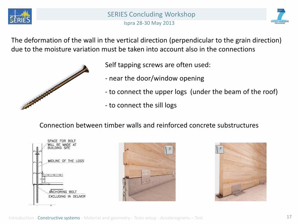
Connection between timber walls and reinforced concrete substructures
The deformation of the wall in the vertical direction (perpendicular to the grain direction) due to the moisture variation must be taken into account also in the connections
Self tapping screws are often used:
- near the door/window opening
- to connect the upper logs (under the beam of the roof)
- to connect the sill logs
SERIES Concluding Workshop Ispra 28-30 May 2013
Introduction - Constructive systems - Material and geometry - Tests setup - Accelerograms – Test 18
Cross Laminated Timber construction (CLT)
SERIES Concluding Workshop Ispra 28-30 May 2013
Introduction - Constructive systems - Material and geometry - Tests setup - Accelerograms – Test 19
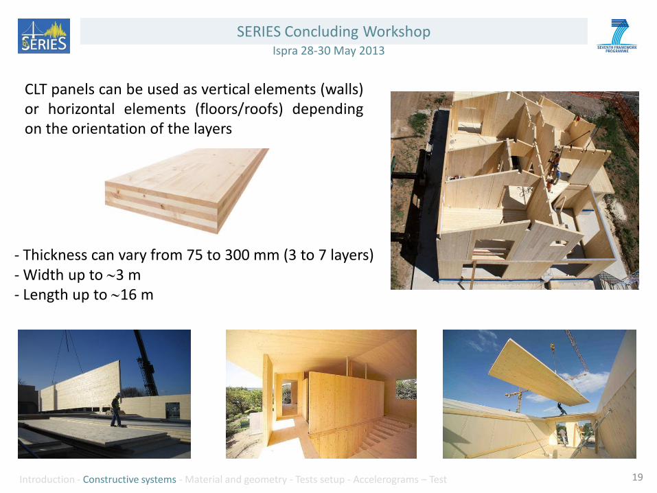
CLT panels can be used as vertical elements (walls) or horizontal elements (floors/roofs) depending on the orientation of the layers
- Thickness can vary from 75 to 300 mm (3 to 7 layers) - Width up to 3 m - Length up to 16 m

SERIES Concluding Workshop Ispra 28-30 May 2013
Introduction - Constructive systems - Material and geometry - Tests setup - Accelerograms – Test 20
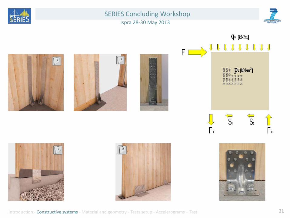
Connections
The connection between walls and floors are similar to the ones presented for the LTF
CLT Panel connection
SERIES Concluding Workshop Ispra 28-30 May 2013
Introduction - Constructive systems - Material and geometry - Tests setup - Accelerograms – Test 21
SERIES Concluding Workshop Ispra 28-30 May 2013
Introduction - Constructive systems - Material and geometry - Tests setup - Accelerograms – Test 22
Preliminary tests on the single component
SERIES Concluding Workshop Ispra 28-30 May 2013
Introduction - Constructive systems - Material and geometry - Tests setup - Accelerograms – Test 23
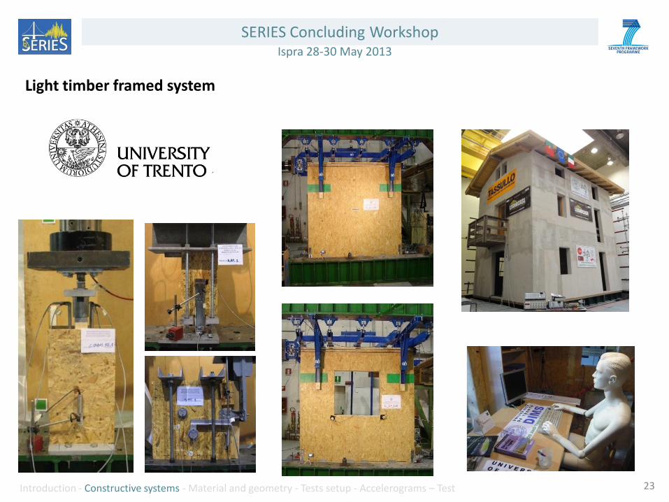
Light timber framed system

SERIES Concluding Workshop Ispra 28-30 May 2013
Introduction - Constructive systems - Material and geometry - Tests setup - Accelerograms – Test 24
Connections

SERIES Concluding Workshop Ispra 28-30 May 2013
Introduction - Constructive systems - Material and geometry - Tests setup - Accelerograms – Test 25
Real scale tests (Walls + connections)
SERIES Concluding Workshop Ispra 28-30 May 2013
Introduction - Constructive systems - Material and geometry - Tests setup - Accelerograms – Test 27
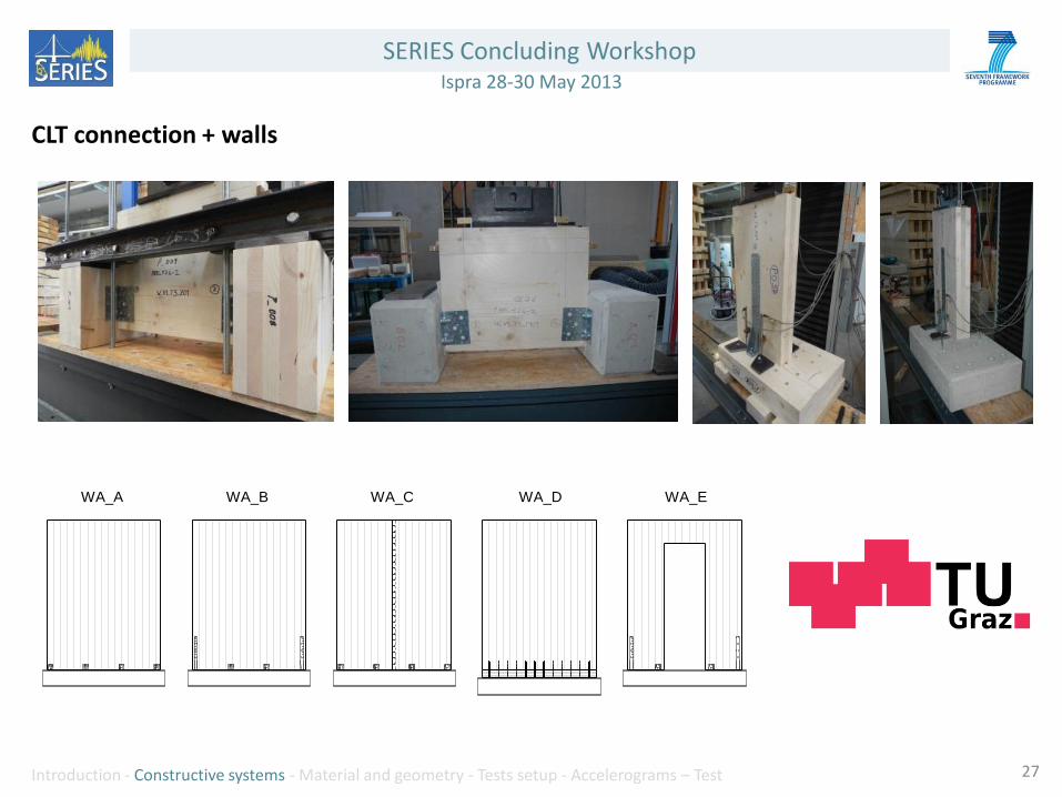
WA_A WA_B WA_C WA_D WA_E
CLT connection + walls

SERIES Concluding Workshop Ispra 28-30 May 2013
Introduction - Constructive systems - Material and geometry - Tests setup - Accelerograms – Test 28
Log house connection and walls

SERIES Concluding Workshop Ispra 28-30 May 2013
Introduction - Constructive systems - Material and geometry - Tests setup - Accelerograms – Test
Shaking Table Tests
29

SERIES Concluding Workshop Ispra 28-30 May 2013
Introduction - Constructive systems - Material and geometry - Tests setup - Accelerograms – Test
Specimens geometry
All specimens had the same geometry (squared 7 m x 5 m) and architectural layout.
• TF/CLT three storey to a maximum height to the peak of 7.65m
• LH two storey to a maximum height to the peak of 5.28m
All the four tested building were designed in accordance with EC 5/EC 8.
30

SERIES Concluding Workshop Ispra 28-30 May 2013
Introduction - Constructive systems - Material and geometry - Tests setup - Accelerograms – Test
In order to guarantee the comparison between the different systems, permanent loads and variable loads were the same (permanent: 1.3 kN/m2 - Variable load: 2 kN/m2)
31
Plan and the opening distribution were designed to reproduce a real single-family home.
SERIES Concluding Workshop Ispra 28-30 May 2013
Introduction - Constructive systems - Material and geometry - Tests setup - Accelerograms – Test
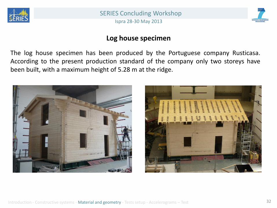
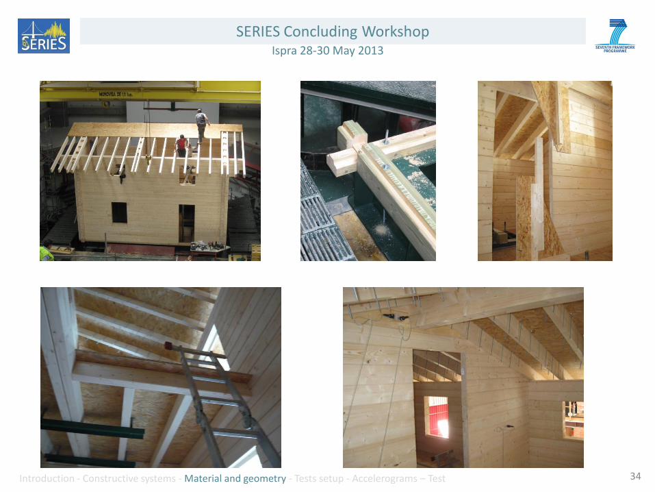
Log house specimen The log house specimen has been produced by the Portuguese company Rusticasa. According to the present production standard of the company only two storeys have been built, with a maximum height of 5.28 m at the ridge.
32

SERIES Concluding Workshop Ispra 28-30 May 2013
Introduction - Constructive systems - Material and geometry - Tests setup - Accelerograms – Test
Walls Inner walls logs 80x160 mm
Outer walls logs 160x160 mm
Floor
Timber beams 90 x 165 mm + 15 mm OSB sheathing panels, ring nails (2.8 x 60 mm)
Connection between walls and floors is obtained by means of dovetail joints
Roof Solid wood rafters (70 mm x 190 mm), over which OSB panels are nailed
The ridge board has a 120 mm x 200 mm cross-section
Connections The sill logs are connected to the steel plate through M16 bolts, class 8.8
33
SERIES Concluding Workshop Ispra 28-30 May 2013
Introduction - Constructive systems - Material and geometry - Tests setup - Accelerograms – Test 34

SERIES Concluding Workshop Ispra 28-30 May 2013
Introduction - Constructive systems - Material and geometry - Tests setup - Accelerograms – Test 35
Light timber framed wall specimen 1 Two different timber frame specimens were tested. The first one, with OSB structural sheathing panels, has been produced by the Italian company Legnocase. The structure was completed with external and internal claddings and one room of the 2nd storey was also equipped with laminate floor - drywall and ceilings – doors - windows and furnitures.

SERIES Concluding Workshop Ispra 28-30 May 2013
Introduction - Constructive systems - Material and geometry - Tests setup - Accelerograms – Test 36
Walls light frame walls (60/100x160 mm studs and 60 mm top/bottom beams)
OSB sheathing panels
Floor
600 mm x 140 mm modular Timber box elements (beams 78x31 mm upper and lower
boards 31 mm) + 15 mm OSB sheathing panels nailed with ring nails 2.8x60 mm)
Connection between walls and floors is obtained by means of screws
Roof Solid wood beams rafter 100x140 mm/760 mm, ridge beam 160x240 mm, purlins
160x160 mm. Wooden plank (20 mm) reinforced with perforated metal strips
Connections
Shear connections: steel plate (anker nails 4x60 mm)
Uplift connections: tie-downs (anker nails 4x60 mm)
Base shear connections: screws 8x180 mm
Base uplift connections: hold-downs (anker nails 4x60 mm)

SERIES Concluding Workshop Ispra 28-30 May 2013
Introduction - Constructive systems - Material and geometry - Tests setup - Accelerograms – Test 37

SERIES Concluding Workshop Ispra 28-30 May 2013
Introduction - Constructive systems - Material and geometry - Tests setup - Accelerograms – Test 38
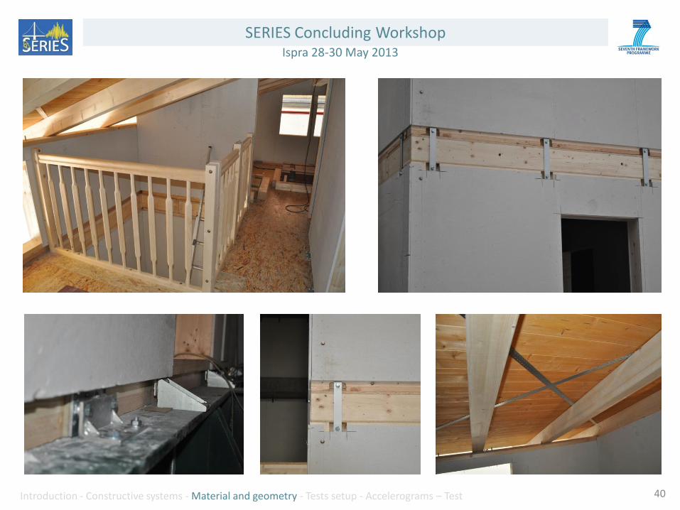
Light timber framed wall specimen 2 The second TFS building, produced by Italian company Rubner_haus, was built with gypsum fibre structural sheathing panels connected to the timber frame of the walls by means of steel staples (instead of using the system OSB + ring nails)

SERIES Concluding Workshop Ispra 28-30 May 2013
Introduction - Constructive systems - Material and geometry - Tests setup - Accelerograms – Test 39
Walls light frame walls (80x120/160 mm studs and 60 mm top/bottom beams)
Gypsum fiber sheathing panels
Floor
Timber beams 80x200 mm + 12 mm OSB lower panels and 22 mm OSB upper panels
(all panels nailed with ring nails 2.8x60 mm)
Connection between walls and floors is obtained by means of screws
Roof Solid wood beams rafter 120x160 mm/840 mm , ridge beam 160x240 mm, purlins
160x240mm. Wood planks (20 mm) reinforced with perforated metal strips
Connections
Base shear connections: angle brackets (anker nails 4x60 mm)
Base uplift connections: hold-downs (anker nails 4x60 mm)
Shear connections: angle brackets (anker nails 4x60 mm)
Uplift connections: tie-downs (anker nails 4x60 mm)
SERIES Concluding Workshop Ispra 28-30 May 2013
Introduction - Constructive systems - Material and geometry - Tests setup - Accelerograms – Test 40

SERIES Concluding Workshop Ispra 28-30 May 2013
Introduction - Constructive systems - Material and geometry - Tests setup - Accelerograms – Test 41
Cross laminated timber specimen The last test of Timber Building project within SERIES was carried out on CLT three storey building. In this case all the elements (walls, floors, roof) were built with cross laminated timber panels of different thickness.

SERIES Concluding Workshop Ispra 28-30 May 2013
Introduction - Constructive systems - Material and geometry - Tests setup - Accelerograms – Test 42
Walls 3 layers CLT wall panel 100 mm (layup 30-40-30)
Floor
5 layers CLT floor panel 150mm (layup 30-30-30-30-30). Connection between walls
and floors is obtained by means of screws
Roof 3 layers CLT floor panel 99mm (layup 33-33-33). Connection between walls and roof
panels is obtained by means of screws
Connections
Base shear connections: angle brackets (anker nails 4x60 mm)
Base uplift connections: hold-downs (anker nails 4x60 mm)
Shear connections: angle brackets (anker nails 4x60 mm)
Uplift connections: hold-downs (anker nails 4x60 mm)
SERIES Concluding Workshop Ispra 28-30 May 2013
Introduction - Constructive systems - Material and geometry - Tests setup - Accelerograms – Test 43

SERIES Concluding Workshop Ispra 28-30 May 2013
Introduction - Constructive systems - Material and geometry - Tests setup - Accelerograms – Test 44
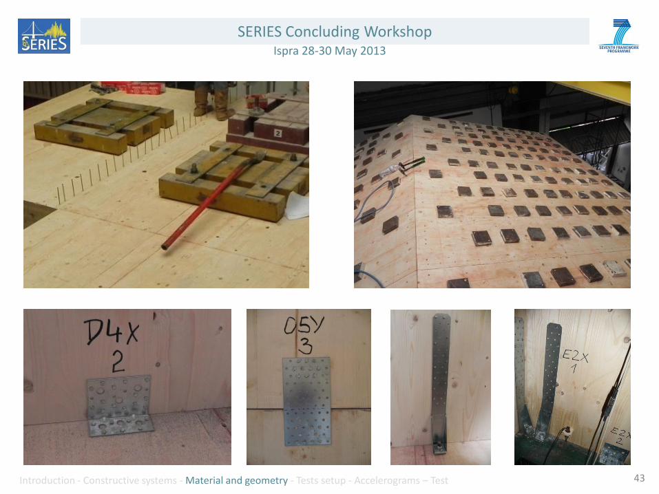
To test real scale lightweight timber structures the size of the table (5.6x4.6 m) was
enlarged with a structural base frame (5x7m) made of steel beams bolted on the top plate.
Steel plates, anchored to the floor, reproduces the weight
according the load combination for seismic load cases
(self-weight of flooring and a fraction of variable load ).
SERIES Concluding Workshop Ispra 28-30 May 2013
Introduction - Constructive systems - Material and geometry - Tests setup - Accelerograms – Test 45
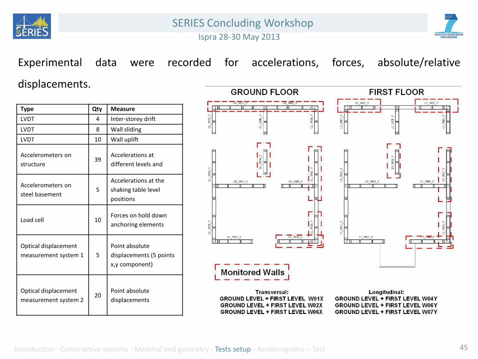
Experimental data were recorded for accelerations, forces, absolute/relative
displacements.
Type Qty Measure
LVDT 4 Inter-storey drift
LVDT 8 Wall sliding
LVDT 10 Wall uplift
Accelerometers on
structure 39
Accelerations at
different levels and
Accelerometers on
steel basement 5
Accelerations at the
shaking table level
positions
Load cell 10 Forces on hold down
anchoring elements
Optical displacement
measurement system 1
5
Point absolute
displacements (5 points
x,y component)
Optical displacement
measurement system 2 20
Point absolute
displacements

SERIES Concluding Workshop Ispra 28-30 May 2013
Introduction - Constructive systems - Material and geometry - Tests setup - Accelerograms – Test 46
LVDT displacement transducers
Accelerometers

SERIES Concluding Workshop Ispra 28-30 May 2013
Introduction - Constructive systems - Material and geometry - Tests setup - Accelerograms – Test 47
Load Cell LNEC optical displacement measurement system
SERIES Concluding Workshop Ispra 28-30 May 2013
Introduction - Constructive systems - Material and geometry - Tests setup - Accelerograms – Test
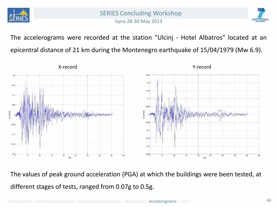
The accelerograms were recorded at the station "Ulcinj - Hotel Albatros" located at an
epicentral distance of 21 km during the Montenegro earthquake of 15/04/1979 (Mw 6.9).
The values of peak ground acceleration (PGA) at which the buildings were been tested, at
different stages of tests, ranged from 0.07g to 0.5g.
X-record Y-record
48

SERIES Concluding Workshop Ispra 28-30 May 2013
Introduction - Constructive systems - Material and geometry - Tests setup - Accelerograms – Test 49
0.2
2
20
200
0.04 0.4 4 Spe
ctra
l ve
loci
ty [
cm/s
]
Period [s]
Trans.
Ref.
0.2
2
20
200
0.04 0.4 4 Spe
ctra
l ve
loci
ty [
cm/s
]
Period [s]
Long.
Ref.
0.2
2
20
200
0.04 0.4 4 Spe
ctra
l ve
loci
ty [
cm/s
]
Period [s]
Trans.
Ref.
Rusticasa building
0.28g
0.07g
0.2
2
20
200
0.04 0.4 4 Spe
ctra
l ve
loci
ty [
cm/s
]
Period [s]
Long.
Ref.
0.2
2
20
200
0.04 0.4 4 Spe
ctra
l ve
loci
ty [
cm/s
]
Period [s]
Trans.
Ref.
0.2
2
20
200
0.04 0.4 4 Spe
ctra
l ve
loci
ty [
cm/s
]
Period [s]
Long.
Ref.
0.50g
0.15g
This stage was skipped.

SERIES Concluding Workshop Ispra 28-30 May 2013
Introduction - Constructive systems - Material and geometry - Tests setup - Accelerograms – Test 50
0.2
2
20
200
0.04 0.4 4 Spe
ctra
l ve
loci
ty [
cm/s
]
Period [s]
Trans.
Ref.
0.2
2
20
200
0.04 0.4 4 Spe
ctra
l ve
loci
ty [
cm/s
]
Period [s]
Long.
Ref.
Legnocase building
0.28g
0.07g
0.50g
0.2
2
20
200
0.04 0.4 4 Spe
ctra
l ve
loci
ty [
cm/s
]
Period [s]
Trans.
Ref.
0.15g
0.2
2
20
200
0.04 0.4 4 Spe
ctra
l ve
loci
ty [
cm/s
]
Period [s]
Long.
Ref.
0.2
2
20
200
0.04 0.4 4 Spe
ctra
l ve
loci
ty [
cm/s
]
Period [s]
Trans.
Ref.
0.2
2
20
200
0.04 0.4 4 Spe
ctra
l ve
loci
ty [
cm/s
]
Period [s]
Long.
Ref.
0.2
2
20
200
0.04 0.4 4 Spe
ctra
l ve
loci
ty [
cm/s
]
Period [s]
Trans.
Ref.
0.2
2
20
200
0.04 0.4 4 Spe
ctra
l ve
loci
ty [
cm/s
]
Period [s]
Long.
Ref.

SERIES Concluding Workshop Ispra 28-30 May 2013
Introduction - Constructive systems - Material and geometry - Tests setup - Accelerograms – Test 51
Rubnerhaus building
0.28g
0.07g
0.50g
0.15g
0.2
2
20
200
0.04 0.4 4 Spe
ctra
l ve
loci
ty [
cm/s
]
Period [s]
Trans.
Ref.
0.2
2
20
200
0.04 0.4 4 Spe
ctra
l ve
loci
ty [
cm/s
]
Period [s]
Long.
Ref.
0.2
2
20
200
0.04 0.4 4 Spe
ctra
l ve
loci
ty [
cm/s
]
Period [s]
Trans.
Ref.
0.2
2
20
200
0.04 0.4 4 Spe
ctra
l ve
loci
ty [
cm/s
]
Period [s]
Long.
Ref.
0.2
2
20
200
0.04 0.4 4 Spe
ctra
l ve
loci
ty [
cm/s
]
Period [s]
Trans.
Ref.
0.2
2
20
200
0.04 0.4 4 Spe
ctra
l ve
loci
ty [
cm/s
]
Period [s]
Long.
Ref.
0.2
2
20
200
0.04 0.4 4 Spe
ctra
l ve
loci
ty [
cm/s
]
Period [s]
Trans.
Ref.
0.2
2
20
200
0.04 0.4 4 Spe
ctra
l ve
loci
ty [
cm/s
]
Period [s]
Long.
Ref.
SERIES Concluding Workshop Ispra 28-30 May 2013
Introduction - Constructive systems - Material and geometry - Tests setup - Accelerograms – Test 52
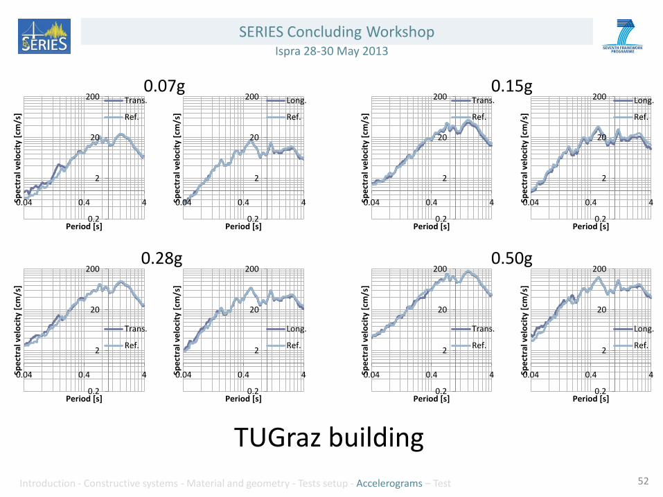
TUGraz building
0.28g
0.07g
0.50g
0.15g
0.2
2
20
200
0.04 0.4 4 Spe
ctra
l ve
loci
ty [
cm/s
]
Period [s]
Trans.
Ref.
0.2
2
20
200
0.04 0.4 4 Spe
ctra
l ve
loci
ty [
cm/s
]
Period [s]
Long.
Ref.
0.2
2
20
200
0.04 0.4 4 Spe
ctra
l ve
loci
ty [
cm/s
]
Period [s]
Trans.
Ref.
0.2
2
20
200
0.04 0.4 4 Spe
ctra
l ve
loci
ty [
cm/s
]
Period [s]
Long.
Ref.
0.2
2
20
200
0.04 0.4 4 Spe
ctra
l ve
loci
ty [
cm/s
]
Period [s]
Trans.
Ref.
0.2
2
20
200
0.04 0.4 4 Spe
ctra
l ve
loci
ty [
cm/s
]
Period [s]
Long.
Ref.
0.2
2
20
200
0.04 0.4 4 Spe
ctra
l ve
loci
ty [
cm/s
]
Period [s]
Trans.
Ref.
0.2
2
20
200
0.04 0.4 4 Spe
ctra
l ve
loci
ty [
cm/s
]
Period [s]
Long.
Ref.
SERIES Concluding Workshop Ispra 28-30 May 2013
Introduction - Constructive systems - Material and geometry - Tests setup - Accelerograms - Test 53
Preliminary results

SERIES Concluding Workshop Ispra 28-30 May 2013
Introduction - Constructive systems - Material and geometry - Tests setup - Accelerograms - Test 54
Legnocase building
Sensor locations
MODE_i_j MODE_01_00 MODE_02_00 MODE_03_00 MODE_04_00 MODE_05_00 MODE_06_00
Frequency [Hz] 3.62 4.25 6.03 8.22 15.88 20.56
MODE_01_00 3.62 1.0000 0.3747 0.1033 0.1918 0.0014 0.1988
MODE_02_00 4.25 0.3747 1.0000 0.0283 0.1166 0.0191 0.0332
MODE_03_00 6.03 0.1033 0.0283 1.0000 0.1330 0.0032 0.0327
MODE_04_00 8.22 0.1918 0.1166 0.1330 1.0000 0.5394 0.0117
MODE_05_00 15.88 0.0014 0.0191 0.0032 0.5394 1.0000 0.0050
MODE_06_00 20.56 0.1988 0.0332 0.0327 0.0117 0.0050 1.0000
i Mode
j dynamic identification
Initial frequencies
Initial MAC coefficients

SERIES Concluding Workshop Ispra 28-30 May 2013
Introduction - Constructive systems - Material and geometry - Tests setup - Accelerograms - Test 55
Mode 1: f= 3.62 Hz Mode 2: f= 4.25 Hz Mode 3: f= 6.03 Hz
Initial frequencies and mode shapes
Final frequencies and mode shapes Mode 1: f= 3.35 Hz Mode 2: f= 3.85 Hz Mode 3: f= 5.84 Hz

SERIES Concluding Workshop Ispra 28-30 May 2013
Introduction - Constructive systems - Material and geometry - Tests setup - Accelerograms - Test 56
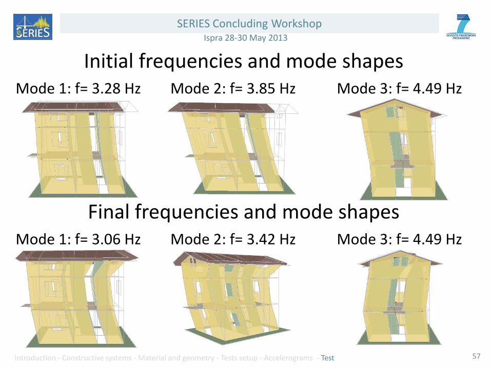
Rubnerhaus building
Sensor locations
Initial frequencies
Initial MAC coefficients MODE_i_j MODE_01_00 MODE_02_00 MODE_03_00 MODE_04_00 MODE_05_00 MODE_06_00
Frequency [Hz] 3.28 3.85 4.49 5.92 14.32 18.46
MODE_01_00 3.28 1.0000 0.3106 0.0785 0.0154 0.0010 0.1023
MODE_02_00 3.85 0.3106 1.0000 0.0697 0.0173 0.0032 0.0045
MODE_03_00 4.49 0.0785 0.0697 1.0000 0.1180 0.5586 0.1319
MODE_04_00 5.92 0.0154 0.0173 0.1180 1.0000 0.1380 0.0339
MODE_05_00 14.32 0.0010 0.0032 0.5586 0.1380 1.0000 0.1894
MODE_06_00 18.46 0.1023 0.0045 0.1319 0.0339 0.1894 1.0000
i Mode
j dynamic identification
SERIES Concluding Workshop Ispra 28-30 May 2013
Introduction - Constructive systems - Material and geometry - Tests setup - Accelerograms - Test 57
Mode 1: f= 3.28 Hz Mode 2: f= 3.85 Hz Mode 3: f= 4.49 Hz
Initial frequencies and mode shapes
Final frequencies and mode shapes Mode 1: f= 3.06 Hz Mode 2: f= 3.42 Hz Mode 3: f= 4.49 Hz

SERIES Concluding Workshop Ispra 28-30 May 2013
Introduction - Constructive systems - Material and geometry - Tests setup - Accelerograms - Test 58
TUGraz building
Sensor locations
Initial frequencies
Initial MAC coefficients MODE_i_j MODE_01_01 MODE_02_01 MODE_03_01 MODE_04_01 MODE_05_01 MODE_06_01 MODE_07_01 MODE_08_01
Frequency [Hz] 3.98 5.34 6.59 14.55 15.46 19.78 21.26 23.42
MODE_01_01 3.98 1.0000 0.0014 0.0026 0.0286 0.0428 0.0331 0.0236 0.0013
MODE_02_01 5.34 0.0014 1.0000 0.1340 0.0546 0.0010 0.0008 0.1425 0.0015
MODE_03_01 6.59 0.0026 0.1340 1.0000 0.0299 0.1405 0.0498 0.0003 0.0062
MODE_04_01 14.55 0.0286 0.0546 0.0299 1.0000 0.0307 0.0134 0.0351 0.0934
MODE_05_01 15.46 0.0428 0.0010 0.1405 0.0307 1.0000 0.0006 0.2432 0.0732
MODE_06_01 19.78 0.0331 0.0008 0.0498 0.0134 0.0006 1.0000 0.2799 0.0359
MODE_07_01 21.26 0.0236 0.1425 0.0003 0.0351 0.2432 0.2799 1.0000 0.1014
MODE_08_01 23.42 0.0013 0.0015 0.0062 0.0934 0.0732 0.0359 0.1014 1.0000
i Mode
j dynamic identification

SERIES Concluding Workshop Ispra 28-30 May 2013
Introduction - Constructive systems - Material and geometry - Tests setup - Accelerograms - Test 59
Mode 1: f= 3.98 Hz Mode 2: f= 5.34 Hz Mode 3: f= 6.59 Hz
Initial frequencies and mode shapes
Final frequencies and mode shapes Mode 1: f= 3.75 Hz Mode 2: f= 5.23 Hz Mode 3: f= 6.25 Hz

SERIES Concluding Workshop Ispra 28-30 May 2013
Introduction - Constructive systems - Material and geometry - Tests setup - Accelerograms - Test
After each stage of testing a dynamic identification of the shaking table and of the model
was performed, in order to quantify the damage of the building after each seismic test.
Evaluation of the damage was also done after each test through a careful visual inspection.
60

SERIES Concluding Workshop Ispra 28-30 May 2013
Introduction - Constructive systems - Material and geometry - Tests setup - Accelerograms - Test 61

SERIES Concluding Workshop Ispra 28-30 May 2013
Introduction - Constructive systems - Material and geometry - Tests setup - Accelerograms - Test 62
Possible failure mechanisms of the connections between elements for TF and CLT systems
Sliding mechanisms

SERIES Concluding Workshop Ispra 28-30 May 2013
Introduction - Constructive systems - Material and geometry - Tests setup - Accelerograms - Test 63
Overturning/rocking mechanisms
SERIES Concluding Workshop Ispra 28-30 May 2013
Introduction - Constructive systems - Material and geometry - Tests setup - Accelerograms - Test 64
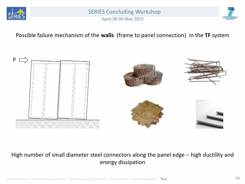
Possible failure mechanism of the walls (frame to panel connection) in the TF system
High number of small diameter steel connectors along the panel edge – high ductility and energy dissipation

SERIES Concluding Workshop Ispra 28-30 May 2013
Introduction - Constructive systems - Material and geometry - Tests setup - Accelerograms - Test 65
The failure mechanism of the LH walls, is due to the failure of the corner joint. The structural behavior is strongly influenced by friction between the logs (pre-sliding phase)

SERIES Concluding Workshop Ispra 28-30 May 2013
Introduction - Constructive systems - Material and geometry - Tests setup - Accelerograms - Test 66

SERIES Concluding Workshop Ispra 28-30 May 2013
Introduction - Constructive systems - Material and geometry - Tests setup - Accelerograms – Test 67
THANKS FOR THE KIND ATTENTION!