shaft wall - knauf australia
TRANSCRIPT

209
Shaft WallShaft Wall systems are fire rated non-load bearing walls used for shafts and service ducts.
Shaft Wall systems are ideal when constructing a wall where access is only possible from one side. This side is referred to as the storey side. Shaft Wall has advantages compared with masonry construction:
75% lighter Thinner – typically less than 100mm wide using 64mm
CH-Studs No wet trades required Faster installation – no scaffolding is required inside the
shaft.
SYSTEMS 210
INSTALLATION 211
GENERAL REQUIREMENTS 211
FRAMING 212
PLASTERBOARD LAYOUT 213
PLASTERBOARD FIXING 214
CONSTRUCTION DETAILS 217

Technical Advice 1300 724 505 knaufmetal.com.au210
SHAFT WALLFire RatedSystems
3.3.1
Technical Advice 1300 724 505 knaufmetal.com.au210
3.3.1Systems
KSHW1WALL LINING: [Side 1] 1 layer of 16mm FireShield [Side 2] 1 layer of 25mm ShaftLiner encased in CH-studsFRAME: Shaft Wall CH-steel studs at maximum 600mm centres[16mm FireShield can be substituted with 16mm TruRock]
FRL – /60/60
rated from both sidesFire Report FAR 2863
CH-Stud Size (mm)
Max Height (m)
Width(mm)
Sound Insulation for studs at 600mm centres and thinnest BMT Rw (Rw + Ctr)
CH-Stud Depth CH-Stud BMTNon-Load Bearing Studs at 600mm
UDL 0.25kPa
Non-Load Bearing Studs at 600mm
UDL 0.35kPaNo Insulation
50mm EarthWool 11 kg/m³
60mm Polyester
ASB3Acoustic Report
Day Design 3094-18640.55 2.95 2.64
80 39 (32) 46 (39) 46 (38)0.9 3.46 3.09
1020.55 3.73 2.66
118 42 (33) 48 (41) 48 (41)0.9 4.98 4.19
KSHW2WALL LINING: [Side 1] 2 layers of 16mm FireShield
[Side 2] 1 layer of 25mm ShaftLiner encased in CH-studsFRAME: Shaft Wall CH-steel studs at maximum 600mm centres[16mm FireShield can be substituted with 16mm TruRock]
FRL – /120/120
rated from both sidesFire Report FAR 2863
CH-Stud Size (mm)
Max Height (m)
Width(mm)
Sound Insulation for studs at 600mm centres and thinnest BMT Rw (Rw + Ctr)
CH-Stud Depth CH-Stud BMTNon-Load Bearing Studs at 600mm
UDL 0.25kPa
Non-Load Bearing Studs at 600mm
UDL 0.35kPaNo Insulation
50mm EarthWool 11 kg/m³
60mm Polyester
ASB3Acoustic Report
Day Design 3094-18640.55 3.73 2.66
96 44 (36) 50 (42) 50 (42)0.9 4.38 3.89
1020.55 3.73 2.66
134 46 (37) 52 (46) 52 (46)0.9 5.51 4.19
KSHW3WALL LINING: [Side 1] 1 layer of 16mm FireShield
[Side 2] 1 layer of 25mm ShaftLiner encased in CH-studs and 1 layer of 16mm FireShieldFRAME: Shaft Wall CH-steel studs at maximum 600mm centres[16mm FireShield can be substituted with 16mm TruRock]
FRL – /120/120
rated from both sidesFire Report FAR 2863
CH-Stud Size (mm)
Max Height (m)
Width(mm)
Sound Insulation for studs at 600mm centres and thinnest BMT Rw (Rw + Ctr)
CH-Stud Depth CH-Stud BMTNon-Load Bearing Studs at 600mm
UDL 0.25kPa
Non-Load Bearing Studs at 600mm
UDL 0.35kPaNo Insulation
50mm EarthWool 11 kg/m³
60mm Polyester
ASB3Acoustic Report
Day Design 3094-18640.55 3.73 2.66
96 42 (35) 50 (42) 50 (42)0.9 4.38 3.89
1020.55 3.73 2.66
134 45 (36) 52 (45) 52 (45)0.9 5.51 4.19

Technical Advice 1300 724 505 knaufplasterboard.com.au 211
SHAFT WALLGeneral Requirements Installation
3.3.1
General Requirements
Fire Rated
Install control joints in plasterboard walls: At 12m maximum intervals At all control joints in the structure At any change in the substrate material.
Only joint the face layer. As a minimum to achieve the FRL, only use paper tape and: Two coats of MastaBase/MastaLongset, or Three coats of MastaLite.
Use approved fire rated penetration details. Fire penetrations may require fire collars or other devices to maintain fire performance.
Use fire sealant on all gaps and around perimeter, vermiculite plaster is not permitted.
For acceptable modifications or variations to fire rated systems. [Refer to Section 2.3
Fire Resistance]

64 or 102mm
64 or 102mm
64 or 102mm
64 or 102mm
50mm
25mm
57mm75mm
25mm 25mm
38mm 19mm
35mm 25mm
E-Stud 0.55mm BMT(Rondo No.574 or No.594)
Bottom J-track and End Stud J-track0.8mm BMT (Rondo No.578 or No.598)
Deflection Head J-track and Jamb Stud0.8mm BMT (Rondo No.579 or No.599)
CH-Stud0.55mm BMT and 0.9mm BMT(Rondo No.570 or No.590)
FIGURE 1 Shaft Wall CH-StudSection
FIGURE 2 Shaft Wall E-StudSection
FIGURE 3 Shaft Wall J-TrackSection
FIGURE 4 Shaft Wall Deflection Head J-TrackSection
Framing
Fire Rated
Fix the bottom track and top track or deflection head at 600mm maximum centres and 100mm maximum from each end.
Use a deflection head if: Wall heights are 4800mm or greater Ceiling, roof or floor movement is expected.
Space CH-Studs at 600mm centres maximum.
Push CH-Studs down completely into bottom track.
Friction fit all CH-Studs. They must not be screwed to the top and bottom tracks.
Plumbing and electrical services must not protrude beyond the face of the stud.
Technical Advice 1300 724 505 knaufmetal.com.au212
SHAFT WALLFraming Installation
3.3.1

End stud J-track
CH-stud
Bottom J-track
E-stud
25mm ShaftLiner
Fold flange of J-track 60mm to install last ShaftLiner
Deflection head J-track/ top J-track
Use CH-stud horizontally along butt joint in ShaftLiner
Stagger butt joints in ShaftLiner to upper and lower third of wall. Stagger butt joints between adjoining sheets
2
1
345
67
89
1110
FIGURE 5 Shaft Wall Construction SequencePerspective
FIGURE 6 ShaftLiner Butt Joint LayoutPerspective
Technical Advice 1300 724 505 knaufplasterboard.com.au 213
SHAFT WALLPlasterboard Layout Installation
3.3.1
Plasterboard Layout

Technical Advice 1300 724 505 knaufmetal.com.au214
SHAFT WALLPlasterboard Layout and Fixing Installation
3.3.1
Fire Rated
FireShield Horizontal Layout
Stagger butt joints by 600mm minimum on adjoining sheets and between layers.
Stagger recessed edges by 300mm minimum between layers.
First layer butt joints must be backed by a CH-stud.
FireShield Vertical Layout
Stagger butt joints by 600mm minimum on adjoining sheets and between layers.
Stagger recessed edges by 300mm minimum between layers.
First layer butt joints must be backed by a nogging.
ShaftLiner Layout
If the wall height exceeds the length of ShaftLiner, position the ShaftLiner butt joints within the upper and lower third of the wall. [Refer to Figure 6]
Stagger ShaftLiner butt joints for adjacent panels and reinforce with horizontal CH-stud cut to fit between the vertical studs. [Refer to Figure 6]
Install FireShield horizontally when practical to reduce the effect of glancing light.
Minimise butt joints by using long sheets.
Plasterboard FixingFire
Rated
Use the ‘Screw Only Method’. Stud adhesive is not permitted.
Drive screws to just below the sheet surface, taking care not to break the paper linerboard.
Laminating screws can be used to fix butt joints in the second layer.
SCREW TYPE AND MINIMUM SIZE FOR THE INSTALLATION OF PLASTERBOARD TO STEEL
Plasterboard Thickness 1st Layer 2nd Layer 3rd Layer
16mm FireShield 30mm screw 45mm screw* 65mm screw*
25mm ShaftLiner 45mm screw+ – –
For steel ≤ 0.75mm BMT minimum 6g fine thread needle point screws. For steel ≥ 0.75mm BMT minimum 6g fine thread drill point screws. *38mm – 10g Laminating screws may be used as detailed in installation diagrams. + Use for securing ShaftLiner to J-track when the J-track is being used as an end stud.
Plasterboard Layout

Jointing Only joint the face layer. As a minimum, use paper tape with either two coats of MastaBase/MastaLongset or three coats of MastaLite. Alternatively use Knauf Bindex Fire and Acoustic Sealant according to the Tech Data Sheet.
FIGURE 8 Fire Rated 2 Layers - Horizontal + HorizontalScrew Only Method
Fix on each stud 50mm
Corners2nd layer300mm max
Fix on each stud 60 - 100mm
Sealant Use Knauf Bindex Fire and Acoustic Sealant on all gaps and around perimeter to maintain fire and acoustic integrity
Plasterboard must not be fixed to head trackRecessed Edges Fix 1st and
2nd layer recessed edges on each stud. Stagger recessed edges by
300mm min between layers.
Field 1st layer 600mm max
Corners1st layer 600mm
max1st layer 600mm max
Field 2nd layer 300mm max
Stagger recessed edges by 300mm min between layers
2nd layer 300mm max
Openings1st layer 600mm max vertical screw spacing
Butt Joints1st layer butt joints
must be fixed at 600mm max
centres and backed by a stud, or
alternatively back with 51mm min
track
Sheet EdgesFix screws
10 - 50mm from sheet edges
except at head and base tracks
Stagger butt joints by 300mm min between layers
Butt Joints 2nd layer. Fix on a stud at 200mm max centres. Alternatively, float butt joints and laminate to 1st layer using laminating screws at 200mm max centres.
2nd layer floating butt joint
Openings 2nd layer300mm maxvertical screw spacing
10 - 50mm
Sheet Edges Fix screws 10 - 50mm from sheet edges except at head and base tracks1st layer
2nd layer
FIGURE 7 Fire Rated 1 Layer - HorizontalScrew Only Method
Plasterboard must not be fixed to head track
Fix on each stud 60 - 100mm
Fix on each stud 50mm
300mm max
300mm max
200mm min
10 - 50mm
200mm max
Sealant Use Knauf Bindex Fire and Acoustic Sealant on all gaps and around perimeter to maintain fire and acoustic integrity
Butt Joints Fix at 200mm max centres. Stagger by 600mm min
on adjoining sheets
150mm min
Field 300mm max
Butt Joints Fix on a stud or alternatively, float between
studs using 51mm min track
Jointing Only joint the face layer. As a minimum, use paper tape with either two coats of MastaBase/MastaLongset or three coats of MastaLite. Alternatively use Knauf Bindex Fire and Acoustic Sealant according to the Tech Data Sheet.
Floating butt joint backed with 51mm min track
Web of track
Sheet Edges Fix screws 10 - 50mm from sheet edges except at head and base tracks
Openings 300mm maxvertical screw spacing
Corners 300mm max
Jointing Only joint the face layer. As a minimum, use paper tape with either two coats of MastaBase/MastaLongset or three coats of MastaLite. Alternatively use Knauf Bindex Fire and Acoustic Sealant according to the Tech Data Sheet.
FIGURE 8 Fire Rated 2 Layers - Horizontal + HorizontalScrew Only Method
Fix on each stud 50mm
Corners2nd layer300mm max
Fix on each stud 60 - 100mm
Sealant Use Knauf Bindex Fire and Acoustic Sealant on all gaps and around perimeter to maintain fire and acoustic integrity
Plasterboard must not be fixed to head trackRecessed Edges Fix 1st and
2nd layer recessed edges on each stud. Stagger recessed edges by
300mm min between layers.
Field 1st layer 600mm max
Corners1st layer 600mm
max1st layer 600mm max
Field 2nd layer 300mm max
Stagger recessed edges by 300mm min between layers
2nd layer 300mm max
Openings1st layer 600mm max vertical screw spacing
Butt Joints1st layer butt joints
must be fixed at 600mm max
centres and backed by a stud, or
alternatively back with 51mm min
track
Sheet EdgesFix screws
10 - 50mm from sheet edges
except at head and base tracks
Stagger butt joints by 300mm min between layers
Butt Joints 2nd layer. Fix on a stud at 200mm max centres. Alternatively, float butt joints and laminate to 1st layer using laminating screws at 200mm max centres.
2nd layer floating butt joint
Openings 2nd layer300mm maxvertical screw spacing
10 - 50mm
Sheet Edges Fix screws 10 - 50mm from sheet edges except at head and base tracks1st layer
2nd layer
FIGURE 7 Fire Rated 1 Layer - HorizontalScrew Only Method
Plasterboard must not be fixed to head track
Fix on each stud 60 - 100mm
Fix on each stud 50mm
300mm max
300mm max
200mm min
10 - 50mm
200mm max
Sealant Use Knauf Bindex Fire and Acoustic Sealant on all gaps and around perimeter to maintain fire and acoustic integrity
Butt Joints Fix at 200mm max centres. Stagger by 600mm min
on adjoining sheets
150mm min
Field 300mm max
Butt Joints Fix on a stud or alternatively, float between
studs using 51mm min track
Jointing Only joint the face layer. As a minimum, use paper tape with either two coats of MastaBase/MastaLongset or three coats of MastaLite. Alternatively use Knauf Bindex Fire and Acoustic Sealant according to the Tech Data Sheet.
Floating butt joint backed with 51mm min track
Web of track
Sheet Edges Fix screws 10 - 50mm from sheet edges except at head and base tracks
Openings 300mm maxvertical screw spacing
Corners 300mm max
Technical Advice 1300 724 505 knaufplasterboard.com.au 215
SHAFT WALLPlasterboard Fixing Installation
3.3.1
FIGURE 7 Fire Rated 1 Layer – HorizontalScrew Only Method
FIGURE 8 Fire Rated 2 Layers – Horizontal + HorizontalScrew Only Method

Technical Advice 1300 724 505 knaufmetal.com.au216
SHAFT WALLPlasterboard FixingInstallation
3.3.1
FIGURE 10 Fire Rated 2 Layers - Vertical + VerticalScrew Only Method
Fix on each stud 60 - 100mm
Sealant Use Knauf Bindex Fire and Acoustic Sealant on all gaps and around perimeter to maintain fire and acoustic integrity
Openings1st layer 600mm max 2nd layer300mm max
Jointing Only joint the face layer. As a minimum, use paper tape with either two coats of MastaBase/MastaLongset or three coats of MastaLite. Alternatively use Knauf Bindex Fire and Acoustic Sealant according to the Tech Data Sheet.
Fix on each stud 50mm
Plasterboard must not be fixed to head track
Recessed Edges 1st layerFix at 600mm max centres.
1st layer recessed edges must be backed by a stud
Recessed Edges 2nd layer Fix at 300mm max centres.
2nd layer recessed edges must be backed by a stud.
Butt Joints2nd layer
Laminate to 1st layer using
laminating screws at 200mm max
centres.Alternatively, fix to
nogging at 200mm max centres.
2nd layer300mm max
1st layer600mm max
2nd layer300mm max
screw spacing
Stagger recessed edges by 300mm min between layers
Field 2nd layer 300mm maxscrew spacing
Butt Joints1st layer butt joint must be backed by a nogging. Fix at 600mm max centres. Stagger butt joints by 300mm min on adjoining sheets and between layers.
Field 1st layer 600mm max
Corners1st layer 600mm max2nd layer 300mm max
Sheet Edges Fix screws 10 - 50mm from sheet edges except at head and base tracks
10 - 50mm
FIGURE 9 Fire Rated 1 Layer - VerticalScrew Only Method
Field 300mm max
300mm max
200mm min
Recessed Edges Fix at 300mm max centres
Recessed Edges must be backed by a stud
Butt Joints Fix at 200mm max
centres and stagger screws.Butt joints must
be backed by a nogging
Butt Joints Stagger by
300mm min on adjoining sheets
Plasterboard must not be fixed to head track
Fix on each stud 60 - 100mm
Fix on each stud 50mm
Corners 300mm max
Openings 300mm maxvertical screw spacing
Sealant Use Knauf Bindex Fire and Acoustic Sealant on all gaps and around perimeter to maintain fire and acoustic integrity
10 - 50mm
300mm max
Jointing Only joint the face layer. As a minimum, use paper tape with either two coats of MastaBase/MastaLongset or three coats of MastaLite. Alternatively use Knauf Bindex Fire and Acoustic Sealant according to the Tech Data Sheet.
Sheet Edges Fix screws 10 - 50mm from sheet edges except at head and base tracks
1st layer2nd layer
FIGURE 9 Fire Rated 1 Layer – VerticalScrew Only Method
FIGURE 10 Fire Rated 2 Layers – Vertical + VerticalScrew Only Method

FIRE RATEDSHAFT WALL HEAD AND BASE DETAILS
Push CH-studs down completely into J-track
Push CH-studs down completely into J-track
Fix 50mm from sheet bottom. Do not fix through J-track
Fix 65mm from sheet bottom. Do not fix through J-track
Fix 50mm from sheet bottom. Do not fix through track
Fix bottom J-track to slab at 600mm max centres and 100mm max from ends
Fix bottom J-track to slab at 600mm max centres and 100mm max from ends
5-10mm clearance to plasterboard
5-10mm clearance to plasterboard
25mm clearance to ShaftLiner and pack with fire resisting mineral wool
25mm clearance to ShaftLiner and pack with fire resisting mineral wool
Knauf fire rated plasterboard
Knauf fire rated plasterboard
Knauf ShaftLiner Knauf ShaftLiner
Fix J-track to slab at 600mm max centres and 100mm max from ends
Fix J-track to slab at 600mm max centres and 100mm max from ends
Fix 50mm from sheet top. Do not fix through track
Fix 50mm from sheet top. Do not fix through track
10mm clearance to CH-Stud and plasterboard
10mm clearance to CH-Stud and plasterboard
Do not fix through top track
Shaft Side Storey Side Shaft Side Storey Side
Shaft Side Storey Side Shaft Side Storey Side
FIGURE 11 Shaft Wall Head to SlabSystem KSHW2Section
FIGURE 12 Shaft Wall Head to SlabSystems KSHW1 and KSHW3Section
FIGURE 13 Shaft Wall Head to BaseSystem KSHW2Section
FIGURE 14 Shaft Wall Head to BaseSystems KSHW1 and KSHW3Section
FIRE RATEDSHAFT WALL HEAD AND BASE DETAILS
SHAFT WALLConstruction Details
217Technical Advice 1300 724 505 knaufplasterboard.com.au
Details
3.3.1
SHAFT WALLConstruction DetailsDetails
218 Technical Advice 1300 724 505 knaufmetal.com.au
3.3.1
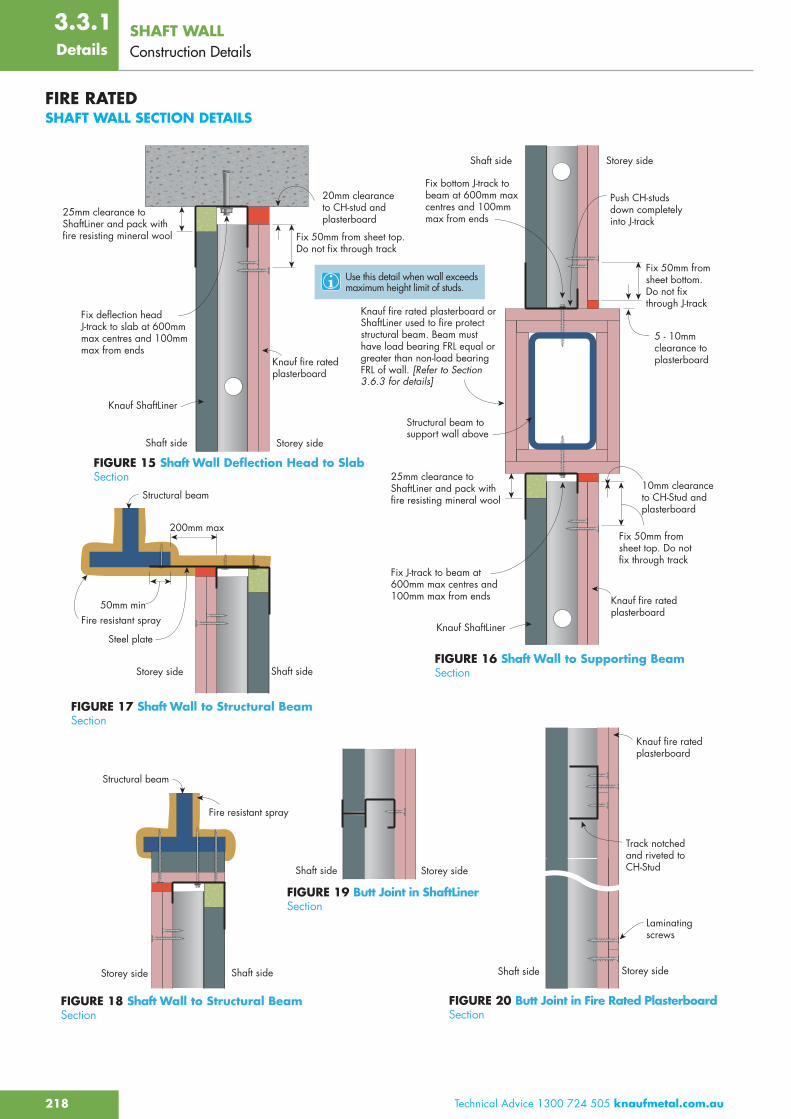
FIRE RATEDSHAFT WALL SECTION DETAILS
Knauf fire rated plasterboard
Knauf fire rated plasterboard
FIGURE 15 Shaft Wall Deflection Head to SlabSection
FIGURE 16 Shaft Wall to Supporting BeamSection
FIGURE 18 Shaft Wall to Structural BeamSection
FIGURE 19 Butt Joint in ShaftLinerSection
FIGURE 17 Shaft Wall to Structural BeamSection
FIGURE 20 Butt Joint in Fire Rated PlasterboardSection
25mm clearance to ShaftLiner and pack with fire resisting mineral wool
Knauf ShaftLiner
Knauf ShaftLiner
Fix deflection head J-track to slab at 600mm max centres and 100mm max from ends
20mm clearance to CH-stud and plasterboard
Shaft side Storey side
Fix 50mm from sheet top. Do not fix through track
Shaft side Storey side
Track notched and riveted to CH-Stud
Laminating screws
Shaft side Storey sideShaft sideStorey side
Fire resistant spray
Structural beam
Shaft sideStorey side
Fire resistant spray
200mm max
50mm min
Steel plate
Structural beam
Push CH-studs down completely into J-track
Fix 50mm from sheet bottom. Do not fix through J-track
Fix bottom J-track to beam at 600mm max centres and 100mm max from ends
5 - 10mm clearance to plasterboard
25mm clearance to ShaftLiner and pack with fire resisting mineral wool
Fix J-track to beam at 600mm max centres and 100mm max from ends
Fix 50mm from sheet top. Do not fix through track
10mm clearance to CH-Stud and plasterboard
Shaft side Storey side
Structural beam to support wall above
Knauf fire rated plasterboard or ShaftLiner used to fire protect structural beam. Beam must have load bearing FRL equal or greater than non-load bearing FRL of wall. [Refer to Section 3.6.3 for details]
Use this detail when wall exceeds maximum height limit of studs.
Knauf fire rated plasterboard
FIRE RATEDSHAFT WALL SECTION DETAILS
SHAFT WALLConstruction Details
219Technical Advice 1300 724 505 knaufplasterboard.com.au
Details
3.3.1
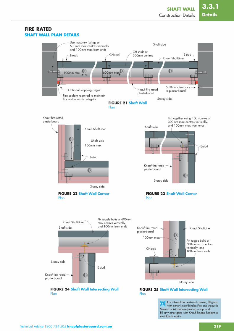
FIRE RATEDSHAFT WALL PLAN DETAILS
FIGURE 21 Shaft WallPlan
FIGURE 22 Shaft Wall CornerPlan
FIGURE 24 Shaft Wall Intersecting WallPlan
FIGURE 23 Shaft Wall CornerPlan
FIGURE 25 Shaft Wall Intersecting WallPlan
Knauf ShaftLiner
Knauf ShaftLiner
Knauf ShaftLiner
Knauf ShaftLiner
Fire sealant required to maintain fire and acoustic integrity
Use masonry fixings at 600mm max centres vertically and 100mm max from ends
J-track CH-stud E-stud
600mm max100mm max
Optional stopping angle5-10mm clearance to plasterboard
CH-studs at 600mm centres
100mm max
E-stud
100mm maxShaft side
Storey side
Shaft side
Storey side
E-stud
Shaft side
Fix together using 10g screws at 300mm max centres vertically, and 100mm max from ends
Storey side
CH-stud
Storey side
E-stud
Shaft side
Storey side
Knauf fire rated plasterboard
Knauf fire rated plasterboard
Knauf fire rated plasterboard
Knauf fire rated plasterboard
Knauf fire rated plasterboard
Fix toggle bolts at 600mm max centres vertically, and 100mm from ends
Fix toggle bolts at 600mm max centres vertically, and 100mm from ends
For internal and external corners, fill gaps with either Knauf Bindex Fire and Acoustic
Sealant or Mastabase jointing compound. Fill any other gaps with Knauf Bindex Sealant to maintain integrity.
FIRE RATEDSHAFT WALL PLAN DETAILS

SHAFT WALLConstruction DetailsDetails
220 Technical Advice 1300 724 505 knaufmetal.com.au
3.3.1
FIRE RATEDSHAFT WALL CONTROL JOINT AND OPENING DETAIL FOR ACCESS PANEL OR FIRE DAMPER
25mm ShaftLiner or2 x 16mm FireShieldaround opening
Jamb stud
Header
SillFire rated plasterboard
ShaftLiner
CH-Stud
Opening for access panel or damper.
Refer to access panel / fire damper manufacturer for specific
installation detail of the proprrietry item. The item installed in the opening must maintain the FRL of the system.
Refer to framing manufacturer for
the design of the jamb, header and sill. Actual framing members for the opening are dependant on the wall height, size of the opening, lateral wind pressure, and the deflection limit criteria.
Fill any gaps with fire sealant to maintain
fire and acoustic integrity.
FIGURE 27 Opening Detail For Fire Damper or Access PanelFire rated from both directions but built from one side only
SectionElevation
FIGURE 26 Shaft Wall Control JointPlan
E-studBacking tape
22mm backing rodTracks discontinuous over control joint
Fire sealant depth same as the plasterboard thickness to maintain fire and acoustic integrityOptional control joint bead
15mm
FIRE RATEDSHAFT WALL CONTROL JOINT AND OPENING DETAIL FOR ACCESS PANEL OR FIRE DAMPER