sf2 mss i2c configuration - amazon web...
TRANSCRIPT
SmartFusion2 MSSI2C Configuration

SmartFusion2 MSS I2C Configuration
2
Table of Contents
Introduction . . . . . . . . . . . . . . . . . . . . . . . . . . . . . . . . . . . . . . . . . . . . . . . . . . . . . . . . . . . . . . . . . . . . . . 3
1 Configuration Options. . . . . . . . . . . . . . . . . . . . . . . . . . . . . . . . . . . . . . . . . . . . . . . . . . . . . . . . . . . . . . . 4
2 Peripheral Signals Assignment Table . . . . . . . . . . . . . . . . . . . . . . . . . . . . . . . . . . . . . . . . . . . . . . . . . . 5
3 Connectivity Preview . . . . . . . . . . . . . . . . . . . . . . . . . . . . . . . . . . . . . . . . . . . . . . . . . . . . . . . . . . . . . . . 6
4 Resource Conflicts . . . . . . . . . . . . . . . . . . . . . . . . . . . . . . . . . . . . . . . . . . . . . . . . . . . . . . . . . . . . . . . . . 7Error Example . . . . . . . . . . . . . . . . . . . . . . . . . . . . . . . . . . . . . . . . . . . . . . . . . . . . . . . . . . . . . . . . . . . . . . . . . . . . . 8
Warning Example . . . . . . . . . . . . . . . . . . . . . . . . . . . . . . . . . . . . . . . . . . . . . . . . . . . . . . . . . . . . . . . . . . . . . . . . . . . 9
Information Example . . . . . . . . . . . . . . . . . . . . . . . . . . . . . . . . . . . . . . . . . . . . . . . . . . . . . . . . . . . . . . . . . . . . . . . 10
5 Port Description . . . . . . . . . . . . . . . . . . . . . . . . . . . . . . . . . . . . . . . . . . . . . . . . . . . . . . . . . . . . . . . . . . 11
A Product Support . . . . . . . . . . . . . . . . . . . . . . . . . . . . . . . . . . . . . . . . . . . . . . . . . . . . . . . . . . . . . . . . . . 12Customer Service . . . . . . . . . . . . . . . . . . . . . . . . . . . . . . . . . . . . . . . . . . . . . . . . . . . . . . . . . . . . . . . . . . . . . . . . . 12
Customer Technical Support Center . . . . . . . . . . . . . . . . . . . . . . . . . . . . . . . . . . . . . . . . . . . . . . . . . . . . . . . . . . . 12
Technical Support . . . . . . . . . . . . . . . . . . . . . . . . . . . . . . . . . . . . . . . . . . . . . . . . . . . . . . . . . . . . . . . . . . . . . . . . . 12
Website . . . . . . . . . . . . . . . . . . . . . . . . . . . . . . . . . . . . . . . . . . . . . . . . . . . . . . . . . . . . . . . . . . . . . . . . . . . . . . . . . 12
Contacting the Customer Technical Support Center . . . . . . . . . . . . . . . . . . . . . . . . . . . . . . . . . . . . . . . . . . . . . . . 12
ITAR Technical Support . . . . . . . . . . . . . . . . . . . . . . . . . . . . . . . . . . . . . . . . . . . . . . . . . . . . . . . . . . . . . . . . . . . . . 13

3
Introduction
The SmartFusion2 Microcontroller Subsystem (MSS) provides two I2C hard peripherals (APB_0 and APB_1 sub busses) with FPFA fabric generated Baud Clock and SMBus FPGA fabric extension.
On the MSS Canvas, you must enable (default) or disable each I2C instance based on whether it is being used in your current application. Disabled I2C instances are held in reset (lowest power state). By default, ports of enabled I2C instances are configured to connect to the device Multi Standard I/Os (MSIOs). Note that MSIOs allocated to an I2C instance are shared with other MSS peripherals. These shared I/Os are available to connect to MSS GPIOs and other peripherals when the I2C instance is disabled or if the I2C instance ports are connected to the FPGA fabric.
The functional behavior of each I2C instance must be defined at the application level using the SmartFusion2 MSS I2C Driver provided by Microsemi.
In this document, we describe how you can configure the MSS I2C instances, access the optional FPGA fabric Baud Clock and SMBus signals and define how the peripheral signals are connected.
For more details about the MSS I2C hard peripherals, please refer to the SmartFusion2 User Guide.
4
1 – Configuration Options
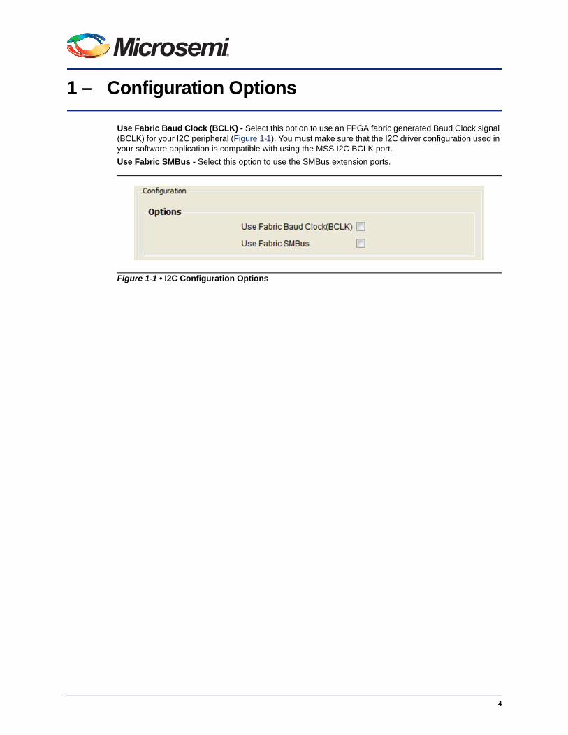
Use Fabric Baud Clock (BCLK) - Select this option to use an FPGA fabric generated Baud Clock signal (BCLK) for your I2C peripheral (Figure 1-1). You must make sure that the I2C driver configuration used in your software application is compatible with using the MSS I2C BCLK port.
Use Fabric SMBus - Select this option to use the SMBus extension ports.
Figure 1-1 • I2C Configuration Options

5
2 – Peripheral Signals Assignment Table
The SmartFusion2 architecture provides a very flexible schema for connecting peripheral signals to either MSIOs or the FPGA fabric. Use the signal assignment configuration table to define what your peripheral is connected to in your application. The assignment table has the following columns (Figure 2-1):
MSIO - Identifies the peripheral signal name configured in a given row.
Main Connection - Use the drop-down list to select whether the signal is connected to an MSIO or the FPGA fabric.
Direction - Idicates if the signal direction is IN, OUT or INOUT.
Package Pin - Shows the package pin associated with the MSIO when the signal is connected to an MSIO.
Extra Connections - Use the Advanced Options check-box to view the extra connection options:
• Select the Fabric option to observe into the FPGA fabric a signal that is connected to an MSIO.
• Select the GPIO option to observe an input direction signal - from either the FPGA fabric or an MSIO - using an MSS GPIO.
Figure 2-1 • I2C Peripheral Signals Assignment Table
6
3 – Connectivity Preview
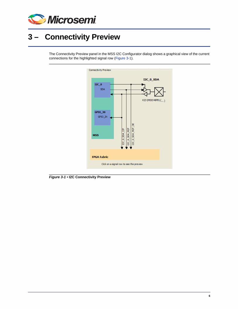
The Connectivity Preview panel in the MSS I2C Configurator dialog shows a graphical view of the current connections for the highlighted signal row (Figure 3-1).
Figure 3-1 • I2C Connectivity Preview

4 – Resource Conflicts
Because MSS peripherals (MMUART, I2C, SPI, CAN, GPIO, USB, Ethernet MAC) share MSIO and FPGA fabric access resources, the configuration of any of these peripherals may result in a resource conflict when you configure an instance of the current peripheral. Peripheral configurators provide clear indicators when such a conflict arises.
Resources used by a previously configured peripheral result in three types of feedback in the current peripheral configurator:
• Information - If a resource used by another peripheral does not conflict with the current configuration, an information icon apepars in the connectivity preview panel, on that resource. A tooltip on the icon provides details about which peripheral uses that resource.
• Warning/Error - If a resource used by another peripheral conflicts with the current configuration, a warning or error icon appears in the connectivity preview panel, on that resource. A tooltip on the icon provides details about which peripheral uses that resource.
When errors are displayed you will not be able to commit the current configuration. You can either resolve the conflict by using a different configuration or cancel the current configuration using the Cancel button.
When warnings are displayed (and there are no errors), you can commit the current configuration. However, you cannot generate the overall MSS; you will see generation errors in the Libero SoC log window. You must resolve the conflict that you created when you committed the configuration by re-configuring either of the peripherals causing the conflict.
The peripheral configurators implement the following rules to determine if a conflict should be reported as an error or a warning.
1. If the peripheral being configured is the GPIO peripheral then all conflicts are errors.
2. If the peripheral being configured is not the GPIO peripheral then all conflicts are errors unless the conflict is with a GPIO resource in which case conflicts will be treated as warnings.
7
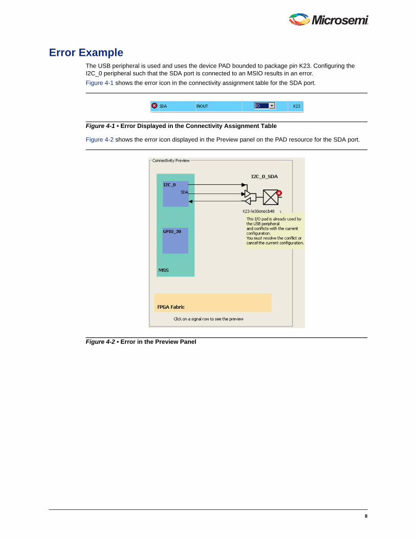
Error ExampleThe USB peripheral is used and uses the device PAD bounded to package pin K23. Configuring the I2C_0 peripheral such that the SDA port is connected to an MSIO results in an error.
Figure 4-1 shows the error icon in the connectivity assignment table for the SDA port.
Figure 4-2 shows the error icon displayed in the Preview panel on the PAD resource for the SDA port.
Figure 4-1 • Error Displayed in the Connectivity Assignment Table
Figure 4-2 • Error in the Preview Panel
8
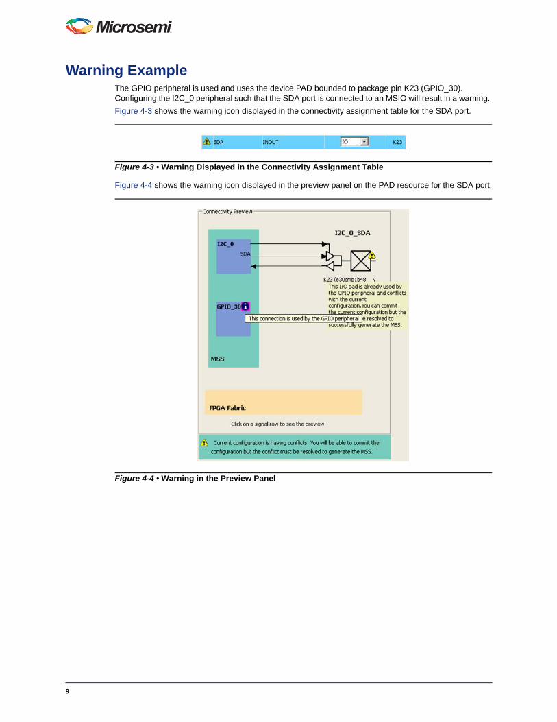
Warning ExampleThe GPIO peripheral is used and uses the device PAD bounded to package pin K23 (GPIO_30). Configuring the I2C_0 peripheral such that the SDA port is connected to an MSIO will result in a warning.
Figure 4-3 shows the warning icon displayed in the connectivity assignment table for the SDA port.
Figure 4-4 shows the warning icon displayed in the preview panel on the PAD resource for the SDA port.
Figure 4-3 • Warning Displayed in the Connectivity Assignment Table
Figure 4-4 • Warning in the Preview Panel
9
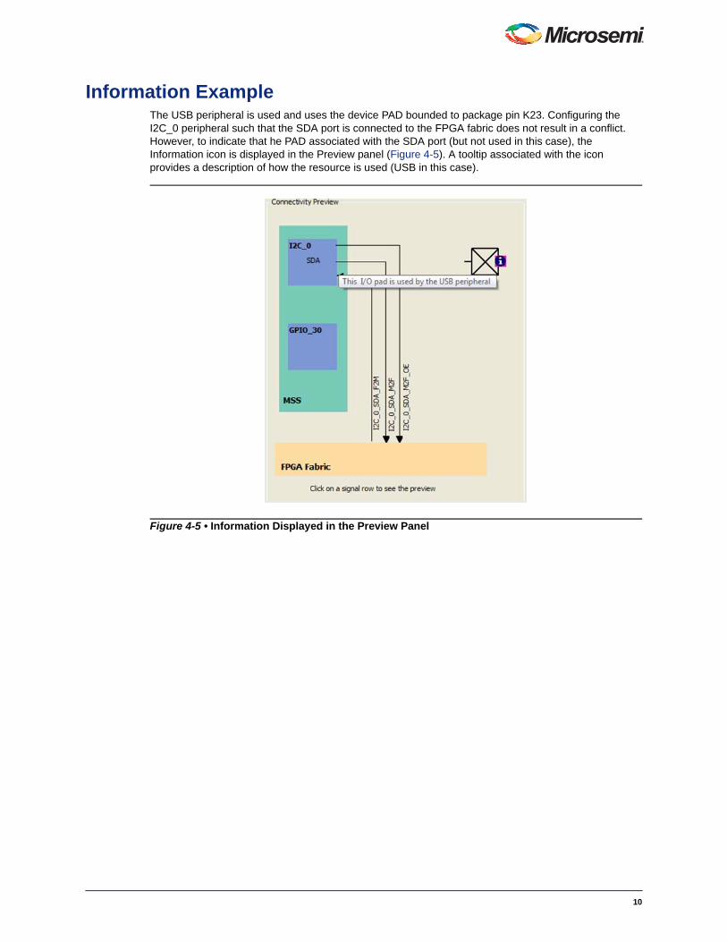
Information ExampleThe USB peripheral is used and uses the device PAD bounded to package pin K23. Configuring the I2C_0 peripheral such that the SDA port is connected to the FPGA fabric does not result in a conflict. However, to indicate that he PAD associated with the SDA port (but not used in this case), the Information icon is displayed in the Preview panel (Figure 4-5). A tooltip associated with the icon provides a description of how the resource is used (USB in this case).
Figure 4-5 • Information Displayed in the Preview Panel
10

11
5 – Port Description
Note:
• Port names have the name of the I2C instance as a prefix, e.g. I2C_<n>_SDA.
• Fabric main connection input ports names have "F2M" as a suffix, e.g. I2C _<n>_SDA_F2M.
• Fabric extra connection input ports names have "I2F" as a suffix, e.g. I2C_<n>_SDA_I2F.
• Fabric output and output-enable ports names have "M2F and "M2F_OE" as a suffix, e.g. I2C_<n>_SDA_M2F and I2C_<n>_ SDA_M2F_OE.
• PAD ports are automatically promoted to top throughout the design hierarchy.
Table 5-1 • Port Description
Port Name Port Group Direction Description
SDA I2C_<n>_PADS / I2C_<n>_FABRIC Inout External dedicated serial Interface.
Wired-AND serial data input/output.
SCL I2C_<n>_PADS / I2C_<n>_FABRIC Inout External dedicated serial Interface.
Wired-AND serial clock input/output.
BCLK I2C_<n>_BCLK In Pulse for SCL speed control. Overrides PCLK when used.
SMBSUS_NI I2C_<n>_ FABRIC_SMBUS In Input Suspend Mode signal; used if Core is slave/device.
NOTE: Not a Wired-AND signal.
SMBALERT_NI I2C_<n>_FABRIC_SMBUS In Wired-AND interrupt signal; used in master/host mode to monitor if slave/devices want to force communication with the host.
SMBSUS_NO I2C_<n>_FABRIC_SMBUS Out Suspend Mode signal; used if Core is the master/host.
NOTE: Not a Wired-AND signal.
SMBALERT_NO I2C_<n>_FABRIC_SMBUS Out Wired-AND interrupt signal; used in slave/device mode if the Core wants to force communication with a host.

A – Product Support
Microsemi SoC Products Group backs its products with various support services, including Customer Service, Customer Technical Support Center, a website, electronic mail, and worldwide sales offices. This appendix contains information about contacting Microsemi SoC Products Group and using these support services.
Customer ServiceContact Customer Service for non-technical product support, such as product pricing, product upgrades, update information, order status, and authorization.
From North America, call 800.262.1060From the rest of the world, call 650.318.4460Fax, from anywhere in the world, 408.643.6913
Customer Technical Support CenterMicrosemi SoC Products Group staffs its Customer Technical Support Center with highly skilled engineers who can help answer your hardware, software, and design questions about Microsemi SoC Products. The Customer Technical Support Center spends a great deal of time creating application notes, answers to common design cycle questions, documentation of known issues, and various FAQs. So, before you contact us, please visit our online resources. It is very likely we have already answered your questions.
Technical SupportVisit the Customer Support website (www.microsemi.com/soc/support/search/default.aspx) for more information and support. Many answers available on the searchable web resource include diagrams, illustrations, and links to other resources on the website.
WebsiteYou can browse a variety of technical and non-technical information on the SoC home page, at www.microsemi.com/soc.
Contacting the Customer Technical Support CenterHighly skilled engineers staff the Technical Support Center. The Technical Support Center can be contacted by email or through the Microsemi SoC Products Group website.
EmailYou can communicate your technical questions to our email address and receive answers back by email, fax, or phone. Also, if you have design problems, you can email your design files to receive assistance. We constantly monitor the email account throughout the day. When sending your request to us, please be sure to include your full name, company name, and your contact information for efficient processing of your request.
The technical support email address is [email protected].
12

MOWSaFa
Microsemi Corporation (NASDAQ: MSCC) offers a comprehensive portfolio of semiconductorsolutions for: aerospace, defense and security; enterprise and communications; and industrialand alternative energy markets. Products include high-performance, high-reliability analogand RF devices, mixed signal and RF integrated circuits, customizable SoCs, FPGAs, andcomplete subsystems. Microsemi is headquartered in Aliso Viejo, Calif. Learn more atwww.microsemi.com.
icrosemi Corporate Headquarters
My CasesMicrosemi SoC Products Group customers may submit and track technical cases online by going to My Cases.
Outside the U.S.Customers needing assistance outside the US time zones can either contact technical support via email ([email protected]) or contact a local sales office. Sales office listings can be found at www.microsemi.com/soc/company/contact/default.aspx.
ITAR Technical SupportFor technical support on RH and RT FPGAs that are regulated by International Traffic in Arms Regulations (ITAR), contact us via [email protected]. Alternatively, within My Cases, select Yes in the ITAR drop-down list. For a complete list of ITAR-regulated Microsemi FPGAs, visit the ITAR web page.
5-02-00347-0/03.12
© 2012 Microsemi Corporation. All rights reserved. Microsemi and the Microsemi logo are trademarks ofMicrosemi Corporation. All other trademarks and service marks are the property of their respective owners.
ne Enterprise, Aliso Viejo CA 92656 USAithin the USA: +1 (949) 380-6100les: +1 (949) 380-6136x: +1 (949) 215-4996