setup guide - kikusui
TRANSCRIPT

PAT-T series 1
Thank you for purchasing the PAT-T Series Regulated DC Power Supply.
The PAT-T Series is a low-noise, highly efficient Constant Voltage (CV)/ Constant Current (CC) automatic crossover power supply that employs a software switching system.
PAT-T Series modelsThe PAT-T Series consists of the 4 kW type and 8 kW type. On the 4 kW type, you can select the input mode: single-phase input or three-phase input. The 8 kW type is three-phase input. The 8 kW type consists of the 200 V input model and 400 V input model (200 V input only for the PAT1000-8T/PAT1500-5.3T).
Output power Model Input mode Rated voltage Input rating4 kW type PAT20-200T Single-
phase/ three-phase selectable
20 V 200 V
PAT40-100T 40 V
PAT60-67T 60 V
PAT160-25T 160 V8 kW type PAT20-400T Three-phase 20 V 200 V
400 VPAT30-266T Three-phase 30 V 200 V
400 VPAT40-200T Three-phase 40 V 200 V
400 VPAT60-133T Three-phase 60 V 200 V
400 VPAT80-100T Three-phase 80 V 200 V
400 VPAT160-50T Three-phase 160 V 200 V
400 VPAT250-32T Three-phase 250 V 200 V
400 VPAT350-22.8T Three-phase 350 V 200 V
400 VPAT500-16T Three-phase 500 V 200 V
400 VPAT650-12.3T Three-phase 650 V 200 V
400 VPAT850-9.4T Three-phase 850 V 200 V
400 VPAT1000-8T Three-phase 1000 V 200 VPAT1500-5.3T Three-phase 1500 V 200 V
Checking the Package ContentsWhen you receive the product, check that all accessories are included and that the accessories have not been damaged during transportation. If any of the accessories are damaged or missing, contact your Kikusui agent or distributor. We recommend that you save all packing materials, in case the product needs to be transported at a later date.
Accessory
● 4 kW type/ 8 kW type
CD-ROM (1 pc.)
[M3-112-059]OUTPUT terminal cover [Q1-500-106]
OUTPUT terminal cover set
J1/J2 connector kit
Pins 30 pcs.[84-49-0100]
Pins 30 pcs.[84-49-0100]
Socket 2 pcs.[84-49-0160]
Socket 2 pcs.[84-49-0160]Protection cover
2 sets [84-49-0161]
Protection cover 2 sets [84-49-0140]
Chassis connection wire set (1 set)
Output terminal bolt set (2 sets)* Not included with the PAT1000-8T/PAT1500-5.3T
Setup Guide (1pc.) Quick Reference(Japanese: 1pc.,English: 1pc.)
Safety information (1pc.)Heavy object warning label (1 pc.) [A8-900-153]
If necessary, attach to the product.
[91-80-6940]
[M3-112-027]
x 2
[1][2]
[3]
Model of rated output 20 V to 850 V (2 sets)
Model of rated output 20 V to 850 V
* Chassis connection wire only for the PAT1000-8T/PAT1500-5.3T
Model of rated output 1000 V, 1500V
4 kW type 8 kW typeRated voltage
20 V to 160 V 20 V, 30 V 40 V to 160 V 250 V to 850 V
Size M10 set M12 set M10 set M8 set[1] M1-100-119 M1-100-127 M1-100-119 M1-100-113
[2] M5-101-008 M5-101-009 M5-101-008 M5-101-007[3] M4-100-008 M4-100-009 M4-100-008 M4-100-007
PART NO. Z1-005-610, I0027801Oct 2020
PAT20-400TPAT30-266TPAT40-200TPAT60-133TPAT80-100TPAT160-50T
Setup GuideRegulated DC Power Supply PAT-T series
8kW type4kW typePAT250-32TPAT350-22.8TPAT500-16TPAT650-12.3TPAT850-9.4T
PAT20-200TPAT40-100TPAT60-67TPAT160-25T
PAT1000-8T (SPEC21163)PAT1500-5.3T (SPEC21164)
8kW type (Custom model)
KIKUSUI ELECTRONICS CORP.1-1-3 Higashiyamata, Tsuzuki-ku, Yokohama, 224-0023, Japan
Tel: +81-45-482-6353 Fax: +81-45-482-6261www.kikusui.co.jp/en
2 PAT-T series
FeaturesThe PAT-T Series is equipped with the following features.
• Reduction of harmonic current and power transmission lossThe power-factor improvement circuit reduces the effects of harmonic currents on the input power line. It also suppresses the peak current and reduces the power transmission loss.
• Master-Slave parallel operationUp to five power supplies can be connected in parallel to expand.
• Output limit functionYou can set the upper limit of current and voltage that is applied when setting the output. This function is used to prevent setting inappropriate value by mistake.
• Remote interfaceEquipped with RS232C as standard. You can select the GPIB, USB or LAN interface as a factory option. The remote interface complies with IEEE 488.2 std 1992 and SCPI Specification 1999.0. Because the LAN interface complies with the LXI standard, the construction of a highly cost-effective system is possible.
• High efficiency and low noiseThe PAT is a highly efficient, low-noise power supply that employs a software switching system. High power conversion efficiency has reduced the rise in the internal temperature and has contributed to the product’s compact and light design.
• Downsized input distribution deviceThe input distribution device (breaker) can be downsized, because the built-in power-factor improvement circuit reduces the required input current.
• Preset memory function of settingsUp to three output setting presets (combination of current and voltage) can be saved. You can simply select a preset to set the output without having to set the voltage and current every time you use the PAT.
• Output on/off delay functionYou can set a delay until the output is actually turned on or off after turning the OUTPUT switch on or off. For example, this feature is useful if you want to turn the output on/off by setting a time offset according to the load characteristics.
• Selectable input power for the three-phase input mode or single-phase input mode (Only 4 kW type)The input power mode can be switched from “three-phase input to single-phase input” or “single-phase input to three-phase input” by the CONFIG setting. In the single- phase input mode, output current is limited to 75 % of the rating of three-phase input mode.
Precautions Concerning Installation• Avoid locations where the product is exposed to high
temperature or direct sunlight.Do not install the product near a heater or in areas subject to drastic temperature changes.
Operating temperature range: 0 °C to +50 °C (32 °F to 122 °F)Storage temperature range: -25 °C to +70 °C (-13 °F to 158 °F)
• Avoid humid environments.Do not install the product in high-humidity locations–near a boiler, humidifier, or water supply.Operating humidity range: 20 %rh to 85 %rh (no condensation)Storage humidity range: 90 %rh or less (no condensation)Condensation may occur even within the operating relative humidity range. If this happens, do not use the product until the condensation dries up completely.
These manual is intended for users of the product or persons teaching other users on how to operate the product.
The manual assumes that the reader has knowledge about Power Supply.
The Operation Manual has been prepared with the utmost care; however, if you have any questions, or note any errors or omissions, please contact Kikusui distributor/agent.
If you find any incorrectly arranged or missing pages in the manual, they will be replaced. If the manual gets lost or soiled, a new copy can be provided for a fee. In either case, please contact Kikusui distributor/agent, and provide the “Kikusui Part No.” given on the cover.
After reading, always keep the manual nearby so that you may
refer to it as needed.
Documentation Structure
■User's manual (PDF)The User’s manual is intended for first-time users of this product. It provides an overview of the product and notes on usage. It also explains how to configure the product, operate the product, perform maintenance on the product, and so on.
■ Setup Guide (This guide)This guide is intended for first-time users of the product. It gives an overview of the product, connecting procedures, etc. Please read through and understand this guide before operating the product.
■Quick ReferenceThe quick reference briefly explains the panel description and the basic operation of the product.
■ Safety informationThis document contains general safety precautions for this product. Keep them in mind and make sure to observe them.
■Communication Interface Manual (HTML, PDF)This manual contains details about remote control.
Interface manual is written for readers with sufficient basic knowledge of how to control instruments using a personal computer.
About the PAT-T Documentation
PAT-T series 3
About the PAT-T Documentation
Notations used in the PAT-T manual
In this manual, the PAT-T Series regulated DC power supply is often simply referred to as "the PAT."
The word "PC" used in this manual is a generic term for personal computers and workstations.
The screen captures used in this manual may differ from the actual screens that appear on the PAT-T. The screen captures are merely examples.
The following markings are used in the explanations in the manual.
WARNINGIndicates a potentially hazardous situation which, if ignored, could result in death or serious injury.
CAUTIONIndicates a potentially hazardous situation which, if ignored, may result in damage to the product or other property.
- Note -
Indicates information that you should know.
- DESCRIPTION -
Explanation of terminology or operation principle.
(SHIFT+key name)
Indicates an operation in which a switch marked in blue is pressed while holding down the SHIFT key.
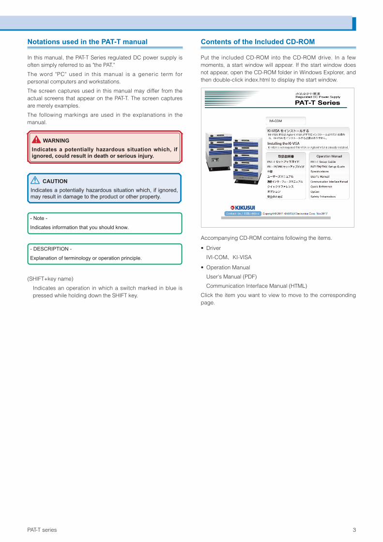
Contents of the Included CD-ROM
Put the included CD-ROM into the CD-ROM drive. In a few moments, a start window will appear. If the start window does not appear, open the CD-ROM folder in Windows Explorer, and then double-click index.html to display the start window.
Accompanying CD-ROM contains following the items.
• Driver
IVI-COM、KI-VISA
• Operation Manual
User's Manual (PDF)
Communication Interface Manual (HTML)
Click the item you want to view to move to the corresponding page.
4 PAT-T series
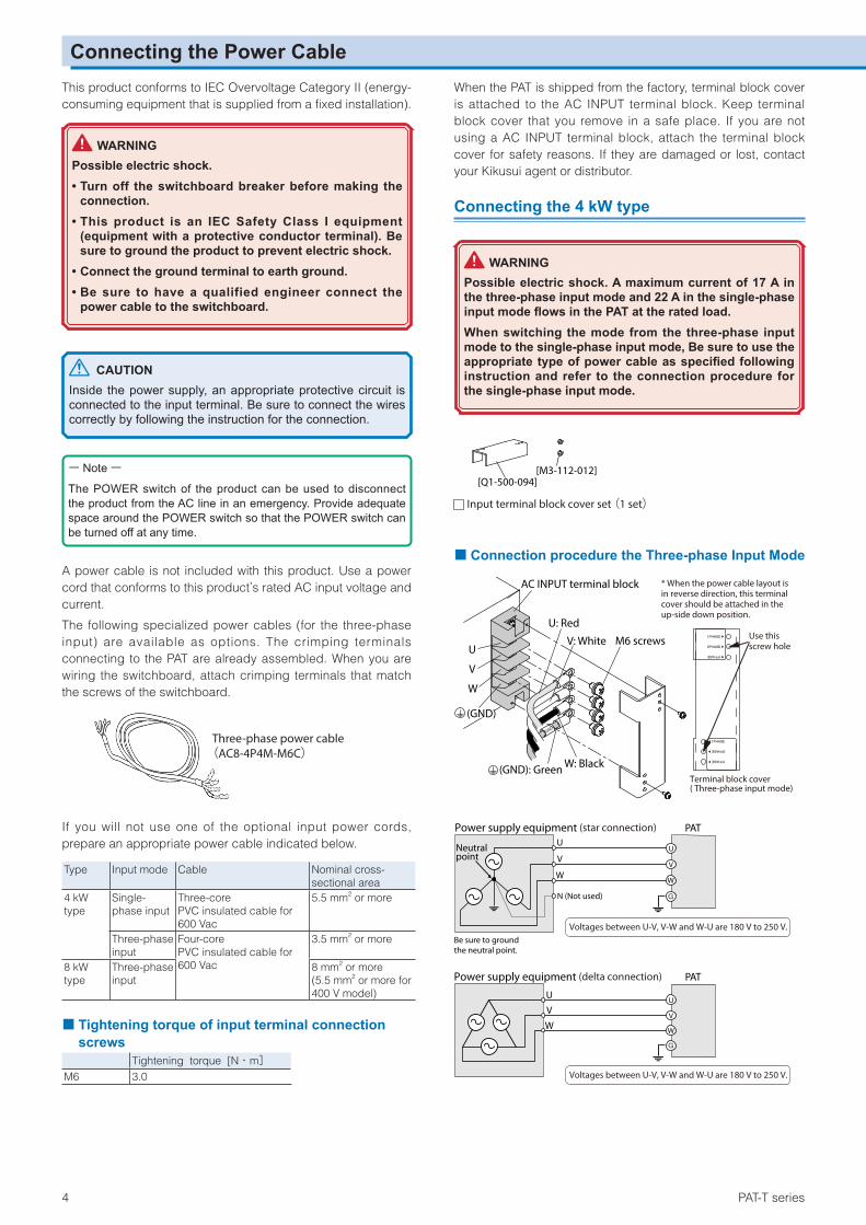
This product conforms to IEC Overvoltage Category II (energy-consuming equipment that is supplied from a fixed installation).
WARNINGPossible electric shock.• Turn off the switchboard breaker before making the
connection.• This product is an IEC Safety Class I equipment
(equipment with a protective conductor terminal). Be sure to ground the product to prevent electric shock.
• Connect the ground terminal to earth ground.• Be sure to have a qualified engineer connect the
power cable to the switchboard.
CAUTIONInside the power supply, an appropriate protective circuit is connected to the input terminal. Be sure to connect the wires correctly by following the instruction for the connection.
ー NoteーThe POWER switch of the product can be used to disconnect the product from the AC line in an emergency. Provide adequate space around the POWER switch so that the POWER switch can be turned off at any time.
A power cable is not included with this product. Use a power cord that conforms to this product’s rated AC input voltage and current.
The following specialized power cables (for the three-phase input) are available as options. The crimping terminals connecting to the PAT are already assembled. When you are wiring the switchboard, attach crimping terminals that match the screws of the switchboard.
Three-phase power cable(AC8-4P4M-M6C)
If you will not use one of the optional input power cords, prepare an appropriate power cable indicated below.
Type Input mode Cable Nominal cross-sectional area
4 kW type
Single-phase input
Three-core PVC insulated cable for 600 Vac
5.5 mm2 or more
Three-phase input
Four-core PVC insulated cable for 600 Vac
3.5 mm2 or more
8 kW type
Three-phase input
8 mm2 or more (5.5 mm2 or more for 400 V model)
■ Tightening torque of input terminal connection screws
Tightening torque [N・m]M6 3.0
When the PAT is shipped from the factory, terminal block cover is attached to the AC INPUT terminal block. Keep terminal block cover that you remove in a safe place. If you are not using a AC INPUT terminal block, attach the terminal block cover for safety reasons. If they are damaged or lost, contact your Kikusui agent or distributor.
Connecting the 4 kW type
WARNINGPossible electric shock. A maximum current of 17 A in the three-phase input mode and 22 A in the single-phase input mode flows in the PAT at the rated load.When switching the mode from the three-phase input mode to the single-phase input mode, Be sure to use the appropriate type of power cable as specified following instruction and refer to the connection procedure for the single-phase input mode.
[Q1-500-094][M3-112-012]
Input terminal block cover set (1 set)
■Connection procedure the Three-phase Input Mode
GND
(GND)
W
V
U
AC INPUT terminal block
V: White
U: Red
M6 screws
(GND): Green W: Black
* When the power cable layout is in reverse direction, this terminalcover should be attached in the up-side down position.
Use this screw hole
Terminal block cover( Three-phase input mode)
Power supply equipment (star connection) PAT
G
U
V
W
U
V
W
Be sure to ground the neutral point.
Voltages between U-V, V-W and W-U are 180 V to 250 V.
Voltages between U-V, V-W and W-U are 180 V to 250 V.
U
V
W
Neutral point
N (Not used)
Power supply equipment (delta connection) PAT
G
U
V
W
Connecting the Power Cable
PAT-T series 5
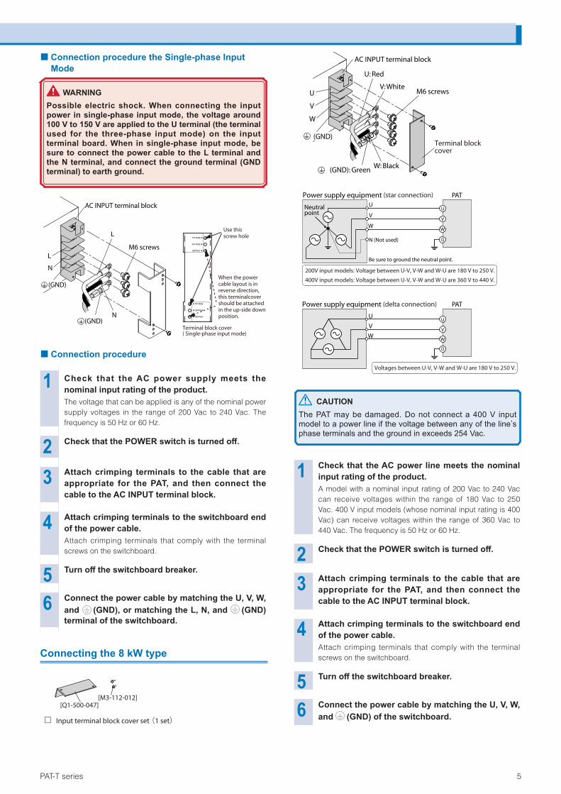
■Connection procedure the Single-phase Input Mode
WARNINGPossible electric shock. When connecting the input power in single-phase input mode, the voltage around 100 V to 150 V are applied to the U terminal (the terminal used for the three-phase input mode) on the input terminal board. When in single-phase input mode, be sure to connect the power cable to the L terminal and the N terminal, and connect the ground terminal (GND terminal) to earth ground.
GND
(GND)
(GND)N
L
N
L
AC INPUT terminal block
M6 screws
Use this screw hole
Terminal block cover( Single-phase input mode)
When the power cable layout is in reverse direction, this terminalcover should be attached in the up-side down position.
■Connection procedure
1 Check that the AC power supply meets the nominal input rating of the product.The voltage that can be applied is any of the nominal power supply voltages in the range of 200 Vac to 240 Vac. The frequency is 50 Hz or 60 Hz.
2 Check that the POWER switch is turned off.
3 Attach crimping terminals to the cable that are appropriate for the PAT, and then connect the cable to the AC INPUT terminal block.
4 Attach crimping terminals to the switchboard end of the power cable.Attach crimping terminals that comply with the terminal screws on the switchboard.
5 Turn off the switchboard breaker.
6 Connect the power cable by matching the U, V, W, and (GND), or matching the L, N, and (GND)terminal of the switchboard.
Connecting the 8 kW type
Input terminal block cover set (1 set)
[Q1-500-047][M3-112-012]
GND (GND)
W
V
U
AC INPUT terminal block
V: White
U: Red
M6 screws
(GND): GreenW: Black
Terminal block cover
Power supply equipment (star connection) PAT
N (Not used) G
U
V
W
U
V
W
Be sure to ground the neutral point.
200V input models: Voltage between U-V, V-W and W-U are 180 V to 250 V.
400V input models: Voltage between U-V, V-W and W-U are 360 V to 440 V.
U
V
W
Neutral point
Power supply equipment (delta connection) PAT
G
U
V
W
Voltages between U-V, V-W and W-U are 180 V to 250 V.
CAUTIONThe PAT may be damaged. Do not connect a 400 V input model to a power line if the voltage between any of the lineʼs phase terminals and the ground in exceeds 254 Vac.
1 Check that the AC power line meets the nominal input rating of the product.A model with a nominal input rating of 200 Vac to 240 Vac can receive voltages within the range of 180 Vac to 250 Vac. 400 V input models (whose nominal input rating is 400 Vac) can receive voltages within the range of 360 Vac to 440 Vac. The frequency is 50 Hz or 60 Hz.
2 Check that the POWER switch is turned off.
3 Attach crimping terminals to the cable that are appropriate for the PAT, and then connect the cable to the AC INPUT terminal block.
4 Attach crimping terminals to the switchboard end of the power cable.Attach crimping terminals that comply with the terminal screws on the switchboard.
5 Turn off the switchboard breaker.
6 Connect the power cable by matching the U, V, W, and (GND) of the switchboard.
Connecting the Power Cable
6 PAT-T series
Turning the Power On
CAUTIONThe CONFIG parameters can be configured so that the output is automatically turned on when the POWER switch is turned on. When this function is enabled, the PAT powers up with the output turned on even if the output was off when the PAT was turned off the last time. However, there is a possibility that a load may break, if you connect a different load and turn the POWER and output on simultaneously without changing the OVP and OCP settings to appropriate values.
Switching the phase input mode (Only 4 kW type)
On the 4 kW type, you can use CONFIG parameter CF31 to switch the input mode (single-phase input or three-phase input).
■ Three-phase input modeThe phase input mode is set for the three-phase input mode at the time of factory shipment. Therefore, when the power is turned on, the three-phase input mode is activated.
■ Single-phase input modeSet CONFIG parameter CF31 to 1PHA to select single-phase input mode. Press the POWER switch to turn on while pressing the STORE key. Once the single-phase input mode is set, the product will be started in the single-phase input mode next time just by pressing the POWER switch. If the input power connected to the single-phase input wiring, and press the POWER switch without pressing the STORE key, the PAT will detect the open-phase by the function of “Input open-phase protection (PHASE)”, and the PAT will not be turned on.
Turning the POWER switch on
1 Check that the power cable is correct ly connected.
2 Raise the lever and turn the POWER switch on.
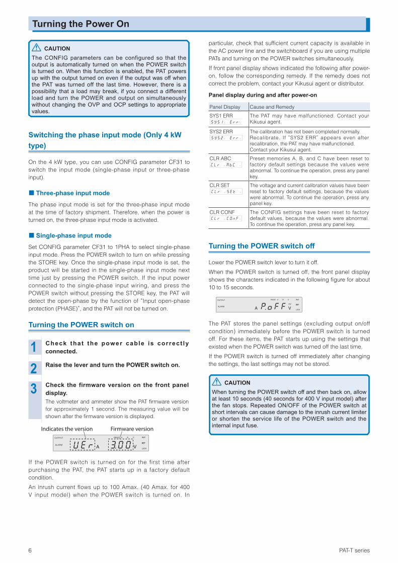
3 Check the firmware version on the front panel display.The voltmeter and ammeter show the PAT firmware version for approximately 1 second. The measuring value will be shown after the firmware version is displayed.
EXTEXT
RMT
LOCK
PRESET A B C
A V
OUTPUT
ALARM
Indicates the version Firmware version
If the POWER switch is turned on for the first time after purchasing the PAT, the PAT starts up in a factory default condition.
An inrush current flows up to 100 Amax. (40 Amax. for 400 V input model) when the POWER switch is turned on. In
particular, check that sufficient current capacity is available in the AC power line and the switchboard if you are using multiple PATs and turning on the POWER switches simultaneously.
If front panel display shows indicated the following after power-on, follow the corresponding remedy. If the remedy does not correct the problem, contact your Kikusui agent or distributor.
Panel display during and after power-on
Panel Display Cause and Remedy
SYS1 ERR A V
The PAT may have malfunctioned. Contact your Kikusui agent.
SYS2 ERR A V
The calibration has not been completed normally.Recalibrate. If “SYS2 ERR” appears even after recalibration, the PAT may have malfunctioned.Contact your Kikusui agent.
CLR ABC A V
Preset memories A, B, and C have been reset to factory default settings because the values were abnormal. To continue the operation, press any panelkey.
CLR SET A V
The voltage and current calibration values have been reset to factory default settings, because the values were abnormal. To continue the operation, press any panel key.
CLR CONF A V
The CONFIG settings have been reset to factory default values, because the values were abnormal. To continue the operation, press any panel key.
Turning the POWER switch off
Lower the POWER switch lever to turn it off.
When the POWER switch is turned off, the front panel display shows the characters indicated in the following figure for about 10 to 15 seconds.
EXTEXT
RMT
LOCK
PRESET A B C
A V
OUTPUT
ALARMCV
The PAT stores the panel settings (excluding output on/off condition) immediately before the POWER switch is turned off. For these items, the PAT starts up using the settings that existed when the POWER switch was turned off the last time.
If the POWER switch is turned off immediately after changing the settings, the last settings may not be stored.
CAUTIONWhen turning the POWER switch off and then back on, allow at least 10 seconds (40 seconds for 400 V input model) after the fan stops. Repeated ON/OFF of the POWER switch at short intervals can cause damage to the inrush current limiter or shorten the service life of the POWER switch and the internal input fuse.
PAT-T series 7
Connecting the LoadNote that the output will become unstable if the following types of loads are connected.
• Load with peaks and pulse-shaped current
• Load that generates reverse current to the power supply
• Load with accumulated energy
Load Cable
WARNINGTo prevent the possibility of fire.• Use a load cable with sufficient current capacity with
respect to the rated output current of the PAT.• The output terminal and its area nearby gets very high
temperature, use the cable with sufficient an allowable temperature higher than 85 °C of the covering materials.
Possible electric shock.• Use a load cable with a higher voltage rating than the
isolation voltage of the PAT. For the isolation voltage of each model, see "Specifications."
Nominal cross-sectional area of cables and allowable currents
Nominal cross-sectional area [mm2]
AWG (Reference cross-sectional area) [mm2]
Allowable current * [A] (Ta = 30 °C, 86 °F)
Kikusui-recommended current (A)
2 14 (2.08) 27 103.5 12 (3.31) 37 -5.5 10 (5.26) 49 208 8 (8.37) 61 3014 6 (13.3) 88 5022 4 (21.15) 115 8030 2 (33.62) 139 -38 1 (42.41) 162 10050 1/0 (53.49) 190 -60 2/0 (67.43) 217 -80 3/0 (85.01) 257 200100 4/0 (107.2) 298 -125 - - 344 -150 - - 395 300200 - - 469 400
* Excerpts from Japanese laws related to electrical equipment.
Connecting to the Output terminal
WARNINGPossible electric shock.• Be sure to turn the POWER switch off before touching
the output terminal.• Be sure to attach the OUTPUT terminal cover after
wiring the load.
■ Tightening torque of output terminal connection screws
Tightening torque [N・m]M4 1.2M8 11.22M10 22.46M12 33.06
■Model of rated output 20 V to 850 V
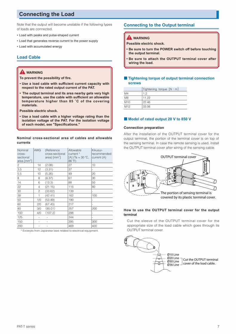
Connection preparationAfter the installation of the OUTPUT terminal cover for the output terminal, the portion of the terminal cover is on top of the sensing terminal. In case the remote sensing is used, install the OUTPUT terminal cover after wiring of the sensing cable.
OUTPUT terminal cover
The portion of sensing terminal iscovered by its plastic terminal cover.
How to use the OUTPUT terminal cover for the output terminal
Cut the sleeve of the OUTPUT terminal cover for the appropriate size of the load cable which goes through its OUTPUT terminal cover.
Ø20 LineØ10 Line
Ø30 LineØ36 Line
Ø10
Ø20
Ø30
Ø36
Cut the OUTPUT terminalcover of the load cable.

8 PAT-T series
Connection procedure
1 Turn the POWER switch off.
2 Using the chassis connection wire set that comes with the package, connect the chassis terminal to either the negative or positive DC output terminal.The output terminal has a hole used to connect the chassis connection cable that comes with the package.
Chassis connection wireScrew
4 kW type
Rated voltage
20 V to 160 V
Size M10 set
8 kW type
Rated voltage
20 V, 30 V 40 V to 160 V
250 V to 850 V
1000 V, 1500 V
Size M12 set M10 set M8 set M4
3 Attach crimping terminals to the load cable.The output terminal has a hole for connecting the load cable. Attach the crimping terminal that matches the bolt used.
4 Insert the load cable through the OUTPUT terminal cover.
5 Connect the load cable on the rear panel.Insert the bolt for the positive (+) terminal from right side, and the negative (-) terminal from left side as you face, then fix it using the nut and spring washers. Connect the load cable straight forward (vertical angle against the surface of the output terminal).
Spring washerNut
Crimp terminalOUTPUT terminal cover
Bolt
Connecting the Load (Contʼd)
6 Install the OUTPUT terminal cover on the rear panel.Uses the attached screws to install the OUTPUT terminal cover firmly and make sure they are not loosen.
Screw
OUTPUT terminal cover
PAT-T series 9
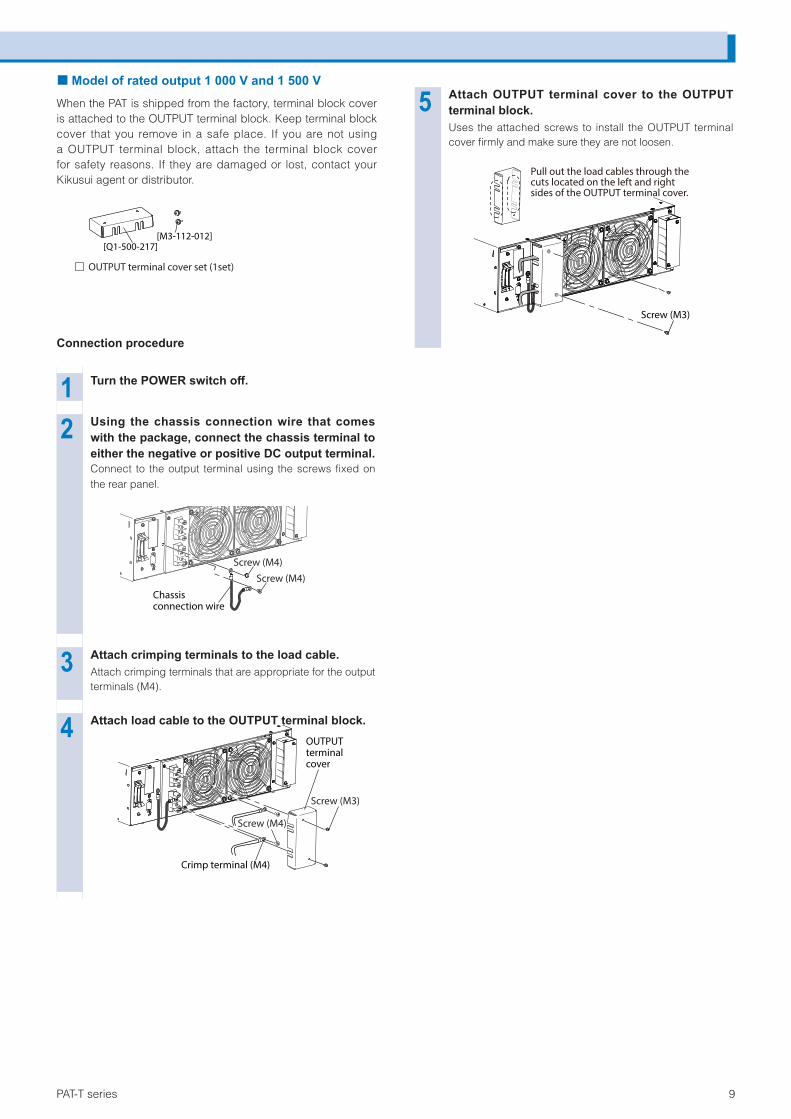
Connecting the Load (Contʼd) ■Model of rated output 1 000 V and 1 500 V
When the PAT is shipped from the factory, terminal block cover is attached to the OUTPUT terminal block. Keep terminal block cover that you remove in a safe place. If you are not using a OUTPUT terminal block, attach the terminal block cover for safety reasons. If they are damaged or lost, contact your Kikusui agent or distributor.
[Q1-500-217][M3-112-012]
OUTPUT terminal cover set (1set)
Connection procedure
1 Turn the POWER switch off.
2 Using the chassis connection wire that comes with the package, connect the chassis terminal to either the negative or positive DC output terminal.Connect to the output terminal using the screws fixed on the rear panel.
Screw (M4)
Screw (M4)
Chassis connection wire
3 Attach crimping terminals to the load cable.Attach crimping terminals that are appropriate for the output terminals (M4).
4 Attach load cable to the OUTPUT terminal block.
Screw (M4)
Screw (M3)
Crimp terminal (M4)
OUTPUT terminal cover
5 Attach OUTPUT terminal cover to the OUTPUT terminal block.Uses the attached screws to install the OUTPUT terminal cover firmly and make sure they are not loosen.
Pull out the load cables through the cuts located on the left and right sides of the OUTPUT terminal cover.
Screw (M3)

10 PAT-T series
TrademarksMicrosoft and Windows are registered trademarks of Microsoft Corporation in the United States and/or other countries.
Other company names and product names used in this manual are generally trademarks or registered trademarks of the respective companies.
■CopyrightReproduction and reprinting of this operation manual, whole or partially, without our permission is prohibited.
Both unit specifications and manual contents are subject to change without notice.
© 2012
10 环境保护使用期限Environment-friendly Use Period
该标记为适用于在中华人民共和国销售的电子信息产品的环境保护使用期限。
只要遵守有关该产品的安全及使用注意事项,从制造年月起计算,在该年度内,就不会对环境污染、人身、财产产生重大的影响。
产品的废弃请遵守有关规定。
产品的制造年月可以在以下网址中确认。
https://www.kikusui.co.jp/pi/
有毒有害物质或元素名称及含有標示
Name of hazardous materials and symbol of element in the equipment and quantity
部件名称Name of part
有毒有害物质或元素Hazardous material and symbol of element铅Pb
汞Hg
镉Cd
六价铬Cr(VI)
多溴联苯PBB
多溴二苯醚PBDE
印刷电路板组装品PCB assemblies
× ○ × ○ ○ ○
内部接线Internal wirings
× ○ ○ ○ ○ ○
外壳Enclosure
× ○ ○ ○ ○ ○
底盘组装品(含变压器)Chassis assy (xfrs included)
× ○ × ○ ○ ○
辅助设备Accessories
× ○ ○ ○ ○ ○
本表格依据 SJ/T 11364 的规定编制。
○ : 该部件所有均质材料的有毒有害物质的含量不超过 GB/T 26572 标准所规定的极限值要求。
×: 该部件至少有一种均质材料的有毒有害物质的含量超过GB/T 26572 标准所规定的极限值要求。