settlement and bearing capacity of roadbed …35-41)-15-008.pdfthe korean society for railway...
TRANSCRIPT

IJR International Journal of Railway
Vol. 8, No. 2 / June 2015, pp. 35-41
Vol. 8, No. 2 / June 2015 − 35 −
The Korean Society for Railway
Settlement and Bearing Capacity of Roadbed Subjected to Tilting-train
Loading in Various Ground Conditions
Sang-Soo Jeon†
Abstract
Tilting-train is very attractive to the railroad users in the world due to the advantage of high speed in curved track
using pre-existing infrastructure of railway. Tilting-train has a unique allowable speed and mechanism especially in
curved track. In this work, when tilting-train is operated with the allowable speed, the behavior of roadbed is evalu-
ated by examining its settlement and bearing capacity. Additionally, the stability of roadbed is estimated as the road-
bed is in the condition of soft soil influenced by the weather effects and cyclic train loading. Numerical results show
that the roadbed settlement satisfies the allowable settlement when the elastic modulus of upper roadbed should be
greater than 5000 t/m2.
Keywords: Numerical analysis, Railway, Tilting-train, Bearing capacity, Settlement
1. Introduction
Railway has an important role on transportation systems
but the development of automobile and airplane industries
has been developed with large amount of budgets with the
railway industry retarded. However, in recent years, the
important role of railways such as large amount of trans-
portation, stability, energy efficiency, and prevention of
environmental problems has been raised [1]. Railway
among high competitive transportation systems has been
developed with high speed and stability.
Tilting-train, which is operated in tilted towards inside
in curved track with high speed, has been developed to
provide the express service system by using the existing
railways. A general introduction to the concept of tilt,
the limit to tilt application, the curving speed of a tilting
train, and performance advantages of tilt were discussed
[2]. Since the capacity and operation condition of the
tilting-train especially in curved track are unique, the
allowable speed has been proposed with regard to the
stability including the roadbed and bearing of track dur-
ing its operation. The roadbed settlements due to the
insufficient bearing of track influenced by the repetitive
loadings of the train and the reduced ground stiffness by
seasonal temperature changes may cause the derailment
and track irregularity. Therefore, in this work, the stabil-
ity of the track and roadbed during tilting-train opera-
tion is examined with respect to various ground con-
ditions.
Numerical modeling has been carried out to simulate the
propagation of the vibration waves induced by railway
vehicle using finite element analyses and field experi-
ments have been performed to examine the behavior of
ground vibrations and also to validate the numerical results
[3-8]. In this work, A 2-D finite difference model using
the commercial program FLAC2D [9] was adopted to
examine the roadbed settlement under tilting-train load-
ings in various stiffness of roadbed and in-situ soil.
2. Characteristics of Railway Roadbed
Roadbed should strongly support the track with an ade-
quate elasticity with stiffness and distribute the train loads
to in-situ soil. Self-weight and vibratory loading of tilting-
train due to wheel passage over the rail were transferred to
roadbed through a sequence of rail, sleeper, and ballasts.
† Corresponding author: Department of Civil & Environmental Engineering Inje
University, Korea
E-mail : [email protected]
ⓒThe Korean Society for Railway 2015
http://dx.doi.org/10.7782/IJR.2015.8.2.035

− 36 −
Sang-Soo Jeon / IJR, 8(2), 35-41, 2015
Roadbed subjected to dynamic loading should be stable to
support the track in secure and should be designed to mini-
mize the experience occurring mud pumping, the failure of
roadbed surface, its deformation, and the ballast intrusion.
As the train load is transferred to roadbed, roadbed trans-
fers the load to in-situ soil with the distributed pressures
and it should not exceed the allowable bearing capacity.
Materials used in roadbed are, in general, obtained from
the excavation areas and rivers with good grade soils and
should be compacted in uniform single layer with suffi-
cient bearing capacity and low compressibility satisfying
the criteria as listed in Table 1. However, if it is not attain-
able in the construction sites, the crushed stones have been
substituted as roadbed materials. Mud pumping in its layer
is to be avoided.
The drain layer of sands and gravels less containing fine
soils which is less than 10% of soils, in flat and excavated
areas should be constructed underneath roadbed. The
thickness of drain layer should be 150 mm and well-
graded. The river sand has been used with economic bene-
fit and filtering effect. If the geotextile is used for roadbed
material, its internal stability should be carefully exam-
ined.
3. Allowable Settlement and Bearing Capacity of Roadbed
Train loading acting on railway mostly induces ground
settlement. The loading includes the impact and vibra-
tion loading transferred from axle of the train. The
vibration loading is induced by bump of the contacted
area between rail and wheel. Settlements induced by the
fluctuation of ballast and gravel infiltration into road-
bed depend on the characteristics of railway and trains.
Research results from Railway Technical Research Insti-
tute (RTRI) in Japan show that the settlement was
mainly affected by roadbeds. Settlement ratio of road-
bed to ballast is 0.13 to 0.19 for good condition of road-
bed consisted of no unique diameter of sandy soil and is
1.3 to 3.1 for bad condition of roadbed consisted of
mudstone, weathered soils, and clay. Settlement of road-
bed in bad condition is four times greater than that in
good condition and is strongly influenced by train speed
in bad condition of roadbed. Allowable settlement was
determined by roadbed stability, derailment limit, and
ride quality.
In general, the allowable settlement of 10 mm has been
recommended. The vibratory displacement induces grav-
els to be loose state and frequent repairs of ballasts and it
depends on the railway condition. Therefore, the allow-
able settlement of 2.5 mm is used to procure additional
marginal safety in consideration of compressive displace-
ment of both rail pad and ballasts, settlement of rail, low
ride quality, both water inflow and cracks in pavement sur-
face of roadbed.
The allowable bearing capacities proposed by several
institutions are categorized and listed in Table 2. As listed
in the table, the allowable bearing capacities are 30, 24,
and 15 t/m2 for good, normal, and bad conditions of road-
bed, respectively. In this work, roadbed is assumed to be in
normal condition with the allowable bearing capacity of
24 t/m2.
4. Continuous Welded Rail (CWR)
Dynamic behavior of roadbed for continuous welded rail
(CWR) was examined using the representative values of
cant corresponding to the radius of curved tracks.
A CWR, which has a uniform stiffness by welding rail
Table 1 Design criteria of physical properties of soils used in
roadbed [10]
Property Criterion
Maximum diameter (m) ≤ 25
Percentage of passing No. 200 (%) ≤ 35
Coefficient of uniformity, Cu ≤ 6
Plasticity index, PI ≤ 10
Liquid limit, LL (%) ≤ 35
Table 2 Allowable bearing capacity under roadbed conditions
Roadbed
condition
Allowable bearing
capacity (t/m2)Soil
Good 30 Well compacted sandy soil
Normal 24 Well compacted clay soil
Bad 15 Soft soil
Fig. 1 Photo of continuous welded rail (CWR)

Settlement and Bearing Capacity of Roadbed Subjected to Tilting-train Loading in Various Ground Conditions
− 37 −
joint, has been widely used. As shown in Fig. 1, as rail
joint is replaced by CWR, there are so many advantages
such as, extension of repair periods, reduction of noise
and vibration, increased durability of the parts of rail
and train, and good ride quality for high-speed train.
However, there are disadvantages such as rail joint
expansion induced by the temperature increase and
buckling induced by high compressive strength at cross-
section in lateral direction.
In this work, numerical analyses were carried out to
examine the difference of roadbed effects induced by
the impact loadings at railways consisted of CWR. As
listed in Tables 3 and 4, the axle load of 15 ton for the
tilting-train, the design and maximum speeds of 180
and 200 km/h, respectively, were used for the analy-
ses. As listed in Tables 5 and 6, sector conditions,
spring coefficients of both rail pad and ballast, and the
coefficient of subgrade reaction of roadbed were
selected for this work.
5. Numerical Analysis
Dynamic behaviors of roadbed were examined with
elasto-plastic Mohr-Coulomb failure model using FLAC2D
software as tilting-train was running in curved track. Fig. 2
shows the configurations of numerical model. The
embankment height of of upper or lower roadbed, the
width of upper roadbed surface, and the slope of the road-
bed are 1.5 m, 7.2 m, and 1:1.8, respectively.
It is important to use far-field boundaries at sufficient
distance so as not to be influenced by reflective waves
of train loading at the boundary. The depth and width of
in-situ soil are 72 and 180 m, respectively. The horizon-
tal plane at the bottom of the numerical model was
restrained in vertical direction and the boundaries at
each lateral side absorb effectively all the incident
reflected waves, thereby providing free-field conditions.
One of ways not to be influenced by the reflective
waves in numerical analysis is to make large size of in-
situ soil and lots of meshes but it has a disadvantage of
computer inefficiency. Therefore, two boundary condi-
tions to absorb reflective waves which are suggested in
FLAC2D model are quiet and free-field conditions. Quiet
and free-field boundary conditions were used as the
dynamic loading was applied at the location of interior
and of boundary, respectively. Since the tilting-train
loading was applied at the boundary, the free-field con-
dition was used for this work.
Required time history for the analysis with respect to
allowable speed was in the range of 1.413 s associated
with the period of 0.059 s for CWR. However, the analy-
sis was performed up to 3 s to examine the characteris-
tics of settlements after the tilting-train passes. The
damping ratio of 2 % and the physical properties of soils
listed in Table 7 were used for the analysis. Dynamic
wheel load and pressures acting on rail and sleeper were
calculated and then roadbed pressure was calculated from
the pressure distribution in ballasts beneath sleeper.
Table 3 Specification of tilting train
Tilting train Value
Axle load (t) 15
Speed (km/h)200 (Design criteria),
180 (Maximum operating speed)
Effective CG height (m) 1.686
Impact coefficient 0.3 (CWR)
Table 4 Specification of prestressed concrete (PC) sleeper 7
associated with 0.3 m depth of ballast
Dimension Value
Length (m) 2.45
Width (m) 0.28
Height (m) 0.20
Interval between sleepers (m) 0.58
Table 5 Sector conditions
Parameter Value
Rail gauge (m) 1.435
Cant (mm) 120
Radius of curve (m) 800
Table 6 Spring coefficients of both rail pad and ballast and
coefficient of subgrade reaction of roadbed
Name of coefficient Value
Vertical spring coefficient of rail pad (t/m) 4750
Vertical spring coefficient of ballast (t/m) 20000
Coefficient of subgrade reaction of roadbed (t/m3) 7200
Fig. 2 Configuration of numerical model (unit: m)

− 38 −
Sang-Soo Jeon / IJR, 8(2), 35-41, 2015
5.1 Tilting-train loading
In this work, the pressure at roadbed is transferred
from rail and sleeper as tilting-train runs. Dynamic
wheel loads and pressures acting on rail and sleeper
were calculated from Eqs. (1) to (11) described previ-
ously [11] and the pressure acting on roadbed was calcu-
lated from the pressure distribution in the areas of
ballasts beneath sleeper. Calculation details are explained
in the following sections.
5.1.1 Dynamic wheel loads
Dynamic wheel loads in curved track is calculated from
the summation of phase-sequence components of both
static wheel load and additionally induced wheel load by
train speed. The static phase-sequence component of
dynamic wheel loads acting on both inside and outside rail
associated with the degree of tilt of train is calculated from
the summation of bending moment generated at the con-
tact areas between wheel and rail. In this case, the gravity
components of arm length of bending moment are
changed by the movement of the center of gravity (CG) of
tilted train. Degree of tilt proportional to the amount of
excess of centrifuge force (cant deficiency, Cd) is equiva-
lent to the increased amount from CG height (HG) to effec-
tive CG height ( ) of the train. Therefore, the static
phase-sequence component of wheel loads acting on inside
and outside rail in curved track can be explained by Eqs.
(1) and (2), respectively.
(1)
(2)
where Psti is the static phase-sequence component of wheel
loads in inside rail (t), Psto is the static phase sequence
component of wheel loads in outside rail (t), W0 is the
static axle load (t), G is the distance between inside and
outside rails (m), V is the train speed (km/h), C is the cant
(m), R is the radius of curved track (m), g is the gravita-
tional acceleration (9.8 m/s2), and is the effective CG
height of tilting-train.
(3)
(4)
The speed impact (i), 1+α (V/100), is calculated by the
speed associated with α=0.3 for CWR. Therefore, the
dynamic wheel loads acting on inside and outside rails in
curved track is calculated by the summation of static load
and additionally induced load by train speed as
(5)
(6)
5.1.2 Pressure acting on rail
The maximum pressure acting on the rail is estimated
when the dynamic wheel loads act on the sleeper and the
middle of two sleepers as described in Eqs. (7)-(10).
1) Wheel load acting on the sleeper
(7)
(8)
2) Wheel load acting on the middle of two sleepers
(9)
(10)
where PRi is the pressure acting on inside rail (t), PRo is the
pressure acting on outside rail (t), Pdyi is the dynamic
wheel loads acting on inside rail of curved track (t), Pdyo is
the dynamic wheel loads acting on outside rail of curved
track (t), and is the interval between sleepers (m).
where ki is the stiffness of inside rail (t/m); ko is the stiff-
ness of outside rail (t/m); E is the elastic modulus (t/m2),
and Ix is the moment of inertia in x-direction (t·m2).
5.1.3 Pressure beneath sleeper
As described in Eq. (11), the maximum values of pres-
H∗G
Psti
w0
2------ 1
v 3.6⁄( )2
gR-------------------
C
G----+⎝ ⎠
⎛ ⎞ H∗GG 2⁄----------
v 3.6⁄( )2
gR-------------------
C
G----––=
Psto
w0
2------ 1
v 3.6⁄( )2
gR-------------------
C
G----+⎝ ⎠
⎛ ⎞ H∗GG 2⁄----------
v 3.6⁄( )2
gR-------------------
C
G----–+=
H∗G
PstiΔ 3 0.5 Psti i 1–( )××[ ]=
PstoΔ 3 0.5 Psto i 1–( )××[ ]=
Pdyi Psti PstiΔ+=
Pdyo Psto PstoΔ+=
PRi Pdyi 1 eβi
α
2---–
βi
α2---cos–
⎝ ⎠⎜ ⎟⎛ ⎞
=
PRo Pdyo 1 eβo
α
2---–
βo
α2---cos–
⎝ ⎠⎜ ⎟⎛ ⎞
=
PRi
Pdyi
2--------- 1 e
βiα–
βiαcos–( )=
PRo
Pdyo
2---------- 1 e
βoα–
βoαcos–( )=
βi
ki
4Elx----------4 βo,
ko
4Elx----------4= =
Table 7 Physical properties of soils
ParameterUpper
roadbed
Lower
roadbedIn-situ soil
Unit weight (t/m3) 1.8 1.8 1.8
Elastic modulus
(t/m2)
5000
8000
4000
6000
6000
10000
Poisson ratio 0.2 0.3 0.3
Cohesion (t/m2) 0.3 1.0 0.0
Friction angle (°) 32 30 38

Settlement and Bearing Capacity of Roadbed Subjected to Tilting-train Loading in Various Ground Conditions
− 39 −
sures acting on the rails as the wheel loads act on the
sleepers or in the middle of two sleepers were chosen for
dynamic analysis.
(11)
where Pt is the pressure beneath sleeper (t/m2), is
the maximum pressure in inside rail (t), is the max-
imum pressure in outside rail (t), B is the sleeper width
(m), and L is the sleeper length (m).
5.1.4 Roadbed pressure
Roadbed pressure transferred from pressure of under-
neath sleeper decreases as ballast thickness increases.
Roadbed pressure was calculated by using the pressure
distribution in the areas of the ballasts [12] as shown in
Fig. 3. The maximum pressure in ballasts was found at
the center of sleeper and decreases as soil depth and dis-
tance from the center of sleeper increase. Numerical
analyses were carried out with respect to various radii of
curved track and cants associated with allowable speeds
determined by both allowable pressure in curved track
and running stability of tilting-train. Wo=15 t, =1.686
m, G=1.45 m, a=0.58 m, B=0.28 m, and L=2.45 m were
used in the analyses.
5.2 Time history of applied tilting-train
loading
In this work, cyclic loading of tilting-train was gener-
ated by function of regular waves and calculated by ampli-
tude (A), which is the roadbed pressure, associated with
frequency of tilting-train loading with respect to time as
described in Eq. (12).
(12)
where A is the amplitude, f is the frequency, 1/T, T is the
period, and t is the time.
6. Numerical Results
Seasonal temperature change of roadbed induces repeti-
tive freezing and thawing. It causes its shrinkage and
expansion. Since repetitive thermal and train loadings
cause soil softening resulting in reduced bearing capacity
and stiffness of in-situ soil, the settlements under the
reduced elastic modulus of in-situ soil were examined.
Numerical analysis was carried out to examine the road-
bed settlement as the tilting-train is operated within the
allowable speeds of tilting-train. The allowable settlement
was estimated with respect to the cant of 120 mm associ-
ated with the radius of curve of 800 m.
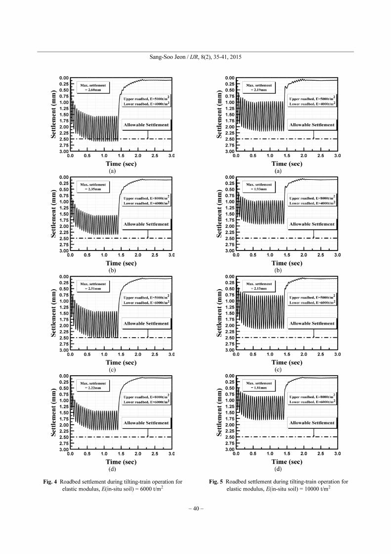
The parametric studies were carried out with respect to
the elastic moduli of upper roadbed, lower roadbed, and
in-situ soil of 5000 and 8000 t/m2, 4000 and 6000 t/m2,
and 6000 and 10000 t/m2, respectively. Figs. 4 and 5 show
the roadbed settlement with respect to the elasticity of
upper and lower roadbed and of in-situ soil. As expected,
the settlement exponentially increases as the elasticity of
roadbeds and in-situ soil decreases.
As recommended by the design criteria of the railway,
the soil reaction modulus, K30, of upper and lower road-
bed should be greater than 110 and 70 t/m2, respectively,
where the in-situ soil is stiff enough. However, it was
found that the maximum settlement was greater than the
allowable settlement of 2.5 mm when the elastic moduli of
in-situ soil, upper roadbed, and lower roadbed were 6000,
5000, and 4000 t/m2, respectively. Fig. 4(a) shows the
roadbed settlement. As the load was initially applied to the
roadbed surface, the immediate settlement was 1.87 mm
and the maximum settlements induced by the continuous
repetitive wheel loading was 2.60 mm. The maximum
roadbed settlements associated with ground conditions are
Pt
PRimax
PRomax
+
B L×-------------------------------=
PRimax
PRomax
H∗G
W t( ) A
2--- 1 2πftcos–( )×=
Fig. 3 Pressure distribution in the areas of ballast [11]
Table 8 Roadbed settlement with respect to ground conditions
In-situ soil
(t/m2)
Lower Roadbed
(t/m2)
Upper Roadbed
(t/m2)
Settlement
(mm)
6000
40005000 2.60
8000 2.35
60005000 2.51
8000 2.22
10000
40005000 2.19
8000 1.93
60005000 2.15
8000 1.81
− 40 −
Sang-Soo Jeon / IJR, 8(2), 35-41, 2015
Fig. 4 Roadbed settlement during tilting-train operation for
elastic modulus, E(in-situ soil) = 6000 t/m2
Fig. 5 Roadbed settlement during tilting-train operation for
elastic modulus, E(in-situ soil) = 10000 t/m2

Settlement and Bearing Capacity of Roadbed Subjected to Tilting-train Loading in Various Ground Conditions
− 41 −
summarized in Table 8. Therefore, the reinforcement of in-
situ soil is recommended to increase its stiffness.
7. Conclusions
Allowable speed was estimated with the typical values
of cants associated with the radius of curve, 800 m. The
allowable speed was estimated for the radius of curve of
800 m associated with the cant of 120 mm. The maxi-
mum settlement was greater than the allowable settlement
of 2.5 mm when the elastic moduli of in-situ soil, upper
roadbed, and lower roadbed were 6000, 5000, and 4000 t/m2,
respectively. Fig. 4(a) shows the roadbed settlement. As
the load was initially applied to the roadbed surface, the
immediate settlement was 1.87 mm and the maximum set-
tlements induced by the continuous repetitive wheel load-
ing was 2.60 mm. Since repetitive train and thermal
loadings resulting in softening of upper roadbed may
cause greater settlement than the allowable settlement, the
elastic modulus of upper roadbed greater than 5000 t/m2
should be maintained not to exceed the allowable settle-
ment.
References
1. Esveld, C. (2001). “Modern railway,” MRT-Productions,
pp.1-16.
2. Harris, N. R., Schmid, F., and Smith, R. A. (1998). “Intro-
duction: Theory of tilting train behavior,” Journal of Rail and
Rapid Transit, Vol. 212, No. 1, January, pp.1-5.
3. Degrande, G., Clouteau, D., Othman, R., Arnst, M., Chebli,
H., Klein, R., Chatterjee, P., and Janssens, B. (2006). “A
numerical model for ground-borne vibrations from under-
ground railway traffic based on a periodic finite element-
boundary element formulation,” Journal of Sound and Vibra-
tion, Vol. 293, No. 3-5, June, pp.645-666.
4. Ju, S. H., Liao, J. R., and Ye, Y. L. (2010). “Behavior of
ground vibrations induced by trains moving on embank-
ments with rail roughness,” Soil Dynamics and Earthquake
Engineering, Vol. 30, No. 11, November, pp.1237-1249.
5. Kouroussis, G., Verlinden, O., and Conti, C. (2010). “On the
interest of integrating vehicle dynamics for the ground prop-
agation of vibrations: The case of urban railway traffic,”
Vehicle System Dynamics, Vol. 48, No. 12, January,
pp.1553-1571.
6. Paolucci, R., Maffeis, A., Scandella, L., Stupazzini, M., and
Vanini, M. (2003). “Numerical prediction of low-frequency
ground vibrations induced by high-speed trains at Leds-
gaard, Sweden,” Soil Dynamics and Earthquake Engineer-
ing, Vol. 23, No. 6, August, pp.425-433.
7. Saussine, G., Cholet, C., Gautier, P. E., Dubois, F., Bohatier,
C., and Moreau, J. J., (2006). “Modelling ballast behavior
under dynamic loading. Part 1: A 2D polygonal discrete ele-
ment method approach,” Computer Methods in Applied
Mechanics and Engineering, Vol. 195, No. 19-22, April,
pp.2841-2859.
8. Wang, J., and Zeng, X., (2004). “Numerical simulations of
vibration attenuation of high-speed train foundations with
varied trackbed underlayment materials,” Journal of Vibra-
tion and Control, Vol. 10, No. 8, August, pp.1123-1136.
9. Itasca consulting group, Inc. (2002). “FLAC2D User man-
ual (Version 4.0),” Minneapolis: Itasca Consulting Group
Inc, pp. 1-4.
10. Korean National Railway (2001). “Design criteria for Rail-
road (Roadbed),” Korean National Railway, pp. 72-83.
11. Eum, K. Y., Koo, D. H., Yang, S. C., Yeo, I. H., Mun, H. S.,
Um, J. H., Sin, S. K., Kim, T. W., Kim, E., and Lee, H. S.
(2005). “Development of track system innovation technol-
ogy for speed-up conventional line,” Korea Railroad
Research Institute. 5th Report.
12. Seo, S. (2002). “Railway engineering,” Korea: Eul & Al
Press, pp.327-394.