service technical bulletin - jagrepair.comjagrepair.com/images/tsb/s-type/s303-14 v6_v8 engine...
TRANSCRIPT

Date of issue 09/02 Bulletin Number S303-14 Page 1 of 70
DATE S303-1409/02
SERVICE TECHNICAL BULLETINMIL Illuminated –
V6/V8 Engine Management Diagnosis –Flowcharts
2003 MY-ONS-TYPE
M45255-ON
MODEL
VIN
Issue:This bulletin provides diagnosis procedures for various components of the enginemanagement system.
ENGINE MANAGEMENT SYSTEM FLOWCHARTS – TABLE OF CONTENTSFlowchart TitleP-1 Air Leakage (pages 2 and 3).P-2 Accelerator Pedal Position Sensor (pages 4, 5, 6 and 7).P-3 Camshaft Position Sensor (pages 8, 9, and 10).P-3a Additional Information (Camshaft Position Sensor) (pages 11 and 12).P-4 Crankshaft Position Sensor (pages 13, 14, 15 and 16).P-4a Additional Information (Crankshaft Position Sensor) (page 17).P-5 Engine Coolant Temperature Sensor (pages 18, 19 and 20).P-6 Engine Fuel Temperature Sensor (pages 21, 22 and 23).P-6a Engine Fuel Temperature Sensor Characteristics (page 24).P-7 V8 NA/SC Exhaust Gas Recirculation Valve (pages 25, 26, 27, 28 and 29).P-8 Upstream and Downstream Oxygen Sensor (pages 30, 31, 32, 33 and 34).P-8a Additional Information (Upstream and Downstream Oxygen Sensors)
(page 35 and 36).P-9 V6/V8 NA Intake Air Temperature Sensor (pages 37, 38, 39 and 40).P-10 Injection Pressure Sensor (41, 42, 43, and 44).P-11 Knock Sensor (pages 45, 46 and 47).P-12 Mass Air Flow Sensor (pages 48, 49, 50, 51 and 52).P-13 Throttle Motor (pages 53, 54 and 55).P-14 V6/V8 NA Variable Valve Timing (pages 56, 57 and 58).P-15 Ignition Coil (pages 59, 60, 61, 61 and 63).P-15a Additional Information (Ignition Coil) (page 64).P-16 Throttle Position Sensor (pages 65, 66, 67 and 68).
Generic Connector Inspection (page 69).Generic Harness Check (page 70).

Air LeakageFlowchart P-1
Select the short term fuel trim (STFT) for banks 1 and 2,also select oxygen sensor upstream equivalence ratio for banks 1 and 2.
Visually check that all vacuum and breather pipes are correctlyfitted to the intake manifold and air cleaner outlet pipe.
It is possible that an air leakwill be heard with the enginerunning at idle, depending onthe severity of the leak.
A
Start the engine and run to normal operating temperature.Monitor the selected signals.
Use the Worldwide Diagnostic System (WDS) to interrogatethe Engine Control Module (ECM) for DiagnosticTrouble
Codes (DTC).
If the air leak is severeand the engine cannot
compensate for the leaka DTC will be logged.
Related DTCs:P0171 Fuel system toolean bank 1P0174 Fuel system toolean bank 2
The STFT values shouldfluctuate around 0% ± 7%.
The equivalence ratio shouldfluctuate around 1.0%.
If an air leak is present expectthe value to be between
1.05-1.25% at idle.
On the WDS, select thedatalogger tab.
Date of issue 09/02 z Bulletin Number S303-14 Page 2 of 70
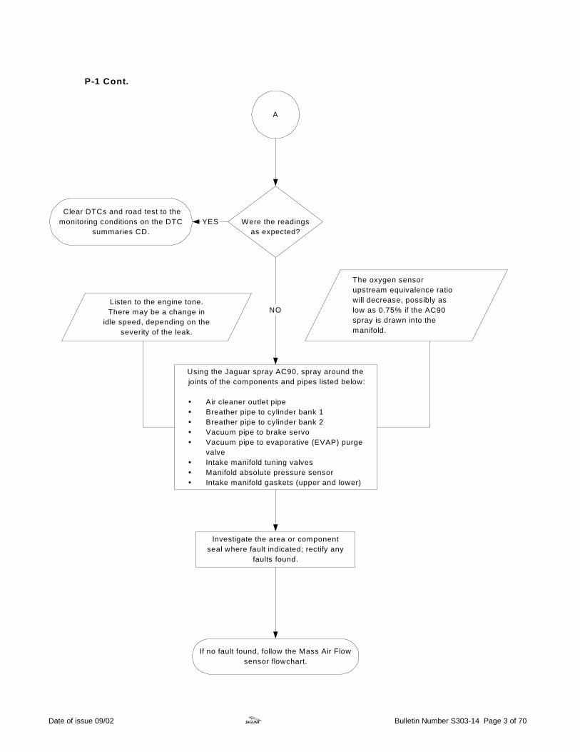
A
Investigate the area or componentseal where fault indicated; rectify any
faults found.
Using the Jaguar spray AC90, spray around the joints of the components and pipes listed below:
! Air cleaner outlet pipe! Breather pipe to cylinder bank 1! Breather pipe to cylinder bank 2! Vacuum pipe to brake servo! Vacuum pipe to evaporative (EVAP) purge
valve! Intake manifold tuning valves! Manifold absolute pressure sensor! Intake manifold gaskets (upper and lower)
Listen to the engine tone.There may be a change in
idle speed, depending on theseverity of the leak.
The oxygen sensorupstream equivalence ratiowill decrease, possibly aslow as 0.75% if the AC90spray is drawn into themanifold.
Were the readingsas expected?
NO
YES
If no fault found, follow the Mass Air Flowsensor flowchart.
Clear DTCs and road test to themonitoring conditions on the DTC
summaries CD.
P-1 Cont.
Date of issue 09/02 z Bulletin Number S303-14 Page 3 of 70

Accelerator Pedal Position Sensor Flowchart P-2
Related DTCs: P1122 APP sensor circuit 1 low input P1123 APP sensor circuit 1 high input P1215 APP sensor circuit 2 low input P1216 APP sensor circuit 2 high input P1344 APP sensor circuits 1 and 2 range/performance
Use the Worldwide Diagnostic System (WDS) to interrogatethe Engine Control Module (ECM) for DiagnosticTrouble
Codes (DTC).
Using WDS, select Datalogger,Engine Systems and then select pedal position sensor track 1 and track 2,
and pedal demand position sensor 2 voltage (central processor unit 2).
Were the readingsas expected?
ANOYES
Monitor the signals,Track 1 values:
Max = 3.39volts ± 0.3voltMin = 1.9volts ± 0.3volt
Track 2 values:Min = 0.73volts ± 0.3voltMax = 3.68volts ± 0.3volt
Accelerator Pedal Position Sensor (APP) faults areindicated via the Malfunction Indicator Lamp (MIL)
on the second trip.
Fluctuating the throttle pedalwill cause the values to
change within these definedtolerances.
Clear DTCs and road test to the monitoring conditions in the
DTC summaries CD.
Date of issue 09/02 z Bulletin Number S303-14 Page 4 of 70
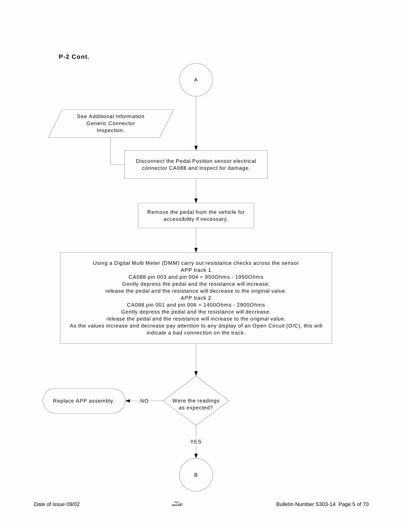
A
Using a Digital Multi Meter (DMM) carry out resistance checks across the sensorAPP track 1
CA088 pin 003 and pin 004 = 950Ohms - 1950OhmsGently depress the pedal and the resistance will increase,
release the pedal and the resistance will decrease to the original value.APP track 2
CA088 pin 001 and pin 006 = 1400Ohms - 2900OhmsGently depress the pedal and the resistance will decrease,
release the pedal and the resistance will increase to the original value.As the values increase and decrease pay attention to any display of an Open Circuit (O/C), this will
indicate a bad connection on the track.
Were the readingsas expected?
NO
Disconnect the Pedal Position sensor electricalconnector CA088 and inspect for damage.
See Additional InformationGeneric Connector
Inspection.
B
YES
Remove the pedal from the vehicle foraccessibility if necessary.
Replace APP assembly.
P-2 Cont.
Date of issue 09/02 z Bulletin Number S303-14 Page 5 of 70

With the ignition 'ON' and using a DMM,check for 5 volt supply at pin 002 and pin 005 of APP
electrical connector CA088.
Was the reading asexpected?
Carry out Generic Harness Check between the APP sensor electricalconnector CA088 and the ECM electrical connector PI001
CA088 pin 005 - PI001 pin 013 (yellow wire)CA088 pin 002 - PI001 pin 012 (orange and yellow wire) .
Ensure the ignition is switched 'OFF' anddisconnect ECM electrical connector PI001.
B
NO
YES
See Additional InformationGeneric Harness Check.
See Additional InformationGeneric Connector
Inspection.
Was a fault foundand rectified?
END YES Contact Technical Hotline for further assistance.NO
C
Refer to S-TYPEElectrical Guide on JTIS.
If the 5 volt supply has beenlost from the ECM, suspect
additional sensor fault codesto be logged.
Carry out a Generic Connector Inspection onECM electrical connector PI001.
P-2 Cont.
Date of issue 09/02 z Bulletin Number S303-14 Page 6 of 70

C
Carry out a Generic Harness Check between the APP Sensorelectrical connector and the ECM electrical connector.
APP circuit 1 CA088 pin 004 - PI001 pin 102 CA088 pin 003 - PI001 pin 020
APP circuit 2 CA088 pin 001 - PI001 pin 103 CA088 pin 006 - PI001 pin 019
Was a fault foundand rectified?
END YES
See Additional InformationGeneric Harness Check.
Contact TechnicalHotline for further assistance.
NO
See Additional InformationGeneric Connector
Inspection.
Check the harness for damage where possiblebefore disconnecting the ECM.
Ensure the ignition is switched 'OFF'.Disconnect ECM electrical connector PI001,
and check for any damage.
P-2 Cont.
Date of issue 09/02 z Bulletin Number S303-14 Page 7 of 70

Camshaft Position SensorFlowchart P-3
Related DTCs:P0340 Camshaft sensorside 1 malfunctionP0341 Camshaft sensorside 1 range/performanceP1340 Camshaft sensorside 2 malfunctionP1341 Camshaft sensorside 2 range/performance
Disconnect the relevant CMP sensor electrical connectorand carry out a Generic Connector Inspection.
See Additional InformationGeneric Connector
Inspection.
A
Camshaft Position (CMP) sensor faults are indicatedvia the Malfunction Indicator Lamp (MIL)
(only on the second trip).
The sensors on V8 enginesare fitted with a flylead.
Use the Worldwide Diagnostic System (WDS) to interrogatethe Engine Control Module (ECM) for DiagnosticTrouble
Codes (DTC).
Date of issue 09/02 z Bulletin Number S303-14 Page 8 of 70
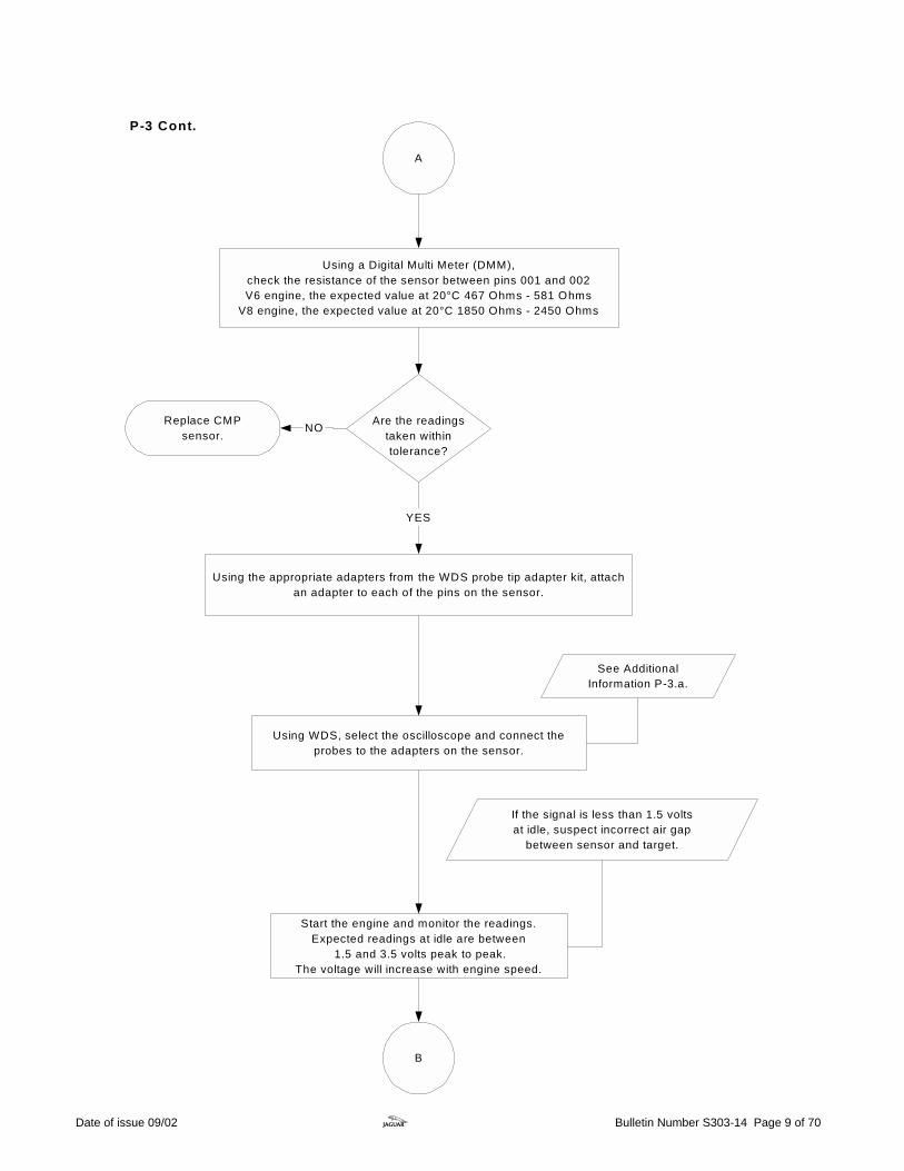
B
NO Are the readingstaken withintolerance?
A
YES
Using the appropriate adapters from the WDS probe tip adapter kit, attachan adapter to each of the pins on the sensor.
Using a Digital Multi Meter (DMM),check the resistance of the sensor between pins 001 and 002V6 engine, the expected value at 20°C 467 Ohms - 581 Ohms
V8 engine, the expected value at 20°C 1850 Ohms - 2450 Ohms
Replace CMPsensor.
See AdditionalInformation P-3.a.
Start the engine and monitor the readings.Expected readings at idle are between
1.5 and 3.5 volts peak to peak.The voltage will increase with engine speed.
If the signal is less than 1.5 voltsat idle, suspect incorrect air gap
between sensor and target.
Using WDS, select the oscilloscope and connect theprobes to the adapters on the sensor.
P-3 Cont.
Date of issue 09/02 z Bulletin Number S303-14 Page 9 of 70

Was a fault foundand rectified?
END NOYES
B
Carry out a Generic Harness check between the relevant CMP sensor engineharness electrical connector and the ECM electrical connector PI001.
V6 CMP sensor 1 PI057 pin 001 - PI001 pin 094 (Yellow wire)
PI057 pin 002 - PI001 pin 095 (Red wire)V6 CMP sensor 2
PI056 pin 001 - PI001 pin 068 (Brown wire)PI056 pin 002 - PI001 pin 069 (Green wire)
V8 CMP sensor 1PI023 pin 001 - PI001 pin 095 (Red wire)
PI023 pin 002 - PI001 pin 094 (Yellow wire)V8 CMP sensor 2
PI022 pin 001 - PI001 pin 068 (Brown wire)PI022 pin 002 - PI001 pin 069 (Green wire)
Are the readingsas expected?
Contact Technical Hotline forfurther assistance.
NO
YES
Contact Technical Hotline forfurther assistance.
Ensure the ignition is switched 'OFF' .Disconnect ECM electrical connector PI001.
Inspect CMP sensor and timing cover forsigns of damage and ensure the sensor is
fitted correctly.
P-3 Cont.
Where possible check the harness fordamage before disconnecting the ECM.
Date of issue 09/02 z Bulletin Number S303-14 Page 10 of 70

Additional Information P-3a
Oscilloscope set up. 1 Configuration sub tab.
Channel 1 Select: Red probe and black probe-Differential.
2 Channel calculation sub tab. Select: Maximum voltage.
3 Main oscilloscope display sub tab. Y-axis select: Scale set to 1 volt/div. X-axis select: Scale set to 10 ms/div.
4 Select: Full screen.
Illustration 1 Trace of the camshaft position sensor at idle
Date of issue 09/02 z Bulletin Number S303-14 Page 11 of 70

P-3.a Cont.
Illustration 2 Trace of camshaft position sensor at 2000 rpm
Date of issue 09/02 z Bulletin Number S303-14 Page 12 of 70

Crankshaft Position SensorFlowchart P-4
Crankshaft Position (CKP) sensor faults areindicated via the Malfunction Indicator Lamp (MIL)
(only on second trip).
Note: The vehicle w ill run ifa fault exists in the CKPsensor or the associatedcircuit, but the customer
will experience longcranking times.
Related DTCs:P0335 Sensor malfunctionP0336 Sensor circuitrange/performance.
Use the Worldwide Diagnostic System (WDS) tointerrogate the Engine Control Module (ECM)
for DiagnosticTrouble Codes (DTC).
A
Ensure the ignition is switched 'OFF'.
Disconnect the CKP sensor electrical connector andperform a Generic Connector Inspection.
V8 engines - PI021V6 engines - PI055
See Additional InformationGeneric Connector
Inspection.
Date of issue 09/02 z Bulletin Number S303-14 Page 13 of 70

Remove the CKP sensor from the vehicle andcheck for any signs of damage.
Inspect for debris andensure CKP sensor is clean.
Was a fault foundand rectified?
Check CKP sensor mounting in the engine blockis clean of any debris and is not damaged.
YESEND
B
NO
A
Refer to JTIS Section 303-14A/B, SRO 18.30.12 forremoval and installation
instructions.
NO
Use a Digital Multi Meter (DMM), to check the resistance of the CKP sensor.
V6 engine, expected value at 20°C = 305 Ohms - 395 Ohms
V8 engine, expected value at 20°C = 940 Ohms - 1350 Ohms
YES
Renew CKP sensor. Were the readingsas expected?
P-4 Cont.
Date of issue 09/02 z Bulletin Number S303-14 Page 14 of 70

B
Start the engine and monitor the readings.Expected reading at idle, between
4 - 8 volts peak to peak.The voltage will increase with engine speed.
Were the readingsas expected?
YES NOContact Technical
Hotline for further assistance.
See AdditionalInformation
P-4.a.
Caution: Keep probes /equipm ent clear of rotating
pulleys and drive belts.
Using the adapters (number JT-034) from the WDS probe tip adapter kit,attach an adapter to each of the pins on the CKP sensor .
Install the CKP sensor.
C
See AdditionalInformation P-4.a.
CKP sensorretaining bolt
tightening torque 7 -10 Nm.
P-4 Cont.
Using the WDS, select the oscilloscope and connect the red andblack probes to the adapters on the sensor.
Date of issue 09/02 z Bulletin Number S303-14 Page 15 of 70

C
Was a fault foundand rectified?
END
Contact TechnicalHotline for further assistance.
NO
YES
Carry out a Generic Harness Check between CKP sensorelectrical connector and the ECM electrical connector PI001.
V6 CKP sensorPI055 pin 001 - PI001 pin 037 (Black wire)
PI055 pin 002 - PI001 pin 036 (Orange wire)
V8 CKP sensorPI021 pin 001 - PI001 pin 037 (Black wire)
PI021 pin 002 - PI001 pin 036 (Orange wire)
See Additional InformationGeneric Harness Check.
Refer to S-TYPEElectrical Guide.
See Additional InformationGeneric Connector
Inspection.
Ensure the ignition is switched 'OFF'.Disconnect ECM electrical connector PI001,
and check for any damage.
If possible check the harness for damagebefore disconnecting the ECM.
P-4 Cont.
Date of issue 09/02 z Bulletin Number S303-14 Page 16 of 70

Additional Information P-4.a
Oscilloscope set up. 1 Configuration sub tab.
Channel 1 Select: Red probe and black probe - Differential.
2 Channel calculation sub tab. Select: Maximum voltage.
3 Main oscilloscope display sub tab. Y-axis select: Scale set to 1 V/div. X-axis select: Scale set to 10 ms/div.
4 Select: Full screen.
WDS
1Y
x
A B
T
Illustration 3 Trace of the crankshaft position sensor at idle
Date of issue 09/02 z Bulletin Number S303-14 Page 17 of 70

Engine Coolant Temperature SensorFlowchart P-5
Use the Worldwide Diagnostic System (WDS) tointerrogate the Engine Control Module (ECM) for
DiagnosticTrouble Codes (DTC).
Related DTCs:P0116 Sensor circuit range/performanceP0117 Sensor circuit highvoltageP0118 Sensor circuit lowvoltageP0125 Poor sensor response
A
Ensure the coolant level is correct, and no leaks areapparent before carrying out any diagnostics.
Were the readingsas expected?
At normal operatingtemperature theengine coolanttemperature is
maintained between85-95 °C.
NO
Engine Coolant Temperature (ECT) Sensor faults areindicated via the Malfunction Indicator Lamp (MIL)
(only on second trip).
Clear DTCs and road test to themonitoring conditions on the DTC
summaries CD.
YES
Using WDS select the datalogger tab.Select engine systems and then select the engine
coolant temperature sensor.Monitor the readings to verify the operation of the
ECT sensor.
Date of issue 09/02 z Bulletin Number S303-14 Page 18 of 70

B
A
END
Run engine up to normaloperating temperature and
ensure cooling fansoperate at 95 °C.
See Additional InformationGeneric Connector
Inspection.
Check the resistance of the sensor incomparison to the engine temperature.
Expected readings-10 °C = 9.16 k Ohms
20 °C = 2.45 ± 0.14 k Ohms40 °C = 1.15 k Ohms
60 °C = 0.584 k Ohms80 °C = 0.31 ± 0.008 k Ohms
Was a fault found?
Ensure that the sensor is free fromcontamination
and is not damaged,(i.e. cracked or corroded).
Was a fault found?
Reinstall ECT sensor(torque to 19.6 Nm).
NO
Disconnect the ECT sensor electrical connectorPI025.
Carry out a Generic Connector Inspection.
NO
Renew ECT sensor.
Replace ECT sensor.
Run engine up to normaloperating temperature and
ensure cooling fansoperate at 95 °C.
END
YES
YES
P-5 Cont.
Date of issue 09/02 z Bulletin Number S303-14 Page 19 of 70

Carry out a Generic Harness Check between ECT sensorelectrical connector and the ECM electrical connector.PI025 pin 002 - PI001 pin 070 (Blue and yellow wire)PI025 pin 001 - PI001 pin 019 (Black and green wire)
Ensure the ignition is switched 'OFF' anddisconnect ECM electrical connector PI001.
See Additional InformationGeneric Connector
Inspection.
See Additional InformationGeneric Harness Check.
Was a fault foundand rectified?
END YES
Inspect ECM electrical connector and pins for damage.
B
Contact Technical Hotline for further assistance.
Refer to S-TYPEElectrical Guide.
Where possible check the harness for damagebefore disconnecting the ECM.
NO
P-5 Cont.
Date of issue 09/02 z Bulletin Number S303-14 Page 20 of 70
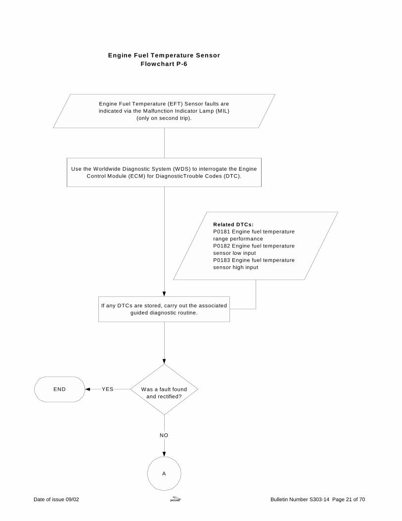
Engine Fuel Temperature (EFT) Sensor faults areindicated via the Malfunction Indicator Lamp (MIL)
(only on second trip).
Engine Fuel Temperature SensorFlowchart P-6
Related DTCs:P0181 Engine fuel temperaturerange performanceP0182 Engine fuel temperaturesensor low inputP0183 Engine fuel temperaturesensor high input
Use the Worldwide Diagnostic System (WDS) to interrogate the EngineControl Module (ECM) for DiagnosticTrouble Codes (DTC).
Was a fault foundand rectified?
YES
NO
END
A
If any DTCs are stored, carry out the associatedguided diagnostic routine.
Date of issue 09/02 z Bulletin Number S303-14 Page 21 of 70

A
Were the readingsas expected?
YES
NO
Use a Digital Multi Meter (DMM) to check the resistance of the sensor.
See Additional InformationGeneric Connector
Inspection.
Disconnect the EFT sensor electrical connector and carryout a Generic Connector Inspection.
V6 engines - IL009V8 engines - PI027
BReplace EFT sensor. NO YESWere the readingsas expected?
Monitor the readings with the engine running.The WDS will display the values as a voltage.
See Additional Information P-6.a.
See Additional InformationP-6.a.
A change in temperatureshould be apparent as the
engine temperatureincreases.
Clear DTCs and road test to themonitoring conditions on the DTC
summaries CD.
P-6 Cont.
On the WDS, select datalogger, engine systems and then selectfuel rail temperature sensor.
Date of issue 09/02 z Bulletin Number S303-14 Page 22 of 70
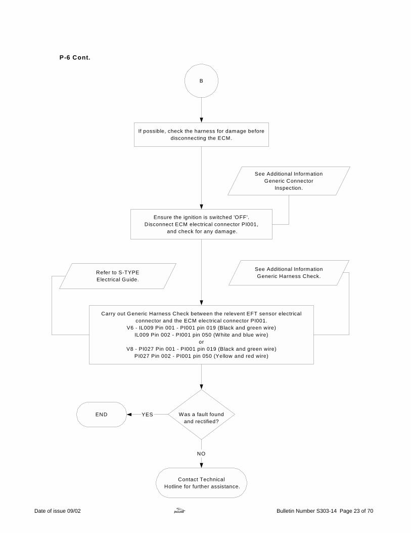
B
Carry out Generic Harness Check between the relevent EFT sensor electricalconnector and the ECM electrical connector PI001.
V6 - IL009 Pin 001 - PI001 pin 019 (Black and green wire)IL009 Pin 002 - PI001 pin 050 (White and blue wire)
orV8 - PI027 Pin 001 - PI001 pin 019 (Black and green wire)
PI027 Pin 002 - PI001 pin 050 (Yellow and red wire)
See Additional InformationGeneric Harness Check.
Was a fault foundand rectified?
END YES
Contact Technical Hotline for further assistance.
NO
Refer to S-TYPEElectrical Guide.
See Additional InformationGeneric Connector
Inspection.
If possible, check the harness for damage beforedisconnecting the ECM.
Ensure the ignition is switched 'OFF'.Disconnect ECM electrical connector PI001,
and check for any damage.
P-6 Cont.
Date of issue 09/02 z Bulletin Number S303-14 Page 23 of 70

Additional Information P-6.a
Engine Fuel Temperature Sensor Characteristics.
Temperature.
Nominal resistance
Using DMM.
WDS Datalogger voltage display.
-10°C (14°F)
160.3 k-ohms ± 8.3 k-ohms
4.15 volts ± 0.04 v
10°C (50°F)
58.9 k-ohms ± 2.9 k-ohms
3.52 volts ± 0.06 v
20°C (68°F)
37.3 k-ohms ± 2.1 k-ohms
3.09 volts ± 0.07 v
30°C (86°F)
24.2 k-ohms ± 1.4 k-ohms
2.62 volts ± 0.07 v
40°C (104°F)
16.1 k-ohms ± 0.9 k-ohms
s
2.15 volts ± 0.08 v
Abbreviations: WDS - Worldwide Diagnostic System. DMM - Digital Multi Meter. Note: When testing the Engine Fuel Temperature sensor, if the vehicle is cold (approximately workshop temperature 20°C) it is possible to invoke a temperature change by rubbing the rail where the sensor is situated, this will increase the temperature and decrease the resistance.
WARNING: Parts may be hot.
Date of issue 09/02 z Bulletin Number S303-14 Page 24 of 70

B
V8 NA & SC Exhaust GasRecirculation Valve Flowchart P-7
Was the signal asexpected?
YES NOA
Use the Worldwide Diagnostic System (WDS) to interrogate theEngine Control Module (ECM) for DiagnosticTrouble Codes (DTC)
Related DTCs:P0400 EGR system flowmalfunctionP0405 EGR systemvalve circuit low inputP0406 EGR systemvalve circuit high input
Check to see if the EGR carries out its self cleaningroutine when the ignition is switched 'ON'
The self clean will generatea light clicking noise for a
few seconds.This will confirm electrical
operation only.
Using the WDS, select engine system from the content modelscreen and then the datalogger tab.
Select exhaust gas recirculation and monitor the signal.
Moinitor the signal as the engine reaches fulloperating temperature
Expect 25 ± 10 steps at a steady 50 mph.
Date of issue 09/02 z Bulletin Number S303-14 Page 25 of 70
Was a fault found andrectified?
YES
A
NO
Contact Technical Hotline for further assistance
END
Ensure the EGR valve is correctly installed.Visually check the exhaust valve tube and vacuum
pipe (if fitted) for correct installation.
Exhaust noise may beheard if the exhaust valvetube is not fitted correctly
If the valve is stuck closed or arestriction is present no changein flow through the EGR will be
monitored and P0400 will belogged.
Check to see if the valve is blocked withexcessive carbon build up.
Carry out the Exhaust Gas Recirculation Monitior drivecycle found on the DTC summaries CD.
Use WDS to clear DTCs.
If the valve is stuckopen it would cause
a rough idle.
P-7 Cont.
Date of issue 09/02 z Bulletin Number S303-14 Page 26 of 70

C
With the ignition 'ON' check for battery voltage at fuse 37 in the Front Power Distribution Box (FPDB)
(if no voltage found investigate EMS relay (R5) in the FPDB).
Disconnect the EGR electrical connector PI015and carry out a Generic Connector Inspection.
See Additional InformationGeneric Connector Inspection.
Using a Digital Multi Meter (DMM)check for battery voltage at EGR electrical connector
PI015 pin 002 and pin 005.
Using a DMM, check the EGR valve resistance,Ensure the readings are taken at 20 - 30°Cbetween pin 004 - pin 006 = 55 - 65 Ohmsbetween pin 004 - pin 005 = 25 - 35 Ohmsbetween pin 005 - pin 006 = 25 - 35 Ohmsbetween pin 001 - pin 003 = 55 - 65 Ohmsbetween pin 001 - pin 002 = 25 - 35 Ohmsbetween pin 002 - pin 003 = 25 - 35 Ohms
YES
Were the readingsas expected?
NOYES Replace the EGR valve.
Was battery voltagepresent at both
pins?
B
DNO
Refer to S-TYPEElectrical Guide.
P-7 Cont.
Date of issue 09/02 z Bulletin Number S303-14 Page 27 of 70

C
Carry out Generic Harness Check between EGR electricalconnector PI015 and the ECM electrical connector PI001
PI015 pin 004 - PI001 pin 057 (Yellow and blue wire)PI015 pin 001 - PI001 pin 058 (Yellow and green wire)
PI015 pin 006 - PI001 pin 059 (Yellow and red wire)PI015 pin 003 - PI001 pin 060 (Yellow and blue wire)
See Additional InformationGeneric Harness Check.
See Additional InformationGeneric Connector
Inspection.
Was a fault foundand rectified?
Contact Technical Hotline for further assistance.
NO
END YES
Ensure the ignition is switched 'OFF'.Disconnect ECM electrical connector PI001,
and check for any damage
Check the harness for damage where possiblebefore disconnecting the ECM.
P-7 Cont.
Date of issue 09/02 z Bulletin Number S303-14 Page 28 of 70

D
Carry out Generic Harness Check betweenEGR electrical connector PI015 pin 002 and pin
005 and fuse 37 in the FPDB.
Refer to S-TYPEElectrical Guide.
See Additional InformationGeneric Harness Check.
Was a fault foundand rectified?
YESEND
NO
Contact Technical Hotline for further assistance.
Check fuse 37 in the FPDBIf fuse blown, suspect short circuit low.
Check the fuse rating.(15 Amp).
If fuse is blown the fault maybe on a related circuit due to
the splice in the harness.Refer to the S-TYPE
Electrical Guide.
P-7 Cont.
Date of issue 09/02 z Bulletin Number S303-14 Page 29 of 70

Check for air leaks at sensorsNote: Ensure sensors are tightened to the correct torque.
Check for damage to the electrical connectionsand harness.
YES
NO
Upstream and Downstream Oxygen Sensor Flowchart P-8
Check for correct orientation of oxygen sensors.
A
See AdditionalInformation
P-8.a.
See Additional Information.Generic Connector
Inspection.
Was a fault foundand rectified?
See Additional InformationP-8.a.
Carry out visual check of exhaust system and examineexhaust for cracks between manifold and catalytic
converter.
Upstream and downstream oxygen sensor faults areindicated via the Malfunction Indicator Lamp (MIL)
(only on the second trip).
Clear DTCs and road testto the oxygen sensor monitor
drive cycle on the DTC summariesCD.
See AdditionalInformation
P-8.a.
Date of issue 09/02 z Bulletin Number S303-14 Page 30 of 70
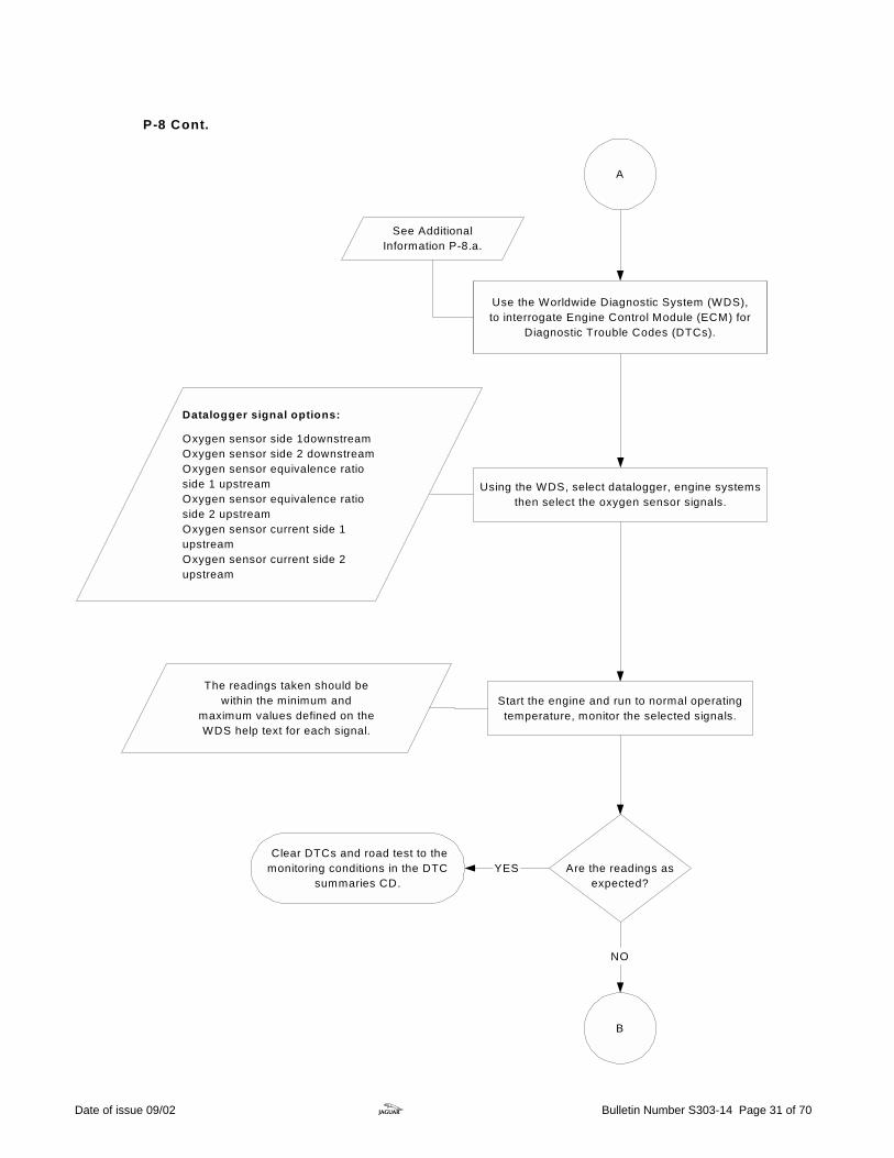
B
Use the Worldwide Diagnostic System (WDS),to interrogate Engine Control Module (ECM) for
Diagnostic Trouble Codes (DTCs).
Datalogger signal options:
Oxygen sensor side 1downstreamOxygen sensor side 2 downstreamOxygen sensor equivalence ratioside 1 upstreamOxygen sensor equivalence ratioside 2 upstreamOxygen sensor current side 1upstreamOxygen sensor current side 2upstream
Are the readings asexpected?
NO
YES
A
See AdditionalInformation P-8.a.
Clear DTCs and road test to themonitoring conditions in the DTC
summaries CD.
The readings taken should bewithin the minimum and
maximum values defined on theWDS help text for each signal.
P-8 Cont.
Using the WDS, select datalogger, engine systemsthen select the oxygen sensor signals.
Start the engine and run to normal operatingtemperature, monitor the selected signals.
Date of issue 09/02 z Bulletin Number S303-14 Page 31 of 70
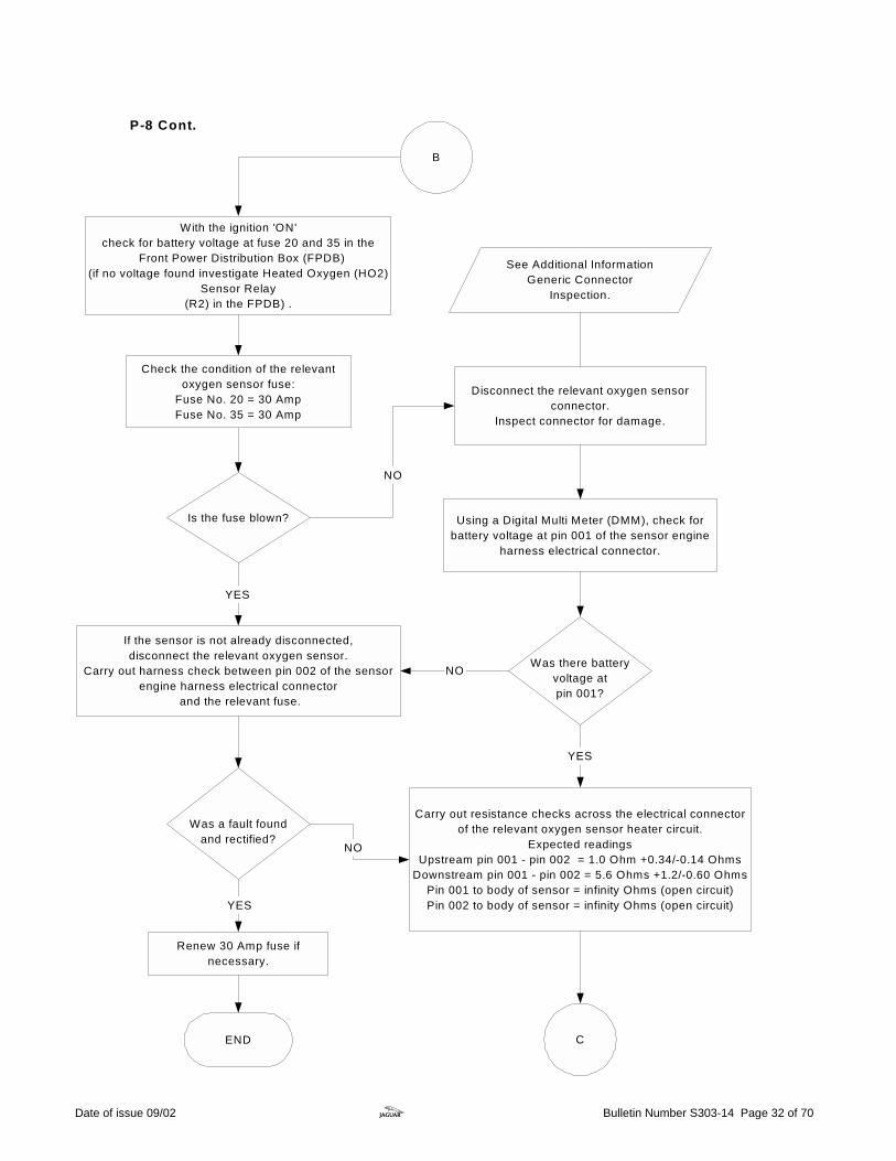
Is the fuse blown?
If the sensor is not already disconnected,disconnect the relevant oxygen sensor.
Carry out harness check between pin 002 of the sensorengine harness electrical connector
and the relevant fuse.
YES
YES
With the ignition 'ON'check for battery voltage at fuse 20 and 35 in the
Front Power Distribution Box (FPDB)(if no voltage found investigate Heated Oxygen (HO2)
Sensor Relay(R2) in the FPDB) .
NO
Disconnect the relevant oxygen sensorconnector.
Inspect connector for damage.
NO
Using a Digital Multi Meter (DMM), check forbattery voltage at pin 001 of the sensor engine
harness electrical connector.
Was there batteryvoltage atpin 001?
Carry out resistance checks across the electrical connectorof the relevant oxygen sensor heater circuit.
Expected readingsUpstream pin 001 - pin 002 = 1.0 Ohm +0.34/-0.14 Ohms
Downstream pin 001 - pin 002 = 5.6 Ohms +1.2/-0.60 OhmsPin 001 to body of sensor = infinity Ohms (open circuit)Pin 002 to body of sensor = infinity Ohms (open circuit)
NO
YES
Was a fault foundand rectified?
B
CEND
See Additional InformationGeneric Connector
Inspection.
Check the condition of the relevantoxygen sensor fuse:
Fuse No. 20 = 30 AmpFuse No. 35 = 30 Amp
Renew 30 Amp fuse ifnecessary.
P-8 Cont.
Date of issue 09/02 z Bulletin Number S303-14 Page 32 of 70
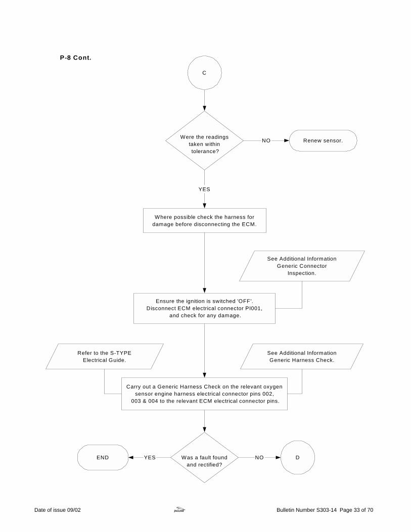
Carry out a Generic Harness Check on the relevant oxygensensor engine harness electrical connector pins 002,
003 & 004 to the relevant ECM electrical connector pins.
Were the readingstaken within tolerance?
NO
YES
YES NOWas a fault foundand rectified?
C
Renew sensor.
END
See Additional InformationGeneric Harness Check.
Refer to the S-TYPEElectrical Guide.
See Additional InformationGeneric Connector
Inspection.
Ensure the ignition is switched 'OFF'.Disconnect ECM electrical connector PI001,
and check for any damage.
Where possible check the harness fordamage before disconnecting the ECM.
D
P-8 Cont.
Date of issue 09/02 z Bulletin Number S303-14 Page 33 of 70
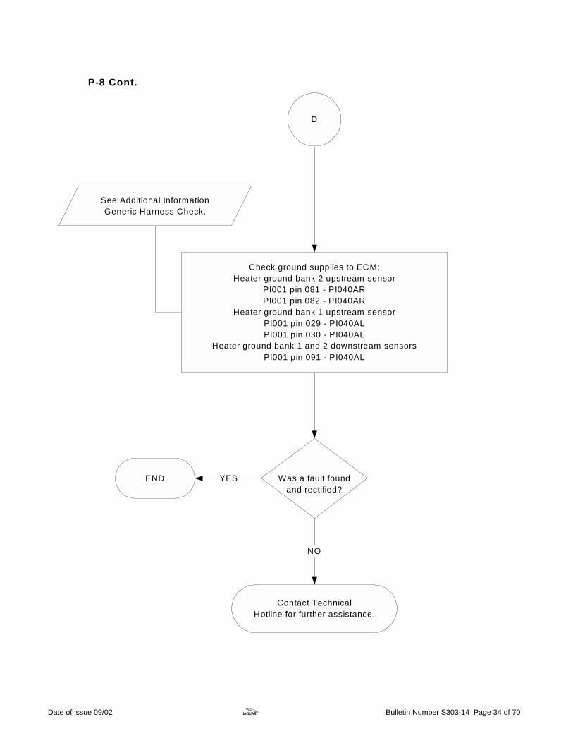
Contact TechnicalHotline for further assistance.
D
Check ground supplies to ECM:Heater ground bank 2 upstream sensor
PI001 pin 081 - PI040ARPI001 pin 082 - PI040AR
Heater ground bank 1 upstream sensorPI001 pin 029 - PI040ALPI001 pin 030 - PI040AL
Heater ground bank 1 and 2 downstream sensorsPI001 pin 091 - PI040AL
YES
NO
Was a fault foundand rectified?
END
See Additional InformationGeneric Harness Check.
P-8 Cont.
Date of issue 09/02 z Bulletin Number S303-14 Page 34 of 70

Additional Information P-8.a
Subject - Upstream and downstream oxygen Sensors.
Checks.
• The upstream sensor is designated UHEGO and has a gray connector. • The downstream sensor is designated HEGO and has a black connector. • To ensure that the sensors are fitted correctly, the upstream sensor is situated directly
above the catalytic converter (Pre- catalytic converter), and the downstream sensor is at the center of the catalytic converter.
• If the sensors are fitted vice versa this will cause catalytic converter monitor diagnostic trouble codes P0420 and P0430 to be logged.
• If the catalytic converter monitor DTCs are logged (P0420/P0430) and the orientation of the sensors is correct, then suspect catalytic converter failure. Remove the catalytic converter and visually check the honeycomb layout.
• Air leaks are possible at the connection of the sensor to the exhaust. Ensure the sensors are tightened to the correct torque.
• Problems may occur due to air leaks within the exhaust system. • Carry out visual checks for cracks and leaks from the manifold down to the catalytic
converter. • Listen for the exhaust vapor escaping when cold, as it may not be noticeable as the
exhaust warms and expands.
Cautions.
Removal. (Always refer to JTIS)
Ensure the connector on the fly lead is disconnected before removal. Failure to do this may cause the wires to twist and damage or pull out of the sensor.
Installation. (Always refer to JTIS)
Over tightening may cause damage to the element within the sensor. Ensure when fitting the sensor the correct tightening torque is used. (Torque setting for both sensors 40 Nm +/- 7.2 Nm.) Ensure the fly lead is routed correctly and is not taut, as this may cause damage with engine movement.
Date of issue 09/02 z Bulletin Number S303-14 Page 35 of 70

P-8.a Cont.
Additional Information
Upstream oxygen sensor Diagnostic Trouble Codes
Downstream oxygen sensor Diagnostic Trouble Codes
DTC Description
DTC
Description
P0031 P0032 P0051 P0052 P0131 P0132 P0133 P0151 P0152 P0153 P1646 P1647
Heater control circuit low A Heater control circuit high A Heater control circuit low B Heater control circuit high B Circuit low voltage A Circuit high voltage A Circuit slow response 1A Circuit low voltage B Circuit high voltage B Circuit slow response 1B Control module open/shorted A Control module open/shorted B
P0037 P0057 P0038 P0058 P0137 P0157 P0138 P0158 P0140 P0160
Heater control circuit low A Heater control circuit low B Heater control circuit high A Heater control circuit high B Circuit low voltage A Circuit low voltage B Circuit high voltage A Circuit high voltage B Circuit no activity A Circuit no activity B
Refer to the DTC Summaries CD-ROM for further information.
Date of issue 09/02 z Bulletin Number S303-14 Page 36 of 70

Intake Air Temperature (IAT) sensor faults areindicated via the Malfunction Indicator Lamp (MIL)
(only on second trip).
V6/V8 N/A Intake Air TemperatureSensor Flowchart P-9
Related DTCs:P0096 Intake air temperaturerange performance.P0097 Intake air temperaturesensor low input.P0098 Intake air temperaturesensor high input.
Use the Worldwide Diagnostic System (WDS)to interrogate the Engine Control Module (ECM)
for Diagnostic Trouble Codes (DTC).
A
The IAT sensor is anintegrated part of the MassAir Flow (MAF) sensor.
NOWere the readingsas expected?
YES
Monitor the selected signal with the enginerunning.
A slight change intemperature should be
apparent if the engine speedis increased.
Clear DTCs and road test to the monitoring conditions in the DTC summaries CD-ROM.
Using WDS, select datalogger, engine systems then selectintake air temperature.
Date of issue 09/02 z Bulletin Number S303-14 Page 37 of 70

A
Using a Digital Multi Meter (DMM) carry out resistancechecks across the IAT sensor between pins 004 and 005
Expected readings: -20°C = 16.0 kOhms ± 2.4 kOhms10°C = 4.0 kOhms ± 1.00 kOhms
20°C = 2.45 kOhms ± 0.24 kOhms30°C = 1.55 kOhms ± 0.25 kOhms
60°C = 0.58 kOhms ± 0.087 kOhms
See Additional InformationGeneric Connector
Inspection.
Disconnect IAT sensor electrical connector PI014and carry out Generic Connector Inspection.
Use a thermometer tocompare the air
temperature against thereading taken.
Removing the sensor fromthe engine and lightly
blowing on the sensor willalter the reading.
Renew MAF sensor.NOWere the readingsas expected?
Using a DMM check for battery voltage at pin 001of elctrical connector PI014.
Switch the ignition 'ON'.
Was battery voltagepresent?
NOYES DC
P-9 Cont.
Date of issue 09/02 z Bulletin Number S303-14 Page 38 of 70

C
Carry out Generic Harness Check between IAT electricalconnector PI014 and the ECM electrical connector PI001.
PI014 Pin 004 - PI001 pin 071 (Blue wire).PI014 Pin 005 - PI001 pins 019 (Black and green wire).
See AdditionalInformation
Generic Harness Check.
Was a fault foundand rectified?
END YES
Contact Technical Hotline for further assistance.
NO
See Additional InformationGeneric Connector
Inspection.
Where possible check the harness for damagebefore disconnecting the ECM.
Ensure the ignition is switched 'OFF'.Disconnect ECM electrical connector PI001,
and check for any damage.
P-9 Cont.
Date of issue 09/02 z Bulletin Number S303-14 Page 39 of 70
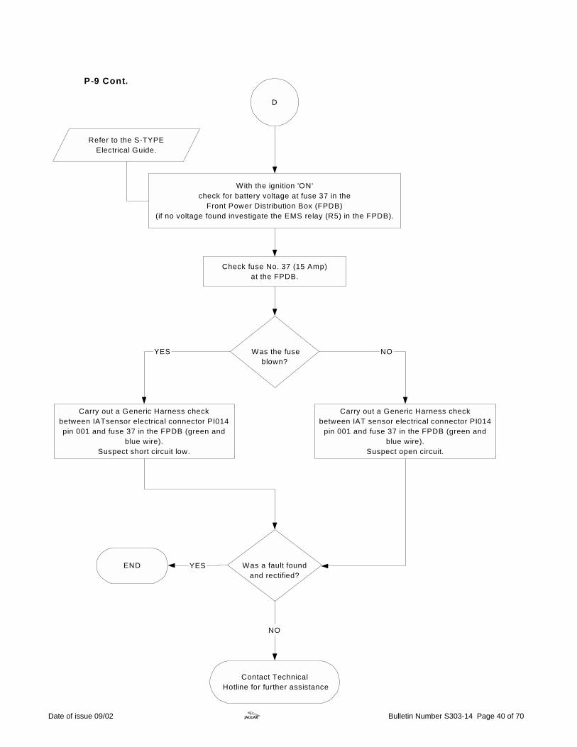
D
Was the fuseblown?
NO
Carry out a Generic Harness checkbetween IATsensor electrical connector PI014pin 001 and fuse 37 in the FPDB (green and
blue wire).Suspect short circuit low.
YES
Was a fault foundand rectified?
YES
Check fuse No. 37 (15 Amp)at the FPDB.
Contact Technical Hotline for further assistance
NO
Carry out a Generic Harness checkbetween IAT sensor electrical connector PI014
pin 001 and fuse 37 in the FPDB (green andblue wire).
Suspect open circuit.
END
With the ignition 'ON'check for battery voltage at fuse 37 in the
Front Power Distribution Box (FPDB)(if no voltage found investigate the EMS relay (R5) in the FPDB).
Refer to the S-TYPEElectrical Guide.
P-9 Cont.
Date of issue 09/02 z Bulletin Number S303-14 Page 40 of 70
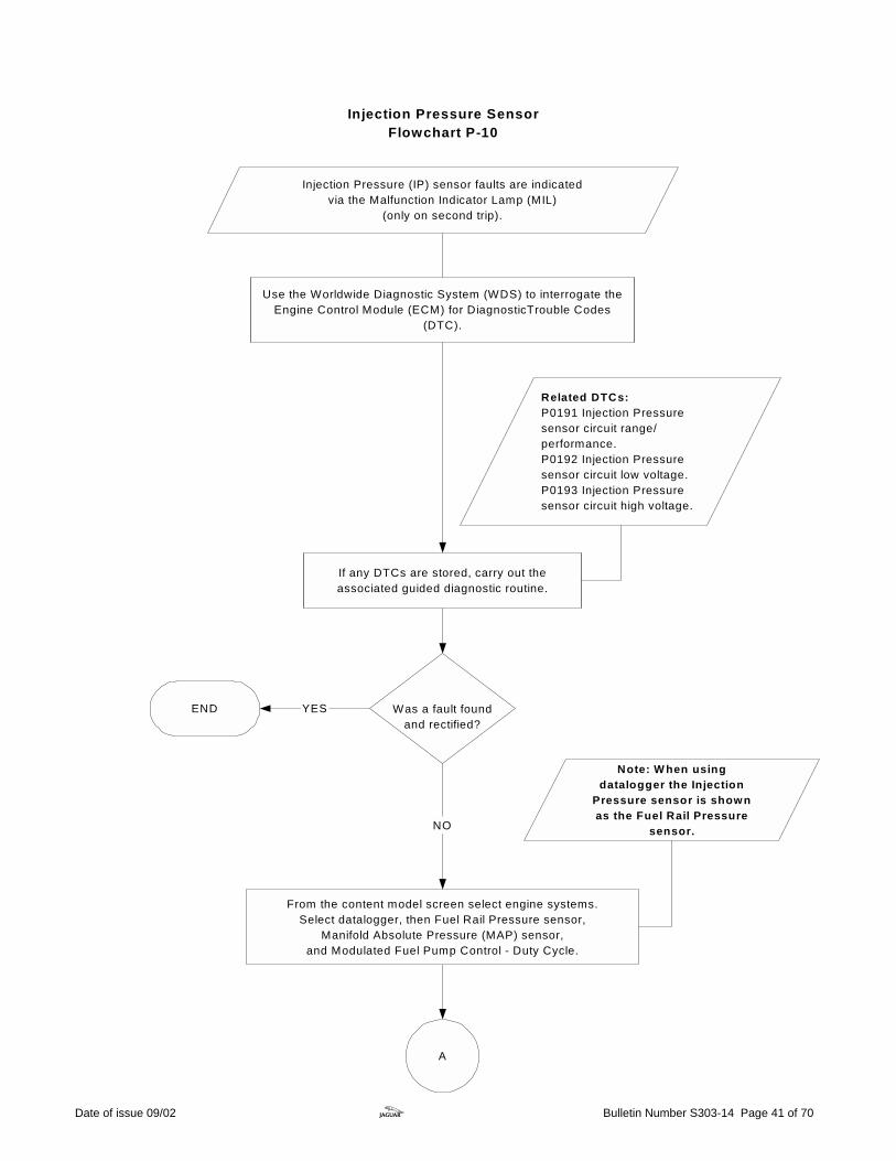
Use the Worldwide Diagnostic System (WDS) to interrogate theEngine Control Module (ECM) for DiagnosticTrouble Codes
(DTC).
Injection Pressure (IP) sensor faults are indicatedvia the Malfunction Indicator Lamp (MIL)
(only on second trip).
If any DTCs are stored, carry out theassociated guided diagnostic routine.
Related DTCs:P0191 Injection Pressuresensor circuit range/performance.P0192 Injection Pressuresensor circuit low voltage.P0193 Injection Pressuresensor circuit high voltage.
Injection Pressure SensorFlowchart P-10
Was a fault foundand rectified?
NO
YESEND
A
From the content model screen select engine systems.Select datalogger, then Fuel Rail Pressure sensor,
Manifold Absolute Pressure (MAP) sensor,and Modulated Fuel Pump Control - Duty Cycle.
Note: W hen usingdatalogger the Injection
Pressure sensor is shownas the Fuel Rail Pressure
sensor.
Date of issue 09/02 z Bulletin Number S303-14 Page 41 of 70
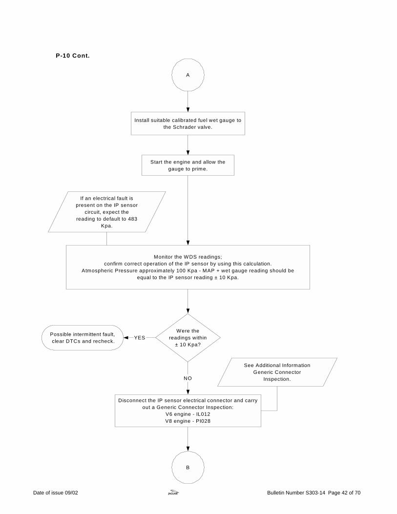
Start the engine and allow thegauge to prime.
A
Monitor the WDS readings;confirm correct operation of the IP sensor by using this calculation.
Atmospheric Pressure approximately 100 Kpa - MAP + wet gauge reading should beequal to the IP sensor reading ± 10 Kpa.
Were thereadings within
± 10 Kpa?YES
NO
Possible intermittent fault, clear DTCs and recheck.
B
See Additional InformationGeneric Connector
Inspection.
If an electrical fault ispresent on the IP sensor
circuit, expect thereading to default to 483
Kpa.
Disconnect the IP sensor electrical connector and carryout a Generic Connector Inspection:
V6 engine - IL012V8 engine - PI028
P-10 Cont.
Install suitable calibrated fuel wet gauge tothe Schrader valve.
Date of issue 09/02 z Bulletin Number S303-14 Page 42 of 70

With the ignition 'ON' and using a DMM,check for 5 volt supply at pin 001 of IP sensor
electrical connector.
Was the reading asexpected?
Carry out Generic Harness Check between the IP sensor electricalconnector and the ECM electrical connector PI001:
V6 - IL012 pin 001 - PI001 pin 012 (Orange and yellow wire)or
V8 - PI028 pin 001 - PI001 pin 012 (Orange and yellow wire)
Ensure the ignition is switched 'OFF' anddisconnect ECM electrical connector PI001.
B
NO
YES
See Additional InformationGeneric Harness Check.
See Additional InformationGeneric Connector
Inspection.
Was a fault foundand rectified?
END YES Contact Technical Hotline for further assistance.NO
C
Carry out a Generic Connector Inspection on ECMelectrical connector PI001.
If the 5 volt supply has beenlost from the ECM, suspect
additional sensor fault codesto be logged.
P-10 Cont.
Date of issue 09/02 z Bulletin Number S303-14 Page 43 of 70

C
Carry out Generic Harness Check between the IP sensor electrical connector andthe ECM electrical connector PI001:
V6 - IL012 pin 003 - PI001 pin 073 (blue wire)IL012 pin 002 - PI001 pin 019 (black and green wire)
orV8 - PI028 pin 003 - PI001 pin 073 (blue wire)
PI028 pin 002 - PI001 pin 019 (black and green wire)
Ensure the ignition is switched 'OFF' anddisconnect ECM electrical connector PI001.
See Additional InformationGeneric Harness Check.
See Additional InformationGeneric Connector
Inspection.
Was a fault foundand rectified?
Replace the IP Sensor.
NO
END YES
Carry out a Generic Connector Inspection on ECMelectrical connector PI001.
P-10 Cont.
Date of issue 09/02 z Bulletin Number S303-14 Page 44 of 70

Knock SensorFlowchart P-11
Use the Worldwide Diagnostic System (WDS) to interrogate theEngine Control Module (ECM) for DiagnosticTrouble Codes
(DTC).
Related DTCs: P0327 Knock sensor bank 1 circuit out of range low voltage. P0328 Knock sensor bank 1 circuit out of range high voltage. P0332 Knock sensor bank 2 circuit out of range low voltage. P0333 Knock sensor bank 2 circuit out of range high voltage. P1648 ECM Knock sensor self test failure.
Knock Sensor (KS) faults are indicated via theMalfunction Indicator Lamp (MIL)
(only on second trip).
A
Note:The vehicle tim ingwill be retarded andthe maxim um enginespeed reduced to3000rpm if a fault lieswith the knocksensor or circuit.
Date of issue 09/02 z Bulletin Number S303-14 Page 45 of 70

A
Disconnect the relevent Knock Sensor electrical connector and carry out a Generic Connector Inspection:
V6 and V8 N/AKS bank 1 - PI020KS bank 2 - PI019
V8 SCKS bank 1 - PI058KS bank 2 - PI019
Using a Digital Multi Meter (DMM) check the resistance across the relevent KS pins 001 and 002
expected reading 120 KOhms - 280 KOhms.Also check to ensure no short circuits are apparent on flylead.
Were the readingsas expected?
NO
Renew the KS.
YESB
See additional informationGeneric connector
inspection.
See Additional InformationGeneric Harness Check.
P-11 Cont.
Date of issue 09/02 z Bulletin Number S303-14 Page 46 of 70

B
See Additional InformationGeneric Connector
Inspection.
Ensure the ignition is switched 'OFF' anddisconnect ECM electrical connector PI001
and carry out a Generic Connector Inspection.
Carry out a Generic Harness Check between the relevent KSelectrical connector and the ECM electrical connector.
Was a fault foundand rectified?
NO
YESEND
See AdditionalInformation
Generic Harness Check.
Where possible check the harness for damagebefore disconnecting the ECM.
If fault persists contact Technical Hotline.
Clear DTCs and road test to the monitoringconditions in the DTC summaries CD.
If fault persists ensure sensor is correctly installedto the cylinder block.
P-11 Cont.
Refer to S-TYPEElectrical Guide.
Date of issue 09/02 z Bulletin Number S303-14 Page 47 of 70
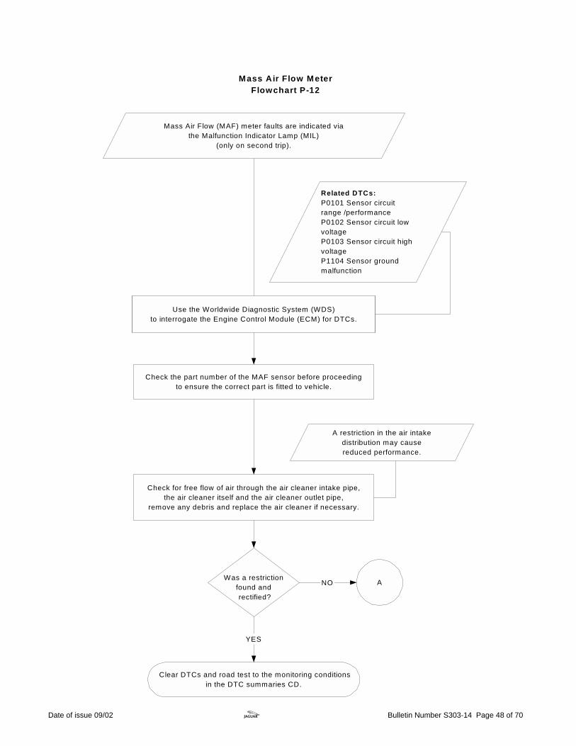
Mass Air Flow MeterFlowchart P-12
Mass Air Flow (MAF) meter faults are indicated viathe Malfunction Indicator Lamp (MIL)
(only on second trip).
Check for free flow of air through the air cleaner intake pipe,the air cleaner itself and the air cleaner outlet pipe,
remove any debris and replace the air cleaner if necessary.
Was a restrictionfound and rectified?
YES
NO
A restriction in the air intakedistribution may causereduced performance.
Clear DTCs and road test to the monitoring conditionsin the DTC summaries CD.
Check the part number of the MAF sensor before proceedingto ensure the correct part is fitted to vehicle.
Related DTCs:P0101 Sensor circuitrange /performanceP0102 Sensor circuit lowvoltageP0103 Sensor circuit highvoltageP1104 Sensor groundmalfunction
A
Use the Worldwide Diagnostic System (WDS)to interrogate the Engine Control Module (ECM) for DTCs.
Date of issue 09/02 z Bulletin Number S303-14 Page 48 of 70

A
Monitor the signal,expected reading at idle
5.0 grams per second - 7.5 grams per second.
Was the reading asexpected?
NO
Note: An increase inengine speed will increase
theMAF reading.
YES
B
Start the engine and run to normal operating temperature,ensure the engine is idling and all engine loads are switched 'OFF'.
Possible intermittent fault. Clear DTCs and road test to the monitoring
conditions in the DTC summaries CD.
P-12 Cont.
Using WDS, select datalogger,engine systems, then select Mass Air Flow Sensor.
Date of issue 09/02 z Bulletin Number S303-14 Page 49 of 70
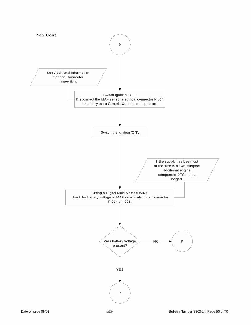
B
Using a Digital Multi Meter (DMM)check for battery voltage at MAF sensor electrical connector
PI014 pin 001.
Switch the ignition 'ON'.
If the supply has been lostor the fuse is blown, suspect
additional enginecomponent DTCs to be
logged.
Was battery voltagepresent?
NO
YES
Switch Ignition 'OFF'.Disconnect the MAF sensor electrical connector PI014
and carry out a Generic Connector Inspection.
D
See Additional InformationGeneric Connector
Inspection.
C
P-12 Cont.
Date of issue 09/02 z Bulletin Number S303-14 Page 50 of 70

Carry out Generic Harness Check between MAFS electricalconnector PI014 and the ECM electrical connector PI001:
PI014 Pin 003 - PI001 pin 044 (Green and white wire)PI014 Pin 002 - PI001 pins 045 (Black and pink wire)PI014 Pin 002 - PI001 pins 046 (Black and pink wire)
C
See Additional InformationGeneric Harness Check.
Was a fault foundand rectified?
END YES
Contact Technical Hotline for further assistance.
NO
See Additional InformationGeneric Connector
Inspection.
When possible check the harness for damagebefore disconnecting the ECM.
Ensure the ignition is switched 'OFF'.Disconnect ECM electrical connector PI001,
and check for any damage.
P-12 Cont.
Date of issue 09/02 z Bulletin Number S303-14 Page 51 of 70
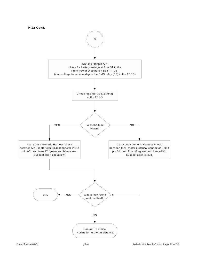
D
Was the fuseblown?
NO
Carry out a Generic Harness checkbetween MAF meter electrical connector PI014
pin 001 and fuse 37 (green and blue wire).Suspect short circuit low.
YES
Was a fault foundand rectified?
YES
Check fuse No. 37 (15 Amp)at the FPDB
Contact Technical Hotline for further assistance.
NO
Carry out a Generic Harness checkbetween MAF meter electrical connector PI014
pin 001 and fuse 37 (green and blue wire).Suspect open circuit.
END
With the ignition 'ON'check for battery voltage at fuse 37 in the
Front Power Distribution Box (FPDB)(if no voltage found investigate the EMS relay (R5) in the FPDB)
P-12 Cont.
Date of issue 09/02 z Bulletin Number S303-14 Page 52 of 70

Throttle MotorFlowchart P-13
Throttle motor faults are indicated via theMalfunction Indicator Lamp (MIL)
(only on second trip).
Use the Worldwide Diagnostic System (WDS) to interrogate theEngine Control Module (ECM) for Diagnostic Trouble Codes
(DTC).
A
Related DTCs: P1229 Throttle motor control circuit malfunction P1224 Throttle control position error P1251Trottle motor relay OFF failure P1658 Relay 'ON' failure P1631 Relay Driver 'OFF' failure P1657 Relay Driver 'ON' failure
END
If any related DTCs are stored, carry out theassociated guided diagnostic routine.
YES Was a fault foundand rectified?
NO
DTC P1582 will belogged if a fault hasoccured with the ThrottlePosition Sensor.This is not a throttle faultcode, but is used forinformation only.
Date of issue 09/02 z Bulletin Number S303-14 Page 53 of 70

A periodic clicking noise willbe heard from the throttlemotor when the ignition isswitched 'ON' and 'OFF.'
A
Was the motoroperating?
NO
YES
Switch the ignition 'ON'.Operate the throttle pedal to see the throttle plate
open and close.
Check that the throttle valve returns to itsoriginal position but does not completely close
and that the plate is moving smoothly.
Was a fault found?YESReplace throttle body.
NO
DTC P1250 or P1254 maybe logged if a fault has
occurred with the operationof the throttle return spring.
B
Ensure that throttle plateis clear of debris and
excessive blackdeposits are removed.
Remove the air cleaner outlet pipe from the throttlebody to see the throttle plate operate.
Clear DTCs and road test to themonitoring conditions in the DTC
summaries CD.
The throttle motor maybe inhibited if a throttle
DTC is logged.
P-13 Cont.
Date of issue 09/02 z Bulletin Number S303-14 Page 54 of 70
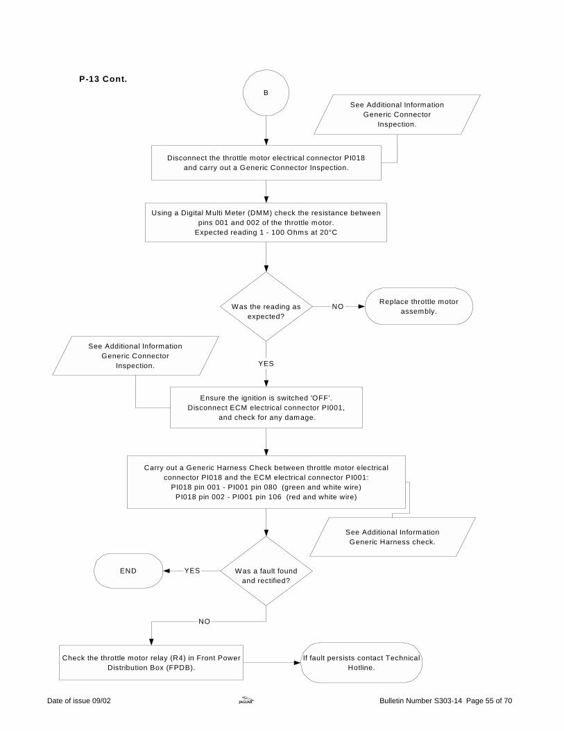
B
Carry out a Generic Harness Check between throttle motor electricalconnector PI018 and the ECM electrical connector PI001:
PI018 pin 001 - PI001 pin 080 (green and white wire)PI018 pin 002 - PI001 pin 106 (red and white wire)
Was a fault foundand rectified?
YES
NO
END
See Additional InformationGeneric Connector
Inspection.
If fault persists contact TechnicalHotline.
Ensure the ignition is switched 'OFF'.Disconnect ECM electrical connector PI001,
and check for any damage.
YES
Disconnect the throttle motor electrical connector PI018and carry out a Generic Connector Inspection.
Using a Digital Multi Meter (DMM) check the resistance betweenpins 001 and 002 of the throttle motor.
Expected reading 1 - 100 Ohms at 20°C
Was the reading asexpected?
NO Replace throttle motorassembly.
See Additional InformationGeneric Connector
Inspection.
P-13 Cont.
Check the throttle motor relay (R4) in Front PowerDistribution Box (FPDB).
See Additional InformationGeneric Harness check.
Date of issue 09/02 z Bulletin Number S303-14 Page 55 of 70

V6/V8 N/A Variable Valve TimingFlowchart P-14
Related DTCs:P0010 VVT side 1 circuitmalfunctionP1384 VVT side 1malfunctionP0020 VVT side 2 circuitmalfunctionP1396 VVT side 2malfunction
Use the Worldwide Diagnostic System (WDS) tointerrogate the Engine Control Module (ECM) for
DiagnosticTrouble Codes (DTC).
Monitor the signals.
Note: Fluctuating the engine speed and loadwill cause a change in the duty cycle applied
to the VVT (0-100% ), monitor both signalsand compare the readings. If the VVT in
question has no duty applied (0%) there isan electrical fault on the circuit from theECM and either P0010 or P0020 will be
logged.
A
Variable Valve Timing (VVT) solenoid faults are indicatedvia the Malfunction Indicator Lamp (MIL)
(only on the second trip).
Using WDS, select datalogger, engine systems thenselect Variable Camshaft Timing duty cycle for both
VVT solenoids.
Note: W hen usingdatalogger the VVT
is shown asVariable Camshaft
Tim ing.
Date of issue 09/02 z Bulletin Number S303-14 Page 56 of 70
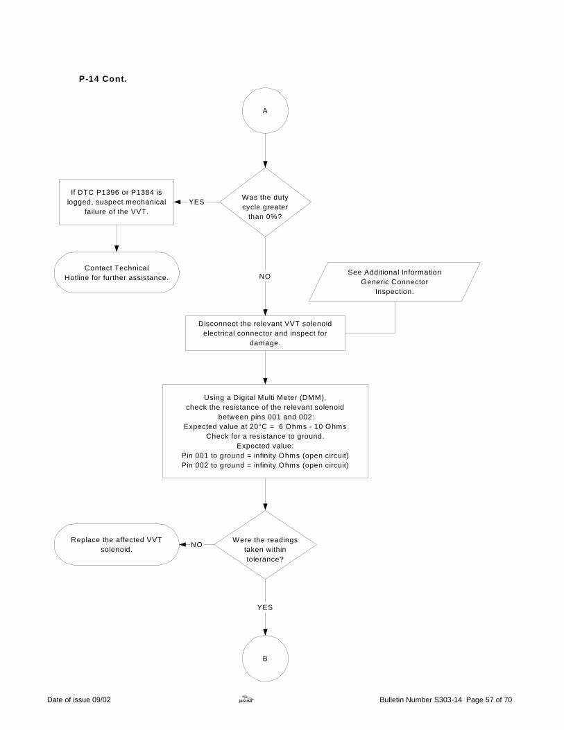
Disconnect the relevant VVT solenoidelectrical connector and inspect for
damage.
See Additional InformationGeneric Connector
Inspection.
Using a Digital Multi Meter (DMM),check the resistance of the relevant solenoid
between pins 001 and 002:Expected value at 20°C = 6 Ohms - 10 Ohms
Check for a resistance to ground.Expected value:
Pin 001 to ground = infinity Ohms (open circuit)Pin 002 to ground = infinity Ohms (open circuit)
Were the readingstaken withintolerance?
NO
YES
B
Was the dutycycle greater
than 0%?
A
NO
YESIf DTC P1396 or P1384 is
logged, suspect mechanicalfailure of the VVT.
Contact TechnicalHotline for further assistance.
Replace the affected VVTsolenoid.
P-14 Cont.
Date of issue 09/02 z Bulletin Number S303-14 Page 57 of 70

Carry out Generic Harness Check between the relevant VVT solenoidengine harness electrical connector and the ECM electrical connector
VVT solenoid bank 1:PI016 pin 001 - PI001 pin 109 (Yellow wire)
PI016 pin 002 - ground eyelet PI040AR (Black wire)VVT solenoid bank 2
PI017 pin 001 - PI001 pin 110 (Yellow and blue wire)PI017 pin 002 - ground eyelet PI040AR (Black wire)
Was a fault foundand rectified?
END YES
B
See Additional InformationGeneric Harness Check.
Contact TechnicalHotline for further assistance.
NO
Refer to S-TYPEElectrical Guide.
Ensure the ignition is switched 'OFF'.Disconnect ECM electrical connector PI001,
and check for any damage.
See Additional InformationGeneric Connector
Inspection.
When possible check the harness fordamage before disconnecting the ECM.
P-14 Cont.
Date of issue 09/02 z Bulletin Number S303-14 Page 58 of 70
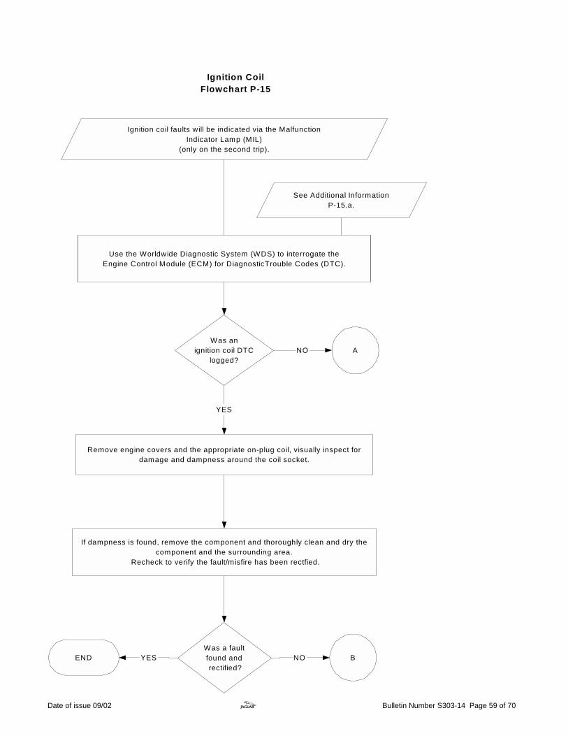
Ignition CoilFlowchart P-15
Use the Worldwide Diagnostic System (WDS) to interrogate theEngine Control Module (ECM) for DiagnosticTrouble Codes (DTC).
Ignition coil faults will be indicated via the MalfunctionIndicator Lamp (MIL)
(only on the second trip).
Was anignition coil DTC
logged?NO
YES
Remove engine covers and the appropriate on-plug coil, visually inspect fordamage and dampness around the coil socket.
A
B
If dampness is found, remove the component and thoroughly clean and dry thecomponent and the surrounding area.
Recheck to verify the fault/misfire has been rectfied.
Was a faultfound and rectified?
NOYESEND
See Additional InformationP-15.a.
Date of issue 09/02 z Bulletin Number S303-14 Page 59 of 70

Was a suspect cylinder
identified?
NO
With the engine running, disconnect each ignition coil electrical connector in turn.Listen to the engine tone, the misfire will deteriorate and the engine speed will drop, if the cylinder is 'GOOD'.
Reconnect the connector and move to the next cylinder.When the cylinder with the misfire is disconnected no change will be apparentW ARNING: USE GREAT CARE W HILE THE ENGINE IS RUNNING!
YES
A
Possible intermittent fault or otherreason for failure.
Investigate any other DTCs logged.
B
Remove engine covers, visually inspect for damage and dampnessaround the on-plug coil areas.
If dampness is found remove the component and thoroughly clean and drythe component and the surrounding area.
Recheck to verify the fault/misfire has been rectified.
NO
YESEND
Remove any necessary parts to safely allow access to the ignitioncoils on both banks while the engine is running.
W ARNING: USE GREAT CARE WHILE THE ENGINE IS RUNNING!
Was a faultfound and rectified?
P-15 Cont.
Date of issue 09/02 z Bulletin Number S303-14 Page 60 of 70

Using the WDSclear all DTCs logged while carrying
out the ignition coil tests.
Remove the Ignition coil.Substitue with known good ignition coil and retry.
B
Has the fault been rectified?
Replace ignition coil and spark plug. YES NO
C
From the DTC logged or the suspect cylinder disconnect the relevant ignition coil
electrical connector and carry out GenericConnector Inspection.
See Additional InformationAppendix P-15.a.
See additional informationGeneric Connector
Inspection.
Has the fault been rectified?
Replace the spark plugand retry.
NO
YES
P-15 Cont.
Date of issue 09/02 z Bulletin Number S303-14 Page 61 of 70
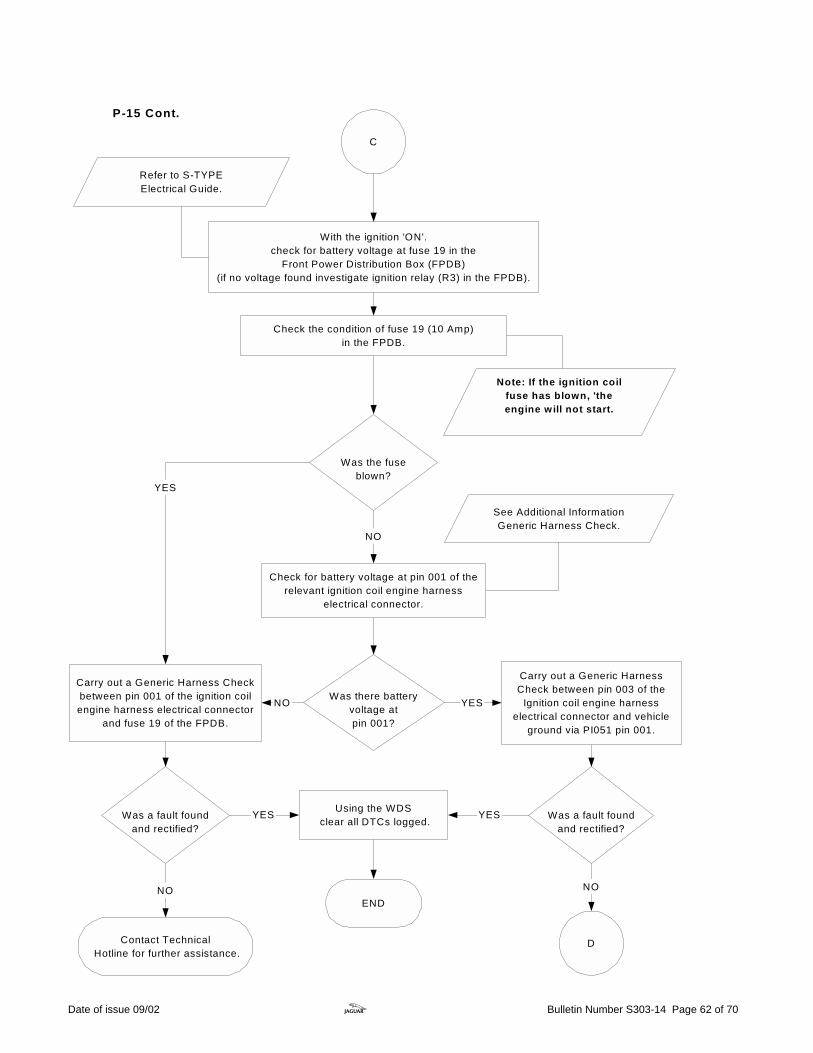
Check for battery voltage at pin 001 of therelevant ignition coil engine harness
electrical connector.
NO
Was a fault foundand rectified?
NO
See Additional InformationGeneric Harness Check.
YES
NO
D
C
With the ignition 'ON'.check for battery voltage at fuse 19 in the
Front Power Distribution Box (FPDB)(if no voltage found investigate ignition relay (R3) in the FPDB).
Was the fuseblown?
Was there batteryvoltage atpin 001?
Carry out a Generic Harness Checkbetween pin 001 of the ignition coilengine harness electrical connector
and fuse 19 of the FPDB.
NO
Was a fault foundand rectified?
END
YES
Carry out a Generic HarnessCheck between pin 003 of the
Ignition coil engine harnesselectrical connector and vehicle
ground via PI051 pin 001.
YES
YES
Contact Technical Hotline for further assistance.
Check the condition of fuse 19 (10 Amp)in the FPDB.
Note: If the ignition coilfuse has blown, 'theengine will not start.
Using the WDS clear all DTCs logged.
Refer to S-TYPEElectrical Guide.
P-15 Cont.
Date of issue 09/02 z Bulletin Number S303-14 Page 62 of 70

D
Ensure the ignition is switched 'OFF'.
Disconnect ECM electrical connector PI001and carry out Connector Inspection.
Carry out a Generic Harness Check between pins 002 and 004of the relevant ignition coil engine harness electrical
connector and the relevant ECM electrical connector pins.
See AdditionalInformation
Generic Harness Check.
Was a fault foundand rectified?
END YES
Contact Technical Hotline if fault persists.
See Additional InformationGeneric Connector
Inspection.
Refer to the S-TYPEElectrical Guide on
JTIS.
NO
Where possible check the harness for damagebefore disconnecting the ECM.
P-15 Cont.
Date of issue 09/02 z Bulletin Number S303-14 Page 63 of 70
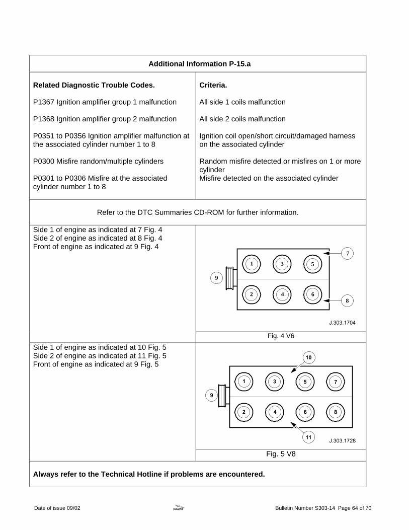
Additional Information P-15.a Related Diagnostic Trouble Codes. P1367 Ignition amplifier group 1 malfunction P1368 Ignition amplifier group 2 malfunction P0351 to P0356 Ignition amplifier malfunction at the associated cylinder number 1 to 8 P0300 Misfire random/multiple cylinders P0301 to P0306 Misfire at the associated cylinder number 1 to 8
Criteria. All side 1 coils malfunction All side 2 coils malfunction Ignition coil open/short circuit/damaged harness on the associated cylinder Random misfire detected or misfires on 1 or more cylinder Misfire detected on the associated cylinder
Refer to the DTC Summaries CD-ROM for further information.
1 3
2 4
5
6
9
7
8
Side 1 of engine as indicated at 7 Fig. 4 Side 2 of engine as indicated at 8 Fig. 4 Front of engine as indicated at 9 Fig. 4
Fig. 4 V6
Side 1 of engine as indicated at 10 Fig. 5 Side 2 of engine as indicated at 11 Fig. 5 Front of engine as indicated at 9 Fig. 5
Fig. 5 V8 Always refer to the Technical Hotline if problems are encountered.
Date of issue 09/02 z Bulletin Number S303-14 Page 64 of 70

Throttle Position SensorFlowchart P-16
Use the Worldwide Diagnostic System (WDS) to interrogate the Engine ControlModule (ECM) for Diagnostic Trouble Codes (DTC).
Throttle Position SensorRelated DTCs:P0121 TP sensor circuit 1and 2 range/performanceP0122 TP sensor circuit 1low inputP0123 TP sensor circuit 1high inputP0222 TP sensor circuit 2low inputP0223 TP sensor circuit 2high input
Throttle Position (TP) sensor faults are indicatedvia the Malfunction Indicator Lamp (MIL)
(only on second trip).
A
DTC P1582 will belogged if a fault hasoccured with the ThrottlePosition Sensor.This is not a throttle faultcode, but is used forinformation only.
Using WDS, select datalogger, fuel system and then select,Throttle Position sensor, track 1 (central processor unit 1)Throttle Position sensor, track 2 (central pocessor unit 1)
Date of issue 09/02 z Bulletin Number S303-14 Page 65 of 70
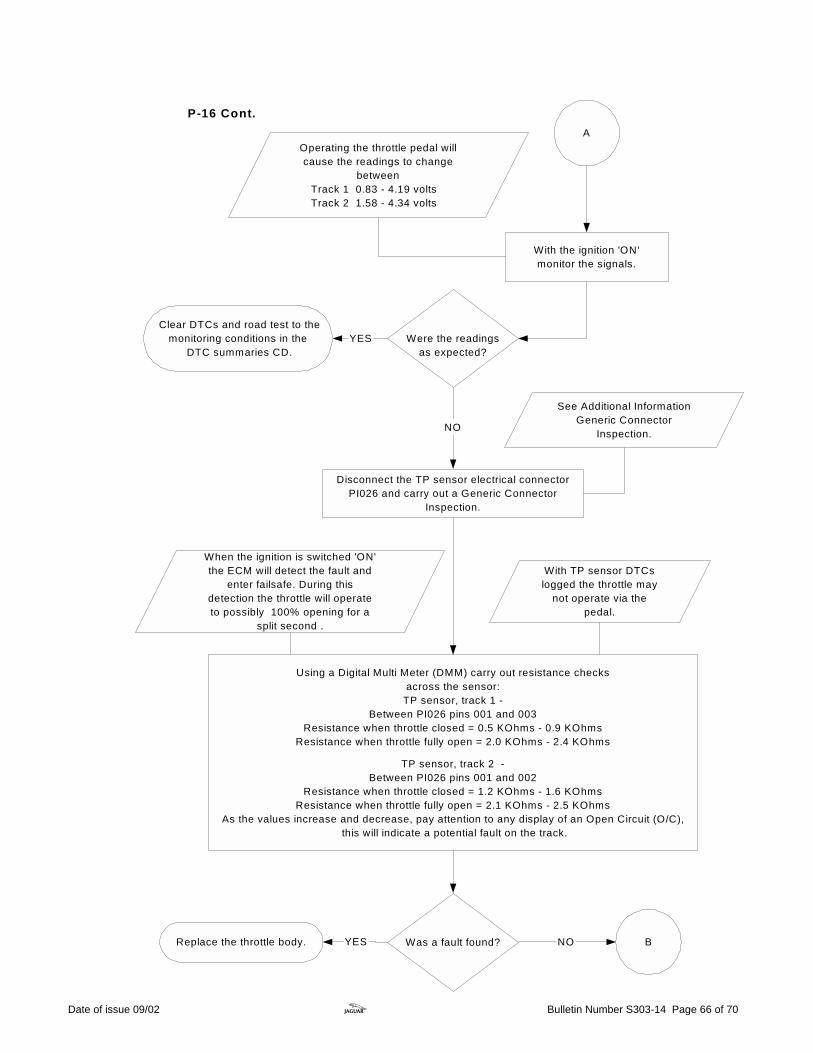
A
Were the readingsas expected?
YES
NO
With the ignition 'ON'monitor the signals.
Operating the throttle pedal willcause the readings to change
betweenTrack 1 0.83 - 4.19 voltsTrack 2 1.58 - 4.34 volts
Disconnect the TP sensor electrical connectorPI026 and carry out a Generic Connector
Inspection.
See Additional InformationGeneric Connector
Inspection.
Using a Digital Multi Meter (DMM) carry out resistance checksacross the sensor:
TP sensor, track 1 -Between PI026 pins 001 and 003
Resistance when throttle closed = 0.5 KOhms - 0.9 KOhmsResistance when throttle fully open = 2.0 KOhms - 2.4 KOhms
TP sensor, track 2 -Between PI026 pins 001 and 002
Resistance when throttle closed = 1.2 KOhms - 1.6 KOhmsResistance when throttle fully open = 2.1 KOhms - 2.5 KOhms
As the values increase and decrease, pay attention to any display of an Open Circuit (O/C), this will indicate a potential fault on the track.
Was a fault found?YESReplace the throttle body. BNO
Clear DTCs and road test to themonitoring conditions in the
DTC summaries CD.
With TP sensor DTCslogged the throttle may
not operate via thepedal.
When the ignition is switched 'ON'the ECM will detect the fault and
enter failsafe. During thisdetection the throttle will operateto possibly 100% opening for a
split second .
P-16 Cont.
Date of issue 09/02 z Bulletin Number S303-14 Page 66 of 70

With the ignition 'ON' and using a DMM,check for 5 volt supply at TP sensor electrical
connector PI026 pin 004.
Was the reading asexpected?
Carry out Generic Harness Check between TP sensor electricalconnector PI026 and the ECM electrical connector PI001PI026 pin 004 - PI001 pin 012 (orange and yellow wire).
Ensure the ignition is switched 'OFF'.Disconnect ECM electrical connector PI001,
and check for any damage.
B
NO
YES
See Additional InformationGeneric Harness Check.
See Additional InformationGeneric Connector
Inspection.
Was a fault foundand rectified?
END YES Contact Technical Hotline for further assistance.NO
C
If the 5 volt supply has beenlost from the ECM, suspect
additional ECM sensorDTCs to be logged.
Refer to the S-TYPEElectrical Guide.
Datalogger on WDScan be used to monitor
the 5 volt supply, byselecting Sensor
Power Supply Monitorwithin Engine systems.
Where possible check the harness fordamage before disconnecting the ECM.
P-16 Cont.
Date of issue 09/02 z Bulletin Number S303-14 Page 67 of 70
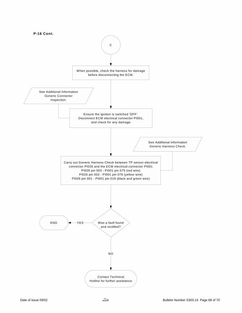
C
Carry out Generic Harness Check between TP sensor electricalconnector PI026 and the ECM electrical connector PI001
PI026 pin 003 - PI001 pin 075 (red wire)PI026 pin 002 - PI001 pin 076 (yellow wire)
PI026 pin 001 - PI001 pin 019 (black and green wire)
See Additional InformationGeneric Harness Check.
See Additional InformationGeneric Connector
Inspection.
Was a fault foundand rectified?
Contact Technical Hotline for further assistance.
NO
END YES
Ensure the ignition is switched 'OFF'.Disconnect ECM electrical connector PI001,
and check for any damage.
When possible, check the harness for damagebefore disconnecting the ECM.
P-16 Cont.
Date of issue 09/02 z Bulletin Number S303-14 Page 68 of 70
Generic Connector Inspection Electrical failures can be caused by problems with the connectors and their pins. Below are a number of points that may aid in investigation.
Backed-out Pins Inspection of the connector; look for signs that the pin has backed-out. If a seal is fitted to the pin it may be protruding further out the back of the connector. If a pin has backed-out of the cavity in the connector, there is a possibility that it has been forced out when the connector was mated. Make sure that the pins are in line when the two halves of the connector are mated.
Bent Pins Disconnect the two halves of the connector and visually inspect the pins. If a pin is bent over there is a possibility of a short from pin to pin. Pins can easily be bent over when the connector is mated. Check to ensure the pins within the connector are not out of alignment before the two halves of the connector are mated.
Water ingress/fluid ingress Disconnect the connector and inspect for signs of water ingress. Corrosion may have occurred. If water or any other fluid is visible this may cause a bad connection or even short circuit to the other pins within the connector. Examine the connector seals for any damage and to ensure that the seals are fitted correctly. Ensure that the two halves of the connector latch together securely.
Probing Ensure when probing a pin that the correct probe is used and excessive force is not used as this may weaken the locating clip and allow the pin to work loose. Care must be taken when probing female pins as the pin can easily be splayed if probed with the incorrect adaptor or the wrong tool. This would then have the potential to cause a bad connection between the two mating halves. Always use the Worldwide Diagnostic System probe kit when probing pins within a connector. (Jaguar probe adaptor kit part number. 3548-1358-00.)
Insertion force Insertion force is imperative to ensure a good connection is made between the two mating pins. If the female pin is splayed, the connection will be poor. To check the insertion force of the female connector, identify the correct male pin within WDS probe adaptor kit. Gently insert the adaptor into the female pin and then repeat with the other pins within the connector. If the pin in question feels loose in comparison replace both male and female pins.
Chafing Inspect the harness when in close contact to other objects (i.e. sharp steel brackets). Engine vibration will cause the outer protection to quickly chafe through if the harness is not routed correctly. When performing a repair, ensure that heat resistant tape is used where relevant. Before repairing or renewing any harness, always refer to the Electrical Wiring Harness Repair Guide, reference publication number JTP 586. When repairing a harness ensure the Jaguar harness repair kit is used. (Part number. 418-S065 and 418-S411.) Always refer to the Technical Hotline if problems are encountered.
Date of issue 09/02 z Bulletin Number S303-14 Page 69 of 70

Date of issue 09/02 z Bulletin Number S303-14 Page 70 of 70
Generic Harness Check • When carrying out any of the tests in the generic harness check, it is imperative that any other
sources that share the harness are taken into consideration when a measurement is taken. • The S-TYPE Electrical Guide will show all other sources sharing that harness i.e. splices and
sensors. • Always ensure the digital voltmeter is operating correctly before proceeding. • Always use the WDS probe kit when probing pins within a connector.
Note: Do not insert the Digital Multi Meter (DMM) leads into the connector pins. (Probe adaptor kit part number: 3548-1358-00.)
Continuity test Using a DMM, connect the DMM to the pins at both ends of the circuit that you are testing. Ensure you connect to the correct pin when a large number of pins are used in a connector. (Use WDS Probe adapter kit). Set the DMM to the resistance test or the continuity beeper. The resistance should be between 0 and 10 ohms. If a high resistance or open circuit is found investigate harness for damage.
Short circuit high fault The DMM can be connected to any ground source on the vehicle, but it is preferable to use the battery negative pole. Set the DMM to Volts DC; connect the DMM red probe to the suspect pin of the circuit and the DMM black probe to the battery negative pole. No voltage should be seen. If 4 – 13 volts is seen, suspect short circuit high and investigate harness for damage. Always test the circuit with the ignition 'ON' and 'OFF' when trying to identify this fault condition.
Short circuit low fault (to ground) The DMM can be connected to any ground source on the vehicle, but it is preferable to use the battery negative pole. Set the DMM to the resistance test; connect the DMM to the suspect pin of the circuit and the battery negative pole. An infinity reading/open circuit (O/C) should be seen. If a resistance is seen, suspect short circuit low and investigate harness for damage.
Always refer to the Technical Hotline if problems are encountered.