service manual trucks - heavy · service manual trucks group 38 instrumentation – 1996b ......
TRANSCRIPT

Service ManualTrucks
Group 38
Instrumentation – 1996BVNL, VNM — from 1/98
PV776-TSP106805/1
Foreword
The descriptions and service procedures contained in this manual are based on de-signs and methods studies carried out up to February 1998.
The products are under continuous development. Vehicles and components producedafter the above date may therefore have different specifications and repair methods.When this is believed to have a significant bearing on this manual, supplementary ser-vice bulletins will be issued to cover the changes.
The new edition of this manual will update the changes.
In service procedures where the title incorporates an operation number, this is a refer-ence to an V.S.T. (Volvo Standard Times).
Service procedures which do not include an operation number in the title are for gen-eral information and no reference is made to an V.S.T.
The following levels of observations, cautions and warnings are used in this ServiceDocumentation:
Note: Indicates a procedure, practice, or condition that must be followed in order tohave the vehicle or component function in the manner intended.
Caution: Indicates an unsafe practice where damage to the product could occur.
Warning: Indicates an unsafe practice where personal injury or severe damage to theproduct could occur.
Danger: Indicates an unsafe practice where serious personal injury or death could oc-cur.
Volvo Trucks North America, Inc.Greensboro, NC USA
Order number: PV776-TSP106805/1
© 1998 Volvo Trucks North America, Inc., Greensboro, NC USA
All rights reserved. No part of this publication may be reproduced, stored inretrieval system, or transmitted in any forms by any means, electronic, me-chanical, photocopying, recording or otherwise, without the prior writtenpermission of Volvo Trucks North America, Inc..
USA06444
ContentsGeneral .................................................................................................... 3
General Work Practices ........................................................................ 3Basic Description ................................................................................... 4
Tools ........................................................................................................ 9Special Tools ......................................................................................... 9Special Equipment ............................................................................... 10
Design and Function ........................................................................... 11Instrument Cluster ................................................................................. 11
Instrument Cluster Functional Diagram ............................................... 11Gauges and Indicators ........................................................................ 13Connector Pinouts ............................................................................... 33
Troubleshooting ................................................................................... 37Instrumentation Troubleshooting ............................................................ 37
General Service Information ................................................................ 37Troubleshooting Notes ......................................................................... 38Gauges, Troubleshooting ..................................................................... 39Gauges, Troubleshooting (with Pro-Link) ............................................ 57
Service Procedures ............................................................................. 59Warranty Notice ................................................................................... 60Odometer, Programming ..................................................................... 60Housing and Front Panel Glass, Cleaning .......................................... 60Bulb, Replacement .............................................................................. 61Instrument Cluster, Replacement ........................................................ 62Right Module, Replacement ................................................................ 63Center Module, Replacement .............................................................. 66Tachometer, Speedometer and Odometer, Replacement ................... 71Left Gauge Module, Replacement ...................................................... 73
Feedback
Operation Numbers
1

2

Group 38 Instrumentation, VNL, VNM General
GeneralGeneral Work Practices
CAUTION
When servicing or troubleshooting, do not leave thecluster face-down for more than 15 minutes, ordamage to the gauges may occur. Gauge oil may runout of the front of the gauge faces and make thegauges inaccurate.
CAUTION
Welding on trucks can damage the vehicle electricalsystem/components from the voltage and currentspikes that normally occur when welding. It is prefer-able to avoid welding on an assembled truck, but ifwelding must be done on any structure on or incontact with the vehicle, disconnect the electrical con-nectors at the rear of the instrument cluster, all ECU’sand the battery cables. When disconnecting the bat-tery cables, disconnect any other ground cablesconnected to the battery first, then the main batteryground. Attach the welder ground cable as close tothe weld as possible.
Preventing electrostatic discharge(ESD)
CAUTION
To prevent electrostatic discharge (ESD), which maydamage the sensitive electronic components in the in-strument cluster, a wrist grounding strap must beused when working on electronic equipment such asthe instrument cluster. Failure to use a wrist strap mayresult in permanent damage to the printed circuitboards in the instrument cluster. To use the wrist strapin a vehicle, attach the alligator clip to the nearestelectrical ground such as a metal mounting screw, aground terminal or preferably a ground stud.
CAUTION
To prevent electrostatic discharge (ESD), which maydamage the sensitive electronic components in the in-strument cluster, make sure the workbench has ananti-static mat which is grounded to the nearest elec-trical outlet when working on the instrument cluster.Failure to use an anti-static mat may result in perma-nent damage to the printed circuit boards in theinstrument cluster. When working at the anti-staticworkbench, always keep a wrist strap connected tothe anti-static mat.
When dealing with circuits designed to sense differencessmaller than 1 volt, electrostatic discharge can be a sub-tle but destructive problem. Circuit boards mounted inthe instrument cluster or in modules mounted elsewheremay not fail immediately after being hit with a static dis-charge. Rather they may work for a while, then fail for noapparent reason. The culprit then is often the normalwarming up and cooling down process of the module,engine or cab interior.
Grounding straps and anti-static mats are available forminimal cost from electronic supply stores. Groundingstraps consist of a wrist strap, a coiled extension wireand an alligator clip. Be sure to purchase one with a longenough extension wire to allow freedom of movement.
Anti-static wrist straps and mats are available fromKent-Moore (see). Call 1-800-328-6657.
3

Group 38 Instrumentation, VNL, VNM General
Basic Description
T3009000
Fig. 1:
This information describes the 1996B AMETEK/Dixson Instrument Cluster for VN Se-ries vehicles and how to service it. This instrument cluster went into production inJanuary 1998. It is distinguished from the earlier VN instrument cluster by the locationof the Mode/Set and Up/Down buttons on the stalk arm. The earlier model had thesebuttons on the face of the cluster. For information about the vehicle’s Electronic ControlUnits, wiring diagrams, sensors and other components, please refer to the service in-formation or electrical schematic for that component.
The cluster is available in 7 configurations, with either an mph or km/h speedometer.
The instrument cluster is divided into the following sections:
• Left Section - Contains a Coolant Temperature and an Oil Pressure gauge, andoptionally, a Pyrometer and a Turbo Boost gauge. A Graphic Display module at thebottom provides additional information about the vehicle. Also contains four telltaleindicators: Engine Fluids, Caution, Stop and No Charge.
• Center Section - Contains a tachometer, speedometer and odometer. Also con-tains a buzzer, fourteen telltale indicators and a Master Warning indicator. Telltalesin this section are: Left and Right Turn Indicators, Fifth Wheel Lock, Wheel Differ-ential Lock, Interaxle Differential Lock, High Beam Indicator, SRS (Air Bag),Parking Brake, Anti-Lock Brake System (ABS) for Tractor (and ABS for Trailer —for future use), Air Suspension, Bogie and Mirror Defroster.
• Right Section - Contains a Fuel Level gauge, a Front Brake Air Pressure gauge,and a Rear Brake Air Pressure gauge. It may also contain an optional ApplicationAir Pressure gauge, an optional Air Suspension gauge and a Forward Axle and aRear Axle Temperature gauge. It can also contain up to six telltale indicators.Standard telltales are Traction Control System and A/C Diagnostic System (for fu-ture use).
Note that all gauges and telltales may not be used in all vehicles.
Four push-buttons on the wiper/washer stalk allow the driver to access and display in-formation in the Graphic Display.
SpecificationsThis instrument cluster is designed to operate with an input voltage of between +10and +18 volts.
4

Group 38 Instrumentation, VNL, VNM General
Available Configurations
T3009001
Fig. 2:
5

Group 38 Instrumentation, VNL, VNM General
Available Configurations (contd.)
T3009002
Fig. 3:
6

Group 38 Instrumentation, VNL, VNM General
Available Configurations (contd.)
T3009303
Fig. 4:
7

8

Group 38 Instrumentation, VNL, VNM Tools
ToolsSpecial Tools
The following special tools are required for work on the instrument cluster. The toolscan be ordered as listed below.
W0001517
Fig. 5:
104004 Pro-link 9000(available from MPSI at 1-800-639-6774)
1089953 Bulb Removal Tool(available from Volvo)
206040 Pro-Link Adapter(available from MPSI)
404024 Diagnostic Cable(available from MPSI)
807012 Volvo Application Card(available from MPSI)
501002 Power/Data Cable(available from MPSI)
9
Group 38 Instrumentation, VNL, VNM Tools
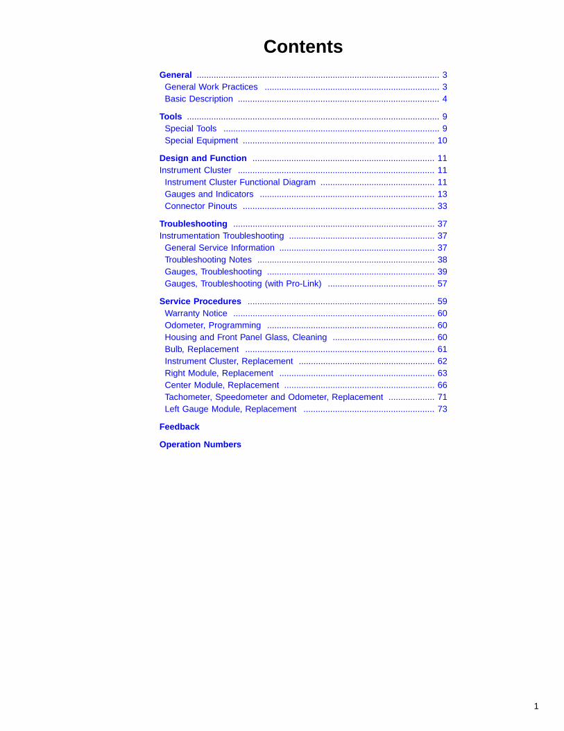
Special EquipmentThe following items are required for work on the instrument cluster. They can be or-dered as shown below.
W0001518
Fig. 6:
J-42444 Type 8501 Static Dissipative Grounding Kit, available fromKent-Moore (1-800-328-6657).The kit shown includes both a wrist strap and anti-static mat.Use both when working on the instrument cluster at a work-bench.
BT-8639-B ESD Wrist Strap, available from Kent-Moore.Use a wrist strap when servicing the instrument cluster in-side the vehicle. Use a wrist strap and anti-static mat whenworking on the instrument cluster at a workbench.
J-39200 Fluke 87 Digital Multi-meter (DMM), available from Kent-Moore.
10

Group 38 Instrumentation, VNL, VNM Design and Function
Design and Function
Instrument ClusterInstrument Cluster Functional Diagram
Volvo Engines
W3002521
Fig. 7:
11

Group 38 Instrumentation, VNL, VNM Design and Function
Caterpillar, Cummins, Detroit Diesel Engines
W3002520
Fig. 8:
12

Group 38 Instrumentation, VNL, VNM Design and Function
Gauges and Indicators
Left Section
Pyrometer (optional)The pyrometer indicates exhaust temperature from asensor in the exhaust system.
The pyrometer gauge is an electrical aircore metermovement driven by a small electric current from a high-temperature thermocouple.
If the pyrometer thermocouple fails, the pointer will moveto one end of the dial or the other. A reading of 149�C(300�F) or less indicates an open in the truck’s wiring orthermocouple, and a reading of 815�C (1500�F) or moreindicates a short.
T3009003
Fig. 9:
Engine Coolant TemperatureThe coolant temperature gauge is an electrical aircoremeter movement which receives its signal from the en-gine via the SAE J1587 data bus. In the absence of adata signal, the gauge pointer will move to its minimumreading after a 3–5 second delay.
Red Warning LED illuminates when coolant temperatureis too high for safe operation. The temperature which ac-tivates this LED is engine-dependent.
W3001304
Fig. 10:
Turbo Boost Pressure (optional)The turbo boost pressure gauge is an electrical aircoremeter movement driven by a signal from the J1587 datalink. In the absence of a data signal, the gauge pointerwill move to its minimum reading after a 3–5 second de-lay.
T3009294
Fig. 11:
13
Group 38 Instrumentation, VNL, VNM Design and Function
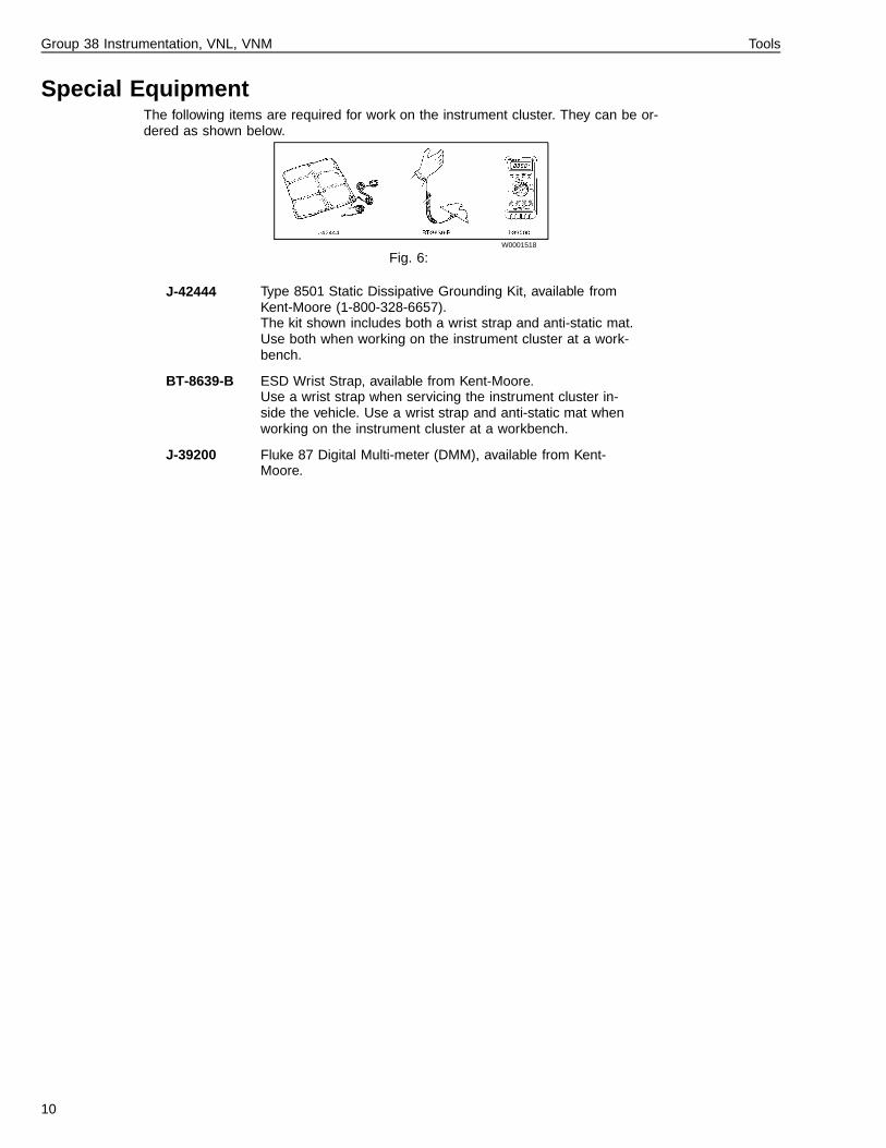
Engine Oil PressureThe engine oil pressure gauge is an electrical aircoremeter movement that receives its signal from a senderunit mounted on the engine. The sender unit suppliesdata to the Engine ECU which sends engine oil pressureinformation to the instrument cluster via the J1587 datalink.
In the absence of a data signal, the gauge pointer willmove to its minimum reading after a 3–5 second delay.
Note: Engine oil operating pressure is engine dependent.
A Red Warning LED illuminates when engine oil pres-sure is too low for safe operation. The pressure whichactivates this LED is engine-dependent. W3000603
Fig. 12:
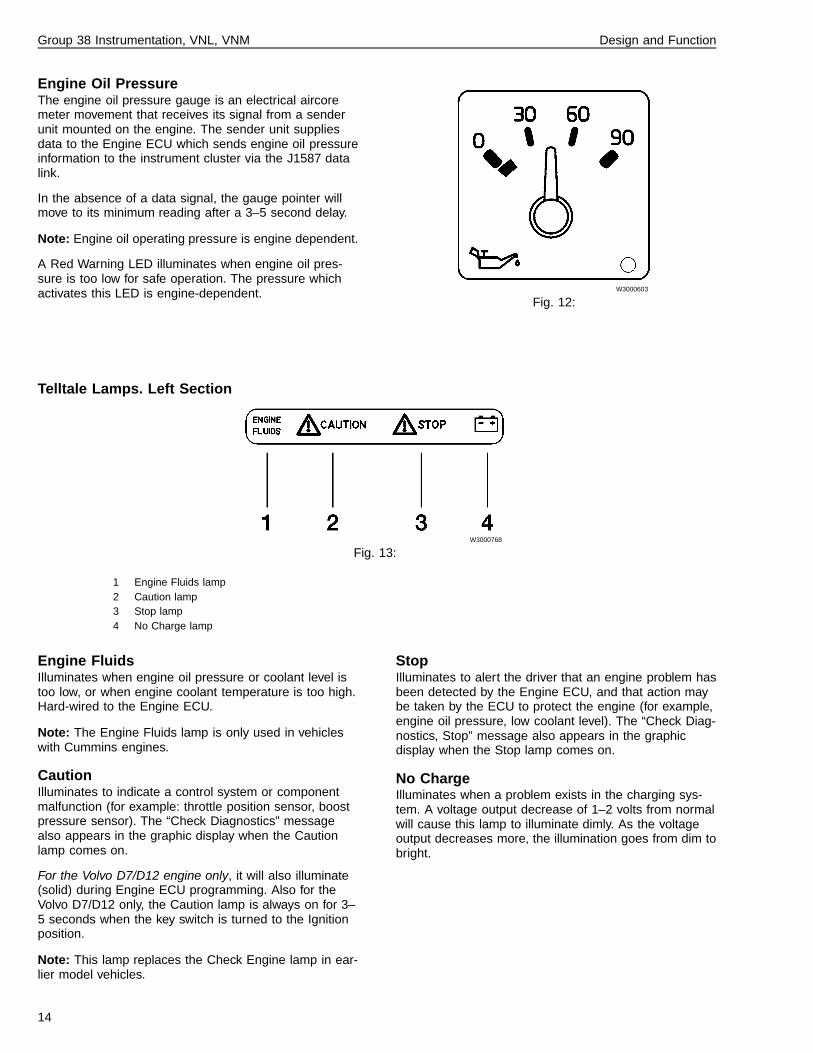
Telltale Lamps. Left Section
W3000768
Fig. 13:
1 Engine Fluids lamp2 Caution lamp3 Stop lamp4 No Charge lamp
Engine FluidsIlluminates when engine oil pressure or coolant level istoo low, or when engine coolant temperature is too high.Hard-wired to the Engine ECU.
Note: The Engine Fluids lamp is only used in vehicleswith Cummins engines.
CautionIlluminates to indicate a control system or componentmalfunction (for example: throttle position sensor, boostpressure sensor). The “Check Diagnostics” messagealso appears in the graphic display when the Cautionlamp comes on.
For the Volvo D7/D12 engine only, it will also illuminate(solid) during Engine ECU programming. Also for theVolvo D7/D12 only, the Caution lamp is always on for 3–5 seconds when the key switch is turned to the Ignitionposition.
Note: This lamp replaces the Check Engine lamp in ear-lier model vehicles.
StopIlluminates to alert the driver that an engine problem hasbeen detected by the Engine ECU, and that action maybe taken by the ECU to protect the engine (for example,engine oil pressure, low coolant level). The “Check Diag-nostics, Stop” message also appears in the graphicdisplay when the Stop lamp comes on.
No ChargeIlluminates when a problem exists in the charging sys-tem. A voltage output decrease of 1–2 volts from normalwill cause this lamp to illuminate dimly. As the voltageoutput decreases more, the illumination goes from dim tobright.
14

Group 38 Instrumentation, VNL, VNM Design and Function
Engine-related Warnings: Volvo D7C / D12B
Conditions Caution Lamp Stop Lamp Display icon/message
Gauge LED EngineProtection
(Note 2)
Low Coolant Level, low indica-tion for 5 sec
On, Solid — Icon andMessage
N/A Shutdown In-active
Low Coolant Level, low indica-tion for 30 sec
On, Solid — Icon andMessage
N/A ShutdownActive
Low Oil Pressure, at an enginespeed dependant Oil Pressure
— On, Solid Icon andMessage
On ShutdownAc-
tive/EngineHp OutputDerated
High Coolant Temperature ,with Coolant Temperature>101�C (214�F)
— — Icon andMessage
On Engine HpOutput
Derated(50%
reached at106�C)
High Coolant Temperature ,with Coolant Temperature>102�C (216�F)
On, Solid — Icon andMessage
On Engine HpOutput
Derated(50%
reached at106�C)
High Oil Temperature, with OilTemperature >120�C (250�F)
On, Solid — Icon andMessage
N/A Shutdown In-active
High Oil Temperature, with OilTemperature >130�C (266�F)
On, Solid — Icon andMessage
N/A Engine HpOutput
Derated(50%)
High Oil Temperature, with OilTemperature >135�C (275�F)
— On, Solid Icon andMessage
N/A Shutdown In-active
Other Engine-Related FaultCodes
On, Solid On, Solid Message onRequest(Note 1)
N/A N/A
Audible Buzzer N/A On, Solid N/A N/A N/A
1 Message on Request = Cluster Diagnostic Mes-sages, which are displayed in the Graphic DisplayDiagnostic Mode.
2 Engine Protection is not controlled by the instrumentcluster. It is a programmable parameter.
Engine-related Warnings, Caterpillar 3406Eand Detroit Diesel Series 60 11.1/12.7Caution and Stop Lamp signals are sourced from theEngine ECU (hard-wired). Caterpillar and Detroit Dieseldo not use the Engine Fluids lamp.
Refer to the engine manufacturer’s literature for informa-tion on the conditions which activate individual lamps inthe instrument cluster.
Engine-related Warnings, Cummins M11/N14The Engine Fluids, Caution and Stop Lamp signals aresourced from the Engine ECU (hard-wired).
Refer to the engine manufacturer’s literature for informa-tion on the conditions which activate individual lamps inthe instrument cluster.
15

Group 38 Instrumentation, VNL, VNM Design and Function
Graphic DisplayThe Graphic Display is located below the gauges in theleft section of the instrument cluster. It displays vehiclesystem information not available from the other gauges,and helps the driver obtain maximum efficiency from thevehicle.
Standard displays include clock, alarm clock, voltmeter,engine hours, two resettable trip odometers, a fuel econ-omy display and diagnostic information. Optional displaysinclude engine and transmission oil temperature gauges.
Displayed data can come from:
• the J1587 data link• external switches• external sensors.
The display can be customized to suit individual prefer-ences. For example, its backlighting can be adjustedindependently of gauge backlighting.
When the ignition is on and the vehicle is not moving,the Graphic Display can also be used to help diagnosethe cluster and external problems.
If battery power is lost, the Graphic Display will default tothe clock display. When power is regained, the clock willcome on, flashing, and will need to be reset.
Automatically Activated Warnings
T3009004
Fig. 14:
Automatically Activated Telltale Warnings Appear-ing in the Graphic Display
Should a condition requiring attention occur, a telltalewarning message identifying that condition will overridethe current display. For example, if the engine coolantlevel drops below a predetermined point while the clockis displayed, a low coolant display will replace the clockdisplay.
Telltale Warnings:
Low coolant
• The low coolant warning display is activated by aninput from the low coolant sensor, and will stay onuntil the problem is corrected.
• Note that engine shutdown mode may be engagedby a low coolant condition (this is an engine depen-dent parameter).
• The low coolant sensor is a normally open switch,and is closed by a low coolant level. To clear the lowcoolant display, check for proper coolant level. Ifadding coolant does not correct the problem, checkthe coolant sensor for continuity between pins A andB. If continuity exists replace the faulty sensor. Ifthere is no continuity check the wiring for a short toground.
Air filter restriction
• The air filter restriction display and a buzzer willsound ONLY during the first 10 seconds after igni-tion. The air filter restriction sensor is a normallyopen switch closed by approx. 25 Hg.
• If this warning appears, check the air filter restrictiongauge at the air filter assembly to see that it has anapproximate reading of 25 Hg. If so, replace the fil-ter and reset the mechanical gauge at the air filter. Ifthe gauge is not reset, the warning will still appearin the instrument cluster.
• If the warning still appears after these steps, checkthe air filter restriction gauge for continuity betweenpins A and C. If there is continuity between pins Aand C replace the air filter restriction gauge.
• If the warning still appears after these steps, trou-bleshoot the air filter restriction gauge circuit.
Washer fluid low
• The washer fluid low warning will be displayed whenthe washer fluid drops below a predetermined level.The washer fluid low warning is a normally openswitch located on the washer fluid pump assembly,which is closed by a low washer fluid condition.
• The warning activation has a 12 second delay to al-low for fluid slosh.
• This warning may be cleared by pressing the Setbutton on the wiper/washer stalk. The warning willreappear each time the key is cycled off and on.
• If adding washer fluid does not clear the warning,check the washer fluid pump assembly for continuitybetween connector pins B and C. If there is continu-ity, replace the pump assembly. If the warning is stilldisplayed, troubleshoot the washer fluid pump cir-cuit.
16

Group 38 Instrumentation, VNL, VNM Design and Function
Gauge Warnings:
• If a gauge warning such as voltmeter, engine ortransmission oil temperature occurs, the CAUTIONlamp will come on and the gauge warning will bedisplayed. But if a telltale warning is already dis-played, the Mode button must be pressed to displaythe warning on the Graphic Display screen.
• Gauge warnings are activated when the input ex-ceeds a pre-set trip point. The trip points are asfollows, shown in order of priority:
Note: Engine oil temperature trip point varies by en-gine.
1) Engine oil temp Input via datalink2) Transmission oil temp 140�C (285�F)3) Voltmeter <11.8 volts
Multiple Warnings:
• If more than one telltale warning message is acti-vated, 2 or 3 warning icons may be displayed at thesame time. A multiple display appears as shown inthe illustration.
W3000848
Fig. 15:
1) Washer Fluid Low icon in the Primary dis-play location2) Low Coolant icon in the Secondary displaylocation
The icon on the left side is the primary icon duringmultiple displays. If, as in the illustration, the washerfluid low icon is in the primary position, it may becleared by pressing the Set button.
• The text displayed above the icons is always that ofthe icon in the primary position. If the icon is in theright, or secondary position, it cannot be cleared.Note that the low coolant icon cannot be cleared un-til the problem is corrected.
• Every 8 seconds the display will change, and theprimary and secondary icons will switch positions.
• If a gauge warning occurs while a telltale warning isdisplayed, the CAUTION lamp will illuminate. Agauge warning will not automatically replace a tell-tale warning. To view the gauge warning in thedisplay, the Mode button must be pressed.
For troubleshooting, the diagnostic mode may be en-tered while any of these warnings are displayed.
17

Group 38 Instrumentation, VNL, VNM Design and Function
Using the Graphic Display
T3009140
Fig. 16:
Graphic display modes
To use the menu system:
1 Set the parking brakes.
2 Turn the ignition on, but don’t start the engine.
3 Using the right hand, press the Mode button on thewiper/washer stalk to select the desired mode.
4 When the desired mode appears, use the Up andDown buttons to select the desired function in thatmode.
Note: The Diagnostic and Set-up Modes are not avail-able when the vehicle is in motion. If these modes are inuse and the vehicle reaches a speed of 5 mph (8 km/h),the Graphic Display will automatically change to theclock display.
T3009005
Fig. 17:
• Set button - If the current display contains a valuewhich can be changed using the Up and Down but-tons, the Set button enables the change and selectsthe digit to be changed. The Set button also resetsthe Trip Odometer 1 and Trip Odometer 2 readingsto zero when pressed for 1 second.
• Mode button - Pressing the Mode button movesfrom one mode to another. For example, pressMODE to change from the Set-Up mode to theGauge mode.
• Up and Down buttons - Pressing the Up or Downbuttons scrolls to the next or to the previous avail-able function within a mode. For example, if the Trip1 odometer is displayed, pressing Down scrolls tothe Trip 2 odometer, and pressing Up scrolls to theAlarm Clock. The Up and Down buttons are alsoused to change the displayed time and alarm.
18

Group 38 Instrumentation, VNL, VNM Design and Function
Multi-Function ModeThe Multi-Function mode contains a clock, an alarmclock, two independent trip odometers, and an enginehourmeter.
Clock DisplayThe clock displays the current time in either a 12-hourformat (12:00:00 am to 12:59:59 pm) or a 24-hour format(00:00:00 to 23:59:59). The choice is made in the Set-Up Menu.
1 To display the clock:
a. Use the Mode button to select the Multi-Function mode.
b. Use the Up or Down button to display thetime.
2 To change the time display:
a. When the clock time is displayed, press theSet button to select the hours digits. The hoursdigits will flash when selected.
b. When the hours digits flash, use the Up andDown buttons to set the desired hour.
c. Press the Set button a second time to selectthe minutes digits. The minutes digits will flashwhen selected.
d. When the minutes digits flash, use the Upand Down buttons to set the desired minute.
e. To accept the displayed time and exit the settime function, press the Set button a third time.
3 To change the time format:
Use the Clock Mode function of the Set-UpMenu.
Alarm Clock DisplayThe Alarm Clock function determines when the alarm re-minder sounds. Set the reminder time and enable thealarm by using the Alarm Clock function.
1 To display the alarm clock:
a. Use the Mode button to select the Multi-Function mode.
b. Use the Up or Down button to displayALARM.
2 To change the alarm time:
a. Display the alarm clock.
b. When the alarm time is displayed, press theSet button to select the hours digits. The hoursdigits will flash when selected.
c. When the hours digits flash, use the Up and
Down buttons to set the desired hour.
d. Press the Set button a second time to selectthe minutes digits. The minutes digits will flashwhen selected.
e. When the minutes digits flash, use the Upand Down buttons to set the desired minute.
f. To accept the displayed alarm time and exitthe set function, press the Set button a thirdtime. The alarm will automatically be enabledand the Bell symbol will appear.
3 To enable the reminder tone:
Press and hold the Mode button for 3 seconds.The clock display with a bell will appear onscreen, indicating that the reminder has beenset.
OR Select the Alarm Clock display as previ-ously described.
4 To disable the reminder tone:
When the bell symbol is displayed, press andhold the Mode button for 3 seconds. The clockdisplay will appear without the bell symbol.
5 To silence the reminder:
Press any of the four buttons while the reminderis sounding.
Trip Odometer DisplaysTwo independent trip odometers are available (TripOdometer 1 and Trip Odometer 2). Each one displaysthe distance traveled since it was last reset.
1 To display a trip odometer:
a. Use the Mode button to select the Multi-Function mode.
b. Use the Up and Down buttons to display ei-ther TRIP ODOMETER 1 or TRIP ODOMETER2.
2 To reset a trip odometer:
a. Display the trip odometer to be reset (1 or 2).
b. Press and hold the Set button for 1 second.
Hourmeter DisplayThe hourmeter accumulates and displays the total timethe engine has been running. It is not resettable by thedriver. To display the hourmeter:
1 Use the Mode button to select the Multi-Functionmode.
2 Use the Down button to scroll to HOURMETER.
19
Group 38 Instrumentation, VNL, VNM Design and Function
Diagnostics ModeThe Diagnostics mode provides two functions:
• Diagnostic Messages - Reports the status of vari-ous vehicle sub-systems.
• Cluster Self Test Mode - Contains several tests tocheck the cluster.
Diagnostic Messages
T3009132
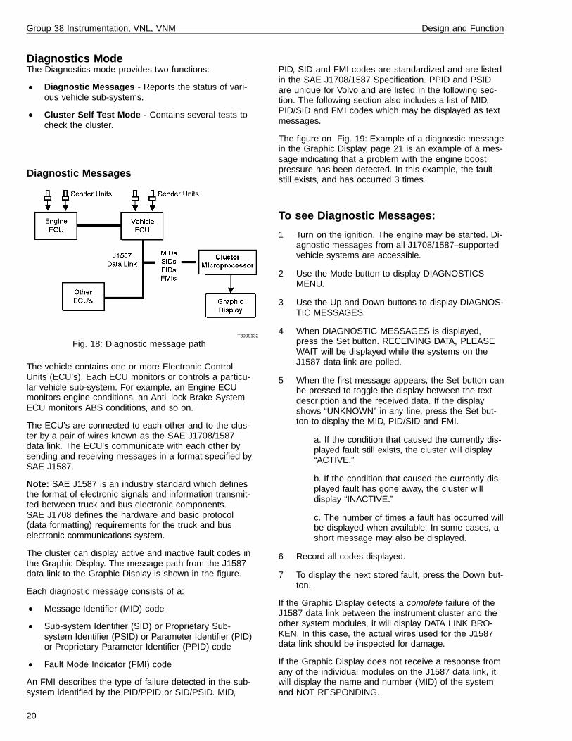
Fig. 18: Diagnostic message path
The vehicle contains one or more Electronic ControlUnits (ECU’s). Each ECU monitors or controls a particu-lar vehicle sub-system. For example, an Engine ECUmonitors engine conditions, an Anti–lock Brake SystemECU monitors ABS conditions, and so on.
The ECU’s are connected to each other and to the clus-ter by a pair of wires known as the SAE J1708/1587data link. The ECU’s communicate with each other bysending and receiving messages in a format specified bySAE J1587.
Note: SAE J1587 is an industry standard which definesthe format of electronic signals and information transmit-ted between truck and bus electronic components.SAE J1708 defines the hardware and basic protocol(data formatting) requirements for the truck and buselectronic communications system.
The cluster can display active and inactive fault codes inthe Graphic Display. The message path from the J1587data link to the Graphic Display is shown in the figure.
Each diagnostic message consists of a:
• Message Identifier (MID) code
• Sub-system Identifier (SID) or Proprietary Sub-system Identifier (PSID) or Parameter Identifier (PID)or Proprietary Parameter Identifier (PPID) code
• Fault Mode Indicator (FMI) code
An FMI describes the type of failure detected in the sub-system identified by the PID/PPID or SID/PSID. MID,
PID, SID and FMI codes are standardized and are listedin the SAE J1708/1587 Specification. PPID and PSIDare unique for Volvo and are listed in the following sec-tion. The following section also includes a list of MID,PID/SID and FMI codes which may be displayed as textmessages.
The figure on Fig. 19: Example of a diagnostic messagein the Graphic Display, page 21 is an example of a mes-sage indicating that a problem with the engine boostpressure has been detected. In this example, the faultstill exists, and has occurred 3 times.
To see Diagnostic Messages:
1 Turn on the ignition. The engine may be started. Di-agnostic messages from all J1708/1587–supportedvehicle systems are accessible.
2 Use the Mode button to display DIAGNOSTICSMENU.
3 Use the Up and Down buttons to display DIAGNOS-TIC MESSAGES.
4 When DIAGNOSTIC MESSAGES is displayed,press the Set button. RECEIVING DATA, PLEASEWAIT will be displayed while the systems on theJ1587 data link are polled.
5 When the first message appears, the Set button canbe pressed to toggle the display between the textdescription and the received data. If the displayshows “UNKNOWN” in any line, press the Set but-ton to display the MID, PID/SID and FMI.
a. If the condition that caused the currently dis-played fault still exists, the cluster will display“ACTIVE.”
b. If the condition that caused the currently dis-played fault has gone away, the cluster willdisplay “INACTIVE.”
c. The number of times a fault has occurred willbe displayed when available. In some cases, ashort message may also be displayed.
6 Record all codes displayed.
7 To display the next stored fault, press the Down but-ton.
If the Graphic Display detects a complete failure of theJ1587 data link between the instrument cluster and theother system modules, it will display DATA LINK BRO-KEN. In this case, the actual wires used for the J1587data link should be inspected for damage.
If the Graphic Display does not receive a response fromany of the individual modules on the J1587 data link, itwill display the name and number (MID) of the systemand NOT RESPONDING.
20

Group 38 Instrumentation, VNL, VNM Design and Function
W3002707
Fig. 19: Example of a diagnostic message in the Graphic Display
Graphic Display Messages
MID’s (Message ID’s orsources)
Description
128 Engine
232 SRS (Airbag)
136 ABS
140 Instrument
144 Cab Controller
130 Transmission
PID’s (Parameter ID’s) Description
84 Road speed
91 % Throttle pedal
100 Engine oil pressure
102 Boost pressure
105 Air inlet temperature
110 Engine coolant temp
111 Coolant level
175 Engine oil temperature
190 Engine speed
21

Group 38 Instrumentation, VNL, VNM Design and Function
PPID’s (Proprietary ParameterID’s)
Description
69 Buffered idle switch
70 Pedal switches, supply
71 Cruise control and retarder, supply switch
72 Accelerator pedal and retarder, supply sensors
73 Accelerator control 2 and primary tank, supply sensors
75 Range inhibitor, status solenoid valve
76 Brake lamps, status relay
77 Compressor, status solenoid valve
78 Interval wiper, status relay
79 Area inhibitor, status solenoid valve
86 Engine brake torque percent
109 EPG3 drive stage failure
121 MTE (Engine compressor control output) failure
122 VCB Engine compression brake
123 EPG2 Start and Warmhold
124 EPG1 Engine brake
125 EOL Enable failure
195 Proprietary Diagnostic Data Request/Clear Count
196 Proprietary Diagnostic Data/Count Clear Response
Common SID’s (SubsystemID’s)
Description
242 CC resume switch
243 CC set switch
244 CC enable switch
245 Clutch pedal switch
246 Brake pedal switch #1
247 Brake pedal switch #2
251 Power supply
22

Group 38 Instrumentation, VNL, VNM Design and Function
Engine SID’s (SubsystemID’s)
Description
1 Injector #1
2 Injector #2
3 Injector #3
4 Injector #4
5 Injector #5
6 Injector #6
21 Engine position sensor
22 Timing sensor
25 Ext. Engine protection sig.
PSID’s (Proprietary Subsys-tem ID’s)
Description
PSID 1 Retarder Brake Control Set Switch
PSID 2 Idle Validation Switch #2
PSID 3 Idle Validation Switch #3
PSID 4 Retarder Brake Control Switch
Brake SID’s (Subsystem ID’s) Description
1 ABS Snsr axle 1 L
2 ABS Snsr axle 1 R
3 ABS Snsr axle 2 L
4 ABS Snsr axle 2 R
5 ABS Snsr axle 3 L
6 ABS Snsr axle 3 R
7 ABS valve axle 1 L
8 ABS valve axle 1 R
9 ABS valve axle 2 L
10 ABS valve axle 2 R
11 ABS valve axle 3 L
12 ABS valve axle 3 R
13 ABS rtrdr ctrl relay
18 ABS, dif 1 - ASR valve
Airbag SID’s (Subsystem ID’s) Description
1 Dr Airbag lgn Loop
23

Group 38 Instrumentation, VNL, VNM Design and Function
FMI’s (Failure Modes) Description
0 Data valid, but high
1 Date valid, but low
2 Data erratic
3 Voltage shorted high
4 Voltage shorted low
5 Current low or open C
6 Current high or short C
7 Mech syst no respons
8 Abnormal freq or PW
9 Abnormal update rate
10 Abnormal change rate
11 Failure unknown
12 Bad device
13 Out of calibration
14 Special instruction (see Note)
A complete list of MIDs, PIDs, SIDs and FMIs is pub-lished in the SAE J1708/1587 document
Note: The special instruction FMI #14 is broadcast whenthe airbag has stored crash data.
24

Group 38 Instrumentation, VNL, VNM Design and Function
Cluster self-test modeAs an aid in troubleshooting the cluster, the cluster self-test mode provides the following tests:
Note: While in the cluster self-test mode, the EngineECU data link is disconnected. Therefore the gauges willnot function until the cluster is out of the self-test mode.
• Bulb test - Turns on all telltale indicators, and redwarning LEDs in the gauges which have them, forten seconds.
Note: The gauges in the instrument cluster are notfunctional during the bulb test. The ignition key canbe cycled off and on to interrupt any test.
• Gauge test - This causes the pointers in theTachometer, Speedometer, Oil PSI, Coolant Tem-perature, Fuel, and Turbo Boost gauges to sweepfrom minimum scale to full scale and back, brieflystopping at mid-scale each way. This occurs threetimes. The pyrometer, axle temperature and airpressure gauges are excluded from the self test.Cycle the ignition key off and on after the gauge testto return the gauges to normal function.
Note: Each time power is applied to the cluster, thespeedometer and tachometer pointers return tozero, taking the shortest path (usually counter-clockwise). If (during shipment, for example) thepointers are at the high end of their scales, they willmove clockwise toward zero when power is applied,and will be prevented from reaching zero by thegauge housing. In this case, use the Gauge Testfunction to return the tachometer and speedometerpointers counter-clockwise to zero.
• Display test - To help identify defects in the GraphicDisplay, the display will alternate between all darkand all light for about 10 seconds:
W3000719
Fig. 20:
• Buzzer test - Sounds each of the three buzzer sig-nals for 10 seconds each.
1 To access the Cluster Self Test:
2 Use the Mode button to display DIAGNOSTICSMENU.
3 Press the Up or Down button to scroll toCLUSTER SELF TEST MODE.
4 Press the Set button to activate the Cluster SelfTest mode.
5 Press the Up or Down button to display the de-sired test name (Bulb Test, Gauge Test, DisplayTest, or Buzzer Test).
6 Press the Set button to begin the displayed test.The test will end automatically.
25

Group 38 Instrumentation, VNL, VNM Design and Function
Set-up ModeThe Set-up mode allows the driver to choose betweenEnglish or metric units, between 12- or 24-hour time,and to set the Graphic Display contrast, the Graphic Dis-play and odometer brightness, and (optionally) to set afuel economy target value.
Settings are retained when the ignition is off, and alsowhen the battery is disconnected. If battery power is lostwhile in the Set-Up mode, the instrument cluster will goback to its default values.
UnitsThe units function configures the cluster to display datain the English or metric mode.
• English - Distances are displayed in miles, temper-atures are displayed in Fahrenheit degrees, andFuel Economy is displayed in miles per gallon.
• Metric - Distances are displayed in kilometers, tem-peratures are displayed in Celsius degrees, andFuel Economy is displayed in liters per kilometer.
To configure the cluster for English or metric:
1 Use the Mode button to display SET UP MENU.
2 Press the Up or Down button to scroll to UNITS.
3 Use the Set button to toggle between ENGLISH andMETRIC.
Clock ModeThe clock mode configures the clock to display 12-hour(am/pm) or 24-hour time. To change the clock format:
1 Use the Mode button to display SET UP MENU.
2 Press the Down button to scroll to CLOCK MODE.
3 Use the Set button to toggle between the 12- and24-hour formats.
Contrast AdjustThis function adjusts the contrast of the Graphic Display.To adjust the display contrast level, do the following:
1 Use the Mode button to display SET UP MENU.
2 Use the Down button to scroll to CONTRAST AD-JUST.
3 Press the Set button.
4 Use the Up and Down buttons to increase or de-crease the contrast.
5 When the contrast is at the desired level, press theSet button. (If you do not press the Set button here,
the setting won’t be saved — the setting will remainin effect until the ignition is turned off and will returnto its previous setting when the ignition is turnedback on.)
6 Press the Mode button to return to the SET-UPMENU display.
Backlighting AdjustThis function allows the odometer and graphic displaybacklighting (brightness) to be adjusted independently ofthe gauge backlighting. To adjust the backlighting, do thefollowing:
Note: Marker lights must be on to adjust the backlighting.
1 Use the Mode button to display SET UP MENU.
2 Press the Down button to scroll to BACKLIGHTINGADJUST.
3 Press the Set button.
4 Use the Up and Down buttons to increase or de-crease the backlighting.
5 When the backlighting is at the desired level, pressthe Set button. (If you do not press the Set buttonhere, the setting won’t be saved — the setting willremain in effect until the ignition is turned off andwill return to its previous setting when the ignition isturned back on.)
6 Press the Mode button to return to the SET-UPMENU display.
Fuel Economy Target AdjustThis function allows a fuel economy target to be set. Tochange the fuel economy target value, do the following:
1 Use the Mode button to display SET-UP MENU.
2 Press the Down button to scroll to FUEL ECON-OMY TARGET.
3 Press the Set button.
4 Use the Up and Down buttons to increase or de-crease the desired value.
5 When the desired value is displayed, press the Setbutton. (If you do not press the Set button here, thesetting won’t be saved — the setting will remain ineffect until the ignition is turned off and will return toits previous setting when the ignition is turned backon.)
6 Press the Mode button to return to the SET-UPMENU display.
26

Group 38 Instrumentation, VNL, VNM Design and Function
Gauge ModeThe Gauge mode provides additional gauge displays. Avoltage display is standard. Engine oil temperature andtransmission oil temperature displays are optional andare enabled by End-of-Line programming. Gauge dis-plays contain a symbol and a value (such as volts ordegrees), and text messages when appropriate.
T3009133
Fig. 21: Gauge displays
Note: When a condition requiring attention occurs, thesymbol identifying that condition will automatically re-place the current gauge display.
To choose a gauge display:
1 Press the Mode button until a gauge display ap-pears.
2 Use the Up and Down buttons to display the desiredgauge:
• Voltmeter - This standard gauge display moni-tors the battery voltage. If the voltage goesbelow 11.8 volts, TOO LOW will be displayed.
• Engine Oil Temperature - The range of thisoptional gauge display is 32–155�C (90–310�F).If the temperature exceeds the trip point, TOOHIGH will be displayed and the yellow Cautiontelltale will light.
• Transmission Oil Temperature - This optionalgauge display monitors the transmission oiltemperature. Its range is 32–155�C (90–310�F).If the temperature exceeds the trip point, HIGHwill be displayed and the yellow Caution telltalewill light.
Preset Trip Points for Graphic DisplayGaugesEach of the gauges in the Graphic Display has a presettrip point. A trip point represents a critical condition whenreached. The Engine Oil Temperature gauge displaymay have a trip point of 270�F, for example. Should a trippoint be reached, the Graphic Display will automaticallyreplace the current gauge display (or any other display,for that matter) with a symbol or message identifying thecritical condition.
Trip points for clusters to be used with Volvo engines arepreset at the factory during End-of-Line programming.When the cluster is installed with a Caterpillar, Cum-mins, or Detroit Diesel engine, the trip points are sentvia the J1587 data link according to each manufacturer’sspecifications. Refer to the appropriate manual for thesetrip points.
In some cases, the yellow Caution telltale or red Stop
telltale may also light, and the buzzer may also soundwhen a trip point is reached. These warnings will con-tinue until the ignition is turned off or until the conditioncausing the warning no longer exists. The visual and au-dible warnings will return if the condition that caused thewarning still exists when the ignition is turned back on.
Fuel Economy ModeThe Fuel Economy mode allows the driver to see his fueleconomy during a trip. Information is updated continuallyand is presented in the form of a bargraph. Average fueleconomy during the trip (AVG), and the fuel economyunder the current conditions (INST) can be seen at aglance, along with the fuel economy target value (set us-ing the Set-Up menu).
The Fuel Economy mode contains a Avg/Inst/Target dis-play and a Trip Fuel Meter display function. To selectone of these displays:
1 Use the Mode button to select the Fuel Economydisplay.
2 Use the Up and Down buttons to display the bar-graph or TRIP FUEL METER.
Avg/Inst/Target Display
T3009007
Fig. 22:
The Avg/Inst/Target Display shows the vehicle’s average,instantaneous, and target fuel economy. The range is 0to 99.9 miles per gallon, or 0 to 999 liters per 100 kilo-meters (selectable using the Set-Up menu). The data iscalculated by the microprocessor on the Left CircuitBoard using inputs from the J1587 data link. The AVGvalue can be reset by pressing the Set button while inthis display (the Trip Fuel Meter value will also be reset).
Trip Fuel Meter
The Trip Fuel meter displays the amount of fuel usedsince the last time it was reset. Its range is from 0 to9999 gallons or liters (driver selectable), and the data iscalculated by the microprocessor on the Left CircuitBoard using inputs from the J1587 data link. The TripFuel value can be reset to zero by pressing the Set but-ton while in this display (the AVG fuel economy value willalso be reset).
27

Group 38 Instrumentation, VNL, VNM Design and Function
Center Section
TachometerThe tachometer is an electrical aircore meter movementdriven by signals from the J1587 data link. In the ab-sence of data link information, the gauge pointer willmove to its minimum reading after a 3–5 second delay.
T3009008
Fig. 23:
Speedometer and OdometerThe speedometer is an electrical aircore meter move-ment driven by signals from the J1587 data link. In theabsence of data link information, the gauge pointer willmove to its minimum reading after a 3–5 second delay.Note that the cluster does not perform speedometer cali-bration. Speedometer calibration to compensate for tiresizes and other driveline changes is done duringprogramming of the engine ECU, vehicle ECU or trans-mission ECU.
The Odometer is a Liquid Crystal Display (LCD)mounted behind the speedometer dial. It has a full scalereading of 999999.9. Odometer information is calculatedfrom road speed via the J1587 data link and is stored inthe cluster’s microprocessor. The odometer backlightingcan be adjusted independently of gauge backlighting.
During normal operation, the odometer display goesblank 30 seconds after the ignition is switched off. To re-activate the display, turn the ignition on, or the odometerdisplay can be reactivated by pressing any of the buttons.
In the absence of speedometer data, the odometer dis-play will not change and the speedometer pointer willremain at zero.
W3000844
Fig. 24:
28

Group 38 Instrumentation, VNL, VNM Design and Function
Telltale Lamps, Center Section
W3002562
Fig. 25:
1 Left Turn Indicator2 5th Wheel Lock Indicator3 Wheel Differential Lock Indicator4 Interaxle Differential Lock Indicator5 High Beam Indicator6 Safety Belt Indicator7 SRS (Airbag) Indicator
8 Parking Brake Indicator9 Anti-Lock Brake System (Tractor) Indicator10 Anti-Lock Brake System (Trailer) Indicator11 Air Suspension System Indicator12 Bogie Lift Indicator13 Mirror Defroster Indicator14 Right Turn Indicator
Note that all gauges and telltales may not be used in allvehicles.
Master Warning telltaleA red Master Warning telltale consisting of an exclama-tion point (!) inside a triangle is located near the bottomand midway between the tachometer and the speedome-ter. It lights when the front or rear brake air pressure istoo low for safe operation (below 496 kPa (72 psi)).
W3000638
Fig. 26:
29

Group 38 Instrumentation, VNL, VNM Design and Function
Right Section
Forward and Rear Drive Axle Temperature (optional)The forward and rear axle temperature gauges are elec-trical aircore meter movements. They are connected totemperature sender units mounted on the axle housings.The higher the temperature, the lower the resistance ofthe sender unit, and the farther the gauge pointer movesto the right.
T3009009
Fig. 27: Forward Axle Temperature Gauge
Fuel LevelThe fuel level gauge is an electrical aircore meter move-ment that receives its signal from a sensor in the fueltank.
The fuel level sensor signal is input to the cluster micro-processor through the left module connector. In themicroprocessor the signal is changed from a resistanceto a pulse width modulated signal. It is then sent to theright module via a jumper (IPJ5). As the duty cycle ofthe signal increases, the level shown on the gauge in-creases.
W3001307
Fig. 28:
Application Air Pressure (optional)The application air pressure gauge is a mechanicalgauge. It is attached to the service brake system by ahose going into a quick-disconnect fitting on the rear ofthe gauge. It reads applied air pressure to the servicebrake system. The air hoses and quick-disconnects arecolor-coded to avoid wrong connections.
W3000608
Fig. 29:
30

Group 38 Instrumentation, VNL, VNM Design and Function
Front and Rear Brake Air PressureThe air pressure gauges are mechanical gauges. Theyare attached to their air systems by a hose going into aquick-disconnect fitting on the rear of the gauge. The airhoses and quick-disconnects are color-coded to avoidwrong connections.
The front and rear brake air pressure gauges containmechanical contacts. When the air pressure drops belowa preset value, the contacts close, causing a warningbuzzer to sound and a red warning LED in the lowerright corner of the gauge to light. The Master Warningindicator will also light.
W3000609
Fig. 30: Front Brake Air Pressure Gauge
Air Suspension Pressure (optional)The air suspension pressure gauge is a mechanicalgauge. It is attached to the air suspension system by ahose going into a quick-disconnect fitting on the rear ofthe gauge. It reads air pressure in the air suspensionsystem. The air hoses and quick-disconnects are color-coded to avoid wrong connections. W3002706
Fig. 31:
Telltale Lamps, Right Section
T3009010
Fig. 32:
1 Traction Control System2 APADS (Air Conditioning Protection and Diagnostic System — for future use)
Note that all gauges and telltales may not be used in allvehicles.
31

Group 38 Instrumentation, VNL, VNM Design and Function
Buzzer signalsThe buzzer is part of the cluster and has the following distinct signals:
• Turn signal - Single short beep in time with the Turn Indicator telltales.
• Clock reminder - A double beep every other second. This is activated by thealarm clock function in the Graphic Display and works whether the ignition is on oroff. The clock reminder will override a Turn signal buzzer.
• Warning signal - Two beeps every second. This is activated when any red telltaleexcept No Charge, Park Brake and Seat Belt are on and the engine is runningfaster than 95 rpm (idle). The Warning signal will override all other signals.
While in the cluster self test or diagnostic mode the buzzers do not sound.
32

Group 38 Instrumentation, VNL, VNM Design and Function
Connector Pinouts
LX and LY Connectors
W3000849
Fig. 33:
Left Module, LX Connector
Pin Description Circuit No. Input
1 Data Link + (J1587) 400 mV reading
2 Fuel Sensor 183 33-250 ohms
3 Fuel Level (Jumper to Right Module) IPJ5 Pulse width modu-lated signal (5V)
5 Mode button
6 Down button
7 Set button
9 Battery - 0X-1 Ground
10 Battery + 202 +12 V
11 Data Link - (J1587) 401 mV reading
12 Power Ground 0P-1 Ground
16 Up button
20 Illumination + 141-J 0-12 V
21 Switch buttons’ reference
22 Ignition + 180 +12 V
Pins not listed are not used. Note: All resistance measurements must be made withpower removed from the circuit.
33

Group 38 Instrumentation, VNL, VNM Design and Function
Left Module, LY Connector
Pin Description Circuit No. Input
1 Air Filter Restriction Gauge 199 Ground (when acti-vated)
3 Bulb Test + (Output) (Jumper to Center Module) IPJ1 +12V during bulb test
4 Bulb Test - (Output) (Jumper to Center Module) IPJ2 Ground during bulbtest
5 No Charge Warning Lamp 14 Ground (Note 1)
6 Stop Engine Warning Lamp (Caterpillar, Cumminsand Detroit Diesel engines only. Volvo is not hard-wired.)
575 Ground
10 Caution Lamp 576 Ground (Note 2)
11 Engine Fluids Warning Lamp (Volvo and Cumminsengines only)
577 Ground
13 Pyrometer - 190 Ground
15 + 5V Output (Reference Jumper to Right Module) IPJ3 +5V
16 Return to Zero (Jumper to Right Module) IPJ4 Ground
19 End Of Line Programming Enable 403A Ground (used onlywhen programming)
23 Washer Fluid Level 387A Ground (when acti-vated)
28 Transmission Oil Temperature 314 Sensor Input
30 Pyrometer + 191 0-100 mV
Pins not listed are not used.
All resistance measurements must be made with powerremoved from the circuit.
Note 1: The No Charge Warning Lamp will begin to illu-minate dimly when the engine is running and the inputon this pin drops below 12 V. It will illuminate fully whenit drops below 8 V.
Note 2: The Caution lamp illuminates when engine RPMis above 500, and there is a fault in the graphic displayfor Engine Oil Temperature, Transmission Oil Tempera-ture, or Voltage. The Caution lamp will also illuminate ifother Engine ECU fault codes instruct the lamp to illumi-nate.
34

Group 38 Instrumentation, VNL, VNM Design and Function
CY Connector
W3000765
Fig. 34:
Center Module, CY Connector
Pin Description CircuitNo.
Input
1 ABS, Truck 779 Ground
3 Park Brake 420 Ground
4 Heated Mirror 702 +12V
5 Bulb Test + (Jumperfrom LY-3)
IPJ1
6 Bulb Test - (Jumperfrom LY-4)
IPJ2
8 High Beam 33 +12V
9 Right Turn Indicator 113 +12V
10 Interaxle DifferentialLock
422 +12V
11 Power Ground 0P-3 Ground
12 Interwheel DifferentialLock
426 Ground
13 Fifth Wheel Lock 424 Ground
14 Left Turn Indicator 112 +12V
15 Air Suspension Pres-sure
431 Ground
18 Backlighting 141-H 0-12V
19 Bulb Test + (Jumper toRight Module)
IPJ6
20 Bulb Test - (Jumper toRight Module)
IPJ7
22 Ignition + 180 +1
24 SRS (Airbag) Warning 720 +12V (Willturn onalso if in-put circuitis open)
25 Master Warning(Jumper from RightModule)
IPJ8 Ground
Pins not listed are not used.
All resistance measurements must be made with powerremoved from the circuit.
35

Group 38 Instrumentation, VNL, VNM Design and Function
RX Connector
W3000847
Fig. 35:
Right Module, RX Connector
Pin Description Circuit No. Input
1 Illumination + 141-G 0-12 V
2 Ground 0X-2 Ground
3 Rear Axle Temperature (Front) 468 Variable resistance(Note 1)
4 Fuel Level (Jumper from LX-3, Left Module) IPJ5 Pulse width modu-lated signal
7 Master Warning output (Jumper to Center Module) IPJ8 Ground
11 Power Ground 0P-4 Ground
12 +5V (Jumper from LY-15, Left Module) IPJ3 +5 V
13 Rear Axle Temperature (Rear) 469 Variable resistance(Note 1)
14 Ignition + 180 +12V
15 Return to Zero (Jumper from LY-16, Left Module) IPJ4 Ground
18 Bulb Test + (Input) (Jumper from Center Module) IPJ6 +12V during bulb test
19 Bulb Test - (Input) (Jumper from Center Module) IPJ7 Ground during bulbtest
21 Traction Control System 774-B (Bendix)774-A (Wabco)
Ground
Pins not listed are not used.
All resistance measurements must be made with powerremoved from the circuit.
Note 1: Axle temperature measurements must be madewith the RX connector disconnected.
36

Group 38 Instrumentation, VNL, VNM Troubleshooting
Troubleshooting
Instrumentation Troubleshooting
CAUTION
Before starting a procedure, see “General Work Prac-tices” page 3 for general safety precautions whenworking with the instrument cluster. Failure to followthe safety precautions may result in instrument clusterdamage.
General Service InformationMany of the components can be tested without disturb-ing the cluster by using the Cluster Self Test Modefunction in the Graphic Display’s Diagnostics Menu. Thisincludes all telltale lamps, the speedometer, tachometer,oil pressure gauge, coolant temperature gauge andGraphic Display unit. The pivot-down mounting feature ofthe cluster allows troubleshooting of input signals withoutremoving the cluster from the vehicle.
Note: Individual gauges in the center and left modules ofthe VN instrument cluster are not serviceable during thewarranty period. Attempts to service or replace indi-vidual gauges during the warranty period will voidthe cluster warranty. Instead, the whole unit may beexchanged.ONLY when a trained technician is changing the configu-ration of a replacement instrument cluster may the leftside of the cluster be opened during the warranty period.
Storing the Cluster
CAUTION
When servicing or troubleshooting, do not leave thecluster face-down for more than 15 minutes, ordamage to the gauges may occur. Gauge oil can runout the front of the gauge faces and make the gaugesinaccurate. For this reason, always store clusters andgauges face-up.
Tools and Test EquipmentFor the procedures described in this chapter, you willneed the following tools:
• T25 Torx head driver (cluster mounting screws).• Telltale lamp removal tool (Volvo P/N 1608077)• Digital multi-meter which can measure down to 5
millivolts
Hose connections to the air pressure gauges arequick-disconnect and the air hoses to them can be dis-connected and reconnected without tools.
Never disconnect an air system component unless allsystem pressure has been depleted. Failure to de-plete system pressure before disconnecting hoses orcomponents may result in them separating violentlyand causing serious bodily injury.
37

Group 38 Instrumentation, VNL, VNM Troubleshooting
Troubleshooting Notes
For All Gauges:The gauge pointer can appear to be stuck out of range,either in the right or left lower corner. This may becaused by loss of power when the gauge pointer is pastthe halfway mark (to the right of center).
If the gauge pointer is stuck in one of the lower corners,do the following:Using the instrument cluster’s graphic display, selectCluster Self-Test Mode, then select Gauge Test.
The Gauge Test will drive all the data link gauges:
• coolant temperature• oil pressure• turbo• speedometer• tachometer
During the test, the pointer sweeps across the full rangeof the gauge, and back to the lowest point on the gauge.It should sweep the pointers 3 times.
A gauge pointer which appears to be sticking should bereturned to its normal position during the Gauge Test. Ifnot, repeat the Gauge Test one more time.
Note: Pointer width should be taken into account for allaccuracy checks. The width of the pointer, as well as theangle of viewing the pointer, can make the gauge appearto be inaccurate.
• Use the center line of the pointer — not the edge —as the reading.
• ALWAYS be directly in front of the gauge whenchecking accuracy. Looking at the gauge from theside will not provide a true reading (see figure).
W3001609
Fig. 36: Example of pointer out-of-range locations
W3002305
Fig. 37:
1 Reading of 20 from directly in front of thegauge
2 Reading of 20 from a side view
38
Group 38 Instrumentation, VNL, VNM Troubleshooting
Gauges, Troubleshooting
CAUTION
Before starting this procedure, see “General WorkPractices” page 3 for general safety precautions whenworking with the instrument cluster. Failure to followthe safety precautions may result in instrument clusterdamage.
Graphic DisplayUse the Display Test function in the Cluster Self TestMode of the Diagnostics Menu to test the graphic dis-play. If the display is defective, replace the instrumentcluster (if the cluster is out of warranty, the display maybe replaced separately).
During the Display Test, all pixels in the display will alter-nate from dark to light 2 times.
W3000719
Fig. 38:
Check for missing pixels, and for pixels that are alwaysdark. If defective, replace the cluster.
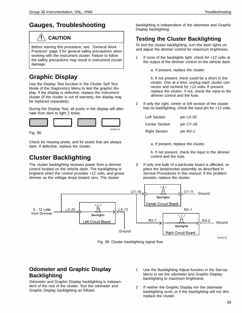
Cluster BacklightingThe cluster backlighting receives power from a dimmercontrol located on the vehicle dash. The backlighting isbrightest when the control provides +12 volts, and growsdimmer as the voltage drops toward zero. The cluster
backlighting is independent of the odometer and GraphicDisplay backlighting.
Testing the Cluster BacklightingTo test the cluster backlighting, turn the dash lights onand adjust the dimmer control for maximum brightness.
1 If none of the backlights light, check for +12 volts atthe output of the dimmer control on the vehicle dash.
a. If present, replace the cluster.
b. If not present, there could be a short in thecluster. One at a time, unplug each cluster con-nector and recheck for +12 volts. If present,replace the cluster; if not, check the input to thedimmer control and the fuse.
2 If only the right, center or left section of the clusterhas no backlighting, check the input pin for +12 volts.
Left Section pin LX-20
Center Section pin CY-18
Right Section pin RX-1
a. If present, replace the cluster.
b. If not present, check the input to the dimmercontrol and the fuse.
3 If only one bulb of a particular board is affected, re-place the lamp/socket assembly as described inService Procedures in this manual. If the problempersists, replace the cluster.
W3000716
Fig. 39: Cluster backlighting signal flow
Odometer and Graphic DisplayBacklightingOdometer and Graphic Display backlighting is indepen-dent of the rest of the cluster. Test the odometer andGraphic Display backlighting as follows:
1 Use the Backlighting Adjust function in the Set-UpMenu to set the odometer and Graphic Displaybacklighting to maximum brightness.
2 If neither the Graphic Display nor the odometerbacklighting work, or if the backlighting will not dim,replace the cluster.
39

Group 38 Instrumentation, VNL, VNM Troubleshooting
Buzzer ProblemsThe buzzer can be tested by performing the Buzzer Testin the Cluster Self Test Mode of the Diagnostics Menu.
The buzzer is not serviceable. If it fails to sound, replacethe cluster.
Buzzer Signal
Turn signal beep (momentary beep)
Clock reminder (double beep every other second)
Warning signal (two beeps every second)
Telltale Indicators
W3000986
Fig. 40: Telltale bulb signal flow
Telltale indicators are lighted by bulbs positioned acrossthe bottom of the instrument cluster.
Testing the Telltale BulbsTest the telltale bulbs by using the Bulb Test function inthe Cluster Self Test Mode of the Diagnostics menu.
1
CAUTION
When probing connector terminals, do not insertprobes into the terminals. This will spread the ter-minals apart, causing permanent damage. Probethe insertion side of the connector.
If none of the telltale bulbs light during the Bulb Testfunction, check for +12 volts between LY-3 and LY-4during the Bulb Test function. If missing, replace thecluster.
2 If the suspect bulb lights during the self test, theproblem is not in the cluster. Check the signalsource for individual telltale bulbs.
3 If the suspect bulb fails but other bulbs light duringthe self test, replace the suspect bulb.
4 If none of the bulbs in the center section light duringthe Bulb Test function, check for+12 volts between CY-5 and CY-6,or between CY-19 and CY-20.If missing, there is an open wire in the wiring har-ness.
5 If none of the bulbs in the right section light duringthe Bulb Test function, check for +12 volts betweenRX-18 and RX-19. If missing, there is an open wirein the wiring harness.
For more information, refer to the VNL, VNM ElectricalSchematics.
40

Group 38 Instrumentation, VNL, VNM Troubleshooting
Pyrometer Gauge
W3000870
Fig. 41: Pyrometer gauge signal flow
If the pyrometer thermocouple fails, the pointer will moveto one end of the dial or the other. A reading of 150�C(300�F) or less indicates an open in the truck’s wiring orthermocouple, and a reading of 815�C (1500�F) or moreindicates a short.
If the Pyrometer gauge fails to indicate within 100� F of aknown true value, check the thermocouple and wiringwith a digital voltmeter capable of reading down to 5 mil-livolts.
1 Make certain the vehicle ignition is OFF.
2
CAUTION
When servicing or troubleshooting, do not leavethe cluster face-down for more than 15 minutes,or damage to the gauges may occur. Gauge oilcan run out the front of the gauge faces andmake the gauges inaccurate.
CAUTION
When probing connector terminals, do not insertprobes into the terminals. This will spread the ter-minals apart, causing permanent damage. Probethe insertion side of the connector.
Gain access to the back of the cluster. With the igni-tion on, there should be 5 to 50 millivolts betweenconnector LY pins 30 and 13.
a. If the voltage is incorrect, replace the ther-mocouple or the wire to it.
b. If the voltage is correct, replace the cluster (ifthe cluster is out of warranty, the gauge may bereplaced separately).
41

Group 38 Instrumentation, VNL, VNM Troubleshooting
Engine Oil Pressure Gauge
W3002506
Fig. 42: Engine Oil Pressure gauge signal flow
In the absence of an engine oil pressure data signal, thegauge pointer will move to its minimum reading after a3–5 second delay.
If the pointers on all the gauges on the J1587 data busmove to the minimum reading, there is a problem in thedata link circuit. Troubleshoot the 400/401 wiring andconnectors.
Intermittent Function• If this and other gauges on the J1587 data link ap-
pear to “twitch” or function intermittently, check the400/401 circuit for a loose connection.
• If this gauge only appears to function intermittently,the data link could be overloaded with data fromECUs in the vehicle system. In this case, check thedata link using the MPSI Pro-Link Snapshot function.
Improper Gauge FunctionIf the gauge does not appear to function correctly, test itusing the Gauge Test function in the Cluster Self TestMode of the Diagnostics Menu, as follows. Also see “OilPressure Gauge Not Functioning” page 43 and “OilPressure Gauge Reads too Low” page 42.
1 If the gauge pointer sweeps back and forth acrossthe full range, the meter movement and its associ-ated circuitry in the cluster are working. Use theDiagnostic Messages function of the DiagnosticsMenu to check for oil pressure related messages.Use the service tool for the engine in your vehicle tocompare any diagnostic messages shown in the in-strument cluster.
2 If a sensor problem is indicated, check the wiringfrom the sensor for opens or shorts, according tothe engine manufacturer’s service literature. Also re-fer to the VNL, VNM Electrical Schematics for wiringinformation.
3 If the pointer fails to sweep, and a sensor problemhas been ruled out replace the cluster (if the clusteris out of warranty, the gauge may be replacedseparately).
Inaccurate Gauge ReadingUsing the Pro-link, check accuracy as follows. Startingwith a signal value of 60 psi, use the down arrow key todecrease to 30 psi. The gauge should read between 25and 35 (see figure). If there is a reading outside the 25and 35 markings, the gauge is faulty.
Note: Pointer width should be taken into account for allaccuracy checks. The width of the pointer, as well as theangle of viewing the pointer, can make the gauge appearto be inaccurate. Use the center line of the pointer — notthe edge — as the measurement. And ALWAYS be di-rectly in front of the gauge when checking accuracy.Looking at the gauge from the side will not provide atrue reading.
W3001055
Fig. 43: Acceptable range for input value of 30 psi
Oil Pressure Gauge Reads too Lowand there are NO sensor faults. If the cluster doesNOT have a Turbo PSI gauge, it is likely the OIL PSIgauge is configured to read Turbo pressure data. In thiscondition, the OIL PSI gauge will act like a Turbo gauge.This is a configuration error.
Solution: The Pro-Link with the Volvo Card (see Toolssection) can be used to check and correct configurationerrors.
1 If the cluster does NOT have a Turbo gauge:
2 Using the Pro-Link, go to Special Tests, and selectthe Turbo Gauge test.
W3001056
Fig. 44:
42
Group 38 Instrumentation, VNL, VNM Troubleshooting
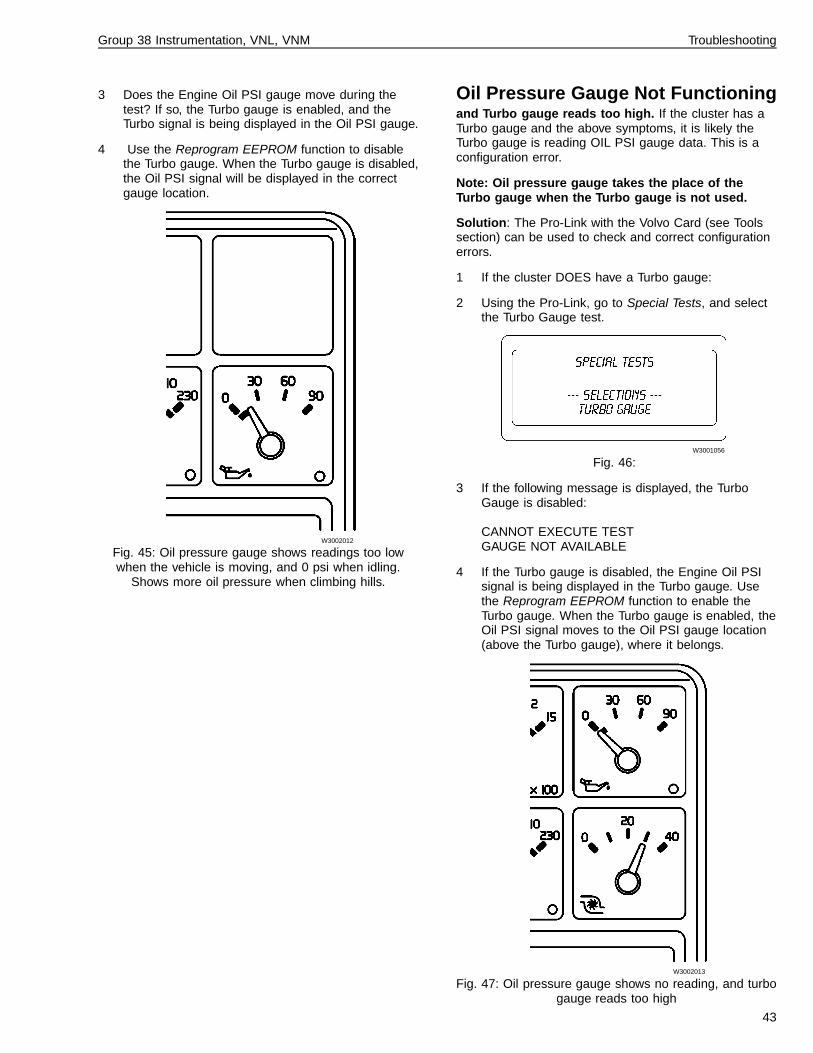
3 Does the Engine Oil PSI gauge move during thetest? If so, the Turbo gauge is enabled, and theTurbo signal is being displayed in the Oil PSI gauge.
4 Use the Reprogram EEPROM function to disablethe Turbo gauge. When the Turbo gauge is disabled,the Oil PSI signal will be displayed in the correctgauge location.
W3002012
Fig. 45: Oil pressure gauge shows readings too lowwhen the vehicle is moving, and 0 psi when idling.
Shows more oil pressure when climbing hills.
Oil Pressure Gauge Not Functioningand Turbo gauge reads too high. If the cluster has aTurbo gauge and the above symptoms, it is likely theTurbo gauge is reading OIL PSI gauge data. This is aconfiguration error.
Note: Oil pressure gauge takes the place of theTurbo gauge when the Turbo gauge is not used.
Solution: The Pro-Link with the Volvo Card (see Toolssection) can be used to check and correct configurationerrors.
1 If the cluster DOES have a Turbo gauge:
2 Using the Pro-Link, go to Special Tests, and selectthe Turbo Gauge test.
W3001056
Fig. 46:
3 If the following message is displayed, the TurboGauge is disabled:
CANNOT EXECUTE TESTGAUGE NOT AVAILABLE
4 If the Turbo gauge is disabled, the Engine Oil PSIsignal is being displayed in the Turbo gauge. Usethe Reprogram EEPROM function to enable theTurbo gauge. When the Turbo gauge is enabled, theOil PSI signal moves to the Oil PSI gauge location(above the Turbo gauge), where it belongs.
W3002013
Fig. 47: Oil pressure gauge shows no reading, and turbogauge reads too high
43
Group 38 Instrumentation, VNL, VNM Troubleshooting
Engine Coolant TemperatureGauge
W3000718
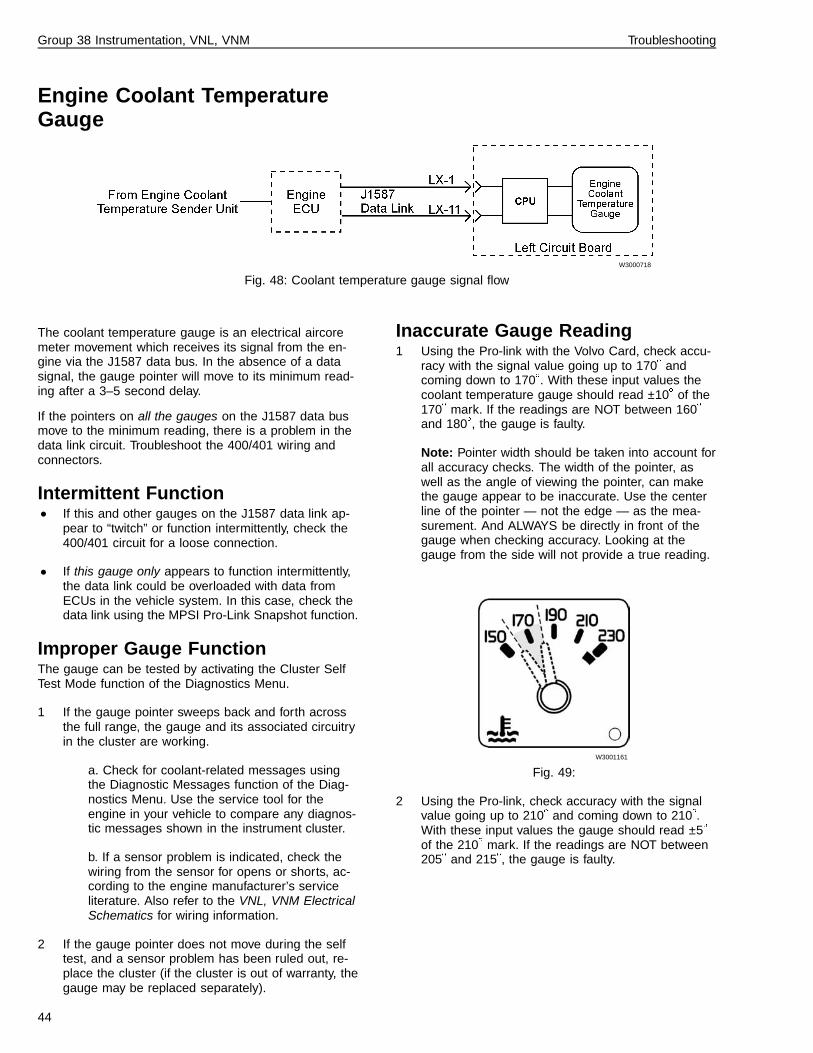
Fig. 48: Coolant temperature gauge signal flow
The coolant temperature gauge is an electrical aircoremeter movement which receives its signal from the en-gine via the J1587 data bus. In the absence of a datasignal, the gauge pointer will move to its minimum read-ing after a 3–5 second delay.
If the pointers on all the gauges on the J1587 data busmove to the minimum reading, there is a problem in thedata link circuit. Troubleshoot the 400/401 wiring andconnectors.
Intermittent Function• If this and other gauges on the J1587 data link ap-
pear to “twitch” or function intermittently, check the400/401 circuit for a loose connection.
• If this gauge only appears to function intermittently,the data link could be overloaded with data fromECUs in the vehicle system. In this case, check thedata link using the MPSI Pro-Link Snapshot function.
Improper Gauge FunctionThe gauge can be tested by activating the Cluster SelfTest Mode function of the Diagnostics Menu.
1 If the gauge pointer sweeps back and forth acrossthe full range, the gauge and its associated circuitryin the cluster are working.
a. Check for coolant-related messages usingthe Diagnostic Messages function of the Diag-nostics Menu. Use the service tool for theengine in your vehicle to compare any diagnos-tic messages shown in the instrument cluster.
b. If a sensor problem is indicated, check thewiring from the sensor for opens or shorts, ac-cording to the engine manufacturer’s serviceliterature. Also refer to the VNL, VNM ElectricalSchematics for wiring information.
2 If the gauge pointer does not move during the selftest, and a sensor problem has been ruled out, re-place the cluster (if the cluster is out of warranty, thegauge may be replaced separately).
Inaccurate Gauge Reading1 Using the Pro-link with the Volvo Card, check accu-
racy with the signal value going up to 170� andcoming down to 170�. With these input values thecoolant temperature gauge should read ±10� of the170� mark. If the readings are NOT between 160�
and 180�, the gauge is faulty.
Note: Pointer width should be taken into account forall accuracy checks. The width of the pointer, aswell as the angle of viewing the pointer, can makethe gauge appear to be inaccurate. Use the centerline of the pointer — not the edge — as the mea-surement. And ALWAYS be directly in front of thegauge when checking accuracy. Looking at thegauge from the side will not provide a true reading.
W3001161
Fig. 49:
2 Using the Pro-link, check accuracy with the signalvalue going up to 210� and coming down to 210�.With these input values the gauge should read ±5�
of the 210� mark. If the readings are NOT between205� and 215�, the gauge is faulty.
44

Group 38 Instrumentation, VNL, VNM Troubleshooting
W3002016
Fig. 50:
45

Group 38 Instrumentation, VNL, VNM Troubleshooting
Turbo Boost Pressure Gauge
W3000723
Fig. 51: Turbo Boost Pressure gauge signal flow
The Turbo Boost Pressure gauge is an electrical aircoremeter movement which receives its signal from the en-gine via the J1587 data bus. In the absence of a datasignal, the gauge pointer will move to its minimum read-ing after a 3–5 second delay. If Turbo Boost Pressuredata is missing during normal operating conditions, theTurbo Boost Pressure gauge pointer will move to the lowend of the scale (zero pressure).
If the pointers on all the gauges on the J1587 data busmove to the minimum reading, there is a problem in thedata link circuit. Troubleshoot the 400/401 wiring andconnectors.
Intermittent Function• If this and other gauges on the J1587 data link ap-
pear to “twitch” or function intermittently, check the400/401 circuit for a loose connection.
• If this gauge only appears to function intermittently,the data link could be overloaded with data fromECUs in the vehicle system. In this case, check thedata link using the MPSI Pro-Link Snapshot function.
Improper Gauge FunctionTo test the gauge:
1 Check for messages using the Diagnostic Messagesfunction of the Diagnostics Menu. Use the engineservice tool to compare any diagnostic messagesshown in the instrument cluster. If a sensor problemis indicated, check the wiring from the sensor foropens or shorts, according to the engine manufac-turer’s service literature. Refer to the VNL, VNMElectrical Schematics for wiring information. Alsosee “Turbo Gauge Reads too High” page 47.
2 Use the Gauge Test function in the Cluster Self TestMode of the Diagnostics Menu.
a. If the Turbo Boost Pressure gauge pointersweeps back and forth across its full range, its
meter movement and associated circuitry in thecluster are working.
b. If the gauge pointer does not move duringthe self test, and a sensor problem has beenruled out, replace the cluster (if the cluster isout of warranty, the gauge may be replacedseparately).
Inaccurate Gauge ReadingUsing the Pro-link, check accuracy with the signal valuegoing up to 20 psi. With this input value, the gaugeshould read between 15 and 25 psi (see figure). If thereis a reading outside 15 and 25, the gauge is faulty. Alsosee “Turbo Gauge Reads too High” page 47.
Note: Pointer width should be taken into account for allaccuracy checks. The width of the pointer, as well as theangle of viewing the pointer, can make the gauge appearto be inaccurate. Use the center line of the pointer — notthe edge — as the measurement. And ALWAYS be di-rectly in front of the gauge when checking accuracy.Looking at the gauge from the side will not provide atrue reading.
W3001054
Fig. 52:
46

Group 38 Instrumentation, VNL, VNM Troubleshooting
Turbo Gauge Reads too Highand Oil PSI gauge not functioning. If the cluster has aTurbo gauge and the above symptoms, it is likely theTurbo gauge is reading OIL PSI gauge data. This is aconfiguration error.
Note: Oil pressure gauge takes the place of theTurbo gauge when the Turbo gauge is not used.
Solution: The Pro-Link with the Volvo Card (see Toolssection) can be used to check and correct configurationerrors.
1 If the cluster DOES have a Turbo gauge:
2 Using the Pro-Link, go to Special Tests, and selectthe Turbo Gauge test.
W3001056
Fig. 53:
3 If the following message is displayed, the TurboGauge is disabled:
CANNOT EXECUTE TESTGAUGE NOT AVAILABLE
4 If the Turbo gauge is disabled, the Engine Oil PSIsignal is being displayed in the Turbo gauge. Usethe Reprogram EEPROM function to enable theTurbo gauge. When the Turbo gauge is enabled, theOil PSI signal moves to the Oil PSI gauge location(above the Turbo gauge), where it belongs.
W3002013
Fig. 54: Turbo gauge reads too high, and oil pressuregauge shows no reading
47

Group 38 Instrumentation, VNL, VNM Troubleshooting
Speedometer
W3000720
Fig. 55: Speedometer/Odometer/Tachometer signal flow
The speedometer gauge is an electrical aircore metermovement which receives its signal from the engine viathe J1587 data bus. In the absence of a data signal, thegauge pointer will move to its minimum reading after a3–5 second delay.
If the pointers on all the gauges on the J1587 data busmove to the minimum reading, there is a problem in thedata link circuit. Troubleshoot the 400/401 wiring andconnectors.
Intermittent Function• If this and other gauges on the J1587 data link ap-
pear to “twitch” or function intermittently, check the400/401 circuit for a loose connection.
• If this gauge only appears to function intermittently,the data link could be overloaded with data fromECUs in the vehicle system. In this case, check thedata link using the MPSI Pro-Link Snapshot function.
Improper Gauge Function /Calibra-tion CheckIf the speedometer accuracy is off, check the calibrationof the engine ECU (Vehicle ECU in vehicles with Volvoengines). Compare the results of the ECU calibrationwith readings obtained with the diagnostic service toolrecommended by the engine manufacturer.
Each engine manufacturer formats calibration differently.For the Volvo engine only, the ECU calibrates thespeedometer with the following formula:
pulses/mile = (tire rev/mile) x (rear axle ratio) x (no.of teeth on chopper wheel on transmission)
for example, pulses/mile = 501 rev/mi x 4.10 x 16pulses/rev = 32866 pulses/mile.
Test the speedometer by using the Gauge Test functionin the Cluster Self Test Mode of the Diagnostics Menu.Use the service tool for the engine in your vehicle tocompare any diagnostic messages shown in the instru-ment cluster. If a sensor problem is indicated, check thewiring from the sensor for opens or shorts, according tothe engine manufacturer’s service literature. Also refer to
the VNL, VNM Electrical Schematics for wiring informa-tion.
If the speedometer pointer sweeps back and forth acrossits full range, its meter movement and associated cir-cuitry within the cluster are working. If the gauge pointerdoes not move during the self test, and a sensor problemhas been ruled out, replace the cluster (if the cluster isout of warranty, the gauge may be replaced separately).
Inaccurate Gauge Reading1 Using the Pro-link 9000 and the Volvo card scroll to
the instrument cluster menu.
2 Press enter and scroll to Special Tests. Press enterand scroll to Speedo Gauge. Press enter again.
W3001203
Fig. 56:
3 Using the Pro-link, check accuracy with the signalvalue going up to 30 mph. With an input value of 30mph, the speedometer should read between 29 and33 mph (see figure). If there is a reading outside 29and 33 mph, the gauge is faulty.
W3001162
Fig. 57:
48

Group 38 Instrumentation, VNL, VNM Troubleshooting
Note: For some instrument clusters, with an inputvalue of 30 mph, the gauge should read between 29and 35 mph. These clusters have a stamp marked“STD” on the lower left side of the cluster (thisstamp can only be seen when the cluster is out ofthe dash).
Note: Pointer width should be taken into account forall accuracy checks. The width of the pointer, aswell as the angle of viewing the pointer, can makethe gauge appear to be inaccurate. Use the centerline of the pointer — not the edge — as the mea-surement. And ALWAYS be directly in front of thegauge when checking accuracy. Looking at thegauge from the side will not provide a true reading.
4 Using the Pro-link, check accuracy with the signalvalue going up to 55 mph. With an input value of 55
mph the speedometer should read between the 55and 58 mph marks (see figure). If there is a readingbelow 55 mph, or above 58 mph, the gauge is faulty.
W3002014
Fig. 58:
49

Group 38 Instrumentation, VNL, VNM Troubleshooting
Odometer
W3000720
Fig. 59: Speedometer/Odometer/Tachometer signal flow
During normal operation, the odometer display remainson for 30 seconds after the ignition is switched off. To re-activate the display, turn on the ignition or press theMode button.
In the absence of speedometer data, the odometer dis-play will not change and the speedometer pointer willremain at zero.
• If there is a problem with the odometer but thespeedometer works, replace the cluster (if the clus-ter is out of warranty, the gauge may be replacedseparately).
• The odometer should be accurate to ±0.3% of aknown measured distance. Do not compare the
odometer display to engine odometer data: the dis-play receives its input from the data link, but theengine receives its input directly from the wheelspeed sensors. Because these sources are differ-ent, the data received may be different also.
• If the odometer is inaccurate, check the engine ECUspeed calibration (Vehicle ECU in vehicles withVolvo engines). See “Improper Gauge Function/Calibration Check” page 48. If correct, the odome-ter is faulty.
50

Group 38 Instrumentation, VNL, VNM Troubleshooting
Tachometer
W3000720
Fig. 60: Speedometer/Odometer/Tachometer signal flow
In the absence of data link information, the tachometergauge pointer will move to its minimum reading after a3–5 second delay.
If the pointers on all the gauges on the J1587 data busmove to the minimum reading, there is a problem in thedata link circuit. Troubleshoot the 400/401 wiring andconnectors.
Intermittent Function• If this and other gauges on the J1587 data link ap-
pear to “twitch” or function intermittently, check the400/401 circuit for a loose connection.
• If this gauge only appears to function intermittently,the data link could be overloaded with data fromECUs in the vehicle system. In this case, check thedata link using the Pro-Link Snapshot function.
Improper Gauge FunctionTest the tachometer by using the Gauge Test function inthe Cluster Self Test Mode function of the DiagnosticsMenu. Use the service tool for the engine in your vehicleto compare any diagnostic messages shown in the in-strument cluster. If a sensor problem is indicated, checkthe wiring from the sensor for opens or shorts, accordingto the engine manufacturer’s service literature. Also referto the VNL, VNM Electrical Schematics for wiring infor-mation.
If the tachometer pointer sweeps back and forth acrossits full range, its meter movement and associated cir-cuitry within the cluster are working. If the gauge pointerdoes not move during the self test, and a sensor problemhas been ruled out, replace the cluster (if the cluster isout of warranty, the gauge may be replaced separately).
Inaccurate Gauge Reading1 Using the Pro-link, check accuracy with the signal
value going up to 1000 rpm. With this input thetachometer should read between 925 and 1075 rpm(see figure). If readings outside 925 and 1075 rpmare received, the gauge is faulty.
Note: Pointer width should be taken into account forall accuracy checks. The width of the pointer, as
well as the angle of viewing the pointer, can makethe gauge appear to be inaccurate. Use the centerline of the pointer — not the edge — as the mea-surement. And ALWAYS be directly in front of thegauge when checking accuracy. Looking at thegauge from the side will not provide a true reading.
W3001163
Fig. 61:
2 Using the Pro-link, check accuracy with the signalvalue going up to 2000 rpm. With this input thetachometer should read between 1925 and 2075rpm (see figure). If readings outside 1925 and 2075rpm are received, the gauge is faulty.
W3002015
Fig. 62:
51

Group 38 Instrumentation, VNL, VNM Troubleshooting
Axle Temperature Gauges (For-ward and Rear)
W3000715
Fig. 63: Front and Rear Drive Axle Temperature gaugesignal flow
Fault IndicationsA constant gauge reading of 32�C (90�F) or less can becaused by a defective sender unit or gauge, or an openwire between the cluster and the sender unit.
A constant reading of 130�C (270�F) or more can becaused by a defective gauge or sender unit, or by a wirethat is shorted to ground between the gauge and thesender unit.
Inaccuracies greater than 12�C (10�F) usually indicate adefective sender unit or gauge.
Testing the Axle TemperatureGauges1 Make certain the vehicle ignition is OFF.
2
CAUTION
When servicing or troubleshooting, do not leavethe cluster face-down for more than 15 minutes,or damage to the gauges may occur. Gauge oilcan run out the front of the gauge faces andmake the gauges inaccurate.
CAUTION
When probing connector terminals, do not insertprobes into the terminals. This will spread the ter-minals apart, causing permanent damage. Probethe insertion side of the connector.
Gain access to the rear of the instrument cluster.Disconnect connector RX and measure the resis-tance between harness pin 13 (Front Axle gauge) orpin 3 (Rear Axle gauge), and pin 11 (ground):
Axle Temp. Expected Reading
21�C (70�F) 1000 ohms ±10%
50�C (120�F) 430 ohms ±10%
95�C (200�F) 110 ohms ±10%
3 If the resistance readings are correct, reconnect theconnectors and turn the key on. There should bebattery voltage between connector RX pins 11 and14. If not, and the rest of the cluster works, the wirefrom RX-14 is probably open.
4 If the readings are off more than 10%, the senderunit should be checked. The sender is mounted onthe axle. Refer to the VNL, VNM Electrical Schemat-ics for wiring information.
52

Group 38 Instrumentation, VNL, VNM Troubleshooting
Air Pressure Gauges
W3000836
Fig. 64:
Note: The LED connector wires are not polarity-sensitive.
Inaccurate or erratic gauge readings are usually causedby dirt or other contamination in the gauge. The gaugesand their warning LEDs can be tested as shown.
Never disconnect an air system component unless allsystem pressure has been depleted. Failure to de-plete system pressure before disconnecting hoses orcomponents may result in them separating violentlyand causing serious bodily injury.
Air Gauge Test:
1 Drain the air pressure from both air systems.
2
W3000842
Remove the two screws at the top of the instrumentcluster and lay the cluster face-down on the steeringcolumn.
3
W3000834
Fig. 65:
1) Rear Brake Pressure Air Line (Red)2) Front Brake Pressure Air Line (Green)3) Application Air Pressure Air Line (Black)
Remove the air lines from the Front and Rear BrakeAir Pressure gauges.
4 Connect the air lines back into the opposite gauges,start the engine and build the air pressure in thesystems.
5 Compare the sweep of both gauges to see if theproblem still exists, or if the problem is now in theother gauge. If the problem is in the other gauge,troubleshoot the air line for a kink or restriction.
6 If the problem still exists in the same gauge, replacethe gauge.
Air Gauge LED Test
1 To test the red warning LED in the Front or RearBrake Air Pressure gauge, pump the brake pedalwhile the ignition is on (and engine is off) to lowerthe system air pressure. When the pressure dropsbelow 60 psi, the LED must light. If not, check theLED circuitry by using the Bulb Test function. If theLED does not light during the Bulb Test, replace thegauge.
2 Start the engine. When the air pressure rises above70 ±10 psi, the LED should turn off. If not, replacethe gauge.
53

Group 38 Instrumentation, VNL, VNM Troubleshooting
Fuel Level Gauge
W3000873
Fig. 66: Fuel level gauge signal flow
The Fuel Gauge is an electrical aircore meter movementthat receives its signal from a sensor in the fuel tank.This signal is input to the microprocessor on the instru-ment cluster, which drives the gauge.
If the fuel gauge is reading incorrectly, it can be testedby activating the Cluster Self Test Mode function of theDiagnostics Menu:
• If the pointer sweeps back and forth across its fullrange during the cluster self test, the meter and itsassociated circuitry in the cluster are working. Go tostep 1 below.
• If the pointer does not sweep during the clusterself test, the most likely cause is a defective FuelLevel gauge, or a wiring problem in the harness. Goto step 4.
• If the pointer does not sweep during the clusterself test AND the pointer:
falls below the empty markor constantly stays on the Full markor constantly stays on the 1/2 mark
Go to step 6.
1 Make certain the vehicle ignition is OFF.
2 If gauge failure is suspected, check for mechanicalfailure of the fuel level sender. If the sender is ingood physical condition, disconnect the connectorand measure resistance at the fuel level sender. Thereading should be between 33 and 240 ohms de-pending upon the fuel level in the tank (see Table A).
• If resistance is as shown in Table A, reconnectthe sender connector and proceed to step 3.
• If resistance is not as shown in Table A, replacethe fuel level sender.
Table A: Resistance Check
Fuel Level Expected Reading(at sender andLX-2 to LX-12)
Empty tank 240 ohms ±10%
1/4 tank 153 ohms ±10%
1/2 tank 103 ohms ±10%
3/4 tank 67 ohms ±10%
Full tank 33 ohms ±10%
3
CAUTION
When servicing or troubleshooting, do not leavethe cluster face-down for more than 15 minutes,or damage to the gauges may occur. Gauge oilcan run out the front of the gauge faces andmake the gauges inaccurate.
CAUTION
When probing connector terminals, do not insertprobes into the terminals. This will spread the ter-minals apart, causing permanent damage. Probethe insertion side of the connector.
Gain access to the back of the instrument cluster.Disconnect connector LX and use an ohmmeter tomeasure the resistance between pins 2 and 12 onthe harness connector (insertion side). The readingshould be between 33 and 240 ohms dependingupon the fuel level in the tank (see Table A for val-ues).
• If resistance is as shown in Table A, go to step4.
• If resistance is not as shown in Table A, checkthe connectors and wiring from the LX connec-tor to the fuel level sender. Refer to the VNL,
54

Group 38 Instrumentation, VNL, VNM Troubleshooting
VNM Electrical Schematics for wiring informa-tion.
55
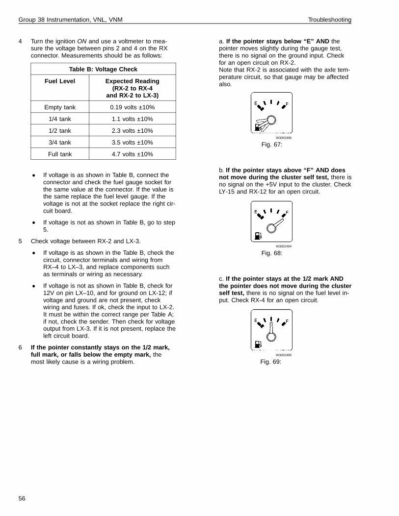
Group 38 Instrumentation, VNL, VNM Troubleshooting
4 Turn the ignition ON and use a voltmeter to mea-sure the voltage between pins 2 and 4 on the RXconnector. Measurements should be as follows:
Table B: Voltage Check
Fuel Level Expected Reading(RX-2 to RX-4
and RX-2 to LX-3)
Empty tank 0.19 volts ±10%
1/4 tank 1.1 volts ±10%
1/2 tank 2.3 volts ±10%
3/4 tank 3.5 volts ±10%
Full tank 4.7 volts ±10%
• If voltage is as shown in Table B, connect theconnector and check the fuel gauge socket forthe same value at the connector. If the value isthe same replace the fuel level gauge. If thevoltage is not at the socket replace the right cir-cuit board.
• If voltage is not as shown in Table B, go to step5.
5 Check voltage between RX-2 and LX-3.
• If voltage is as shown in the Table B, check thecircuit, connector terminals and wiring fromRX–4 to LX–3, and replace components suchas terminals or wiring as necessary.
• If voltage is not as shown in Table B, check for12V on pin LX–10, and for ground on LX-12; ifvoltage and ground are not present, checkwiring and fuses. If ok, check the input to LX-2.It must be within the correct range per Table A;if not, check the sender. Then check for voltageoutput from LX-3. If it is not present, replace theleft circuit board.
6 If the pointer constantly stays on the 1/2 mark,full mark, or falls below the empty mark, themost likely cause is a wiring problem.
a. If the pointer stays below “E” AND thepointer moves slightly during the gauge test,there is no signal on the ground input. Checkfor an open circuit on RX-2.Note that RX-2 is associated with the axle tem-perature circuit, so that gauge may be affectedalso.
W3002496
Fig. 67:
b. If the pointer stays above “F” AND doesnot move during the cluster self test, there isno signal on the +5V input to the cluster. CheckLY-15 and RX-12 for an open circuit.
W3002494
Fig. 68:
c. If the pointer stays at the 1/2 mark ANDthe pointer does not move during the clusterself test, there is no signal on the fuel level in-put. Check RX-4 for an open circuit.
W3002495
Fig. 69:
56

Group 38 Instrumentation, VNL, VNM Troubleshooting
Gauges, Troubleshooting (withPro-Link)
CAUTION
Before starting this procedure, see “General WorkPractices” page 3 for general safety precautions whenworking with the instrument cluster. Failure to followthe safety precautions may result in instrument clusterdamage.
Special Tests
The following tests require the Pro-Link 90001 and the Volvo card.
Low Eng Oil Prs Lamp This test activates the low engine oil pressure warning lamp.
Hi Cool Temp Lamp This test activates the high coolant temperature warning lamp and the display icon.
Caution Lamp/Icon This test activates the caution diagnostic telltale lamp and the associated displayicon.
Stop Eng Lamp/Icon This test activates the stop engine telltale lamp and the associated display icon.
Low Cool Level Warn This test activates the low coolant level display warning.
Hi Eng Oil Temp Warn This test activates the high engine oil temperature display warning.
Eng Oil Temp Gauge The engine oil temperature gauge can be driven in steps of ±10�F, from 50 to270�F. For this test to work, the gauge must be in the graphic display window.Gauge tolerance: ± 0.5�F
Preheat Status Icon This test activates the preheat display icon.
Speedometer The speedometer gauge can be driven in steps of ± 5 mph, from 0–80 mph.Gauge tolerance = +3 / –0 mph (Below 5 mph, tolerance = ± 3 mph).
Tachometer The tachometer gauge can be driven in steps of ±100 RPM, from 0–2500 RPM.Gauge tolerance = ± 50 RPM.
Cool Temp Gauge The coolant temp gauge can be driven in steps of ±5�F, from 150 to 230�F.Gauge tolerance:Above 190�F = ± 3.5�FBelow 190�F = ± 9�F
Eng Oil Prs Gauge The engine oil pressure gauge can be driven in steps of ±15 psi, from 0–90 psi.Gauge tolerance = ± 3 psi.
Turbo Boost Gauge The turbo boost pressure gauge can be driven in steps of ±5 psi, from 0–30 psi.Gauge tolerance = ± 3 psi.
Note: Gauge accuracy must be measured at room temperature (20–25�C (68-77�F)). The analog gauges have mag-netic characteristics which may change accuracy slightly over a long period of time.
Note: The tachometer will move to the 600 RPM mark during Special Tests. In vehicles with a Volvo engine, it is nor-mal for an audible beeping to occur during certain Special Tests. The engine must not be running during any SpecialTests, or the tests will not function.
1Pro-Link is a registered trademark of MPSI.
57

Group 38 Instrumentation, VNL, VNM Troubleshooting
View EEPROMClock Mode 12 or 24 hour mode
Turbo Gauge indicates whether the turbo gauge is in-stalled
Voltmeter indicates whether the voltmeter display is en-abled or disabled
Eng Oil Temp indicates whether the engine oil tempera-ture display is enabled or disabled
Trans Temp indicates whether the transmission oil temp.is enabled or disabled
Fuel Econ indicates whether the fuel economy feature isenabled or disabled
Hourmeter This displays the hourmeter total shown inthe instrument cluster.
Actual This displays the actual hourmeter total forthat particular instrument cluster. If the instrumentcluster has been reprogrammed to display a differ-ent total, this will show the actual total for thatinstrument cluster — not the reprogrammed total.
Odometer This displays the odometer total shown in theinstrument cluster.
Actual This displays the actual odometer total forthat particular instrument cluster. If the instrumentcluster has been reprogrammed to display a differ-ent total, this will show the actual total for thatinstrument cluster — not the reprogrammed total.
The last line of the View EEPROM menu will show theserial number of the last MPSI tool used to reprogramthe instrument cluster.
Reprogram EEPROMNote: When the Reprogram mode is entered, the serialnumber of the MPSI tool in use is recorded in the instru-ment cluster memory.
Note: There are no password-protected read/writefunctions
Clock Mode set 12 or 24 hour mode
Turbo Gauge enable or disable
Voltmeter enable or disable
Eng Oil Temp enable or disable
Trans Temp enable or disable
Fuel Econ enable or disable
Hourmeter This allows the hourmeter total to bechanged. It is used when installing a new instrumentcluster into a vehicle which already has miles on the en-gine.
Odometer This allows the odometer total to be changed.It is used when installing a new instrument cluster into avehicle which already has miles on it.
58

Group 38 Instrumentation, VNL, VNM Service Procedures
Service Procedures
59

Group 38 Instrumentation, VNL, VNM Service Procedures
Warranty NoticeNote: Individual gauges in the center and left modules ofthe VN instrument cluster are not serviceable during thewarranty period. Attempts to service or replace indi-vidual gauges during the warranty period will voidthe cluster warranty. Instead, the whole unit may beexchanged.ONLY when a trained technician is changing the configu-ration of a replacement instrument cluster may the leftside of the cluster be opened during the warranty period.
CAUTION
To prevent electrostatic discharge (ESD), which candamage the sensitive electronic components in the in-strument cluster, do the following:
Use a wrist grounding strap and an anti-static matwhen working on the instrument cluster.
Work in a clean environment.
Do not place the cluster on a metal table or any metalsurface while servicing.
Failure to do the above can result in permanentdamage to the printed circuit boards in the instrumentcluster.
Odometer, ProgrammingAfter Replacing the ClusterThe odometer and hourmeter values are stored in thecluster. Whenever a new cluster is installed, these val-ues must be updated to reflect the mileage and enginehours of the vehicle in which the cluster is installed. Thisis done using the Pro-link 9000 tool with the Volvo card.
To reset either of these readings, follow the Pro-linkmenus to the Reprogram EEPROM menu, then selecteither the Odometer or Hourmeter Total. Change to theappropriate total.
Housing and Front PanelGlass, CleaningTo clean the housing and front panel glass, use a soft,non-abrasive cloth and a mild soap-and-water solution.
60

Group 38 Instrumentation, VNL, VNM Service Procedures
Bulb, Replacement
CAUTION
Before starting this procedure, see “General WorkPractices” page 3 for general safety precautions whenworking with the instrument cluster. Failure to followthe safety precautions may result in instrument clusterdamage.
Additional Information
• “Warranty Notice” page 60. Information about in-strument clusters still under warranty.
Removal1Make certain the vehicle ignition isOFF before beginning this procedure.
2
W3000842
Fig. 70:
CAUTION
When servicing or troubleshooting, do not leave thecluster face-down for more than 15 minutes, ordamage to the gauges may occur. Gauge oil can runout the front of the gauge faces and make the gaugesinaccurate.
Adjust the steering column back wherepossible. Remove the two screws atthe top of the instrument cluster andlay the cluster face-down on the steer-ing column so that the bulbs areaccessible.
3
W3000642
Fig. 71:
CAUTION
Use only the Volvo bulb removal tool, P/N 1089953, toremove bulbs, or damage to the cluster may occur.
Insert removal tool, P/N 1089953, ontothe bulb assembly. Rotate 1/4 turn andpull the bulb assembly out of thesocket.
Installation1Insert the new bulb assembly into theremoval tool, P/N 1089953. Insert theassembly into cluster socket and ro-tate 1/4 turn.
1089953
2Replace the instrument cluster in thedash and tighten the 2 screws at thetop of the cluster. Torque to 2 ±0.3 Nm(17.5 ±2.5 in-lb).
2 ±0.3 Nm(17.5 ±2.5 in-lb)
61

Group 38 Instrumentation, VNL, VNM Service Procedures
3811-03-02-01Instrument Cluster, Replace-ment
CAUTION
Before starting this procedure, see “General WorkPractices” page 3 for general safety precautions whenworking with the instrument cluster. Failure to followthe safety precautions may result in instrument clusterdamage.
Additional Information
• “Warranty Notice” page 60. Information about in-strument clusters still under warranty.
Removal
1Make certain the vehicle ignition isOFF before beginning this procedure.
2
W3000842
Fig. 72:
CAUTION
When servicing or troubleshooting, do not leave thecluster face-down for more than 15 minutes, ordamage to the gauges may occur. Gauge oil can runout the front of the gauge faces and make the gaugesinaccurate.
Adjust the steering column back wherepossible. Remove the two screws atthe top of the instrument cluster andlay the cluster face-down on the steer-ing column.
3Cut the tie straps fastening the wiringharness to the back of the cluster forstress relief on the connectors.
4
Never disconnect an air system component unless allsystem pressure has been depleted. Failure to depletesystem pressure before disconnecting hoses or com-ponents may result in them separating violently andcausing serious bodily injury.
Bleed all pressure from the vehicle airsystem. Disconnect the electrical andair connectors from the back of thecluster, and remove the cluster fromthe vehicle.
Installation
1Connect electrical connectors and airlines at the back of the instrumentcluster. For stress relief on the con-nectors, tie strap the wiring to the backof the instrument cluster.
2Install the instrument cluster in dashand tighten the 2 screws at the top ofthe cluster. Torque to 2 ± 0.3 Nm (17.5± 2.5 in-lb).
2 ± 0.3 Nm(17.5 ± 2.5 in-lb)
62

Group 38 Instrumentation, VNL, VNM Service Procedures
3811-03-02-02Right Module, Replacement
CAUTION
Before starting this procedure, see “General WorkPractices” page 3 for general safety precautions whenworking with the instrument cluster. Failure to followthe safety precautions may result in instrument clusterdamage.
Additional Information
• “Warranty Notice” page 60. Information about in-strument clusters still under warranty.
Removal1
CAUTION
To prevent electrostatic discharge (ESD), which candamage the sensitive electronic components in the in-strument cluster, use a wrist grounding strap and ananti-static mat when working on the instrument cluster.Failure to do so can result in permanent damage tothe printed circuit boards in the instrument cluster. Donot place the cluster on a metal table or any metalsurface while servicing.
Remove cluster from vehicle (see“Instrument Cluster, Replacement”page 62). Place cluster on anti-staticmat. The anti-static mat must begrounded to the nearest electrical out-let. When working at the anti-staticworkbench, always keep a wrist strapconnected to the anti-static mat.
2
W3000835
Fig. 73:
1) Gauge mounting screws — do not removeat this time2) Top cover screw location3) Bottom cover screw location
Right printed circuit board (PCB) with cover re-moved
Remove the Phillips screw at the topof the right rear cover, and the two atthe bottom, then lift off the cover.
Note: Do not remove any of the threePhillips screws in the board at thistime. They secure the air pressuregauges to the board.
63

Group 38 Instrumentation, VNL, VNM Service Procedures
3Lift out the Right Circuit Board assem-bly, with gauges.
4
W3002493
Fig. 74:
CAUTION
To avoid damaging the gauge, do not push on theneedle when removing the gauge. Pushing on theneedle can make the gauge inaccurate.
Air Pressure Gauges Only: Theseare each secured by one Phillipsscrew. Remove the screw, pull thegauge out of the board and disconnectthe 2-pin LED connector.Other Gauges: Gauges are heldtightly by their pin sockets. To remove,grasp the side of the gauge face platewith your thumb; place your 2nd and3rd fingers underneath the face plate(see illustration). Carefully rock thegauge from side to side while applyingupward pressure until the gauge pinsare free of the board sockets.Gauge Blanks: Remove the gaugeblank by pulling the blank support up-ward until the pins are free of theboard sockets, and lifting the blankfrom the face of the instrument cluster.Note: early production models mayhave gauge blanks held in place with ametal clip and a screw.
Installation1
CAUTION
To avoid damaging the gauge, do not push on theneedle when installing the gauge. Pushing on the nee-dle can make the gauge inaccurate.
Install the replacement gauge bygrasping the opposite corners of thegauge face plate and pushing thegauge pins into the socket onto thecircuit board. Do not push on theneedle. (For gauge blanks, see the fol-lowing steps.) It is correctly installedwhen its face plate is flush with theother gauges’ face plates.Air Pressure Gauges Only: Connectthe 2-pin connector into the board (it isnot polarity-sensitive, so it can go ineither way) and secure the gauge tothe board with a self-tapping Phillipsscrew.
Gauge Blanks
2
W3002505
Fig. 75:
1) Gauge Blank2) Blank Support Assembly3) Pins4) Terminals
Install the new blank (1) into the clus-ter housing. Install the blank support(2) in the PC board into the terminals(4) where the gauge was removed. Al-ways install the support assembly inthe left and right pin holes, NOT thetop and bottom holes.
64
Group 38 Instrumentation, VNL, VNM Service Procedures
3Install the Right Circuit Board assem-bly into the housing.
4Place the cover over the board assem-bly and secure with three machinescrews.
5Install the cluster into the dash (see“Instrument Cluster, Replacement”page 62).
65

Group 38 Instrumentation, VNL, VNM Service Procedures
3811-03-02-03Center Module, Replacement
CAUTION
Before starting this procedure, see “General WorkPractices” page 3 for general safety precautions whenworking with the instrument cluster. Failure to followthe safety precautions may result in instrument clusterdamage.
Additional Information
• “Warranty Notice” page 60. Information about in-strument clusters still under warranty.
W3000739
Fig. 76:
1) Center Module screw locations
66

Group 38 Instrumentation, VNL, VNM Service Procedures
Removal1Note: Individual gauges in the centerand left modules of the VN instrumentcluster are not serviceable during thewarranty period. Attempts to removeand replace individual gauges dur-ing the warranty period will void thecluster warranty. Instead, the wholeunit should be exchanged. ONLY whena trained technician is changing theconfiguration of a replacement instru-ment cluster may the cluster beopened during the warranty period.
2
CAUTION
To prevent electrostatic discharge (ESD), which candamage the sensitive electronic components in the in-strument cluster, use a wrist grounding strap and ananti-static mat when working on the instrument cluster.Failure to do so can result in permanent damage tothe cluster.
Remove cluster from vehicle (see“Instrument Cluster, Replacement”page 62). Place cluster on anti-staticmat. The anti-static mat must begrounded to the nearest electrical out-let. When working at your anti-staticworkbench, always keep your wriststrap connected to the anti-static mat.Do not place the cluster on a metaltable or any metal surface while ser-vicing.
67

Group 38 Instrumentation, VNL, VNM Service Procedures
3Remove the Phillips screws at the topof the left rear cover, and the two atthe bottom, then lift the left rear coverfrom the cluster.
4Remove the four Phillips cover screws.
5
W3000845
Fig. 77:
1) Connector E1
CAUTION
Do not bend the printed circuit board. Bending theboard can result in damage to the board or compo-nents.
Grasp the top and bottom of connectorE1 (over the Left Circuit Board) withyour thumb and forefinger. Rock theCenter Module from top to bottomwhile pulling up to unseat E1.
6Remove the Center Module by lifting itfrom the cluster.
68
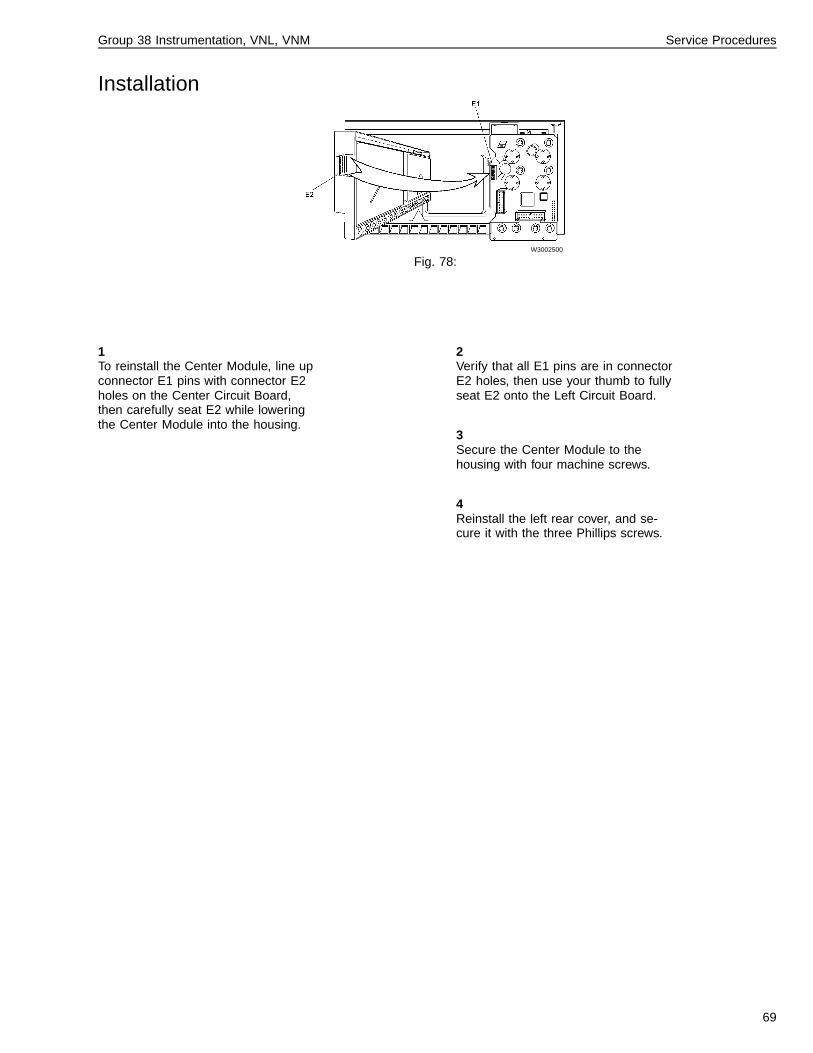
Group 38 Instrumentation, VNL, VNM Service Procedures
Installation
W3002500
Fig. 78:
1To reinstall the Center Module, line upconnector E1 pins with connector E2holes on the Center Circuit Board,then carefully seat E2 while loweringthe Center Module into the housing.
2Verify that all E1 pins are in connectorE2 holes, then use your thumb to fullyseat E2 onto the Left Circuit Board.
3Secure the Center Module to thehousing with four machine screws.
4Reinstall the left rear cover, and se-cure it with the three Phillips screws.
69

70

Group 38 Instrumentation, VNL, VNM Service Procedures
Tachometer, Speedometer andOdometer, Replacement
CAUTION
Before starting this procedure, see “General WorkPractices” page 3 for general safety precautions whenworking with the instrument cluster. Failure to followthe safety precautions may result in instrument clusterdamage.
Additional Information
• “Warranty Notice” page 60. Information about in-strument clusters still under warranty.
Removal
W3002517
Fig. 79:
1 Odometer Mounting Screws2 5–pin Connector
1Note: Attempts to remove and re-place individual gauges on the leftand center modules during the war-ranty period will void the clusterwarranty. Instead, the whole unitshould be exchanged. ONLY when atrained technician is reconfiguring areplacement instrument cluster maythe cluster be opened during the war-ranty period.
CAUTION
To prevent electrostatic discharge (ESD), which candamage the sensitive electronic components in the in-strument cluster, use a wrist grounding strap and ananti-static mat when working on the instrument cluster.Failure to do so can result in permanent damage tothe printed circuit boards in the instrument cluster. Donot place the cluster on a metal table or any metalsurface while servicing.
Remove Center Module (see “CenterModule, Replacement” page 66).
71

Group 38 Instrumentation, VNL, VNM Service Procedures
2
W3002502
Fig. 80:
CAUTION
To avoid damaging the gauges, do not pull on theneedle when removing the gauge assembly. Pulling onthe needle can make the gauges inaccurate.
The gauge assembly is held tightly bypin sockets. To remove, grasp the bot-tom of the tach/speedo assembly withyour thumb; place your 2nd and 3rdfingers underneath the face plate atthe top edge of the gauge assembly.Carefully rock the assembly from topto bottom while applying upward pres-sure until the gauge pins are free ofthe board sockets.
3To remove the Odometer Display as-sembly, remove the two Phillipsscrews which secure it to the rear ofthe speedometer.
Installation1Reinstall the Odometer Display withthe two Phillips screws, attaching it tothe rear of the speedometer.
2
CAUTION
To avoid damaging the gauges, do not push on theneedle when installing the gauge assembly. Pushingon the needle can make the gauges inaccurate.
Reinstall the tach/speedo assembly bystarting the 5–pin connector into theholes in the Center Module.
3
W3002503
Fig. 81:
When all five pins are inserted into theCenter Circuit Board, seat thetach/speedo gauge pins while guidingthe tabs on the sides of the gaugesinto the notches on the housing. Thetach/speedo assembly is correctly in-stalled when it is flush with the rear ofthe Center Board.
4Reinstall the Center Module (see“Center Module, Replacement” page66).
72

Group 38 Instrumentation, VNL, VNM Service Procedures
3811-03-02-04Left Gauge Module, Replace-ment
CAUTION
Before starting this procedure, see “General WorkPractices” page 3 for general safety precautions whenworking with the instrument cluster. Failure to followthe safety precautions may result in instrument clusterdamage.
Note: Individual gauges in the left and center modules ofthe VN instrument cluster are not serviceable during thewarranty period. Attempts to remove and replace indi-vidual gauges during the warranty period will voidthe cluster warranty. Instead, the whole unit may beexchanged.ONLY when a trained technician is changing the configu-ration of a replacement instrument cluster may thecluster be opened during the warranty period.
Removal1
CAUTION
To prevent electrostatic discharge (ESD), which candamage the sensitive electronic components in the in-strument cluster, use a wrist grounding strap and ananti-static mat when working on the instrument cluster.Failure to do so can result in permanent damage tothe printed circuit boards in the instrument cluster.
Remove cluster from vehicle (see“Instrument Cluster, Replacement”page 62). Place cluster on anti-staticmat. The anti-static mat must begrounded to the nearest electrical out-let. When working at the anti-staticworkbench, always keep a wrist strapconnected to the anti-static mat. Donot place the cluster on a metal tableor any metal surface while servicing.
2
W3000734
Fig. 82:
1) Connector E2 (part of the center circuitboard)2) Top cover screw location3) Bottom cover screw location4) Connector E4 to Graphic Display board un-derneath
Remove the Phillips screw at the topof the left rear cover, and the two atthe bottom, then lift off the cover.
Note: Connector E2 is part of theCenter Circuit Board.
73

Group 38 Instrumentation, VNL, VNM Service Procedures
3
CAUTION
Do not bend the printed circuit board. Bending theboard can result in damage to the board or compo-nents.
The Center Circuit Board connectorE2 is holding the Left Circuit Board as-sembly in at this point, so you willhave to remove the Center Module be-fore continuing (see “Center Module,Replacement” page 66).
4Carefully lift out the Left Circuit Boardassembly by lifting straight up. It is at-tached to the Graphic Display boardbelow at connector E4.
5
W3000991
Fig. 83:
CAUTION
To avoid damaging the gauge, do not push on theneedle when removing the gauge. Pushing on theneedle can make the gauge inaccurate.
Gauges and gauge blanks are heldtightly by their pin sockets. To remove,grasp the side of the gauge face platewith your thumb; place your 2nd and3rd fingers underneath the face plate(see illustration). Carefully rock thegauge from side to side while applyingupward pressure until the gauge pinsare free of the board sockets.
Installation1
CAUTION
To avoid damaging the gauge, do not push on theneedle when installing the gauge. Pushing on the nee-dle can make the gauge inaccurate.
Install the replacement gauge bygrasping the opposite corners of thegauge face plate and pushing thegauge pins into the socket onto thecircuit board. Do not push on theneedle. (For gauge blanks, see the fol-lowing steps.) It is correctly installedwhen its face plate is flush with theother gauges’ face plates.
Adding Gauge Blanks
2
W3002505
Fig. 84:
1) Gauge Blank2) Blank Support Assembly3) Pins4) Terminals
Install the new blank (1) into the clus-ter housing. Install the blank support(2) in the PC board into the terminals(4) where the gauge was removed. Al-ways install the support assembly inthe left and right pin holes, NOT thetop and bottom holes.
74

Group 38 Instrumentation, VNL, VNM Service Procedures
3
W3002501
Fig. 85:
Important! Before installing the LeftCircuit Board assembly, check connec-tor E4 pins and make sure they are allperfectly straight and parallel to eachother.
4Place the Left Circuit Board assemblyinto the housing while lining up E4 pinsinto the Graphic Display connector.
5Install the Center Module, paying par-ticular attention to connector E1 on theLeft Circuit Board assembly.
6Install the left rear cover and secure itwith three machine screws.
7Install the cluster into the dash (see“Instrument Cluster, Replacement”page 62).
8If installing a gauge blank into the En-gine Oil Pressure or Turbo BoostPressure gauges, use the Pro-Link9000 with the VOLVO card to enablethe gauge which is being added, or todisable the gauge which is being re-moved.
9Note: If the Left Circuit Board hasbeen replaced, update the odometerand hourmeter values to reflect the ve-hicle’s actual mileage and enginehours. This is done with the Pro-Link.
75

76

Feedback
One of our objectives is that workshop personnel should have access to correct andappropriate service manuals where it concerns fault tracing, repairs and maintenanceof Volvo trucks.In order to maintain the high standards of our literature, your opinions and experiencewhen using this manual would be greatly appreciated.If you have any comments or suggestions, make a copy of this page, write down yourcomments and send them to us, either via telefax or mailing directly to the addresslisted below.
To
Volvo Trucks North America, Inc.
Dept. 516 Service Publications
7825 National Service Road
P.O. Box 26115
Greensboro, NC 27402-6115
USA
Fax (336) 393-3170
From
..........................................................................
..........................................................................
..........................................................................
..........................................................................
..........................................................................
..........................................................................
..........................................................................
Comments/proposals
................................................................................................................................................................................
................................................................................................................................................................................
................................................................................................................................................................................
................................................................................................................................................................................
................................................................................................................................................................................
................................................................................................................................................................................
................................................................................................................................................................................
................................................................................................................................................................................
................................................................................................................................................................................
................................................................................................................................................................................
................................................................................................................................................................................
................................................................................................................................................................................
................................................................................................................................................................................
Concerns Service Manual: ...............................................................................................................................


Operation Numbers
3811-03-02-01 Instrument Cluster, Replacement . . . . . . . . . . . . . . . . . . . . . . . . 623811-03-02-02 Right Module, Replacement . . . . . . . . . . . . . . . . . . . . . . . . . . . 633811-03-02-03 Center Module, Replacement . . . . . . . . . . . . . . . . . . . . . . . . . . 663811-03-02-04 Left Gauge Module, Replacement . . . . . . . . . . . . . . . . . . . . . . . . 73

Volvo Trucks North America, Inc.P.O. Box 26115, Greensboro, NC 27402-6115
Volvo Trucks Canada, Ltd.6490 Vipond Drive, Mississauga, Ontario L5T 1W8
http://www.volvotrucks.volvo.com
PV776-TSP106805/1 2.1998 © Volvo Trucks North America, Inc., 1998