service manual - canon...
TRANSCRIPT

SERVICE MANUAL
COPYRIGHT © 2016 CANON INC. CANON Buffer Pass Unit-N1 Rev. 1 PRINTED IN U.S.A.
September 2, 2016 Rev. 1
Buffer Pass Unit-N1

IntroductionImportant Notices
ApplicationThis manual has been issued by Canon Inc. for qualified persons to learn technical theory, installation, maintenance, and repairof products.This manual covers all localities where the products are sold. For this reason, there may be information in this manual that doesnot apply to your locality.
CorrectionsThis manual may contain technical inaccuracies or typographical errors due to improvements or changes in products.When changes occur in applicable products or in the contents of this manual, Canon will release technical information as theneed arises. In the event of major changes in the contents of this manual over a long or short period, Canon will issue a newedition of this manual.
The following paragraph does not apply to any countries where such provisions are inconsistent with local law.
TrademarksThe product names and company names used in this manual are the registered trademarks of the individual companies.
CopyrightThis manual is copyrighted with all rights reserved. Under the copyright laws, this manual may not be copied, reproduced ortranslated into another language, in whole or in part, without the consent of Canon Inc.Copyright CANON INC. 2016
CautionUse of this manual should be strictly supervised to avoid disclosure of confidential information.
Explanation of SymbolsThe following symbols are used throughout this Service Manual.
Symbols Explanation Symbols ExplanationCheck.
1x
Remove the claw.
Check visually.
1x
Insert the claw.
Check a sound. Push the part.
Introduction

Symbols Explanation Symbols Explanation
1x
Disconnect the connector. Connect the power cable.
1x
Connect the connector. Disconnect the power cable.
1x
Remove the cable/wire from thecable guide or wire saddle.
Turn on the power.
1x
Install the cable/wire to the cableguide or wire saddle.
Turn off the power.
1x
Remove the screw.
1x
Loosen the screw.
1x
Install the screw.
1x
Tighten the screw.
Cleaning is needed. Measurement is needed.
The following rules apply throughout this Service Manual:1. Each chapter contains sections explaining the purpose of specific functions and the relationship between electrical and
mechanical systems with reference to the timing of operation.In the diagrams, represents the path of mechanical drive; where a signal name accompanies the symbol, the arrow
indicates the direction of the electric signal.The expression "turn on the power" means flipping on the power switch, closing the front door, and closing the delivery unitdoor, which results in supplying the machine with power.
2. In the digital circuits, '1' is used to indicate that the voltage level of a given signal is "High", while '0' is used to indicate "Low".(The voltage value, however, differs from circuit to circuit.) In addition, the asterisk (*) as in "DRMD*" indicates that the DRMDsignal goes on when '0'.In practically all cases, the internal mechanisms of a microprocessor cannot be checked in the field. Therefore, the operationsof the microprocessors used in the machines are not discussed: they are explained in terms of from sensors to the input ofthe DC controller PCB and from the output of the DC controller PCB to the loads.
The descriptions in this Service Manual are subject to change without notice for product improvement or other purposes, andmajor changes will be communicated in the form of Service Information bulletins.All service persons are expected to have a good understanding of the contents of this Service Manual and all relevant ServiceInformation bulletins and be able to identify and isolate faults in the machine.
Introduction

ContentsSafety Precautions...............................................................................................1
Notes Before Servicing........................................................................................................................2Points to Note at Cleaning...................................................................................................................2Notes On Assembly/Disassembly....................................................................................................... 2
Notes on Assembly/Disassembly........................................................................................................... 2
1. Product Overview.............................................................................................3Specifications...................................................................................................................................... 4
Specifications....................................................................................................................................... 4Name of Parts..................................................................................................................................... 5
External View........................................................................................................................................5Cross Section....................................................................................................................................... 5
2. Technical Explanation..................................................................................... 6Basic Configuration............................................................................................................................. 7
Basic Constitution................................................................................................................................. 7Overview of Electrical Circuitry...............................................................................................................7
Controls...............................................................................................................................................8Controls............................................................................................................................................... 8
Basic Operation...................................................................................................................................9Basic Operation.................................................................................................................................... 9Drive Configuration............................................................................................................................... 9
Jam Detection................................................................................................................................... 10Overview............................................................................................................................................ 10Jam Types..........................................................................................................................................10
Power Supply.................................................................................................................................... 11Power Supply Route............................................................................................................................11Protection Function............................................................................................................................. 11
Upgrading..........................................................................................................................................12Upgrading...........................................................................................................................................12
3. Periodical Service.......................................................................................... 13Periodical Service Operation Item.....................................................................................................14
Periodically Replaced Parts................................................................................................................. 14Consumable Parts...............................................................................................................................14
4. Disassembly/Assembly................................................................................. 15Removing this Machine from the Host Machine................................................................................16
Removing this Machine....................................................................................................................... 16List of Parts....................................................................................................................................... 21
Sensors, Motor, PCB...........................................................................................................................21External Cover...................................................................................................................................22
Removing the Buffer Pass Upper Unit.................................................................................................. 22
Contents
i

Motor................................................................................................................................................. 23Removing the Buffer Pass Motor (M401).............................................................................................. 23
Sensor...............................................................................................................................................24Removing the Buffer Pass Inlet Sensor (M401)..................................................................................... 24Removing the Buffer Pass Outlet Sensor (M402)...................................................................................25Removing the OPEN Detection Sensor (M403)..................................................................................... 26
PCB...................................................................................................................................................27Removing the Buffer Pass Controller PCB (PCB401).............................................................................27
5. Adjustment..................................................................................................... 28Basic Adjustment...............................................................................................................................29
Basic Adjustments...............................................................................................................................29
6. Installation...................................................................................................... 30Checking Before Installation..............................................................................................................31
Points to Note on Installation................................................................................................................31Product Name.....................................................................................................................................31Check Items When Turning OFF the Main Power.................................................................................. 31
Unpacking......................................................................................................................................... 32Unpacking Procedure.......................................................................................................................... 32
Checking the Contents......................................................................................................................33Installation Procedure........................................................................................................................34
Installation Procedure..........................................................................................................................34Making Checks after Completion of Installation Work.......................................................................41
Disposal Parts Check.......................................................................................................................... 41Operation Check................................................................................................................................. 41
APPENDICES......................................................................................................42Service Tools.....................................................................................................................................43
Solvents and Oils................................................................................................................................ 43Special Tools...................................................................................................................................... 43
General Circuit Diagram....................................................................................................................44General Circuit Diagram...................................................................................................................... 44
Contents
ii

Safety PrecautionsNotes Before Servicing......................... 2Points to Note at Cleaning.................... 2Notes On Assembly/Disassembly.........2

Notes Before Servicing
CAUTION:At servicing, be sure to turn off the power source according to the specified steps and disconnect the power plug.
CAUTION:Do not turn off the power switch when downloading is under way. Turning off the main power switch while downloading isunder way can disable the machine.
Points to Note at Cleaning
CAUTION:When performing cleaning using organic solvent such as alcohol, be sure to check that the component of solvent isvaporized completely before assembling.
Notes On Assembly/Disassembly
Notes on Assembly/DisassemblyFollow the items below to assemble/disassemble the device.
1. Disconnect the power plug to avoid any potential dangers during assembling/disassembling works.2. If not specially instructed, reverse the order of disassembly to reinstall.3. Ensure to use the right screw type (length, diameter, etc.) at the right position when assembling.4. To keep electric conduction, binding screws with washers are used to attach the grounding wire and the varistor. Ensure to
use the right screw type when assembling.5. Unless it is specially needed, do not operate the device with some parts removed.6. Never remove the paint-locked screws when disassembling.7. During disassembly, reassembly or transportation of the printer, remove the cartridge if required. When the cartridge is out
of the printer, put it in a protective bag even in a short period of time to prevent the adverse effect of light.8. When you replace the part that the rating plate or the product code label is attached, be sure to remove the rating plate or
the product code label and put it to the new part.
Safety Precautions
2

Product Overview1 Specifications........................................4Name of Parts....................................... 5

Specifications
Specifications
Item Description RemarksPlacement Center Installation Build-in type Paper Type (Bufferpass delivery tray)
Thin paper, Plain paper, Heavy paper, Recycled paper, Transparency, Labels, Postcard Transfer from thehost machine
Stacking size (Bufferpass delivery tray)
Feed direction: 148.0 to 431.8mmWidth direction: 98.0 to 297.0mm
Long original pa-per (630mm,1200mm) is availa-ble to fed if jam isnot occurred.
Stacking capacity(Buffer pass deliverytray)
Height 15mm or less (equivalent of 100 sheets) • Transparency,Tracing Paper andLabels are 20sheets or less.• Envelope are 4sheets or less.
Dimensions W: 489mm × D: 493mm × H: 184mm Weight Approx 4.5Kg Power Supply Supplied by the Finisher Option Unavailable
1. Product Overview
4

Name of Parts
External View
[1]
[2]
No. Name[1] Buffer pass feed outlet port[2] Buffer pass delivery tray
Cross Section
[1] [1] [1] [1][2][3]
[4]
No Name[1] Feed Roller[2] Buffer Pass Inlet Sensor[3] Buffer Pass Exit Sensor[4] OPEN Detection Sensor
1. Product Overview
5

TechnicalExplanation2Basic Configuration...............................7Controls.................................................8Basic Operation.....................................9Jam Detection..................................... 10Power Supply......................................11Upgrading............................................12
Basic Configuration
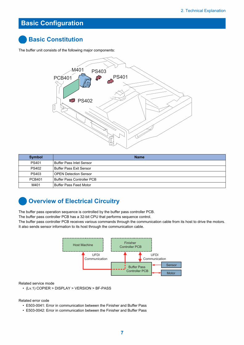
Basic ConstitutionThe buffer unit consists of the following major components:
PS402
PS403PS401
M401
PCB401
Symbol NamePS401 Buffer Pass Inlet SensorPS402 Buffer Pass Exit SensorPS403 OPEN Detection Sensor
PCB401 Buffer Pass Controller PCBM401 Buffer Pass Feed Motor
Overview of Electrical CircuitryThe buffer pass operation sequence is controlled by the buffer pass controller PCB.The buffer pass controller PCB has a 32-bit CPU that performs sequence control.The buffer pass controller PCB receives various commands through the communication cable from its host to drive the motors.It also sends sensor information to its host through the communication cable.
Finisher
Controller PCBHost Machine
Motor
Sensor
UFDI
Communication
UFDI
Communication
Buffer Pass
Controller PCB
Related service mode• (Lv.1) COPIER > DISPLAY > VERSION > BF-PASS
Related error code• E503-0041: Error in communication between the Finisher and Buffer Pass• E503-0042: Error in communication between the Finisher and Buffer Pass
2. Technical Explanation
7

Controls
Controls
Item ReferenceBasic Operation “Basic Operation” on page 9Jam Detection “Jam Detection” on page 10Upgrading “Upgrading” on page 12
2. Technical Explanation
8

Basic Operation
Basic OperationThe device feeds paper that is fed from the Staple Finisher / the Booklet Finisher.
Drive ConfigurationThe following is a diagram showing the drive system of the buffer path.
M401
PS401PS402
Symbol NameM401 Buffer Pass Feed MotorPS401 Buffer Pass Inlet SensorPS402 Buffer Pass Exit Sensor
2. Technical Explanation
9
Jam Detection
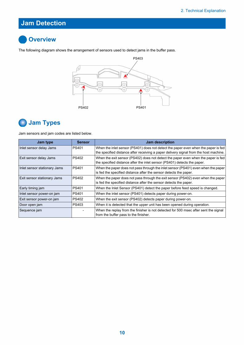
OverviewThe following diagram shows the arrangement of sensors used to detect jams in the buffer pass.
PS402 PS401
PS403
Jam TypesJam sensors and jam codes are listed below.
Jam type Sensor Jam descriptionInlet sensor delay Jams PS401 When the inlet sensor (PS401) does not detect the paper even when the paper is fed
the specified distance after receiving a paper delivery signal from the host machine.Exit sensor delay Jams PS402 When the exit sensor (PS402) does not detect the paper even when the paper is fed
the specified distance after the inlet sensor (PS401) detects the paper.Inlet sensor stationary Jams PS401 When the paper does not pass through the inlet sensor (PS401) even when the paper
is fed the specified distance after the sensor detects the paper.Exit sensor stationary Jams PS402 When the paper does not pass through the exit sensor (PS402) even when the paper
is fed the specified distance after the sensor detects the paper.Early timing jam PS401 When the Inlet Sensor (PS401) detect the paper before feed speed is changed.Inlet sensor power-on jam PS401 When the inlet sensor (PS401) detects paper during power-on.Exit sensor power-on jam PS402 When the exit sensor (PS402) detects paper during power-on.Door open jam PS403 When it is detected that the upper unit has been opened during operation.Sequence jam - When the replay from the finisher is not detected for 500 msec after sent the signal
from the buffer pass to the finisher.
2. Technical Explanation
10

Power Supply
Power Supply RouteWhen a host machine is turned on, 24V and 5V are supplied in buffer pass controller PCB by a finisher.The 5V is converted into 3.3V by the regulator IC on the buffer pass controller PCB.The 5V is used to drive the sensors and logic.
(IC4)
Buffer Pass Controller PCB
24V
3.3V
24VFinisher Controller PCB
Motor Driver IC
5V
Motors
fuse
(FU1)
fuse
(FU2) (IC5)
Regulator IC
Host Machine
12V
24V
Sensor
Protection FunctionThe power input circuit of buffer pass controller PCB is also provided with a fuse which is blown when an excessive current flows.The 24V circuits (used to drive the motors) are provided with the fuses or the motor drivers with an overcurrent protective functionto provide protection from the over current.
2. Technical Explanation
11

Upgrading
UpgradingWhen upgrading the firmware of the buffer pass controller PCB, upgrade from the host machine.(Refer to the service manual for the host machine as to the detail.)
2. Technical Explanation
12

Periodical Service3 Periodical Service Operation Item.......14

Periodical Service Operation Item
Periodically Replaced PartsThere are no parts that need to be periodically replaced on the buffer pass unit.
Consumable PartsThere is no consumable parts on the buffer pass unit.
3. Periodical Service
14

Disassembly/Assembly4Removing this Machine from the Host
Machine...........................................16List of Parts......................................... 21External Cover.................................... 22Motor...................................................23Sensor.................................................24PCB.....................................................27

Removing this Machine from the Host Machine
Removing this Machine1. Open the Front Cover [1].
[1]
2. Remove the 1 Screw [1].
1x[1]
3. Detach the Finisher from the host machine.
4. Disassembly/Assembly
16

4. Disconnect the Interface Cable [1].
1x[1]
5. Remove the metal fixture [1].• 4 screws [2]
[2]
4x
[1]
[2]
6. Remove the Rear Relay Cover [1].• 1 Screw [2]
1x [1]
[2]
4. Disassembly/Assembly
17

7. Open the Front Cover.
8. Open the Front Upper Cover.
9. Remove the Left Upper Cover Unit [1].• 1 Screw [2]
1x
[1]
[2]
10. Remove the Left Cover [1].• 3 Screws [2]
4. Disassembly/Assembly
18

[1]
3x
[2]
11. Disconnect the 2 connectors [1].• 1 Reuse Band [2]
2x 1x
[1]
[2]
12. Remove the Reversal Guide [1].
[1]
4. Disassembly/Assembly
19

13. Remove the 2 screws [1].
2x
[1]
14. Remove the Buffer Pass Unit.• 2 Hooks [1]
2x
[1]
4. Disassembly/Assembly
20
List of Parts
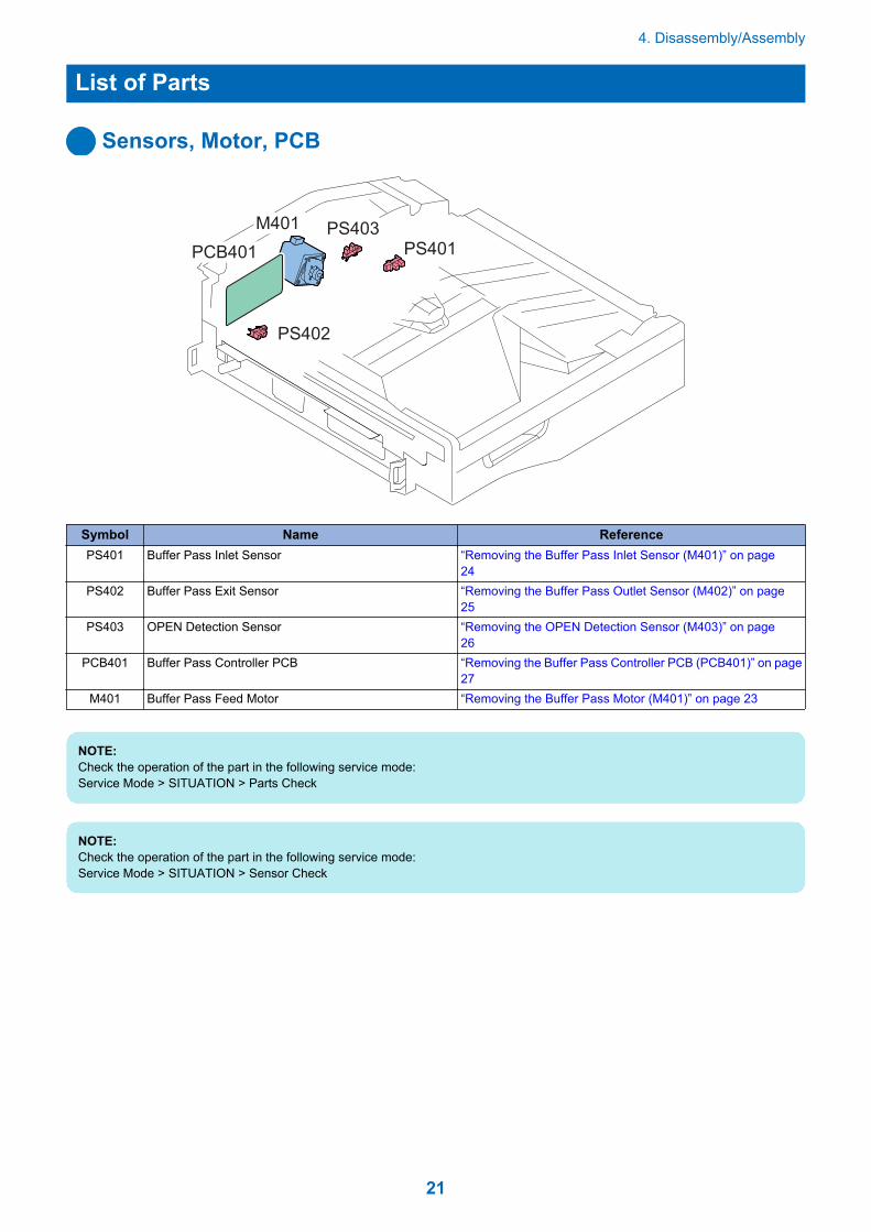
Sensors, Motor, PCB
PS402
PS403PS401
M401
PCB401
Symbol Name ReferencePS401 Buffer Pass Inlet Sensor “Removing the Buffer Pass Inlet Sensor (M401)” on page
24PS402 Buffer Pass Exit Sensor “Removing the Buffer Pass Outlet Sensor (M402)” on page
25PS403 OPEN Detection Sensor “Removing the OPEN Detection Sensor (M403)” on page
26PCB401 Buffer Pass Controller PCB “Removing the Buffer Pass Controller PCB (PCB401)” on page
27M401 Buffer Pass Feed Motor “Removing the Buffer Pass Motor (M401)” on page 23
NOTE:Check the operation of the part in the following service mode:Service Mode > SITUATION > Parts Check
NOTE:Check the operation of the part in the following service mode:Service Mode > SITUATION > Sensor Check
4. Disassembly/Assembly
21
External Cover
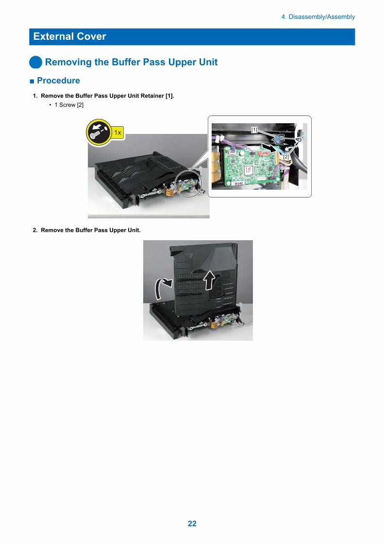
Removing the Buffer Pass Upper Unit
■ Procedure1. Remove the Buffer Pass Upper Unit Retainer [1].
• 1 Screw [2]
[1]
[2]
1x
2. Remove the Buffer Pass Upper Unit.
4. Disassembly/Assembly
22

Motor
Removing the Buffer Pass Motor (M401)
■ Procedure1. Remove the Buffer Pass Motor Unit [1].
• 3 Screws [2]• 1 Connector [3]
3x
1x
[1] [3]
[2]
2. Remove the Buffer Pass Motor [1].• 2 Screws [2]
[1]
[2]
2x
4. Disassembly/Assembly
23

Sensor
Removing the Buffer Pass Inlet Sensor (M401)
■ Procedure1. Turn over the Buffer Pass Unit.
2. Remove the Buffer Pass Inlet Sensor [1].• 1 Connector [2]
4. Disassembly/Assembly
24

1x
[1] [2]
Removing the Buffer Pass Outlet Sensor (M402)
■ Procedure 1. Turn over the Buffer Pass Unit.
2. Remove the Buffer Pass Outlet Sensor [2].• 1 Connector [1]
4. Disassembly/Assembly
25

1x [1] [2]
Removing the OPEN Detection Sensor (M403)
■ Procedure1. Remove the Buffer Pass Upper Unit.“Removing the Buffer Pass Upper Unit” on page 22
2. Remove the OPEN Detection Sensor [2].• 1 Connector [1]
1x
[2] [1]
4. Disassembly/Assembly
26

PCB
Removing the Buffer Pass Controller PCB (PCB401)
■ Procedure1. Remove the Buffer Pass Controller PCB [1].
• 1 Screw [2]• 5 Connectors [3]• 1 Locking Support [4]
1x[1]
[2]
[3]
[3]
[4]5x
[3]
4. Disassembly/Assembly
27

Adjustment5 Basic Adjustment................................ 29

Basic Adjustment
Basic AdjustmentsBuffer pass unit does not have adjustment work.
5. Adjustment
29

Installation6 Checking Before Installation............... 31Unpacking........................................... 32Checking the Contents........................33Installation Procedure......................... 34Making Checks after Completion of
Installation Work..............................41
Checking Before Installation
Points to Note on InstallationInstall this Equipment after installing the Host Machine.
Product NameSafety regulations require the product's name to be registered. In some regions where this product is sold, the following namesmay be registered instead.
• F280762
Check Items When Turning OFF the Main PowerCheck that the main power switch is OFF.
1. Turn OFF the main power switch of the Host Machine.2. Be sure that control panel display and main power lamp are both turned OFF, and then disconnect the power plug.
6. Installation
31

Unpacking
Unpacking Procedure
1. Open the container box, and then take out the included parts and cushioning materials.
2. Open the plastic sheet. Take out the Buffer Pass Unit by holding its both sides as shown in the figure, and thenremove all the tapes and the cushioning materials.
FRONT
6. Installation
32
Checking the Contents
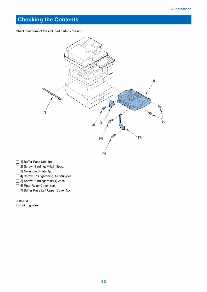
Check that none of the included parts is missing.
[6]
[1]
[2]
[2]
[7]
[5]
[3][4]
[1] Buffer Pass Unit 1pc.[2] Screw (Binding; M4x8) 3pcs.[3] Grounding Plate 1pc.[4] Screw (RS tightening; M3x8) 2pcs.[5] Screw (Binding; M4x14) 2pcs.[6] Rear Relay Cover 1pc.[7] Buffer Pass Left Upper Cover 1pc.
<Others>Including guides
6. Installation
33

Installation Procedure
Installation Procedure
CAUTION:Make sure that the Host Machine is turned off andthe power plug is disconnected from the outlet.
1. When the Reversal Guide has been installed to thehost machine, remove it.
• 2 Claws
2. Remove the Delivery Rear Cover (Upper/Lower).• 1 Screw• 1 Hook
1x
3. Remove the Sensor Flag of the Delivery Tray FullDetection Sensor 1 (the lower sensor flag in thefigure).
4. Install the Delivery Rear Cover (Upper/Lower).• 2 Bosses• 1 Hook• 1 Screw
1x
6. Installation
34

5. Remove the Inner Cover (Upper/Lower).• 2 Screws
CAUTION:Be careful not to forget to remove the Inner Cover(Upper/Lower), if it is forgotten to remove the cover, theBuffer Pass is not grounded, so that the controller ofthe Host Machine may be damaged by an electro staticnoise.
2x
RS Tightening
(M3x8)
6. Remove the Inner Face Seal.
7. Remove the Face Cover.• 1 Claw
8. Remove the Face Cover.• 1 Claw
6. Installation
35

9. Open the Front Cover.
10. Open the Front Upper Cover.
11. Remove the Left Upper Cover Unit.• 1 Screw
1x
12. Remove the Left Cover.• 3 Screws
3x
13. Remove the Subtray.• 1 Hook• 2 Claws
6. Installation
36

14. Set the Inner Buffer Pass Unit to the host machineas shown in the figure carefully so that the hostmachine can not be damaged.
• 2 Projections• 2 Hooks
NOTE:Confirm that the 2 projections at rear and 2 hooks at frontof the Buffer Pass Unit are inserted securely.
15. Connect the connector of the Buffer Pass Unit to theHost Machine.
• 2 Connectors• 1 Reuse Band
2x 1x
16. Fix the Buffer Pass Unit to the Host Machine.• 2 Screws (Binding ; 4x8)
2x
Binding
(M4x8)
17. Install the Reversal Guide.• 2 Claws
NOTE:Surely insert the Reversal Guide till a gap disappears.
6. Installation
37

18. Remove the Left Upper Cover, which excluded inprocedure 11.
• 1 Screw• 3 Hooks
1x
19. Install the Buffer Pass Left Upper Cover to the LeftUpper Cover Unit.
NOTE:Protection Sheet of Buffer Pass Left Upper Cove isremoved at later procedure.
• 3 Hooks• 1 Screw (P Tightening ; M4x10)
1x
20. Install the Left Cover.• 3 Screw (RS Tightening ; M3x8)
3x
21. Install the Left Upper Cover Unit.• 4 Claws• 1 Screw (RS Tightening ; M3x8)
1x
6. Installation
38

22. Remove the Protection Sheet from the Buffer PassLeft Upper Cover.
23. Close the Front Upper Cover.
24. Close the Front Cover.
25. Install the Rear Relay Cover.• 3 Hooks• 1 Screw (Binding ; M4x8)
1x
Binding
(M4x8)
26. Remove the 2 Face Seals (White) from Left Cover.
6. Installation
39

27. Install the Grounding Plate.• 2 Screws (Binding ; M4x14)• 2 Screws (RS Tightening ; M3x8)
4x
RS Tightening
(M3x8)
Binding
(M4x14)
6. Installation
40
Making Checks afterCompletion of InstallationWork
Disposal Parts Check1. Following disposal parts are remained after
completion of the installation work.[1] Sensor Flag of the Delivery Tray Full Detection
Sensor1 1pc.[2] Face Cover 1pc.[3] Face Cover 1pc.[4] Subtray 1pc.[5] Inner Cover (Upper) 1pc.[6] Inner Cover (Lower) 1pc.[7] Inner Face Seal 1pc[8] Screw (RS Tightening ; M3x8) 2pcs.[9] Left Upper Cover 1pc.[10] Protection Sheet 1pc.[11] Face Seal (White) 2pcs.
Operation Check
1. Turn ON the main power of the Host Machine afterinstalling the Finisher.
2. Check the operation such as paper feed to makesure that problems such as a jam or malfunction donot occur.
6. Installation
41

APPENDICESService Tools...................................... 43General Circuit Diagram......................44

Service Tools
Solvents and Oils
No. Name Uses Composition Remarks1 Alcohol Cleaning;
e.g.,plastic, rubber parts, externalcovers.
Fluoride-family hydrocar-bonAlcoholSurface activating agentWater
• Do not bring near fire• Procure locally• Substitute: IPA (isopropyl
alcohol)
2 Solvent Cleaning;e.g.,metal, oil or toner stain
Fluoride-family hydrocar-bonChlorine-family hydrocar-bonAlcohol
• Do not bring near fire• Procure locally• Substitute: MEK
3 Lubricating oil(EM-50L) Lubrication;friction areas.
Special oilSpecial solid lubricatiingagentLithium soap
• Tool No.:HY9-0007
Special ToolsNone
Service Tools
43

General Circuit Diagram
General Circuit Diagram12345678910
12345678910
F
E
D
C
B
A
F
E
D
C
B
A
P.1
General Circuit Diagram
44