service manual bcgt gasol generators manual/44518_rev1_4.5-9.6bcg… · a warning exhaust gasses...
TRANSCRIPT
~ £ R II
" ~ . .., 'f. ~ "'. {, '" o q
IlI."D~'
SERVICE MANUAL ". . . .
BCGT GASOL GENERATORS
CARBURETOR MODELS ... '
4.5 KW BCGTC 60Hz 3.75 KW BCGTC 50Hz 7.2 KW BCGTC 60Hz 6.0 KW BCGTC 50Hz 9.6 KW BCGTC 60Hz 8.0 KW BCGTC 50Hz
ELECTRONIC FUEL INJECTION MODELS "'---'::::"-- .. .
. 4.5 KW BCGTE 60Hz , 3.75 KW BCGTE 50Hz 7.2 KW BCGTE 60Hz 6.0 KW BCGTE 50Hz
PUBLICATION NO.44518
1ST EDITION
NOVEMBER 1999
WESTERBEKE WESTERSEKE CORPORATION' MYLES STANDISH· INDUSTRIAL PARK ISO JOHN HANCOCK ROAD. TAUNTON. MA 0271JO.731S"U.s.A.
TEL: (508)8ZJ.7677· FAX: (508)88409688 • WEBSITE: www.weSTERBEKE.COM ... NAIl''''' MemMr NationDl MariM Manufacturers Association • •

Gasoline with an ETHANOL content higher than 10% (E10) is not allowed
and may void warranty.
Engines & Generators
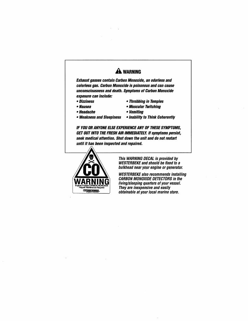
A WARNING
Exhaust gasses contain Carbon Monoxide, an odorless and colorless gas. Carbon Monoxide is poisonous and can cause unconsciousness and death. Symptoms of Carbon Monoxide exposure can include: -Dizziness -Nausea -Headache
- Throbbing in Temples - Muscular Twitching - Vomiting
- Weakness and Sleepiness -Inability to Think Coherently
IF YOU OR ANYONE ELSE EXPERIENCE ANY OF THESE SYMPTOMS, GET OUT INTO THE FRESH AIR IMMEDIATELY. If symptoms persist, seek medical attention. Shut down the unit and do not restart until it has been inspected and repaired.
This WARNING DECAL is provided by WESTERBEKE and should be fixed to a bulkhead near your engine or ge.nerator.
WESTERBEKE also recommends installing CARBON MONOXIDE DETECTORS in the living/sleeping quarters of your vessel. They are inexpensive and easily obtainable at your local marine store.
SAFETY INSTRUCTIONS INTRODUCTION Read this safety manual carefully. Most accidents are caused by failure to follow fundamental rules and precautions. Know when dangerous conditions exist and take the necessary precautions to protect yourself, your personne~ and your machinery. The following safety instructions are in compliance with the American Boat and Yacht Council (ABYC) standards.
PREVENT ELECTRIC SHOCK
A WARNING: Do not touch AC electrical connections while engine is running, or when connected to shore power. Lethal voltage is present at these connections!
• Do not operate this machinery without electrical enclosures and covers in place.
• Shut off electrical power before accessing electrical equipment.
• Use insulated mats whenever working on electrical equipment.
• Make sure your clothing and skin are dry, not damp (particularly shoes) when handling electrical equipment.
• Remove wristwatch and all jewelry when working on electrical equipment.
• Do not connect utility shore power to vessel's AC circuits, except through a ship-to-shore double throw transfer switch. Damage to vessel's AC generator may result if this procedure is not followed.
• Electrical shock results from handling a charged capacitor. Discharge capacitor by shorting terminals together.
PREVENT BURNS - HOT ENGINE
A WARNING: Do not touch hot engine parts or exhaust system components. A running engine gets very hot!
• Always check the engine coolant level at the coolant recovery tank.
A ,WARNING: Steam can cause injury or death!
• In case of an engine overheat, allow the engine to cool before touching the engine or checking the coolant.
PREVENT BURNS - FIRE
A WARNING: Fire can cause injury or death!
• Prevent flash fires. Do not smoke or permit flames or sparks to occur near the carburetor, fuel line, filter, fuel pump, or other potential sources of spilled fuel or fuel vapors. Use a suitable container to catch all fuel when removing the fuel line, carburetor, or fuel filters.
• Do not operate with a Coast Guard Approved flame arrester removed. Backfire can cause severe injury or death.
• Do not operate with the air cleaner/silencer removed. Backfire can cause severe injury or death.
• Do not smoke or permit flames or sparks to occur near the fuel system. Keep the compartment and the engine/generator clean and free of debris to minimize the chances of fire. Wipe up all spilled fuel and engine oil.
• Be aware - diesel fuel will burn.
PREVENT BURNS - EXPLOSION
A WARNING: Explosions from fuel vapors can cause injury or death!
• Follow re-fueling safety instructions. Keep the vessel's hatches closed when fueling. Open and ventilate cabin after fueling. Check below for fumes/vapor before running the blower. Run the blower for four minutes before starting your engine.
• All fuel vapors are highly explosive. Use extreme care when handling and storing fuels. Store fuel in a well-ventilated area away from spark-producing equipment and out of the reach of children.
• Do not fill the fuel tank(s) while the engine is running. • Shut off the fuel service valve at the engine when servicing
the fuel system. Take care in catching any fuel that might spill. DO NOT allow any smoking, open flames, or other sources of fire near the fuel system or engine when servicing. Ensure proper ventilation exists when servicing the fuel system.
• Do not alter or modify the fuel system. • Be sure all fuel supplies have a positi..,e shutoff valve.
• Be certain fuel line fittings are adequately tightened and free of leaks.
• Make sure a fire extinguisher is installed nearby and is properly maintained. Be familiar with its proper use. Extinguishers rated ABC by the,NFPA are appropriate for all applications encountered in this environment.
Engines & Generators
SAFETY INSTRUCTIONS ACCIDENTAL STARTING
A WARNING: Accidental starting can cause injury or death!
• Disconnect the battery cables before servicing the engine! generator. Remove the negative lead first and reconnect it last.
• Make certain all personnel are clear of the engine before starting.
• Make certain all covers, guards, and hatches are reinstalled before starting the engine.
BATIERY EXPLOSION
A WARNING: Battery explosion can cause injury or death!
• Do not smoke or allow an open flame near the battery being serviced. Lead acid batteries emit hydrogen, a highly explosive gas, which can be ignited by electrical arcing or by lit tobacco products. Shut off all electrical equipment in the vicinity to prevent electrical arcing during servicing.
• Never connect the negative (-) battery cable to the positive (+) connection terminal of the starter solenoid. Do not test the battery condition by shorting the terminals together. Sparks could ignite battery gases or fuel vapors. Ventilate any compartment containing batteries to prevent accumulation of explosive gases. To avoid sparks, do not disturb the battery charger connections while the battery is being charged.
• Avoid contacting the terminals with tools, etc., to prevent burns or sparks that could cause an explosion. Remove wristwatch, rings, and any other jewelry before handling the battery.
• Always tum the battery charger off before disconnecting the battery connections. Remove the negative lead first and reconnect it last when disconnecting the battery.
BATIERYACID
A WARNING: Sulfuric acid in batteries can cause severe injury or death!
• When servicing the battery or checking the electrolyte level, wear rubber gloves, a rubber apron, and eye protection. Batteries contain sulfuric acid which is destructive. If it comes in contact with your skin, wash it off at once with water. Acid may splash on the skin or into the eyes inadvertently when removing electrolyte caps.
TOXIC EXHAUST GASES
A WARNING: Carbon monoxide (CO) is a deadly gas!
• Ensure that the exhaust system is adequate to expel gases discharged from the engine. Check the exhaust system regularly for leaks and make sure the exhaust manifolds are securely attached and no warping exists. Pay close attention to the manifold, water injection elbow, and exhaust pipe nipple.
• Be sure the unit and its surroundings are well ventilated.
• In addition to routine inspection of the exhaust system, install a carbon monoxide detector. Consult your boat builder or dealer for installation of approved detectors.
• For additional information refer to ABYC T-22 (educational information on Carbon Monoxide).
A WARNING: Carbon monoxide (CO) is an invisible odorless gas. Inhalation produces flu-like symptoms, nausea or death!
• Do not use copper tubing in diesel exhaust systems. Diesel fumes can rapidly destroy copper tubing in exhaust systems. Exhaust sulfur causes rapid deterioration of copper tubing resulting in exhaust/water leakage.
• Do not install exhaust outlet where exhaust can be drawn through portholes, vents, or air conditioners. If the engine exhaust discharge outlet is near the waterline, water could enter the exhaust discharge outlet and close or restrict the flow of exhaust. Avoid overloading the craft.
• Although diesel engine exhaust gases are not as toxic as exhaust fumes from gasoline engines, carbon monoxide gas is present in diesel exhaust fumes. Some of the symptoms or signs of carbon monoxide inhalation or poisoning are: Vomiting Dizziness
Throbbing in temples Muscular twitching
Intense headache Weakness and sleepiness
AVOID MOVING PARTS
A WARNING: Rotating parts can cause injury or death!
• Do not service the engine while it is running. If a situation arises in which it is absolutely necessary to make operating adjustments, use extreme care to avoid touching moving parts and hot exhaust system components.
Engines & Generators
ii
SAFETY INSTRUCTIONS • Do not wear loose clothing or jewelry when servicing
equipment; tie back long hair and avoid wearing loose jackets, shirts, sleeves, rings, necklaces or bracelets that could be caught in moving parts.
• Make sure all attaching hardware is properly tightened. Keep protective shields and guards in their respective places at all times.
• Do not check fluid levels or the drive belt's tension while the engine is operating.
• Stay clear of the drive shaft and the transmission coupling when the engine is running; hair and clothing can easily be caught in these rotating parts.
HAZARDOUS NOISE
A WARNING: High noise levels can cause hearing loss!
• Never operate an engine without its muffler installed.
• Do not run an engine with the air intake (silencer) removed.
• Do not run engines for long periods with their enclosures open.
A WARNING: Do not work on machinery when you are mentally or physically incapacitated by fatigue!
OPERATORS MANUAL Many of the preceding safety tips and warnings are repeated in your Operators Manual along with other cautions and notes to highlight critical information. Read your manual carefully, maintain your equipment, and follow all safety procedures.
ENGINE INSTALLATIONS Preparations to install an engine should begin with a thorough examination of the American Boat and Yacht Council's (ABYC) standards. These standards are a combination of sources including the USCG and the NFPA.
Sections of the ABYC standards of particular interest are:
H-2 Ventilation P-l Exhaust systems P-4 Inboard engines E-9 DC Electrical systems
All installations must comply with the Federal Code of Regulations (FCR).
ABYC, NFPA AND USCG PUBLICATIONS FOR INSTALLING DIESEL ENGINES Read the following ABYC, NFPA and USCG publications for safety codes and standards. Follow their recommendations when installing your engine.
ABYC (American Boat and Yacht Council) "Safety Standards for Small Craft"
Order from:
ABYC 15 East 26th Street New York, NY 10010
NFPA (National Fire Protection Association) "Fire Protection Standard for Motor Craft"
Order from:
National Fire Protection Association 11 Tracy Drive Avon Industrial Park Avon, MA02322
USCG (United States Coast Guard) "USCG 33CFR183"
Order from:
U.S. Government Printing Office Washington, D.C. 20404
Engines & Generators
iii
INSTALLATION
When installing WESTERBEKE engines and generators it is important that strict attention be paid to the following information:
CODES AND REGULATIONS Strict federal regulations, ABYC guidelines, and safety codes must be complied with when installing engines and generators in a marine environment.
SIPHON-BREAK For installations where the exhaust manifold/water injected exhaust elbow is close to or will be below the vessel's waterline, provisions must be made to install a siphonbreak in the raw water supply hose to the exhaust elbow. 'This hose must be looped a minimum of 20" above the vessel's waterline. Failure to use a siphon-break when the exhaust manifold injection port is at or below the load waterline will result in raw water damage to the engine and possible flooding of the boat. If you have any doubt about the position of the water-injected exhaust elbow relative to the vessel's waterline under the vessel's various operating conditions, instaU a siphon-break. NOTE: A siphon-break requires periodic inspection and cleaning to ensure proper operation. Failure to properly maintain a siphon-break can result in catastrophic engine damage. Consult the siphon-break manufacturer for proper maintenance.
EXHAUST SYSTEM The exhaust hose must be certified for marine use. The system must be designed to prevent water from entering the exhaust under any sea conditions and at any angle of the vessels hull.
A detailed 40 page Marine Installation Manual covering gaSOline and diesel, engines and generators, is available from your WESTERBEKE dealer.
Engines & Generators
iv
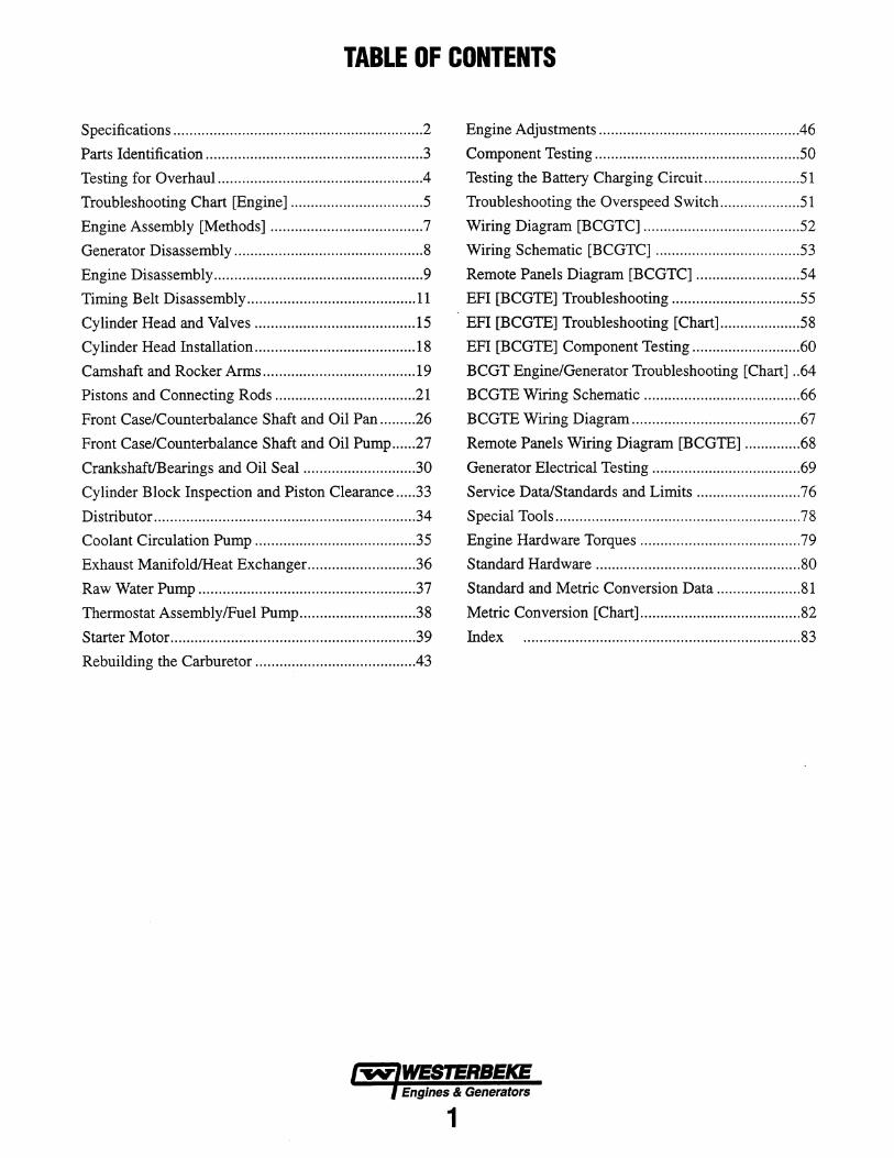
TABLE OF CONTENTS
Specifications .............................................................. 2 Engine Adjustments ................................................. .46
Parts Identification ..................................................... .3 Component Testing ................................................... 50
Testing for Overhaul .................................................. .4 Testing the Battery Charging Circuit.. ...................... 51
Troubleshooting Chart [Engine] ................................. 5 Troubleshooting the Overspeed Switch .................... 51
Engine Assembly [Methods] ...................................... 7 Wiring Diagram [BCGTC] ....................................... 52
Generator Disassembly ............................................... 8 Wiring Schematic [BCGTC] .................................... 53
Engine Disassembly .................................................... 9 Remote Panels Diagram [BCGTC] .......................... 54
Timing Belt Disassembly .......................................... 11 EFI [BCGTE] Troubleshooting ................................ 55
Cylinder Head and Valves ........................................ 15 EFI [BCGTE] Troubleshooting [Chart] .................... 58
Cylinder Head Installation ........................................ 18 EFI [BCGTE] Component Testing ........................... 60
Camshaft and Rocker Arms ...................................... 19 BCGT Engine/Generator Troubleshooting [Chart] .. 64
Pistons and Connecting Rods .................................. .21 BCGTE Wiring Schematic ....................................... 66
Front Case/Counterbalance Shaft and Oil Pan ........ .26 BCGTE Wiring Diagram .......................................... 67
Front Case/Counterbalance Shaft and Oil Pump ...... 27 Remote Panels Wiring Diagram [BCGTE] .............. 68
CrankshaftlBearings and Oil Seal ............................ 30 Generator Electrical Testing ..................................... 69
Cylinder Block Inspection and Piston Clearance .... .33 Service Data/Standards and Limits .......................... 76
Distributor ................................................................. 34 Special Tools ............................................................. 78
Coolant Circulation Pump ........................................ 35 Engine Hardware Torques ........................................ 79
Exhaust ManifoldlHeat Exchanger ........................... 36 Standard Hardware ................................................... 80
Raw Water Pump ...................................................... 37 Standard and Metric Conversion Data ..................... 81
Thermostat AssemblylFuel Pump ............................ .38 Metric Conversion [Chart] ........................................ 82
Starter Motor ............................................................. 39 Index ..................................................................... 83
Rebuilding the Carburetor ........................................ 43
Engines & Generators
1
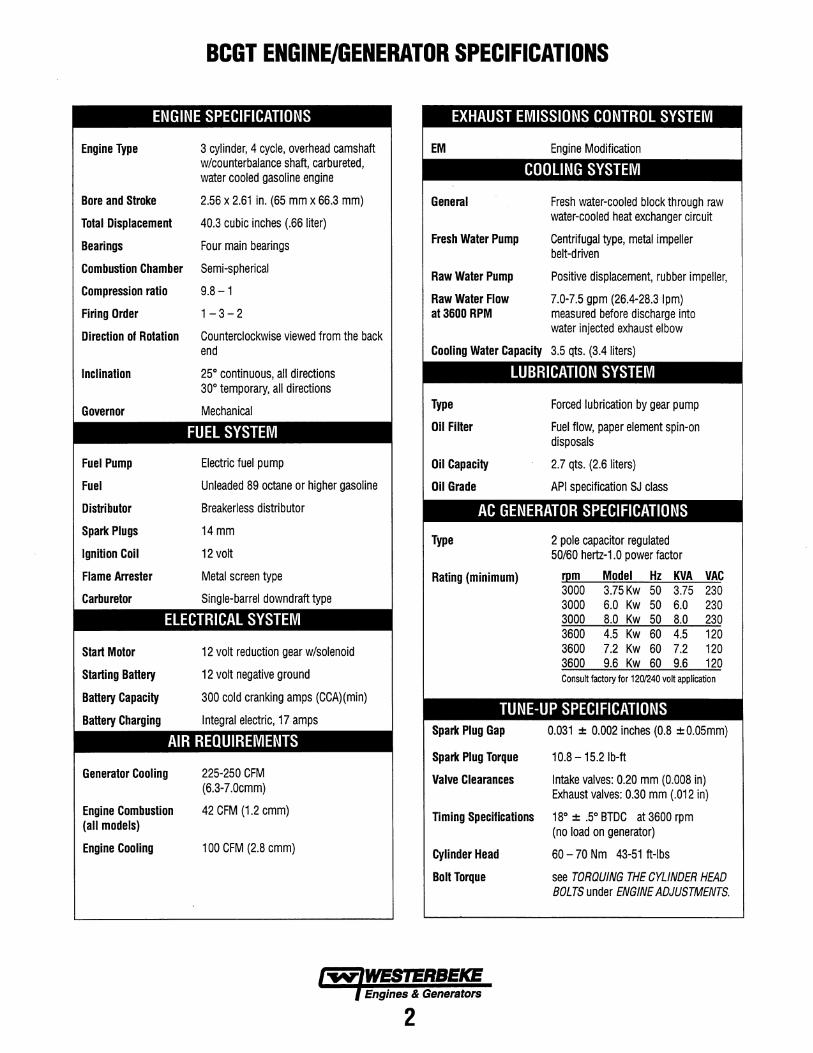
BCGT ENGINE/GENERATOR SPECIFICATIONS
ENGINE SPECIFICATIONS
Engine Type 3 cylinder, 4 cycle, overhead camshaft w/counterbalance shaft, carbureted, water cooled gasoline engine
Bore and Stroke 2.56 x 2.61 in. (65 mm x 66.3 mm)
Total Displacement 40.3 cubic inches (.66 liter)
Bearings Four main bearings
Combustion Chamber Semi-spherical
Compression ratio 9.8 - 1
Firing Order 1 - 3 - 2
Direction of Rotation Counterclockwise viewed from the back end
Inclination
Governor
Fuel Pump
Fuel
Distributor
Spark Plugs
Ignition Coil
Flame Arrester
Carburetor
25° continuous, all directions 30° temporary, all directions
Mechanical
FUEL SYSTEM
Electric fuel pump
Unleaded 89 octane or higher gasoline
Breakerless distributor
14mm
12 volt
Metal screen type
Single-barrel downdraft type
ELECTRICAL SYSTEM
Start Motor
Starting Battery
Battery Capacity
Battery Charging
12 volt reduction gear w/solenoid
12 volt negative ground
300 cold cranking amps (CCA)(min)
Integral electric, 17 amps
AIR REQUIREMENTS
Generator Cooling
Engine Combustion (all models)
Engine Cooling
225-250 CFM (6.3-7.0cmm)
42 CFM (1.2 cmm)
100 CFM (2.8 cmm)
General
Fresh Water Pump
Raw Water Pump
Raw Water Flow at 3600 RPM
Fresh water-cooled block through raw water-cooled heat exchanger circuit
Centrifugal type, metal impeller belt-driven
Positive displacement, rubber impeller,
7.0-7.5 gpm (26.4-28.3 Ipm) measured before discharge into water injected exhaust elbow
Cooling Water Capacity 3.5 qts. (3.4 liters)
LUBRICATION SYSTEM
Type
Oil Filter
Oil Capacity
Oil Grade
Forced lubrication by gear pump
Fuel flow, paper element spin-on disposals
2.7 qts. (2.6 liters)
API specification SJ class
AC GENERATOR SPECIFICATIONS
Type 2 pole capacitor regulated 50/60 hertz-1.0 power factor
Rating (minimum) r~m Model Hz KVA 3000 3.75Kw 50 3.75 3000 6.0 Kw 50 6.0 3000 8.0 Kw 50 8.0 3600 4.5 Kw 60 4.5 3600 7.2 Kw 60 7.2 3600 9.6 Kw 60 9.6
VAC 230 230 230 120 120 120
Consult factory for 1201240 volt application
TUNE-UP SPECIFICATIONS Spark Plug Gap
Spark Plug Torque
0.031 ± 0.002 inches (0.8 ± 0.05mm)
10.8 - 15.2 Ib-ft
Valve Clearances Intake valves: 0.20 mm (0.008 in) Exhaust valves: 0.30 mm (.012 in)
Timing Specifications 18° ± .5° BTDC at 3600 rpm (no load on generator)
Cylinder Head 60 - 70 Nm 43-51 ft-Ibs
Bolt Torque see TORQUING THE CYLINDER HEAD BOLTS under ENGINE ADJUSTMENTS.
Engines & Generators
2
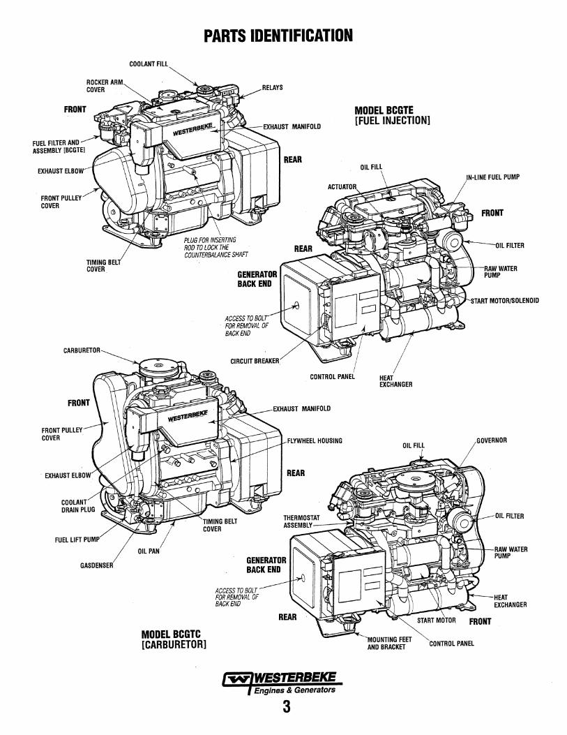
FRONT
FUEL FIlTER ANO ASSEMBLY [BCGTE]
FRONT PUllEY COVER
ROCKER ARM COVER
TIMING BELT COVER
CARBURETOR
FRONT PUllEY COVER
. EXHAUST ELBOW
COOLANT ORAIN PLUG
FUEl LIFT PUMP
GASDENSER
COOLANT Fill
PARTS IDENTIFICATION
RELAYS
GENERATOR BACK END
ACCESS TO BOLT FOR REMOVAL OF BACKEND
CIRCUIT BREAKER.
REAR
MODEL BCGTE [FUEL INJECTION]
Oil Fill
I
IN-LINE FUEL PUMP
FRONT
Oil FilTER
RAW WATER PUMP
CONTROL PANEL HEAT EXCHANGER
Oil PAN
MODEL BCGTC [CARBURETOR]
EXHAUST MANIFOlO
GENERATOR BACK END
ACCESS TO BOLT FOR REMOVAL OF BACK END
FlYWHEEL HOUSING
Engines & Generators
3
Oil Fill
'MOUNTING FEET AND BRACKET CONTROL PANEl
GOVERNOR
Oil FilTER
RAW WATER PUMP
HEAT EXCHANGER
TESTING FOR OVERHAUL HOW TO DETERMINE ENGINE OVERHAUL PERIOD Cause of Low Compression Generally, the time at which an engine should be overhauled is determined by various conditions such as lowered engine power output, decreased compression pressure, and increased fuel and oil consumption. The lowered engine power output is not necessarily due to trouble with the engine itself, but is sometimes caused by improper oil, clogged filters or a faulty carburetor.
The decrease in compression pressure is caused by many factors. It is, therefore, necessary to determine a cause or causes on the basis of data produced by periodic inspection and maintenance. Oil analysis on a seasonal basis is a good means of monitoring engine internal wear. When caused by worn cylinders or piston rings, the following symptoms will occur:
1 Low engine power output 2 Increased fuel consumption 3 Increased oil consumption 4 Hard engine starting 5 Noisy engine operation
These symptoms often appear together. Symptoms 2 and 4 can result also from improper fuel regulation or a faulty carburetor. They are caused also by defective electrical devices such as the battery, starter or spark plugs. Therefore it is desirable to judge the optimum engine overhaul time by the lowered compression pressure caused by worn cylinders and pistons plus increased oil consumption. Satisfactory combustion is obtained only under sufficient compression pressure. If an engine lacks compression pressure, incomplete combustion of fuel will take place even if other parts of the engine are operating properly. To determine the period of engine overhaul, it is important to measure the engine compression pressure regularly. At the same time, the engine speed at which the measurement of compression pressure is made should be checked because the compression pressure varies with engine rpm. The engine rpm can be measured at the front end of the crankshaft.
NOTE: To test engine compression see the ENGINE ADJUSTMENT section of this manual.
OVERHAUL CONDITIONS Compression pressure tends to increase a little in a new engine until piston rings and valve seats have been broken in. Thereafter, it decreases gradually with the progress of wear of these parts.
When decrease of compression pressure reaches the repair limit, the engine must be overhauled.
The engine requires overhaul when oil consumption is high, blowby evident, and compression values are at minimum or below. Engine compression should be 178 psi (1260 Kpa) at 400 rpm. With a limit 137 psi (860 Kpa). Pressure should not differ by more than 14 psi (100 Kpa) between cylinders. See ENGINE COMPRESSION in this manual.
ENGINE OVERHAUL The following sections contain detailed information relating to the major components and systems of the engine. Included are disassembly and inspection instructions for the guidance of suitable equipped and staffed marine engine service and rebuilding facilities. The necessary procedures should be undertaken only by such facilities.
Additional detailed information and specifications are provided in other sections of this manual, covering the generator, alternator, starter motor, engine adjustments, cooling pumps, etc.
DISASSEMBLY 1. Before disassembly and cleaning, carefully check for
defects which cannot be found after disassembly and cleaning.
2. Clean the engine exterior.
3. Perform disassembly in a proper order using proper tools. Keep disassembled parts in order. Apply oil when necessary. Take special care to keep the fuel system parts from . intrusion of dust and dirt.
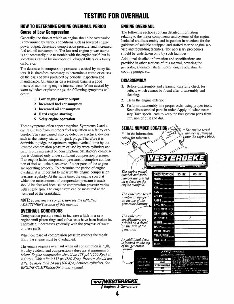
SERIAL NUMBER LOCATION~' ~ The engine serial Fill in the information 1'~0~oo')... 0\, ,:umber is st~mfJed below for reference. .I ,?? \ mto the engzne block.
lY /-~~ ~i ~ ~'\\\ A'",(~ ?~ ,
! ~I' ~~~"'iiijiiijiiiiiliiiiiiiiiiiiiiiiiiiijiij~ I 1
I. 1\ ~~~~~~~ The ~ngin~ mo~el number and serial number are printed on a decal on the engine manifold.
The generator serial number is stamped on the top generator nm',o",o
sDl~citicatiOJ'1s are pnnted on a decal on the side of the generator.
An additional decal is located on the top of the generator liousing.
Engines & Generators
4
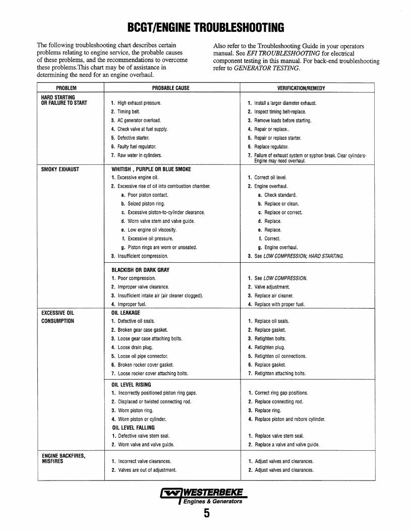
BCGT /ENGINE TROUBLESHOOTING The following troubleshooting chart describes certain problems relating to engine service, the probable causes of these problems, and the recommendations to overcome these problems.This chart may be of assistance in determining the need for an engine overhaul.
PROBLEM PROBABLE CAUSE
HARD STARTING OR FAILURE TO START 1. High exhaust pressure.
2. Timing belt.
3. AC generator overload.
4. Check valve at fuel supply.
5. Defective starter.
6. Faulty fuel regulator.
7. Raw water in cylinders.
SMOKY EXHAUST WHITISH • PURPLE OR BLUE SMOKE 1. Excessive engine oil.
2. Excessive rise of oil into combustion chamber.
3. Poor piston contact.
b. Seized piston ring.
c. Excessive piston-to-cylinder clearance.
d. Worn valve stem and valve guide.
e. Low engine oil viscosity.
I. Excessive oil pressure.
g. Piston rings are worn or unseated.
3. Insufficient compression.
BLACKISH OR DARK GRAY 1. Poor compression.
2. I mproper valve clearance.
3. Insufficient intake air (air cleaner clogged).
4. I mproper fuel.
EXCESSIVE OIL OIL LEAKAGE CONSUMPTION 1. Defective oil seals.
2. Broken gear case gasket.
3. Loose gear case attaching bolts.
4. Loose drain plug.
5. Loose oil pipe connector.
6. Broken rocker cover gasket.
7. Loose rocker cover attaching bolts.
OIL LEVEL RISING 1. Incorrectly positioned piston ring gaps.
2. Displaced or twisted connecting rod.
3. Worn piston ring.
4. Worn piston or cylinder.
OIL LEVEL FALLING 1. Defective valve stem seal.
2. Worn valve and valve guide.
ENGINE BACKFIRES, MISFIRES 1. I ncorrect valve clearances.
2. Valves are out of adjustment.
Also refer to the Troubleshooting Guide in your operators manual. See EFI TROUBLESHOOTING for electrical component testing in this manual. For back-end troubleshooting refer to GENERATOR TESTING.
VERIFICATION/REMEDY
1. Install a larger diameter exhaust.
2. Inspect timing belt-replace.
3. Remove loads before starting.
4. Repair or replace ..
5. Repair or replace starter.
6. Replace regulator.
7. Failure of exhaust system or syphon break. Clear cylinders-Engine may need overhaul.
1. Correct oil level.
2. Engine overhaul.
3. Check standard.
b. Replace or clean.
c. Replace or correct.
d. Replace.
e. Replace.
I. Correct.
g. Engine overhaul.
3. See LOW COMPRESSION; HARD STARTING.
1. See LOW COMPRESSION.
2. Valve adjustment.
3. Replace air cleaner.
4. Replace with proper fuel.
1. Replace oil seals.
2. Replace gasket.
3. Retighten bolts.
4. Retighten plug.
5. Retighten oil connections.
6. Replace gasket.
7. Retighten attaching bolts.
1. Correct ring gap positions.
2. Replace connecting rod.
3. Replace ring.
4. Replace piston and rebore cylinder.
1. Replace valve stem seal.
2. Replace a valve and valve guide.
1. Adjust valves and clearances.
2. Adjust valves and clearances.
Engines & Generators
5
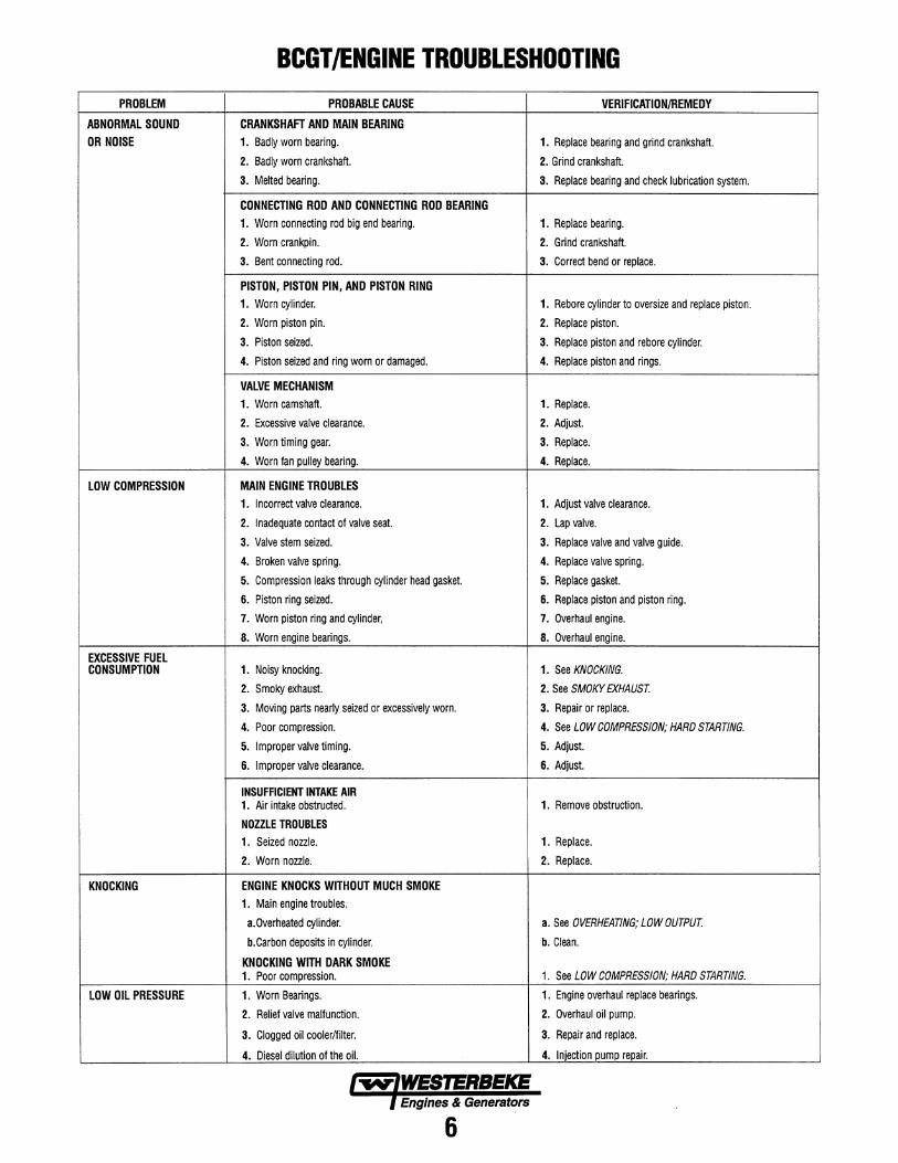
BCGT /ENGINE TROUBLESHOOTING PROBLEM PROBABLE CAUSE VERIFICATION/REMEOY
ABNORMAL SOUND CRANKSHAFT AND MAIN BEARING
OR NOISE 1. Badly worn bearing. 1. Replace bearing and grind crankshaft.
2. Badly worn crankshaft. 2. Grind crankshaft.
3. Melted bearing. 3. Replace bearing and check lubrication system.
CONNECTING ROD AND CONNECTING ROD BEARING 1. Worn connecting rod big end bearing. 1. Replace beari ng.
2. Worn crankpin. 2. Grind crankshaft.
3. Bent connecting rod. 3. Correct bend or replace.
PISTON, PISTON PIN, AND PISTON RING 1. Worn cylinder. 1. Rebore cylinder to oversize and replace piston.
2. Worn piston pin. 2. Replace piston.
3. Piston seized. 3. Replace piston and rebore cylinder.
4. Piston seized and ring worn or damaged. 4. Replace piston and rings.
VALVE MECHANISM 1. Worn camshaft. 1. Replace.
2. Excessive valve clearance. 2. Adjust.
3. Worn timing gear. 3. Replace.
4. Worn fan pulley bearing. 4. Replace.
LOW COMPRESSION MAIN ENGINE TROUBLES 1. Incorrect valve clearance. 1. Adjust valve clearance.
2. Inadequate contact of valve seat. 2. Lap valve.
3. Valve stem seized. 3. Replace valve and valve guide.
4. Broken valve spring. 4. Replace valve spring.
5. Compression leaks through cylinder head gasket. 5. Replace gasket.
6. Piston ring seized. 6. Replace piston and piston ring.
7. Worn piston ring and cylinder, 7. Overhaul engine.
8. Worn engine bearings. 8. Overhaul engine.
EXCESSIVE FUEL CONSUMPTION 1. Noisy knocking. 1. See KNOCKING.
2. Smoky exhaust. 2. See SMOKY EXHAUST.
3. Moving parts nearly seized or excessively worn. 3. Repair or replace.
4. Poor compression. 4. See LOW COMPRESSION; HARD STARTING.
5. Improper valve timing. 5. Adjust.
6. Improper valve clearance. 6. Adjust.
INSUFFICIENT INTAKE AIR 1. Air intake obstructed. 1. Remove obstruction.
NOZZLE TROUBLES 1. Seized nozzle. 1. Replace.
2. Worn nozzle. 2. Replace.
KNOCKING ENGINE KNOCKS WITHOUT MUCH SMOKE 1. Main engine troubles.
a.Overheated cylinder. a. See OVERHEATING; LOW OUTPUT.
b.Carbon deposits in cylinder. b. Clean.
KNOCKING WITH DARK SMOKE 1. Poor compression. 1. See LOW COMPRESSION; HARD STARTING.
LOW OIL PRESSURE 1. Worn Bearings. 1. Engine overhaul replace bearings.
2. Relief valve malfunction. 2. Overhaul oil pump.
3. Clogged oil cooler/filter. 3. Repair and replace.
4. Diesel dilution of the oil. 4. Injection pump repair.
Engines & Generators
6
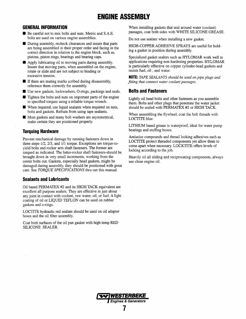
ENGINE ASSEMBLY GENERAL INFORMATION • Be careful not to mix bolts and nuts. Metric and S.A.E.
bolts are used on various engine assemblies.
• During assembly, recheck clearances and insure that parts are being assembled in their proper order and facing in the correct direction in relation to the engine block, such as, pistons, piston rings, bearings and bearing caps.
• Apply lubricating oil to moving parts during assembly. Insure that moving parts, when assembled on the engine, rotate or slide and are not subject to binding or excessive tension.
• If there are mating marks scribed during disassembly, reference them correctly for assembly.
• Use new gaskets, lockwashers, O-rings, packings and seals.
• Tighten the bolts and nuts on important parts of the engine to specified torques using a reliable torque wrench.
• When required, use liquid sealants when required on nuts, bolts and gaskets. Refrain from using tape sealants.
• Most gaskets and many bolt washers are asymmetrical, make certain they are positioned properly.
Torquing Hardware Prevent mechanical damage by running fasteners down in three steps-I/2, 2/3, and 111 torque. Exceptions are torque-toyield bolts and rocker arm shaft fasteners. The former are torqued as indicated. The latter-rocker shaft fasteners-should be brought down in very small increments, working from the center bolts out. Gaskets, especially head gaskets, might be damaged during assembly, they should be positioned with great care. See TORQUE SPECIFICATIONS thru out this manual.
Sealants and Lubricants Oil based PERMATEX #2 and its HIGH TACK equivalent are excellent all purpose sealers. They are effective in just about . any joint in contact with coolant, raw water, oil, or fuel. A light coating of oil or LIQUID TEFLON can be used on rubber gaskets and o-rings.
LOCTITE hydraulic red sealant should be used on oil adapter hoses and the oil filter assembly.
Coat both surfaces of the oil pan gasket with high temp RED SILICONE SEALER.
When installing gaskets that seal around water (coolant) passages, coat both sides with WHITE SILICONE GREASE.
Do not use sealant when installing a new gasket.
HIGH-COPPER ADHESIVE SPRAYS are useful for holding a gasket in position during assembly.
Specialized gasket sealers such as HYLOMAR work well in applications requiring non-hardening properties. HYLOMAR is particularly effective on copper cylinder-head gaskets and resists fuel, oil , and water.
NOTE: TAPE SEALANTS should be used on pipe plugs and fitting that connect water coolant passages.
Bolts and Fasteners Lightly oil head bolts and other fasteners as you assemble them. Bolts and other plugs that penetrate the water jacket should be sealed with PERMATEX #2 or HIGH TACK.
When assembling the flywheel, coat the bolt threads with LOCTITE blue.
LITHIUM based grease is waterproof, ideal for water pump bearings and stuffing boxes.
Antiseize compounds and thread locking adhesives such as LOCTITE protect threaded components yet allow them to come apart when necessary. LOCKTITE offers levels of locking according to the job.
Heavily oil all sliding and reciprocating components, always use clean engine oil.
Engines & Generators
7
GENERATOR DISASSEMBLY
STATOR
FRONT
BACK END DISASSEMBLY
GENERATOR
TAPPER EO SHAFT
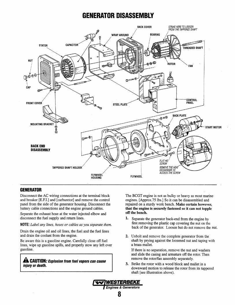
Disconnect the AC wiring connections at the terminal block and breaker [E.EI.] and [carburetor] and remove the control panel from the side of the generator housing. Disconnect the battery cable connections and the engine ground cables.
Separate the exhaust hose at the water injected elbow and disconnect the fuel supply and return lines.
NOTE: Label any lines, hoses or cables as you separate them.
Drain the engine oil and oil lines, the fuel and the fuel lines and drain the coolant from the engine.
Be aware this is a gasoline engine. Carefully close off fuel lines, wipe up gasoline spills, and properly stow any left over gasoline.
A CAUTION: Explosion from fuel vapors can cause injury or death.
BACK COVER STRIKE HERE TO LOOSEN FROM THE TAPPERED SHAFT
FLATHD. SCREW REMOVE THE HEAT EXCHANGER TO ACCESS THE SCREW
FAN
The BCGT engine is not as bulky or heavy as most marine engines. [Approx.75Ibs.] So it can be disassembled and repaired on a sturdy work bench. Make certain however, that the engine is securely fastened so it can not topple off the bench.
1. Separate the generator back-end from the engine by first removing the plastic cap covering the nut on the back of the generator. Loosen but do not remove the nut.
2. Unbolt and remove the complete generator from the shaft by prying against the loosened nut and taping with a brass mallet.
If there is no separation, remove the nut and washers and slide the casing and armature off the rotor. Then remove the rotor/fan assembly separately.
3. Strike the rotor with a wood block and mallet in a downward motion to release the rotor from its tappered shaft [see illustration above).
Engines & Generators
8
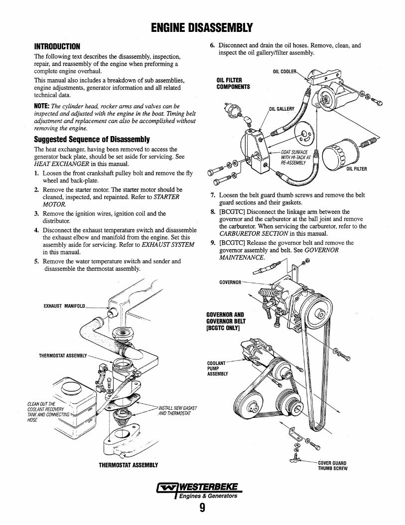
ENGINE DISASSEMBLY INTRODUCTION The following text describes the disassembly, inspection, repair, and reassembly of the engine when preforming a complete engine overhaul. This manual also includes a breakdown of sub assemblies, engine adjustments, generator information and all related technical data.
NOTE: The cylinder head, rocker arms and valves can be inspected and adjusted with the engine in the boat. TIming belt adjustment and replacement can also be accomplished without removing the engine.
Suggested Sequence of Disassembly The heat exchanger, having been removed to access the generator back plate, should be set aside for servicing. See HEAT EXCHANGER in this manual. 1. Loosen the front crankshaft pulley bolt and remove the fly
wheel and back-plate. 2. Remove the starter motor. The starter motor should be
cleaned, inspected, and repainted. Refer to STARTER MOTOR.
3. Remove the ignition wires, ignition coil and the distributor.
4. Disconnect the exhaust temperature switch and disassemble the exhaust elbow and manifold from the engine. Set this assembly aside for servicing. Refer to EXHAUST SYSTEM in this manual.
5. Remove the water temperature switch and sender and disassemble the thermostat assembly.
THERMOSTAT ASSEMBLY
6. Disconnect and drain the oil hoses. Remove, clean, and inspect the oil gallery/filter assembly.
OIL FILTER COMPONENTS
OIL COOLER
(jjd.~ \\.
OIL FILTER
7. Loosen the belt guard thumb screws and remove the belt guard sections and their gaskets.
8. [BCGTC] Disconnect the linkage arm between the governor and the carburetor at the ball joint and remove the carburetor. When servicing the carburetor, refer to the CARBURETOR SECTION in this manual.
9. [BCGTC] Release the governor belt and remove the governor assembly and belt. See GOVERNOR MAINTENANCE. .
GOVERNOR AND GOVERNOR BELT [BCGTC ONLy]
COOLANT PUMP ASSEMBLY
Engines & Generators
9
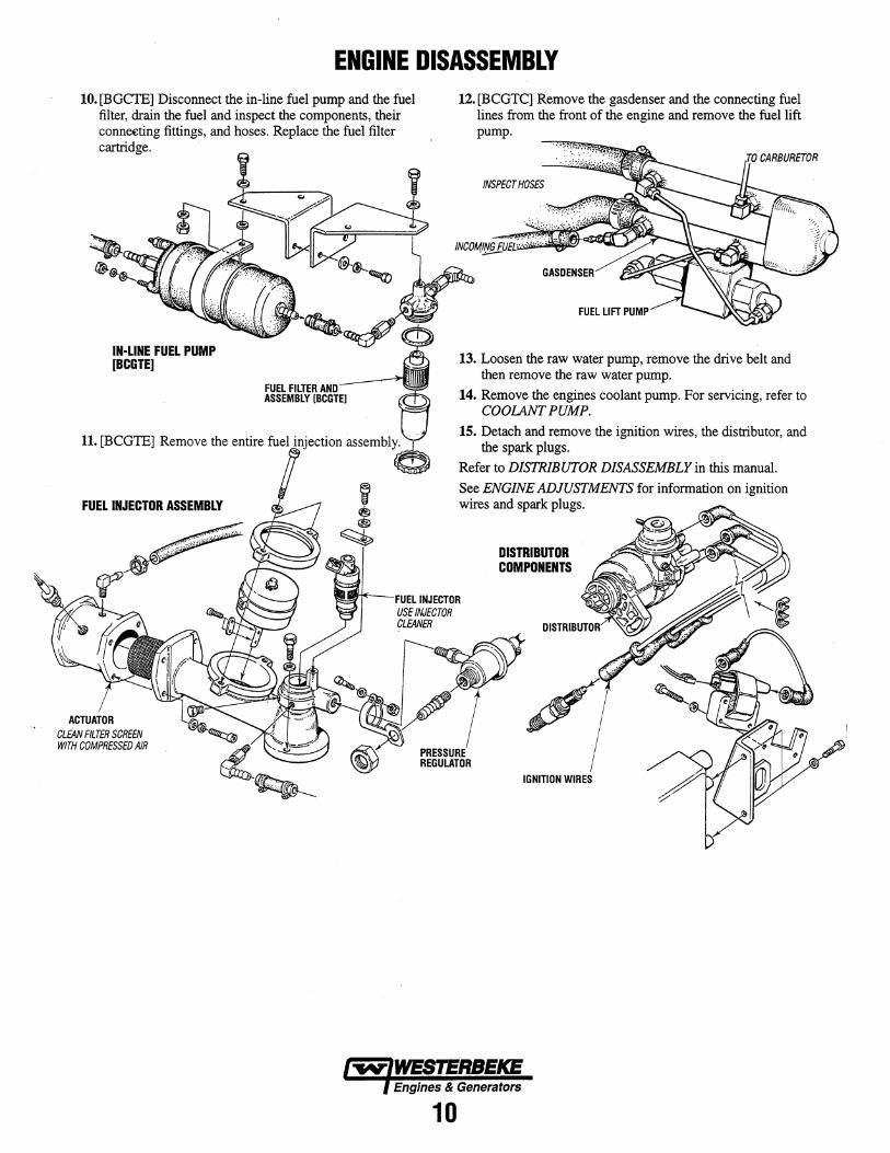
ENGINE DISASSEMBLY 10. [BGCTE] Disconnect the in-line fuel pump and the fuel
filter, drain the fuel and inspect the components, their conneeting fittings, and hoses. Replace the fuel filter cartridge.
IN-LINE FUEL PUMP [BCGTE]
FUEL FILTER AND AS'EMBLY"CGlE) e
11. [BCGTE] Remove the entire fuel aSSemble
FUEL INJECTOR ASSEMBLY
12. [BCGTC] Remove the gasdenser and the connecting fuel lines from the front of the engine and remove the fuel lift pump.
INSPECT HOSES
13. Loosen the raw water pump, remove the drive belt and then remove the raw water pump.
14. Remove the engines coolant pump. For servicing, refer to COOLANT PUMP.
15. Detach and remove the ignition wires, the distributor, and the spark plugs.
Refer to DISTRIBUTOR DISASSEMBLY in this manual.
See ENGINE ADJUSTMENTS for information on ignition wires and spark plugs.
DISTRIBUTOR COMPONENTS
FUEL INJECTOR USE INJECTOR CLEANER
IGNITION WIRES
Engines & Generators
10
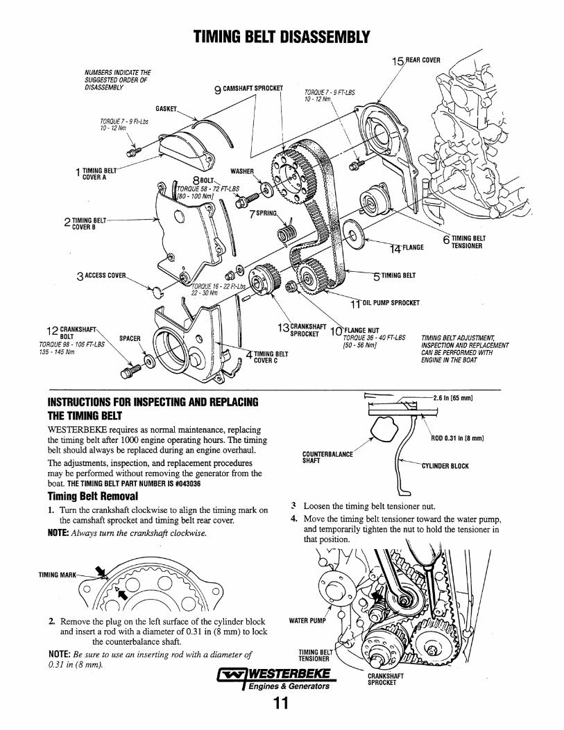
TIMING BELT DISASSEMBLY
NUMBERS INDICATE THE SUGGESTED ORDER OF DISASSEMBLY 9 CAMSHAFT SPROCKET
12 BOLT
1 TIMING COVER A
3 ACCESS COVER~
TORQUE 98 - 105 FT-LBS 135 -145 Nm
INSTRUCTIONS FOR INSPECTING AND REPLACING THE TIMING BELT WES1ERBEKE requires as nonnal maintenance, replacing the timing belt after 1000 engine operating hours. The timing belt should always be replaced during an engine overhaul. The adjustments, inspection, and replacement procedures may be perfonned without removing the generator from the boat. THE TIMING BELT PART NUMBER IS #043036
Timing Belt Removal 1. Turn the crankshaft clockwise to align the timing mark on
the camshaft sprocket and timing belt rear cover. NOTE: Always tum the crankshaft clockwise.
TIMING MARK_=:,;;;~v~,....,
2. Remove the plug on the left surface of the cylinder block and insert a rod with a diameter of 0.31 in (8 mm) to lock
the counterbalance shaft. NOTE: Be sure to use an inserting rod with a diameter of 0.31 in (8 mm).
BELT C
TIMING BELT TENSIONER
TIMING BELT ADJUSTMENT, INSPECTION AND REPLACEMENT CAN BE PERFORMED WITH ENGINE IN THE BOAT
~----':2.6 In 165 mmJ ~-~~
ROO 0.31 In [8 mmJ
~ Loosen the timing belt tensioner nut. 4. Move the timing belt tensioner toward the water pump,
and temporarily tighten the nut to hold the tensioner in that position.
Engines & Generators CRANKSHAFT SPROCKET
11
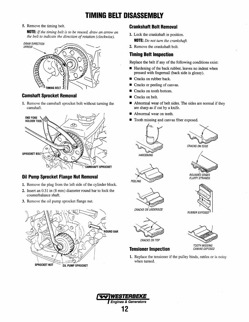
TIMING BELT DISASSEMBLY 5. Remove the timing belt.
NOTE: If the timing belt is to be reused, draw an arrow on the belt to indicate the direction of rotation (clockwise).
Camshaft Sprocket Removal 1. Remove the camshaft sprocket bolt without turning the
camshaft.
SPROCKET BOLT
Oil Pump Sprocket Flange Nut Removal 1. Remove the plug from the left side of the cylinder block.
2. Insert an 0.31 in (8 mm) diameter round bar to lock the counterbalance shaft.
3. Remove the oil pump sprocket flange nut.
SPROCKET NUT OIL PUMP SPROCKET
Crankshaft Bolt Removal 1. Lock the crankshaft in position.
NOTE: Do not tum the crankshaft.
2. Remove the crankshaft bolt.
Timing Belt Inspection Replace the belt if any of the following conditions exist:
• Hardening of the back rubber, leaves no indent when pressed with fingernail (back side is glossy).
• Cracks on rubber back.
• Cracks or peeling of canvas.
• Cracks on tooth bottom.
• Cracks on belt.
• Abnormal wear of belt sides. The sides are normal if they are sharp as if cut by a knife.
• Abnormal wear on teeth.
• Tooth missing ~d canvas fiber exposed.
HARDENING
~ 'v. ~ (' 00
PEELING 00
$ CRACKS ON UNDERSIZE
CRACKS ON TOP
Tensioner Inspection
-, ~ ~ CRACKS ON EDGE
~,~\'.:", ~'" ~ .. ,
ROUNDED EDGES FLUFFY STRANDS
TOOTH MISSING CANVAS EXPOSED
1. Replace the tensioner if the pulley binds, rattles or is noisy when turned.
Engines & Generators
12
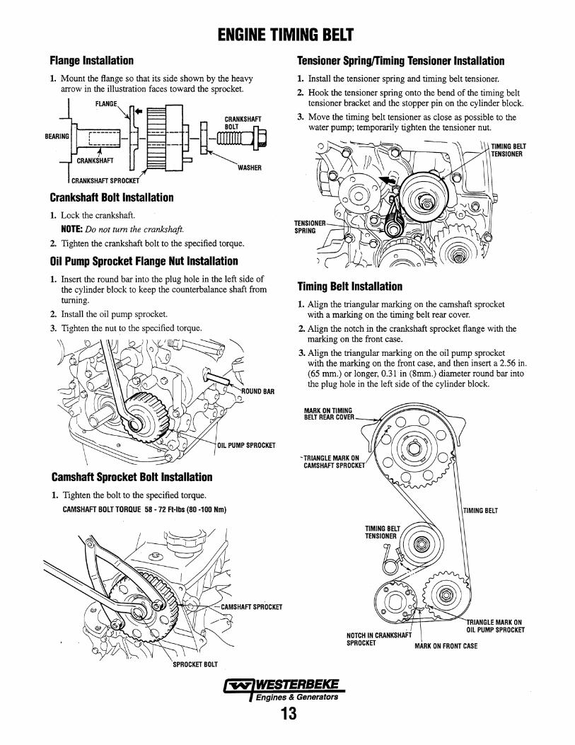
ENGINE TIMING BELT Flange Installation 1. Mount the flange so that its side shown by the heavy
arrow in the illustration faces toward the sprocket.
FLANGE
fi __ ~NKSHAFT
-~ WASHER
Crankshaft Bolt Installation 1. Lock the crankshaft.
NOTE: Do not tum the crankshaft.
2. Tighten the crankshaft bolt to the specified torque.
Oil Pump Sprocket Flange Nut Installation 1. Insert the round bar into the plug hole in the left side of
the cylinder block to keep the counterbalance shaft from turning.
2. Install the oil pump sprocket.
3. Tighten the nut to the specified torque.
Camshaft Sprocket Bolt Installation 1. Tighten the bolt to the specified torque.
CAMSHAFT BOLT TORQUE 58 -72 Ft-Ibs (80 -100 Nm)
SPROCKET BOLT
Tensioner Spring/Timing Tensioner Installation 1. Install the tensioner spring and timing belt tensioner.
2. Hook the tensioner spring onto the bend of the timing belt tensioner bracket and the stopper pin on the cylinder block.
3. Move the timing belt tensioner as close as possible to the water pump; temporarily tighten the tensioner nut.
Timing Belt Installation 1. Align the triangular marking on the camshaft sprocket
with a marking on the timing belt rear cover.
2. Align the notch in the crankshaft sprocket flange with the marking on the front case.
3. Align the triangular marking on the oil pump sprocket with the marking on the front case, and then insert a 2.56 in. (65 mm.) or longer, 0.31 in (Smm.) diameter round bar into the plug hole in the left side of the cylinder block.
MARK ON TIMING BELT REAR COVER_--"'''A
- TRIANGLE MARK ON CAMSHAFT SPROCKET
~d~=\=~====i"'C-..TRIANGLE MARK ON
NOTCH IN CRANKSHAFT SPROCKET
OIL PUMP SPROCKET
MARK ON FRONT CASE
Engines & Generators
13
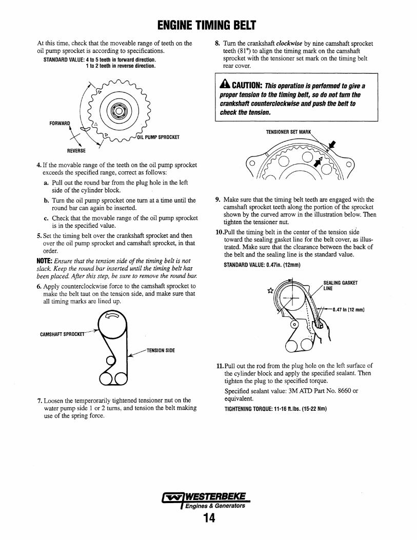
ENGINE TIMING BELT At this time, check that the moveable range of teeth on the oil pump sprocket is according to specifications.
STANDARD VALUE: 4 to 5 teeth in forward direction. 1 to 2 teeth in reverse direction.
4. If the movable range of the teeth on the oil pump sprocket exceeds the specified range, correct as follows:
a. Pull out the round bar from the plug hole in the left side of the cylinder block.
b. Turn the oil pump sprocket one turn at a time until the round bar can again be inserted.
c. Check that the movable range of the oil pump sprocket is in the specified value.
5. Set the timing belt over the crankshaft sprocket and then over the oil pump sprocket and camshaft sprocket, in that order.
NOTE: Ensure that the tension side of the timing belt is not slack. Keep the round bar inserted until the timing belt has been placed. After this step, be sure to remove the round bar.
6. Apply counterclockwise force to the camshaft sprocket to make the belt taut on the tension side, arid make sure that all timing marks are lined up.
CAMSHAFT SPROCKET
TENSION SIDE
7. Loosen the temperorarily tightened tensioner nut on the water pump side 1 or 2 turns, and tension the belt making use of the spring force.
8. Turn the crankshaft clockwise by nine camshaft sprocket teeth (81°) to align the timing mark on the camshaft sprocket with the tensioner set mark on the timing belt rear cover.
A CAUTION: This operation is perfonned to give a proper tension to the timing belt, so do not tum the crankshaft counterclockwise and push the belt to check the tension.
TENSIONER SET MARK
9. Make sure that the timing belt teeth are engaged with the camshaft sprocket teeth along the portion of the sprocket shown by the curved arrow in the illustration below. Then tighten the tensioner nut.
IO.Pull the timing belt in the center of the tension side toward the sealing gasket line for the belt cover, as illustrated. Make sure that the clearance between the back of the belt and the sealing line is the standard value.
STANDARD VALUE: O.47in. (12mm)
0.47 In [12 mm]
1l.Pull out the rod from the plug hole on the left surface of the cylinder block and apply the specified sealant. Then tighten the plug to the specified torque.
Specified sealant value: 3M AID Part No. 8660 or equivalent.
TIGHTENING TDRQUE: 11-16 fUbs. (15-22 Nm)
Engines & Generators
14
CYLINDER HEAD AND VALVES
4 CYLINDER HEAD. TORQUE 43 - 51 FT-LBS 60-70Nm
13
~-----14
8
9 VALVE SEAL
1 o VALVE
19VAlVE GUIDE
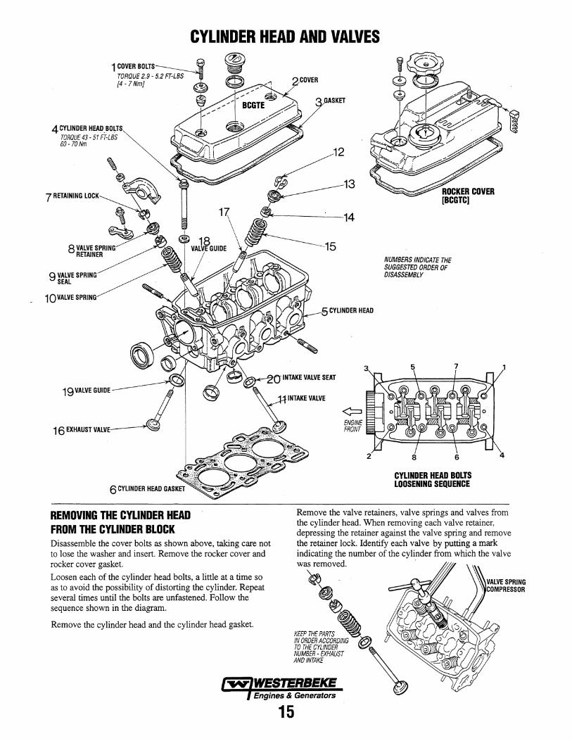
REMOVING THE CYLINDER HEAD FROM THE CYLINDER BLOCK Disassemble the cover bolts as shown above, taking care not to lose the washer and insert. Remove the rocker cover and rocker cover gasket.
Loosen each of the cylinder head bolts, a little at a time so as to avoid the possibility of distorting the cylinder. Repeat several times until the bolts are unfastened. Follow the sequence shown in the diagram.
Remove the cylinder head and the cylinder head gasket.
HEAD
¢::I ENGINE FRONT
NUMBERS INDICATE THE SUGGESTED ORDER OF DISASSEMBLY
8 6
CYLINDER HEAD BOLTS LOOSENING SEQUENCE
Remove the valve retainers, valve springs and valves from the cylinder head. When removing each valve retainer, depressing the retainer against the valve spring and remove the retainer lock. Identify each valve by putting a mark
~';;:~:: numbe>- of the cyfuJrler ~ which the valve
, KEEP THE PARTS '\ IN OROER ACCOROING TO THE CYLINDER NUMBER - EXHAUST ANOINTAKE
Engines & Generators
15
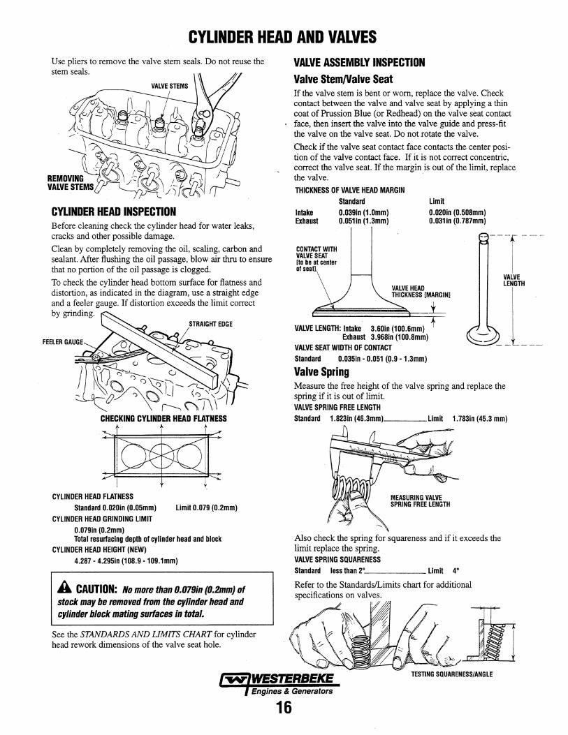
CYLINDER HEAD AND VALVES Use pliers to remove the valve stem seals. Do not reuse the stem seals.
CYLINDER HEAD INSPECTION Before cleaning check the cylinder head for water leaks, cracks and other possible damage.
Clean by completely removing the oil, scaling, carbon and sealant. After flushing the oil passage, blow air thru to ensure that no portion of the oil passage is clogged.
To check the cylinder head bottom surface for flatness and distortion, as indicated in the diagram, use a straight edge and a feeler gauge. If distortion exceeds the limit correct by grinding.
CHECKING CYLINDER HEAD FLATNESS
CYLINDER HEAD FLATNESS Standard 0.020in (0.05mm)
CYLINDER HEAD GRINDING LIMIT 0.079in (0.2mm)
Limit 0.079 (0.2mm)
Total resurfacing depth of cylinder head and block CYLINDER HEAD HEIGHT (NEW)
4.287 - 4.295in (108.9 -109.1mm)
A CAUTION: No more than O.07Bin (O.2mm) of stock may be removed from the cylinder head and cylinder block mating surfaces in total.
See the STANDARDS AND LIMITS CHART for cylinder head rework dimensions of the valve seat hole.
VALVE ASSEMBLY INSPECTION Valve StemNalve Seat If the valve stem is bent or worn, replace the valve. Check contact between the valve and valve seat by applying a thin coat of Prussion Blue (or Redhead) on the valve seat contact face, then insert the valve into the valve guide and press-fit the valve on the valve seat. Do not rotate the valve.
Check if the valve seat contact face contacts the center position of the valve contact face. If it is not correct concentric, correct the valve seat. If the margin is out of the limit, replace the valve. .
THICKNESS OF VALVE HEAD MARGIN Standard
Intake 0.0391n (1.0mm) Exhaust 0.051in (1.3mm)
Limit 0.020in (0.508mm) 0.031 in (0.787mm)
CONTACT wmi VALVE SEAT [to be al cenler of seat)
----r--VALVE HEAD THICKNESS [MARGIN)
.L VALVE LENGTH: Intake 3.60in (100.6mm)
Exhaust 3.968in (100.8mm) VALVE SEAT WIDTH OF CONTACT Standard 0.035in - 0.051 (p.9 - 1.3mm)
Valve Spring
VALVE LENGTH
Measure the free height of the valve spring and replace the spring if it is out of limit. VALVE SPRING FREE LENGTH Standard 1.823in (46.3mm) ____ Limit 1.783in (45.3 mm)
Also check the spring for squareness and if it exceeds the limit replace the spring. VALVE SPRING SQUARENESS Standard less than 2° ______ Limit 4°
Refer to the StandardslLimits chart for additional
~~)~-b~jl TESTING SQUARENESS/ANGLE
Engines & Generators
16
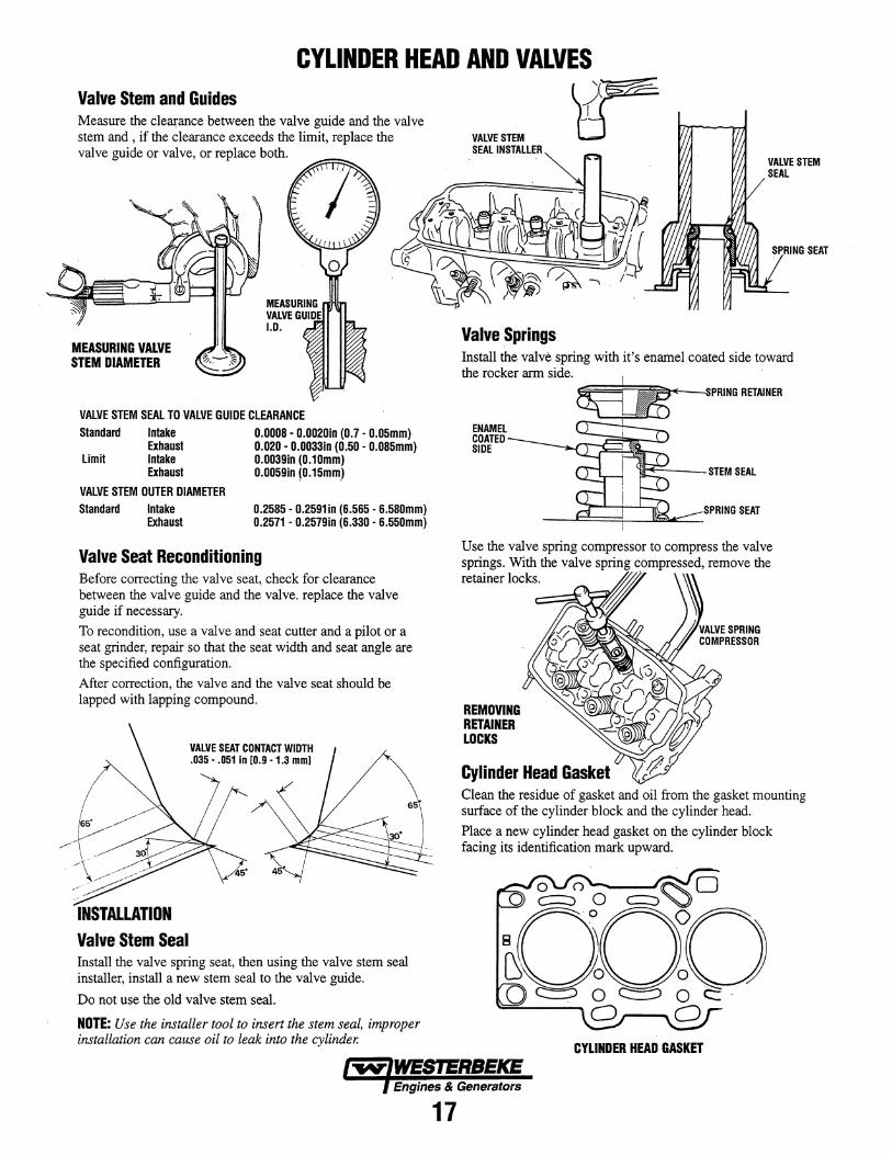
CYLINDER HEAD AND VALVES Valve Stem and Guides Measure the clearance between the valve guide and the valve stem and , if the clearance exceeds the limit, replace the valve guide or valve, or replace both.
MEASURING VALVE STEM DIAMETER
VALVE STEM SEAL TO VALVE GUIDE CLEARANCE Standard
Limit
Intake Exhaust Intake Exhaust
0.0008· 0.0020in (0.7· 0.05mm) 0.020 . 0.0033in (0.50 . 0.085mm) 0.0039in (O.10mm) 0.0059in ~0.15mm)
VALVE STEM OUTER DIAMETER Standard Intake
Exhaust 0.2585· 0.2591in (6.565· 6.580mm) 0.2571 . 0.2579in (6.330 . 6.550mm)
Valve Seat Reconditioning Before correcting the valve seat, check for clearance between the valve guide and the valve. replace the valve guide if necessary.
To recondition, use a valve and seat cutter and a pilot or a seat grinder, repair so that the seat width and seat angle are the specified configuration.
After correction, the valve and the valve seat should be lapped with lapping compound.
. /---- ----/ ~:.~ INSTALLATION Valve Stem Seal
VALVE SEAT CONTACT WIDTH .035 .. 051 in [0.9 . 1.3 mml
InstaII the valve spring seat, then using the valve stem seal installer, install a new stem seal to the valve guide.
Do not use the old valve stem seal.
NOTE: Use the installer tool to insert the stem seal, improper installation can cause oil to leak into the cylinder.
VALVE STEM SEAL INSTALLER
Valve Springs
~ VALVE STEM SEAL
Install the valve spring with it's enamel coated side toward the rocker arm side.
ENAMEL COATED SIDE
1=I"~-o;PRING RETAINER
'H""'i,------.- STEM SEAL
_--.JI::::::::=:::!,.-_.JSiW:::::::::::.. .. SPRING SEAT
Use the valve spring compressor to compress the valve
::.; ::.the vruve "compre~' remove the
REMOVING RETAINER LOCKS
Cylinder Head Gasket Clean the residue of gasket and oil from the gasket mounting surface of the cylinder block and the cylinder head.
Place a new cylinder head gasket on the cylinder block facing its identification mark upward.
CYLINDER HEAD GASKET
Engines & Generators
17
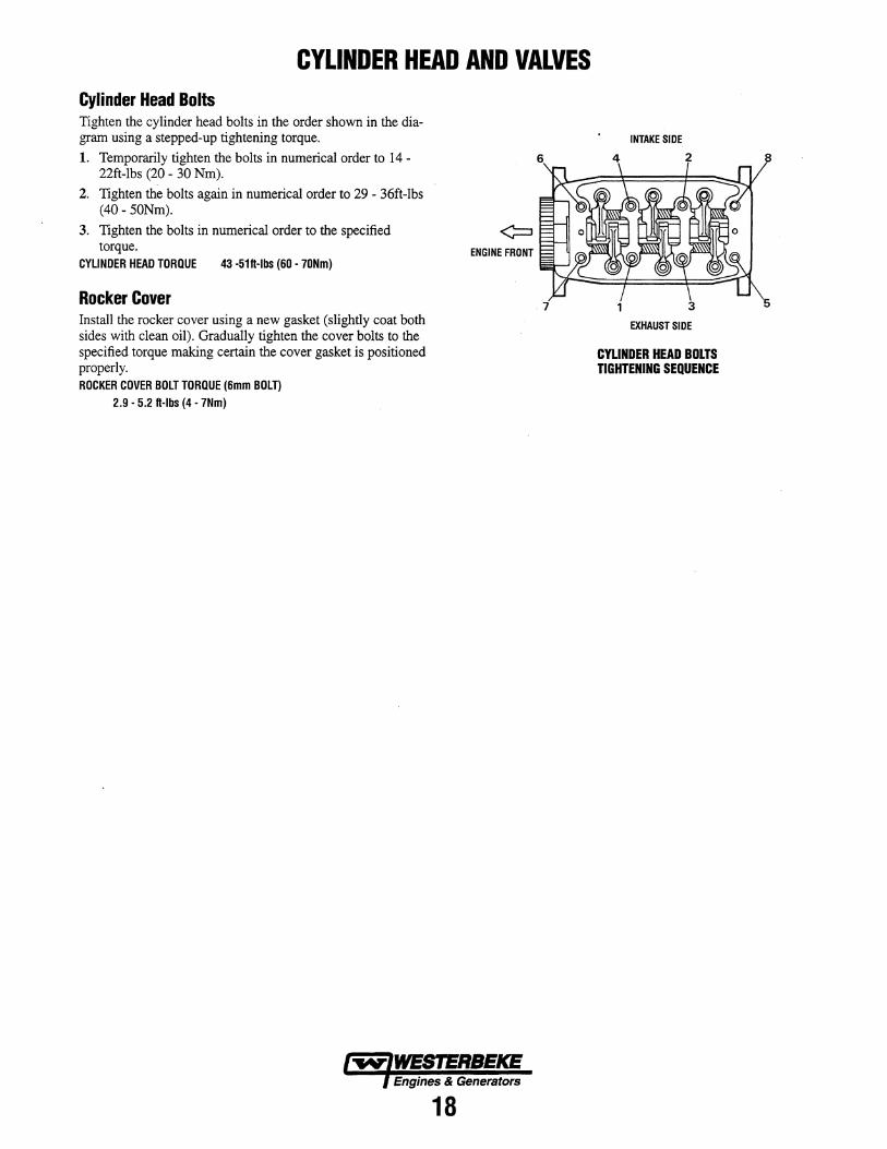
CYLINDER HEAD AND VALVES Cylinder Head Bolts Tighten the cylinder head bolts in the order shown in the diagram using a stepped-up tightening torque.
1. Temporarily tighten the bolts in numerical order to 14 -22ft-Ibs (20 - 30 Nm).
2. Tighten the bolts again in numerical order to 29 - 36ft-Ibs (40 - 50Nm).
3. Tighten the bolts in numerical order to the specified torque.
CYLINDER HEAD TORQUE 43 -51H-lbs (60 - 70Nm)
Rocker Cover Install the rocker cover using a new gasket (slightly coat both sides with clean oil). Gradually tighten the cover bolts to the specified torque making certain the cover gasket is positioned properly. ROCKER COVER BOLT TORQUE (6mm BOLT)
2.9 - 5.2 H-Ibs (4 - 7Nm)
ENGINE FRONT
Engines & Generators
18
7
INTAKE SIDE
2
3
EXHAUST SIDE
CYLINDER HEAD BOLTS TIGHTENING SEQUENCE
CAMSHAFT AND ROCKER ARMS TORQUE 21 - 25 FT-LBS
TORQUE 21 - 25 Ft-Lbs 2! - 35 Nm ~ 21-35Nm ~ ~ NUMBERS INDICATE THE
SUGGESTED ORDER OF DISASSEMBLY
1 0 ROCKER ARM ,.d,... EXHAUST ~
1 ROCKER ARM, ROCKER SHAFT ASSEMBLY
12CAMSHAFT ® OILSEAL ~
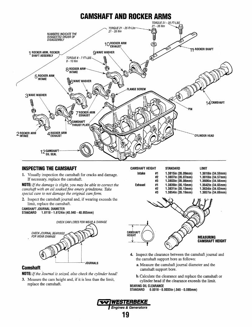
INSPECTING THE CAMSHAFT 1. Visually inspection the camshaft for cracks and damage.
If necessary, replace the camshaft.
NOTE: If the damage is slight, you may be able to correct the camshaft with an oil soakedfine emery grindstone. Take special care to not damage the original cam form.
2. Inspect the camshaft journal and, if wearing exceeds the limit, replace the camshaft.
CAMSHAFT JOURNAL DIAMETER STANDARD 1.6118 ·1.612410 (40.940 - 40.955mm)
CHECK JOURNAL BEARINGS FOR WEAR DAMAGE
Camshaft NOTE: If the journal is seized, also check the cylinder head! 3. Measure the cam height and, if it is less than the limit,
replace the camshaft.
CAMSHAFT HEIGHT lotake #1
#2 #3
Exhaust #1 #2 #3
C:r:-~D' HEIGHT
~.
STANDARD 1.381510 (35.09mm) 1.380710 (35.07mm) 1.380310 (35.06mm) 1.383910 (35.15mm) 1.383110 (35.13mm) 1.385410 (35.19mm)
LIMIT 1.361810 (34.59mm) 1.361010 (34.57mm) 1.360610 (34.56mm) 1.364210 (34.65mm) 1.363410 (34.63mm) 1.365710 (34.69mm)
MEASURING CAMSHAFT HEIGHT
4. Inspect the clearance between the camshaft journal and the camshaft support bore as follows:
a. Measure the camshaft journal diameter and the camshaft support bore.
b. Calculate the clearance and replace the camshaft or cylinder head if the clearance exceeds the limit.
BEARING OIL CLEARANCE STANDARD 0.0018·0.003310 (.045· 0.085mm)
Engines & Generators
19
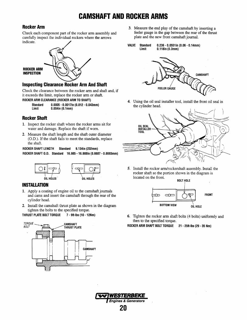
CAMSHAFT AND ROCKER ARMS Rocker Arm Check each component part of the rocker arm assembly and carefully inspect the individual rockers where the arrows indicate.
ROCKER ARM INSPECTION
Inspecting Clearance Rocker Arm And Shaft Check the clearance between the rocker arm and shaft and, if it exceeds the limit, replace the rocker arm or shaft. ROCKER ARM CLEARANCE (ROCKER ARM TO SHAFT)
Standard 0.0005 • O.0017in (0.012 • O.043mm) Limit 0.004in (0.1mm)
Rocker Shaft 1. Inspect the rocker shaft where the rocker arms sit for
water and damage. Replace the shaft if worn.
2. Measure the shaft length and the shaft outer diameter (O.D.). If the shaft fails to meet the standards, replace the shaft.
ROCKER SHAFT LENGTH Standard 9.134in (232mm) ROCKER SHAFT 0.0. Standard 16.985 • 16.988in (0.6687· 0.6693mm)
~ OIL HOLES-
~~II or] OIL HOLES
INSTALLATION 1. Apply a coating of engine oil to the camshaft journals
and cams and insert the camshaft through the rear of the cylinder head.
2. Install the camshaft thrust plate as shown in the diagram tighten the bolts to the specified torque. .
THRUST PLATE BOLT TORQUE 7· 9ft·lbs (10 • 12Nm)
TORQUE BOLT --.... .. ,..,...T\
3. Measure the end play of the camshaft by inserting a feeler gauge in the gap between the rear of the thrust plate and the new front camshaft journal.
VALVE Standard 0.236· 0.0551 in (0.06· 0.14mm) Limit 0.118in (0.3mm)
4. Using the oil seal installer tool, install the front oil seal in the cylinder head.
5. Install the rocker armIrockershaft assembly. Install the rocker shaft so the portion shown in the diagram is located on the front.
BOLT HOLE
FRONT
6. Tighten the rocker arm shaft bolts (4 bolts) uniformly and then to the specified torque.
ROCKER ARM SHAFT BOLT TORQUE 21 • 25ft·lbs (29 ·35 Nm)
Engines & Generators
20
PISTONS AND CONNECTING RODS 111 PISTON RING
112 PISTON RING ARROW FRONT MARK
golLRING ~~ __ v
NUMBERS INDICATE THE SUGGESTED ORDER OF DISASSEMBLY
6 BEARING
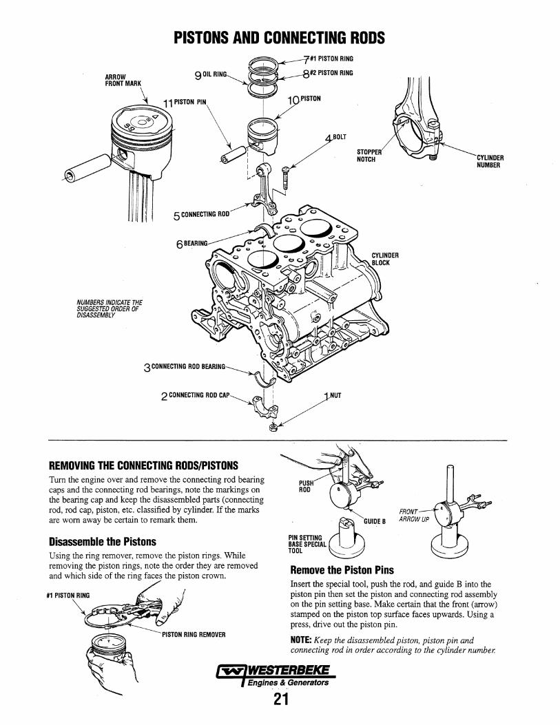
REMOVING THE CONNECTING RODS/PISTONS Turn the engine over and remove the connecting rod bearing caps and the connecting rod bearings, note the markings on the bearing cap and keep the disassembled parts (connecting rod, rod cap, piston, etc. classified by cylinder. If the marks are worn away be certain to remark them.
Disassemble the Pistons Using the ring remover, remove the piston rings. While removing the piston rings, note the order they are removed and which side of the ring faces the piston crown.
STOPPER NOTCH
. ~GUIDEB PINSmlNG BASE SPECIAL '---'" TOOL
Remove the Piston Pins
CYLINDER NUMBER
Insert the special tool, push the rod, and guide B into the piston pin then set the piston and connecting rod assembly on the pin setting base. Make certain that the front (arrow) stamped on the piston top surface faces upwards. Using a press, drive out the piston pin.
NOTE: Keep the disassembled piston, piston pin and connecting rod in order according to the cylinder number.
Engines & Generators
21
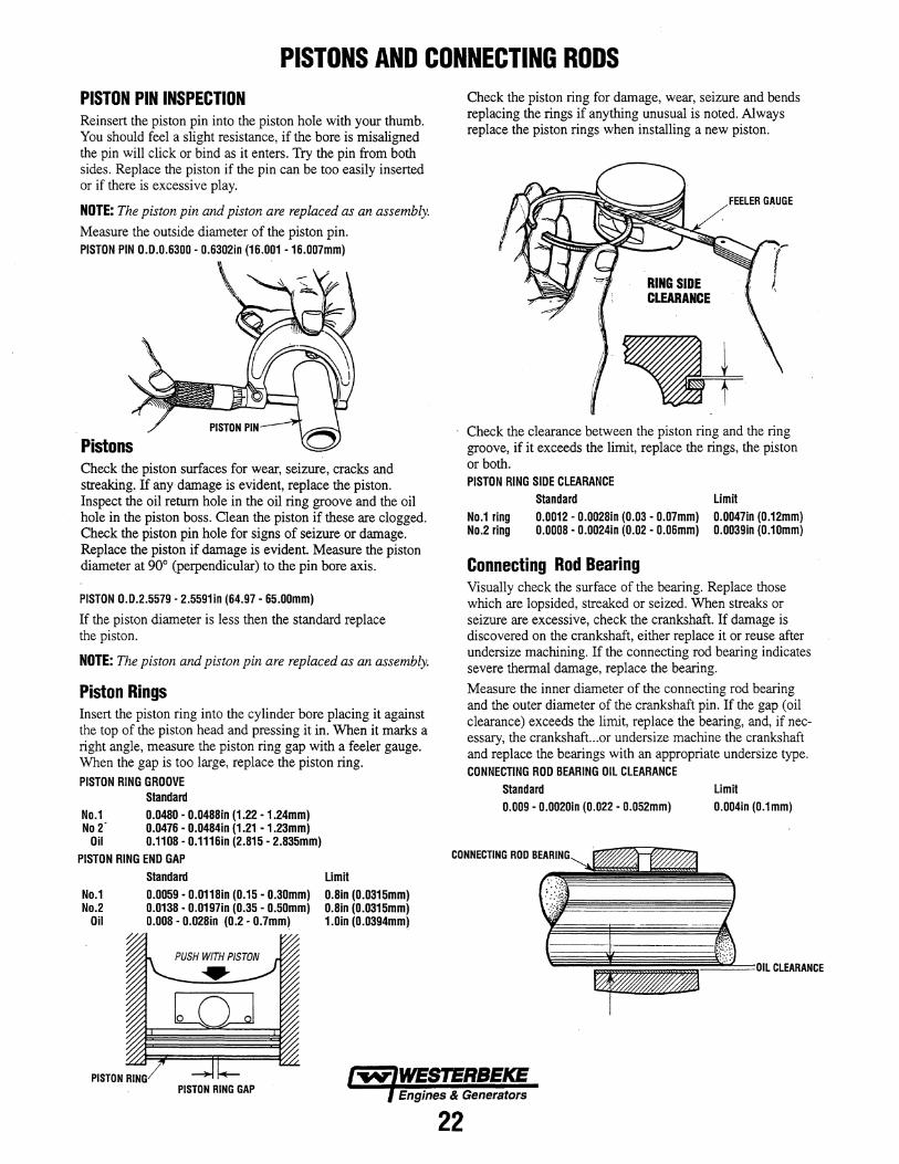
PISTONS AND CONNECTING RODS PISTON PIN INSPECTION Reinsert the piston pin into the piston hole with your thumb. You should feel a slight resistance, if the bore is misaligned the pin will click or bind as it enters. Try the pin from both sides. Replace the piston if the pin can be too easily inserted or if there is excessive play.
NOTE: The piston pin and piston are replaced as an assembly.
Measure the outside diameter of the piston pin. PISTON PIN 0.0.0.6300 - 0.6302in (16.001 -16.007mm)
Pistons Check the piston surfaces for wear, seizure, cracks and streaking. If any damage is evident, replace the piston. Inspect the oil return hole in the oil ring groove and the oil hole in the piston boss. Clean the piston if these are clogged. Check the piston pin hole for signs of seizure or damage. Replace the piston if damage is evident. Measure the piston diameter at 90° (perpendicular) to the pin bore axis.
PISTON 0.0.2.5579 - 2.5591in (64.97 - 65.00mm)
If the piston diameter is less then the standard replace the piston.
NOTE: The piston and piston pin are replaced as an assembly.
Piston Rings Insert the piston ring into the cylinder bore placing it against the top of the piston head and pressing it in. When it marks a right angle, measure the piston ring gap with a feeler gauge. When the gap is too large, replace the piston ring.
PISTON RING GROOVE Standard
No.1 0.0480 - 0.0488in (1.22 - 1.24mm) No 2' 0.0476 - 0.0484in (1.21 -1.23mm)
Oil 0.1108 - 0.1116in (2.815 - 2.835mm)
PISTON RING END GAP
No.1 No.2
Oil
%
Standard
0.0059 - 0.0118in (0.15 - 0.30mm) 0.0138 - 0.0197in (0.35 - 0.50mm) 0.008 - 0.028in (0.2 - 0.7mm)
Limit
0.8in (0.0315mm) 0.8in (0.0315mm) 1.Din (0.0394mm)
Check the piston ring for damage, wear, seizure and bends replacing the rings if anything unusual is noted. Always replace the piston rings when installing a new piston.
RING SIDE CLEARANCE
FEELER GAUGE
Check the clearance between the piston ring and the ring groove, if it exceeds the limit, replace the rings, the piston or both. PISTON RING SIDE CLEARANCE
Standard Limit
No.1 ring No.2 ring
0.0012 - 0.0028in (0.03 - 0.07mm) 0.0047in (0.12mm) 0.0008 - 0.0024in (0.02 - 0.06mm) 0.0039in (0.10mm)
Connecting Rod Bearing Visually check the surface of the bearing. Replace those which are lopsided, streaked or seized. When streaks or seizure are excessive, check the crankshaft. If damage is discovered on the crankshaft, either replace it or reuse after undersize machining. If the connecting rod bearing indicates severe thermal damage, replace the bearing.
Measure the inner diameter of the connecting rod bearing and the outer diameter of the crankshaft pin. If the gap (oil clearance) exceeds the limit, replace the bearing, and, if necessary, the crankshaft...or undersize machine the crankshaft and replace the bearings with an appropriate undersize type. CONNECTING ROD BEARING OIL CLEARANCE
Standard Limit
0.009 - 0.002Din (0.022 - 0.052mm) 0.004in (0.1mm)
CONNECTING ROD
~~~!~~~~~~~4=OILCLEARANCE
PISTON RING GAP Engines & Generators
22
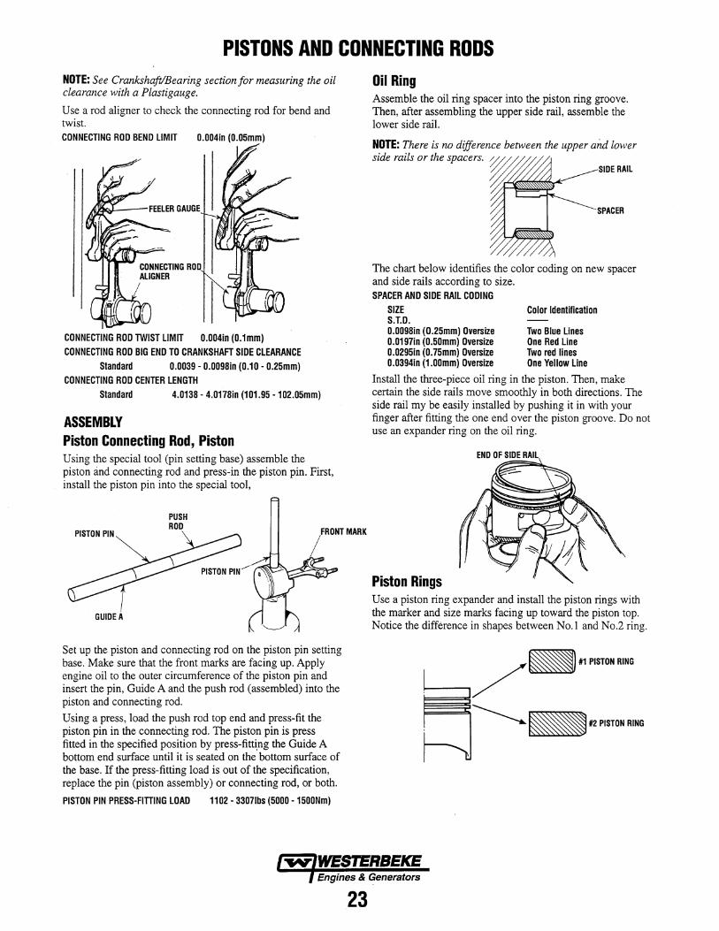
PISTONS AND CONNECTING RODS NOTE: See Crankshaft/Bearing section for measuring the oil clearance with a Plastigauge.
Use a rod aligner to check the connecting rod for bend and twist. CONNECTING ROD BEND LIMIT 0.004in (o.05mm)
CONNECTING ROD TWIST LIMIT 0.004in (o.1mm) CONNECTING ROD BIG END TO CRANKSHAFT SIDE CLEARANCE
Standard 0.0039 - 0.0098in (0.10 - 0.25mm) CONNECTING ROD CENTER LENGTH
Standard 4.0138 - 4.o178in (101.95 -102.o5mm)
ASSEMBLY Piston Connecting Rod, Piston Using the special tool (pin setting base) assemble the piston and connecting rod and press-in the piston pin. First, install the piston pin into the special tool,
PUSH ROD
GUIDE A
Set up the piston and connecting rod on the piston pin setting base. Make sure that the front marks are facing up. Apply engine oil to the outer circumference of the piston pin and insert the pin, Guide A and the push rod (assembled) into the piston and connecting rod.
Using a press, load the push rod top end and press-fit the piston pin in the connecting rod. The piston pin is press fitted in the specified position by press-fitti:ng the Guide A bottom end surface until it is seated on the bottom surface of the base. If the press-fitting load is out of the specification, replace the pin (piston assembly) or connecting rod, or both.
PISTON PIN PRESS-FITTING LOAD 1102 - 33071bs (5000 -15ooNm)
Oil Ring Assemble the oil ring spacer into the piston ring groove. Then, after assembling the upper side rail, assemble the lower side rail.
NOTE: There is no difference between the upper and lo·wer side rails or the spacers. j/'~~ /~ m SIDE RAIL
~~c-
'----"""'~ SPACER
The chart below identifies the color coding on new spacer and side rails according to size. SPACER AND SIDE RAIL CODING
SIZE Color Identification S.T.D. 0.0098in (O.25mm) Oversize Two Blue Lines 0.0197in (o.50mm) OverSize One Red Line 0.0295in (o.75mm) Oversize Two red lines 0.0394in (1.oomm) Oversize One Yellow Line
Install the three-piece oil ring in the piston. Then, make certain the side rails move smoothly in both directions. The side rail my be easily installed by pushing it in with your finger after fitting the one end over the piston groove. Do not use an expander ring on the oil ring.
END OF SIDE RAIL
Piston Rings Use a piston ring expander and install the piston rings with the marker and size marks facing up toward the piston top. Notice the difference in shapes between No.1 and No.2 ring.
~ __ -,/_""'TD.RI.' ~~1I2PISTONRING
Engines & Generators
23
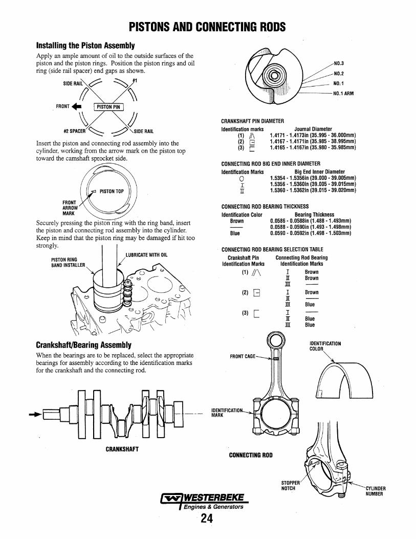
PISTONS AND CONNECTING RODS Installing the Piston Assembly Apply an ample amount of oil to the outside surfaces of the piston and the piston rings. Position the piston rings and oil ring (side rail spacer) end gaps as shown.
SIDERAIL ~
/I . FRONT +
~ !J It2 SPACER ~ -:::;:::? '\SIDE RAIL
Insert the piston and connecting rod assembly into the cylinder, working from the arrow mark on the piston top toward the camshaft sp(ocket side.
FRONT ARROW MARK
Securely pressing the piston ring with the ring band, insert the piston and connecting rod assembly into the cylinder. Keep in mind that the piston ring may be damaged if hit too strongly.
PISTON RING BANO INSTALLER /
LUBRICATE WITH OIL
Crankshaft/Bearing Assembly When the bearings are to be replaced, select the appropriate bearings for assembly according to the identification marks for the crankshaft and the connecting rod.
CRANKSHAFT
NO.3
NO.2
NO:1
F-----NO.1 ARM
CRANKSHAFT PIN DIAMETER Identification marks
(1) 11\ (2) G (3) C
Journal Diameter 1.4171 - 1.4173in (35.995 - 36.000mm) 1.4167 -1.4171in (35.985 - 38.995mm) 1.4165 -1.4167in (35.980 - 35.985mm)
CONNECTING ROD BIG END INNER DIAMETER Identification Marks
o I IT
Big End Inner Diameter 1.5354 - 1.5356in (39.000 - 39.005mm) 1.5356 - 1.5360in (39.005 - 39.015mm) 1.5360 - 1.5362in (39.015 - 39.020mm)
CONNECTING ROD BEARING THICKNESS
Identification Color Brown
Blue
Bearing Thickness 0.0586 - 0.0588in (1.488 - 1.493mm) 0.0588 - 0.0590in (1.493 -1.498mm) 0.0590 - 0.0592in (1.498 -1.503mm)
CONNECTING ROD BEARING SELECTION TABLE
Crankshaft Pin Identification Marks
(1) 1/\
(2) G
(3) [
Connecting Rod Bearing Identification Marks
I Brown n Brown ill I Brown n m Blue
I ][ Blue m Blue
0 IDENTIFICATION COLOR
IDENTIFICATION MARK
CONNECTING ROD
STOPPER NOTCH
Engines & Generators
24
CYLINDER NUMBER
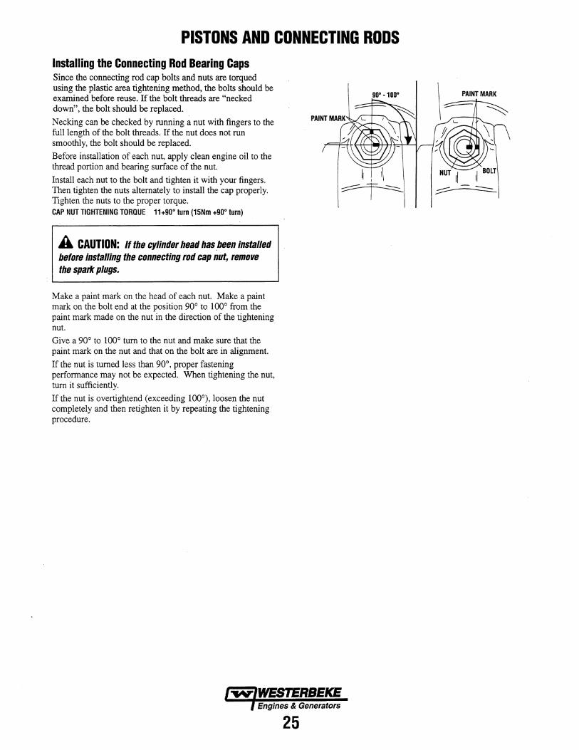
PISTONS AND CONNECTING RODS Installing the Connecting Rod Bearing Caps Since the connecting rod cap bolts and nuts are torqued using the plastic area tightening method, the bolts should be examined before reuse. If the bolt threads are "necked down", the bolt should be replaced.
Necking can be checked by running a nut with fingers to the full length of the bolt threads. If the nut does not run smoothly, the bolt should be replaced.
Before installation of each nut, apply clean engine oil to the thread portion and bearing surface of the nut.
Install each nut to the bolt and tighten it with your fingers. Then tighten the nuts alternately to install the cap properly. Tighten the nuts to the proper torque. CAP NUT TIGHTENING TORQUE 11+90· turn (15Nm +90· turn)
A CAUTION: If the cylinder head has ,been installed before installing the connecting rod cap nut, remove the spark plugs.
Make a paint mark on the head of each nut. Make a paint mark on the bolt end at the position 90° to 100° from the paint mark made on the nut in the direction of the tightening nut.
Give a 90° to 100° tum to the nut and make sure that the paint mark on the nut and that on the bolt are in alignment.
If the nut is turned less than 90°, proper fastening performance may not be expected. When tightening the nut, tum it sufficiently.
If the nut is overtightend (exceeding 100°), loosen the nut completely and then retighten it by repeating the tightening procedure.
Engines & Generators
25
FRONT CASE I COUNTERBALANCE SHAFT AND OIL PAN
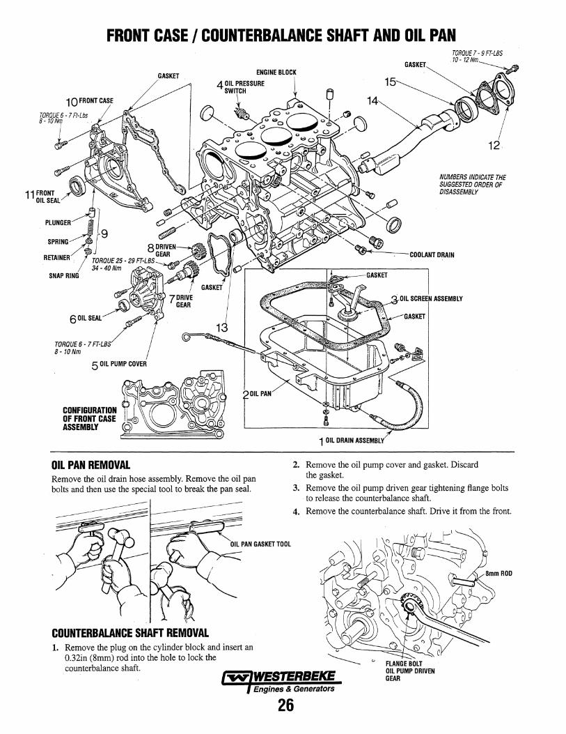
TORQUE 6 -1 Ft-Lbs '-1
5 OIL PUMP COVER
CONFIGURATION OF FRONT CASE ASSEMBLY
OIL PAN REMOVAL
GASKET
Remove the oil drain hose assembly. Remove the oil pan bolts and then use the special tool to break the pan seal. ----
COUNTERBALANCE SHAFT REMOVAL 1. Remove the plug on the cylinder block and insert an
0.32in (8mm) rod into the hole to lock the counterbalance shaft.
GASKET
NUMBERS INDICATE THE SUGGESTED ORDER OF DISASSEMBLY
COOLANT DRAIN
. OIL SCREEN ASSEMBLY 1J"fQ.~L--"'"
1 OIL DRAIN ASSEMBLY
2. Remove the oil pump cover and gasket. Discard the gasket.
3. Remove the oil pump driven gear tightening flange bolts to release the counterbalance shaft.
4. Remove the counterbalance shaft. Drive it from the front.
FLANGE BOLT OIL PUMP DRIVEN GEAR
Engines & Generators
26
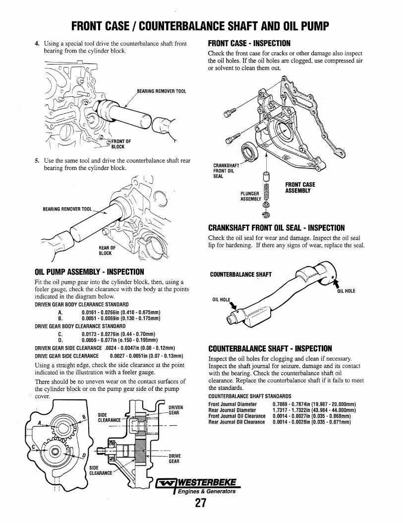
FRONT CASE I COUNTERBALANCE SHAFT AND OIL PUMP 4. Using a special tool drive the counterbalance shaft front
bearing from the cylinder block.
EARING REMOVER TOOL
5. Use the same tool and drive the counterbalance shaft rear bearing from the cylinder block.
OIL PUMP ASSEMBLY· INSPECTION Fit the oil pump gear into the cylinder block, then, using a feeler gauge, check the clearance with the body at the points indicated in the diagram below. DRIVEN GEAR BODY CLEARANCE STANDARD
A. 0.0161 - 0.0266in (0.410 - 0.675mm) B. 0.0051 • 0.0069in (0.130 - 0.175mm)
DRIVE GEAR BODY CLEARANCE STANDARD C. 0.0173 - 0.0276in (0.44 - 0.7omm) D. 0.0059 - 0.077in (0.150 - 0.195mm)
DRIVEN GEAR SIDE CLEARANCE .0024· 0.0047in (0.06 - 0.12mm) DRIVE GEAR SIDE CLEARANCE 0.0027 - 0.0051in (0.07 - 0.13mm)
Using a straight edge, check the side clearance at the point indicated in the illustration with a feeler gauge.
There should be no uneven wear on the contact surfaces of the cylinder block or on the pump gear side of the pump
-C+---DRIVE GEAR
FRONT CASE· INSPECTION Check the front case for cracks or other damage also inspect the oil holes. If the oil holes are clogged, use compressed air or solvent to clean them out.
CRANKSHAFT FRONT OIL SEAL
CRANKSHAFT FRONT OIL SEAL· INSPECTION Check the oil seal for wear and damage. Inspect the oil seal lip for hardening. If there any signs of wear, replace the seal.
COUNTERBALANCE SHAFT
COUNTERBALANCE SHAFT· INSPECTION Inspect the oil holes for clogging and clean if necessary. Inspect the shaft journal for seizure, damage and its contact with the bearing. Check the counterbalance shaft oil clearance. Replace the counterbalance shaft if it fails to meet the standards. COUNTERBALANCE SHAFT STANDARDS Front Journal Diameter Rear Journal Diameter Front Journal Oil Clearance Rear Journal Oil Clearance
0.7869 - 0.7874in (19.987 - 2o.ooomm) 1.7317 -1.7322in (43.984 - 44.ooomm) 0.0014 - 0.0027in (0.035 - 0.068mm) 0.0014 - 0.0028in (0.035' 0.071mm)
Engines & Generators
27
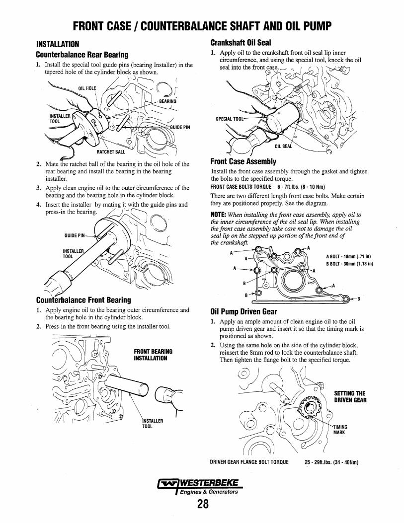
FRONT CASE I COUNTERBALANCE SHAFT AND OIL PUMP INSTALLATION Counterbalance Rear Bearing
. 1. Install the special tool guide pins (bearing Installer) in the tapered hole of the cylinder block as shown.
,j ( ) r----.. ( \ ~~J Gr ~\ BEARING-
2. Mate the ratchet ball of the bearing in the oil hole of the rear bearing and install the bearing in the bearing installer.
3. Apply clean engine oil to the outer Circumference of the bearing and the bearing hole in the cylinder block.
4.
GUIDE PIN -""".v
\
Counterbalance Front Bearing 1. Apply engine oil to the bearing outer circumference and
the bearing hole in the cylinder block.
2. Press-in the front bearing using the installer tool.
FRONT BEARING INSTALLATION
Crankshaft Oil Seal 1. Apply oil to the crankshaft front oil sea1lip inner
circumference, and using the special tool, knock the oil
~mro~_t=,.~ ~ pi
Front Case Assembly Install the front case assembly through the gasket and tighten the bolts to the specified torque. FRONT CASE BOLTS TORQUE 6 - 7ft.lbs. (8 -10 Nm)
There are two different length front case bolts. Make certain they are positioned properly. See the diagram.
NOTE: When installing the front case assembly, apply oil to the inner circumference of the oil seal lip. When installing the front case assembly take care not to damage the oil seal lip on the stepped up portion of the front end of the crankshaft.
A A
B
Oil Pump Driven Gear
A BOLT -18mm (.71 in)
B BOLT· 30mm (1.18 in)
B
1. Apply an ample amount of clean engine oil to the oil pump driven gear and insert it so that the timing mark is positioned as shown.
2. Using the same hole on the side of the cylinder block, reinsert the 8mm rod to lock the counterbalance shaft. Then tighten the flange bolt to the specified torque.
~ ;; ~'-----"""'\\""\ rJ6 >b ~ ~VJ\ OJ
~~
SETTING THE DRIVEN GEAR
TIMING MARK
ORIVEN GEAR FLANGE BOLT TORQUE 25 - 29ft.lbs. (34 • 40Nm)
Engines & Generators
28
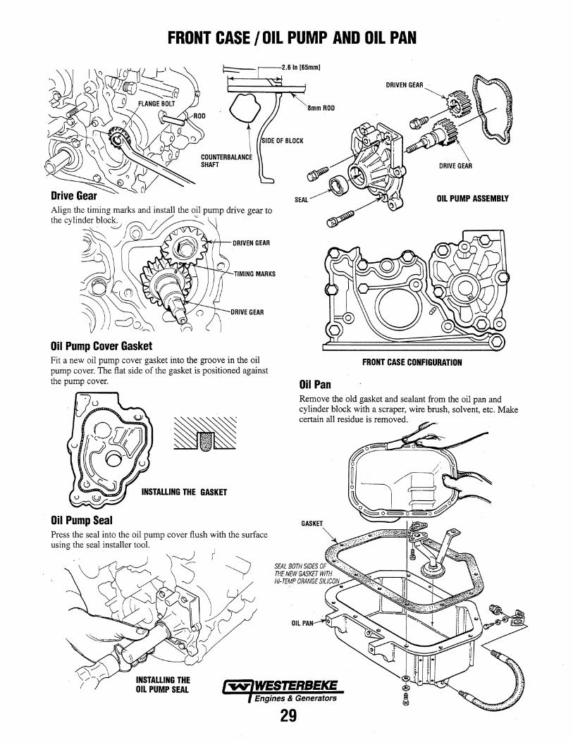
FRONT CASE lOlL PUMP AND OIL PAN
TIMING MARKS
Oil Pump Cover Gasket Fit a new oil pump cover gasket into the groove in the oil pump cover. The flat side of the gasket is positioned against the pump cover.
Oil Pump Seal Press the seal into the oil pump cover flush with the surface using the seal installer tool.
INSTALLING THE OIL PUMP SEAL
2.6 In [65mm[
'8mm ROD
OIL PUMP ASSEMBLY
FRONT CASE CONFIGURATION
Oil Pan Remove the old gasket and sealant from the oil pan and cylinder block with a scraper, wire brush, solvent, etc. Make certain all residue is removed.
GASKET
OIL PAN·
Engines & Generators
29
CRANKSHAFT I BEARINGS AND OIL SEAL
NUMBERS INDICATE THE SUGGESTED ORDER OF DISASSEMBLY
CYLINDER BLOCK
8 CRANKSHAFT BEARING (UPPER)
INSPECT THE JOURNALS _ FOR UNEVEN WEAR. CHECK FOR CRACKS. BENDS. AND CLOGGED OIL HOLES.
9 CRANKSHAFT
TORQUE 98 - 105 FT-LBS-_d~. ,@) [135 - 145 Nm]
MAIN BEARING BOLT TORQUE 36 - 40 FT-LBS [50-56Nm]
1 OIL SEAL CASE BOLT ! TORQUE 1- 9 Ft-Lbs 1'0-'2Nm
THRUST BEARING
~ ____ -----q- BEARING CAP BOLT
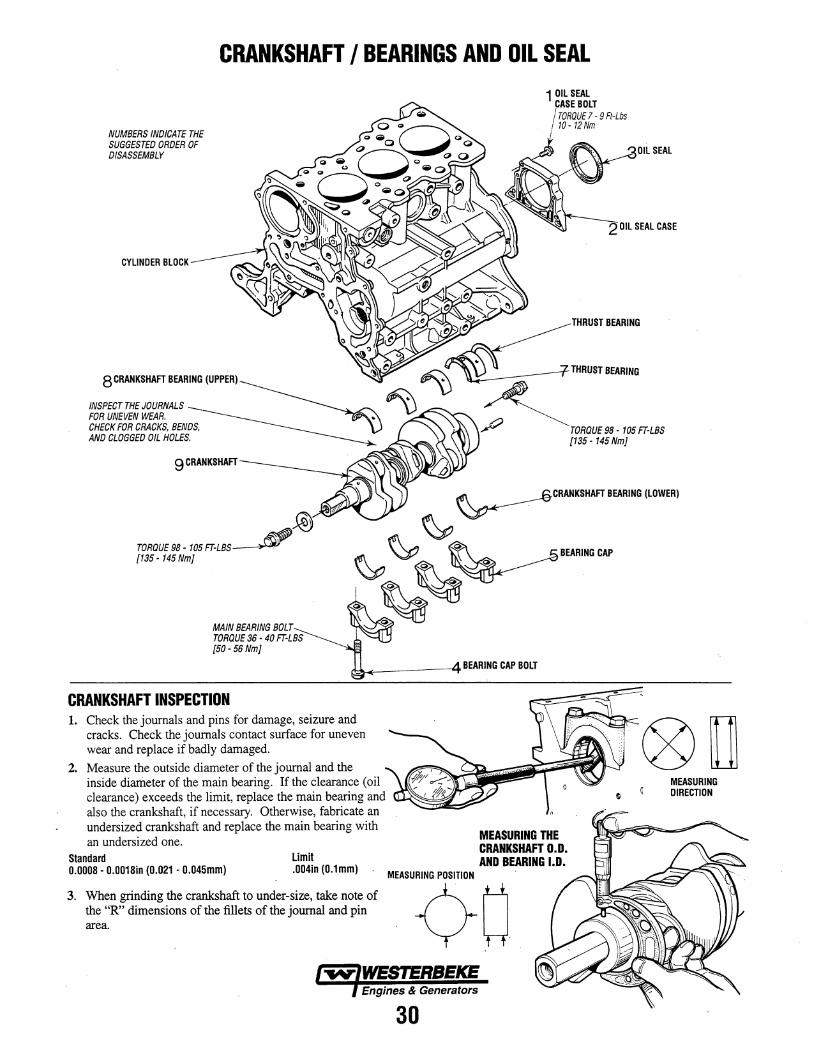
CRANKSHAFT INSPECTION 1. Check the journals and pins for damage, seizure and
cracks. Check the journals contact surface for uneven wear and replace if badly damaged.
2. Measure the outside diameter of the journal and the inside diameter of the main bearing. If the clearance (oil clearance) exceeds the limit, replace the main bearing and also the crankshaft, if necessary. Otherwise, fabricate an undersized crankshaft and replace the main bearing with an undersized one.
Standard Limit 0.0008 - 0.0018in (0.021 - 0.045mm) .004in (0.1mm)
3. When grinding the crankshaft to under-size, take note of the "R" dimensions of the fillets of the journal and pin area.
MEASURING POSITION
MEASURING THE CRANKSHAFT 0.0. AND BEARING 1.0.
¢-w Engines & Generators
30
MEASURING DIRECTION
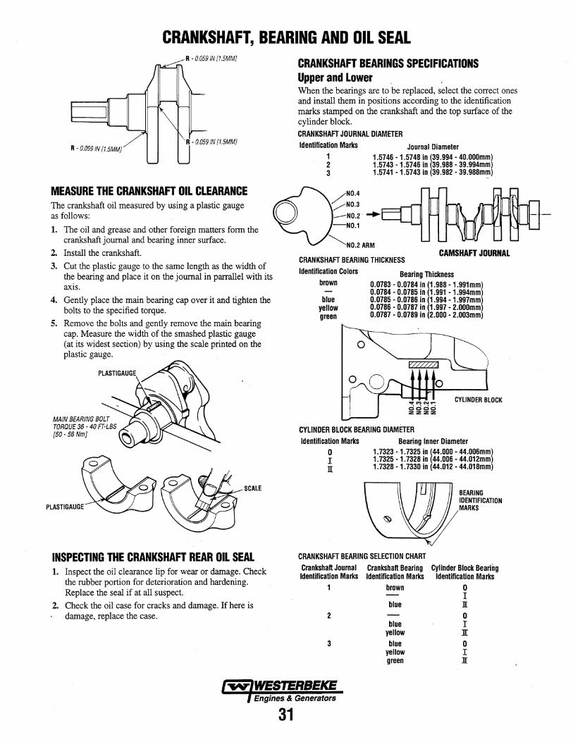
CRANKSHAFT, BEARING AND OIL SEAL R - 0.059 IN {1.5MMJ
R - 0.059 IN (1.5MMJ
MEASURE THE CRANKSHAFT OIL CLEARANCE The crankshaft oil measured by using a plastic gauge as follows:
1. The oil and grease and other foreign matters form the crankshaft journal and bearing inner surface.
2. InstaII the crankshaft.
3. Cut the plastic gauge to the same length as the width of the bearing and place it on the journal in parrallel with its axis.
4. Gently place the main bearing cap over it and tighten the bolts to the specified torque.
5. Remove the bolts and gently remove the main bearing cap. Measure the width of the smashed plastic gauge (at its widest section) by using the scale printed on the plastic gauge.
MAIN BEARING BOLT TORQUE 36 - 40 FT-LBS [SO-S6NmJ
PLASTIGAUGE
II!.....-'_~ SCALE
INSPECTING THE CRANKSHAFT REAR OIL SEAL 1. Inspect the oil clearance lip for wear or damage. Check
the rubber portion for deterioration and hardening. Replace the seal if at all suspect.
2. Check the oil case for cracks and damage. If here is damage, replace the case.
CRANKSHAFT BEARINGS SPECIFICATIONS Upper and Lower When the bearings are to be replaced, select the correct ones and install them in positions according to the identification marks stamped on the crankshaft and the top surface of the cylinder block. CRANKSHAFT JOURNAL DIAMETER Identification Marks
1 2 3
Journal Diameter 1.5746 -1.5748 in 139.994 - 40.000mm) 1.5743 -1.5746 in 39.988 - 39.994mm) 1.5741 -1.5743 in 39.982 - 39.988mm)
CAMSHAFT JOURNAL CRANKSHAFT BEARING THICKNESS Identification Colors
brown
blue yellow green
Bearing Thickness 0.0783 - 0.0784 in (1.988 - 1.991mm) 0.0784 - 0.0785 in 1.991 - 1.994mm 0.0785 - 0.0786 in 1.994 -1.997mm 0.0786 - 0.0787 in 1.997 - 2.000mm 0.0787 - 0.0789 in 2.000 - 2.003mm
.. MN ...... CYLINDER BLOCK 0000 :z :z :z:z
CYLINDER BLOCK BEARING DIAMETER Identification Marks
o I n
Bearing Inner Diameter 1.7323 -1.7325 in 144.000 - 44.006mm} 1.7325 -1.7328 in 44.006 - 44.012mm 1.7328 -1.7330 in 44.012 - 44.018mm
BEARING IDENTIFICATION MARKS
CRANKSHAFT BEARING SELECTION CHART Crankshaft Journal Crankshaft Bearing Cylinder Block Bearing Identification Marks Identification Marks Identification Marks
1 brown 0 I
blue ][
2 0 blue I
yellow ][
3 blue 0 yellow I green ][
Engines & Generators
31
CRANKSHAFTI BEARING AND OIL SEAL
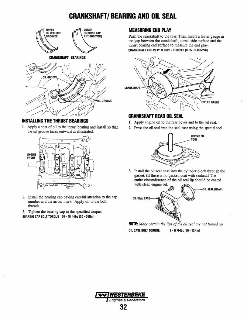
CRANKSHAFT BEARINGS
INSTALLING THE THRUST BEARINGS 1. Apply a coat of oil to the thrust beating and install so that
the oil groove faces outward as illustrated.
2. Install the bearing cap paying careful attention to the cap number and the arrow mark. Apply oil to the bolt threads.
3. Tighten the bearing cap to the specified torque. BEARING CAP BOLT TORQUE 36 - 40 ft-Ibs (50 - 55Nm)
MEASURING END PLAY Push the crankshaft to the rear. Then, insert a feeler gauge in the gap between the crankshaftjoumal side surface and the thrust bearing end surface to measure the end play. CRANKSHAFT END PLAY: 0.0020 - O.OOOgin (0.05 - 0.025mm)
CRANKSHAFT
CRANKSHAFT REAR OIL SEAL 1. Apply engine oil to the rear cover and to the oil seal.
2. Press the oil seal into the seal case using the special tool.
3.
OIL SEAL CASE--""
NOTE: Make certain the lips of the oil seal are not turned up.
OIL CASE BOLT TORQUE: 7 - g Ft-Ibs (10 -12Nm)
Engines & Generators
32
CYLINDER BLOCK INSPECTION AND PISTON CLEARANCE
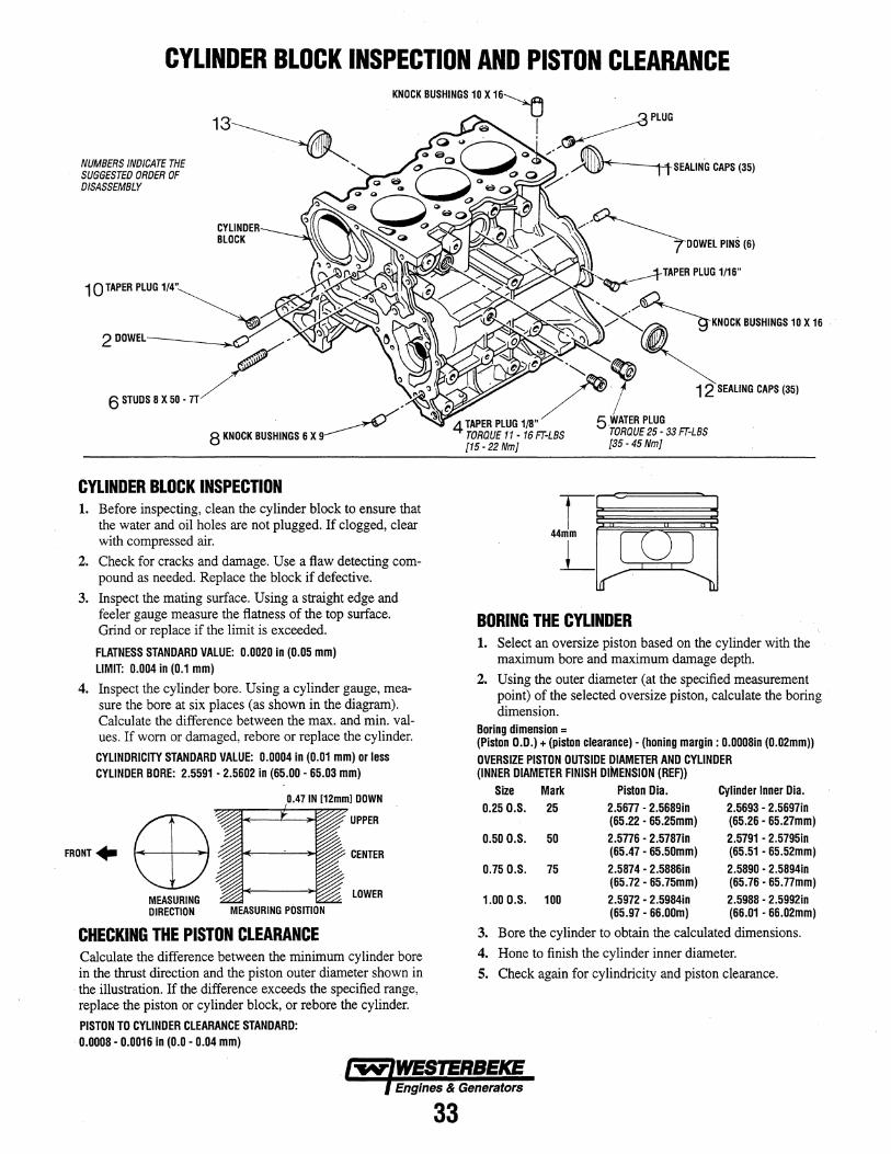
NUMBERS INDICATE THE SUGGESTED ORDER OF DISASSEMBLY
10 TAP"' PlUG 1/'.~
2 DOWEL- ~-
6STUDS8X5 •. 7T/ .
8 KNOCK BUSHINGS 6 X 9~
CYLINDER BLOCK INSPECTION 1. Before inspecting, clean the cylinder block to ensure that
the water and oil holes are not plugged. If clogged, clear with compressed air.
2. Check for cracks and damage. Use a flaw detecting compound as needed. Replace the block if defective.
3. Inspect the mating surface. Using a straight edge and feeler gauge measure the flatness of the top surface. Grind or replace if the limit is exceeded.
FLATNESS STANDARD VALUE: 0.0020 in (0.05 mm) LIMIT: 0.004 in (0.1 mm)
4. Inspect the cylinder bore. Using a cylinder gauge, measure the bore at six places (as shown in the diagram). Calculate the difference between the max. and min. values. If worn or damaged, rebore or replace the cylinder.
CYLINDRICITY STANDARD VALUE: 0.0004 in (0.01 mm) or less CYLINDER BDRE: 2.5591 - 2.5602 in (65.00 - 65.03 mm)
UPPER
CENTER
MEASURING DIRECTION MEASURING POSITION
LOWER
CHECKING THE PISTON CLEARANCE Calculate the difference between the minimum cylinder bore in the thrust direction and the piston outer diameter shown in
. the illustration. If the difference exceeds the specified range, replace the piston or cylinder block, or rebore the cylinder.
PISTON TO CYLINDER CLEARANCE STANDARD: 0.0008 - 0.0016 in (0.0 - 0.04 mm)
ltSEALING CAPS (35)
BORING THE CYLINDER 1. Select an oversize piston based on the cylinder with the
maximum bore and maximum damage depth.
2. Using the outer diameter (at the specified measurement point) of the selected oversize piston, calculate the boring dimension.
Boring dimension = (Piston O.D.) + (piston clearance) - (honing margin: 0.0008in (0.02mm)) OVERSIZE PISTON OUTSIDE DIAMETER AND CYLINDER (INNER DIAMETER FINISH DIMENSION (REF))
Size Mark Piston Dia. Cylinder Inner Dia. 0.250.S. 25 2.5677 - 2.5689in 2.5693 - 2.5697in
(65.22 - 65.25mm) (65.26 - 65.27mm) 0.500.S. 50 2.5776 - 2.5787in 2.5791 - 2.5795in
(65.47 - 65.50mm) (65.51 - 65.52mm) 0.750.S. 75 2.5874 - 2.5886in 2.5890 - 2.5894in
(65.72 - 65.75mm) (65.76 - 65.77mm) 1.000.S. 100 2.5972 - 2.5984in 2.5988 - 2.5992in
(65.97 - 66.00m) (66.01 - 66.02mm)
3. Bore the cylinder to obtain the calculated dimensions.
4. Hone to finish the cylinder inner diameter.
S. Check again for cylindricity and piston clearance .
Engines & Generators
33
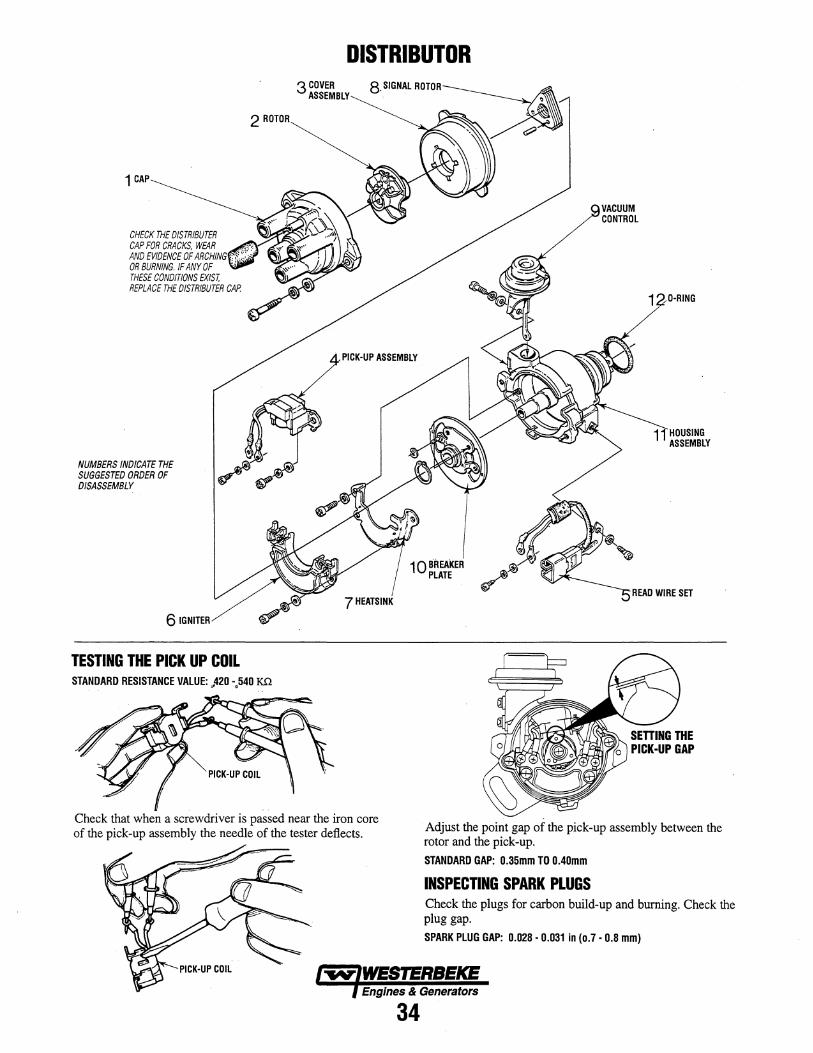
1 CAP
CHECK THE DISTRIBUTER CAP FOR CRACKS, WEAR AND EVIDENCE OF ARCHING OR BURNING. IF ANY OF THESE CONDITIONS EXIST, REPLACE THE DISTRIBUTER CAP.
NUMBERS INDICATE THE SUGGESTED ORDER OF DISASSEMBLY
6 IGNITER
2 ROTOR
TESTING THE PICK UP COIL STANDARD RESISTANCE VALUE: ,,420 -.540 KQ
DISTRIBUTOR 3 COVER
ASSEMBLY
PICK-UP ASSEMBLY
10 BREA'KER PLATE
VACUUM CONTROL
1 O-RING
HOUSING ASSEMBLY
REAO WIRE SET
Check that when a screwdriver is passed near the iron core of the pick-up assembly the needle of the tester deflects. Adjust the point gap of the pick-up assembly between the
rotor and the pick-up,
STANDARD GAP: 0.35mm TO 0.40mm
INSPECTING SPARK PLUGS Check the plugs for carbon build-up and burning. Check the plug gap.
SPARK PLUG GAP: 0.028 - 0.031 in (0.7 - 0.8 mm)
Engines & Generators
34
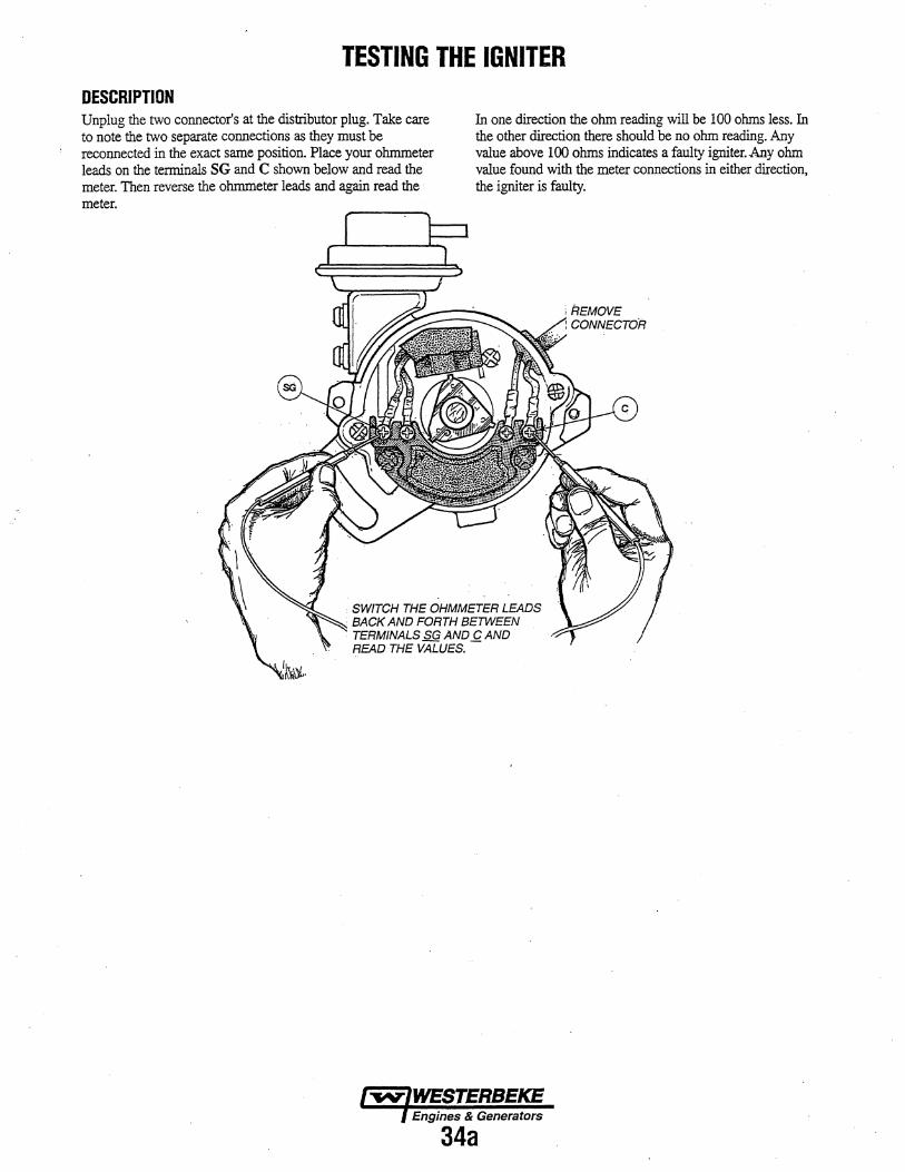
TESTING THE IGNITER DESCRIPTION Unplug the two connector's at the distributor plug. Take care to note the two separate connections as they must be reconnected in the exact same position. Place your ohmmeter leads on the tenninals SG and C shown below and read the meter. Then reverse the ohmmeter leads and again read the
In one direction the ohm reading will be 100 ohms less. In the other direction there should be no ohm reading. Any value above 100 ohms indicates a faulty igniter. Any ohm value found with the meter connections in either direction, the igniter is faulty.
meter.
. SWITCH THE OHMMETER LEADS
. BACK AND FORTH BETWEEN TERMINALS SG AND l! AND READ THE VALUES.
Engines & Generators
34a
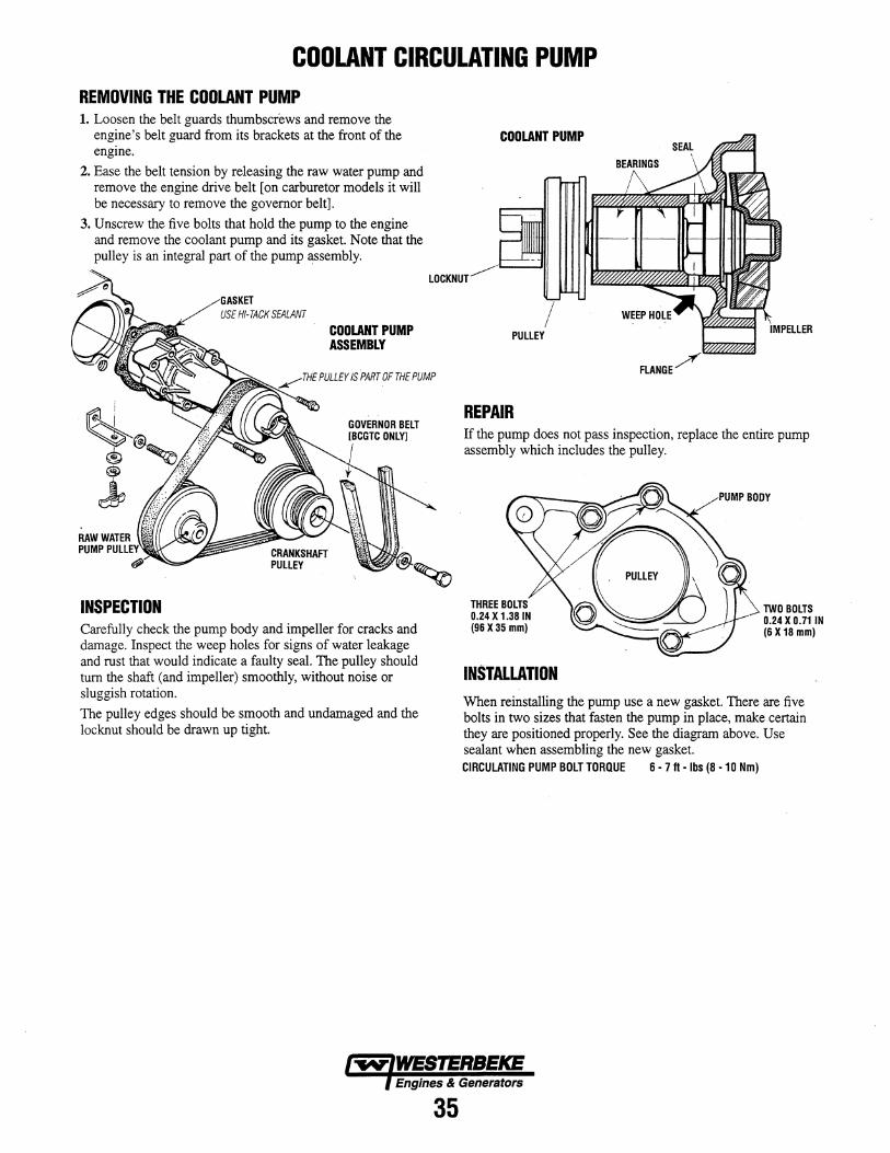
COOLANT CIRCULATING PUMP REMOVING THE COOLANT PUMP 1. Loosen the belt guards thumbscrews and remove the
engine's belt guard from its brackets at the front of the engine.
2. Ease the belt tension by releasing the raw water pump and remove the engine drive belt [on carburetor models it will be necessary to remove the governor belt].
3. Unscrew the five bolts that hold the pump to the engine and remove the coolant pump and its gasket. Note that the pulley is an integral part of the pump assembly.
~
INSPECTION
GASKET USE HI-TACK SEALANT
COOLANT PUMP ASSEMBLY
~THE PULLEY IS PART OF THE PUMP
Carefully check the pump body and impeller for cracks and damage. Inspect the weep holes for signs of water leakage and rust that would indicate a faulty seal. The pulley should tum the shaft (and impeller) smoothly, without noise or sluggish rotation.
The pulley edges should be smooth and undamaged and the locknut should be drawn up tight.
COOLANT PUMP
PULLEY
FLANGE
REPAIR If the pump does not pass inspection, replace the entire pump assembly which includes the pulley.
THREE BOLTS 0.24 X 1.38 IN (96X35 mm)
INSTALLATION
TWO BOLTS 0.24 X 0.71 IN (6X18 mm)
When reinstalling the pump use a new gasket. There are five bolts in two sizes that fasten the pump in place, make certain they are positioned properly. See the diagram above. Use sealant when assembling the new gasket. CIRCULATING PUMP BOLT TORQUE 6 • 7 It • Ibs (8 • 10 Nm)
Engines & Generators
35
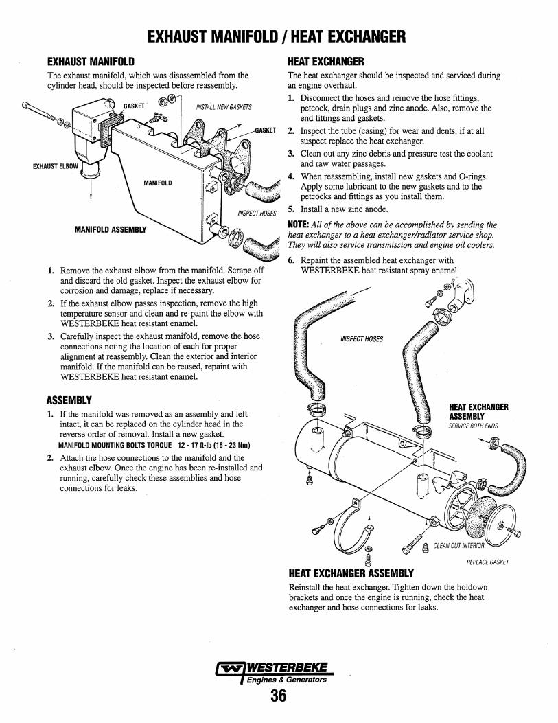
EXHAUST MANIFOLD I HEAT EXCHANGER EXHAUST MANIFOLD The exhaust manifold, which was disassembled from the cylinder head, should be inspected before reassembly.
INSTALL NEW GASKETS
MANIFOLD ASSEMBLY
1. Remove the exhaust elbow from the manifold. Scrape off and discard the old gasket. Inspect the exhaust elbow for corrosion and damage, replace if necessary.
2. If the exhaust elbow passes inspection, remove the high temperature sensor and clean and re-paint the elbow with WESTERBEKE heat resistant enamel.
3. Carefully inspect the exhaust manifold, remove the hose connections noting the location of each for proper alignment at reassembly. Clean the exterior and interior manifold. If the manifold can be reused, repaint with WESTERBEKE heat resistant enamel.
ASSEMBLY 1. If the manifold was removed as an assembly and left
intact, it can be replaced on the cylinder head in the reverse order of removal. Install a new gasket. MANIFOLD MOUNTING BOLTS TORQUE 12 -17 ft-Ib (16 - 23 Nm)
2. Attach the hose connections to the manifold and the exhaust elbow. Once the engine has been re-installed and running, carefully check these assemblies and hose connections for leaks.
HEAT EXCHANGER The heat exchanger should be inspected and serviced during an engine overhaul.
1. Disconnect the hoses and remove the hose fittings, petcock, drain plugs and zinc anode. Also, remove the end fittings and gaskets.
2. Inspect the tube (casing) for wear and dents, if at all suspect replace the heat exchanger.
3. Clean out any zinc debris and pressure test the coolant and raw water passages.
4. When reassembling, install new gaskets and O-rings. Apply some lubricant to the new gaskets and to the petcocks and fittings as you install them.
5. Install a new zinc anode.
NOTE: All of the above can be accomplished by sending the heat exchanger to a heat exchangerlradiator service shop. They will also service transmission and engine oil coolers.
6. Repaint the assembled heat exchanger with WESTERBEKE heat resistant spray enamel
INSPECT HOSES
~ HEAT EXCHANGER ASSEMBLY
~7"' '?\ ? ",~i
HEAT EXCHANGER ASSEMBLY SERVICE BOTH ENDS
REPLACE GASKET
Reinstall the heat exchanger. Tighten down the holdown brackets and once the engine is running, check the heat exchanger and hose connections for leaks.
Engines & Generators
36
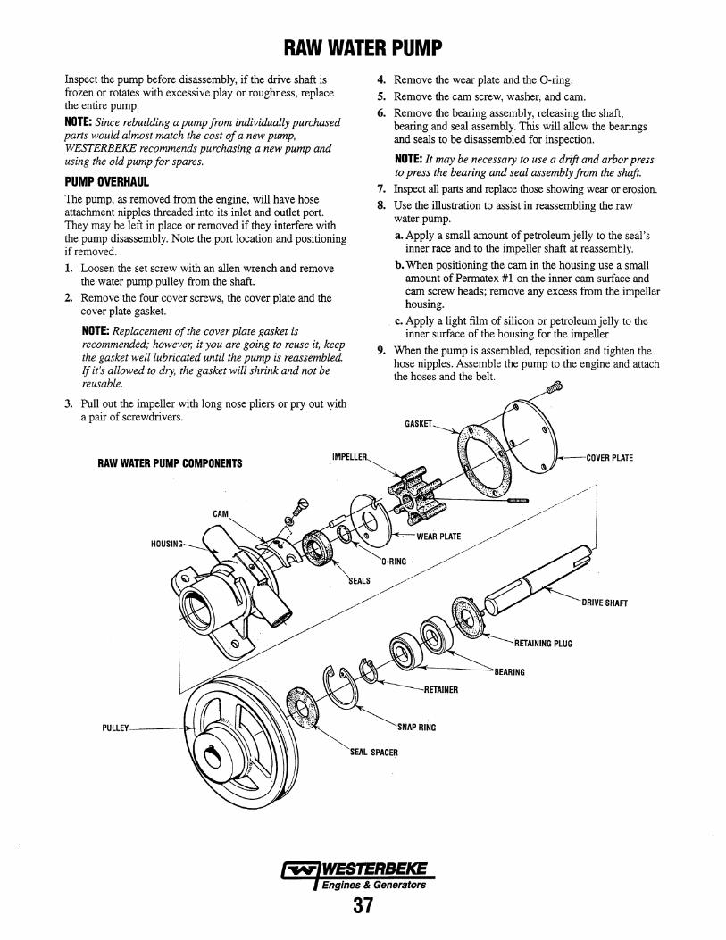
RAW WATER PUMP Inspect the pump before disassembly, if the drive shaft is frozen or rotates with excessive play or roughness, replace the entire pump.
NOTE: Since rebuilding a pump from individually purchased parts would almost match the cost of a new pump, WESTERBEKE recommends purchasing a new pump and using the old pump for spares.
PUMP OVERHAUL The pump, as removed from the engine, will have hose attachment nipples threaded into its inlet and outlet port. They may be left in place or removed if they interfere with the pump disassembly. Note the port location and positioning if removed.
1. Loosen the set screw with an allen wrench and remove the water pump pulley from the shaft.
2. Remove the four cover screws, the cover plate and the cover plate gasket.
NOTE: Replacement of the cover plate gasket is recommended; however, it you are going to reuse it, keep the gasket well lubricated until the pump is reassembled. If it's allowed to dry, the gasket will shrink and not be reusable.
3. Pull out the impeller with long nose pliers or pry out ..yith a pair of screwdrivers.
RAW WATER PUMP COMPONENTS
PULLEY---_~
4. Remove the wear plate and the O-ring.
5. Remove the cam screw, washer, and cam. 6. Remove the bearing assembly, releasing the shaft,
bearing and seal assembly. This will allow the bearings and seals to be disassembled for inspection.
NOTE: It may be necessary to use a drift and arbor press to press the bearing and seal assembly from the shaft.
7. Inspect all parts and replace those showing wear or erosion. 8. Use the illustration to assist in reassembling the raw
water pump.
a. Apply a small amount of petroleum jelly to the seal's inner race and to the impeller shaft at reassembly.
b. When positioning the cam in the housing use a small amount of Permatex #1 on the inner cam surface and cam screw heads; remove any excess from the impeller housing.
c. Apply a light film of silicon or petroleum jelly to the inner surface of the housing for the impeller
9. When the pump is assembled, reposition and tighten the hose nipples. Assemble the pump to the engine and attach the hoses and the belt.
1L.t ___ I'nVFR PLATE
SHAFT
"lll::l~---<RI:rAIIIING PLUG
~~oo(----::':::"'BEARING
SPACER
Engines & Generators
37
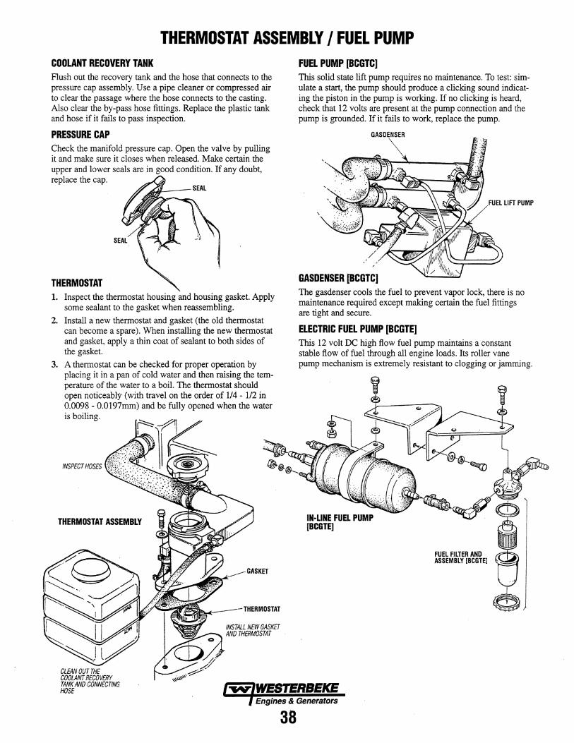
THERMOSTAT ASSEMBLY I FUEL PUMP COOLANT RECOVERY TANK Flush out the recovery tank and the hose that connects to the pressure cap assembly. Use a pipe cleaner or compressed air to clear the passage where the hose connects to the casting. Also clear the by-pass hose fittings. Replace the plastic tank and hose if it fails to pass inspection.
PRESSURE CAP Check the manifold pressure cap. Open the valve by pulling it and make sure it closes when released. Make certain the upper and lower seals are in good condition. If any doubt, replace the cap.
THERMOSTAT 1. Inspect the thermostat housing and housing gasket. Apply
some sealant to the gasket when reassembling.
2. Install a new thermostat and gasket (the old thermostat can become a spare). When installing the new thermostat and gasket, apply a thin coat of sealant to both sides of the gasket.
3. A thermostat can be checked for proper operation by placing it in a pan of cold water and then raising the temperature of the water to a boil. The thermostat should open noticeably (with travel on the order of 114 - 1/2 in 0.0098 - 0.0197mm) and be fully opened when the water is boiling.
THERMOSTAT ASSEMBLY
CLEAN OUT THE COOLANT RECOVERY TANK AND CONNECTING HOSE
THERMOSTAT
FUEL PUMP [BCGTC] This solid state lift pump requires no maintenance. To test: simulate a start, the pump should produce a clicking sound indicating the piston in the pump is working. If no clicking is heard, check that 12 volts are present at the pump connection and the pump is grounded. If it fails to work, replace the pump.
GASDENSER
GASDENSER [BCGTC] The gasdenser cools the fuel to prevent vapor lock, there is no maintenance required except making certain the fuel fittings are tight and secure.
ELECTRIC FUEL PUMP [BCGTE] This 12 volt DC high flow fuel pump maintains a constant stable flow of fuel through all engine loads. Its roller vane pump mechanism is extremely resistant to clogging or jamming.
IN·LlNE FUEL PUMP [BeGTE] ~i
FUEL FILTER AND ~ ASSEMBLY [BCGTE] U
e
Engines & Generators
38
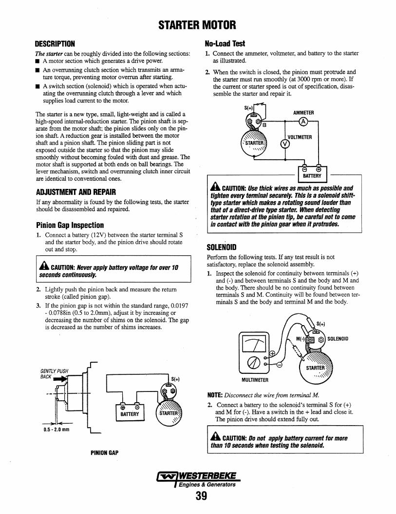
STARTER MOTOR DESCRIPTION The starter can be roughly divided into the following sections: • A motor section which generates a drive power.
• An overrunning clutch section which transmits an armature torque, preventing motor overrun after starting.
• A switch section (solenoid) which is operated when actuating the overrunning clutch through a lever and which supplies load current to the motor.
The starter is a new type. small. light-weight and is called a high-speed internal-reduction starter. The pinion shaft is separate from the motor shaft; the pinion slides only on the pinion shaft. A reduction gear is installed between the motor shaft and a pinion shaft. The pinion sliding part is not exposed outside the starter so that the pinion may slide smoothly without becoming fouled with dust and grease. The motor shaft is supported at both ends on ball bearings. The lever mechanism. switch and overrunning clutch inner circuit are identical to conventional ones.
ADJUSTMENT AND REPAIR If any abnormality is found by the following tests, the starter should be disassembled and repaired.
Pinion Gap Inspection 1. Connect a battery (l2V) between the starter terminal S
and the starter body, and the pinion drive should rotate out and stop.
A CAUTION: Never apply battery voltage for over 10 seconds continuously.
2. Lightly push the pinion back and measure the return stroke (called pinion gap).
3. If the pinion gap is not within the standard range, 0.0197 - 0.0788in (0.5 to 2.0mm), adjust it by increasing or decreasing the number of shims on the solenoid. The gap is decreased as the number of shims increases.
0.5-2.0 mm
PINION GAP
No-Load Test 1. Connect the ammeter, voltmeter. and battery to the starter
as illustrated.
2. When the switch is closed, the pinion must protrude and the starter must run smoothly (at 3000 rpm or more). If the current or starter speed is out of specification, disassemble the starter and repair it.
BAmRY
A CAUTION: Use thick wires as much as possible and tighten every tenninal securely. This is a solenoid shifttype starter which makes a rotating sound louder than that of a direct-drive type starter. When detecting starter rotation at the pinion tip, be careful not to come in contact with the pinion gear when it protrudes.
SOLENOID Perform the following tests. If any test result is not satisfactory, replace the solenoid assembly.
1. Inspect the solenoid for continuity between terminals (+) and (-) and between terminals S and the body and M and the body. There should be no continuity found between terminals S and M. Continuity will be found between terminals S and the body and terminal M and the body.
MULTIMETER
NOTE: Disconnect the wire from terminal M.
2. Connect a battery to the solenoid's terminal S for (+) and M for (-). Have a switch in the + lead and close it. The pinion drive should extend fully out.
A CAUTION: Do not apply battery current for more than 10 seconds when testing the solenoid.
Engines & Generators
39
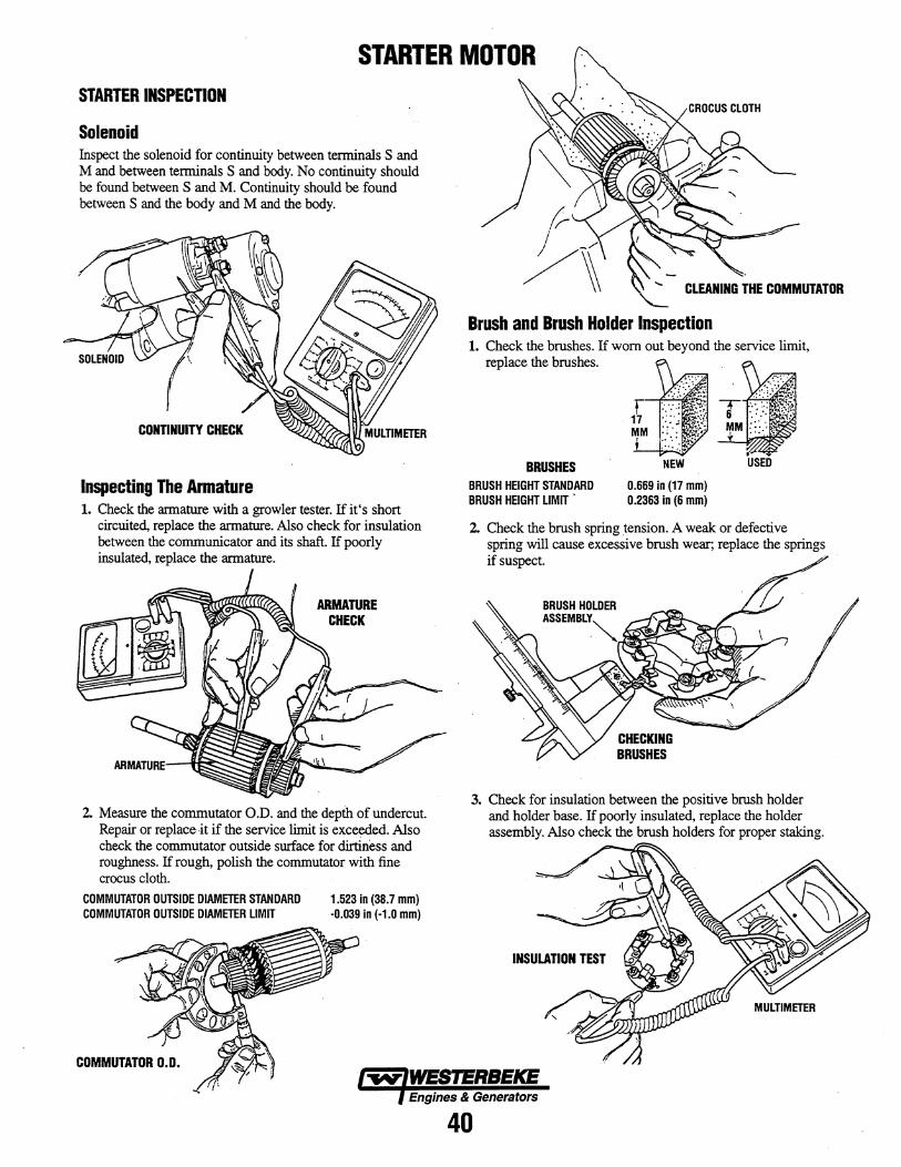
STARTER MOTOR STARTER INSPECTION
Solenoid Inspect the solenoid for continuity between tenninals S and M and between tenninals S and body. No continuity should be found between S and M. Continuity should be found between S and the body and M and the body.
Inspecting The Armature 1. Check the armature with a growler tester. If it's short
circuited, replace the armature. Also check for insulation between the communicator and its shaft. If poorly insulated, replace the armature.
ARMATURE CHECK
2. Measure the commutator 0.0. and the d~pih of undercut. Repair or replace it if the service limit is exce¢ed. Also check the commutator outside surface for dirtiness and roughness. If rough, polish the commutator with fine crocus cloth.
COMMUTATOR OUTSIDE DIAMETER STANDARD 1.523 in (38.7 mm) COMMUTATOR OUTSIDE DIAMETER LIMIT -0.039 in (-1.0 mm)
COMMUTATOR 0.0.
Brush and Brush Holder Inspection 1. Check the brushes. If worn out beyond the service limit,
replace the brushes.
BRUSHES BRUSH HEIGHT STANDARD BRUSH HEIGHT LIMIT •
0.669 in (17 mm) 0.2363 in (6 mm)
2. Check the brush spring tension. A weak or defective spring will cause excessive brush wear; replace the springs if suspect. ..
BRUSH HOLDER
ASSEMBLY '" ~~_ .....
~tr7
3. Check for insulation between the positive brush holder and holder base. If poorly insulated, replace the holder assembly. Also check the brush holders for proper staking.
Engines & Generators
40
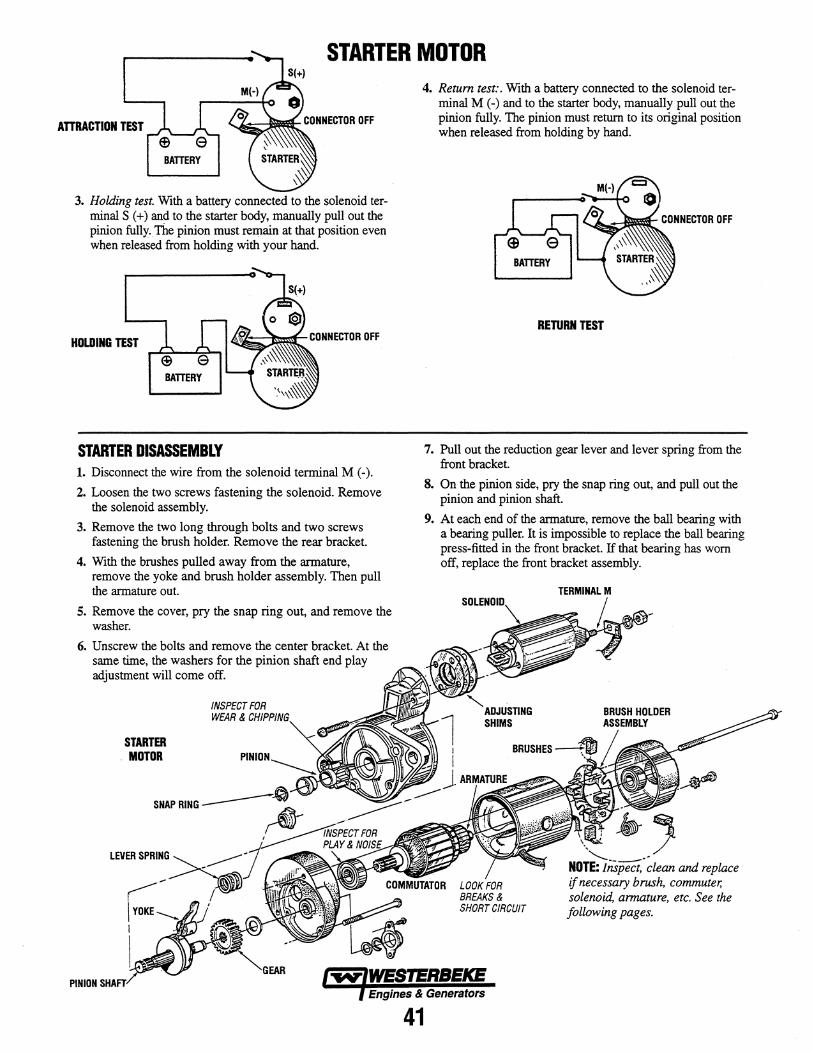
STARTER MOTOR
ATTRACTION TEST
3. Holding test. With a battery connected to the solenoid terminal S (+) and to the starter body, manually pull out the pinion fully. The pinion must remain at that position even when released from holding with your hand.
HOLDING TEST
STARTER DISASSEMBLY 1. Disconnect the wire from the solenoid terminal M (-).
2. Loosen the two screws fastening the solenoid. Remove the solenoid assembly.
3. Remove the two long through bolts and two screws fastening the brush holder. Remove the rear bracket.
4. With the brushes pulled away from the armature, remove the yoke and brush holder assembly. Then pull the armature out.
5. Remove the cover, pry the snap ring out, and remove the washer.
6. Unscrew the bolts and remove the center bracket. At the same time, the washers for the pinion shaft end play adjustment will come off.
PINION
STARTER . MOTOR
LEVER SPRING
INSPECT FOR WEAR & CHIPPING
4. Return test:. With a battery connected to the solenoid terminal M (-) and to the starter body, manually pull out the pinion fully. The pinion must return to its original position when released from holding by hand.
RETURN TEST
7. Pull out the reduction gear lever and lever spring from the front bracket.
S. On the pinion side, pry the snap ring out, and pull out the pinion and pinion shaft.
9. At each end of the armature, remove the ball bearing with a bearing puller. It is impossible to replace the ball bearing press-fitted in the front bracket. If that bearing has worn off, replace the front bracket assembly.
SOLENOID
'ADJUSTING SHIMS
.. ---.. ~ NOTE: Inspect. clean and replace if necessary brush. commuter; solenoid. armature, etc. See the following pages.
Engines & Generators
41
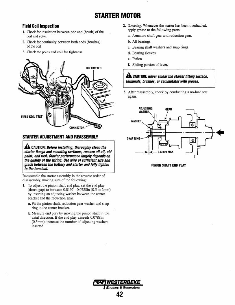
STARTER MOTOR Field Coil Inspection 1. Check for insulation between one end (brush) of the
coil and yoke.
2. Check for continuity between both ends (brushes) of the coil
3. Check the poles and coil for tightness.
MULTIMETER
FIELD COIL TEST
STARTER ADJUSTMENT AND REASSEMBLY
A CAUTION: Before installing, thoroughly clean the starter flange and mounting surfaces, remove all oil, old paint, and rust. Starter performance largely depends on the quality of the wiring. Use wire of sufficient size and grade between the battery and starter and fully tighten to the terminal.
Reassemble the starter assembly in the reverse order of disassembly, making sure of the following:
1. To adjust the pinion shaft end play, set the end play (thrust gap) to between 0.0197 - 0.0788in (0.5 to 2mm) by inserting an adjusting washer between the center bracket and the reduction gear.
a. Fit the pinion shaft, reduction gear washer and snap ring to the center bracket.
b. Measure end play by moving the pinion shaft in the axial direction. If the end play exceeds 0.0788in (O.5mm), increase the number of adjusting washers inserted.
2. Greasing. Whenever the starter has been overhauled, apply grease to the following parts:
a. Armature shaft gear and reduction gear.
b. All bearings.
c. Bearing shaft washers and snap rings.
d. Bearing sleeves.
e. Pinion.
f. Sliding portion of lever.
A CAUTION: Never smear the starter fitting surface, terminals, brushes, or commutator with grease.
3. After reassembly, check by conducting a no-load test again.
WASHER
SNAP RING
0.5 mm MAX
PINION SHAFT END PLAY
Engines & Generators
42
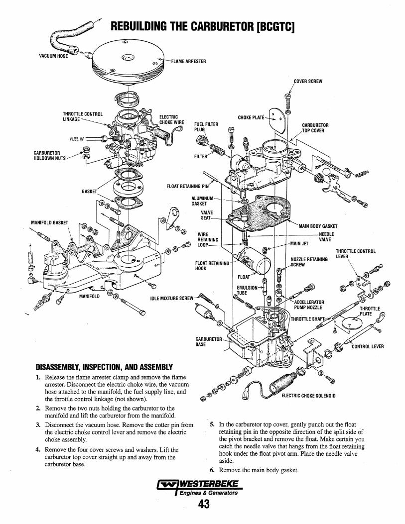
REBUILDING THE CARBURETOR [BCGTC]
FLAME ARRESTER
SCREW
CARBURETOR TOP COVER
ALUMINUM GASKET
IDLE MIXTURE SCREW
DISASSEMBLY, INSPECTION, AND ASSEMBLY 1. Release the flame arrester clamp and remove the flame
arrester. Disconnect the electric choke wire, the vacuum hose attached to the manifold, the fuel supply line, and the throttle control linkage (not shown).
2. Remove the two nuts holding the carburetor to the manifold and lift the carburetor from the manifold.
3. Disconnect the vacuum hose. Remove the cotter pin from the electric choke control lever and remove the electric choke assembly.
4. Remove the four cover screws and washers. Lift the carburetor top cover straight up and away from the carburetor base.
VALVE SEAT
____ NEEOLE VALVE
THROTTLE CONTROL LEVER
5. In the carburetor top cover, gently punch out the float retaining pin in the opposite direction of the split side of the pivot bracket and remove the float. Make certain you catch the needle valve that hangs from the float retaining hook under the float pivot arm. Place the needle valve aside.
6. Remove the main body gasket.
Engines & Generators
43
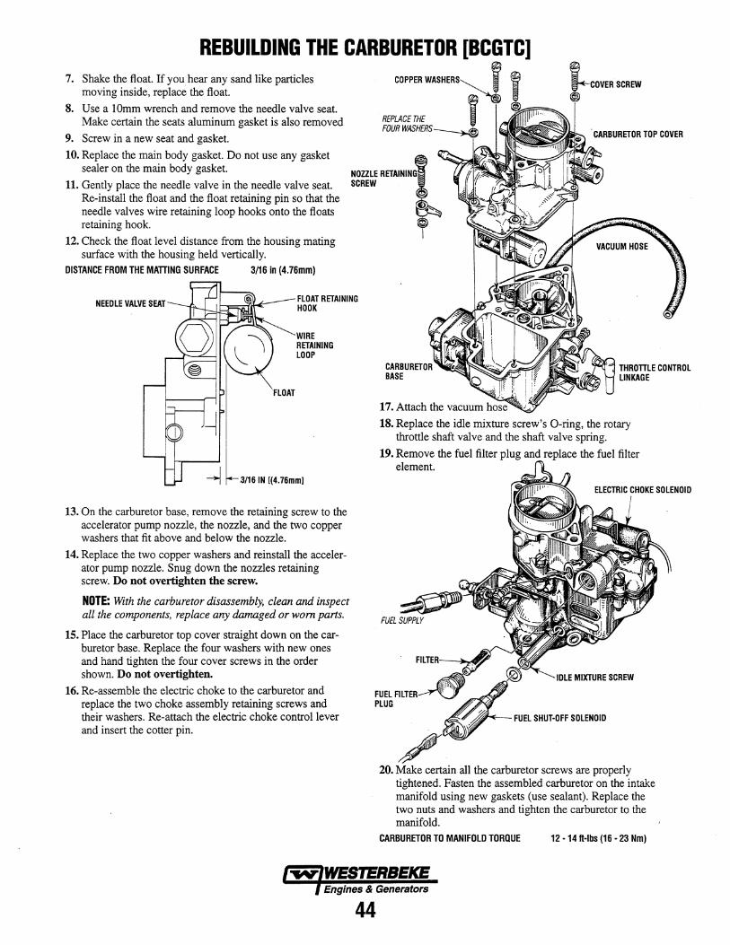
REBUILDING THE CARBURETOR [BCGTC] 7. Shake the float. If you hear any sand like particles
moving inside, replace the float.
8. Use a lOmm wrench and remove the needle valve seat. Make certain the seats aluminum gasket is also removed
9. Screw in a new seat and gasket.
10. Replace the main body gasket. Do not use any gasket sealer on the main body gasket.
11. Gently place the needle valve in the needle valve seat. Re-install the float and the float retaining pin so that the needle valves wire retaining loop hooks onto the floats retaining hook.
12. Check the float level distance from the housing mating surface with the housing held vertically.
DISTANCE FROM THE MATTING SURFACE 3/16 in (4.76mm)
COPPER WAlSHtII:S,-
REPLACE THE FOUR WASHERS
NOZZLE RETAINING SCREW
~""C~IV~R SCREW
, CARBURETOR TOP COVER
NEEDLE VALVE SEAT FLOAT RETAINING HOOK
FLOAT
WIRE RETAINING LOOP
,3/16 IN [(4.76mml
13. On the carburetor base, remove the retaining screw to the accelerator pump nozzle, the nozzle, and the two copper washers that fit above and below the nozzle.
14. Replace the two copper washers and reinstall the accelerator pump nozzle. Snug down the nozzles retaining screw. Do not overtighten the screw.
NOTE: With the carburetor disassembly, clean and inspect all the components, replace any damaged or worn parts.
15. Place the carburetor top cover straight down on the carburetor base. Replace the four washers with new ones and hand tighten the four cover screws in the order shown. Do not overtighten.
16. Re-assemble the electric choke to the carburetor and replace the two choke assembly retaining screws and their washers. Re-attach the electric choke control lever and insert the cotter pin.
CARBURETOR ........... '" BASE
18. Replace the idle mixture screw's O-ring, the rotary throttle shaft valve and the shaft valve spring.
19. Remove the fuel filter plug and replace the fuel filter element.
FUEL I"HI"L.-r
PLUG
~M-- FUEL SHUT-OFF SOLENOID
20. Make certain all the carburetor screws are properly tightened. Fasten the assembled carburetor on the intake manifold using new gaskets (use sealant). Replace the two nuts and washers and tighten the carburetor to the manifold.
CARBURETOR TO MANIFOLD TORQUE 12 -14 ft-Ibs (16 - 23 Nm)
Engines & Generators
44
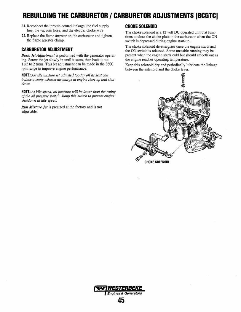
REBUILDING THE CARBURETOR I CARBURETOR ADJUSTMENTS [BCGTC] 21. Reconnect the throttle control linkage, the fuel supply
line, the vacuum hose, and the electric choke wire.
22. Replace the flame arrester on the carburetor and tighten the flame arrester clamp.
CARBURETOR ADJUSTMENT Basic Jet Adjustment is performed with the generator operating. Screw the jet slowly in until it seats, then back it out 1112 to 2 turns. This jet adjustment can be made in the 3600 rpm range to improve engine performance.
NOTE: An idle mixture jet adjusted too far off its seat can induce a sooty exhaust discharge at engine start-up and shutdown.
NOTE: At idle speed, oil pressure will be lower than the rating of the oil pressure switch. Jump this switch to prevent engine shutdown at idle speed.
Run Mixture Jet is presized at the factory and is not adjustable.
CHOKE SOLENOID The choke solenoid is a 12 volt DC operated unit that functions to close the choke plate in the carburetor when the ON switch is depressed during engine start-up.
The choke solenoid de-energizes once the engine starts and the ON switch is released. Some unstable running may be present when the engine starts cold but should smooth out as the engine reaches operating temperature.
Keep this solenoid dry and periodically lubricate the linkage between the solenoid and the choke lever.
Engines & Generators
45
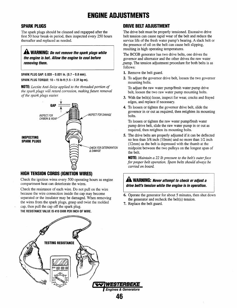
ENGINE ADJUSTMENTS SPARK PLUGS The spark plugs should be cleaned and regapped after the first 50 hour break-in period, then inspected every 250 hours thereafter and replaced as needed.
A WARNING: Do not remove the spark plugs while the engine is hot. Allow the engine to cool before removing them.
SPARK PLUG GAP: 0.028 - 0.031 in. (0.7 - 0.8 mm).
SPARK PLUG TORQUE: 10 -15 Ib-fl (1.5 - 2.31 kg-m).
NOTE: Loctite Anti-Seize applied to the threaded portion of the spark plugs will retard corrosion, making future removal of the spark plugs easier.
+ GAP~
INSPECT FOR CARBON & WEAR
INSPECTING SPARK PLUGS
INSPECT FOR DAMAGE
CHECK FOR DETERIORATION & DAMAGE
HIGH TENSION CORDS (IGNITION WIRES) Check the ignition wires every 500 operating hours as engine compartment heat can deteriorate the wires.
Check the resistance of each wire. Do not pull on the wire because the wire connection inside the cap may become separated or the insulator may be damaged. When removing the wires from the spark plugs, grasp and twist the molded cap, then pull the cap off the spark plug. THE RESISTANCE VALUE IS 410 OHM PER INCH OF WIRE.
DRIVE BELT ADJUSTMENT The drive belt must be properly tensioned. Excessive drive belt tension can cause rapid wear of the belt and reduce the service life of the fresh water pump's bearing. A slack belt or the presence of oil on the belt can cause belt slipping, resulting in high operating temperatures.
The BCGB generator has two drive belts, one drives the governor and alternator and the other drives the raw water
,pump. The tension adjustment procedure for both belts is as follows:
1. Remove the belt guard.
2. To adjust the governor drive belt, loosen the two governor mounting bolts.
To adjust the raw water pump/fresh water pump drive belt, loosen the two raw water pump mounting bolts.
3. With the belt(s) loose, inspect for wear, cracks and frayed edges, and replace if necessary.
4. To loosen or tighten the governor drive belt, slide the governor in or out as required, then retighten its mounting bolts.
To loosen or tighten the raw water pump/fresh water pump drive belt, slide the raw water pump in or out as required, then retighten its mounting bolts.
5. The drive belts are properly adjusted if it can be deflected no less than 3/& inch (IOmm) and no more than 112 inch (12mm) as the belt is depressed with the thumb at the midpoint between the two pulleys on the longest span of the belt.
NOTE: Maintain a 22 lb pressure to the belt's outer face for proper belt operation. Spare belts should always be carried on board.
A WARNING: Never attempt to check Dr adjust a drive belt's tension while the engine is in operation.
6. Operate the generator for about 5 minutes, then shut down the generator and recheck the belt(s) tension.
7. Replace the belt guard.
Engines & Generators
46
ENGINE ADJUSTMENTS ENGINE SPEED (HERTZ) ADJUSTMENT· BCGTC Governor The belt-driven, mechanically operated governor maintains the engine's rpm under various load conditions. Engine speed determines the hertz and voltage output of the generator.
Governor Adjustments Operate the generator to bring the unit up to operating temperature before adjusting the governor.
NOTE: If the governor is severely out of adjustment, manually adjust the linkage at no-load to obtain a safe output voltage before proceeding with the adjustment.
There are three adjusting points on the governor (see illustration).
1. IncreaselDecrease Speed Adjustment. This adjusting bolt sets the no-load speed of the engine. (The linkage arm between the governor arm and throttle lever should be adjusted to hold the throttle full open when the engine is not running.) Make sure this linkage moves freely and that the ball joint connectors are properly lubricated. Use graphite lube for this purpose. Disconnect the ball joint and apply graphite lube to the inside of the joint.
2. HuntinglReguiatitJn Adjustment. If the variation in engine speed between no-load and full-load is too great, adjust this eye bolt to draw the spring closer to the lever hub. 1be increase/decrease speed bolt may need to be adjusted as well.
If the governor surges under load, adjust this eye bolt to move the spring away from the lever hub (check speed adjustment).
3. Bumper Screw Adjustment. This screw is used to remove a no-load surge ONLY. NEVER turn the bumper screw into the governor so far that it increases the no-load speed.
Governor Maintenance 1. Periodically lubricate the linkage arm attaching points at
the governor arm and throttle lever. Use a graphite lubricant or equivalent.
NOTE: Free movement of this linkage arm is important for proper governor/throttle operation.
2. Governor oil capacity - 3 ounces 10/30 engine oil.
NOTE: Do not overfill the governor.
3. Change the governor oil every 250 hours of operation.
To change the oil, remove the governor from the engine, remove the oil fill and the fill level plug, and drain all the oil. Reinstall on the engine and fill with 3 ounces of 10/30 engine oil. Replace the plugs.
4. Periodically adjust the governor belt tension (see DRIVE BELTS ADJUSTMENT). Since belts stretch slightly, this stretching will, to some degree, affect the govenor's action.
REGULATION ADJUSTMENT
GOVERNOR [BCGTC ONLY)
ALL
OIL (UNDER)
GOVERNOR BELT
Engines & Generators
47

ENGINE ADJUSTMENTS TESTING OIL PRESSURE To test the oil pressure, remove the oil pressure sendor from the oil manifold and install a mechanical oil pressure gauge in its place. After warming up the engine and set the engine speed at 3600 rpm read the oil pressure gauge. OIL PRESSURE Between 30 and 40 psi at 3600 rpm.
Note: A newly started (cold) engine may have an oil pressure up to 70 or 80 psi. A warmed engine can have an oil pressure as low as 30 psi. Oil pressure will vary depending on the load placed on the generator.
OIL GALLERY
LOW OIL PRESSURE The specified safe minimum oil pressure is 4.3 + 1.4 psi (0.3 + 0.1 kglcm2). A gradual loss of oil pressure usually indicates worn bearings. For additional information on low oil pressure readings, see the ENGINE TROUBLESHOOTING chart.
OIL PRESSURE SWITCH The generator is fitted with an oil pressure shutdown switch. Should the engine's oil pressure drop below the safe minimum, the switch will shut the engine down to prevent damage by interrupting the DC voltage to the K2 run relay.
NORMALLY OPEN 5 PSI RATED
+ ~ I BATTERY
... PRESSURE
ENGINE COMPRESSION TEST 1. To check the engine's compression pressure, warm up
the engine then shut it down.
2. Remove the three spark plug caps and remove the three spark plugs.
3. Install a compression adapter and gauge in the spark plug hole.
4. Close off the raw water intake seacock.
5. Crank the engine with the start motor and unplug the ignition coil and allow the compression gauge to reach a maximum reading and record.
6. Measure the compression pressure for all the cylinders. Ensure that compression pressure differential for each cylinder is within the specified unit. Compression pressure should not differ by more than 14 psi (100Kpa)
7. If a cylinder's compression or pressure differential is below the limit, add a small amount of engine oil through the spark plug hole and repeat steps 4 and 5.
(a) If additional oil causes an increase of pressure, the piston ring and/or cylinder wall may be torn or damaged.
(b) If additional oil does not increase compression pressure suspect poor valve contact, valve seizure, or valve wear.
8. Reinstall three plugs and ignition wires.
9. Open the raw water thru seacock.
COMPRESSION PRESSURE 178 PSI [1260Kpa] AT 400 RPM
COMPRESSION GAUGE (TYPICAL)
ADAPTER
~
Engines & Generators
48
ENGINE ADJUSTMENTS VALVE CLEARANCE ADJUSTMENT NOTE: Retorque the cylinder head bolts before adjusting the engine's valves (see TORQUING THE CYLINDER HEAD BOLTS).
1. Remove the rocker cover and gasket.
2. Rotate the crankshaft in the normal direction of rotation, placing the No.1 piston at the top of its compression stroke with the exhaust and intake valves completely closed. Adjust the intake valve for No.2 cylinder, and the intake valve for No.3 cylinder (see chart).
3. Rotate the crankshaft 180° in its normal direction of rotation. Locate the piston in No. 1 cylinder at the top of its exhaust stroke. Adjust the intake valve for No.2 cylinder and the exhaust valve for No.3 cylinder (see chart).
CYLINDER # CRANK ANGLE
1 2 3 When No. 1 piston is set at top of IN • • compression stroke • • EX When No. 1 piston is positioned IN • at top of exhaust stroke
EX • 4. Replace the rocker cover along with a new rocker cover
gasket.
ROCKER COVER TORQUE: 2.9-5.1Ib-ft (0.4-0.7 Nm)
VALVE CLEARANCE
VALVE CLEARANCE: INTAKE .00S inches (0.2omm) EXHAUST .. 012 inches (0.30mm)
IGNITION TIMING 1. Attach a timing light to the #1 spark plug and mark the
front timing pointer to indicate 18°. Locate the timing mark on the crankshaft pulley and mark it with white chalk or a crayon.
2. Start the engine and warm it up to its normal operating temperature. Make sure the generator is operating without a load on it.
3. Using the timing light, align the timing mark in the front crankshaft pulley so it is just slightly before tD.e first timing pointer. Do this by loosening and slowly rotating the distributor body. Refer to the timing specifications:
TIMING SPECIFICATIONS: 1So BTDC at 3600 rpm (no load on generator)
IGNITION TIMING
TORQUING THE CYLINDER HEAD BOLTS After the initial break-in period (approximately 50 hours), the cylinder head bolts should be re-torqued.
Tighten the cylinder head bolts according to the sequence shown. Make sure the engine is cold when this is done, and loosen one head bolt one-half turn and then tighten it between 43 - 51lb-ft (60 - 70 Nm). Then proceed to the next head bolt in the sequence. Tighten the RS (rocker cover stud) securely.
ENGINE~ FRONT
7
ENGINE TIMING BELT
2
3
. The engine timing belt should be replaced at 1000 operating hours. Refer to ENGINE TIMING BELT INSTRUCTIONS FOR INSPECTING AND REPLACING.
Engines & Generators REVISED JULY 2004
49
COMPONENT TESTING GENERAL All DC voltage measurements are made to the engine battery negative ground point unless specified otherwise. In making test measurements, make sure that a good ground for the meter is established, preferably the point where the negative battery is connected to the engine. Battery positive voltage is indicated as B+ and should measure no less than 11.5 volts.
AC voltage measurements should be made with a true RMS AC meter to insure measurement accuracy.
ENGINE.Gnu\lI1u --"<ctttl
GROUND AND B(+) CONNECTIONS
RELAYS The relays used in the control system have coils which are polarized by the fact that they have internal free wheeling suppression diodes across them. Relay coil terminal 86 must be maintained (+), terminal 85(-). The relay coil is rated 12V DC, and the coil resistance is typically 85 ohms. With B+ on terminal 86, direct grounding of terminal 85 is permissible for testing purposes.
RELAYS
RELAY TERMINALS
REMOVE THIS RELAY CONNECTOR
Engines & Generators
50
TAP THE GROUND CONNECTION TO THE TERMINAL. RELAY SHOULD
.--. ____ "CLICK" ON.
TO B(+)
TESTING THE RELAY TERMINALS
TESTING COIL RESISTANCE
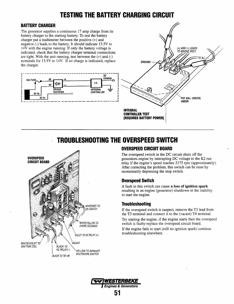
TESTING THE BATTERY CHARGING CIRCUIT BAnERY CHARGER The generator supplies a continuous 17 amp charge from its battery charger to the starting battery. To test the battery charger put a multimeter between the positive (+) and negative (-) leads to the battery. It should indicate 13.5V to 14V with the engine running. If only the battery voltage is indicated, check that the battery charger terminal connections are tight. With the unit running, test between the (+) and (-) terminals for 13.5V to 14V. If no charge is indicated, replace the charger.
r - -~ - - - - ----------- - - -- - - --- - -- - - -- -..,- - ---, I DC I : 30A . CHARGE t I I I I I I I I
I RECTIFIER CONTROLLER.:
I Hz : L ___ ..:... _______________________ ....1
INTEGRAl CONTROLLER TEST [REQUIRES BATTERY POWER]
""-PDT ADJ. (VOLTS) UNDER
TROUBLESHOOTING THE OVERSPEED SWITCH
OVERSPEED CIRCUIT BOARD
BLACK TO TB116
TO EXHAUST SHUTDOWN SWITCH
OVERSPEED CIRCUIT BOARD The overspeed switch in the DC circuit shuts off the generators engine by interupting DC voltage to the K2 run relay if the engine's speed reaches 2175 rpm (approximately). After correcting the problem, this switch can be reset by momentarily depressing the stop switch.
Overspeed Switch A fault in this switch can cause a loss of ignition spark resulting in an engine (generator) shutdown or the inability to start the engine.
Troubleshooting If the overspeed switch is suspect, remove the T3 lead from the T3 terminal and connect it to the (vacant) T4 terminal.
Try starting the engine, if the engine starts then the overspeed switch is faulty-replace the overspeed circuit board.
If the engine fails to start (still no ignition spark) continue troubleshooting elsewhere.
Engines & Generators
51
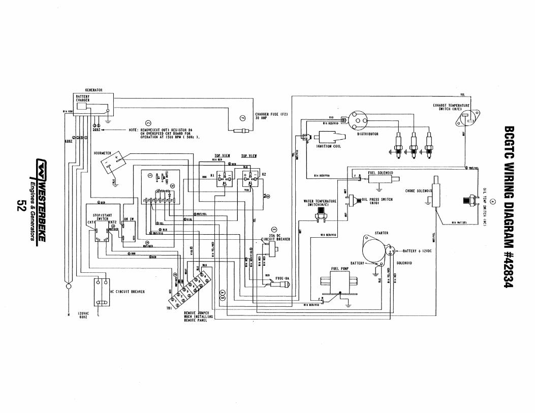
~ IQ 5'
c.n:R NQI>
fi,> ::J ~ III Q !il
GENERATOR
BATTERY m , ..
CHARGER EXHAUST TEMPERATURE
SWITCH (N~/C) """ ,,,... L-'= J CHARGER FUSE (FZ) '" ~ \ ~ e 30 AMP 0 o,-Crl)\-------, ~,~ ~ e ,w; '" '''IVI' ,(). ~ I 0 ruu • HOTE: REMOVE(CUT OUT) RESISTOR RG ~ U- cC> ~RIBUTOR ,l, ,l, :: ON OVERS PEED CKT BOARD FOR - .
,,<zICi OPERATION AT 1500 RPM ( SOH. l.
WU' IGNITION COil r.aJ;J "~ ,'LlaJl - 'Ir--.,- 'I, ~ 'I, .,.. HOURMETER IOL1lEJ IOL1lEJ ~ ." ... ."
~ 114 IU I-,- ,V Q) ". ',!!Il!l ,-- $~ FUEL SOLENOID - r;:;. It R~ • KI + - + - KZ ",""VI, rJl D
\:...:I [pi U;i 01 LiI •• '5 .. IS ~ 0 0 II I
~ - e VI, i ~ CHOKE SOlENOI[ g: rt'lt- ~ be '~Oll PRESS SWITCH ,-I dlN ~ • ~ • 1= lATER TEMPERATURE = (N/O) ~ ®m ,-- 1"1/"" ~ ~ ~ ~ SWlTCH(H/C) _,
STOPISTART b,VlOl I!!"'IJU ~ 6 5 1\ 'IS ,,"",' CKTI~ KTZ ION sw l<!l", '" u .,
"--- In n~' <!llll e ~ STARTER d
r'IUnUh LW e c ' -rm~EAKER II. II."" ~ ~ 'I .. f,,,, ~ ~ H-J ~. ~ATTERY + IZVDC
Q)'" >.: ~ ; BATTERY~ SOLENOID
.~ F· • FUEL PUMP iT '--------ortrS , '~ ~ ~ i==l ~, ,
AC CIRCUIT BREAKER ,~:: i>, v. ~ ~ ~
~PJ V, ~t!~t=~~~~~~~~~~~~~'~"~'~"~"~"~~~=~ J,~~~~~~~~~ ____________ j '-- TBI
" IZOVAC , REMOVE UMPER IG
REMOTE PANEL
a::I n C) ... n :e -:a -~ Z
r C) ~e CI :a -~ :I:a n C)
= :s:: =11= .a::a. N CO W .a::a.
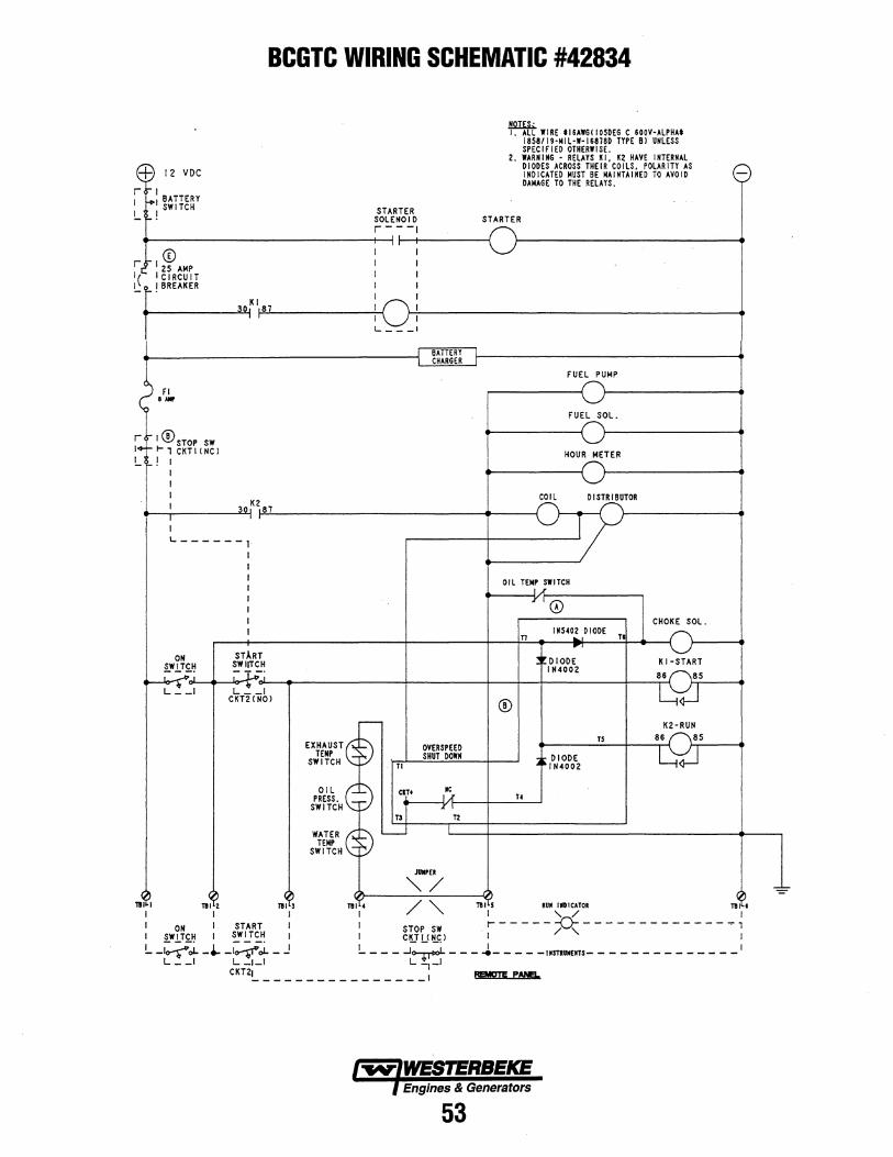
BCGTC WIRING SCHEMATIC #42834
:-+: 12 VDC
r 1 I -+1 BATTERY !.... !SWITCH
CD r, 125 AMP Ie I CIRCUIT
STARTER SOLENOID r-- -I
I I I I I I I I I I
J!.QI.E1;. I. ALL WIRE tl6AW6(10SDE6 C fOOY-ALPHAt
18S8119-MIL-W-16878D TYPE BI UNLESS SPEC I F I ED OTHERW I SE.
2. WARN I N6 - RELAYS K I. K2 HAYE INTERNAL DIODES ACROSS THEIR COILS. POLARITY AS INDICATED MUST BE MAINTAINED TO AYOID DAMAGE TO THE RELAYS.
STARTER
!....~ ~K1187 ~--------------~I~ r71---------------------------------------------. I I
FI .... r I ®STOP SW 1+ 1-1 CKTI (NCI !.... ! I
I I I
1... ___ 1
I 30,K2 87 .--r-I------~ ~--------------------------._--~
I 1...------ 1.
I I
FUEL PUMP
FUEL SOL.
HOUR METER
COIL DISTRIBUTOR
1 I I I I I I
OIL TEM; ;WlTCH
r 0
n I"S40~ DIODE
TI r-
CHOKE SOL.
DIODE IN4002
ON ST.l.RT SWITCH SWIITCH KI-START
.-~-~~--,-~·~~~-~~~---~·--~--------------r_--------~--~_+----------~--~8r{6 f8r5 ____ ~ ~_I L~_I
CKT2(NO)
OIL L.
l:f~h '"T".
TI
OYERSPEED SHUT DOWN
r n TZ
JUllPEI
® K2-RUN
T5
DIODE IN4002
86 8S ~~-,-{L,~~
T4
"'-/ ~ 1I~~ 1I~~ 111 ~ 111 4 / " 111 5 RIIII IIIIIICATOR n~~.
I I I" I " / I I ON I START I STOP SW r- - - - - - -D.- - - - - - - - - - - - - - ~ , I SWITCH I SWITCH I I CUl.!!!£1 . I / " I
!.... -~.,i. _ ... -~.,i. - .! !.... - - - .J~ - - - J- - - - -IMSTRUMElTS- - - - - - - - - - - - - -I L __ I L_I_I L-,_I
CKT2!.. _______________ I I!EM!m! PAN!!!..
Engines & Generators
53
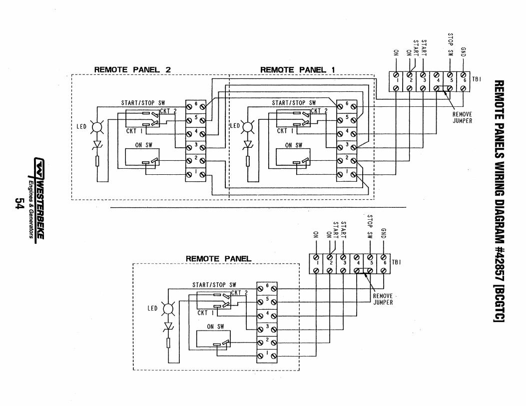
c.n ~
~I l!.4 Qoiil
~iI ~bI Q~ iilll'l
r----I I
• I I I I I I I I I I I I I
LED
n~lvlu I ~ r "'I"~L. " nr::;IYIu, ,r::; r """r::;L. , ------------------------------------T--------------------------------------\
I I
! \ \
\ \
,,~ 6.c"\ I
START/STOP SW i~6~ / \ START/STOP SW \ \
~ " CKT 2
!uo*-,., CKT 2 'J '-7 \
\ I
C;:I~ ~5~ I C;:I~ ~5~ / \
I - I \ \
CKT I I I~ 4~ CKT I I ~4~ \
- 'J '-7' \
ON SW ~3~ ON SW ~3~ V' '-- r{..l '--
I . AI I 1:;:3~1 IJ I~ 2 IC'\
11 ~2~ 1:;:3 VJ I !'7 '-J '7 '-" i'-
I '~ I~ - I ~I.c'I \.Y '-" r'\ '-- '-
J L ________ -----~--------------------------------------- ___________________________ .
(.I)
-l (.I) (.I) 0 -l -l -0
0 ~~
0::0 ::0 (.I)
:z: :z -l '-l ~
REMOTE PANEL r---------------------------_·---------------,
0 :z:
e: ,~
G') Z 0
REMOVE· ~ \ JUMPER
LEO
------- ____________________________________ J
en -l
(.I) (.I) 0 -l -l -0 ~~ G') o ::0 ::0 (.I) :z:
Z -\-l :0: 0
~ ~ ~ ~ ~ TBI ,~ ,~ ,~ ::"."0 ,~
\1 \ ,
REMOV JUMPE
TROUBLESHOOTING GUIDE FOR EFI COMPONENTS [BCGTE] ENGINE OPERATING SYSTEM DESCRIPTION The engine/generator is equipped with an electronic speedregulated, fuel injected control system. Engine speed is maintained constant by varying the amount of air induced past a throttle plate into the intake manifold. The throttle plate position is controlled by a rotary proportional actuator energized from a closed loop control circuit whose signal input is from a magnetic pickup-type speed sensor.
Fuel is metered to the engine intake manifold by a central port-type fuel injector system where the amount of fuel injected is primarily determined by the engine speed, the engine load, the engine temperature and the intake air temperature. Fuel is deliv.ered to the engine by a high pressure fuel pump. The fuel pressure drop across the injector is maintained constant by a fuel pressure regulator which is ported to the intake manifold to compensate for pressure variations as a result of engine load changes.
Air-fuel management as well as engine operational functions are performed by an embedded electronic control unit (BCU). Engine/generator control functions (starting and stopping) are inputted from a remote control panel or from the engine START/OFF switch to the ECU. The ECU then sets the required operational parameters necessary for the running of the engine.
ECU CONTROL CIRCUIT DESCRIPTION The BCU is entirely contained on a single printed circuit board. It uses as the principal engine controlling element a micro controller integrated circuit (MCU). The MCU is a self-contained microcomputer with an internal central processor unit (CPU), read-only memory (ROM), random access memory (RAM), an analog to digital converter (AID), as well as programmable digital input/output ports (I/O). The MCU also contains an internal timer which provides the required timing functions necessary for engine control (i.e., oil pressure switch, closure time delay, etc.).
The output driver in the ECU which controls the relays (Kl, K2) and the remote control panel indicator lamp(s) is one which has internal current limiting capability of its outputs, and will tum itself off should such an over-current condition occur. Therefore, the indicator lamp(s) which are used to indicate the engine status must be of the 12V, LED type and not of the tungsten filament type whose low cold resistance can and will (in most cases), create a current surge which will cause an over-current condition which will tum off these outputs. If such a condition should occur, tum off the power to the ECU, remove the cause of the condition, then resume normal operation.
The ROM of the MCU contains the program from which the engine is controlled. The MCU measures and monitors the status of the engine through various inputs and then sets accordingly the outputs which control the engine. The MCU has direct control of the amount of the fuel injected as well as some control of the throttle position. The actual position of the throttle plate actuator for speed control however, is determined by a proportional, integral and derivative (PID) analog closed loop control circuit. The MCU monitors the engine speed and will shut down the engine in case an overspeed condition should ever occur. In addition, the ECU has a safety backup overspeed circuit in the unlikely event that the MCU fails to respond.
The following text provides a detailed description and a troubleshooting chart of this control circuit.
A CAUTION: Before performing the test procedures in this manual, disconnect the AC voltage by thrOwing off the circuit breaker at the control panel and unplugging any shore power cords.
Engines & Generators
55
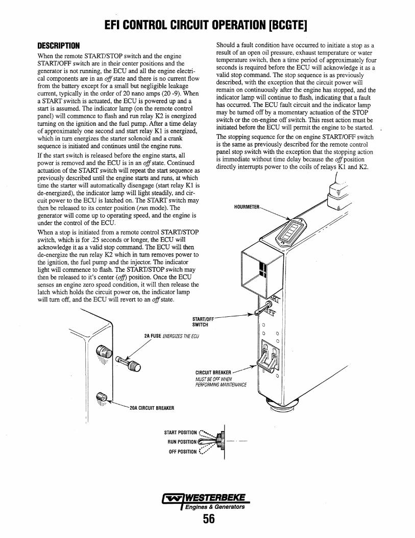
EFI CONTROL CIRCUIT OPERATION [BCGTE]
DESCRIPTION When the remote START/STOP switch and the engine START/OFF switch are in their center positions and the generator is not running, the ECU and all the engine electrical components are in an off state and there is no current flow from the battery except for a small but negligible leakage current, typically in the order of 20 nano amps (20 -9). When a START switch is actuated, the ECU is powered up and a start is assumed. The indicator lamp (on the remote control pan~l) will co~~~ce to flash and run relay K2 is energized turnmg o~ the IgrutlOn and the fuel pump. After a time delay of approXImately one second and start relay Kl is energized, which in turn energizes the starter solenoid and a crank sequence is initiated and continues until the engine runs.
If the start switch is released before the engine starts, all power is removed and the ECU is in an off state. Continued actuation of the START switch will repeat the start sequence as previously described until the engine starts and runs, at which time the starter will automatically disengage (start relay Kl is de-energized), the indicator lamp will light steadily, and circuit power to the ECU is latched on. The START switch may then be released to its center position (run mode). The generator will come up to operating speed, and the engine is under the control of the ECU.
When a stop is initiated from a remote control START/STOP switch, which is for .25 seconds or longer, the ECU will acknowledge it as a valid stop command. The ECU will then de-energize the run relay K2 which in tum removes power to the ignition, the fuel pump and the injector. The indicator light will commence to flash. The START/STOP switch may then be released to it's center (ofJ) position. Once the ECU senses an engine zero speed condition, it will then release the la~ch which holds the circuit power on, the indicator lamp WIll tum off, and the ECU will revert to an off state.
Should a fault condition have occurred to initiate a stop as a result of an open oil pressure, exhaust temperature or water tempera~re sw~tch, then a time period of approximately four sec?nds IS requIred before the ECU will acknowledge it as a valId .stop co~and. The stop sequence is as previously descnbed, wIth the exception that the circuit power will ~e~ain on continuously after the engine has stopped, and the mdicator lamp will continue to flash, indicating that a fault has occurred. The ECU fault circuit and the indicator lamp may be turned off by a momentary actuation of the STOP switch or the on-engine off switch. This reset action must be initiated before the ECU will permit the engine to be started.
The stopping sequence for the on engine START/OFF switch is the same as previously described for the remote control ?~el sto~ swit~h with .the exception that the stopping action I~ Imme~ate WIthOUt tIme delay because the offposition dIrectly mterrupts power to the coils of relays KI and K2.
HOURMETER
START/OFFSWITCH
20A CIRCUIT BREAKER
MUST BE OFF WHEN PERFORMING MAINTENANCE
START POSITION ( •••• ............ ~ .... RUN POSITION _, •• ' "
OFF POSITION (./
Engines & Generators
56
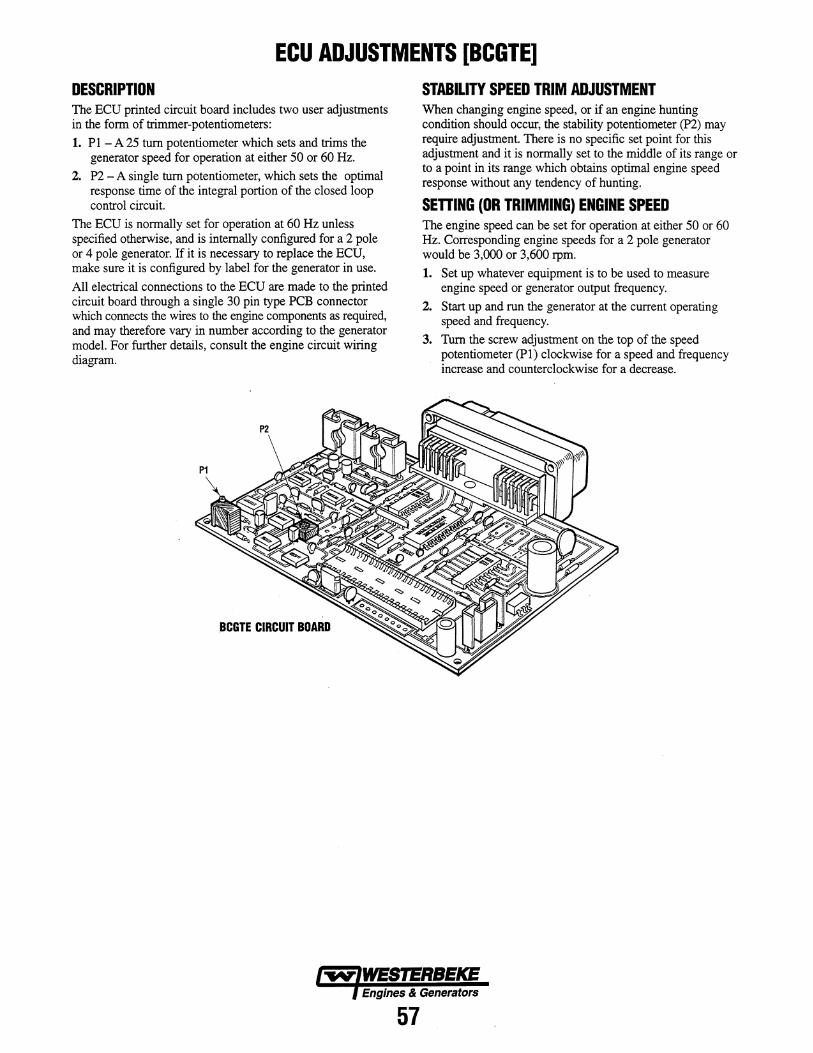
ECU ADJUSTMENTS [BCGTE] DESCRIPTION The ECU printed circuit board includes two user adjustments in the fonn of trimmer-potentiometers:
1. PI - A 25 turn potentiometer which sets and trims the generator speed for operation at either 50 or 60 Hz.
2. P2 - A single tum potentiometer, which sets the optimal response time of the integral portion of the closed loop control circuit.
The ECU is nonnally set for operation at 60 Hz unless specified otherwise, and is internally configured for a 2 pole or 4 pole generator. If it is necessary to replace the ECU, make sure it is configured by label for the generator in use.
All electrical connections to the ECU are made to the printed circuit board through a single 30 pin type PCB connector which connects the wires to the engine components as required, and may therefore vary in number according to the generator model. For further details, consult the engine circuit wiring diagram.
BCGTE CIRCUIT BOARD
STABILITY SPEED TRIM ADJUSTMENT When changing engine speed, or if an engine hunting condition should occur, the stability potentiometer (P2) may require adjustment. There is no specific set point for this adjustment and it is nonnally set to the middle of its range or to a point in its range which obtains optimal engine speed response without any tendency of hunting.
SEnlNG (OR TRIMMING) ENGINE SPEED The engine speed can be set for operation at either 50 or 60 Hz. Corresponding engine speeds for a 2 pole generator would be 3,000 or 3,600 rpm.
1. Set up whatever equipment is to be used to measure engine speed or generator output frequency.
2. Start up and run the generator at the current operating speed and frequency.
3. Tum the screw adjustment on the top of the speed potentiometer (PI) clockwise for a speed and frequency increase and counterclockwise for a decrease.
Engines & Generators
57
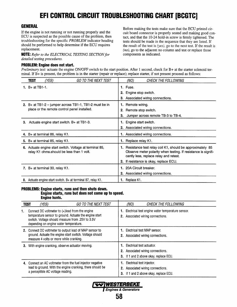
EFI CONTROL CIRCUIT TROUBLESHOOTING CHART [BCGTC] GENERAL If the engine is not running or not running properly and the BCU is suspected as the possible cause of the problem, then troubleshooting for the specific PROBLEM indicator heading should be performed to help determine if the BCU requires replacement. NOTE: Refer to the ELECTRICAL TESTING SECTION for detailed testing procedures.
PROBLEM: Engine does not start.
Before making the tests make sure that the BCU printed circuit board connector is properly seated and making good contact, and that the 10-24 hold-in screw is firmly tightened. The tests should be made in the sequence that they are listed. If the result of the test is (yes), go to the next test. If the result is (no), go to the adjacent no column and test or replace those components as indicated.
Preliminary test: actuate the engine ON/OFF switch to the start position. After 1 second, check for B+ at the starter solenoid terminal. If B+ is present, the problem is in the starter (repair or replace); replace starter, if not present proceed as follows:
TEST (YES) GO TO THE NEXT TEST
1. B+ atTB1-1. 1.
2.
3.
2. B+ at TB1-2 - jumper across TB1-1, TB1-2 must be in 1. place or the remote control panel installed. 2.
3.
3. Actuate engine start switch. B+ at TB 1-3. 1.
2.
4. B+ at terminal 86, relay K1. 1.
5. B+ at terminal 85, relay K1. 1.
6. Actuate engine start switch. Voltage at terminal 85, 1. relay K1 ohms.should be less than 1 volt.
2.
7. B+ at terminal 30, relay K1. 1.
2.
8. Actuate engine start switch. B+ at terminal 87, relay K1. 1.
PROBLEMS: Engine starts, runs and then shuts down. Engine starts, runs but does not come up to speed. Engine hunts.
(NO) CHECK THE FOLLOWING
Fuse.
Engine stop switch.
Associated wiring connections.
Remote wiring.
Remote stop switch.
Jumper across remote TB-3 to TB-4.
Engine start switch.
Associated wiring connections.
Associated wiring connections.
Replace relay K1.
Resistance test relay coil K1, should be approximately 85 Observe meter polarity when testing. If resistance is signifi-cantly less, replace relay and retest.
If resistance is okay, replace ECU.
20A Circuit breaker.
Associated wiring connections.
Replace K1.
TEST (YES) GO TO THE NEXT TEST (NO) CHECK THE FOLLOWING
1. Connect DC voltmeter to (+)Iead from the engine temperature sensor to ground. Actuate the engine start switch. Voltage should measure from .25V to 3.5V depending on engine water temperature.
2. Connect DC voltmeter to output lead of MAP sensor to ground. Actuate the engine start switch. Voltage should measure 4 volts or more while cranking.
3. With engine cranking, observe actuator moving.
4. Connect an AC voltmeter from the fuel injector negative lead to ground. With the engine cranking, there should be a perceptible AC voltage reading.
1. Electrical test engine water temperature sensor.
2. Associated wiring connections.
1. Electrical test MAP sensor.
2. Associated wiring connections.
1. Electrical test actuator.
2. Associated wiring connections.
3. If 1 and 2 above okay, replace ECU.
1. Electrical test injector.
2. Associated wiring connections.
3. If 1 and 2 above okay, replace ECU.
Engines & Generators
58
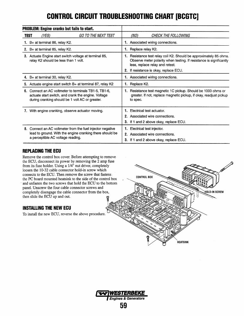
CONTROL CIRCUIT TROUBLESHOOTING CHART [BCGTC]
PROBLEM: Engine cranks but fails to start.
TEST (YES) GO TO THE NEXT TEST
1. B+ at terminal 86, relay K2.
2. B+ at terminal 85, relay K2.
3. Actuate Engine start switch voltage at terminal 85, relay K2 should be less than 1 volt.
4. B+ at terminal 30, relay K2.
5. Actuate engine start switch B+ at terminaI8?, relay K2
6. Connect an AC voltmeter to terminals TB1-5, TB1-6, actuate start switch, and crank the engine. Voltage during cranking should be 1 volt AC or greater.
7. With engine cranking, observe actuator moving.
8. Connect an AC voltmeter from the fuel injector negative lead to ground. With the engine cranking there should be a perceptible AC voltage reading.
REPLACING THE ECU Remove the control box cover. Before attempting to remove the ECU, disconnect its power by removing the 2 amp fuse from its fuse holder. Using a 114" nut driver, completely loosen the 10-32 cable connector hold-in screw which connects to the ECU. Then remove the screw that fastens. the PC board mounted heatsink to the side of the control box
. and unfasten the two screws that hold the ECU to the bottom panel. Unscrew the four cable connector screws and completely disengage the cable connector from the box, then slide the ECU up and out.
INSTALLING THE NEW ECU To install the new ECU, reverse the above procedure.
(NO) CHECK THE FOLLOWING
1. Associated wiring connections.
1. Replace relay K2.
1. Resistance test relay coil K2. Should be approximately 85 ohms. Observe meter polarity when testing. If resistance is significantly less, replace relay and retest.
2. If resistance is okay, replace ECU.
1. Associated wiring connections.
1. Replace K2.
1. Resistance test magnetic 1 C pickup. Should be 1000 ohms or greater. If not, replace magnetic pickup, if okay, readjust pickup
to spec.
1. Electrical test actuator.
2. Associated wire connections.
3. If 1 and 2 above okay, replace ECU.
1. Electrical test injector.
2. Associated wire connections.
3. If 1 and 2 above okay, replace ECU.
Engines & Generators
59
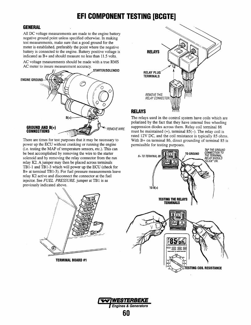
EFI COMPONENT TESTING [BCGTE] GENERAL All DC voltage measurements are made to the engine battery negative ground point unless specified otherwise. In making test measurements, make sure that a good ground for the meter is established, preferably the point where the negative battery is connected to the engine. Battery positive voltage is indicated as B+ and should measure no less than 11.5 volts.
AC voltage measurements should be made with a true RMS AC meter to insure measurement accuracy.
ENGINE GRI1UND.....:~Htlrr((f;~'!il
GROUND AND B(+) CONNECTIONS
There are times for test purposes that it may be necessary to power up the ECU without cranking or running the engine (i.e. testing the MAP of temperature sensors, etc.). This can be best accomplished by removing the wire to the starter solenoid and by removing the relay connector from the run relay K2. Ajumper may then be placed across terminals TBl-l and TBl-3 which will power up the ECU (check for B+ at terminal TBl-3). For fuel pressure measurements leave relay K2 active and disconnect the connector at the fuel injector. See FUEL PRESSURE. jumper at TB 1 is as previously indicated above.
TERMINAL BOARD #1
RElAYS
REMOVE THIS RELAY CONNECTOR.
RELAYS The relays used in the control system have coils which are polarized by the fact that they have internal free wheeling suppression diodes across them. Relay coil terminal 86 must be maintained (+), terminal 85(-). The relay coil is rated 12V DC, and the coil resistance is typically 85 ohms. With B+ on terminal 86, direct grounding of termihal 85 is permissible for testing purposes.
TESTING THE RElAYS TERMINALS
Engines & Generators
60
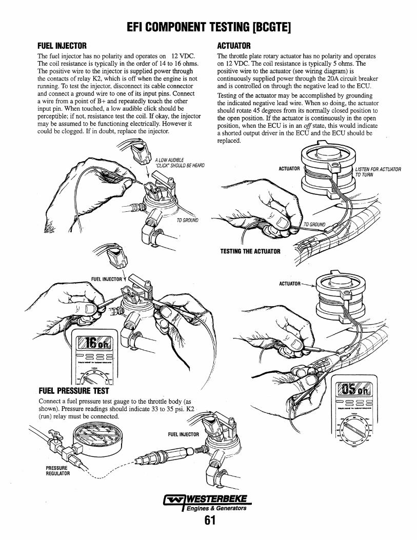
EFI COMPONENT TESTING [BCGTE] FUEL INJECTOR The fuel injector has no polarity and operates on 12 VDC. The coil resistance is typically in the order of 14 to 16 ohms. The positive wire to the injector is supplied power through the contacts of relay K2, which is off when the engine is not running. To test the injector, disconnect its cable connector and connect a ground wire to one of its input pins. Connect a wire from a point of B+ and repeatedly touch the other input pin. When touched, a low audible click should be perceptible; if not, resistance test the coil. If okay, the injector may be assumed to be functioning electrically. However it could be clogged. If in doubt, replace the injector.
FUEL PRESSURE TEST Connect a fuel pressure test gauge to the throttle body (as
ACTUATOR The throttle plate rotary actuator has no polarity and operates on 12 VDC. The coil resistance is typically 5 ohms. The positive wire to the actuator (see wiring diagram) is continuously supplied power through the 20A circuit breaker and is controlled on through the negative lead to the ECD.
Testing of the actuator may be accomplished by grounding the indicated negative lead wire. When so doing, the actuator should rotate 45 degrees from its normally closed position to the open position. If the actuator is continuously in the open position, when the ECU is in an off state, this would indicate a shorted output driver in the ECU and the ECU should be replaced.
shown). Pressure readings should indicate 33 to 35 psi. K2 . --"~ ... , (run) relay must be connected.
Engines & Generators
61
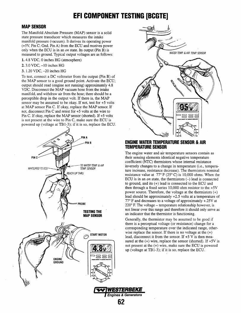
EFI COMPONENT TESTING [RCGTE] MAP SENSOR The Manifold Absolute Pressure (MAP) sensor is a solid state pressure transducer which measures the intake· manifold pressure (vacuum). It derives its operating power (+5V, Pin C; Gnd, Pin A) from the ECU and receives power only when the ECU is in an on state. Its output (Pin B) is measured to ground. Typical output voltages are as follows:
1.4.8 VDC, 0 inches HG (atmosphere)
2.3.0 VDC, -10 inches HG
3. 1.20 VDC, -20 inches HG
To test, connect a DC voltmeter from the output (Pin B) of the MAP sensor to a good ground point. Activate the ECU; output should read (engine not running) approximately 4.8 VDC. Disconnect the MAP vacuum hose from the intake manifold, and withdraw air from the hose; there should be a perceptible drop in the output volt. If there is, the MAP sensor may be assumed to be okay. If not, test for +5 volts at MAP sensor Pin C. If okay, replace the MAP sensor. If not, disconnect Pin C and retest for +5 volts at the wire to Pin C. If okay, replace the MAP sensor (shorted). If +5 volts is not present at the wire to Pin C, make sure the ECU is powered up (voltage at TBl-3); if it is so, replace the ECU.
PIN
PIN B
\.IJ..t/ftf,J.4r:--- TO WATER TEMP. & AIR TEMP. SENSOR
REACH UP THRU
TESTING THE MAP SENSOR
WATER TEMP. & AIR TEMP. SENSOR
ENGINE WATER TEMPERATURE SENSOR & AIR TEMPERATURE SENSOR The engine water and air temperature sensors contain as their sensing elements identical negative temperature coefficient (NTC) thermistors whose internal resistance inversely changes to a change in temperature (i.e., temperature increase, resistance decrease). The thermistors nominal resistance value at 770 F (25 0 C) is 10,000 ohms. When the ECU is in an on state, the thermistors (-) lead is connected to ground, and its (+) lead is connected to the ECU and then through a fixed series 10,000 ohm resistor to the +5V power source. Therefore, the voltage at the thermistors (+) lead should be approximately +2.5 volts at a temperature of 770 F and decreases to a voltage of approximately +.25V at 2200 F. The voltage - temperature relationship however, is not linear over this range and therefore it should only serve as an indicator that the thermistor is functioning.
Generally, the thermistor may be assumed to be good if there is a perceptual voltage (or resistance) change for a corresponding temperature over the indicated range, otherwise replace the sensor. If there is no voltage at the (+) lead, disconnect it from the sensor. If +5 V is then measured at the (+) wire, replace the sensor (shorted). If +5V is not present at the (+) wire, make sure the ECU is powered up (voltage at TB 1-3); if it is so·, replace the ECU.
Engines & Generators
62
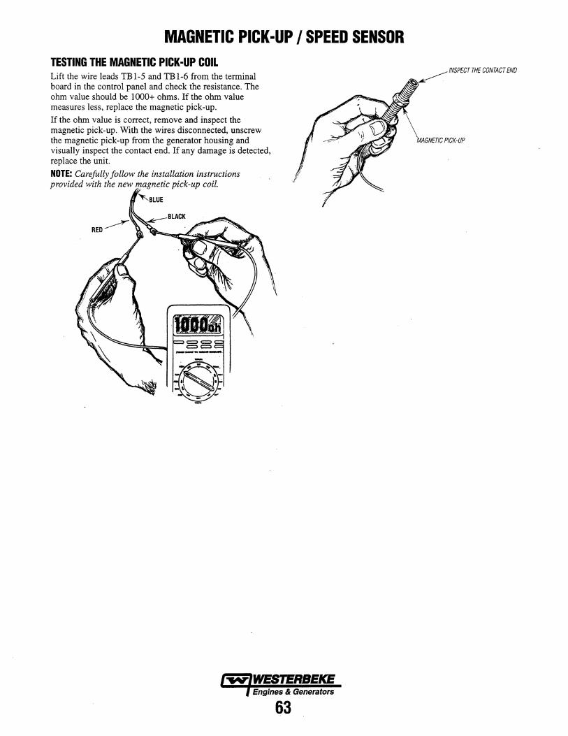
MAGNETIC PICK-UP I SPEED SENSOR TESTING THE MAGNETIC PICK-UP COIL Lift the wire leads TB 1-5 and TB 1-6 from the terminal board in the control panel and check the resistance. The ohm value should be 1000+ ohms. If the ohm value measures less, replace the magnetic pick-up.
If the ohm value is correct, remove and inspect the magnetic pick-up. With the wires disconnected, unscrew the magnetic pick-up from the generator housing and visually inspect the contact end. If any damage is detected, replace the unit.
NOTE: Carefully follow the installation instructions provided with the new pick-up coil.
Engines & Generators
63
INSPECT THE CONTACT END
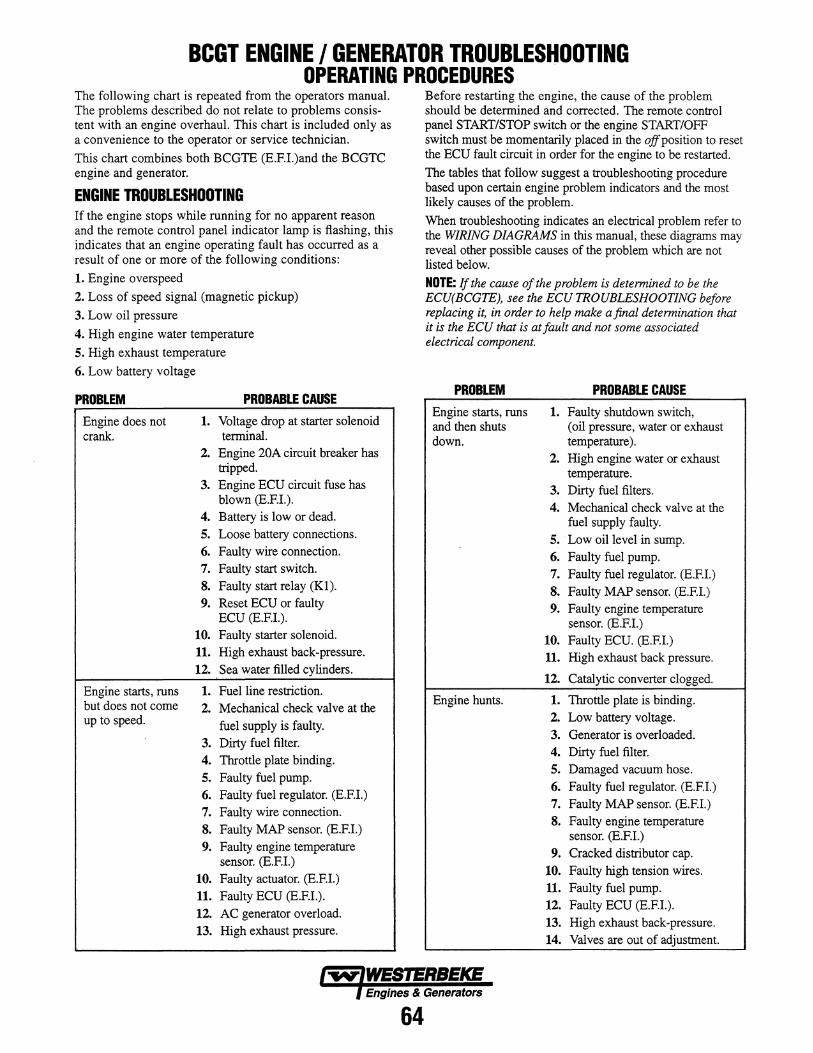
BeGT ENGINE I GENERATOR TROUBLESHOOTING OPERATING PROCEDURES .
The following chart is repeated from the operators manual. The problems described do not relate to problems consistent with an engine overhaul. This chart is included only as a convenience to the operator or service technician.
This chart combines both BCGTE (E.F.L)and the BCGTC engine and generator.
ENGINE TROUBLESHOOTING If the engine stops while running for no apparent reason and the remote control panel indicator lamp is flashing, this indicates that an engine operating fault has occurred as a result of one or more of the following conditions:
1. Engine overs peed
2. Loss of speed signal (magnetic pickup)
3. Low oil pressure
4. High engine water temperature
5. High exhaust temperature
6. Low battery voltage
PROBLEM
Engine does not crank.
Engine starts, runs but does not come up to speed.
PROBABLE CAUSE
1. Voltage drop at starter solenoid terminal.
2. Engine 20A circuit breaker has tripped.
3. Engine ECU circuit fuse has blown (E.F.I.).
4. Battery is low or dead.
5. Loose battery connections.
6. Faulty wire connection.
7. Faulty start switch.
S. Faulty start relay (Kl). 9. Reset ECU or faulty
ECU (E.F.I.). 10. Faulty starter solenoid. 11. High exhaust back-pressure.
12. Sea water filled cylinders.
1. Fuel line restriction. 2. Mechanical check valve at the
fuel supply is faulty. 3. Dirty fuel filter. 4. Throttle plate binding. 5. Faulty fuel pump. 6. Faulty fuel regulator. (E.F.I.) 7. Faulty wire connection.
S. Faulty MAP sensor. (E.F.I.) 9. Faulty engine temperature
sensor. (E.F.I.) 10. Faulty actuator. (E.EI.) 11. Faulty ECU (E.EL).
12. AC generator overload. 13. High exhaust pressure.
Before restarting the engine, the cause of the problem should be determined and corrected. The remote control panel START/STOP switch or the engine START/OFF switch must be momentarily placed in the ojfposition to reset the ECU fault circuit in order for the engine to be restarted.
The tables that follow suggest a troubleshooting procedure based upon certain engine problem indicators and the most likely causes of the problem.
When troubleshooting indicates an electrical problem refer to the WIRING DIAGRAMS in this manual, these diagrams may reveal other possible causes of the problem which are not listed below.
NOTE: If the cause of the problem is determined to be the ECU(BCGTE), see the ECU TROUBLESHOOTING before replacing it, in order to help make a final determination that it is the ECU that is at fault and not some associated electrical component.
PROBLEM
Engine starts, runs and then shuts down.
Engine hunts.
PROBABLE CAUSE
1. Faulty shutdown switch, (oil pressure, water or exhaust temperature).
2. High engine water or exhaust temperature.
3. Dirty fuel filters. 4. Mechanical check valve at the
fuel supply faulty.
5. Low oil level in sump.
6. Faulty fuel pump.
7. Faulty fuel regulator. (E.EI.)
S. Faulty MAP sensor. (E.EI.) 9. Faulty engine temperature
sensor. (E.F.I.) 10. Faulty ECU. (E.EI.) 11. High exhaust back pressure.
12. Catalytic converter clogged.
1. Throttle plate is binding. 2. Low battery voltage.
3. Generator is overloaded. 4. Dirty fuel filter.
5. Damaged vacuum hose. 6. Faulty fuel regulator. (E.EI.) 7. Faulty MAP sensor. (E.EI.) S. Faulty engine temperature
sensor. (E.F.L) 9. Cracked distributor cap.
10. Faulty high tension wires. 11. Faulty fuel pump. 12. Faulty ECU (E.EI.).
13. High exhaust back-pressure. 14. Valves are out of adjustment.
Engines & Generators
64
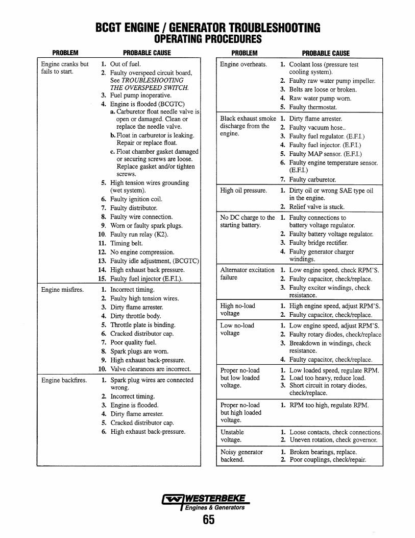
PROBLEM
Engine cranks but fails to start.
Engine misfires.
Engine backfires.
BCGT ENGINE I GENERATOR TROUBLESHOOTING OPERATING PROCEDURES
PROBABLE CAUSE PROBLEM PROBABLE CAUSE 1. Out of fuel. Engine overheats. 1. Coolant loss (pressure test 2. Faulty overspeed circuit board, cooling system).
See TROUBLESHOOTING 2. Faulty raw water pump impeller. THE OVERSPEED SWITCH. 3. Belts are loose or broken.
3. Fuel pump inoperative. 4. Engine is flooded (BCGTC)
a. Carburetor float needle valve is
4. Raw water pump worn. 5. Faulty thermostat.
open or damaged. Clean or Black exhaust smoke 1. Dirty flame arrester. replace the needle valve.
h. Float in carburetor is leaking.
discharge from the 2. Faulty vacuum hose .. engine. 3. Faulty fuel regulator. (E.EI.)
Repair or replace float. 4. Faulty fuel injector. (E.EI.) c. Float chamber gasket damaged
or securing screws are loose. Replace gasket and/or tighten screws.
5. Faulty MAP sensor. (E.EI.) 6. Faulty engine temperature sensor.
(E.EI.)
5. High tension wires grounding 7. Faulty carburetor.
(wet system). High oil pressure. 1. Dirty oil or wrong SAE type oil 6. Faulty ignition coil. in the engine.
7. Faulty distributor. 2. Relief valve is stuck.
s. Faulty wire connection. No DC charge to the 1. Faulty connections to 9. Worn or faulty spark plugs. starting battery. battery voltage regulator.
10. Faulty run relay (K2). 2. Faulty battery voltage regulator.
11. Timing belt. 3. Faulty bridge rectifier.
12. No engine compression. 4. Faulty generator charger
13. Faulty idle adjustment, (BCGTC) windings.
14. High exhaust back pressure. Alternator excitation 1. Low engine speed, check RPM'S. 15. Faulty fuel injector (E.EI.). failure 2. Faulty capacitor, check/replace.
1. Incorrect timing. 2. Faulty high tension wires.
3. Faulty exciter windings, check resistance.
3. Dirty flame arrester. 4. Dirty throttle body.
High no-load 1. High engine speed, adjust RPM'S. voltage 2. Faulty capacitor, check/replace.
5. Throttle plate is binding. Low no-load 1. Low engine speed, adjust RPM'S. 6. Cracked distributor cap. voltage 2. Faulty rotary diodes, check/replace 7. Poor quality fuel. 3. Breakdown in windings, check s. Spark plugs are worn. resistance.
9. High exhaust back-pressure. 4. Faulty capacitor, check/replace.
10. Valve clearances are incorrect. Proper no-load 1. Low loaded speed, regulate RPM.
1. Spark plug wires are connected wrong.
2. Incorrect timing.
but low loaded 2. Load too heavy, reduce load. voltage. 3. Short circuit in rotary diodes,
check/replace.
3. Engine is flooded. Proper no-load 1. RPM too high, regulate RPM. 4. Dirty flame arrester.
5. Cracked distributor cap.
but high loaded voltage.
6. High exhaust back-pressure. Unstable 1. Loose contacts, check connections. voltage. 2. Uneven rotation, check governor.
Noisy generator 1. Broken bearings, replace. backend. 2. Poor couplings, check/repair.
Engines & Generators
65
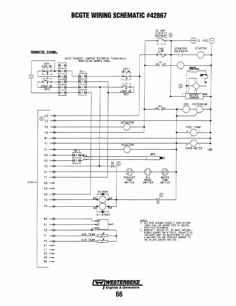
REMOTE PANE!...
@L3 L2
Y2
Y3
WI
YI
XI
X3
X2
T2
SI
TI
EC R3
P3
S2
T3
S3
W3
RI
R2
PI
P2 NI LI NZ N3 W2
BCGTE WIRING SCHEMATIC #42867
NOTE:REMOVE JUMPER BETWEEN TERMINALS WHEN US I NG REMOTE PANEL.
D2 ill
K I -START
MAP
CKTI .C[F -.s~
1_ ...J
EXHAUST TEMP
SWITCH
Engines & Generators
66
25 AMP CIRCUIT CD BREAKER I~ ...,
~--~ ~-4~----~~12 VDC
FUSE 2 AII~
STARTER SOLENOID
STARTER
COIL DISTRIBUTOR
MPU
OIL PRESS.
SWITCH
!!.Qill.:.
DI
WATER TEMP
SWITCH
FUEL PUMP +
+ HOUR METER
I. ALL WIRE tl6AWG(I050EG C 600V-ALPHAI 1858119-14 I L -'-168780 TYPE B I UNLESS SPEC IF I ED OTHERWI SE.
2. WARN I NG - RELAYS K I. K2 HAVE INTERNAL DIODES ACROSS THEIR COILS. POLARITY AS INDICATED MUST BE MAINTAINED TO AVOID A MALFUNCTION AND POSSIBLE DAMAGE TO THE RELAYS AND lOR THE ECU.
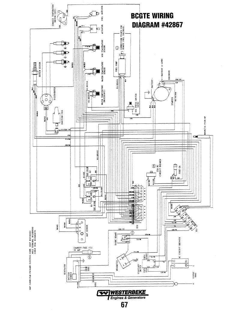
I
I I
~ ~
< ~
~
"
<
" ~
r-C~
4'''''''''' ".
01A11II
,
1
o '--
~ ~
~ ~= ](JII ~~
n iii -.z....r :"",
< ..
CHARGER fUSE (f1)
30AMP~
I ® rO;-H'
'--! 'd :"l
'-- ..: <9:: . ;;: -
I
I II
:~
== V~
:0
fA' 3~ \V V~
o
~ ;
I BeGTE WIRING
I DIAGRAM #42867
" v
V Q
>
+
I , ,
II ,
I
,,.
gl fEl * l i~== >l--I~'~llillot~~ Q
Engines & Generators
67
RI
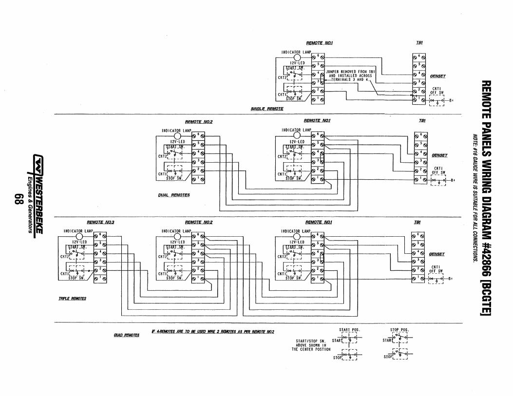
~ CQ :;-
c:nlll COSIo
~ :::J CD ~ o iil
flEMOTE NO.3
INDICATOR LAMP
TRIPLE REMOTES
QUAO REMOTES
flEMOTE N02
DUAL REM~
REMOTE NI12
INDICATOR LAMP
SINGLE REMOTE
~TES ARE ro BE USED WIRE 2 REMOTES AS PER REMOTE NO.2
flEMOTE NO.1
flEMOTE NO.'
REMOTE Nat
START POS. ,---, I I I
START/STOP SI'/. STA~ A80V£ SHOWN IN - r-
TH£ C£NT£R POSTION r-r-' ---lo<J.-J.-.o!
STOP~ * ~ L ___ J
S~O.!' _POS.
STARt"}+-i- J
r-r-' ST#"ir+-L ___ J
IJJI
~B'
IH1
~8'
IH1
8,
:1:1 m i: Q ... m ;g ~Z rrtm ;';'r~U)
~c::: ~c::; .,.,-:s:l:l ~Z (;) (l)C') s: ~5! ::;:;:x:-~C')
~~ ~i: ~=tI: iS~ ~N . CO
en en -a:I n C') ... m ......
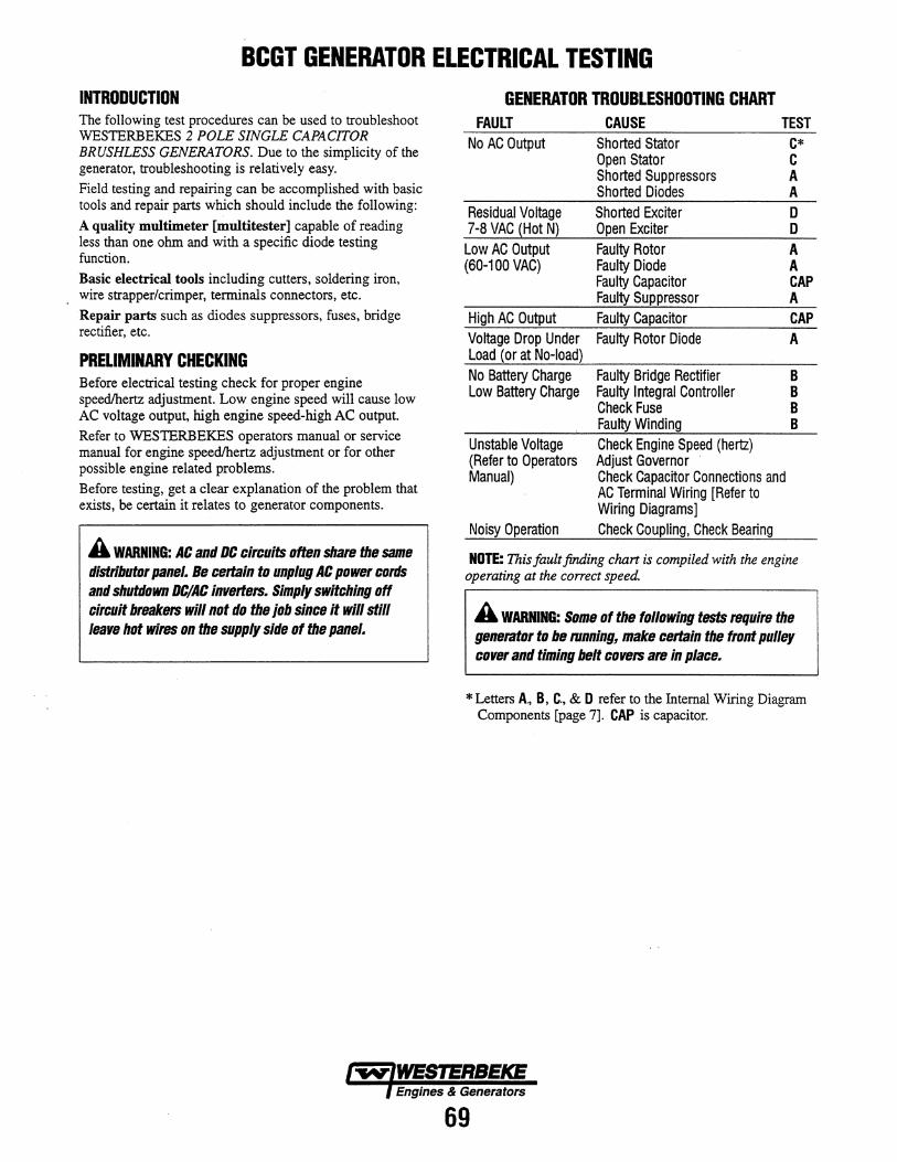
BCGT GENERATOR ELECTRICAL TESTING INTRODUCTION The following test procedures can be used to troubleshoot WESTERBEKES 2 POLE SINGLE CAPACITOR BRUSHLESS GENERATORS. Due to the simplicity of the generator, troubleshooting is relatively easy.
Field testing and repairing can be accomplished with basic tools and repair parts which should include the following:
A quality multimeter [multitester] capable of reading less than one ohm and with a specific diode testing function.
Basic electrical tools including cutters, soldering iron, wire strapper/crimper, terminals connectors, etc.
Repair parts such as diodes suppressors, fuses, bridge rectifier, etc.
PRELIMINARY CHECKING Before electrical testing check for proper engine speedlhertz adjustment. Low engine speed will cause low AC voltage output, high engine speed-high AC output.
Refer to WESTERBEKES operators manual or service manual for engine speedlhertz adjustment or for other possible engine related problems.
Before testing, get a clear explanation of the problem that exists, be certain it relates to generator components.
A WARNING: AC and DC circuits often share the same distributor panel. Be certain to unplug AC power cords and shutdown DC/AC inverters. Simply swftching off circuit breakers will not do the job since it will still leave hot wires on the supply side of the panel.
GENERATOR TROUBLESHOOTING CHART FAULT CAUSE TEST
No AC Output Shorted Stator C* Open Stator C Shorted Suppressors A Shorted Diodes A
Residual Voltage Shorted Exciter D 7-8 VAC {Hot N) Open Exciter D Low AC Output Faulty Rotor A (60-100 VAC) Faulty Diode A
Faulty CapaCitor CAP Faulty Suppressor A
High AC Output Faulty Capacitor CAP Voltage Drop Under Faulty Rotor Diode A Load {or at No-load) No Battery Charge Faulty Bridge Rectifier B Low Battery Charge Faulty Integral Controller B
Check Fuse B Faulty Winding B
Unstable Voltage Check Engine Speed (hertz) (Refer to Operators Adjust Governor Manual) Check Capacitor Connections and
AC Terminal Wiring [Refer to Wiring Diagrams]
Noisy Operation Check Coupling, Check Bearing
NOTE: This fault finding chczrt is compiled with the engine operating at the correct speed.
A WARNING: Some of the following tests require the generator to be mnning, make certain the front pulley cover and timing belt covers are in place.
* Letters A., B, C., & D refer to the Internal Wiring Diagram Components [page 7]. CAP is capacitor.
Engines & Generators
69
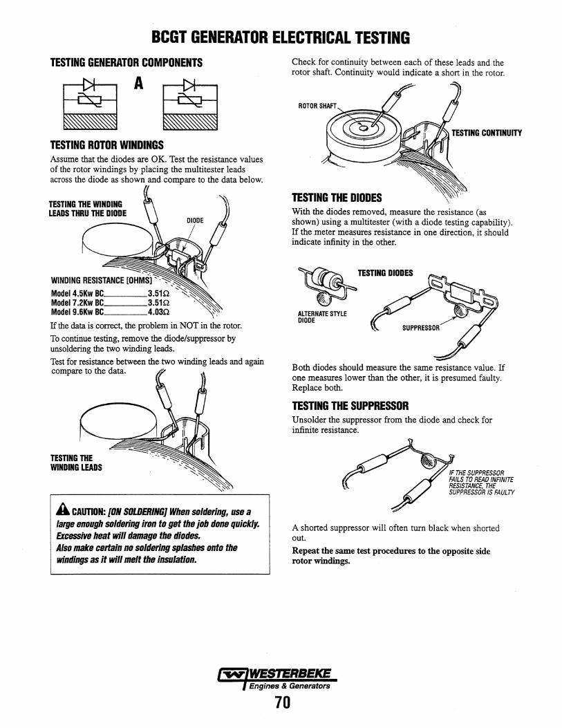
BCGT GENERATOR ELECTRICAL TESTING TESTING GENERATOR COMPONENTS
TESTING ROTOR WINDINGS Assume that the diodes are OK. Test the resistance values of the rotor windings by placing the multitester leads across the diode as shown and compare to the data below.
Model4.5Kw BC, ___ _ Model7.2Kw BC, ___ _ Model9.6Kw BC, ___ _
If the data is correct, the problem in NOT in the rotor.
To continue testing, remove the diode/suppressor by unsoldering the two winding leads.
Test for resistance between the two winding leads and again compare to the data~
TESTING THE MNDING LEADS
A CAUTION: [ON SOLDERING] When soldering, use a large enough soldering iron to get the job done quickly. Excessive heat will damage the diodes. Also make certain no soldering splashes onto the windings as it will melt the insulation.
Check for continuity between each of these leads and the rotor shaft. Continuity would inoicate a short in the rotor.
TESTING CONTINUITY
TESTING THE DIODES With the diodes removed, measure the resistance (as shown) using a multitester (with a diode testing capability). If the meter measures resistance in one direction, it should indicate infinity in the other.
~ TESnIIG DIIDES
ALTERNATE STYLE DIODE
Both diodes should measilre the same resistance value. If one measures lower than the other, it is presumed faulty. Replace both.
TESTING THE SUPPRESSOR Unsolder the suppressor from the diode and check for infinite resistance.
IF THE SUPPRESSOR FAILS TO READ INFINITE RESISTANCE. THE SUPPRESSOR IS FAULTY
A shorted suppressor will often turn black when shorted out.
Repeat the same test procedures to the opposite side rotor windings.
Engines & Generators
70
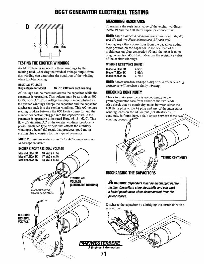
· SCGT GENERATOR ELECTRICAL TESTING
o
I-t-TESTING THE EXCITER WINDINGS An AC voltage is induced in these windings by the rotating field. Checking the residual voltage output from this winding can determine the condition of the winding when troubleshooting.
RESIDUAL VOLTAGE Single Capacitor Model 16 -18 VAC from each winding
AC voltage can be measured across the capacitor while the generator is operating. This voltage may be as high as 400 to 500 volts AC. This voltage buildup is accomplished as the exciter windings charge the capacitor and the capacitor discharges back into the exciter windings. This AC voltage reading is taken between the #60 Hertz connector and the number connection plugged into the capacitor while the generator is operating at its rated Hertz (61.5 - 62.0). This flow of saturating AC in the exciter windings produces a phase-imbalance type of field that effects the auxillary windings: a beneficial result that produces good motor starting characteristics for this type of generator.
NOTE: Position the meter correctly for AC voltage so as not to damage the meter.
EXCITER CIRCUIT RESIDUAL VOLTAGE
Model4.5Kw BC 16 VAC (± .5) Model 7.2Kw BC 17 VAC (± .5) Model 9.6Kw BC' 18 VAC (± .5)
CHECKING RESIDUAL VOLTAGE
TESTING AC VOLTAGE [GENERATOR RUNNING]
MEASURING RESISTANCE To measure the resistance value of the exciter windings, locate #9 and the #50 Hertz capacitor connections.
NOTE: Three numbered capacitor connections exist: #7, #8, and #9; and two Hertz connections, #50 and #60.
Unplug any other connections from the capacitor noting their position on the capacitor. Place one lead of the multimeter on plug connection #9 and the other lead on plug, connection #50 Hertz. Measure the resistance value of the exciter windings.
WINDING RESISTANCE [OHMS]
Model 4.5Kw BC 4.550 Model7.2Kw BC 3.960 Model9.6Kw BC 3.710
NOTE: Lower residual voltage along with a lower winding resistance will confirm a faulty winding.
CHECKING CONTINUITY Check to make sure there is no continuity to the ground/generator case from either of the two leads. Also check that no continuity exists between either the #60 Hertz plug or the #8 plug and any of the main stator winding leads on the AC output (not illustrated). If continuity is found he~e, a fault exists between thes~ two ..... ~ winding groups. ~ ~
TESTING CONTINUITY
....
A CAUTION: Capacitors must be discharged before testing. CapaCitors store electricity and can pack a lethal punch even when disconnected from the power source.
Discharge the capacitor by a bridging the terminals with a screwdriver.
Engines & Generators
71
"
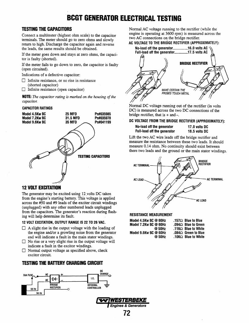
· BCGT GENERATOR ELECTRICAL TESTING TESTING THE CAPACITORS Connect a multitester (highest ohm scale) to the capacitor terminals. The meter should go to zero ohms and slowly return to high. Discharge the capacitor again and reverse the leads, the same results should be obtained.
If the meter goes down and stays at zero ohms, the capacitor is faulty (shorted).
If the meter fails to go down to zero, the capacitor is faulty (open circuited).
Indications of a defective capacitor:
o Infinite resistance, or no rise in resistance (shorted capacitor)
o Infinite resistance (open capacitor)
NOTE: The capacitor rating is marked on the housing of the capacitor.
CAPACITOR RATINGS
Model 4.5Kw BC Model 7.2Kw BC Model 9.6Kw BC
12 VOLT EXCITATION
25MFD 31.5 MFD 35 MFD
Pn#035985 Pn#035978 Pn#041199
TESTING CAPACITORS
The generator may be excited using 12 volts DC taken from the engine's starting battery. This voltage is applied across the #50 and #9 leads of the exciter circuit windings (unplugged) with any other numbered leads unplugged from the capacitors. The generator's reaction during flashing will help determine its fault.
12 VOLT EXCITATION, OUTPUT RANGE IS 22 TO 26 VAC.
o A slight rise in the output voltage with the loading of the engine and/or a growling noise from the generator end will indicate a fault in the main stator windings.
o No rise or a very slight rise in the output voltage will indicate a fault in the excitor windings.
o Normal output voltage as specified above, check excitor circuit.
TESTING THE BArrERY CHARGING CIRCUIT
Normal AC voltage running to the rectifier (while the engine is operating at 3600 rpm) is measured across the two AC connections o~ the bridge rectifier. AC VOLTAGE TO THE BRIDGE RECTIFIER (APPROXIMATELY):
No-load off the generator __ _ Full-load off the generator __ _
BRIDGE RECTIFIER
MAKE CERTAIN THE PROBES TOUCH METAL
Normal DC voltage running out of the rectifier (in volts DC) is measured across the two DC connections of the bridge rectifier, that is + and-.
DC VOLTAGE FROM THE BRIDGE RECTIFIER (APPROXIMATELY):
No-load off the generator 17.0 volts DC Full-load off the generator 18.5 volts DC
Lift the two AC wire leads off the bridge rectifier and measure the resistance between these two leads. It should measure 0.14 ohm. No continuity should exist between there two leads and the ground or the main stator windings.
AC LEAD
RESISTANCE MEASUREMENT
Model 4.5Kw BC @ 60Hz Model 7.2Kw BC @ 60Hz
@50Hz Model 9.6Kw BC @ 60Hz
@50Hz
.1570. Blue to Blue
.094n Blue to Green
.116n Blue to White
.084n Green tD Blue
.106n Blue to White
ACTERMINAL
Engines & Generators
72
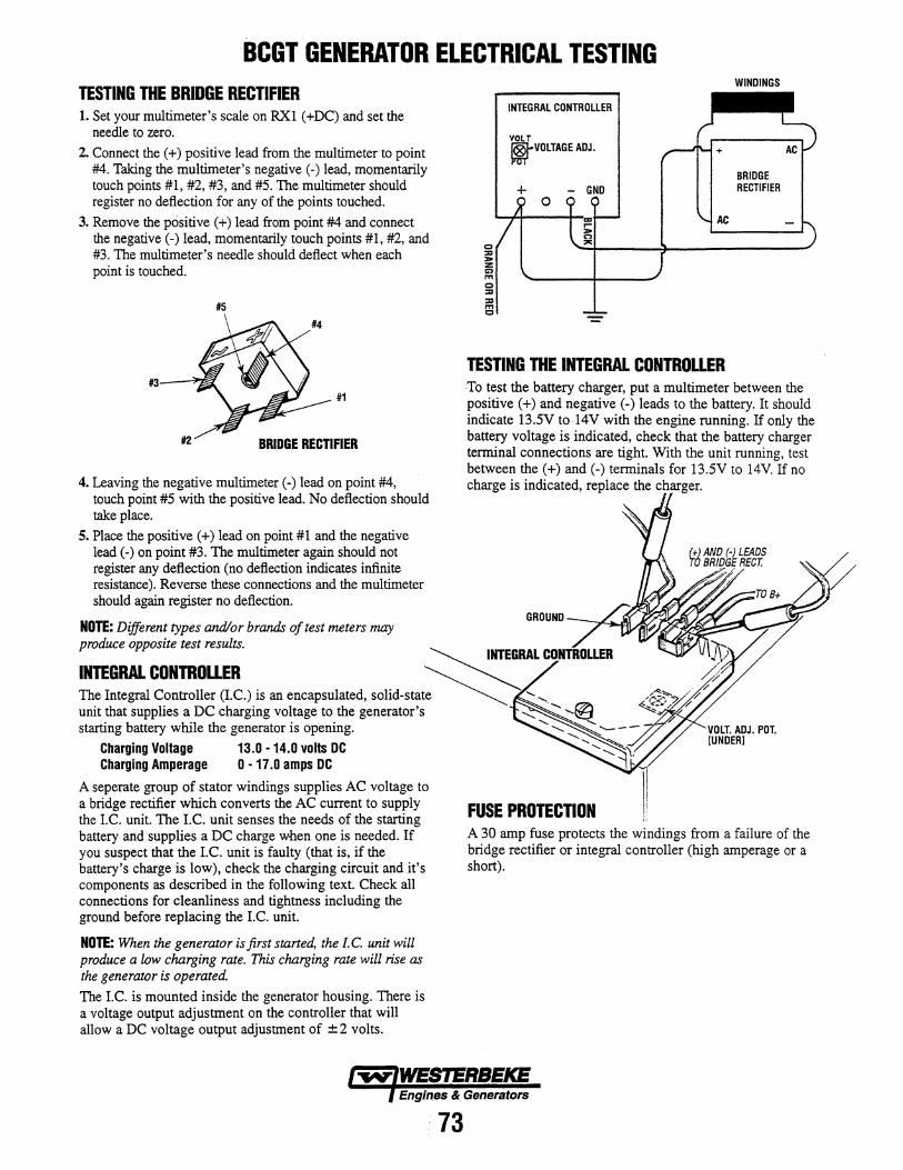
BCGT GENERATOR ELECTRICAL TESTING TESTING THE BRIDGE RECTIFIER 1. Set your multimeter's scale on RX1 (+DC) and set the
needle to zero.
2. Connect the (+) positive lead from the multimeter to point #4. Taking the multimeter's negative (-) lead, momentarily touch points #1, #2, #3, and #5. The multimeter should register no deflection for any of the points touched.
3. Remove the positive (+) lead from point #4 and connect the negative (-) lead, momentarily touch points #1, #2, and #3. The multimeter's needle should deflect when each point is touched.
#5
#4
#3--"'et #1
#2 BRIDGE RECTIFIER
4. Leaving the negative multimeter (-) lead on point #4, touch point #5 with the positive lead. No deflection should take place.
5. Place the positive (+) lead on point #1 and the negative lead (-) on point #3. The multimeter again should not register any deflection (no deflection indicates infinite resistance). Reverse these connections and the multimeter should again register no deflection.
NOTE: Different types and/or brands o/test meters may
o :::a > z C) ."
o :::a :::a ." c
INTEGRAL CONTROLLER
VOLT ~VOLTAGE ADJ.
+ - GND
AC
TESTING THE INTEGRAL CONTROLLER
WINDINGS
BRIDGE RECTIFIER
To test the battery charger, put a multimeter between the positive (+) and negative (-) leads to the battery. It should indicate 13.5V to 14V with the engine running. If only the battery voltage is indicated, check that the battery charger terminal connections are tight. With the unit running, test between the (+) and (-) terminals for 13.5V to 14V If no charge is indicated, replace the charger.
GROUND
produce opposite test results. ~ INTEGRAL CONTROLLER
INTEGRAL CONTROLLER ~ ~ The Integral Controller (I.C.) is an encapsulated, solid-state ~ ...... ...... unit that supplies a DC charging voltage to the generator's ......... ...... ...... @ starting battery while the generator is opening. .............. ~ --- - - --......
Charging Voltage 13.0 -14.0 volts DC '- ...... ~:'I. Charging Amperage 0 • 17.0 amps DC
A seperate group of stator windings supplies AC voltage to a bridge rectifier which converts the AC current to supply the I.C. unit. The I.C. unit senses the needs of the starting battery and supplies a DC charge when one is needed. If you suspect that the I.e. unit is faulty (that is, if the battery's charge is low), check the charging circuit and it's components as described in the following text. Check all connections for cleanliness and tightness including the ground before replacing the I.C. unit.
NOTE: When the generator is first started, the I. C. unit will produce a low charging rate. This charging rate will rise as the generator is operated. The I.e. is mounted inside the generator housing. There is a voltage output adjustment on the controller that will allow a DC voltage output adjustment of ± 2 volts.
FUSE PROTECTION A 30 amp fuse protects the windings from a failure of the bridge rectifier or integral controller (high amperage or a short).
Engines & Generators
73
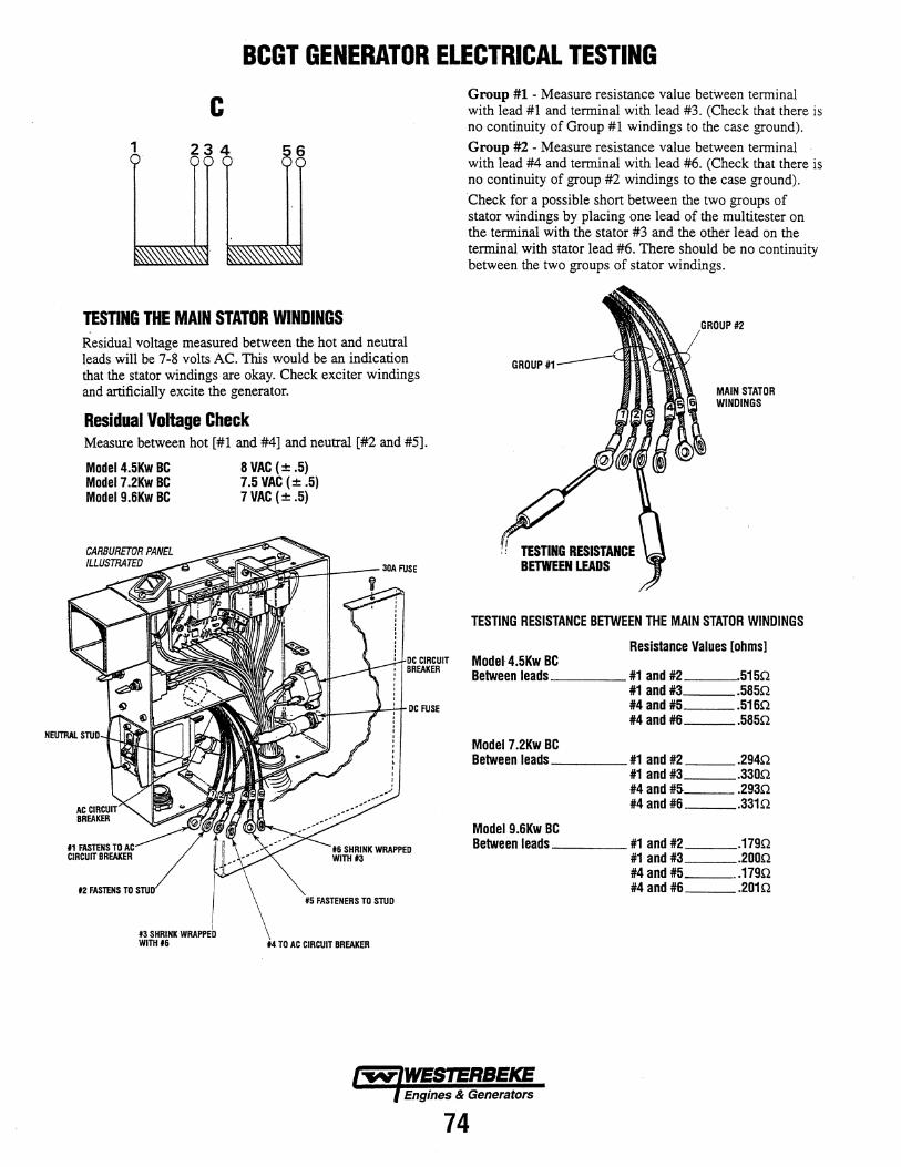
BCGT GENERATOR ELECTRICAL TESTING
C
TESTING THE MAIN STATOR WINDINGS Residual voltage measured between the hot and neutral leads will be 7-8 volts AC. This would be an indication that the stator windings are okay. Check exciter windings and artificially excite the generator.
Residual Voltage Check Measure between hot [#1 and #4] and neutral [#2 and #5].
Model 4.5Kw BC 8 VAC (± .5) Model 7.2Kw BC 7.5 VAC (± .5) Model9.6Kw BC 7 VAC (± .5)
t2 FASlENS TO #5 FASTENERS TO STUD
TO AC CIRCUIT BREAKER
Group #1 - Measure resistance value between terminal with lead #1 and terminal with lead #3. (Check that there is no continuity of Group #1 windings to the case ground).
Group #2 - Measure resistance value between terminal with lead #4 and terminal with lead #6. (Check that there is no continuity of group #2 windings to the case ground).
Check for a possible short between the two groups of stator windings by placing one lead of the multitester on the terminal with the stator #3 and the other lead on the terminal with stator lead #6. There should be no continuity between the two groups of stator windings.
GROUP #1
TESTING RESISTANCE BETWEEN LEADS
#2
MAIN STATOR WINDINGS
TESTING RESISTANCE BETWEEN THE MAIN STATOR WINDINGS
Resistance Values [ohms] Model· 4.5Kw BC Between leads ___ _ #1 and #2 5150
#1 and #3 .5850 #4 and #5 .5160 #4 and #6 .5850
Model 7.2Kw BC Between leads ___ _ #1 and #2 .2940
#1 and #3 .3300 #4 and #S .2930 #4 and #6 .3310
Model 9.6Kw BC Between leads ___ _ #1 and #2 .1790
#1 and #3 .2000 #4 and #5 .. 1790 #4 and #6 .2010
Engines & Generators
74
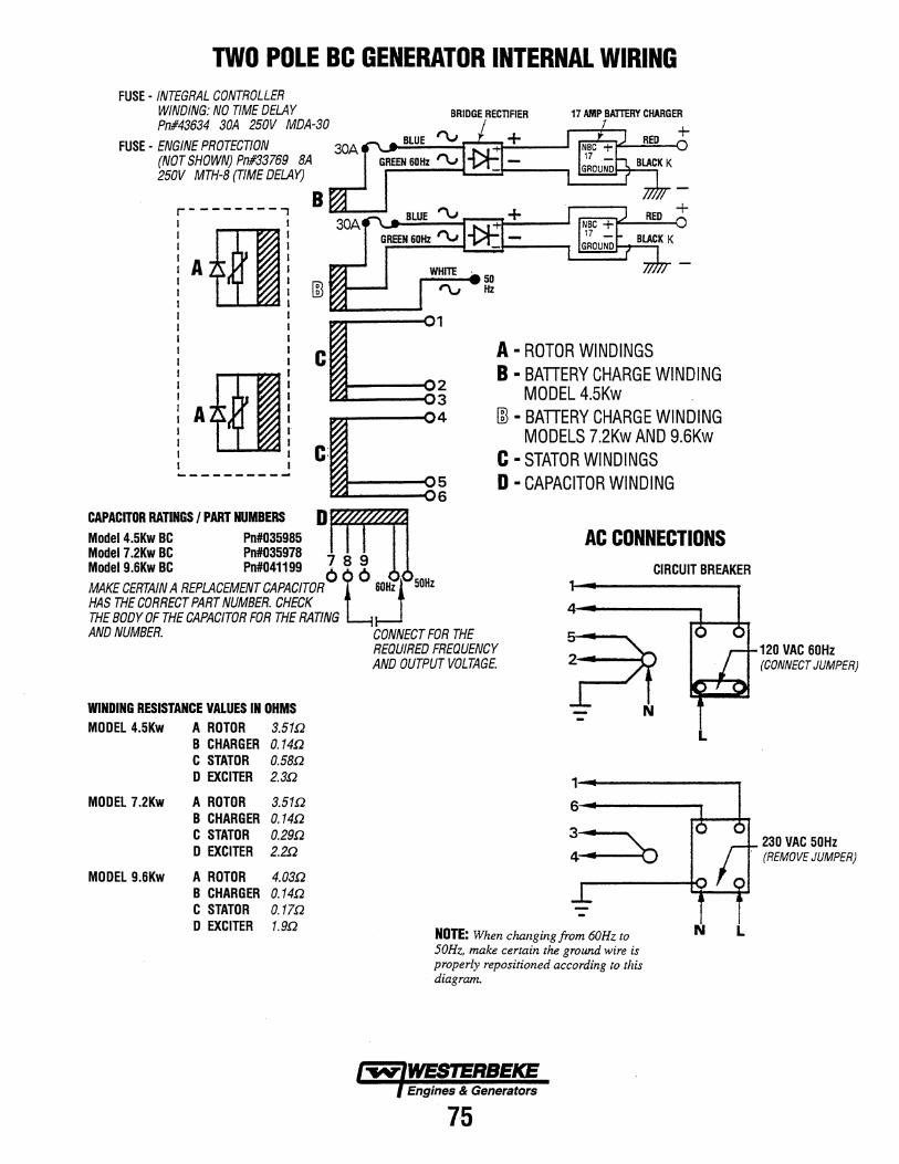
TWO POLE Be GENERATOR INTERNAL WIRING FUSE· INTEGRAL CONTROLLER
WINDING: NO TIME DELAY pn#43634 30A 250V MDA·30
FUSE· ENGINE PROTECTION 30A (NOT SHOWN) Pn#33769 8A 250V MTH·8 (TIME DELAY)
B ~-....I r--------, : fH: I I
: A : I I I I I I
Model 4.5Kw BC Po#035985
BRIDGE RECTIFIER
A • ROTOR WINDINGS B • BATTERY CHARGE WINDING
MODEL 4.SKw rn • BATTERY CHARGE WINDING
MODELS 7.2Kw AND 9.6Kw C • STATOR WINDINGS D • CAPACITOR WINDING
AC CONNECTIONS CAPACITOR RATINGS I PART NUMBERS D rrrn Model 7.2Kw BC Po#035978 7 8 9 Model 9.6Kw BC Po#041199 6· 6 MAKE CERTAIN A REPLACEMENT CAPACITOR t~ r~ HAS THE CORRECT PART NUMBER. CHECK
CIRCUIT BREAKER
THE BODY OF THE CAPACITOR FOR THE RATING AND NUMBER. CONNECT FOR THE
REQUIRED FREQUENCY AND OUTPUT VOLTAGE
WINDING RESISTANCE VALUES IN OHMS MODEL 4.5Kw A ROTOR 3.51!2
B CHARGER O.14!J C STATOR O.58!J
4~-------,
:?t - N
L
D EXCITER
MODEL 7.2Kw A ROTOR
2.3!J
3.51!2 1-.------~
6,~----..., B CHARGER O.14!J C STATOR O.29!J D EXCITER 2.2!J
MODEL 9.6Kw A ROTOR 4.03!J B CHARGER O.14!J C STATOR O.17!J D EXCITER 1.9!J
NOTE: When c/u;znging from 60Hz to 50Hz. make certain the ground wire is properly repositioned according to this diagram.
Engines & Generators
7-5
N L
120 VAC 60Hz (CONNECT JUMPER)
230 VAC 50Hz (REMOVE JUMPER)
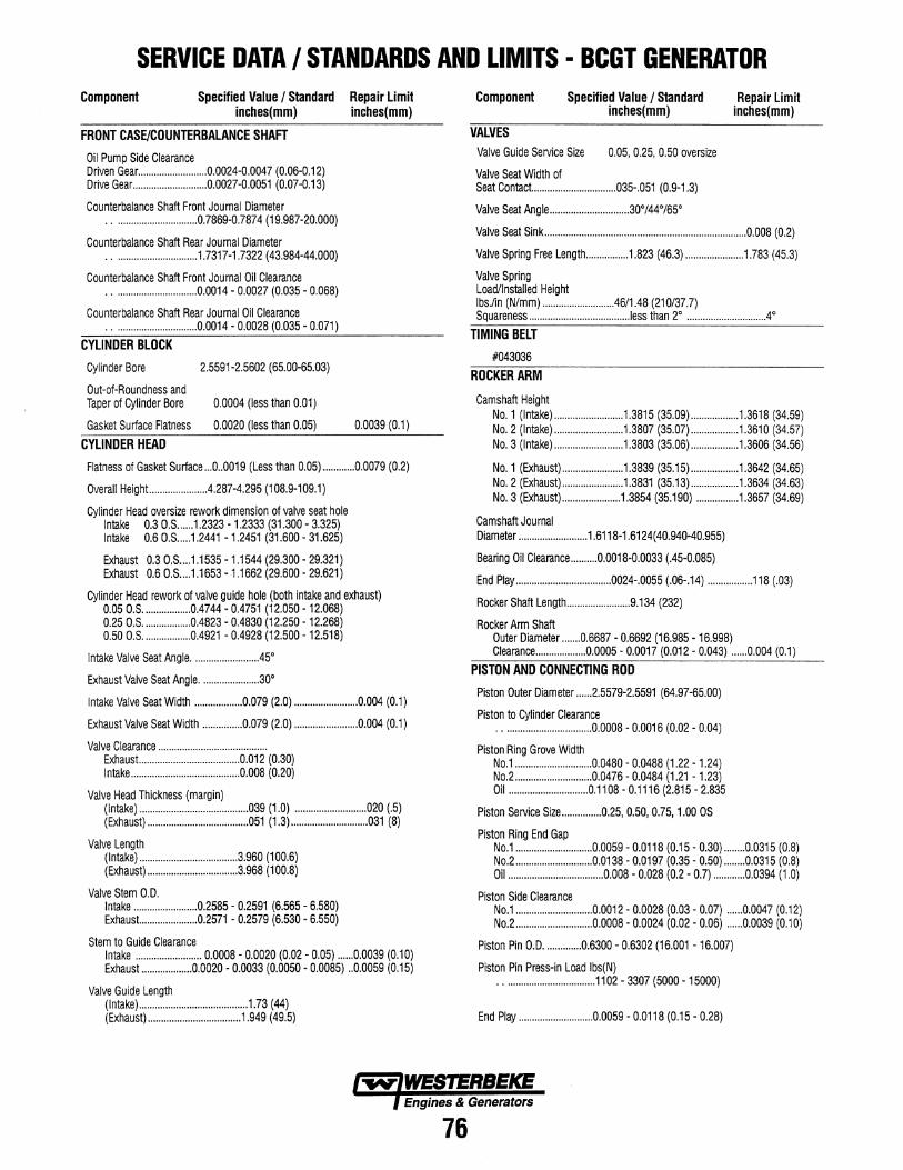
SERVICE DATA I STANDARDS AND LIMITS • BCGT GENERATOR Component Specified Value / Standard Repair Limit
inches(mm) inches(mm)
FRONT CASE/COUNTERBALANCE SHAFT
Oil Pump Side Clearance Driven Gear .......................... 0.0024-0.0047 (0.06-0.12) Drive Gear ............................ 0.0027-0.0051 (0.07-0.13)
Counterbalance Shaft Front Joumal Diameter · . . ............................. 0.7869-0.7874 (19.987-20.000)
Counterbalance Shaft Rear Journal Diameter ................................ 1.7317-1.7322 (43.984-44.000)
Counterbalance Shaft Front Journal Oil Clearance · ............................... 0.0014 - 0.0027 (0.035 - 0.068)
Counterbalance Shaft Rear Journal Oil Clearance · ............................... 0.0014 - 0.0028 (0.035 - 0.071)
CYLINDER BLOCK
Cylinder Bore 2.5591-2.5602 (65.00-65.03)
Out-of-Roundness and Taper of Cylinder Bore 0.0004 (less than 0.01)
Gasket Surface Flatness 0.0020 (less than 0.05)
CYLINDER HEAD 0.0039 (0.1)
Flatness of Gasket Surface ... 0 .. 0019 (Less than 0.05) ............ 0.0079 (0.2)
Overall HeighL. .................. .4.287-4.295 (108.9-109.1)
Cylinder Head oversize rework dimension of valve seat hole Intake 0.3 0.S ...... 1.2323 -1.2333 (31.300 - 3.325) Intake 0.6 0.S ..... 1.2441 -1.2451 (31.600 - 31.625)
Exhaust 0.3 O.S .... 1.1535 - 1.1544 (29.300 - 29.321) Exhaust 0.6 O.S .... 1.1653 - 1.1662 (29.600 - 29.621)
Cylinder Head rework of valve guide hole (both intake and exhaust) 0.05 O.S .................. 0.4744 - 0.4751 (12.050 -12.068) 0.25 O.S .................. 0.4823 - 0.4830 (12.250 -12.268) 0.50 O.S .................. 0.4921 - 0.4928 (12.500 -12.518)
Intake Valve Seat Angle ........................ .45·
Exhaust Valve Seat Angle ...................... 30·
Intake Valve Seat Width .................. 0.079 (2.0) ........................ 0.004 (0.1)
Exhaust Valve Seat Width ............... 0.079 (2.0) ........................ 0.004 (0.1)
Valve Clearance ........................................ . Exhaust... ................................... 0.D12 (0.30) Intake ......................................... 0.008 (0.20)
Valve Head Thickness (margin) (Intake) ......................................... 039 (1.0) ........................... 020 (.5) (Exhaust) ...................................... 051 (1.3) ............................. 031 (8)
Valve Length (Intake) ..................................... 3.960 (100.6) (Exhaust) .................................. 3.968 (100.8)
Valve Stem O.D. Intake ........................ 0.2585 - 0.2591 (6.565 - 6.580) Exhaust... ................... 0.2571 - 0.2579 (6.530 - 6.550)
Stem to Guide Clearance Intake ......................... 0.0008 - 0.0020 (0.02 - 0.05) ...... 0.0039 (0.10) Exhaust ................... 0.0020 - 0.0033 (0.0050 - 0.0085) .. 0.0059 (0.15)
Valve Guide Length (Intake) ......................................... 1.73 (44) (Exhaust) ................................... 1.949 (49.5)
Component
VALVES
Specified Value / Standard inches(mm)
Valve Guide Service Size 0.05, 0.25, 0.50 oversize
Valve Seat Width of Seat Contact ................................ 035-.051 (0.9-1.3)
Valve Seat Angle .............................. 30·/44·/65·
Repair Limit inches(mm)
Valve Seat Sink ............................................................................ 0.008 (0.2)
Valve Spring Free Length ................ 1.823 (46.3) ...................... 1.783 (45.3)
Valve Spring Load/Installed Height Ibs.lin (N/mm) .......................... .46/1.48 (210137.7) Squareness ..................................... .Iess than 2· ............................. .4.
TIMING BELT
#043036
ROCKER ARM
Camshaft Height No.1 (Intake) .......................... 1.3815 (35.09) .................. 1.3618 (34.59) No.2 (Intake) .......................... 1.3807 (35.07) .................. 1.3610 (34.57) No.3 (Intake) .......................... 1.3803 (35.06) .................. 1.3606 (34.56)
No.1 (Exhaust) ....................... 1.3839 (35.15) .................. 1.3642 (34.65) No.2 (Exhaust) ....................... 1.3831 (35.13) .................. 1.3634 (34.63) No.3 (Exhaust) ...................... 1.3854 (35.190) ................ 1.3657 (34.69)
Camshaft Journal Diameter .......................... 1.6118-1.6124( 40.940-40.955)
Bearing Oil Clearance .......... 0.0018-0.0033 (.45-0.085)
End Play .................................... 0024-.0055 (.06-.14) ................. 118 (.03)
Rocker Shaft Length ........................ 9.134 (232)
Rocker Arm Shaft Outer Diameter ....... 0.6687 - 0.6692 (16.985 - 16.998) Clearance ................... 0.0005 - 0.0017 (0.012 - 0.043) ...... 0.004 (0.1)
PISTON AND CONNECTING ROD
Piston Outer Diameter ...... 2.5579-2.5591 (64.97-65.00)
Piston to Cylinder Clearance .................................. 0.0008 - 0.0016 (0.02 - 0.04)
Piston Ring Grove Width No.1 ............................. 0.0480 - 0.0488 (1.22 - 1.24) No.2 ............................. 0.0476 - 0.0484 (1.21 - 1.23) Oil .............................. 0.1108 - 0.1116 (2.815 - 2.835
Piston Service Size ............... 0.25, 0.50, 0.75, 1.00 OS
Piston Ring End Gap No.1 ............................. 0.0059 - 0.0118 (0.15 - 0.30) ........ 0.0315 (0.8) No.2 ............................. 0.0138 - 0.0197 (0.35 - 0.50) ........ 0.0315 (0.8) Oil .................................... 0.008 - 0.028 (0.2 - 0.7) ............ 0.0394 (1.0)
Piston Side Clearance No.1 ............................. 0.0012 - 0.0028 (0.03 - 0.07) ...... 0.0047 (0.12) No.2 ............................. 0.0008 - 0.0024 (0.02 - 0.06) ...... 0.0039 (0.10)
Piston Pin O.D .............. 0.6300 - 0.6302 (16.001 -16.007)
Piston Pin Press-in Load Ibs(N) ................................... 1102 - 3307 (5000 -15000)
End Play ............................ 0.0059 - 0.0118 (0.15 - 0.28)
Engines & Generators
76
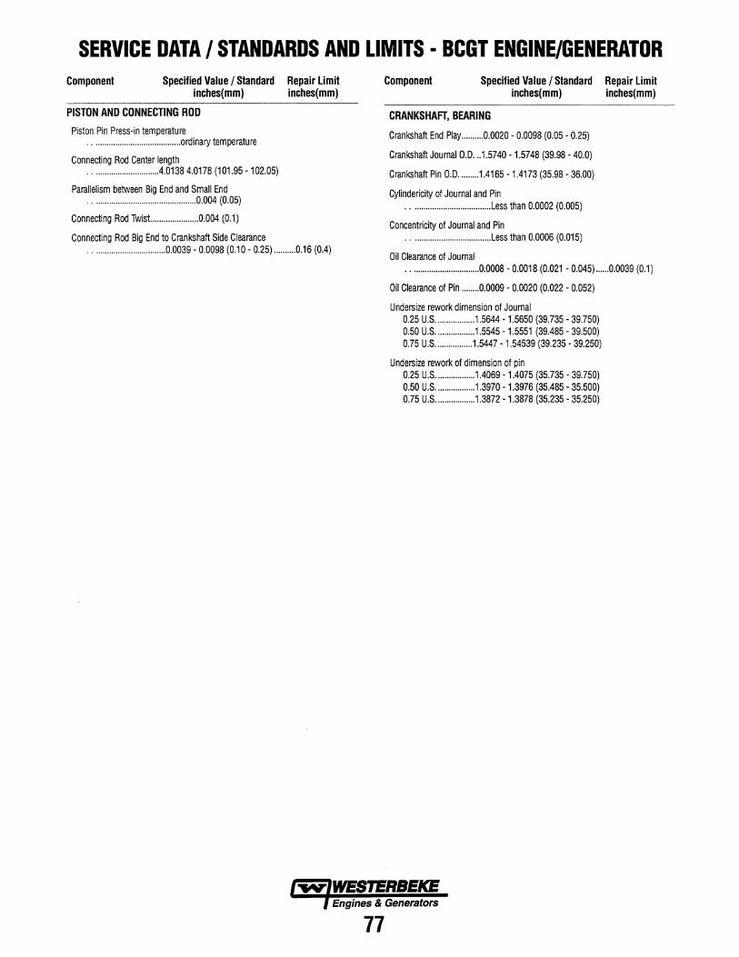
SERVICE DATA / STANDARDS AND LIMITS • BCGT ENGINE/GENERATOR Component Specified Value / Standard Repair limit
inches(mm) inches(mm)
PISTON AND CONNECTING ROD
Piston Pin Press-in temperature · ........................................ ordinary temperature
Connecting Rod Center length · ............................. .4.01384.0178 (101.95 -102.05)
Parallelism between Big End and Small End · ............................................... 0.004 (0.05)
Connecting Rod Twist.. .................... 0.004 (0.1)
Connecting Rod Big End to Crankshaft Side Clearance .................................. 0.0039 - 0.0098 (0.10 - 0.25) .......... 0.16 (0.4)
Component Specified Value / Standard Repair limit inches(mm) inches(mm)
CRANKSHAFT, BEARING
Crankshaft End Play .......... 0.0020 - 0.0098 (0.05 - 0.25)
Crankshaft Journal 0.0 ... 1.5740 -1.5748 (39.98 - 40.0)
Crankshaft Pin 0.0 ......... 1.4165 -1.4173 (35.98 - 36.00)
Cylindericity of Journal and Pin · ................................... .Less than 0.0002 (0.005)
Concentricity of Journal and Pin · .................................... Less than 0.0006 (0.015)
Oil Clearance of Journal · ............................... 0.0008 - 0.0018 (0.021 - 0.045) ...... 0.0039 (0.1)
Oil Clearance of Pin ........ 0.0009 - 0.0020 (0.022 - 0.052)
Undersize rework dimension of Journal 0.25 U.S .................. 1.5644 -1.5650 (39.735 - 39.750) 0.50 U.S .................. 1.5545 - 1.5551 (39.485 - 39.500) 0.75 U.S ................. 1.5447 -1.54539 (39.235 - 39.250)
Undersize rework of dimension of pin 0.25 U.S .................. 1.4069 - 1.4075 (35.735 - 39.750) 0.50 U.S .................. 1.3970 - 1.3976 (35.485 - 35.500) 0.75 U.S .................. 1.3872 - 1.3878 (35.235 - 35.250)
Engines & Generators
77
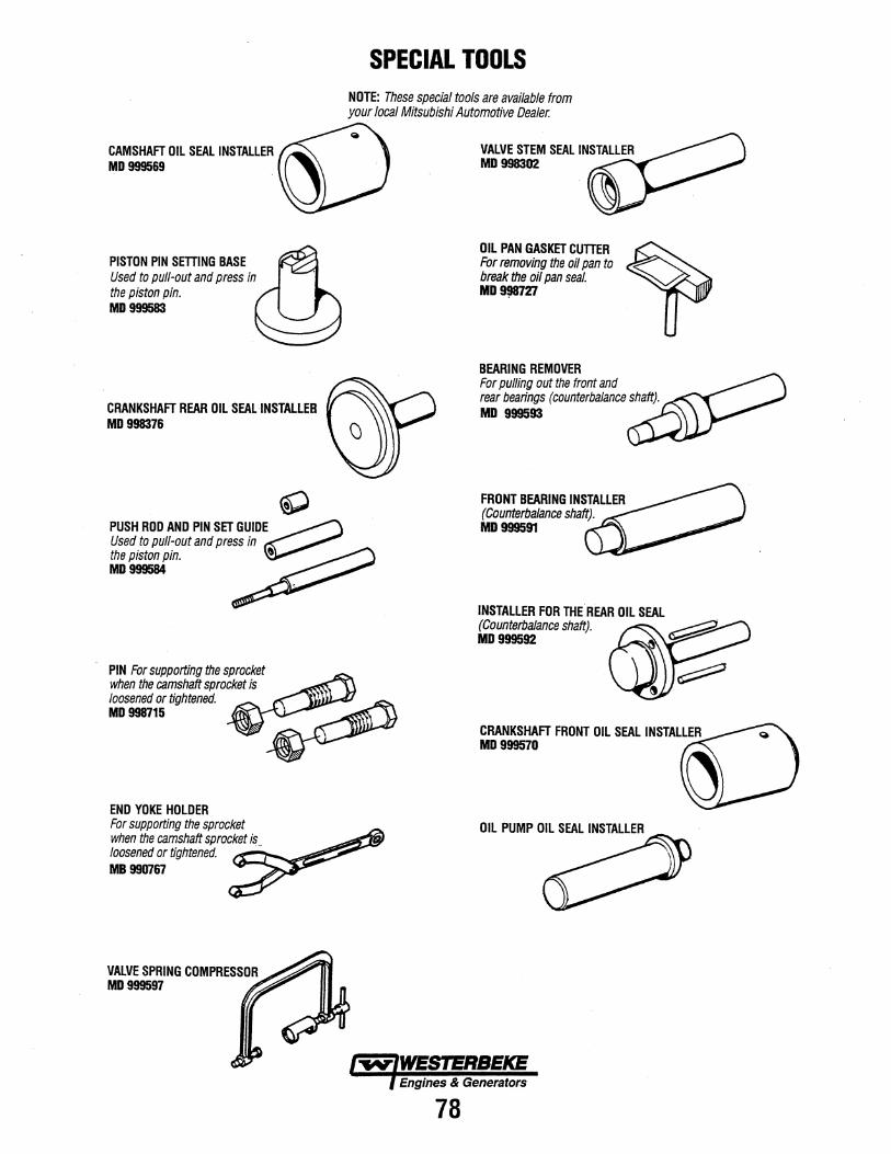
CAMSHAFT OIL SEAL INSTALLER MD 999569
PISTON PIN SETTING BASE Used to pull-out and press in the piston pin. MD 999583
CRANKSHAFT REAR OIL SEALINSTALLEB MD 998376
PIN For supporting the sprocket when the camshaft sprocket is loosened or tightened. MD 998715
END YOKE HOLDER For supporting the sprocket when the camshaft sprocket is_ loosened or tightened. MB 990767
SPECIAL TOOLS NOTE: These special tools are available from your local Mitsubishi Automotive Dealer.
OIL PAN GASKET CUTTER For removing the oil pan to break the oil pan seal. MD~27
BEARING REMOVER For pulling out the front and rear bearings (counterbalance shaft). MD 999593
FRONT BEARING INSTALLER (Counterbalance shaft). MD999591
CRANKSHAFT FRONT OIL SEAL INSTALLER MD999570
OIL PUMP OIL SEAL INSTALLER
Engines & Generators
78
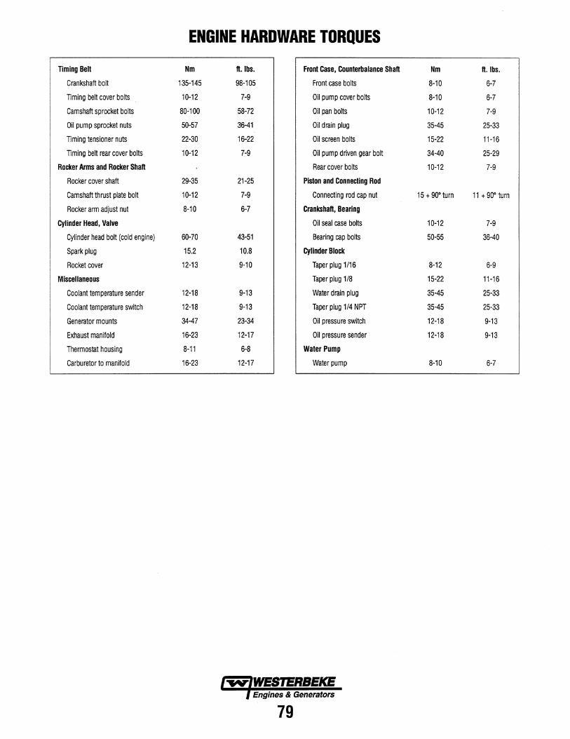
ENGINE HARDWARE TORQUES
Timing Belt Nm ft.lbs. Front Case, Counterbalance Shaft Nm ft. Ibs.
Crankshaft bolt 135-145 98-105 Front case bolts 8-10 6-7
TIming belt cover bolts 10-12 7-9 Oil pump cover bolts 8-10 6-7
Camshaft sprocket bolts 80-100 58-72 Oil pan bolts 10-12 7-9
Oil pump sprocket nuts 50-57 36-41 Oil drain plug 35-45 25-33
TIming tensioner nuts 22-30 16-22 Oil screen bolts 15-22 11-16
TIming belt rear cover bolts 10-12 7-9 Oil pump driven gear bolt 34-40 25-29
Rocker Arms and Rocker Shaft Rear cover bolts 10-12 7-9
Rocker cover shaft 29-35 21-25 Piston and Connecting Rod
Camshaft thrust plate bolt 10-12 7-9 Connecting rod cap nut 15 + 90" turn 11 + 90· turn
Rocker arm adjust nut 8-10 6-7 Crankshaft, Bearing
Cylinder Head, Valve Oil seal case bolts 10-12 7-9
Cylinder head bolt (cold engine) 60-70 43-51 Bearing cap bolts 50-55 36-40
Spark plug 15.2 10.8 Cylinder Block
Rocket cover 12-13 9-10 Taper plug 1/16 8-12 6-9
Miscellaneous Taper plug 1/8 15-22 11-16
Coolant temperature sender 12-18 9-13 Water drain plug 35-45 25·33
Coolant temperature switch 12-18 9-13 Taper plug 1/4 NPT 35-45 25-33
Generator mounts 34-47 23-34 Oil pressure switch 12-18 9-13
Exhaust manifold 16-23 12-17 Oil pressure sender 12-18 9-13
Thermostat housing 8-11 6-8 Water Pump
Carburetor to manifold 16-23 12-17 Water pump 8-10 6-7
Engines & Generators
79
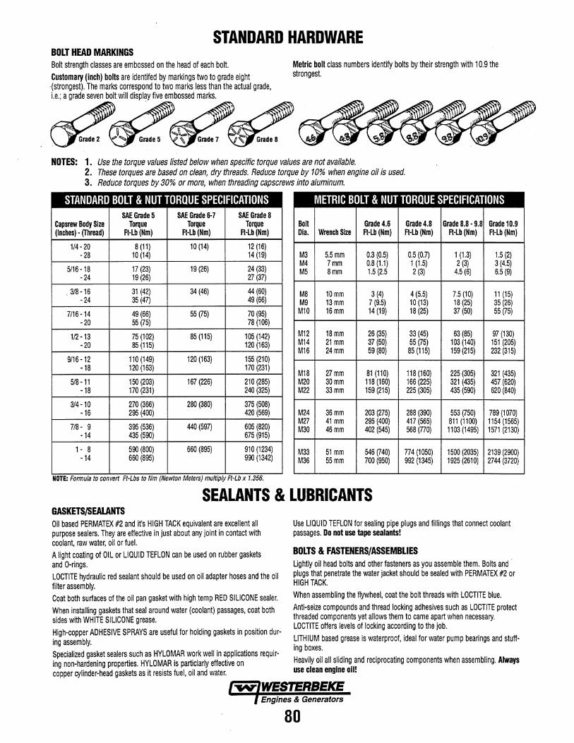
STANDARD HARDWARE BOLT HEAD MARKINGS Bolt strength classes are embossed on the head of each bolt. Metric bolt class numbers identify bolts by their strength with 10.9 the
strongest.
NOTES: 1. Use the torque values listed below when specific torque values are not available. 2. These torques are based on clean, dry threads. Reduce torque by 10% when engine oil is used. 3. Reduce torques by 30% or more, when threading capscrews into aluminum.
STANDARD BOLT & NUT TORQUE SPECIFICATIONS METRIC BOLT & NUT TORQUE SPECIFICATIONS SAE Grade 5 SAE Grade 6·7 SAE Grade 8
Capsrew Body Size Torque Torque Torque Bolt Grade 4.6 Grade 4.8 Grade 8.8 - 9.8 Grade 1D.9 (Inches) • (Thread) FHb(Nm) FHb(Nm) Ft·Lb(Nm) Dia. Wrench Size Ft-Lb (Nm) Ft-Lb (Nm) Ft-Lb (Nm) Ft-Lb (Nm)
1/4 - 20 8 (11) 10 (14) 12 (16) - 28 10 (14) 14 (19) M3 5.5mm 0.3 (0.5) 0.5 (0.7) 1 (1.3) 1.5 (2)
5116-18 17 (23) 19 (26) 24 (33) -24 19 (26) 27 (37)
M4 7mm 0.8 (1.1) 1 (1.5) 2 (3) 3 (4.5) M5 8mm 1.5 (2.5 2 (3) 4.5 (6) 6.5 (9)
.3/8-16 31 (42) 34 (46) 44 (60) -24 35 (47) 49 (66)
M8 10mm 3 (4) 4 (5.5) 7.5 (10) 11 (15) M9 13mm 7 (9.5) 10 (13) 18 (25) 35 (26)
7/16 -14 49 (66) 55 (75) 70 (95) Ml0 16mm 14 (19) 18 (25) 37 (50) 55 (75)
- 20 55 (75) 78 (106)
1/2 -13 75 (102) 85 (115) 105 (142) - 20 85 (115) 120 (163)
M12 18mm 26 (35) 33 (45) 63 (85) 97 (130) M14 21 mm 37 (SO) 55 (75) 103 (140) 151 (205) M16 24mm 59 (80) 85 (115) 159 (215) 232 (315)
9/16-12 110 (149) 120 (163) 155 (210) -18 120 (163) 170 (231)
M18 27mm 81 (110) 118 (160) 225 (305) 321 (435) 518-11 150 (203) 167 (226) 210 (285) M20 30mm 118 (160) 166 (225) 321 (435) 457 (620)
-18 170 (231) 240 (325) M22 33mm 159 (215) 225 (305) 435 (590) 620 (840)
3/4 -10 270 (366) 280 (380) 375 (508) -16 295 (400) 420 (569) M24 36mm 203 (275) 288 (390) 553 (750) 789 (1070)
7/8- 9 395 (536) 440 (597) 605 (820) -14 435 (590) 675 (915)
M27 41 mm 295 (400) 417 (565) 811 (1100) 1154 (1565) M30 46mm 402 (545) 568 (770) 1103 (1495) 1571 (2130)
1 - 8 590 (800) 660 (895) 910 (1234) -14 660 (895) 990 (1342)
M33 51 mm 546 (740) 774 (1050) 1500 (2035) 2139 (2900) M36 55mm 700 (950) 992 (1345) 1925 (2610) 2744 (3720)
NOTE: Formula to convert Ft-Lbs to Nm (Newton Meters) multiply Ft-Lb x 1.356.
SEALANTS & LUBRICANTS GASKETSf,SEALANTS Oil based PERMATEX #2 and it's HIGH TACK equivalent are excellent all purpose sealers. They are effective in just about any joint in contact with coolant, raw water, oil or fuel. A light coating of OIL or LIQUID TEFLON can be used on rubber gaskets and O-rings. LOCTITE hydraulic red sealant should be used on oil adapter hoses and the oil filter assembly. Coat both surfaces of the oil pan gasket with high temp RED SILICONE sealer. When installing gaskets that seal around water (coolant) passages, coat both sides with WHITE SILICONE grease. High-copper ADHESIVE SPRAYS are useful for holding gaskets in position during assembly. Specialized gasket sealers such as HYLOMAR work well in applications requiring non-hardening properties. HYLOMAR is particlarly effective on copper cylinder-head gaskets as it resists fuel, oil and water.
Use LIQUID TEFLON for sealing pipe plugs and fillings that connect coolant passages. Do not use tape sealants!
BOLTS & FASTENERS/ASSEMBLIES Lightly oil head bolts and other fasteners as you assemble them. Bolts and plugs that penetrate the water jacket should be sealed with PERMATEX #2 or HIGH TACK. When assembling the flywheel, coat the bolt threads with LOCTITE blue. Anti-seize compounds and thread locking adhesives such as LOCTITE protect threaded components yet allows them to came apart when necessary. LOCTITE offers levels of locking according to the job. LITHIUM based grease is waterproof, ideal for water pump bearings and stuffing boxes. Heavily oil all sliding and reciprocating components when assembling. Always use clean engine oil!
Engines & Generators
80
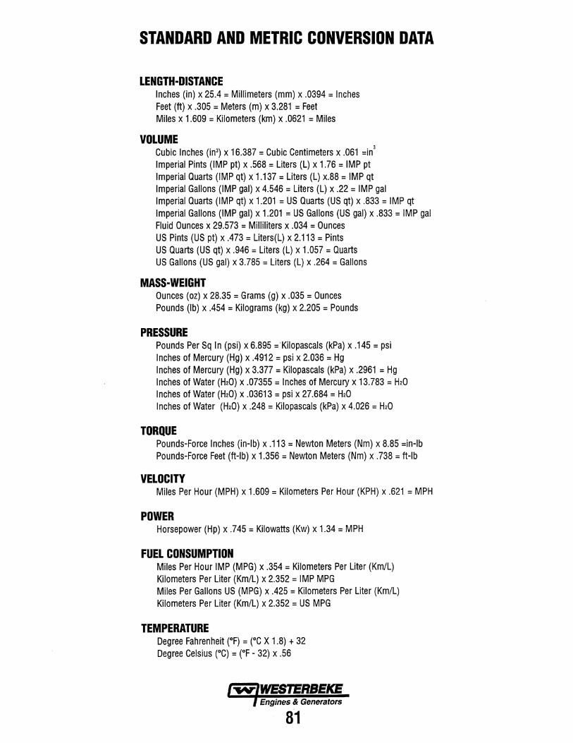
STANDARD AND METRIC CONVERSION DATA
LENGTH-DISTANCE Inches (in) x 25.4 = Millimeters (mm) x .0394 = Inches Feet (ft) x .305 = Meters (m) x 3.281 = Feet Miles x 1.609 = Kilometers (km) x .0621 = Miles
VOLUME Cubic Inches (in3) x 16.387 = Cubic Centimeters x .061 =in3
Imperial Pints (IMP pt) x .568 = Liters (L) x 1.76 = IMP pt Imperial Quarts (IMP qt) x 1.137 = Liters (L) x.88 = IMP qt Imperial Gallons (IMP gal) x 4.546 = Liters (L) x .22 = IMP gal Imperial Quarts (IMP qt) x 1.201 = US Quarts (US qt) x .833 = IMP qt Imperial Gallons (IMP gal) x 1.201 = US Gallons (US gal) x .833 = IMP gal Fluid Ounces x 29.573 = Milliliters x .034 = Ounces US Pints (US pt) x .473 = Liters(L) x 2.113 = Pints US Quarts (US qt) x .946 = Liters (L) x 1.057 = Quarts US Gallons (US gal) x 3.785 = Liters (L) x .264 = Gallons
MASS-WEIGHT Ounces (oz) x 28.35 = Grams (g) x .035 = Ounces Pounds (Ib) x .454 = Kilograms (kg) x 2.205 = Pounds
PRESSURE Pounds Per Sq In (psi) x 6.895 ='Kilopascals (kPa) x .145 = psi Inches of Mercury (Hg) x .4912 = psi x 2.036 = Hg Inches of Mercury (Hg) x 3.377 = Kilopascals (kPa) x .2961 = Hg Inches of Water (H20) x .07355 = Inches of Mercury x 13.783 = H20 Inches of Water (H20) x .03613 = psi x 27.684 = H20 Inches of Water (H20) x .248 = Kilopascals (kPa) x 4.026 = H20
TORQUE Pounds-Force Inches (in-Ib) x .113 = Newton Meters (Nm) x 8.85 =in-Ib Pounds-Force Feet (ft-Ib) x 1.356 = Newton Meters (Nm) x .738 = ft-Ib
VELOCITY Miles Per Hour (MPH) x 1.609 = Kilometers Per Hour (KPH) x .621 = MPH
POWER Horsepower (Hp) x .745 = Kilowatts (Kw) x 1.34 = MPH
FUEL CONSUMPTION Miles Per Hour IMP (MPG) x .354 = Kilometers Per Liter (Km/L) Kilometers Per Liter (Km/L) x 2.352 = IMP MPG Miles Per Gallons US (MPG) x .425 = Kilometers Per Liter (Km/L) Kilometers Per Liter (Km/L) x 2.352 = US MPG
TEMPERATURE Degree Fahrenheit (OF) = (OC X 1.8) + 32 Degree Celsius (0C) = (OF - 32) x .56
Engines & Generators
81
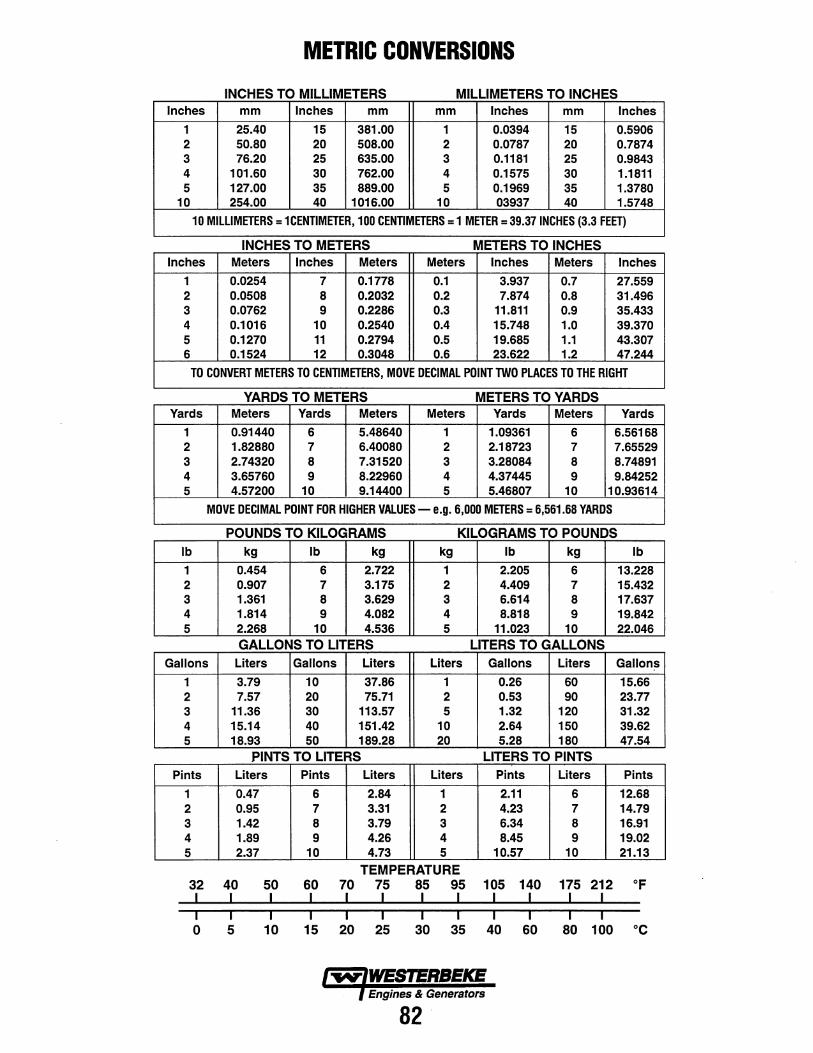
METRIC CONVERSIONS
INCHES TO MILLIMETERS MILLIMETERS TO INCHES Inches mm Inches mm mm Inches mm Inches
1 25.40 15 381.00 1 0.0394 15 0.5906 2 50.80 20 508.00 2 0.0787 20 0.7874 3 76.20 25 635.00 3 0.1181 25 0.9843 4 101.60 30 762.00 4 0.1575 30 1.1811 5 127.00 35 889.00 5 0.1969 35 1.3780
10 254.00 40 1016.00 10 03937 40 1.5748
10 MILLIMETERS = 1 CENTIMETER, 100 CENTIMETERS = 1 MmR = 39.37 INCHES (3.3 FEET)
INCHES TO METERS METERS TO INCHES Inches Meters Inches Meters Meters Inches Meters Inches
1 0.0254 7 0.1778 0.1 3.937 0.7 27.559 2 0.0508 8 0.2032 0.2 7.874 0.8 31.496 3 0.0762 9 0.2286 0.3 11.811 0.9 35.433 4 0.1016 10 0.2540 0.4 15.748 1.0 39.370 5 0.1270 11 0.2794 0.5 19.685 1.1 43.307 6 0.1524 12 0.3048 0.6 23.622 1.2 47.244
TO CONVERT METERS TO CENTIMETERS, MOVE DECIMAL POINT TWO PLACES TO THE RIGHT
YARDS TO METERS METERS TO YARDS Yards Meters Yards Meters Meters Yards Meters Yards
1 0.91440 6 5.48640 1 1.09361 6 6.56168 2 1.82880 7 6.40080 2 2.18723 7 7.65529 3 2.74320 8 7.31520 3 3.28084 8 8.74891 4 3.65760 9 8.22960 4 4.37445 9 9.84252 5 4.57200 10 9.14400 5 5.46807 10 10.93614
MOVE DECIMAL POINT FOR HIGHER VALUES - e.g. 6,000 MmRS = 6,561.68 YARDS
POUNDS TO KILOGRAMS KILOGRAMS TO POUNDS Ib kg Ib kg kg Ib kg Ib
1 0.454 6 2.722 1 2.205 6 13.228 2 0.907 7 3.175 2 4.409 7 15.432 3 1.361 8 3.629 3 6.614 8 17.637 4 1.814 9 4.082 4 8.818 9 19.842 5 2.268 10 4.536 5 11.023 10 22.046
GALLONS TO LITERS LITERS TO GALLONS Gallons Liters Gallons Liters Liters Gallons Liters Gallons
1 3.79 10 37.86 1 0.26 60 15.66 2 7.57 20 75.71 2 0.53 90 23.77 3 11.36 30 113.57 5 1.32 120 31.32 4 15.14 40 151.42 10 2.64 150 39.62 5 18.93 50 189.28 20 5.28 180 47.54
PINTS TO LITERS LITERS TO PINTS Pints Liters Pints Liters Liters Pints Liters Pints
1 0.47 6 2.84 1 2.11 6 12.68 2 0.95 7 3.31 2 4.23 7 14.79 3 1.42 8 3.79 3 6.34 8 16.91 4 1.89 9 4.26 4 8.45 9 19.02 5 2.37 10 4.73 5 10.57 10 21.13
TEMPERATURE 32 40 50 60 70 75 85 95 105 140 175 212 OF I I I I I I I I I I I I I I I I I I I I I I I I 0 5 10 15 20 25 30 35 40 60 80 100 °C
Engines & Generators
82
INDEX AC Connection Diagrams ................... 75 Ignition Wires ........................... .46 Actuator ................................ 61 Integral Controller ......................... 73 Battery Charging Circuit ................. 51 &72 Internal Wiring Diagrams ................... 75 BCGT Electrical Testing .................... 69 Magnetic Pick-up Coil ..................... 63 BCGTE Wiring Diagrams ................ 66&67 Main Stator Windings Testing ................ 74 Belt Adjustment ......................... .46 Map Sensor .............................. 62 Bridge Rectifier ........................... 73 Metric Conversion [Chart] ................... 82 Capacitors -Testing ........................ 72 Metric Formulas .......................... 81 Carburetor - Rebuilding .................... .43 Oil Pressure Switch ....................... .48 Carburetor Adjustment .................... .45 Oil Pressure Testing ...................... .48 Choke Solenoid .......................... .45 Parts Identification ......................... 3 Compression Test ........................ .48 Piston Clearance .......................... 33 Coolant Circulating Pump ................... 35 Raw Water Pump ......................... 37 Cylinder Block Inspection ................... 33 Relays .............................. 50&60 Cy linder Head Torquing ................... .49 Remote Panels Wiring Diagram ........... .54,68 Diodes - Testing .......................... 70 Rotor Windings - Testing .................... 70 Distributor .............................. .34 Sealants & Lubricants ................... 7&80 ECU - Adjustments ........................ 57 Spark Plugs ............................. .46 ECU - Replacing/lnstalling .................. 59 Specifications ............................. 2 EFI Component Testing ..................... 62 Speed Hertz Adjustment ................... .47 EFI Components Troubleshooting ............. 55 Standards and Limits ....................... 76 EFI Control Circuit ........................ 56 Starter Motor - Adjustment ............... 39&42 Engine Disassembly and Inspection ....... 9-33 Starter Motor - Inspection .................. .40
CamshaftIRocker Arms ................... 19 Suppressor - Testing ....................... 70 Crankshaft Bearing Assembly .............. 24 Thermostat .............................. 38 CrankshaftlBearings & Oil Seal ........... .31 Timing Belt ........................... 11,49 Cylinder BlocklPiston Clearance ........... .33 Tools - Special ........................... 78 Cylinder Head Installation ................. 18 Troubleshooting Charts Cylinder HeadlValves .................... 15 Front Case/ Counterbalance Shaft ........... 26 Oil Pan ............................. 26,29 Oil Pump ........................... 27,29 Pistons/Connecting Rods .................. 21 Timing Belt ............................ 11
Control Circuit ......................... 58 Engine ................................ 5 Generator - Electrical .................... 69 Generator Operating Procedures ............ 64
Valve Clearance Adjustment ................ .49 Wiring Diagrams/Schematics
AC Connections ........................ 75 Exciter Windings - Testing .................. 71 BCGTC ............................ 52,53 Exhaust Manifold ......................... 36 BCGTE ............................ 66,67 Fuel Injector ............................. 61 Fuel Pressure Test ......................... 61 Fuel Pump ............................... 38
Generator - Internal ...................... 75 Remote Panels [BCGTC] ................. 54 Remote Panels [BCGTE] ................. 68
Gasdenser ............................... 38 Generator Disassembly ...................... 8 Generator Troubleshooting [Chart] ............ 64 Governor Adjustments ..................... .47 Hardware Standards ..................... 7&80 Hardware Torques ......................... 79 Heat Exchanger ........................... 36 Ignition Timing .......................... .49
Engines & Generators
83

Engines & Generators
1006 WMJDW 10/99