service guide compact disc recorder pdr … · 19rw) is the first series of cd recorders from...
TRANSCRIPT

ORDER NO.
PIONEER CORPORATION 4-1, Meguro 1-chome, Meguro-ku, Tokyo 153-8654, JapanPIONEER ELECTRONICS SERVICE, INC. P.O. Box 1760, Long Beach, CA 90801-1760, U.S.A.PIONEER ELECTRONIC (EUROPE) N.V. Haven 1087, Keetberglaan 1, 9120 Melsele, BelgiumPIONEER ELECTRONICS ASIACENTRE PTE. LTD. 253 Alexandra Road, #04-01, Singapore 159936 PIONEER CORPORATION 1999c
PDR-555RWRRV2055
T – IZK AUG. 1999 Printed in Japan
PDR-V500
COMPACT DISC RECORDER
PDR-19RWPDR-509
SERVICE GUIDE
2
PDR-555RW, PDR-V500, PDR-19RW, PDR-509
1. BLOCK DIAGRAM ........................................................................................................... 41.1 PDR-555RW, PDR-V500 AND PDR-19RW ............................................................................. 41.2 PDR-509 ................................................................................................................................... 6
2. PRODUCT DESCRIPTIONS ........................................................................................... 8
3. PORT TABLE OF MICROCOMPUTER ........................................................................... 93.1 MODE CONTROL OF PDR-555RW, PDR-V500 AND PDR-19RW ......................................... 93.2 MECHANISM CONTROL OF PDR-555RW, PDR-V500 AND PDR-19RW............................ 113.3 MODE CONTROL OF PDR-509 ............................................................................................ 143.4 MECHANISM CONTROL OF PDR-509 ................................................................................. 16
4. PIN FUNCTION OF PRINCIPAL IC ............................................................................... 194.1 AD1893JST ............................................................................................................................ 194.2 BR93LC46AF ......................................................................................................................... 194.3 LC89585 ................................................................................................................................. 204.4 LH64256CK-70 ....................................................................................................................... 224.5 PA9004A ................................................................................................................................ 224.6 PDJ014A ................................................................................................................................ 234.7 PDK033A or PDK041A ........................................................................................................... 244.8 AK5340-VS ............................................................................................................................. 254.9 PD0236AD.............................................................................................................................. 264.10 PCM1800-1 .......................................................................................................................... 26
5. RECORDING MECHANISM FOR CD-Rs AND CD-RWs .............................................. 275.1 DISC ....................................................................................................................................... 275.2 OVERWRITE RECORDING OF CD-RW ............................................................................... 27
6. PICKUP (KRS-200A) ..................................................................................................... 28
7. CIRCUIT DESCRIPTIONS ............................................................................................ 297.1 SERVO CIRCUITS ................................................................................................................. 29
7.1.1 Control Circuit for the Laser Diode .................................................................................. 297.1.2 Error Signal Generation Circuit ....................................................................................... 297.1.3 Focus Servo .................................................................................................................... 297.1.4 Tracking Thread Servo ................................................................................................... 297.1.5 Spindle Servo .................................................................................................................. 29
7.2 DEFECT CIRCUIT.................................................................................................................. 307.3 EFM-DIGITAL PLL ................................................................................................................. 307.4 RF DETECTION ..................................................................................................................... 307.5 MIRROR CIRCUIT ................................................................................................................. 307.6 AUDIO CIRCUITS .................................................................................................................. 30
7.6.1 Analog Audio Input .......................................................................................................... 307.6.2 A/D Converter ................................................................................................................. 307.6.3 Hi-bit IC (PDR-19RW Only) ............................................................................................ 317.6.4 D/A Converter ................................................................................................................. 317.6.5 Analog Audio Output Block ............................................................................................. 31
7.7 DIGITAL CIRCUITS................................................................................................................. 317.7.1 Digital Audio Interface Input Block .................................................................................. 317.7.2 Sampling Rate Converter ................................................................................................ 317.7.3 Clock-jitter Suppressor Circuit (PDR-509 Only) .............................................................. 317.7.4 Data Selector .................................................................................................................. 317.7.5 Digital Fader, Level Meter, Mute Blocks ......................................................................... 317.7.6 Memory Control .............................................................................................................. 317.7.7 EFM Encoding ................................................................................................................ 327.7.8 Strategy Control .............................................................................................................. 327.7.9 Digital Audio Interface Modulation .................................................................................. 32
CONTENTS

3
PDR-555RW, PDR-V500, PDR-19RW, PDR-509
8. DETAILED DESCRIPTIONS OF OUTPUT TERMINAL CONTROL .............................. 328.1 DGAI (microcomputer,pin 48)and D8CM (microcomputer,pin 53)TERMINAL CONTROL ..... 328.2 AGCON (ATIP decoder, pin 52) TERMINAL CONTROL ....................................................... 328.3 XCD (ATIP decoder, pin 69) TERMINAL CONTROL ............................................................. 338.4 GAINUP1 (ATIP decoder, pin 45) RW/XR (ATIP decoder, pin 66) TERMINAL CONTROL... 338.5 CDROPC (ATIP decoder, pin 46) TERMINAL CONTROL ..................................................... 338.6 GAINUP3 (ATIP decoder, pin 47) TERMINAL CONTROL ..................................................... 338.7 PHYERS (ATIP decoder, pin 52) TERMINAL CONTROL ...................................................... 338.8 SSEL (ATIP decoder, pin 51) TERMINAL CONTROL ........................................................... 338.9 ENBL (ATIP decoder, pin 70) TERMINAL CONTROL ........................................................... 33
9. OPERATION DESCRIPTIONS ...................................................................................... 349.1 ABOUT POWER ON/OFF ...................................................................................................... 34
9.1.1 Power-up (When the power outlet is active) ................................................................... 349.1.2 Power Down (When the power outlet is not active or power failure occurs) ................... 34
9.2 ABOUT SERVO CONTROL ................................................................................................... 349.2.1 Seek Track 0 ................................................................................................................... 349.2.2 Focus ON ........................................................................................................................ 349.2.3 One-Track Jump (Direct Sequence) ............................................................................... 359.2.4 One-Track Jump (Auto Sequence) ................................................................................. 359.2.5 Ten-Track Jump .............................................................................................................. 359.2.6 2N-Track Jump ............................................................................................................... 359.2.7 M-Track Move ................................................................................................................. 369.2.8 Fine Search ..................................................................................................................... 369.2.9 Loading Control ............................................................................................................... 369.2.10 Spindle Control ............................................................................................................. 37
9.3 ERASING (CD-RW ONLY) ..................................................................................................... 379.3.1 Last-Track-Erase Operation ............................................................................................ 379.3.2 All-Track-Erase Operation .............................................................................................. 379.3.3 TOC-Erase Operation ..................................................................................................... 379.3.4 ALL-Disc-Erase Operation .............................................................................................. 379.3.5 PCA-Erase Operation ..................................................................................................... 37
9.4 RID CODES............................................................................................................................ 379.5 DISC JUDGMENT .................................................................................................................. 38
9.5.1 Tentative Judgment Using FZC (Distinguishing Between CD/CD-R and CD-RW) ......... 389.5.2 Disc Judgment with Each Type of Disc ........................................................................... 38
9.6 SETUP (FLOW) ...................................................................................................................... 399.6.1 Verification of Disc Judgments ........................................................................................ 409.6.2 Auto-Adjustments ............................................................................................................ 409.6.3 Tracking Error Level Adjustment and Disc Determination .............................................. 409.6.4 Recording Power Sweep Mode for Recording Power Calibration .................................. 419.6.5 Playback RF Estimating Mode for Recording Power Calibration .................................... 41
10. ABOUT TEST MODE OPERATIONS ......................................................................... 41
11. ERROR CODES ......................................................................................................... 4511.1 ERROR CODE DISPLAY FOR SERVICE............................................................................ 4511.2 ABOUT FULL ERROR CODES............................................................................................ 47

4
PDR-555RW, PDR-V500, PDR-19RW, PDR-509
SPDL MOTOR
SLD MOTOR
FG
A–D RFDC
RFOPCAOUT
RFDC
FE
WRF
TERFAC
TEHF
RFWBL
HF
68–7173–76
A–HPICKUP ASSY
KRS-200A
RF AMP CIRCUITIC102, IC101
IC103AK8563
RF PROCESSOR
RUNNING OPC CIRCUIT BLOCK
IC247 PA9004A
SERVO AMP
IC353 CXD2585Q
CD DECODER
IC205 PDJ014A
ATIP DECODERIC
IC316 PDK033A
STRATEGYCONTROL IC
LD CONTROL CIRCUIT
IC351BA5912AFP-YSLD DRIVER
SPDL DRIVER
IC352BA5932FP
FCS DRIVERTRK DRIVER
LOADING DRIVER
IC701PD4968A
MODE CONTROL MICROCOMPUTER
IC705PYY1196 EEPROM
FL DISPLAY PEL1097
KEY MATRIX
RESET ICS-806E
Disc (CD, CD-R, CD-RW)
LOADING MOTOR
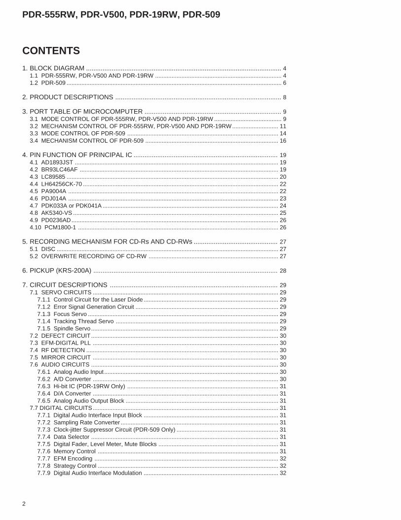
1. BLOCK DIAGRAM1.1 PDR-555RW, PDR-V500 AND PDR-19RW
5
PDR-555RW, PDR-V500, PDR-19RW, PDR-509
RFOPC(60 pin)AOUT(61 pin)
CDLRCK, CDBCK CDDATA, CDTX
DIRBCK DIRLRCK DIRDATA
ADLRCK ADBCK ADDATA
DATAADDRESS
DALRCK DADATA DABCK
PDR-19RW ONLY
34.5744MHz
17.2872MHz
16.9344MHz
AD0-AD7
ADDRESS
IC204 PD4956A
MECH. CONTROL MICROCOMPUTER
IC308 LC89585
EFM ENCODER ICWAVEFORM
SHAPING CIRCUIT
IC309 BA7082F VCO IC
IC301 LH64256CK-70
D-RAM
IC451 PD0236AD
Hi-Bit
IC801 AK5340-VS
AD CONVERTER
INPUT Lch Rch
HPOUTPUT
Digital in COAXIAL
Digital in OPTICAL
Digital out OPTICAL
Digital out COAXIAL
IC401 PE8001A
DA CONVERTERIC405
IC406
REC VR
IC311 AD1893JST
Fs CONVERTER
TEMPERATURESENSOR ICTK11041M
IC704BU2092F
LED DRIVER IC
MODE DISPLAY LED D707, D708
OUTPUT
L ch
R ch

6
PDR-555RW, PDR-V500, PDR-19RW, PDR-509
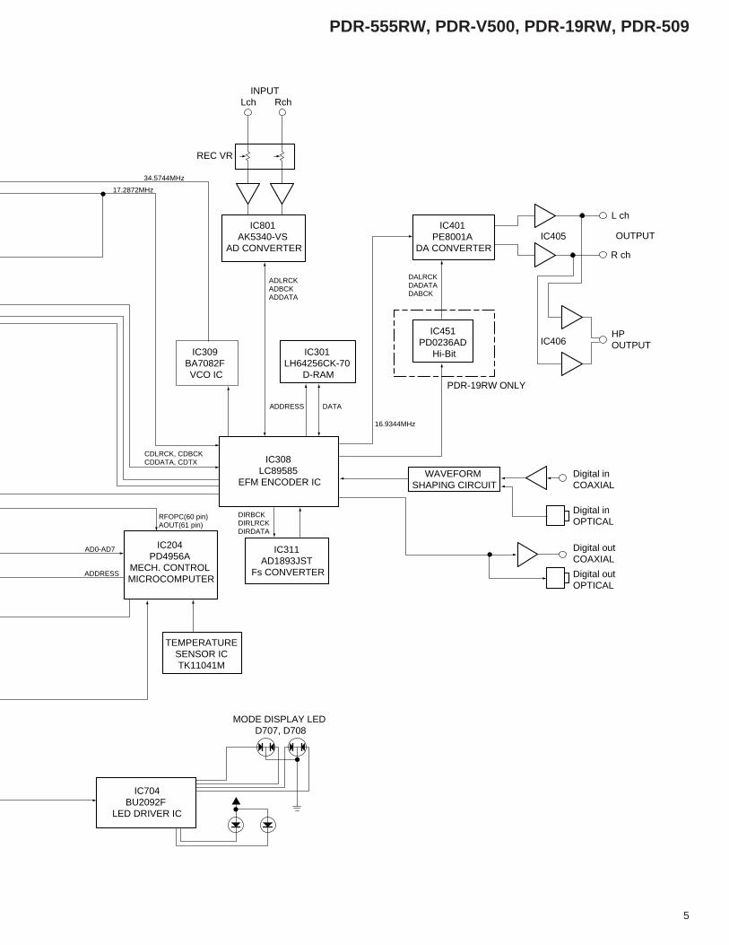
1.2 PDR-509
SPDL MOTOR
SLD MOTOR
FG
A–D RFDC
RFOPCAOUT
RFDC
FE
WRF
TERFAC
TEHF
RFWBL
HF
68–7173–76
A–HPICKUP ASSY
KRS-200A
RF AMP CIRCUITIC181
IC101AK8563
RF PROCESSOR
RUNNING OPC CIRCUIT BLOCK
IC201 PA9007A
SERVO AMP IC
IC401 CXD2585Q
CD DECODER
IC351 PDJ014A
ATIP DECODERIC
IC431 PDK041A
STRATEGYCONTROL IC
LD CONTROL CIRCUIT
IC451M56788FP
TRK DRIVERFCS DRIVERSLD DRIVER
SPDL DRIVERLOADING DRIVER
IC701PE5110B
MODE CONTROL MICROCOMPUTER
IC303PYY1196 EEPROM
FL DISPLAY PEL1097
KEY MATRIX
RESET ICS-806E
Disc (CD, CD-R, CD-RW)
LOADING MOTOR
7
PDR-555RW, PDR-V500, PDR-19RW, PDR-509
RFOPC(60 pin)AOUT(61 pin)
CDLRCK, CDBCK CDDATA, CDTX
DIRBCK DIRLRCK DIRDATA
ADLRCK ADBCK ADDATA
DATAADDRESS
DALRCK DADATA DABCK
34.5744MHz
17.2872MHz
16.9344MHz
AD0-AD7
ADDRESS
IC301 PE5109A
MECH. CONTROL MICROCOMPUTER
IC501 LC89585
EFM ENCODER IC
IC561 BA7082F VCO IC
IC503 LH64256CK-70
D-RAM
IC802 PCM1800-1
AD CONVERTER
INPUT Lch Rch
HPOUTPUT
Digital in COAXIAL
Digital in OPTICAL
Digital out OPTICAL
Digital out COAXIAL
IC401
DA CONVERTERIC405
IC406
REC VR
IC502 AD1893JST
Fs CONVERTER
TEMPERATURESENSOR ICTK11041M
MODE DISPLAY LED D704
D701D702
OUTPUT
L ch
R ch
16.9344MHz
MY, MV TYPES : PE8001A
KU/CA TYPE : PCM1718

8
PDR-555RW, PDR-V500, PDR-19RW, PDR-509
The PDR-555RW series (PDR-555RW, PDR-V500 and PDR-19RW) is the first series of CD recorders from PIONEER thatsupports recording and erasing of CD-RW discs. Basic operationswith CDs and CD-Rs with this series are based on those of the CDrecorders of the PDR-05 series.The main differences from the PDR-05 series concerning the circuitsare:• The pickup is changed.• The circuit in RF amplifier is changed.• The LD drive circuit (including the strategy control circuit) is changed.• A running OPC circuit is added.• The focus servo, tracking servo and sled servo are digitized.• The driver IC is changed.• The CD decoder IC is changed.• The sampling rate converter IC is changed.• The DA converter is changed.
Also, the circuits of the CD recorders of the PDR-509 series arebased on those of the PDR-555RW series. So the main circuitsused in the PDR-509 series are equivalent to those of the PDR-555RW series. But as an exception, AD converter is changed to theAK5340-VS from the PCM1800-1.
2. PRODUCT DESCRIPTIONS
9
PDR-555RW, PDR-V500, PDR-19RW, PDR-509
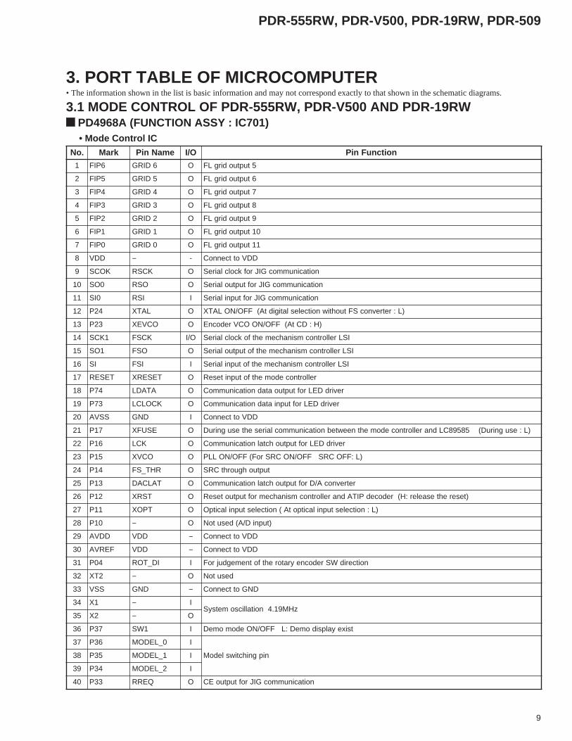
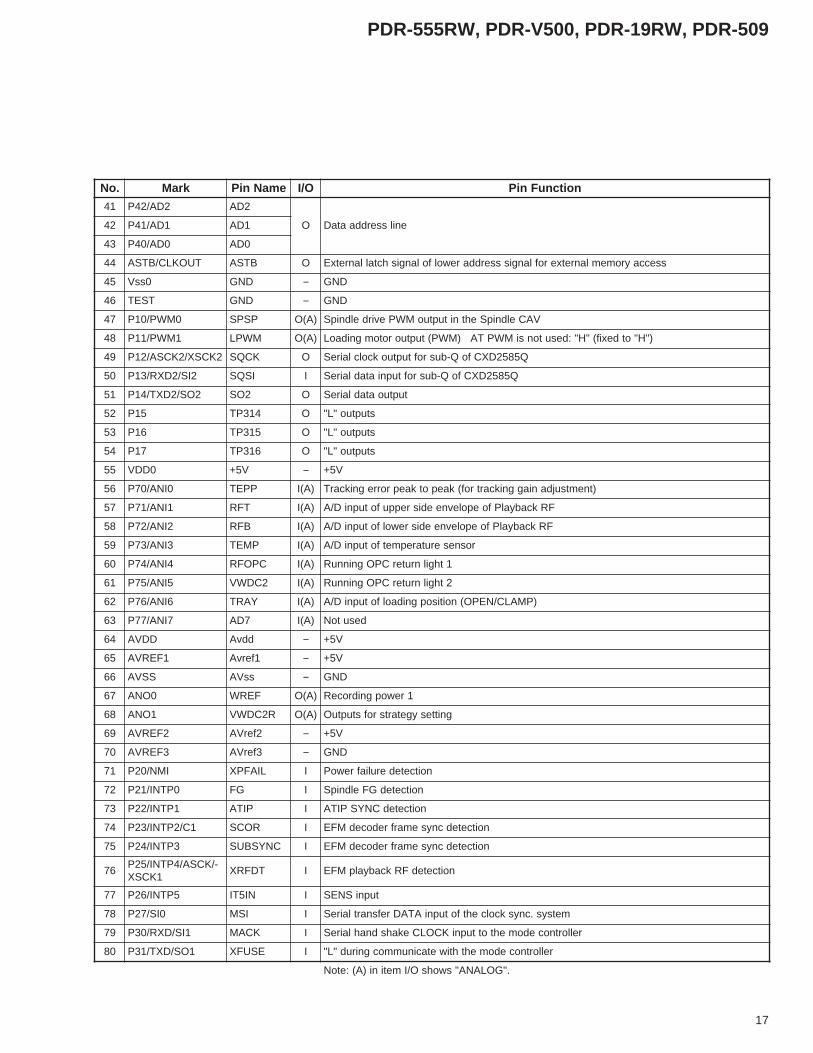
3. PORT TABLE OF MICROCOMPUTER
3.1 MODE CONTROL OF PDR-555RW, PDR-V500 AND PDR-19RW
.oN kraM emaNniP O/I noitcnuFniP
1 6PIF 6DIRG O 5tuptuodirgLF
2 5PIF 5DIRG O 6tuptuodirgLF
3 4PIF 4DIRG O 7tuptuodirgLF
4 3PIF 3DIRG O 8tuptuodirgLF
5 2PIF 2DIRG O 9tuptuodirgLF
6 1PIF 1DIRG O 01tuptuodirgLF
7 0PIF 0DIRG O 11tuptuodirgLF
8 DDV − - DDVottcennoC
9 KOCS KCSR O noitacinummocGIJrofkcolclaireS
01 0OS OSR O noitacinummocGIJroftuptuolaireS
11 0IS ISR I noitacinummocGIJroftupnilaireS
21 42P LATX O )L:retrevnocSFtuohtiwnoitceleslatigidtA(FFO/NOLATX
31 32P OCVEX O )H:DCtA(FFO/NOOCVredocnE
41 1KCS KCSF O/I ISLrellortnocmsinahcemehtfokcolclaireS
51 1OS OSF O ISLrellortnocmsinahcemehtfotuptuolaireS
61 IS ISF I ISLrellortnocmsinahcemehtfotupnilaireS
71 TESER TESERX O rellortnocedomehtfotupniteseR
81 47P ATADL O revirdDELroftuptuoatadnoitacinummoC
91 37P KCOLCL O revirdDELroftupniatadnoitacinummoC
02 SSVA DNG I DDVottcennoC
12 71P ESUFX O )L:esugniruD(58598CLdnarellortnocedomehtneewtebnoitacinummoclairesehtesugniruD
22 61P KCL O revirdDELroftuptuohctalnoitacinummoC
32 51P OCVX O )L:FFOCRSFFO/NOCRSroF(FFO/NOLLP
42 41P RHT_SF O tuptuohguorhtCRS
52 31P TALCAD O retrevnocA/DroftuptuohctalnoitacinummoC
62 21P TSRX O )teserehtesaeler:H(redocedPITAdnarellortnocmsinahcemroftuptuoteseR
72 11P TPOX O )L:noitcelestupnilacitpotA(noitcelestupnilacitpO
82 01P − O )tupniD/A(desutoN
92 DDVA DDV − DDVottcennoC
03 FERVA DDV − DDVottcennoC
13 40P ID_TOR I noitceridWSredocneyratorehtfotnemegdujroF
23 2TX − O desutoN
33 SSV DNG − DNGottcennoC
43 1X − IzHM91.4noitallicsometsyS
53 2X − O
63 73P 1WS I tsixeyalpsidomeD:LFFO/NOedomomeD
73 63P 0_LEDOM I
nipgnihctiwsledoM83 53P 1_LEDOM I
93 43P 2_LEDOM I
04 33P QERR O noitacinummocGIJroftuptuoEC
PD4968A (FUNCTION ASSY : IC701) • Mode Control IC
• The information shown in the list is basic information and may not correspond exactly to that shown in the schematic diagrams.

10
PDR-555RW, PDR-V500, PDR-19RW, PDR-509
.oN kraM emaNniP O/I noitcnuFniP
14 23P KCAM O rellortnocmsinahcemrofesnopsernoitacinummoC
24 13P QERL O 58598CLroflangisEC
34 03P KCOLNU I noitcetedkcolnulatigiD
44 3PTNI TNI_TOP I (noitcetednoitarepoWSredocneyratoR ↓ )tpurretni
54 2PTNI LIAFPX I noitcetednwodrewoP
64 1PTNI QERM I )tpurretni(tseuqernoitacinummocrellortnocmsinahceM
74 0PTNI NIMER I )tpurretni(tupnilortnocetomeR
84 CI PPV I DNGottcennoC
94 27P 3LESI I )noitcelesgolanA:H(3tupniWSyratorrotcelestupnI
05 17P 2LESI I )noitceleslacitpO:H(2tupniWSyratorrotcelestupnI
15 07P 1LESI I )noitceleslaixaoC:H(1tupniWSyratorrotcelestupnI
25 DDV DDV − DDVottcennoC
35 721P 4NACS O 4tuptuoxirtamyeK
45 621P 3NACS O 3tuptuoxirtamyeK
55 521P 2NACS O 2tuptuoxirtamyeK
65 421P 1NACS O 1tuptuoxirtamyeK
75 321P 0NACS O 0tuptuoxirtamyeK
85 221P 3NIYEK I 3tupnixirtamyeK
95 121P 2NIYEK I 2tupnixirtamyeK
06 021P 1NIYEK I 1tupnixirtamyeK
16 711P 0NIYEK I 0tupnixirtamyeK
26 611P V0_TTA I
36 511P TALTAA O
46 411P GES_LNIF O )H:pusthgiltA(tuptuotnemges"EZILANIF"
56 311P 01GES O 01tuptuotnemgesLF
66 211P 9GES O 9tuptuotnemgesLF
76 111P 8GES O 8tuptuotnemgesLF
86 011P 7GES O 7tuptuotnemgesLF
96 701P 6GES O 6tuptuotnemgesLF
07 601P 5GES O 5tuptuotnemgesLF
17 DAOLV DAOLV − DAOLV
27 501P 4GES O 4tuptuotnemgesLF
37 401P 3GES O 3tuptuotnemgesLF
47 301P 2GES O 2tuptuotnemgesLF
57 201P 1GES O 1tuptuotnemgesLF
67 101P 0GES O 0tuptuotnemgesLF
77 001P 01DIRG O 01tuptuodirgLF
87 9PIF 9DIRG O 9tuptuodirgLF
97 8PIF 8DIRG O 8tuptuodirgLF
08 7PIF 7DIRG O 7tuptuodirgLF

11
PDR-555RW, PDR-V500, PDR-19RW, PDR-509
3.2 MECHANISM CONTROL OF PDR-555RW, PDR-V500 AND PDR-19RW
PD4956B (SERVO DIGITAL ASSY : IC204) • Mechanism Control IC
.oN kraM emaNniP O/I noitcnuFniP
1 LCS/0KLCX/23P KCSM )I(O metsyssuonorhcnyskcolcfotuptuokcolcrefsnartlaireS
2 ADS/0OS/33P OSM )I(O metsyssuonorhcnyskcolcfotuptuoatadrefsnartlaireS
3 0OT/43P − O desutoN
4 1OT/53P 0NCTS O )cesn03+yaledT3(tnemtsujdaygetartsrofstuptuO
5 2OT/63P KOF I )KOSUCOF:H(tupniKOSUCOF
6 3OT/73P TSRL O )teseR:L(sCImetsyslatigiddnaovresehtroftuptuoTESER
7 TESERX TESERX I )teseR:L(tupniTESER
8 1DDV 5V+ − noitcestropgnitpecxeylppusrewopevitisoP
9 2X KCOLC I )zHM23(kcolcmetsysroftupnilatsyrC
01 1X KCOLC − )zHM23(kcolcmetsysroftuptuolatsyrC
11 1SSV DNG − noitcestropgnitpecxeDNG
21 00P ECEX O tsetrofgijehtgnidaerroftuptuoelbanE
31 10P ECER O H:NOFFO/NOrewopgnidroceredoidresaL
41 20P CN O desutoN
51 30P CN O desutoN
61 40P LES5TI O )PCOT:L,SNES:H(nip5PTNIfohctiwstupnI
71 50P ECNEX O 58598CLfotuptuoelbanecnyslanretxE
81 60P CNYSAX O cnysemarfPITA
91 70P ECNEX )I(O 58598CLfotuptuoelbanelaireS
02/QRFERX/76P
KADLHVLC O edomVAC/VLCovreseldnipS
12/TIAWX/66P
QRDLHVLCE O edomelbboW/MFEovreseldnipS
22 RWX/56P RWX O yromemlanretxeehtfonoitarepoDAERroftuptuolangisebortS
32 DRX/46P DRX O yromemlanretxeehtfonoitarepoETIRWroftuptuolangisebortS
42 91A/36P TLX O dnammocQ5852DXCfotuptuohctaL
52 81A/26P KCSS O dnammocQ5852DXCroftuptuokcolclaireS
62 71A/16P OSS O dnammocQ5852DXCroftuptuoatadlaireS
72 61A/06P TALA O dnammoc3658KAroftuptuohctaL
82 51A/75P KLCS O Q5852DXCfotuodaerlairesroftuptuokcolclaireS
92 41A/65P P2_PTO niptseT
03 31A/55P P1_PT
13 21A/45P 4WPDL
O gnittestuptuorewopresalgnidroceR
23 11A/35P 3WPDL
33 01A/25P 2WPDL
43 9A/15P 1WPDL
53 8A/05P 0WPDL
63 7DA/74P 7DA
O enilsserddaataD
73 6DA/64P 6DA
83 5DA/54P 5DA
93 4DA/44P 4DA
04 3DA/34P 3DA

12
PDR-555RW, PDR-V500, PDR-19RW, PDR-509
.oN kraM emaNniP O/I noitcnuFniP
14 2DA/24P 2DA
O enilsserddaataD24 1DA/14P 1DA
34 0DA/04P 0DA
44 TUOKLC/BTSA BTSA O sseccayromemlanretxeroflangissserddarewolfolangishctallanretxE
54 0ssV DNG − noitcestropfoDNG
64 TSET DNG − 0ssVottcennoC
74 0MWP/01P PSPS O VACeldnipSehtnituptuoMWPevirdeldnipS
84 1MWP/11P IAGD OdnaDCehtfosetunim81morfyrehpirepretuorof"L"semocebti,edomCERroYALPehtnI
.R-DCmc8ehtfosetunim9morfyrehpirepretuorof"H"dna,R-DCmc21
94 2KCSX/2KCSA/21P KCQS O Q5852DXCfoQ-busroftuptuokcolclaireS
05 2IS/2DXR/31P ISQS I Q5852DXCfoQ-busroftupniatadlaireS
15 2OS/2DXT/41P 2OS O tuptuoatadlaireS
25 51P QERM O rellortnocedomehtottuptuoekahsdnahlaireS
35 61P MC8D O H:mc8csidR-DCmc8
45 71P CN O desutoN
55 0DDV V5+ − noitcestropfoylppusrewopevitisoP
65 0INA/07P PPET )A(I )tnemtsujdaniaggnikcartrof(kaepotkaeprorregnikcarT
75 1INA/17P TFR )A(I FRkcabyalPfoepolevneedisreppufotupniD/A
85 2INA/27P BFR )A(I FRkcabyalPfoepolevneedisrewolfotupniD/A
95 3INA/37P PMET )A(I rosneserutarepmetfotupniD/A
06 4INA/47P CPOFR )A(I TUOXPM/CPOFRfotupniD/A
16 5INA/57P 2CDWV )A(I tnemtsujdaygetartsroftupniD/A
26 6INA/67P YART )A(I noitisopgnidaolfotupniD/A
36 7INA/77P 7DA )A(I desutoN
46 DDVA V5+ − retrevnocD/ArofylppusrewopevitisoP
56 1FERVA V5+ − retrevnocD/AroftupniegatlovecnerefeR
66 SSVA DNG − retrevnocD/ArofDNG
76 0ONA FERW )A(O ecnereferCPAgnidrocerroftuptuoA/D
86 1ONA R2CDWV )A(O tnemtsujdaygetartsroftuptuoA/D
96 2FERVA V5+ − retrevnocA/DrofegatlovecnerefeR
07 3FERVA DNG − retrevnocA/DrofegatlovecnerefeR
17 IMN/02P LIAFPX I egdegnillaf:eruliafrewopTAnoitcetederuliafrewoP
27 0PTNI/12P GF I tupniGFeldnipS
37 1PTNI/22P PITA I tupniCNYSPITA
47 1C/2PTNI/32P ROCS I Q5852DXCfocnysemarF
57 3PTNI/42P CNYSBUS I 58598CLfocnysemarF
67/KCSA/4PTNI/52P
1KCSXTDFRX I noitcetedFRkcabyalpMFE
77 5PTNI/62P NI5TI I Q5852DXCfotupnilangisSNES,)L:noitisopCOT(rosnesnoitisopCOT
87 0IS/72P ISM I metsys.cnyskcolcehtfotupniatadrefsnartlaireS
97 1IS/DXR/03P KCAM I rellortnocedomehtottupniekahsdnahlaireS
08 1OS/DXT/13P ESUFX I rellortnocedomehtdna58598CLneewtebnoitacinummocgnirudsihcihwlangiS
."GOLANA"swohsO/Imetini)A(:etoN
13
PDR-555RW, PDR-V500, PDR-19RW, PDR-509
.oN kraM emaNniP O/I noitcnuFniP
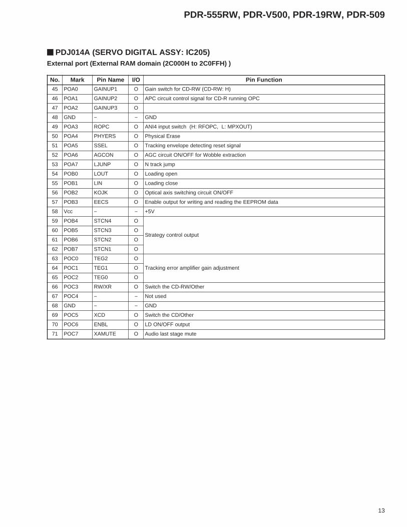
54 0AOP 1PUNIAG O )H:WR-DC(WR-DCrofhctiwsniaG
64 1AOP 2PUNIAG O CPOgninnurR-DCroflangislortnoctiucricCPA
74 2AOP 3PUNIAG O
84 DNG − − DNG
94 3AOP CPOR O )TUOXPM:L,CPOFR:H(hctiwstupni4INA
05 4AOP SREYHP O esarElacisyhP
15 5AOP LESS O langistesergnitcetedepolevnegnikcarT
25 6AOP NOCGA O noitcartxeelbboWrofFFO/NOtiucricCGA
35 7AOP PNUJL O pmujkcartN
45 0BOP TUOL O nepognidaoL
55 1BOP NIL O esolcgnidaoL
65 2BOP KJOK O FFO/NOtiucricgnihctiwssixalacitpO
75 3BOP SCEE O atadMORPEEehtgnidaerdnagnitirwroftuptuoelbanE
85 ccV − − V5+
95 4BOP 4NCTS O
tuptuolortnocygetartS06 5BOP 3NCTS O
16 6BOP 2NCTS O
26 7BOP 1NCTS O
36 0COP 2GET O
tnemtsujdaniagreifilpmarorregnikcarT46 1COP 1GET O
56 2COP 0GET O
66 3COP RX/WR O rehtO/WR-DCehthctiwS
76 4COP − − desutoN
86 DNG − − DNG
96 5COP DCX O rehtO/DCehthctiwS
07 6COP LBNE O tuptuoFFO/NODL
17 7COP ETUMAX O etumegatstsaloiduA
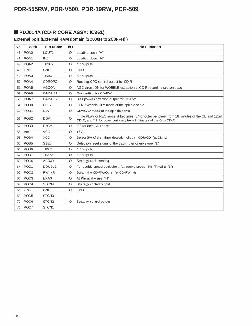
PDJ014A (SERVO DIGITAL ASSY: IC205)External port (External RAM domain (2C000H to 2C0FFH) )
14
PDR-555RW, PDR-V500, PDR-19RW, PDR-509
.oN kraM emaNniP O/I noitcnuFniP
1 6PIF 6DIRG O 5tuptuodirgLF
2 5PIF 5DIRG O 6tuptuodirgLF
3 4PIF 4DIRG O 7tuptuodirgLF
4 3PIF 3DIRG O 8tuptuodirgLF
5 2PIF 2DIRG O 9tuptuodirgLF
6 1PIF 1DIRG O 01tuptuodirgLF
7 0PIF 0DIRG O 11tuptuodirgLF
8 DDV − − DDVottcennoC
9 KOCS − O stuptuo"L"desutoN
01 0OS − O stuptuo"L"desutoN
11 0IS − O stuptuo"L"desutoN
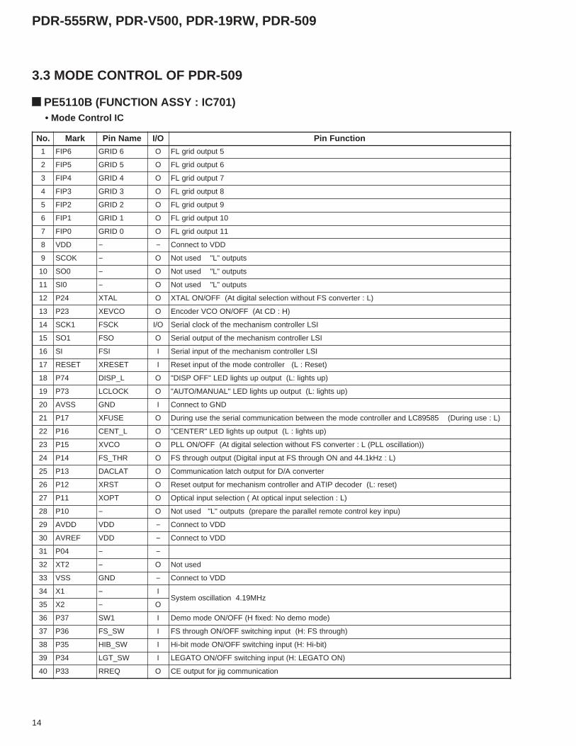
21 42P LATX O )L:retrevnocSFtuohtiwnoitceleslatigidtA(FFO/NOLATX
31 32P OCVEX O )H:DCtA(FFO/NOOCVredocnE
41 1KCS KCSF O/I ISLrellortnocmsinahcemehtfokcolclaireS
51 1OS OSF O ISLrellortnocmsinahcemehtfotuptuolaireS
61 IS ISF I ISLrellortnocmsinahcemehtfotupnilaireS
71 TESER TESERX I )teseR:L(rellortnocedomehtfotupniteseR
81 47P L_PSID O )pusthgil:L(tuptuopusthgilDEL"FFOPSID"
91 37P KCOLCL O )pusthgil:L(tuptuopusthgilDEL"LAUNAM/OTUA"
02 SSVA DNG I DNGottcennoC
12 71P ESUFX O )L:esugniruD(58598CLdnarellortnocedomehtneewtebnoitacinummoclairesehtesugniruD
22 61P L_TNEC O )pusthgil:L(tuptuopusthgilDEL"RETNEC"
32 51P OCVX O ))noitallicsoLLP(L:retrevnocSFtuohtiwnoitceleslatigidtA(FFO/NOLLP
42 41P RHT_SF O )L:zHk1.44dnaNOhguorhtSFtatupnilatigiD(tuptuohguorhtSF
52 31P TALCAD O retrevnocA/DroftuptuohctalnoitacinummoC
62 21P TSRX O )teser:L(redocedPITAdnarellortnocmsinahcemroftuptuoteseR
72 11P TPOX O )L:noitcelestupnilacitpotA(noitcelestupnilacitpO
82 01P − O )upniyeklortnocetomerlellarapehteraperp(stuptuo"L"desutoN
92 DDVA DDV − DDVottcennoC
03 FERVA DDV − DDVottcennoC
13 40P − −
23 2TX − O desutoN
33 SSV DNG − DDVottcennoC
43 1X − IzHM91.4noitallicsometsyS
53 2X − O
63 73P 1WS I )edomomedoN:dexifH(FFO/NOedomomeD
73 63P WS_SF I )hguorhtSF:H(tupnignihctiwsFFO/NOhguorhtSF
83 53P WS_BIH I )tib-iH:H(tupnignihctiwsFFO/NOedomtib-iH
93 43P WS_TGL I )NOOTAGEL:H(tupnignihctiwsFFO/NOOTAGEL
04 33P QERR O noitacinummocgijroftuptuoEC
3.3 MODE CONTROL OF PDR-509
PE5110B (FUNCTION ASSY : IC701) • Mode Control IC
15
PDR-555RW, PDR-V500, PDR-19RW, PDR-509
.oN kraM emaNniP O/I noitcnuFniP
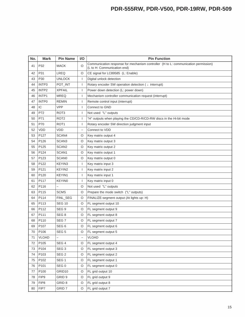
14 23P KCAM O)noissimrepnoitacinummoc:LotH(rellortnocmsinahcemrofesnopsernoitacinummoC
)dnenoitacinummoC:HotL(
24 13P QERL O )elbanE:L(58598CLroflangisEC
34 03P KCOLNU I noitcetedkcolnulatigiD
44 3PTNI TNI_TOP I (noitcetednoitarepoWSredocneyratoR ↓ )tpurretni
54 2PTNI LIAFPX I )nwodrewop:L(noitcetednwodrewoP
64 1PTNI QERM I )tpurretni(tseuqernoitacinummocrellortnocmsinahceM
74 0PTNI NIMER I )tpurretni(tupnilortnocetomeR
84 CI PPV I DNGottcennoC
94 27P 3TOR I stuptuo"L"desutoN
05 17P 2TOR I edomtib-iHehtniscsidWR-DC/R-DC/DCehtgniyalpnehwstuptuo"H"
15 07P 1TOR I tupnitnemgdujnoitceridWSredocneyratoR
25 DDV DDV − DDVottcennoC
35 721P 4NACS O 4tuptuoxirtamyeK
45 621P 3NACS O 3tuptuoxirtamyeK
55 521P 2NACS O 2tuptuoxirtamyeK
65 421P 1NACS O 1tuptuoxirtamyeK
75 321P 0NACS O 0tuptuoxirtamyeK
85 221P 3NIYEK I 3tupnixirtamyeK
95 121P 2NIYEK I 2tupnixirtamyeK
06 021P 1NIYEK I 1tupnixirtamyeK
16 711P 0NIYEK I 0tupnixirtamyeK
26 611P − O stuptuo"L"desutoN
36 511P SMCS O )stuptuo"L"(hctiwsedomehteraperP
46 411P GES_LNIF O )H:pusthgiltA(tuptuotnemges-EZILANIF
56 311P 01GES O 01tuptuotnemgesLF
66 211P 9GES O 9tuptuotnemgesLF
76 111P 8GES O 8tuptuotnemgesLF
86 011P 7GES O 7tuptuotnemgesLF
96 701P 6GES O 6tuptuotnemgesLF
07 601P 5GES O 5tuptuotnemgesLF
17 DAOLV − − DAOLV
27 501P 4GES O 4tuptuotnemgesLF
37 401P 3GES O 3tuptuotnemgesLF
47 301P 2GES O 2tuptuotnemgesLF
57 201P 1GES O 1tuptuotnemgesLF
67 101P 0GES O 0tuptuotnemgesLF
77 001P 01DIRG O 01tuptuodirgLF
87 9PIF 9DIRG O 9tuptuodirgLF
97 8PIF 8DIRG O 8tuptuodirgLF
08 7PIF 7DIRG O 7tuptuodirgLF
16
PDR-555RW, PDR-V500, PDR-19RW, PDR-509
.oN kraM emaNniP O/I noitcnuFniP
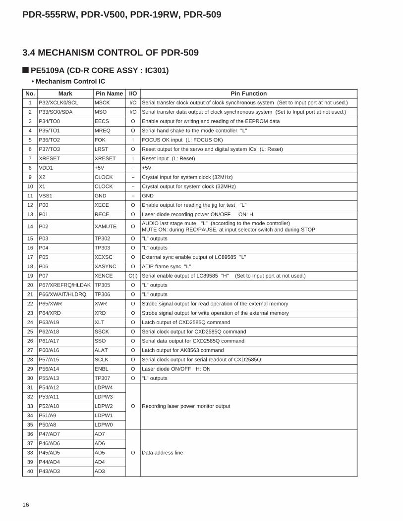
1 LCS/0KLCX/23P KCSM O/I ).desutontatroptupnIotteS(metsyssuonorhcnyskcolcfotuptuokcolcrefsnartlaireS
2 ADS/0OS/33P OSM O/I ).desutontatroptupnIotteS(metsyssuonorhcnyskcolcfotuptuoatadrefsnartlaireS
3 0OT/43P SCEE O atadMORPEEehtfognidaerdnagnitirwroftuptuoelbanE
4 1OT/53P QERM O "L"rellortnocedomehtotekahsdnahlaireS
5 2OT/63P KOF I )KOSUCOF:L(tupniKOSUCOF
6 3OT/73P TSRL O )teseR:L(sCImetsyslatigiddnaovresehtroftuptuoteseR
7 TESERX TESERX I )teseR:L(tupniteseR
8 1DDV V5+ − V5+
9 2X KCOLC − )zHM23(kcolcmetsysroftupnilatsyrC
01 1X KCOLC − )zHM23(kcolcmetsysroftuptuolatsyrC
11 1SSV DNG − DNG
21 00P ECEX O "L"tsetrofgijehtgnidaerroftuptuoelbanE
31 10P ECER O H:NOFFO/NOrewopgnidroceredoidresaL
41 20P ETUMAX O)rellortnocedomehtotgnidrocca("L"etumegatstsalOIDUA
POTSgniruddnahctiwsrotcelestupnita,ESUAP/CERgnirud:NOETUM
51 30P 203PT O stuptuo"L"
61 40P 303PT O stuptuo"L"
71 50P CSXEX O "L"58598CLfotuptuoelbanecnyslanretxE
81 60P CNYSAX O "L"cnysemarfPITA
91 70P ECNEX )I(O ).desutontatroptupnIotteS("H"58598CLfotuptuoelbanelaireS
02 KADLH/QRFERX/76P 503PT O stuptuo"L"
12 QRDLH/TIAWX/66P 603PT O stuptuo"L"
22 RWX/56P RWX O yromemlanretxeehtfonoitarepodaerroftuptuolangisebortS
32 DRX/46P DRX O yromemlanretxeehtfonoitarepoetirwroftuptuolangisebortS
42 91A/36P TLX O dnammocQ5852DXCfotuptuohctaL
52 81A/26P KCSS O dnammocQ5852DXCroftuptuokcolclaireS
62 71A/16P OSS O dnammocQ5852DXCroftuptuoatadlaireS
72 61A/06P TALA O dnammoc3658KAroftuptuohctaL
82 51A/75P KLCS O Q5852DXCfotuodaerlairesroftuptuokcolclaireS
92 41A/65P LBNE O NO:HFFO/NOedoidresaL
03 31A/55P 703PT O stuptuo"L"
13 21A/45P 4WPDL
O tuptuorotinomrewopresalgnidroceR
23 11A/35P 3WPDL
33 01A/25P 2WPDL
43 9A/15P 1WPDL
53 8A/05P 0WPDL
63 7DA/74P 7DA
O enilsserddaataD
73 6DA/64P 6DA
83 5DA/54P 5DA
93 4DA/44P 4DA
04 3DA/34P 3DA
3.4 MECHANISM CONTROL OF PDR-509
PE5109A (CD-R CORE ASSY : IC301) • Mechanism Control IC
17
PDR-555RW, PDR-V500, PDR-19RW, PDR-509
.oN kraM emaNniP O/I noitcnuFniP
14 2DA/24P 2DA
O enilsserddaataD24 1DA/14P 1DA
34 0DA/04P 0DA
44 TUOKLC/BTSA BTSA O sseccayromemlanretxeroflangissserddarewolfolangishctallanretxE
54 0ssV DNG − DNG
64 TSET DNG − DNG
74 0MWP/01P PSPS )A(O VACeldnipSehtnituptuoMWPevirdeldnipS
84 1MWP/11P MWPL )A(O )"H"otdexif("H":desutonsiMWPTA)MWP(tuptuorotomgnidaoL
94 2KCSX/2KCSA/21P KCQS O Q5852DXCfoQ-busroftuptuokcolclaireS
05 2IS/2DXR/31P ISQS I Q5852DXCfoQ-busroftupniatadlaireS
15 2OS/2DXT/41P 2OS O tuptuoatadlaireS
25 51P 413PT O stuptuo"L"
35 61P 513PT O stuptuo"L"
45 71P 613PT O stuptuo"L"
55 0DDV V5+ − V5+
65 0INA/07P PPET )A(I )tnemtsujdaniaggnikcartrof(kaepotkaeprorregnikcarT
75 1INA/17P TFR )A(I FRkcabyalPfoepolevneedisreppufotupniD/A
85 2INA/27P BFR )A(I FRkcabyalPfoepolevneedisrewolfotupniD/A
95 3INA/37P PMET )A(I rosneserutarepmetfotupniD/A
06 4INA/47P CPOFR )A(I 1thgilnruterCPOgninnuR
16 5INA/57P 2CDWV )A(I 2thgilnruterCPOgninnuR
26 6INA/67P YART )A(I )PMALC/NEPO(noitisopgnidaolfotupniD/A
36 7INA/77P 7DA )A(I desutoN
46 DDVA ddvA − V5+
56 1FERVA 1fervA − V5+
66 SSVA ssVA − DNG
76 0ONA FERW )A(O 1rewopgnidroceR
86 1ONA R2CDWV )A(O gnittesygetartsrofstuptuO
96 2FERVA 2ferVA − V5+
07 3FERVA 3ferVA − DNG
17 IMN/02P LIAFPX I noitcetederuliafrewoP
27 0PTNI/12P GF I noitcetedGFeldnipS
37 1PTNI/22P PITA I noitcetedCNYSPITA
47 1C/2PTNI/32P ROCS I noitcetedcnysemarfredocedMFE
57 3PTNI/42P CNYSBUS I noitcetedcnysemarfredocedMFE
67-/KCSA/4PTNI/52P
1KCSXTDFRX I noitcetedFRkcabyalpMFE
77 5PTNI/62P NI5TI I tupniSNES
87 0IS/72P ISM I metsys.cnyskcolcehtfotupniATADrefsnartlaireS
97 1IS/DXR/03P KCAM I rellortnocedomehtottupniKCOLCekahsdnahlaireS
08 1OS/DXT/13P ESUFX I rellortnocedomehthtiwetacinummocgnirud"L"
."GOLANA"swohsO/Imetini)A(:etoN
18
PDR-555RW, PDR-V500, PDR-19RW, PDR-509
.oN kraM emaNniP O/I noitcnuFniP
54 0AOP 1TUOL O "H"nepognidaoL
64 1AOP 1NI O "H"esolcgnidaoL
74 2AOP 663PT O stuptuo"L"
84 DNG DNG O DNG
94 3AOP 763PT O stuptuo"L"
05 4AOP CPORDC O R-DCroftuptuolortnocCPOgninnuR
15 5AOP NOCGA O ecartnoitcesgnidrocerR-DCtanoitcartxeELBBOWrofNOtiucricCGA
25 6AOP 1PUNIAG O WR-DCrofgnittesniaG
35 7AOP 2PUNIAG O WR-DCroftuptuonoitcerrocrewopsaiB
45 0BOP VLCE O ovreseldnipsehtfoedomVLCelbboW/MFE
55 1BOP VLC O ovreseldnipsehtfoedomVAC/VLC
65 2BOP IAGD Omc21dnaDCehtfosetunim81morfyrehpirepretuorof"L"semocebti,edomCERroYALPehtnI
.R-DCmc8ehtfosetunim9morfyrehpirepretuorof"H"dna,R-DC
75 3BOP MC8D O csidR-DCmc8rof"H"
85 ccV CCV O V5+
95 4BOP DCX O )L:DCta(DC/RDCtiucricnoitcetedrorrimehtfoWStceleS
06 5BOP LESS O "L"epolevnerorregnikcartehtfolangistesernoitceteD
16 6BOP 173PT O stuptuo"L"
26 7BOP 273PT O stuptuo"L"
36 0COP 03DDA O gnittestsissaygetartS
46 1COP ELBUOD O )"L"otdexiF()H:deeps-elbuodta(tnelaviuqedeeps-elbuodroF
56 2COP RX_WR O )H:WR-DCta(rehtO/WR-DCehthctiwS
66 3COP SARE O "H":esarelacisyhPtA
76 4COP 4NCTS O tuptuolortnocygetartS
86 DNG DNG O DNG
96 5COP 3NCTS
O tuptuolortnocygetartS07 6COP 2NCTS
17 7COP 1NCTS
PDJ014A (CD-R CORE ASSY: IC351)External port (External RAM domain (2C000H to 2C0FFH) )

19
PDR-555RW, PDR-V500, PDR-19RW, PDR-509
4. PIN FUNCTION OF PRINCIPAL IC
4.1 AD1893JSTPDR-555RW, PDR-V500 and PDR-19RW (SERVO DIGITAL ASSY : IC311)PDR-509 (CD-R CORE ASSY : IC502)• Sample Rate Converter IC
.oN emaNniP O/I noitcnuFniP .oN emaNniP O/I noitcnuFniP
1 C/N − desutoN 32 C/N − desutoN
2 I_KLCB I atadtupnirofkcolctiB 42 O_0EDOM I troptuptuoroflortnoc0edomlaireS
3 I_KLCW I atadtupnirofkcolcdroW 52 O_LOPKB I edomlamroN:LytiralopkcolctiB
4 I_RL I atadtupnirofkcolcR/L 62 C/N − desutoN
5 C/N − desutoN 72 DNG − dnuorG
6 DDV − ylppusrewoP 82 DDV − ylppusrewoP
7 DNG − dnuorG 92 C/N − desutoN
8 C/N − desutoN 03 O_ATAD O tsafBSM,tuptuolaireS
9 I_LOPKB I edomlamroN:LytiralopkcolctiB 13 O_RL O atadtuptuorofkcolcR/L
01 I_0EDOM I troptupniroflortnoc0edomlaireS 23 O_KLCW O atadtuptuorofkcolcdroW
11 C/N − desutoN 33 C/N − desutoN
21 C/N − desutoN 43 C/N − desutoN
31 I_1EDOM I troptupniroflortnoc1edomlaireS 53 O_KLCB O atadtuptuorofkcolctiB
41 TESERX I teseR:LlangisteseR 63 NWDRWP ItupninwodrewoP
etatsrewopcirtcelenoitpmusnocwoL:H
51 C/N − desutoN 73 C/N − desutoN
61 DNG − dnuorG 83 WLSTES IgnilpmasehtniegnahcehttsniagagniltteS
tsaF:L,wolS:Hetar
71 C/N − desutoN 93 C/N − desutoN
81 I_ETUM I tupnietuM 04 O_LATX O tuptuolatsyrC
91 C/N − desutoN 14 C/N − desutoN
02 O_ETUM O tuptuoetuM 24 I_LATX I tupnilatsyrC
12 O_1EDOM I troptuptuoroflortnoc1edomlaireS 34 I_ATAD I tsafBSM,tupnilaireS
22 C/N − desutoN 44 C/N − desutoN
.oN emaNniP O/I noitcnuFniP
1 CN − noitcennocnoN
2 CCV − ylppusrewoP
3 SC I tupnitcelespihC
4 KS I tupnikcolclaireS
5 ID I tupniatadlairesdnasserdda,edocnoitarepo,tibtratS
6 OD O etatslanretniYSUBX/YDAERfotuptuonoitacidnidnatuptuoatadlaireS
7 DNG − dnuorG
8 CN − noitcennocnoN
4.2 PYY1196PDR-555RW, PDR-V500 and PDR-19RW (FUNCTION ASSY : IC705)PDR-509 (CD-R CORE ASSY : IC303)• EEPROM
• The information shown in the list is basic information and may not correspond exactly to that shown in the schematic diagrams.
20
PDR-555RW, PDR-V500, PDR-19RW, PDR-509
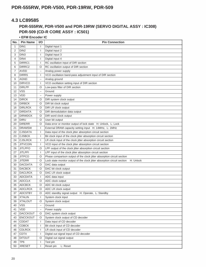
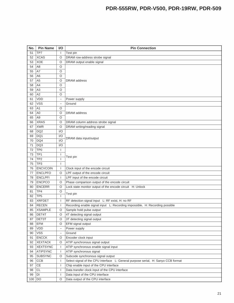
4.3 LC89585PDR-555RW, PDR-V500 and PDR-19RW (SERVO DIGITAL ASSY : IC308)PDR-509 (CD-R CORE ASSY : IC501)• EFM Encoder IC
.oN emaNniP O/I noitcennoCniP1 1NID I 1tupnilatigiD
2 2NID I 2tupnilatigiD
3 3NID I 3tupnilatigiD
4 4NID I 4tupnilatigiD
5 1CRRID I noitcesRIDfotupninoitallicsoCR
6 2CRRID O noitcesRIDfotuptuonoitallicsoCR
7 DDVA − ylppusrewopgolanA
8 SRRID I noitcesRIDfotupnitnemtsujdassap-dnabnoitallicsoOCV
9 DNGA − dnuorggolanA
01 OCVRID I noitcesRIDfotupnignittesnoitallicsoOCV
11 FPLRID O noitcesRIDforetlifssap-woL
21 SSV − dnuorG
31 DDV − ylppusrewoP
41 KCRID O tuptuokcolcmetsysRID
51 KCBRID O tuptuokcolctibRID
61 KCRLRID O tuptuokcolcRLRID
71 ATADRID O tuptuoatadnoitaludomedRID
81 KCDWRID O tuptuokcolcdrowRID
91 URID O tuptuotibresU
02 RRERID O kcoL:L,kcolnU:HetatskcolfotuptuorotinomrororreataD
12 WSMARD I zHM1:L,zHM41:HtupnignittesyticapacMARDlanretxE
22 ATADSJC I noitcestiucricnoitprosbarettijkcolcehtfotupniataD
32 KCBSJC I noitcestiucricnoitprosbarettijkcolcehtfotupnikcolctiB
42 KCRLSJC I noitcestiucricnoitprosbarettijkcolcehtfotupnikcolcRL
52 NIOCVTIJ I noitcestiucricnoitprosbarettijkcolcehtfotupniOCV
62 OFPLTIJ O noitcestiucricnoitprosbarettijkcolcehtfotuptuoFPL
72 IFPLTIJ I noitcestiucricnoitprosbarettijkcolcehtfotupniFPL
82 OCPTIJ O noitcestiucricnoitprosbarettijkcolcehtfotuptuonosirapmocesahP
92 RRETIJ O kcolnU:HnoitcestiucricnoitprosbarettijkcolcehtfotuptuorotinometatskcoL
03 ATADCAD O tuptuoatadCAD
13 KCBCAD O tuptuokcolctibCAD
23 KCRLCAD O tuptuokcolcRLCAD
33 ATADCDA I tupniatadCDA
43 KLCCDA O tuptuokcolcCDA
53 KCBCDA O tuptuokcolctibCDA
63 KCRLCDA O tuptuokcolcRLCDA
73 YBTSCDA O ybdnatS:L,etarepO:HtuptuolangisybdnatsCDA
83 NILATX I tupnikcolcmetsyS
93 TUOLATX O tuptuokcolcmetsyS
04 SSV − dnuorG
14 DDV − ylppusrewoP
24 TUOKCCAD O tuptuokcolcmetsysCAD
34 TUOKCCNE O redocedDCfotuptuokcolcmetsyS
44 TADDC I redocedDCfotupniataD
54 KCBDC I redocedDCfotupnikcolctiB
64 KCRLDC I redocedDCfotupnikcolcRL
74 XTDC I redocedDCfotupnilangistuolatigiD
84 TUOTID O tuptuolangistuolatigiD
94 6PT I niptseT
05 TESERX I teseR:LnipteseR
21
PDR-555RW, PDR-V500, PDR-19RW, PDR-509
.oN emaNniP O/I noitcennoCniP15 7PT I niptseT
25 SACX O langisebortssserdda-worMARD
35 EOX O langiselbanetuptuoMARD
45 8A O
sserddaMARD
55 7A O
65 6A O
75 5A O
85 4A O
95 3A O
06 2A O
16 DDV − ylppusrewoP
26 SSV − dnuorG
36 1A O
sserddaMARD46 0A O
56 9A O
66 SARX O langisebortssserddanmulocMARD
76 RWX O langisgnidaer/gnitirwMARD
86 2QD O/I
tuptuo/tupniatadMARD96 1QD O/I
07 4QD O/I
17 3QD O/I
27 0PT I
niptseT37 1PT I
47 2PT I
57 3PT I
67 NIOCVCNE I tiucricedocneehtfotupnikcolC
77 OFPLCNE O tiucricedocneehtfotuptuoFPL
87 IFPLCNE I tiucricedocneehtfotupniFPL
97 OCPCNE O tiucricedocneehtfotuptuonosirapmocesahP
08 RRECNE O kcolnU:HtiucricedocneehtfotuptuorotinometatskcoL
18 4PT OniptseT
28 5PT I
38 TEDFRX I FRon:H,tsixeFR:LtupnilangisnoitcetedFR
48 NECER I elbissopgnidroceR:H,elbissopmignidroceR:LtupnilangiselbanegnidroceR
58 ELPMASX O tuptuoeslupdlohelpmaS
68 T4TED O tuptuolangisgnitcetedT4
78 T3TED O tuptuolangisgnitcetedT3
88 MFE O tuptuolangisMFE
98 DDV − ylppusrewoP
09 SSV − dnuorG
19 KCCNE O tupnikcolcredocnE
29 KCATXEX O tuptuolangissuonorhcnysPITA
39 CNYSTXEX I tupnilangiselbanesuonorhcnysPITA
49 CNYSPITA I langissuonorhcnysPITA
59 CNYSBUS O tuptuolangissuonorhcnysedocbuS
69 BCC I tamrofBCCoynaS:H,lairesesopruplareneG:LecafretniUPCehtfolangistceleS
79 EC I ecafretniUPCehtfotupnielbanepihC
89 LC I ecafretniUPCehtfotupnikcolcrefsnartataD
99 ID I ecafretniUPCehtfotupniataD
001 OD O ecafretniUPCehtfotuptuoataD
22
PDR-555RW, PDR-V500, PDR-19RW, PDR-509
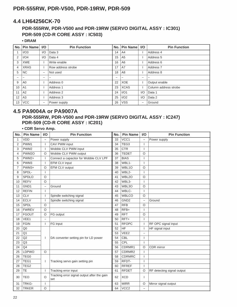
4.4 LH64256CK-70PDR-555RW, PDR-V500 and PDR-19RW (SERVO DIGITAL ASSY : IC301)PDR-509 (CD-R CORE ASSY : IC503)• DRAM
4.5 PA9004A or PA9007APDR-555RW, PDR-V500 and PDR-19RW (SERVO DIGITAL ASSY : IC247)PDR-509 (CD-R CORE ASSY : IC201)• CDR Servo Amp.
.oN emaNniP O/I noitcnuFniP .oN emaNniP O/I noitcnuFniP1 3O/I O/I 3ataD 41 4A I 4sserddA
2 4O/I O/I 4ataD 51 5A I 5sserddA
3 EWX I elbaneetirW 61 6A I 6sserddA
4 SARX I ebortssserddawoR 71 7A I 7sserddA
5 CN − desutoN 81 8A I 8sserddA
− − − − − − − −9 0A I 0sserddA 22 EOX I elbanetuptuO
01 1A I 1sserddA 32 SACX I ebortssserddanmuloC
11 2A I 2sserddA 42 1O/I O/I 1ataD
21 3A I 3sserddA 52 2O/I O/I 2ataD
31 CCV − ylppusrewoP 62 SSV − dnuorG
.oN emaNniP O/I noitcnuFniP .oN emaNniP O/I noitcnuFniP1 DDV − ylppusrewoP 33 1CCV − ylppusrewoP
2 1MWP I tupniMWPVAC 43 3GET I
3 2MWP I tupniMWPVLCelbboW 53 RTC I
4 O2MWP O tuptuoMWPVLCelbboW 63 TEDET O
5 +2MWP I FPLVLCelbboWrofroticapacatcennoC 73 SAIB I
6 3MWP I tupniVLCMFE 83 -1LBW I
7 +3MWP O tuptuoVLCMFE 93 O1LBW O
8 -LDPS I 04 -2LBW I
9 OLDPS O 14 O2LBW O
01 VFER O 24 -3LBW I
11 1DNG − dnuorG 34 O3LBW O
21 NIFER I 44 -CLBW I
31 VLC I langisgnihctiwseldnipS 54 OCLBW O
41 VLCE I langisgnihctiwseldnipS 64 2DNG − dnuorG
51 LDPS O 74 BFR O
61 VERWF O 84 +BFR I
71 TUOGF O tuptuoGF 94 TFR O
81 1EEV − 05 +TFR I
91 NIGF I tupniGF 15 CPOFR I tupnilangisCPOFR
02 0Q
I rewopDLrofnipgnittesretrevnocAD
25 FH I tupnilangisFH
12 1Q 35 2EEV −22 2Q 45 LBC I
32 3Q 55 LPC I
42 4Q 65 1RMRDC O rorrimRDC
52 OWPDL O 75 2RMRDC I
62 0GET
I nipgnittesniagovresgnikcarT
85 CRMRDC I
72 1GET 95 -TDFR I
82 2GET 06 FERFR I
92 ET I tupnirorregnikcarT 16 TEDFR O tuptuolangisgnitcetedFR
03 OET OniagehtretfatuptuolangisrorregnikcarT
tes26 DCX I
13 -GKRT I 36 RRIM O tuptuolangisrorriM
23 REKRT O 46 2CCV −

23
PDR-555RW, PDR-V500, PDR-19RW, PDR-509
4.6 PDJ014APDR-555RW, PDR-V500 and PDR-19RW (SERVO DIGITAL ASSY : IC205)PDR-509 (CD-R CORE ASSY : IC351)• ATIP Decoder
.oN emaNniP O/I noitcnuFniP .oN emaNniP O/I noitcnuFniP1 LBW I tupnielbboW 14 0ECX O 0tuptuoelbanepihC
2 KSF O tuptuolangisnoitaludomedKSF 24 1ECX O 1tuptuoelbanepihC
3 YSBS I zH57:yllamroNtupni.cnysedocbuS 34 2ECX O 2tuptuoelbanepihC
4 PDM O ovresVLCroftuptuoPDM 44 3ECX O 3tuptuoelbanepihC
5 LESPS I lellaraP:L,laireS:HtcelesecafretniUPC 54 0AOP O/Ituptuo/tupniesopruplareneG
)H:WR-DC(WR-DCrofhctiwsniaG
6 CNYSA O tuptuo.cnysPITA 64 1AOP O/ItiucricCAtuptuo/tupniesopruplareneG
CPOgninnurR-DCroflangislortnoc7 KCA I tupnikcolcecafretnilaireS 74 2AOP O/I tuptuo/tupniesopruplareneG
8 DNG − dnuorG 84 DNG − dnuorG
9 EPTUOA I elbanedaeratadlaireS 94 3AOP O/Itupni4INAtuptuo/tupniesopruplareneG
)TUOXPM:L,CPOFR:H(hctiws
01 TUOA O stib23tuptuoatadlaireS 05 4AOP O/Ituptuo/tupniesopruplareneG
esarElacisyhP
11 EPNIA I tupnielbaneetirwatadlaireS 15 5AOP O/IteseRtuptuo/tupniesopruplareneG
noitcetedepolevnerorregnikcartfolangis
21 NIA I stib61tupniatadlaireS 25 6AOP O/ItiucricCGAtuptuo/tupniesopruplareneG
noitcartxeelbboWrofFFO/NO
31 KCX ItupnikcolcretsaM
zHM8123.4:deepslamroN35 7AOP O/I
tuptuo/tupniesopruplareneGpmujkcartN
41 TSRSX I teser:LtesermetsyS 45 0BOP O nepognidaoLtuptuoesopruplareneG
51 KOIS OtuptuogalfybdnatsnoitamrofnilaicepS
elbissoptuodaeR:H55 1BOP O esolcgnidaoLtuptuoesopruplareneG
61 KOCRC OtuptuotlusernoitaluclacCRC
GNCRC:L,KOCRC:H65 2BOP O
tuptuoesopruplareneGFFO/NOtiucricgnihctiwssixalacitpO
71 TCETORP Otuptuoetatsnoitcetorp.cnysPITA
noitcetorp-noN:L,noitcetorP:H75 3BOP O
roftuptuoelbanEtuptuoesopruplareneGatadMORPEEehtgnidaerdnagnitirw
81 CCV − ylppusrewoP 85 CCV − ylppusrewoP
91 CN − desutoN 95 4BOP O
tuptuoesopruplareneGtuptuolortnocygetartS
02 LESDAX IsserddafotupniebortsgnittessserddatratS
redoced06 5BOP O
12 EWX I retupmocorcimehtfotupnielbaneetirW 16 6BOP O
22 ERX I retupmocorcimehtfotupnielbanedaeR 26 7BOP O
32 0AYS I
retupmocorcimehtfosubsserddA
36 0COP OtuptuoesopruplareneG
tnemtsujdaniagpmarorregnikcarT42 1AYS I 46 1COP O
52 2AYS I 56 2COP O
62 3AYS I 66 3COP OtuptuoesopruplareneGrehto/WR-DCehthctiwS
72 21AYS I 76 4COP O desutoNtuptuoesopruplareneG
82 DNG − dnuorG 86 DNG − dnuorG
92 31AYS I
retupmocorcimehtfosubsserddA
96 5COP OtuptuoesopruplareneG
rehto/DCehthctiwS
03 41AYS I 07 6COP OtuptuoesopruplareneG
tuptuoFFO/NODL
13 51AYS I 17 7COP OtuptuoesopruplareneG
etumegatstsaloiduA23 0DYS O/I
retupmocorcimehtfosubataD
27 BTSET I niptseT
33 1DYS O/I 37 TSET I niptseT
43 2DYS O/I 47 0TSET I niptseT
53 3DYS O/I 57 1TSET I niptseT
63 4DYS O/I 67 2TSET I niptseT
73 5DYS O/I 77 3TSET I niptseT
83 CCV − ylppusrewoP 87 CCV − ylppusrewoP
93 6DYS O/IretupmocorcimehtfosubataD
97 4TSET I niptseT
04 7DYS O/I 08 HTSP_LERP I

24
PDR-555RW, PDR-V500, PDR-19RW, PDR-509
4.7 PDK033A [ PDR-555RW, PDR-V500 and PDR-19RW (SERVO DIGITAL ASSY : IC316)]PDK041A [ PDR-509 (CD-R CORE ASSY : IC431)]• Strategy Control IC
.oN emaNniP O/I noitcnuFniP .oN emaNniP O/I noitcnuFniP1 CN − desutoN 52 NODO O NOevird-revo:Hlortnocevird-revO
2 TESERX I teseR:LteseR 62 CN − desutoN
3 CN − desutoN 72 RX_W O gnitirw:Htuptuolangisgnidaer/gnitirW
4 M43KC I tupnikcolC 82 CN − desutoN
5 CN − desutoN 92 NODLW O lortnocDLetirW
6 M71KC O M71KCfotuptuognidivid2 03 DDV − ylppusrewoP
7 CN − desutoN 13 DNG − dnuorG
8 HSDPFW O CPAetirWroftuptuoeslupelpmaS 23 NODLWR O FFO/NODLWR-DC
9 CN − desutoN 33 CN − desutoN
01 ELPMAS O tuptuoeslupdlohelpmaS 43 NODLWER O WR-DC/R-DC,DCehthctiwS
11 CN − desutoN 53 CN − desutoN
21 HSCPO O CPOroftuptuoeslupdlohelpmaS 63 CN − desutoN
31 CN − desutoN 73 1NCTS I 1tcelesygetaratS
41 CN − desutoN 83 2NCTS I 2tcelesygetaratS
51 M4KC I tupnizHM8123.4 93 3NCTS I 3tcelesygetaratS
61 CN − desutoN 04 4NCTS I 4tcelesygetaratS
71 NIMFE I tupniMFE 14 CN − desutoN
81 CN − desutoN 24 ESARE I lortnocESARE
91 ELPMASX I tupnieslupdlohelpmaS 34 CN − desutoN
02 CN − desutoN 44 RX_WR I WR-DC/R-DCehthctiwS
12 ECER I tupnilangiselbanegnidroceR 54 CN − desutoN
22 CN − desutoN 64 ELBUOD I deepselbuod/deepslamronehthctiwS
32 1TST I dnuorgottcennoCniptseT 74 CN − desutoN
42 CN − desutoN 84 03DDA ItnemtsujdaygetartsrofstuptuO
)03+yaledT3(

25
PDR-555RW, PDR-V500, PDR-19RW, PDR-509
.oN emaNniP O/I noitcnuFniP1 +LNIA I tupnignitrevni-nongolanahcL
2 -LNIA I tupniesahp-evitisopgolanahcL
3 NIFERV I tupniegatlovecnerefeR
4 +AV − ylppusrewopgolanA
5 DNGA − dnuorggolanA
6 CN − desutoN
7 CN − desutoN
8 1TST − niptseT
9 81LES I stib81:H,stib61:LtceleshtgnelatadtuptuO
01 DP I nwodrewoP:HnwodrewoP
11 2TST − niptseT
21 EDOMC I sf483:H,sf652:LtceleskcolcretsaM
31 EDOMS I edomretsaM:H,edomevalS:LtceleskcolcecafretnI
41 RX/L I tupnikcolcRL
51 KLCS I tupnikcolcatadlaireS
61 ATADS O tuptuoatadlaireS
71 CNYSF I elbanE:HATADSfoelbanetuptuO
81 +PDV − ylppusrewoplatigiD
91 DNGD − dnuorglatigiD
02 KLC I tupnikcolcretsaM
12 3TST − niptseT
22 4TST − niptseT
32 CN − desutoN
42 +BDV − ylppusrewoplatigiD
52 CN − desutoN
62 FERV O V6.2–)+AV(tuptuoegatlovecnerefeR
72 -RNIA I tupnignitrevni-nongolanahcR
82 +RNIA I tupniesahp-evitisopgolanahcR
4.8 AK5340-VSPDR-555RW, PDR-V500 and PDR-19RW only (AUDIO ASSY : IC801)• A/D Converter IC
26
PDR-555RW, PDR-V500, PDR-19RW, PDR-509
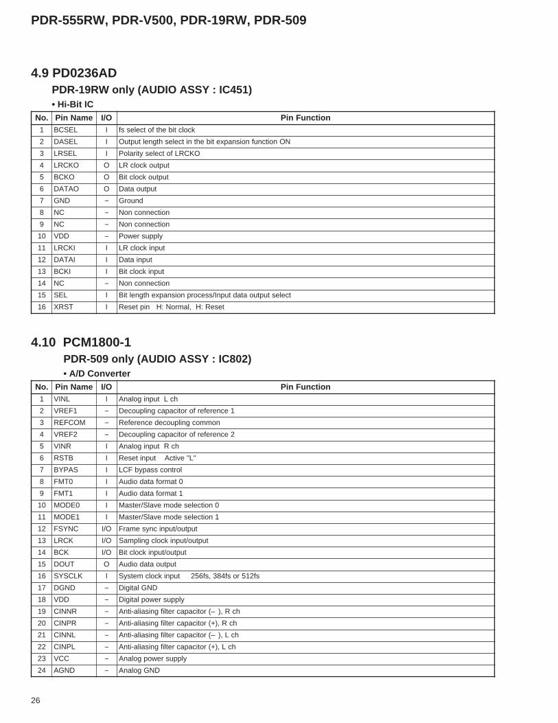
4.9 PD0236ADPDR-19RW only (AUDIO ASSY : IC451)• Hi-Bit IC
4.10 PCM1800-1PDR-509 only (AUDIO ASSY : IC802)• A/D Converter
.oN emaNniP O/I noitcnuFniP1 LESCB I kcolctibehtfotcelessf
2 LESAD I NOnoitcnufnoisnapxetibehtnitceleshtgneltuptuO
3 LESRL I OKCRLfotcelesytiraloP
4 OKCRL O tuptuokcolcRL
5 OKCB O tuptuokcolctiB
6 OATAD O tuptuoataD
7 DNG − dnuorG
8 CN − noitcennocnoN
9 CN − noitcennocnoN
01 DDV − ylppusrewoP
11 IKCRL I tupnikcolcRL
21 IATAD I tupniataD
31 IKCB I tupnikcolctiB
41 CN − noitcennocnoN
51 LES I tcelestuptuoatadtupnI/ssecorpnoisnapxehtgneltiB
61 TSRX I teseR:H,lamroN:HnipteseR
.oN emaNniP O/I noitcnuFniP1 LNIV I hcLtupnigolanA
2 1FERV − 1ecnereferforoticapacgnilpuoceD
3 MOCFER − nommocgnilpuocedecnerefeR
4 2FERV − 2ecnereferforoticapacgnilpuoceD
5 RNIV I hcRtupnigolanA
6 BTSR I "L"evitcAtupniteseR
7 SAPYB I lortnocssapybFCL
8 0TMF I 0tamrofatadoiduA
9 1TMF I 1tamrofatadoiduA
01 0EDOM I 0noitcelesedomevalS/retsaM
11 1EDOM I 1noitcelesedomevalS/retsaM
21 CNYSF O/I tuptuo/tupnicnysemarF
31 KCRL O/I tuptuo/tupnikcolcgnilpmaS
41 KCB O/I tuptuo/tupnikcolctiB
51 TUOD O tuptuoatadoiduA
61 KLCSYS I sf215rosf483,sf652tupnikcolcmetsyS
71 DNGD − DNGlatigiD
81 DDV − ylppusrewoplatigiD
91 RNNIC − hcR,)–(roticapacretlifgnisaila-itnA
02 RPNIC − hcR,)+(roticapacretlifgnisaila-itnA
12 LNNIC − hcL,)–(roticapacretlifgnisaila-itnA
22 LPNIC − hcL,)+(roticapacretlifgnisaila-itnA
32 CCV − ylppusrewopgolanA
42 DNGA − DNGgolanA
27
PDR-555RW, PDR-V500, PDR-19RW, PDR-509
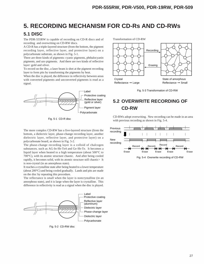
5.1 DISCThe PDR-555RW is capable of recording on CD-R discs and ofrecording and overwriting on CD-RW discs.A CD-R has a triple-layered structure (from the bottom, the pigmentrecording layer, reflective layer, and protective layer) on apolycarbonate substrate, as shown in Fig. 5-1.There are three kinds of pigments: cyanic pigments, phthalocyaninpigments, and azo pigments. And there are two kinds of reflectivelayer: gold and silver.To record on the disc, a laser beam is shot at the pigment recordinglayer to form pits by transforming the pigments by heat.When the disc is played, the difference in reflectivity between areaswith converted pigments and unconverted pigments is read as asignal.
The more complex CD-RW has a five-layered structure (from thebottom, a dielectric layer, phase-change recording layer, anotherdielectric layer, reflective layer, and protective layer) on apolycarbonate board, as shown in Fig. 5-2.The phase-change recording layer is a colloid of chalcogensubstances. such as AG-In-Sb-Te4 and Ge-Sb-Te. It becomes aliquid layer when heated to a high temperature (about 500°C to700°C), with its atomic structure chaotic. And after being cooledrapidly, it becomes solid, with its atomic structure still chaotic> Itis non-crystal (in an amorphous state).It reaches a crystalline state after being heated to a lower temperature(about 200°C) and being cooled gradually. Lands and pits are madeon the disc by repeating this procedure.The reflectance is small when the layer is noncrystalline (in anamorphous state), and it is large when the layer is crystalline. Thisdifference in reflectivity is read as a signal when the disc is played.
Transformation of CD-RW
CD-RWs adopt overwriting. New recording can be made in an areawith previous recording as shown in Fig. 5-4.
Reflective layer(gold or silver)
Pigment layer
Polycarbonate
Fig. 5-1 CD-R disc
Protective coating
Label
Reflective layer(aluminum)
Dielectric layer
Dielectric layer
Phase-change layer
Polycarbonate
Fig. 5-2 CD-RW disc
Protective coatingLabel
Recording
Erasing
State of amorphousCrystalReflectance = Large Reflectance = Small
Fig. 5-3 Transformation of CD-RW
Previousrecording
Newrecording
Record Record
Fig. 5-4 Overwrite recording of CD-RW
Record Record
EraseEraseEraseEraseErase
5.2 OVERWRITE RECORDING OF
CD-RW
5. RECORDING MECHANISM FOR CD-Rs AND CD-RWs
28
PDR-555RW, PDR-V500, PDR-19RW, PDR-509
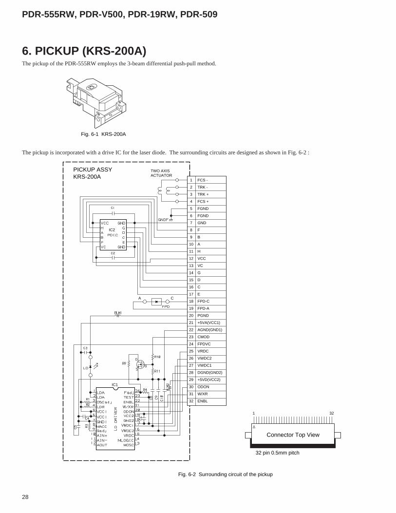
The pickup is incorporated with a drive IC for the laser diode. The surrounding circuits are designed as shown in Fig. 6-2 :
TWO AXISACTUATOR
IC2
IC1
A C
1
2
3
4
5
6
7
8
9
10
11
12
13
14
15
16
17
18
19
20
21
22
23
24
25
26
27
28
29
30
31
32
FCS -
TRK -
TRK +
FCS +
FGND
FGND
GND
F
B
A
H
VCC
VC
G
D
C
E
FPD-C
FPD-A
PGND
+5VA(VCC1)
AGND(GND1)
CMOD
FPDVC
VRDC
VWDC2
VWDC1
DGND(GND2)
+5VD(VCC2)
ODON
W/XR
ENBL
1
Connector Top View
32 pin 0.5mm pitch
32
PICKUP ASSYKRS-200A
Fig. 6-2 Surrounding circuit of the pickup
6. PICKUP (KRS-200A)The pickup of the PDR-555RW employs the 3-beam differential push-pull method.
Fig. 6-1 KRS-200A
29
PDR-555RW, PDR-V500, PDR-19RW, PDR-509
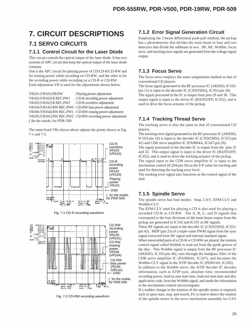
7. CIRCUIT DESCRIPTIONS7.1 SERVO CIRCUITS7.1.1 Control Circuit for the Laser DiodeThis circuit controls the optical output of the laser diode. It has twosystems of APC circuit that keep the optical output of the laser diodeconstant.One is the APC circuit for playing power of CD/CD-R/CD-RW andfor erasing power while recording on CD-RW, and the other is forthe recording power while recording on a CD-R or CD-RW.Each adjustment VR is used for the adjustments shown below.
VR101 (VR101) PB.PW : Playing power adjustmentVR102 (VR163) R REC.PW1 : CD-R recording power adjustmentVR103 (VR162) R REC.PW2 : CD-R overdrive adjustmentVR104 (VR141) RW REC.PW0 : CD-RW bias power adjustmentVR106 (VR164) RW REC.PW1 : CD-RW erasing power adjustmentVR105 (VR161) RW REC.PW2 : CD-RW recording power adjustment( )In the inside, for PDR-509.
The semi-fixed VRs shown above adjusts the points shown in Fig.7-1 and 7-2.
GND
GND
PlayingpowerVR101
CD-RrecordingpowerVR102(VR163)
CD-RoverdriveVR103(VR162)
CD-RWbias powerVR104(VR141)
CD-RWerasingpowerVR106(VR164)
CD-RWrecordingpowerVR105(VR161)
Fig. 7-1 CD-R recording waveform
Fig. 7-2 CD-RW recording waveform
( )In the inside, for PDR-509.
( )In the inside, for PDR-509.
7.1.2 Error Signal Generation CircuitEmploying the 3-beam differential push-pull method, the pickuphas a photodetector that divides the main beam in four and twodetectors that divide the subbeam in two. HF, RF, Wobble, focuserror, and tracking error signals are generated from the voltage signaloutput.
7.1.3 Focus ServoThe focus servo employs the same astigmatism method as that ofconventional CD players.The focus signal generated in the RF processor IC (AK8563, IC103-pin 11) is input to the decoder IC (CXD2585Q, IC353-pin 39).The signal processed in the IC is output from pins 29 and 30. Thisoutput signal is input to the driver IC (BA5932FP, IC352), and isused to drive the focus actuator of the pickup.
7.1.4 Tracking Thread ServoThe tracking servo is also the same as that of conventional CDplayers.The tracking error signal generated in the RF processor IC (AK8563,IC103-pin 10) is input to the decoder IC (CXD2585Q, IC353-pin41) and CDR servo amplifier IC (PA9004A, IC247-pin 29).The signal processed in the decoder IC is output from the pins 31and 32. This output signal is input to the driver IC (BA5932FP,IC352), and is used to drive the tracking actuator of the pickup.The signal input to the CDR servo amplifier IC is input to themechanism control (IC204-pin 56) as the P-P value for tracking andused for detecting the tracking error level.The tracking error signal also functions as the control signal of thesled.
7.1.5 Spindle ServoThe spindle servo has four modes: Stop, CAV, EFM-CLV andWobble-CLV.The EFM-CLV used for playing a CD is also used for playing arecorded CD-R or CD-RW. The A, B, C, and D signals thatcorrespond to the four divisions of the main beam output from thepickup are generated in IC102 and IC101 as RF signals.These RF signals are input to the decoder IC (CXD2585Q, IC353-pin 43). MDP (pin 25) of a triple-value PWM signal from the syncsignal extracted from RF signal and internal standard signal.When unrecorded parts of a CD-R or CD-RW are played, the rotationcontrol signal called Wobble is read out from the guide groove ofthe disc. This Wobble signal is output from the RF processor IC(AK8563, IC103-pin 46), runs through the bandpass filter of theCDR servo amplifier IC (PA9004A, IC247), and becomes theWobble-CLV signal in the ATIP decoder IC (PDJ014A, IC205).In addition to the Wobble servo, the ATIP decoder IC decodesinformation, such as ATIP sync, absolute time, recommendedrecording power, lead-in area start time, lead-out start time and discapplication code, from the Wobble signal, and sends the informationto the mechanism-control microcomputer.If a sudden change in the rotation of the spindle motor is required,such as upon start, stop, and search, FG is read to detect the rotationof the spindle motor in the servo mechanism assembly for CAV

30
PDR-555RW, PDR-V500, PDR-19RW, PDR-509
7.2 DEFECT CIRCUITThe defect signal is output if there is a defect, such as a flaw, on thedisc. If the defect signal is "Hi," the tracking error is muted and thelow-frequency component of the error signal output just before thedefect occurs is applied to the focus error and the spindle error sothat the pliability rises.
7.3 EFM-DIGITAL PLLChannel clocks are required to demodulate the EFM signalreproduced from the optical system, because it is modulated to 3Tto 11T (where T is a cycle of the channel clock), which is integermultiple of T. Practically, the PLL must read the channel clockbecause the irregularities in the spindle rotation may change thepulse width of the EFM signal.This product has three stages of PLL. The first stage is a wide-range PLL. The output of the first-stage PLL functions as thestandard for all clocks in CXD2585Q.The PLL of the second stage is for generating high-frequency clockindispensable for the digital PLL of the third stage.The PLL of the third stage is a digital PLL for generating the practicalchannel clock.
7.4 RF DETECTIONFor CD-Rs there is an RF detection circuit to distinguish recordedand unrecorded parts. The detection signal is output from the servoamplifier IC (PA9004A, IC247-pin 61).RFB and RFT also output the peak value and the bottom value ofthe HF signal used for OPC operation.
7.5 MIRROR CIRCUITA mirror signal equivalent to that of conventional CD players isused for CDs with EFM signals and for recorded parts of CD-Rsand CD-RWs.For unrecorded parts of a CD-R or CD-RW, the mirror signal peculiarto the CD decoder is generated using the RC (radial contrast)generated by crossing a groove.
7.6 AUDIO CIRCUITS7.6.1 Analog Audio InputThe audio signal input via JA801 runs through the volume of theVR Assy once and returns to the AUDIO Assy.The input buffer circuit of IC803 (L-channel) and IC804 (R-channel)is a single-ended/differential conversion circuit composed inverting-inverting circuits.The audio signal is converted to a differential signal and input to theIC801 A/D converter (AK5340-VS).
7.6.2 A/D ConverterAK5340-VS, made by Asahi Chemical is used as the A/D converter.This is an 18-bit, 2-channel A/D converter, which employs fifth-generation delta-sigma techniques.It contains two delta-sigma modulators and performs s 64-timesoversampling of both channels simultaneously.The input range of the A/D converter is 4.0 Vp-p. So it becomes 0dB when a signal of 2.08 Vp-p is input to input terminals AIN+ andAIN-.The control signals of the A/D converter are ADSTBY (pin 10),ADLRCK (pin 14), ADBCLK (pin 15), and ADDATA (pin 16).ADSTBY (pin 10) switches to Power-Down mode at "Hi" and offsetcalibration begins upon falling from "Hi" to "Lo."During the offset calibration, the input of each channel is measuredas the data for it. At this moment, each audio input terminal isseparated from the outside and short-circuited inside.ADLRCK (pin 14) is the signal from the encoder IC (IC308LC89585, pin 36), and ADBCLK (pin 15) and ADDATA (pin 16)are signals for the encoder IC (pins 35 and 33).
ADBCLK
MSB MSBLSB
L ch R ch
Fig. 7-3 AK5340-VS data output timing
LSB
ADLRCK
ADDATA
control. The spindle motor is controlled by switching the abovethree spindle servos (CAV, EFM-CLV and Wobble-CLV) and Stopmode by controlling the switch of the servo amplifier IC (PA9004A,IC247) according to the control signal output from the mechanism-control microcomputer.
However, A/D Converter of PDR-509 uses PCM1800-1 made bythe BURR-BROWN company.
31
PDR-555RW, PDR-V500, PDR-19RW, PDR-509
7.7 DIGITAL CIRCUITS7.7.1 Digital Audio Interface Input BlockThere are two systems of digital interface input: coaxial and optical.The coaxial input is sent to IC308 (LC89585, pin 4) via the duty-ratio adjustment circuit composed of IC313 (TC74HC00AF) andIC314 (NJM2940M), after its waveform being adjusted by IC305(TC74HCU04AF).The optical digital input ( JA301 (GP1F32R) output) is sent to IC308(LC89585, pin 1) via the duty-ratio adjustment circuit, composed ofIC313 (TC74HC00AF) and IC314 (NJM2940M).The PDR-509 has no waveform adjustment circuit in the digital inputblock.
7.7.2 Sampling Rate ConverterThe AD1893JST, the asynchronous type, is used as the samplingrate converter.The sampling rate converter is bypassed as for PDR-509 when thesampling rate of the input is 44.1kHz.
7.7.3 Clock-jitter Suppressor Circuit
(PDR-509 only)The clock-jitter suppresser circuit of the encoder IC is used to absorbthe jitter from the digital interface receiver when the sampling rateconverter is in through mode.
7.7.4 Data SelectorThe DIR block output, the clock-jitter suppressor block output, orthe 384-fs clock input from the XTALIN terminal is output fromthe DACCKOUT and ENCCKOUT terminals in accordance with asignal from the microcomputer.
7.7.5 Digital Fader, Level Meter, Mute
BlocksThe output range of the digital fader block is +17.99 to -66.22 dB. The level meter interface block provides the data select output andthe fader output. The selected input data are processed to providetotal 16-bit data for L channel and R channel. The level meterinterface block has a zero detection circuit, which outputs tomicrocomputer interface block when detecting that the input data toboth channels are all zero.Muting can be turned on/off for the output from the fader block.The digital volumes of the PDR-509 also use this block. The variablerange is +12 dB to -48 dB.
7.7.6 Memory ControlThe encoder IC can control an external D-RAM (1 or 4 Megabits).It receives signals from the mute block, the clock-jitter suppressorblock and the encode block.
(With the PCM1716, switched between normal digital filter and slowroll off)"Enhanced multilevel sigma-delta techniques" are employed for theDAC block. They convert the output from the digital filter blockinto an 8-level sigma-delta modulation signal. Their anti-jitterefficiency of the operation clock is superior to that of the normal 1-bit DAC.
7.6.5 Analog Audio Output BlockThe output from the D/A converter is output via the buffer amplifier,which has a gain of about 7 dB.There are two audio-mute circuits. One is a mute circuit controlledby a microcomputer, and the other is a zero-detection circuitcontrolled by the ZERO terminal of the D/A converter.This ZERO terminal outputs a signal when the audio input to the D/A converter becomes Infinity or Zero for both channels.
7.6.3 Hi-bit IC (PDR-19RW Only)The PDR-19RW has a Hi-bit IC. It transforms 16-bit audio datafrom the encoder into 24-bit audio data.
7.6.4 D/A ConverterThe PE8001A is used as the D/A converter (the PDR-509/KU/CAuses the PCM1716).The PE8001A can switch the characteristics of digital filters. Theswitching is made in accordance with the serial data output from themode-control microcomputer. The digital filter settings are switcheddepending on the product destination, as shown in the table below:
Types of the Digital Filter Models/DestinationsNormal digital filter PDR-555RW/KU/CA
PDR-V500/KU/CA
PDR-509/KU/CA(using PCM1716)
Legato link PDR-555RW/MY
PDR-19RW/KU/CA
PDR-509/MY

32
PDR-555RW, PDR-V500, PDR-19RW, PDR-509
7.7.7 EFM EncodingSubcode P and Q and the digital audio data from the D-RAM controlblock are EFM-modulated.At the same time, subcodes, sync and a merge bit are added. Then,it is NRZI-converted and encoded to EFM signals of the CD format.
7.7.8 Strategy ControlWhereas the signal of 3T to 11T (T=231 nsec) is obtained in theEFM encoder block, the LD power-on time is adjusted in recordingso that the pit length becomes ideal for playback.Specifically, pulses 3T to 11T are processed for -1T and output as2T to 10T.However, the optimum pulse width in recording slightly differsdepending on the disc types. The PDK033A (strategy control IC)of IC316 performs fine adjustment of this pulse width.For PDR-509, Strategy control IC becomes IC431 PDK041A.
The terminals controlled by the microcomputer are set in each mode as follows:
8.1 DGAI (microcomputer,pin 48) andD8CM (microcomputer, pin 53)For PDR-509 :DGAI (ATIP decoder,pin 56) andD8CM (ATIP decoder, pin 57)TERMINAL CONTROL
AGCON
Recording L
Not recording with RF H
Not recording without RF L
7.7.9 Digital Audio Interface ModulationThe digital audio interface modulation block receives signals fromthe CD decoder (IC353, CXD2585Q), DIR block (through input),and A/D converter (IC801, AK5340-VS).The input signals are converted to the digital audio interface andoutput from DITOUT (pin 48). The signals are output in the CP1201(EIAJ) civilian format.
8. DETAILED DESCRIPTIONS OF OUTPUT TERMINALCONTROL
DGAI D8CM
TEST mode L L
Normal mode
Not for spindle CLV L L
For spindle CLV
Playing the outer periphery from H −18 minutes in absolute time
Recording on the outer periphery H −from 18 minutes in absolute time
CD-R/RW whose program area − H
is less than thirty minutes
(regarded as an 8-cm disc)
Others L L
8.2 AGCON (ATIP decoder, pin 52)For PDR-509 :AGCON (ATIP decoder, pin 51)TERMINAL CONTROL
33
PDR-555RW, PDR-V500, PDR-19RW, PDR-509
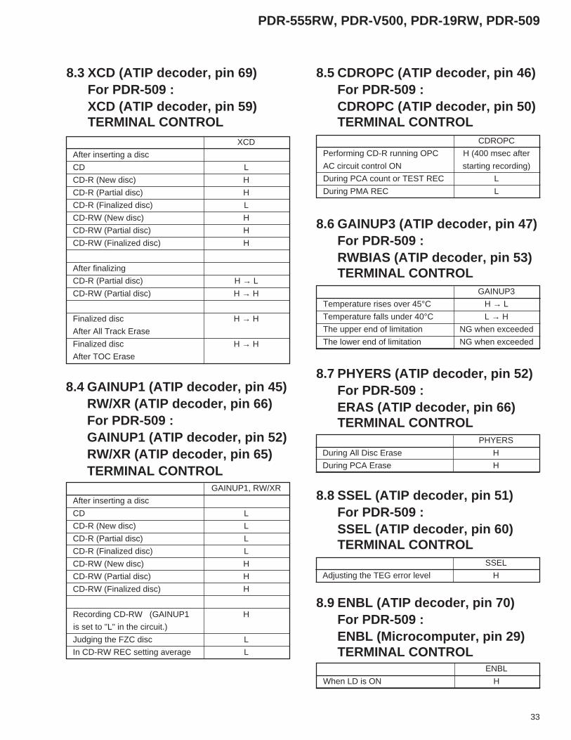
XCD
After inserting a disc
CD L
CD-R (New disc) H
CD-R (Partial disc) H
CD-R (Finalized disc) L
CD-RW (New disc) H
CD-RW (Partial disc) H
CD-RW (Finalized disc) H
After finalizing
CD-R (Partial disc) H → L
CD-RW (Partial disc) H → H
Finalized disc H → H
After All Track Erase
Finalized disc H → H
After TOC Erase
GAINUP1, RW/XR
After inserting a disc
CD L
CD-R (New disc) L
CD-R (Partial disc) L
CD-R (Finalized disc) L
CD-RW (New disc) H
CD-RW (Partial disc) H
CD-RW (Finalized disc) H
Recording CD-RW (GAINUP1 H
is set to "L" in the circuit.)
Judging the FZC disc L
In CD-RW REC setting average L
CDROPC
Performing CD-R running OPC H (400 msec after
AC circuit control ON starting recording)
During PCA count or TEST REC L
During PMA REC L
GAINUP3
Temperature rises over 45°C H → L
Temperature falls under 40°C L → H
The upper end of limitation NG when exceeded
The lower end of limitation NG when exceeded
PHYERS
During All Disc Erase H
During PCA Erase H
SSEL
Adjusting the TEG error level H
ENBL
When LD is ON H
8.3 XCD (ATIP decoder, pin 69)For PDR-509 :XCD (ATIP decoder, pin 59)TERMINAL CONTROL
8.4 GAINUP1 (ATIP decoder, pin 45)RW/XR (ATIP decoder, pin 66)For PDR-509 :GAINUP1 (ATIP decoder, pin 52)RW/XR (ATIP decoder, pin 65)TERMINAL CONTROL
8.5 CDROPC (ATIP decoder, pin 46)For PDR-509 :CDROPC (ATIP decoder, pin 50)TERMINAL CONTROL
8.6 GAINUP3 (ATIP decoder, pin 47)For PDR-509 :RWBIAS (ATIP decoder, pin 53)TERMINAL CONTROL
8.7 PHYERS (ATIP decoder, pin 52)For PDR-509 :ERAS (ATIP decoder, pin 66)TERMINAL CONTROL
8.8 SSEL (ATIP decoder, pin 51)For PDR-509 :SSEL (ATIP decoder, pin 60)TERMINAL CONTROL
8.9 ENBL (ATIP decoder, pin 70)For PDR-509 :ENBL (Microcomputer, pin 29)TERMINAL CONTROL

34
PDR-555RW, PDR-V500, PDR-19RW, PDR-509
9.1 ABOUT POWER ON/OFF9.1.1 Power-up (When the power outlet is
active)
Power (IN)
XPFAIL (IN)
XRST (IN)
Falling of XPFAIL during this period cannot be detected. See (3)-1.
9.1.1.1 Without Backup Power Supply. (When thecontent of RAM of the microcomputer iscleared. )
(1) The power turns on.(2) XPFAIL becomes "H".(3) The reset of the microcomputer then becomes "H" and the
microcomputer starts operating. Immediately after themicrocomputer starts operating, it confirm that XPFAIL = "H."
(3)-1 If XPFAI L= "L," the microcomputer immediately returns toSTOP mode (power-save mode). In this case, backup processis not performed.
9.1.1.2 With Backup Power Supply(1) The power turns on.(2) XPFAIL becomes "H," and the reset of the microcomputer
becomes "L" at the same time.(3) The reset of the microcomputer then becomes "H," and the
microcomputer exits STOP mode and starts operating.Immediately after the microcomputer starts operating, it confirmthat XPFAIL = "H."
(3)-1 If XPFAI L= "L," the microcomputer immediately returnsto STOP mode (power-save mode) again. In this case, backupprocess is not performed.
Power (IN)
XPFAIL (IN)
XRST (IN)
Falling of XPFAIL during this period cannot be detected. See (3)-1.
9.1.2 Power Down (When the power outletis not active or power failure occurs)
(1) The power starts turning off, and XPFAIL becomes "L" whenthe power voltage decreases to some extent.
(2) Interrupted at XPFAI L= "L," and the current operating mode,disc data, etc. are backed up.
(3) As the reset may become "L" about 3 ms after XPFAIL becomeL," the microcomputer must enter STOP mode (power-savemode) before that. (This is because resumption is made withoutdata backup if the microcomputer is reset before it enters STOPmode.)In STOP mode, the reset is pulled up by the backup powersupply.
Power (IN)
XPFAIL (IN)
XSVRST
Microcomputeroperation
About 850µs
It must be lower than 30 ms
XRST (IN)
9.2 ABOUT SERVO CONTROL9.2.1 Seek Track 0The sled is carried to the TOC area (home position).
SLED drive
TOCP input terminal
When TOCP is "H," the sled starts moving toward the inner periphery.
When TOCP becomes "L," the sled moves toward the outer periphery.
When TOCP becomes "H," the sled slowly moves toward the inner periphery.
When TOCP becomes "L" (detected by an interruption), the sled stops, and the operation finishes.
Max. 3.4 sec
Max. 300 ms
Max. 500 ms
1
1
2
2
3
3
4
4
9.2.2 Focus ON9.2.2.1 Without a Disc
Focus drive
200msec 250msec 700msec
1 2
Temporally judging FZC
Executing focus IN
12
9. OPERATION DESCRIPTIONS

35
PDR-555RW, PDR-V500, PDR-19RW, PDR-509
9.2.2.2 With a Disc
Focus drive
FOK
Focus down (preparing for auto focus)
Starting auto focus
Focus IN
1
1
2
2
3
3
9.2.3 One-Track Jump (Direct Sequence)Used for CD-R/RW only.
200µsec
320µsec
1.5msec
Tracking drive
TZC (SENS)
Starts KICK. TZC blind time: 200 µs
Detects TZC rising in FWD (or falling in REV).Starts BREAK. BREAK time: 320 µs.
Detects TZC falling in FWD (or rising in REV).
Finishes GAIN-UP after 1.5 ms.
1
1
2
2
3
3
4
4
9.2.4 One-Track Jump (Auto Sequence)Used for CD/Finalized CD-R only.
405µsec
1.5msec
Tracking drive
XBUSY (SENS)
Starts the auto sequence (starts a jump).
Detects XBUSY (SENS) rising. (The auto sequence ends.)
Finishes GAIN-UP after 1.5 ms.
12
3
1 2 3
202µsec
9.2.5 Ten-Track JumpUsed for CD/CD-R/CD-RW.
Tracking drive
COUT
XBUSY (SENS)
Starts the auto sequence (starts a jump).
Detects XBUSY (SENS) rising. (The auto sequence ends.)
Finishes GAIN-UP after 13 ms (1 loop).
12
3
13msec
1 2 3
202µsec
∗ : The auto sequence ends when the cycle of COUT exceeds Overflow C (405 µs).
9.2.6 2N-Track JumpUsed for CD/Finalized CD-R only.
202µsec 26msec
1 2 3
Tracking drive
COUT
XBUSY (SENS)
Starts the auto sequence (starts a jump).
Detects XBUSY (SENS) rising. (The auto sequence ends.)
Finishes GAIN-UP after 26 ms (2 loops).
12
3
∗ : The auto sequence ends after KICK (D) when the cycle of COUT exceeds Overflow C (405 µs).
36
PDR-555RW, PDR-V500, PDR-19RW, PDR-509
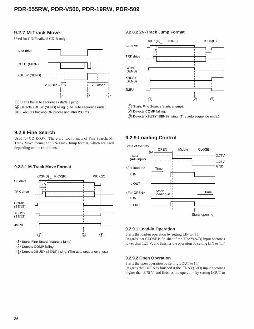
9.2.7 M-Track MoveUsed for CD/Finalized CD-R only.
Sled drive
COUT (MIRR)
XBUSY (SENS)
202µsec 200msec
1 2 3
Starts the auto sequence (starts a jump).
Detects XBUSY (SENS) rising. (The auto sequence ends.)
Executes tracking ON processing after 200 ms
12
3
9.2.8 Fine SearchUsed for CD-R/RW. There are two formats of Fine Search: M-Track Move format and 2N-Track Jump format, which are useddepending on the conditions.
9.2.8.1 M-Track Move Format
1 2 3
SL drive
TRK drive
JMPA
KICK(D) KICK(F) KICK(D)
XBUSY(SENS)
COMP(SENS)
Starts Fine Search (starts a jump).
Detects COMP falling.
Detects XBUSY (SENS) rising. (The auto sequence ends.)
12
3
9.2.8.2 2N-Track Jump Format
1 2 3
SL drive
TRK drive
JMPA
KICK(D) KICK(F) KICK(D)
XBUSY(SENS)
COMP(SENS)
Starts Fine Search (starts a jump).
Detects COMP falling.
Detects XBUSY (SENS) rising. (The auto sequence ends.)
12
3
9.2.9 Loading Control
State of the tray
TRAY(A/D input)
<For load-in>
Startsloading-in
Starts opening
OPEN Middle CLOSE
<For OPEN>
L IN
3.75V
1.25V
5V
GNDTime
Time
L IN
L OUT
L OUT
9.2.9.1 Load-in OperationStarts the load-in operation by setting LIN to "H."Regards that CLOSE is finished if the TRAY(A/D) input becomeslower than 1.25 V, and finishes the operation by setting LIN to "L."
9.2.9.2 Open OperationStarts the open operation by setting LOUT to H."Regards that OPEN is finished if the TRAY(A/D) input becomeshigher than 3.75 V, and finishes the operation by setting LOUT toL."
37
PDR-555RW, PDR-V500, PDR-19RW, PDR-509
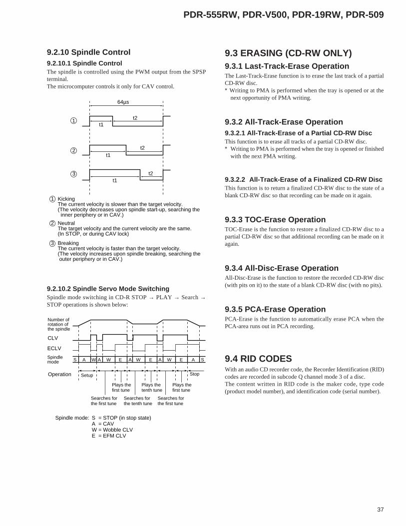
9.2.10 Spindle Control9.2.10.1 Spindle ControlThe spindle is controlled using the PWM output from the SPSPterminal.The microcomputer controls it only for CAV control.
64µs
t2t1
t1t2
t1t2
1
2
3
KickingThe current velocity is slower than the target velocity. (The velocity decreases upon spindle start-up, searching the inner periphery or in CAV.)
NeutralThe target velocity and the current velocity are the same.(In STOP, or during CAV lock)
BreakingThe current velocity is faster than the target velocity. (The velocity increases upon spindle breaking, searching the outer periphery or in CAV.)
1
2
3
9.2.10.2 Spindle Servo Mode SwitchingSpindle mode switching in CD-R STOP → PLAY → Search →STOP operations is shown below:
Number of rotation of the spindle
CLV
S SA W W W WE E EA A A A
ECLV
Spindle mode
Setup Stop
Searches for the first tune
Searches for the first tune
Searches for the tenth tune
Plays the first tune
Plays the first tune
Plays the tenth tune
Operation
Spindle mode: S = STOP (in stop state)A = CAVW = Wobble CLVE = EFM CLV
9.3 ERASING (CD-RW ONLY)9.3.1 Last-Track-Erase OperationThe Last-Track-Erase function is to erase the last track of a partialCD-RW disc.∗ Writing to PMA is performed when the tray is opened or at the
next opportunity of PMA writing.
9.3.2 All-Track-Erase Operation9.3.2.1 All-Track-Erase of a Partial CD-RW DiscThis function is to erase all tracks of a partial CD-RW disc.∗ Writing to PMA is performed when the tray is opened or finished
with the next PMA writing.
9.3.2.2 All-Track-Erase of a Finalized CD-RW DiscThis function is to return a finalized CD-RW disc to the state of ablank CD-RW disc so that recording can be made on it again.
9.3.3 TOC-Erase OperationTOC-Erase is the function to restore a finalized CD-RW disc to apartial CD-RW disc so that additional recording can be made on itagain.
9.3.4 All-Disc-Erase OperationAll-Disc-Erase is the function to restore the recorded CD-RW disc(with pits on it) to the state of a blank CD-RW disc (with no pits).
9.3.5 PCA-Erase OperationPCA-Erase is the function to automatically erase PCA when thePCA-area runs out in PCA recording.
9.4 RID CODESWith an audio CD recorder code, the Recorder Identification (RID)codes are recorded in subcode Q channel mode 3 of a disc.The content written in RID code is the maker code, type code(product model number), and identification code (serial number).
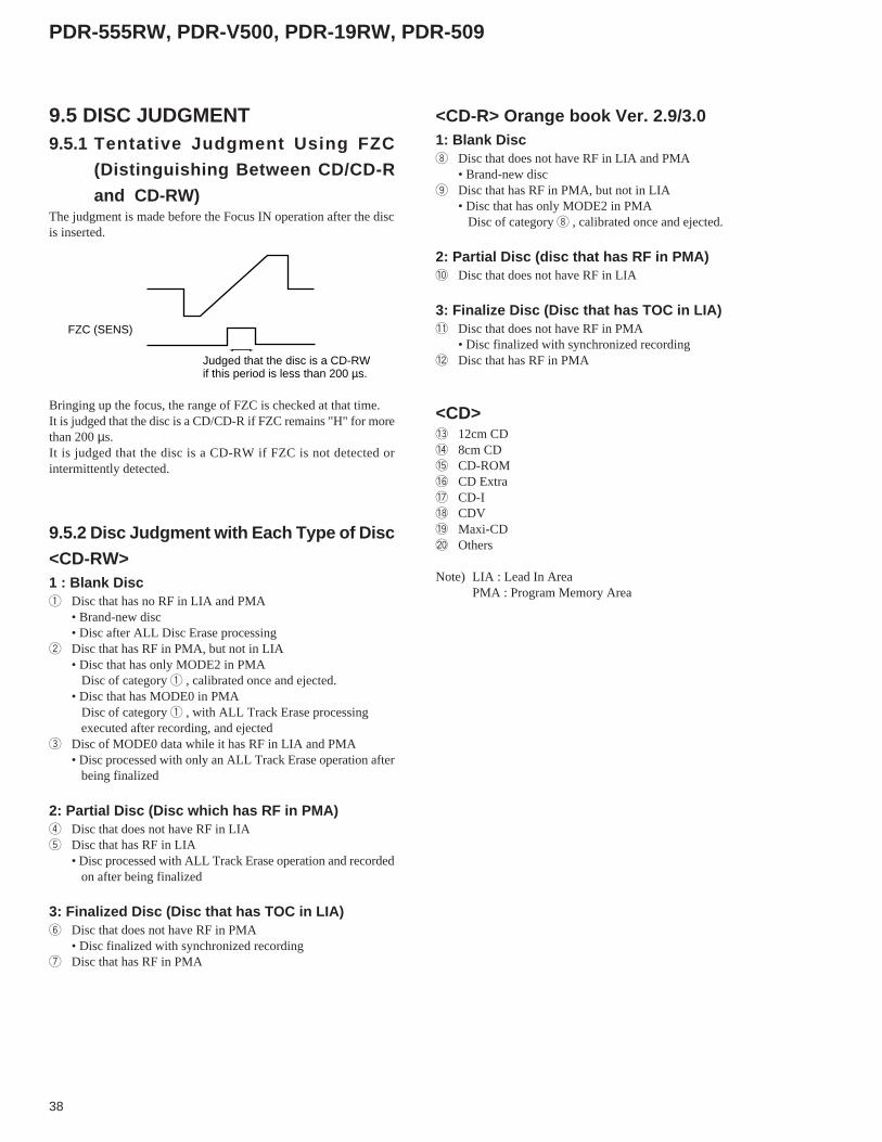
38
PDR-555RW, PDR-V500, PDR-19RW, PDR-509
9.5 DISC JUDGMENT9.5.1 Tentative Judgment Using FZC
(Distinguishing Between CD/CD-R
and CD-RW)The judgment is made before the Focus IN operation after the discis inserted.
FZC (SENS)
Judged that the disc is a CD-RW if this period is less than 200 µs.
Bringing up the focus, the range of FZC is checked at that time.It is judged that the disc is a CD/CD-R if FZC remains "H" for morethan 200 µs.It is judged that the disc is a CD-RW if FZC is not detected orintermittently detected.
9.5.2 Disc Judgment with Each Type of Disc
<CD-RW>1 : Blank Disc1 Disc that has no RF in LIA and PMA
• Brand-new disc• Disc after ALL Disc Erase processing
2 Disc that has RF in PMA, but not in LIA• Disc that has only MODE2 in PMA Disc of category 1 , calibrated once and ejected.• Disc that has MODE0 in PMA Disc of category 1 , with ALL Track Erase processing executed after recording, and ejected
3 Disc of MODE0 data while it has RF in LIA and PMA• Disc processed with only an ALL Track Erase operation after being finalized
2: Partial Disc (Disc which has RF in PMA)4 Disc that does not have RF in LIA5 Disc that has RF in LIA
• Disc processed with ALL Track Erase operation and recorded on after being finalized
3: Finalized Disc (Disc that has TOC in LIA)6 Disc that does not have RF in PMA
• Disc finalized with synchronized recording7 Disc that has RF in PMA
<CD-R> Orange book Ver. 2.9/3.01: Blank Disc8 Disc that does not have RF in LIA and PMA
• Brand-new disc9 Disc that has RF in PMA, but not in LIA
• Disc that has only MODE2 in PMA Disc of category 8 , calibrated once and ejected.
2: Partial Disc (disc that has RF in PMA)0 Disc that does not have RF in LIA
3: Finalize Disc (Disc that has TOC in LIA)- Disc that does not have RF in PMA
• Disc finalized with synchronized recording= Disc that has RF in PMA
<CD>~ 12cm CD! 8cm CD@ CD-ROM# CD Extra$ CD-I% CDV^ Maxi-CD& Others
Note) LIA : Lead In AreaPMA : Program Memory Area
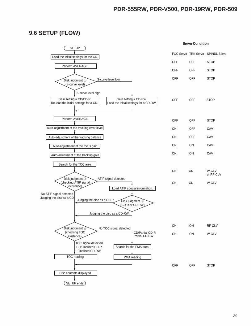
39
PDR-555RW, PDR-V500, PDR-19RW, PDR-509
9.6 SETUP (FLOW)
SETUP
SETUP ends
Load the initial settings for the CD.
Perform AVERAGE.
Gain setting = CD/CD-RRe-load the initial settings for a CD.
S-curve level high
S-curve level lowDisk judgment 1(S-curve level)
Perform AVERAGE.
Auto-adjustment of the tracking error level
Gain setting = CD-RW Load the initial settings for a CD-RW.
Auto-adjustment of the tracking balance
Auto-adjustment of the focus gain
Disk judgment 2(checking ATIP signal
existence)
Disk judgment 3(CD-R or CD-RW)
Disk judgment 4(checking TOC
existence)
Auto-adjustment of the tracking gain
Search for the TOC area
No ATIP signal detectedJudging the disc as a CD
Judging the disc as a CD-R.
Judging the disc as a CD-RW.
TOC signal detectedCD/Finalized CD-RFinalized CD-RW
CD/Partial CD-RPartial CD-RW
No TOC signal detected
ATIP signal detected
TOC reading
Disc contents displayed
Load ATIP special information.
PMA reading
Search for the PMA area.
Servo Condition
FOC Servo TRK Servo SPINDL Servo
OFF OFF STOP
OFF OFF STOP
OFF OFF STOP
OFF OFF STOP
OFF OFF STOP
ON OFF CAV
ON OFF CAV
ON ON CAV
ON ON CAV
ON ON RF-CLV
ON ON W-CLV
OFF OFF STOP
ON ON W-CLVor RF-CLV
ON ON W-CLV

40
PDR-555RW, PDR-V500, PDR-19RW, PDR-509
9.6.1 Verification of Disc Judgments1. Tentative judgment by FZC (distinguishing
between CD/CD-R and CD-RW)
2. Tentative judgment by checking the RF existence
at TOCP
< If RF exists >The disc may be a finalized CD or CD-R/RW or an erased CD-RW.If the disc was judged to be a CD-RW in FZC tentative judgment, itremains judged as a CD-RW (the disc status is CD-R).If the disc was judged to be a CD/CD-R in FZC tentative judgment,it is tentatively judged to be a CD.
< If RF does not exist >The disc has strong likelihood of CD-R or CD-RW.If the disc was judged as CD-RW in FZC tentative judgment, it isjudged as CD-RW. If the disc was judged to be a CD/CD-R in FZCtentative judgment, it is judged to be a CD.
3. Tentative judgment (3) by checking the RF
existence in LIA (99:00:00)When the setup is finished with the results of tentative judgments 1and 2, the RF existence is verified while searching for LIA (99:00:00)and executing AGC (gain adjustment).
< If RF exists >The results of the tentative judgment indicates:The CD may be a CD.The CD-R may be a finalized CD-R.The CD-RW may be finalized CD-RW or erased CD-RW.
< If RF does not exist >The result of the tentative judgment indicates:CD → no possibilityThe CD-R may be a partial CD-R or blank CD-R.The CD-RW may be a partial CD-RW or blank CD-RW.
4. Disc determination by reading the ATIP special
informationIf the result of tentative judgment indicates the disc is a CD-RW,and ATIP also indicates it is a CD-RW, the disc is determined to bea CD-RW.In the tentative judgment by checking the RF existence in LIA(99:00:00): If RF exists → Loads TOC, as there is a possibility that the
disc is a finalized CD-RW. If no RF exists → Makes a decision depending on the result of
PMA loading, since the disc may be a partialCD-RW or blank CD-RW.
If both the result the tentative judgment and ATIP do not indicate itis a CD-RW, the disc is determined to be a CD-R.
In the tentative judgment by checking the RF existence in LIA(99:00:00): If RF exists → Loads TOC, as there is a possibility that the
disc is a finalized CD-R. If no RF exists → Makes a decision depending on the result of
PMA loading, since the disc may be a partialCD-RW or blank CD-R.
When the ATIP special information cannot be read, the disc isdetermined to be a CD.
If the results of FZC tentative judgment and ATIP indicate it to beof a different type, a retry is made by reversing the result of FZCtentative judgment.
5. Disc-type determination by reading TOCIf MODE0 data are detected while reading TOC with CD-RW, thedisc status is changed to Partial CD-RW and the operation shifts toPMA reading.
9.6.2 Auto-Adjustments9.6.2.1 Calibration of Tracking Offset Adjust Ability
and Verification of the Temperature SensorThese are carried out upon POWER ON and SETUP.
(1) Calibration of the tracking offset adjustment
ability• When ADR_RFB and ADR_RFT are 1.5 to 3 V, the values are
stored in VRB_REF and VRT_REF respectively.• When ADR_RFB are ADR_RFT are not 1.5 to 3 V, the mode-
control computer is notified through the TOKNG_F setting thatthe initial values for the RF envelope signal cannot be obtained.In this case, the mode-control computer generates a STOPcommand if the setup step is before PCA. The values are storedin VRB_REF and VRT_REF, respectively.
(2) Verification of the temperature sensorUpon POWER ON, the temperature sensor is checked whether thesensor shows a value within -15°C to 70°C. If it is out of the range,the sensor is judged defective, and subsequent operations are madein the temperature sensor defect status.
9.6.3 Tracking Error Level Adjustment and
Disc DeterminationThe tracking error level adjustment and disc determination aresimultaneously executed when a disc is inserted. The tentativejudgment made in this stage checks the RF existence in the lead-inarea. If RF exists, the disc is tentatively judged to be a CD. If no RFexists, the disc is tentatively judged to be a CD-R.However, if the result of the tentative judgment using FZC indicatesit is a CD-RW, the disc is determined as CD-R regardless of the RFexistence.

41
PDR-555RW, PDR-V500, PDR-19RW, PDR-509
9.6.4 Recording Power Sweep Mode for
Recording Power Calibration
9.6.4.1 Sweep recording on CD-R• Sweep recording of ±2 steps of the reference power is made three
times.
15 frames
Recording Power Sweep
Reference power
+1
+2
–1–2
1 frame
9.6.4.2 Sweep recording on a CD-RW• Sweep recording of -1 mW to +3 mW of the reference power is
made three times.
+1mW+2mW
+3mW
–1mW
15 frames
Recording Power Sweep
Reference power
1 frame
9.6.5 Playback RF Estimating Mode for
Recording Power CalibrationThe PCA TEST area recorded in Recording Power Sweep mode isplayed back to check the RF waveform and find the optimumrecording power.
10. ABOUT TEST MODE
OPERATIONSTest mode is provided to permit you to easily achieve adjustmentsand confirmation required for servicing.When you set the unit to Test mode, the front-panel keys havedifferent functions from these in Normal mode. By operating thesekeys in the specified sequence, you can perform the requiredadjustments and confirmations.
[Setting the unit to Test mode]You can set the unit to Test mode with the following procedure:
1. Turn off the power.2. Short-circuit the pattern for Test mode.3. Turn on the power.
(When the unit enters Test mode, RAM information of themechanism control is cleared.)
If Test mode is set correctly, displays different from those in ordinarypower-up state are obtained. (All the FL indicators light, and RECLED lights in amber. (For PDR-509, REC LED lights in red. ) )If the displays are the same as those in the normal mode, Test modemay not have been set correctly. Repeat steps 1 to 3 above.
Caution: Before setting the unit to Test mode, be sure to set theINPUT selector to ANALOG.If the selector is not set to ANALOG, malfunctions mayoccur in Adjustment mode.
[Releasing Test mode]You can release Test mode with the following procedure:1. Press the STOP key to stop all operations.2. Turn off the power.
Relationship between Test mode and Normal mode
Normal mode
Test mode Mechanism servo control for adjustments
Playback
Recording
Finalizing
• • • • •

42
PDR-555RW, PDR-V500, PDR-19RW, PDR-509
[Key Functions in Test Mode]
Operations common to Adjustment modes and other modes
emaNyeK edoMtseTninoitarepO snoitpircseD
EZILANIF esolcovressucoF
rotautcasucofehtpugnivomylwols,rewopkcabyalpehthtiwedoidresalehtnosnruTsisneltcejboehtfosucofehterehwovressucofehtsesolcdna,nwodtignivomretfa
yamuoy,sregnifybnoitidnocsihtnietatspotsnicsidehtetatoryltneguoyfI.deniatbo.yltcerrocgnitareposiovressucofehtnehwdetarenegdnuosehtraeh
rotautcasucofehT.sthgiledoidresaleht,csidagnidaoltuohtiwyekehtsserpuoyfItineht,tnemevomnwodtsrifehtretfasemiteerhtstnemevomnwoddnapustaeper
.noitisoplanigiroehtotsnruter
YALP NOovreSeldnipSdesolcotovreseldnipsehtstesdna,noitatoresiwkcolcrofrotomeldnipsehtpustratStampr005tuoba(eulavdeificepsehtsehcaercsidehtfodeepsnoitatorehtnehwpool
.)yrehpireprennieht
ESUAP nepo/esolcovreSgnikcarT
yltcerrocsiovreseldnipsehtdnaovressucofehttahtnoitidnocaniyeksihtsserpuoyfIdnarebmunkcarttnerruceht,pooldesolcaottessiovresgnikcarteht,pooldesolcani
.tuptuosilangiskcabyalpehtdna,lenaptnorfehtnodeyalpsideraemitdespaleehttonsioiduaehtfiro,ylralugerputnuoctonseodtifi,deyalpsidtonsiemitdespaleehtfI
,csidehtfoaeradnuos-onlarehpirepretuoehtnitcefedaebyamereht,yltcerrocdetnuoc.smelborprehtoroecnanetniamroop
gnikcartehtsesolcrosnepoyekehtfosserphcaE.hctiwselggotasasnoitcnufyekehT.sruccoegnahcon,csidagnidaoltuohtiwyeksihtsserpuoyfI.nrutniovres
otnommocyeKHCRAESLAUNAM
dnaVERLAUNAM/KART
VER
esreveRegairraC)yrehpireprenniehtdrawot(
.csidafoyrehpireprenniehtdrawotpukcipehtstropsnarTyllacitamotuapooleht,pooldesolcanisiovresgnikcartehtnehwyekehtsserpuoyfIehtecnis,yeksihtgnitareponehwnekatebtsumeractneiciffus,edomtseTnI.snepo
.dnelacisyhpehtsehcaerpukcipehtnehwnevepotsyllacitamotuatonseodrotom
otnommocyeKHCRAESLAUNAM
roDWFLAUNAM/KCART
DWF
drawroFegairraC)yrehpirepretuoehtdrawot(
.csidafoyrehpirepretuoehtotpukcipehtstropsnarTyllacitamotuapooleht,pooldesolcanisiovresgnikcartehtnehwyekehtsserpuoyfIehtecnis,yeksihtgnitareponehwnekatebtsumeractneiciffus,edomtseTnI.snepo
.dnelacisyhpehtsehcaerpukcipehtnehwnevepotsyllacitamotuatonseodrotom
POTS potS.setatslaitiniriehtotmehtsnruterdnasovresllaspotS
.desserpsawyekPOTSehtnehwnisawtinoitisopehtnisyatspukcipeht,revewoH
ESOLC/NEPO esolc/nepoyartcsiD
.yartcsidehtsesolcdnasnepO.nrutniyartcsidehtesolcronepohsuphcaE.hctiwselggotasasnoitcnufyeksihT
fonoitatorehtretfasnepoyartcsideht,gnitatorsicsidehtelihwyekehtsserpuoynehW.spotscsideht
CER↓
ETUMCER
)DC(rewopkcabyalPrewopgnidrocermumixaM
)WR-,R-DC(NOedoidresaL
)edomtnemtsujdAtpecxe(
ehtsthgildna,noitidnocrewopgnidrocermumixamehtsedivorpyekCERehtgnisserPgnittesDCehthtiwyekETUM/CERehtfognisserptneuqesbuS.neergniDELCERWR-DCroR-DChtiW.rewopkcabyalpehtstuptuodna,rebmaniDELCERehtsthgil
lamronybtuptuosirewopgnidrocermumixamehtdnadernisthgilDELCEReht,gnittesybgnittesWR-DCroR-DCehthtiwrewopgnidrocermumixamehtlecnacuoyfI.MFE
.DCaroftahtotsnruteryllacitamotuagnitteseht,yekPOTSehtgnisserp:noituaC .tnemtsujdaerofebyekehtsserpuoyfidegamadebyamedoidresalehT
,dersthgilDELCEReht,dehsupsiyekETUMCERehtnehw,905-RDProF.thgiltonseodDELCEReht,dehsupsiyekCERehtfineve
43
PDR-555RW, PDR-V500, PDR-19RW, PDR-509
Adjustment modes (with the INPUT selector set to OPTICAL (OPT))
Modes other than adjustment mode (with the INPUT selector set to ANALOG)
emaNyeK edomtseTninoitarepO snoitpircseDFFOYALPSID .DELFFO_PSIDehtffo/nonrutoT
ETIRWLAUNAM .DEL]LAUNAM[ehtffo/nonrutoT
ESARE .csidfoepytehtyficepsoT.csiddeificepsehthtiwecnadroccanisovresehtsehctiwsoT
DCfoecneuqesehtnisehctiwsyllacilcyctupniyekehT → R-DC → .WR-DC.etatsPOTSniylnodelbanesignihctiwS.tilnehterayalpsidLFehtnostnemgescsidehT
ROTCELESTUPNIWS
tnemtsujdaehttcelesoT.sedom
ehtdna,thgilstnemgesCLAeht,GOLANAottestonsirotcelesTUPNIehtnehWonnehwGOLANAotrotcelesehtnruteroteruseB:delbaneerastnemtsujdagniwollof
.edamsitnemtsujda
LAUNAM/OTUAtnemtsujdaehttcelesoTehtllaffonrutoT.sedom
.snoitacidniLF
ebnacsedomtnemtsujdaevobaeht,GOLANAottestonsirotcelesTUPNIehtnehWLFehtllaffosnrutGOLANAottesrotcelesTUPNIehthtiwyekehtgnisserP.detceles
.sdnoces5tuobarofsnoitacidni
CER,905-RDProF
LAIDGOJesiwkcolcretnuoC
tnemtsujdaehtegnahcoTnoitceridsunimehtnieulav
.deyalpsiddnanoitceridsunimehtnidegnahcsieulavtnemtsujdaehT
ETUM/CER,905-RDProF
LAIDGOJesiwkcolC
tnemtsujdaehtegnahcoTnoitceridsulpehtnieulav
.deyalpsiddnanoitceridsulpehtnidegnahcsieulavtnemtsujdaehT
TESPIKS,905-RDProF
LAIDGOJ
detsujdaehtretsigeroT.eulav
stnemges"?"eht,detelpmocyltcerrocsipukcabnehW.deretsigersieulavdetsujdaehT.kradoglliw
RAELCPIKSgnicnalabkcartehttceridoT
ehtezilaitinioT.ssecorp.eulavtnemtsujda
gnikcartehtdna,tupniyeknoputnemomarofthgil)yalpsidgnilpmas(stnemges23ehTdnaNOSUCOFretfaedamebtsumnoitarepoyeksihT.detucexesissecorpecnalab
sieulavtnemtsujdaeht,sdnoces4rofdesserpdlehsiyekehtnehW.NOELDNIPS.kradoglliwstnemges"?"eht,detelpmocyltcerrocsipukcabehtnehW.dezilaitini
etomer(CNYS)MODNAR:lortnoc
gnigarevaehttceridoT.ssecorp
.detucexesissecorpgnigarevaehtdna,tupniyeknoputhgilstnemges84ehT.csidfoepytehtgniyficepsretfaetatsPOTSniedamebtsumnoitarepoyeksihT
emaNyeK edomtseTninoitarepO snoitpircseDFFOYALPSID .DELFFO_PSIDehtffo/nonrutoT
ETIRWLAUNAM .DEL]LAUNAM[ehtffo/nonrutoT
ESARE csidfoepytehtyficepsoTyllacilcyctupniyekehT.csiddeificepsehthtiwecnadroccanisovresehtsehctiwsoT
DCfoecneuqesehtnisehctiws → R-DC → .WR-DC.etatsPOTSniylnodelbanesignihctiwS.tilnehterayalpsidLFehtnostnemgescsidehT
LAUNAM/OTUAtnemtsujdaehttcelesoT
LFehtllaffonrutoT.sedom.snoitacidni
ebnacsedomtnemtsujdaevobaeht,GOLANAottestonsirotcelesTUPNIehtnehWLFehtllaffosnrutGOLANAottesrotcelesTUPNIehthtiwyekehtgnisserP.detceles
.sdnoces5tuobarofsnoitacidni
CER .rewopgnidrocermumixamehtgnittuptuorofdesU
ETUM/CER .rewopgnidrocermumixamehtgnittuptuorofdesU
FFO/NOPIKS,905-RDProF
EMITemitdeyalpsidehthctiwsoT
.stnemgesPIKSehtffo/nonrutoTehtnehW.deyalpsidsicsidafoemitetulosbaeht,noerastnemgesPIKSehtnehW.deyalpsidsicsidafokcarthcaefoemitatad-Qdespaleeht,ffoerastnemgesPIKS
etomer(CNYS)MODNAR:lortnoc
gnigarevaehttceridoTssecorp
.detucexesissecorpgnigarevaehtdna,tupniyeknoputhgilstnemges84ehT.csidfoepytehtgniyficepsretfaetatsPOTSniedamebtsumnoitarepoyeksihT
Caution: Each servo operates independently in Test mode. So, for disc playback, you have to operate the keys by the correct procedure andsequentially close the servos.

44
PDR-555RW, PDR-V500, PDR-19RW, PDR-509
[Playing a disc in Test mode]Operate the keys in the following sequence to play a disc.
FINALIZE Lights the laser diode and closes the focusservo.(The PGM key is also valid.)
↓
PLAY Starts up the spindle motor and closes thespindle servo.
↓
PAUSE Closes the tracking servo.
Operate the keys in a 2- to 3-second intervals
[Switching the time display in Test mode]When the INPUT selector is set to ANALOG, you can change thetime display with tracking on by pressing the SKIP ON/OFF key.SKIP OFF (SKIP segments lit) : Absolute time (ATIME)SKIP ON (SKIP segments unlit) : Sub Q TIMEFor PDR-509, this key becomes TIME Key.
[Operation for line adjustment in Test
mode]Operating procedure:1 Set to Test mode after setting the INPUT selector to ANALOG.2 Make preparations for measurements.3 Set the INPUT selector to OPTICAL (OPT) or COAXIL
(COAX). (The ALC segments light.)4 Select the adjustment items with the AUTO/MANUAL key.
You can select the adjustment items for steps 3 and 4 in thecombinations listed below.After operation of steps 3 and 4, the adjustment item number isdisplayed at TNO of the FL display, and the current set value of thatitem is displayed at MIN and SEC.
5 Press the REC key to change the value to the minus direction orthe REC MUTE key to change it in the plus direction.(For PDR-509, the value changes into the direction of the plus ifJOGDIAL turns clockwise. The value changes into the directionof the minus if JOGDIAL turns counterclockwise.)You may see the Q data or ATIP data of the disc by switchingthe INPUT selector to ANALOG in this state. If you set theINPUT selector back to OPTICAL (OPT) again, the formeradjustment item is resumed.
6 When the desired value is set, register it by pressing the SETkey.The registered value lights and the "?" segments go dark whenthe backup of the value in EEPROM is completed.
7 If you wish to initialize adjustment values 1 to 4 to the defaultvalues of the microcomputer, press and hold the SKIP CLEARkey for about 4 seconds with the INPUT selector set to OPTICAL(OPT) or COAXIL (COAX). Adjustment values 1 to 4 areinitialized and registered in EEPROM.
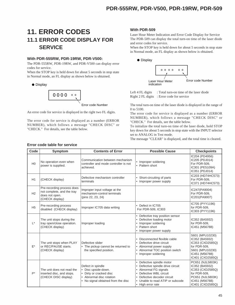
45
PDR-555RW, PDR-V500, PDR-19RW, PDR-509
11. ERROR CODES11.1 ERROR CODE DISPLAY FOR SERVICE
With PDR-555RW, PDR-19RW, PDR-V500:The PDR-555RW, PDR-19RW, and PDR-V500 can display errorcodes for service.When the STOP key is held down for about 5 seconds in stop statein Normal mode, an FL display as shown below is obtained.
Error code Number
Display
An error code for service is displayed in the right two FL digits.
The error code for service is displayed as a number (ERRORNUMBER), which follows a message "CHECK DISC" or"CHECK." For details, see the table below.
With PDR-509Laser Hour Meter Indication and Error Code Display for ServiceThe PDR-509 can display the total turn-on time of the laser diodeand error codes for service.When the STOP key is held down for about 5 seconds in stop statein Normal mode, an FL display as shown below is obtained.
Left 4 FL digits : Total turn-on time of the laser diodeRight 2 FL digits : Error code for service
The total turn-on time of the laser diode is displayed in the range of0 to 5100.The error code for service is displayed as a number (ERRORNUMBER), which follows a message "CHECK DISC" or"CHECK." For details, see the table below.To initialize the total turn-on time of the laser diode, hold STOPkey down for about 5 seconds in stop state with the INPUT selectorset to ANALOG in Test mode.The message "CLEAR" is displayed, and the total time is cleared.
Error code NumberLaser Hour Meterindication
Display
Error code table for service
edoC motpmyS rorrEfostnetnoC esuaCelbissoP stniopkcehC
0HnehwnevenoitarepooN
.deilppussirewop
msinahcemneewtebnoitacinummoCtonsirellortnocedomdnarellortnoc
.deveihca
gniredlosreporpmI•trohsnrettaP•
)6594DP(402CI)410JDP(502CI
,905-RDProF)A9015EP(103CI
)410JDP(153CI
1H )yalpsidKCEHC(rellortnocmsinahcemevitcefeD
slanimretstrapfognitiucric-trohS•ylppusrewopreporpmI•
)375CH47DH(302CI,905-RDProF
)375CH47DH(173CI
2H
seodssecorpgnidrocer-erPyartehtdna,etelpmocton
.nepotonseod)yalpsidKCEHC(
ehttaegatlovtupnireporpmIslanimretlortnoc-msinahcem
)42,32,22snip(
)4009AP(742CI,905-RDProF
)7009AP(102CI
5Hssecorpgnidrocer-erP
)yalpsidKCEHC(delbasidgnitirwatad507CIreporpmI
507CInitcefeD•303CI,905-RDProF
)6911YYP(507CI,905-RDProf
)6911YYP(303CI
L∗ehtgnirudspotstinuehT
.noitarepoesolc/nepoyart)yalpsidKCEHC(
gnidaolreporpmI
rosnesnoitisopyartevitcefeD•rotomgnidaolevitcefeD•
gniredlosreporpmI•trohsnrettaP•
ylppusrewopreporpmI•
)2395AB(253CI,905-RDProf
)88765M(154CI
E∗YALPnehwspotstinuehT
.stratsESUAP/CERro)yalpsidKCEHC(
redilsevitcefeDotdenruterebtonnacpukcipehT•
.noitisopdeificepseht
elbacelbixelfdetcennocsiD•tiucricevirdevitcefeD•
ylppusrewoplamronbA•hctiwsnoitisopCOTlamronbA•
gniredlosreporpmI•
)03201UPM(106S)2395AB(253CI
)Q5852DXC(353CI,905-RDProf
)03201UPM(106S)88765M(154CI
)Q5852DXC(104CI
P∗ehtdaertonseodtinuehT
.spotsdna,csiddetresni)yalpsidCSIDKCEHC(
eldnipsnitcefeD.nwod-edispucsiD•
csiddekcarcroytriD•noitatorcsidlamronbA•
csidehtmorfdeniatbolangisoN•
rotomeldnipsevitcefeD•tiucricevirdeldnipsevitcefeD•
slangisGFlamronbA•tiucricLBWevitcefeD•
tiucricredocedevitcefeD•edocbusroPITAdaerotelbanU•
etarrorrehgiH•
)K3085LJN(156CP)2395AB(253CI
)Q5852DXC(353CI,905-RDProf
)K3085LJN(156CP)88765M(154CI
)Q5852DXC(104CI

46
PDR-555RW, PDR-V500, PDR-19RW, PDR-509
edoC motpmyS rorrEfostnetnoC esuaCelbissoP stniopkcehC
C∗ tierofebspotstinuehT.edomESUAP/CERsretne
resalgnidrocerehtotdetalerstcefeDrewop
csiddekcarcroytriD•rewopgnidrocermumitpoehT•
.deniatboebtonnac.noitcetedFRnielbuorT•
edoidresalevitcefeD•noitcetedFRnielbuorT•
tiucricBFRTFRevitcefeD•.tneiciffustonsirewopgnidroceR•trohsnrettap,gniredlosreporpmI•
ylppusrewophtiwelbuorT•edocbusroPITAdaerotelbanU•
)4009AP(742CI)3658KA(301CI)40S7CT(802CI)41S7CT(902CI
,905-RDProf)7009AP(102CI)3658KA(101CI)40S7CT(363CI)41S7CT(463CI
F∗ gnirudspotstinuehT.gnidrocerrokcabyalp
pukcipevitcefeDrotridfoesuacebsucofotelbanU•
.csiddetresniehtnokcarcresalreporpehttuptuootelbanU•
rewop
edoidresalevitcefeD•stiucricevirdsucofevitcefeD•
pukcipevitcefeD•gniredlosreporpmI•
trohsnrettaP•ylppusrewopfoelbuorT•
)2395AB(253CI)Q5852DXC(353CI
,905-RDProf)88765M(154CI
)Q5852DXC(104CI
A∗anispotstinuehT
,noitarepodetaler-gnidrocer".CSIDKCEHC"gniyalpsid
sucofotelbanU•gnidrocergnirudpotS
ybdetcurtsbognieb,spotstinuehT•.csidehtnokcarcarotrida
erofebsruccoelbuorterawdrahynafIAgniyalpsid ∗ dro ∗ spotstinueht,
esehtnahtrehtoedocagniyalpsidecivreseseht,eroferehT.sedoc
selbuortrofylnodetarenegerasedoc.csidehthtiw
d∗
gnidroceranispotstinuehTgniyalpsid,noitarepodetaler
".CSIDKCEHC"ehtdaertonseodtinuehT
.spotsdna,csiddetresni
.oN edoMmsinahceM .oN edoMmsinahceM .oN edoMmsinahceM
0 YALP 5 PUTES A CER
1 NEPO 6 DAERCOT B CERCOT
2 POTS 7 − C CPO
3 − 8 HCRAES D KCEHCCOT
4 − 9 ESUAP/CER E CERESUAPLAUTCA,AMP
The indication for ∗ shows the mechanism mode listed below:
Initializing the Error Code DisplayTo clear the error codes, hold the "MENU" key down for about 10seconds in Normal mode.
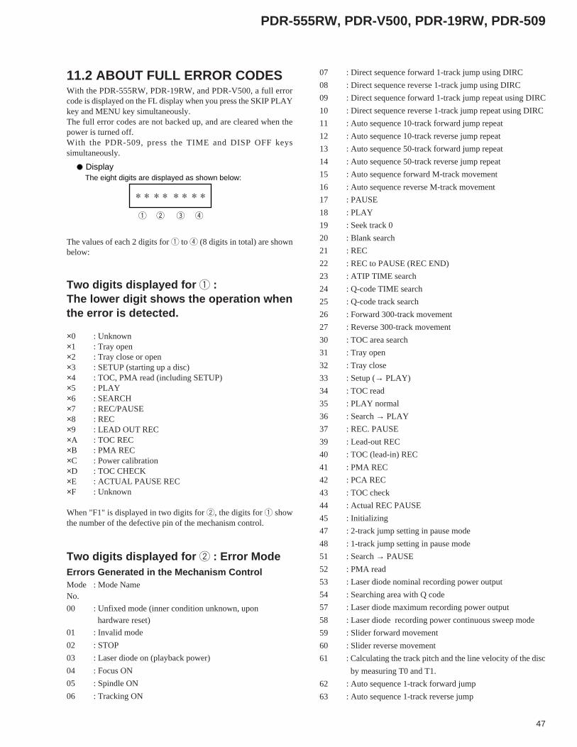
47
PDR-555RW, PDR-V500, PDR-19RW, PDR-509
11.2 ABOUT FULL ERROR CODESWith the PDR-555RW, PDR-19RW, and PDR-V500, a full errorcode is displayed on the FL display when you press the SKIP PLAYkey and MENU key simultaneously.The full error codes are not backed up, and are cleared when thepower is turned off.With the PDR-509, press the TIME and DISP OFF keyssimultaneously.
The eight digits are displayed as shown below:Display
The values of each 2 digits for 1 to 4 (8 digits in total) are shownbelow:
Two digits displayed for 1 :The lower digit shows the operation whenthe error is detected.
×0 : Unknown×1 : Tray open×2 : Tray close or open×3 : SETUP (starting up a disc)×4 : TOC, PMA read (including SETUP)×5 : PLAY×6 : SEARCH×7 : REC/PAUSE×8 : REC×9 : LEAD OUT REC×A : TOC REC×B : PMA REC×C : Power calibration×D : TOC CHECK×E : ACTUAL PAUSE REC×F : Unknown
When "F1" is displayed in two digits for 2, the digits for 1 showthe number of the defective pin of the mechanism control.
07 : Direct sequence forward 1-track jump using DIRC
08 : Direct sequence reverse 1-track jump using DIRC
09 : Direct sequence forward 1-track jump repeat using DIRC
10 : Direct sequence reverse 1-track jump repeat using DIRC
11 : Auto sequence 10-track forward jump repeat
12 : Auto sequence 10-track reverse jump repeat
13 : Auto sequence 50-track forward jump repeat
14 : Auto sequence 50-track reverse jump repeat
15 : Auto sequence forward M-track movement
16 : Auto sequence reverse M-track movement
17 : PAUSE
18 : PLAY
19 : Seek track 0
20 : Blank search
21 : REC
22 : REC to PAUSE (REC END)
23 : ATIP TIME search
24 : Q-code TIME search
25 : Q-code track search
26 : Forward 300-track movement
27 : Reverse 300-track movement
30 : TOC area search
31 : Tray open
32 : Tray close
33 : Setup (→ PLAY)
34 : TOC read
35 : PLAY normal
36 : Search → PLAY
37 : REC. PAUSE
39 : Lead-out REC
40 : TOC (lead-in) REC
41 : PMA REC
42 : PCA REC
43 : TOC check
44 : Actual REC PAUSE
45 : Initializing
47 : 2-track jump setting in pause mode
48 : 1-track jump setting in pause mode
51 : Search → PAUSE
52 : PMA read
53 : Laser diode nominal recording power output
54 : Searching area with Q code
57 : Laser diode maximum recording power output
58 : Laser diode recording power continuous sweep mode
59 : Slider forward movement
60 : Slider reverse movement
61 : Calculating the track pitch and the line velocity of the disc
by measuring T0 and T1.
62 : Auto sequence 1-track forward jump
63 : Auto sequence 1-track reverse jump
Two digits displayed for 2 : Error ModeErrors Generated in the Mechanism ControlMode : Mode NameNo.
00 : Unfixed mode (inner condition unknown, upon hardware reset)
01 : Invalid mode
02 : STOP
03 : Laser diode on (playback power)
04 : Focus ON
05 : Spindle ON
06 : Tracking ON
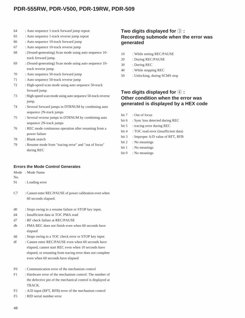
48
PDR-555RW, PDR-V500, PDR-19RW, PDR-509
64 : Auto sequence 1-track forward jump repeat
65 : Auto sequence 1-track reverse jump repeat
66 : Auto sequence 10-track forward jump
67 : Auto sequence 10-track reverse jump
68 : (Sound-generating) Scan mode using auto sequence 10-
track forward jump.
69 : (Sound-generating) Scan mode using auto sequence 10-
track reverse jump.
70 : Auto sequence 50-track forward jump
71 : Auto sequence 50-track reverse jump
72 : High-speed scan mode using auto sequence 50-track
forward jump.
73 : High-speed scan mode using auto sequence 50-track reverse
jump.
74 : Several forward jumps in DTRNUM by combining auto
sequence 2N-track jumps
75 : Several reverse jumps in DTRNUM by combining auto
sequence 2N-track jumps
76 : REC mode continuous operation after resuming from a
power failure
78 : Blank search
79 : Resume mode from "tracing error" and "out of focus"
during REC
Errors the Mode Control GeneratesMode : Mode NameNo.
91 : Loading error
C7 : Cannot enter REC/PAUSE of power calibration even when
60 seconds elapsed.
d0 : Stops owing to a resume failure or STOP key input.
d4 : Insufficient data in TOC PMA read
d7 : RF check failure at REC/PAUSE
db : PMA REC does not finish even when 60 seconds have
elapsed
dd : Stops owing to a TOC check error or STOP key input
df : Cannot enter REC/PAUSE even when 60 seconds have
elapsed, cannot start REC even when 10 seconds have
elapsed, or resuming from tracing error does not complete
even when 60 seconds have elapsed
F0 : Communication error of the mechanism control
F1 : Hardware error of the mechanism control: The number of
the defective pin of the mechanical control is displayed at
TRACK.
F2 : A/D input (RFT, RFB) error of the mechanism control
F5 : RID serial number error
Two digits displayed for 3 :Recording submode when the error wasgenerated
10 : While setting REC/PAUSE
20 : During REC/PAUSE
30 : During REC
40 : While stopping REC
50 : Unlocking, during SCMS stop
Two digits displayed for 4 :Other condition when the error wasgenerated is displayed by a HEX code
bit 7 : Out of focus
bit 6 : Sync loss detected during REC
bit 5 : tracing error during REC
bit 4 : TOC read error (insufficient data)
bit 3 : Improper A/D value of RFT, RFB
bit 2 : No meanings
bit 1 : No meanings
bit 0 : No meanings