service bulletin set - tcmlink.com. box 90 mobile alabama 36601 251-436-8299 page no revision ......
TRANSCRIPT

ISSUED REVISED
P.O. Box 90 Mobile Alabama 36601 251-436-8299
PAGE NO REVISION
MO DAY YEAR MO DAY YEAR 1 of 14 SB10-1 A
01 28 2010 07 27 16 ©2016 Continental Motors, Inc.
CONTINENTAL MOTORS® AIRCRAFT ENGINE
SERVICE BULLETIN Contains Important Information Pertaining to Your Aircraft Engine. Compliance Will Enhance Safety
SUBJECT: Exhaust and Turbocharger System Inspection
PURPOSE: Inspection criteria for installed systems
CATEGORY 3 SB10-1A
Supersedes SB10-1 TECHNICAL PORTIONS FAA APPROVED
COMPLIANCE: Any engine that has had turbo and/or transition removed and reinstalled, must be inspected within 25 hours from date of this bulletin. All other affected models, must be inspected no later than next scheduled 50-hour maintenance event.
MODELS AFFECTED: TSIO-520-BE; TSIO-550-A, B, C, E, G
General:
This bulletin details inspection procedures to be utilized in service and troubleshooting of the Turbocharger and Exhaust systems for the engine models listed above.
These inspection procedures are included in Engine and Airframe Maintenance Manuals and are recommended at the following occurrences;
50 hour (Visual), 100 hour and/or Annual Inspections (Complete) Anytime exhaust system leakage is suspected Anytime turbocharger system is inoperative, sluggish or erratic.
In most instances, the recommended inspection procedures do not require removal of system components. System components should only be removed when conditions require repair or replacement of components. Care must be taken at time of reinstallation to assure correct alignment of all components.
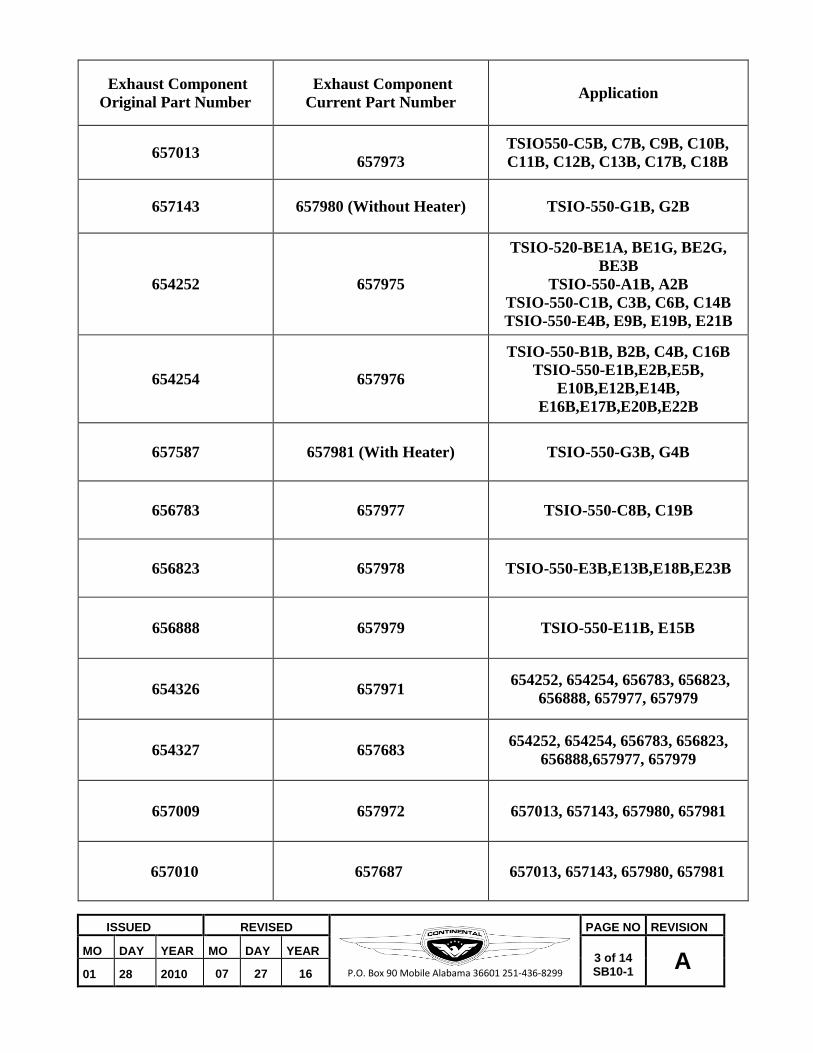
A list of current exhaust system assembly and component part numbers is included for information.
Failure to complete these inspection procedures can cause leakage of Carbon Monoxide (CO) gases into the nacelle and cabin area of the aircraft. Any leaks found in these
inspections must be repaired prior to further flight
WARNING

ISSUED REVISED
P.O. Box 90 Mobile Alabama 36601 251-436-8299
PAGE NO REVISION
MO DAY YEAR MO DAY YEAR 2 of 14 SB10-1 A
01 28 2010 07 27 16
Figure 1 Examples of transition components requiring replacement
ISSUED REVISED
P.O. Box 90 Mobile Alabama 36601 251-436-8299
PAGE NO REVISION
MO DAY YEAR MO DAY YEAR 3 of 14 SB10-1 A
01 28 2010 07 27 16
Exhaust Component Original Part Number
Exhaust Component Current Part Number
Application
657013
657973
TSIO550-C5B, C7B, C9B, C10B, C11B, C12B, C13B, C17B, C18B
657143
657980 (Without Heater)
TSIO-550-G1B, G2B
654252
657975
TSIO-520-BE1A, BE1G, BE2G, BE3B
TSIO-550-A1B, A2B TSIO-550-C1B, C3B, C6B, C14B TSIO-550-E4B, E9B, E19B, E21B
654254
657976
TSIO-550-B1B, B2B, C4B, C16B TSIO-550-E1B,E2B,E5B,
E10B,E12B,E14B, E16B,E17B,E20B,E22B
657587
657981 (With Heater)
TSIO-550-G3B, G4B
656783
657977
TSIO-550-C8B, C19B
656823
657978
TSIO-550-E3B,E13B,E18B,E23B
656888
657979
TSIO-550-E11B, E15B
654326
657971 654252, 654254, 656783, 656823,
656888, 657977, 657979
654327
657683 654252, 654254, 656783, 656823,
656888,657977, 657979
657009
657972
657013, 657143, 657980, 657981
657010
657687
657013, 657143, 657980, 657981
ISSUED REVISED
P.O. Box 90 Mobile Alabama 36601 251-436-8299
PAGE NO REVISION
MO DAY YEAR MO DAY YEAR 4 of 14 SB10-1 A
01 28 2010 07 27 16
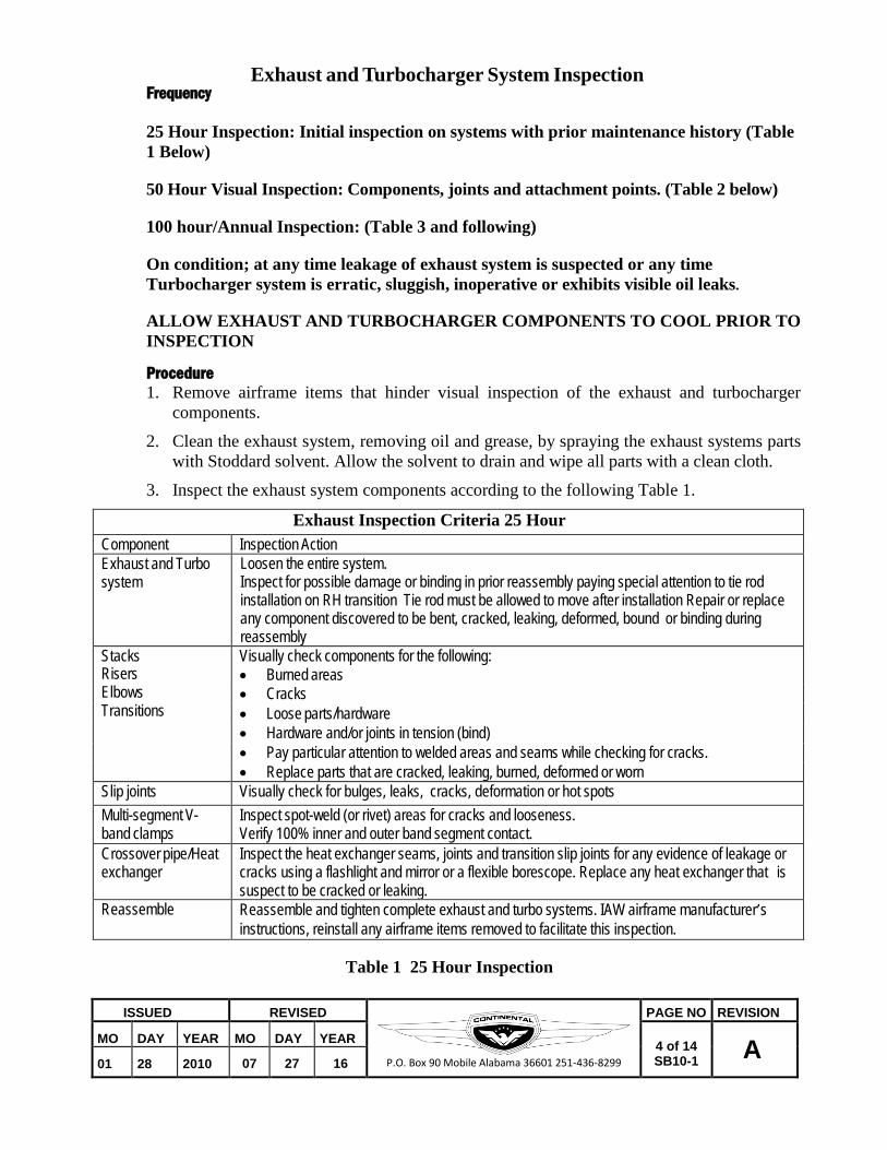
Frequency
Exhaust and Turbocharger System Inspection
25 Hour Inspection: Initial inspection on systems with prior maintenance history (Table 1 Below)
50 Hour Visual Inspection: Components, joints and attachment points. (Table 2 below)
100 hour/Annual Inspection: (Table 3 and following)
On condition; at any time leakage of exhaust system is suspected or any time Turbocharger system is erratic, sluggish, inoperative or exhibits visible oil leaks.
ALLOW EXHAUST AND TURBOCHARGER COMPONENTS TO COOL PRIOR TO INSPECTION
Procedure 1. Remove airframe items that hinder visual inspection of the exhaust and turbocharger
components.
2. Clean the exhaust system, removing oil and grease, by spraying the exhaust systems parts with Stoddard solvent. Allow the solvent to drain and wipe all parts with a clean cloth.
3. Inspect the exhaust system components according to the following Table 1.
Exhaust Inspection Criteria 25 Hour Component Inspection Action Exhaust and Turbo system
Loosen the entire system. Inspect for possible damage or binding in prior reassembly paying special attention to tie rod installation on RH transition Tie rod must be allowed to move after installation Repair or replace any component discovered to be bent, cracked, leaking, deformed, bound or binding during reassembly
Stacks Visually check components for the following: Risers • Burned areas Elbows • Cracks Transitions • Loose parts/hardware
• Hardware and/or joints in tension (bind) • Pay particular attention to welded areas and seams while checking for cracks. • Replace parts that are cracked, leaking, burned, deformed or worn
Slip joints Visually check for bulges, leaks, cracks, deformation or hot spots Multi-segment V- band clamps
Inspect spot-weld (or rivet) areas for cracks and looseness. Verify 100% inner and outer band segment contact.
Crossover pipe/Heat exchanger
Inspect the heat exchanger seams, joints and transition slip joints for any evidence of leakage or cracks using a flashlight and mirror or a flexible borescope. Replace any heat exchanger that is suspect to be cracked or leaking.
Reassemble Reassemble and tighten complete exhaust and turbo systems. IAW airframe manufacturer’s instructions, reinstall any airframe items removed to facilitate this inspection.
Table 1 25 Hour Inspection

ISSUED REVISED
P.O. Box 90 Mobile Alabama 36601 251-436-8299
PAGE NO REVISION
MO DAY YEAR MO DAY YEAR 5 of 14 SB10-1 A
01 28 2010 07 27 16
CAUTION: The exhaust system requires freedom of movement for proper operation after installation. Ensure the bushing (Item 10 page 11) is properly installed in the tie rod to allow expansion movement and all exhaust system components have adequate clearance from surrounding objects during and after installation
Procedure
50 Hour Inspection
1. Remove airframe items that hinder visual inspection of the exhaust and turbocharger components.
2. Clean the exhaust system, removing oil and grease, by spraying the exhaust systems parts with Stoddard solvent. Allow the solvent to drain and wipe all parts with a clean cloth.
3. Inspect the exhaust system components according to the following Table 2.
Exhaust Inspection Criteria 50 Hour
Component Inspection Action Stacks Visually inspect all components for the following: Risers • Burned areas Elbows • Cracks, Leaks Transitions • Loose parts/hardware
• Hardware and/or joints in tension (bind) • Pay particular attention to welded areas and seams while checking for cracks and leakage • Replace parts that are leaking, cracked, burned, deformed or worn
Slip joints Check for leaks, bulges, cracks, deformation or hot spots
Multi-segment V- band clamps
• Inspect spot-weld (or rivet) areas for cracks and looseness. • Inspect the corner radii of clamp inner segments for cracks with a flashlight and mirror. • Inspect the clamp outer band for flatness, especially within 2 inches of spot-weld tabs that
retain the T-bolt fastener – variance to flat must be less than 0.062 inches.
Crossover pipe/Heat exchanger
Inspect the heat exchanger seams, joints and transition slip joints for any evidence of leakage or cracks using a flashlight and mirror or a flexible borescope. Replace any heat exchanger that is suspect to be cracked or leaking.
Reassemble IAW airframe manufacturer’s instructions, reassemble any airframe items removed to facilitate this inspection
Table 2 50 Hour Inspection

ISSUED REVISED
P.O. Box 90 Mobile Alabama 36601 251-436-8299
PAGE NO REVISION
MO DAY YEAR MO DAY YEAR 6 of 14 SB10-1 A
01 28 2010 07 27 16
CAUTION: The exhaust system requires freedom of movement for proper operation after installation. Ensure the bushing (Item 10 page 11) is properly installed in the tie rod to allow expansion movement and all exhaust system components have adequate clearance from surrounding objects during and after installation
100 hour/Annual Inspection
Procedure 1. Remove airframe items that hinder visual inspection of the exhaust and turbocharger
components.
2. Clean the exhaust system, removing oil and grease, by spraying the exhaust systems parts with Stoddard solvent. Allow the solvent to drain and wipe all parts with a clean cloth.
3. Inspect the exhaust system components according to the following Table 3 and following.
Exhaust Inspection Criteria 100 Hour/Annual
Component Inspection Action Stacks Visually inspect all components for the following: Risers • Burned areas Elbows • Cracks Transitions • Loose parts/hardware
• Hardware and/or joints in tension (bind) • Pay particular attention to welded areas and seams while checking for cracks. • Replace parts that are cracked, burned, deformed or worn
Slip joints Check for bulges, cracks, deformation or hot spots
Multi-segment V- band clamps
• Inspect spot-weld (or rivet) areas for cracks and looseness. • Inspect the corner radii of clamp inner segments for cracks with a flashlight and mirror. • Inspect the clamp outer band for flatness, especially within 2 inches of spot-weld tabs that
retain the T-bolt fastener – variance to flat must be less than 0.062 inches.
Crossover pipe/Heat exchanger
Inspect the heat exchanger seams, joints and transition slip joints for any evidence of leakage or cracks using a flashlight and mirror or a flexible borescope. Replace any heat exchanger that is suspect to be cracked or leaking.
Reassemble IAW airframe manufacturer’s instructions reassemble any airframe items removed to facilitate this inspection
Table 3 100 Hour/Annual Inspection

ISSUED REVISED
P.O. Box 90 Mobile Alabama 36601 251-436-8299
PAGE NO REVISION
MO DAY YEAR MO DAY YEAR 7 of 14 SB10-1 A
01 28 2010 07 27 16
SLIP JOINTS
INSPECT FOR CRACKS, BULGES, OR HOT SPOTS
Connect a high volume, dust-free forced air source to the exhaust tailpipe outlet(s).
4. Apply approximately 5 psi of air pressure to the exhaust system.
5. Apply soap and water solution (ex; liquid dish washing soap and water solution with sufficient soap in water to produce bubbles in the solution when crack is located) to the entire exhaust system and check for air bubbling. If bubbling is found, examine components for cracks, security and overall condition. Check for any loose or leaking slip joints. Replace any cracked, worn, deformed or leaking exhaust components according to instructions that follow. Visually inspect the exhaust components and transition units for wear, leaks, cracks, or distortion. Replace any worn, leaking, cracked, or deformed exhaust system components. Inspect the exhaust riser connections at the cylinders to verify the condition of the exhaust flange, sealing of the gasket and exhaust manifold fastener security.
Exhaust Slip Joint Inspection
Figure 1
Exhaust system weld repairs may only be performed by an FAA Approved repair facility certified to perform specific weld repairs
Cracks in the exhaust system can release carbon monoxide into the nacelle or the cabin area; correct any exhaust leaks prior to further flight.
WARNING
WARNING
SLIP JOINTS
INSPECT FOR CRACKS, BULGES, OR HOT SPOTS

ISSUED REVISED
P.O. Box 90 Mobile Alabama 36601 251-436-8299
PAGE NO REVISION
MO DAY YEAR MO DAY YEAR 8 of 14 SB10-1 A
01 28 2010 07 27 16
V-band Clamp Inspection Figure 2
6. Replace worn, leaking, cracked, or distorted parts according to the criteria in Tables 1-3 and appropriate Engine Maintenance and Overhaul Manual.
7.` Remove and inspect the multi-segment V-band clamps:
CAUTION: Stretching the V-band clamp excessively will cause undue stress on the outer band and lead to V-band clamp fracture or failure.
a. Allow the engine (and exhaust system) to cool prior to commencing exhaust system removal to avoid burn injuries.
b. If the left tailpipe is to be removed, remove the four bolts, washers, and lock nuts connecting the tailpipe to the wastegate. Remove and discard the gasket and lock nuts.
c. Remove the safety wire and nut from the V-band clamp. Gently spread the V-band clamp and work the edges away from the turbocharger flange, onto the heater muff/tailpipe flange. Remove the heater muff/tailpipe.
d. Gently spread the V-band clamp over the removed exhaust flange.
e. Clean the outer band of the multi-segment V-band clamps with crocus cloth. Inspect the V-band clamps according to the instructions in Table 1. Replace the V-band clamp if it fails inspection criteria.
8. Inspect the turbocharger oil reservoirs, oil inlet and outlet fittings and surrounding area for signs of leakage. Torque fasteners or fittings to specifications contained in the latest revision of M-0, Standard Practice Maintenance Manual or replace leaking parts, as required to remedy leaking reservoirs or fittings.
9. Remove the induction air supply from the turbocharger compressor according to the airframe manufacturer’s instructions. Inspect the induction air supply duct for wear, deformation, cracks or other physical damage; replace, if necessary.

ISSUED REVISED
P.O. Box 90 Mobile Alabama 36601 251-436-8299
PAGE NO REVISION
MO DAY YEAR MO DAY YEAR 9 of 14 SB10-1 A
01 28 2010 07 27 16
10. Reassemble the turbocharger and exhaust system. a. Install the induction system air supply according to airframe manufacturer’s
instructions.
b. Connect the turbocharger compressor discharge to the aftercooler assembly with serviceable hose and induction tube clamps.
c. Spread a serviceable V-band clamp over the face of the turbocharger flange in a twisting motion.
d. Mate the exhaust tailpipe (or heater muff) and turbocharger flanges.
e. Gently spread the V-band clamp over the face of the tailpipe/heater muff flange in a twisting motion to center the V-band clamp evenly over the turbocharger and exhaust tailpipe flanges. Initially torque the clamp nut to half the amount specified in the latest revision of M-0, Standard Practice Maintenance Manual.
f. Use a rawhide or plastic mallet to lightly tap the outer edge of the clamp to distribute the load. Align the flanges and torque the clamp to the final torque value of the clamp specified in the latest revision of M-0, Standard Practice Maintenance Manual. Safety wire the V-band clamp from the T-bolt side of the clamp to the exposed t-bolt threads according to instructions.
NOTE: TSIO-550-G V-band clamps are riveted instead of welded.
Torque nut to specification plus nut running torque and secure V-Band clamp fastener with Ø .032 safety wire.
V-Band Clamp Safety Wire
ISSUED REVISED
P.O. Box 90 Mobile Alabama 36601 251-436-8299
PAGE NO REVISION
MO DAY YEAR MO DAY YEAR 10 of 14 SB10-1 A
01 28 2010 07 27 16
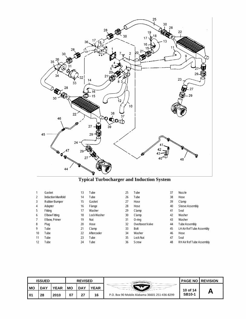
Typical Turbocharger and Induction System
1 Gasket 13 Tube 25 Tube 37 Nozzle 2 Induction Manifold 14 Tube 26 Tube 38 Hose 3 Rubber Bumper 15 Gasket 27 Hose 39 Clamp 4 Adapter 16 Flange 28 Hose 40 Sleeve Assembly 5 Fitting 17 Washer 29 Clamp 41 Seal 6 Elbow Fitting 18 Lock Washer 30 Clamp 42 Washer 7 Elbow, Primer 19 Nut 31 O-ring 43 Washer 8 Plug 20 Hose 32 Overboost Valve 44 Tube Assembly 9 Tube 21 Clamp 33 Bolt 45 LH Air Ref Tube Assembly 10 Tube 22 Aftercooler 34 Washer 46 Hose 11 Tube 23 Tube 35 Lock Nut 47 Seal 12 Tube 24 Tube 36 Screw 48 RH Air Ref Tube Assembly

ISSUED REVISED
P.O. Box 90 Mobile Alabama 36601 251-436-8299
PAGE NO REVISION
MO DAY YEAR MO DAY YEAR 11 of 14 SB10-1 A
01 28 2010 07 27 16
BUSHING ELONGATED
HOLE 8A
15B
14A, 15A
14C, 15C
Typical Turbocharger and Exhaust System
1 Elbow 13 Nut 22 Plug 35 Hose 2 Elbow 14 Contoured Tailpipe 23 Gasket 36 Hose 3 Tee 14A Inverse Tailpipe Option 24 Turbocharger 37 Hose 4 Tee 15 Contoured Tailpipe 25 Gasket 38 Elbow Fitting 5 Transition 15A Straight Tailpipe Option 26 Bolt 39 O-ring 6 Transition 15B Heater Muff 27 Washer 40 Elbow Fitting 7 Riser 15C Inverse Tailpipe Option 28 Lock Nut 41 O-ring 8 Crossover 16 V-band clamp 29 Support Bracket 42 Adapter 8A Crossover w/Heater Option 17 Gasket 30 Support Bracket 43 O-ring 9 Transition 18 Wastegate 31 Screw 44 Elbow Fitting 10 Bushing 19 Bolt 32 Washer 45 Adapter 11 Tie Rod 20 Washer 33 Lock Nut 46 Reducer 12 Bolt 21 Lock Nut 34 Controller

ISSUED REVISED
P.O. Box 90 Mobile Alabama 36601 251-436-8299
PAGE NO REVISION
MO DAY YEAR MO DAY YEAR 12 of 14 SB10-1 A
01 28 2010 07 27 16
Turbocharger and Exhaust System Installation
Procedure 1. Install risers (7) on the exhaust transitions (5 and 6). Apply 646943 antiseize compound
on all slip joints.
2. Slide the riser, tee, transition and flange assemblies (2, 3, 5, and 7) together to make up the 2-4-6 side collector assembly.
3. Slide the riser, tee, transition and flange assemblies (1, 4, 6 and 7) together to make up the 1-3-5 side collector assembly.
4. Install a new exhaust flange gasket (25) on each cylinder.
5. Carefully install the left and right side collectors on the cylinder exhaust ports; position the collector so the flanges mate with the risers and seat squarely on the ports; lubricate and install new lock nuts (21) on each cylinder flange- do not torque.
6. Install the turbochargers (24), mounted on the support brackets (29 and 30) on the turbo mount brackets (not shown); loosely install the mounting hardware with new lock nuts (33). This hardware will be torqued later in this procedure.
7. Install a new gasket (23) between the transitions (5 and 6) and the turbochargers (22 and 23). Hand-tighten the bolts and washers (26 and 27) with new lock nuts (28). This hardware will be torqued later in this procedure.
8. Loosely install the wastegate (18) between the tailpipe (14) and bypass transition assembly (9) positioned between two new gaskets (15) one gasket on top of the wastegate and one on the tailpipe mounting flange, using eight sets of fastening hardware (17 and 18) with new lock nuts (19). Fit this bypass transition assembly to the 2-4-6 side collector, transition and turbo. All this hardware will be torqued later in this procedure.
9. Slide the crossover (8) (or with heater if so equipped 8A) onto the slip joints of the 2-4-6 side bypass transition (9) and the 1-3-5 side transition (6). Check to assure that the crossover does NOT fit in a bind and slides smoothly onto the two slip joints (6 and 9).
10. Install the 1-3-5 side crossover to transition tie rod (11) with elongated hole matched with the transition and bushing. Install loosely to allow free movement of the tie rod and securing hardware (10, 12 and 13).
11. Place an exhaust flange v-band clamp (16) halfway onto each turbocharger exhaust flange.
12. Install the tailpipe (14) flange inside the clamp (16) mounted on the left side turbine exhaust flange.
13. Install the tailpipe flange (15) or heat exchanger flange (15A), if so equipped, inside the clamp (16) mounted on the right side turbine exhaust flange.
14. Assure that all components of the exhaust and turbocharger systems are correctly installed. Assure that 646943 anti-seize compound has been applied to all slip joints. Assure a loose fit to all components. Confirm that systems are installed with no misfit or bind in the completed installation. Any system misfit or binding must be corrected prior to applying the final torque to the components.

ISSUED REVISED
P.O. Box 90 Mobile Alabama 36601 251-436-8299
PAGE NO REVISION
MO DAY YEAR MO DAY YEAR 13 of 14 SB10-1 A
01 28 2010 07 27 16
15. Torque the support bracket screws (31) and nuts (33) to the latest revision of M-0, Standard Practice Maintenance Manual.
16. Torque the turbocharger riser bolts (26) and lock nuts (28) to the latest revision of M-0, Standard Practice Maintenance Manual.
17. Torque the exhaust flange nuts (21) to the latest revision of M-0, Standard Practice Maintenance Manual.
18. Secure the crossover assembly (8) on the transition (6) using the tie rod (11), bushing (10), nut (13) and bolt (12). Torque to the latest revision of M-0, Standard Practice Maintenance Manual. Check the installed assembly for freedom of movement and lack of binding.
CAUTION: The exhaust system requires freedom of movement for proper operation after installation. Ensure the bushing (10) is properly installed in the tie rod to allow expansion movement and all exhaust system components have adequate clearance from surrounding objects after installation
Torque nut to specification plus nut running torque and secure V-Band clamp fastener with Ø .032 safety wire.
V-Band Clamp Safety Wire Detail.
19. Reinstall airframe items, baffle pieces, electrical, sensors and cowling.
20. Run for test of exhaust and turbocharging systems.
21. After inspection is complete, make an appropriate log book entry for completion of this Service Bulletin, note time for next inspection and return aircraft to service.

ISSUED REVISED
P.O. Box 90 Mobile Alabama 36601 251-436-8299
PAGE NO REVISION
MO DAY YEAR MO DAY YEAR 14 of 14 SB10-1 A
01 28 2010 07 27 16
Intentionally Left Blank