service bulletin date: march, 2012 - keeping you safe · pdf fileu0100, u0101, u0102, u0109,...
TRANSCRIPT

Copyright 2012 General Motors LLC. All Rights Reserved.
Service Bulletin
File in Section: 07 - Transmission/Transaxle
Bulletin No.: 08-07-30-021G
Date: March, 2012
TECHNICAL
Subject: Loss of High Speed GMLAN Communications, Intermittent No Crank, IP GageFluctuation, Intermittent Door Lock Cycling, Intermittent Chime Operation, Various IPWarning Lamps Illuminated, Transmission May Not Shift, Communication DTCs U0073,U0100, U0101, U0102, U0109, U0121 or U0140 Set (Repair Terminals in TransmissionHarness Connector, Repair Open or Shorted GM High Speed LAN Circuits, Open orShorted Data Link Resistor, Corrosion or Poor Connections in Various Control ModuleConnectors)
Models: 2007–2010 Cadillac XLR2007–2012 Cadillac Escalade Models2009–2012 Cadillac Escalade Hybrid2007–2012 Chevrolet Avalanche, Corvette, Silverado, Suburban, Tahoe2008–2012 Chevrolet Silverado Hybrid, Tahoe Hybrid2007–2012 GMC Sierra, Yukon Models2008–2012 GMC Sierra Hybrid, Yukon Hybrid2008–2009 HUMMER H2Equipped With Gasoline Engine and 6 Speed Automatic Transmission 6L80 (RPO MYC)or 6L90 (RPO MYD)Equipped With Hybrid Propulsion (RPO HP2) and Two Mode 2ML70 AutomaticTransmission
This bulletin is being revised to add the 2012 model year and additional Correctioninformation. Please discard Corporate Bulletin Number 08-07-30-021F
(Section 07 – Transmission/Transaxle).
ConditionSome customers may comment on any of the followingconditions:• The malfunction indicator lamp (MIL) may be
illuminated.• Instrument panel cluster (IPC) warning lamps may
illuminate.• The transmission may not shift or defaults to
2nd gear.• The door locks may cycle by themselves.• The engine may not crank intermittently.• A driver information center (DIC) message may be
displayed.• The IPC gages may fluctuate.• Applying the brakes may cause the IPC to
become erratic and the chimes to operatesimultaneously.
Depending on the vehicle and build, technicians mayfind one or more, but not limited to the following, HighSpeed GMLAN Communication DTCs set as Current orHistory:• P0700: Transmission Control Module (TCM)
Requested MIL Illumination.• U0073: Control Module Communications
Bus OFF.• U0100: Lost Communication With ECM/PCM.• U0101: Lost Communication With Transmission
Control Module (TCM).• U0102: Lost Communication with Transfer Case
Control Module (TCCM).• U0109: Lost Communication With Fuel Pump
Control Module.• U0121: Lost Communication With ABS Control
Module.• U0140: Lost Communication With Body Control
Module (BCM).• U186B: Lost Communication With TCM.
SB-10043829-6448

Page 2 March, 2012 Bulletin No.: 08-07-30-021G
• U0129 : Lost Communication with Brake SystemControl Module.
• U186B: Lost Communication with TCM.• U0293: Lost Communication with HP2 Powertrain
Control Module.• U1862: Battery Energy Control Module Lost
Communication with Communications GatewayModule.
• U1886: Battery Energy Control Module LostCommunication with Engine ControlModule (ECM).
• U1888: Hybrid Powertrain Control Module LostCommunication With Starter/Generator ControlModule.
CauseThese conditions may be caused by, but not limited to,any of the following:• Chafed, damaged, pinched, open or shorted
wiring.• The terminal(s) for the High Speed GMLAN Serial
Data Bus has or have backed out of the 16-wayelectrical connector to the automatic transmission.
• The terminal position assurance (TPA) lock in thetransmission 16-way electrical connector is notfully seated.
• The High Speed GMLAN Serial Data Bus circuitsare open or shorted to ground.
• Corrosion in a control module connector.• Intermittent or poor connections in the inline
connectors containing the High Speed GMLANSerial Data Bus circuits.
• Water intrusion in a control module connector.Note: Model Year 2007 vehicles.
• The Terminator Resistor is open or shorted.Note: Model Year 2008 Sierra and Silverado vehicles.
• The Data Link Resistor is open or shorted.Note: Model Year 2009 and newer Sierra andSilverado vehicles.
• The Data Link Resistor 1 is open or shorted.Note: Model Year 2008 and newer Avalanche,Escalade, Tahoe, Yukon vehicles.
• The Data Link Resistor 1 is open or shorted.Note: Model Year 2008 and newer Hybrid RPO HP2vehicles.
• The Data Link Resistor 2 (RPO HP2) is open orshorted.
Note: The following cause only pertains to hybridRPO HP2 vehicles equipped with OnStar® DeleteRPO UE0.
• The High Speed GMLAN jumper harness loopconnector that plugs into the bottom rear of theinterior driver side junction block, is open orshorted from chafing on the IP brace.
Correction
Do This Don't Do This
Repair or replace anybacked out or damagedtransmission connectorterminal(s) as necessary.
DO NOT replace any controlmodule, wiring harness orcomponent until you have
first isolated the cause of thecondition or followed thisprocedure in its entirety.
Ensure that the transmissionconnector TPA is fully
seated (TPA is centered incheck window).
Repair the High SpeedGMLAN Serial Data Buscircuits that are open,
shorted to ground or havepoor connections.
Repair the corrosion orwater intrusion condition in
the affected moduleconnector.
Replace the TerminatorResistor that is open or
shorted.
Replace the Data LinkResistor 1 or Data LinkResistor 2 (RPO HP2
vehicles only) that is open orshorted.
Repair the junction blockjumper harness loop
connector wiring that is openor shorted. (RPO HP2Vehicles equipped with
OnStar® DeleteRPO UE0 Only).
Information for the Procedures toDiagnose and Repair the AboveConditions1. Perform the Diagnostic System Check-Vehicle
to begin your diagnosis.2. Perform a thorough visual inspection of the
vehicle.3. Depending on the vehicle and vehicle build,
some of the procedures may not be applicable.4. The following procedure is the only one
applicable to the Corvette and XLR.
Chafed Wiring Harness at TransmissionCase Retaining Clip and Inspection ofthe 16-way Electrical Connector forBacked Out Terminals1. Turn OFF the ignition and all accessories.2. Raise and support the vehicle. Refer to Lifting and
Jacking the Vehicle in SI.

Bulletin No.: 08-07-30-021G March, 2012 Page 3
2043302
2043303
3. Locate the 16-way electrical connector on the rightside of the automatic transmission as shown.
4. Inspect for chafed, damaged, pinched, open orshorted wiring within the conduit of the harnesswhere it is secured at the transmission by a metalattachment clip as shown. Inspect any wiringharness where these metal attachment clips areused on the vehicle as needed.
⇒ If the wiring is damaged, repair as needed.Refer to Power and Signal Distribution > WiringSystems and Power Management > DiagnosticInformation and Procedures in SI. Protect theconduit by covering any sharp edge with butyltape and the conduit and wiring harness withwoven polyester (PET) electrical tape. Securethe harness as needed.
2807959
5. Before disconnecting the 16-way connector,inspect for any backed out terminals (1) as shown.Fully seated terminals (2,3) are shown forcomparison.5.1. If a backed out terminal (1) is found, identify
the terminal(s) on the repair order.5.2. Look at the connector in order to identify the
number of the cavity with the backed outterminal. Refer to Wiring Systems and PowerManagement > Component Locator > MasterElectrical Component List in SI.
1921876
Note: For 2ML70 Only: Disconnect the 4WALelectrical connector.
Page 4 March, 2012 Bulletin No.: 08-07-30-021G
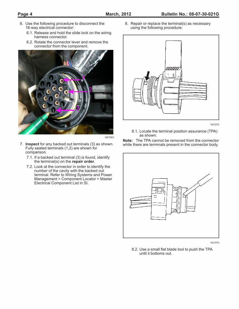
6. Use the following procedure to disconnect the16-way electrical connector:6.1. Release and hold the slide lock on the wiring
harness connector.6.2. Rotate the connector lever and remove the
connector from the component.
2807963
7. Inspect for any backed out terminals (3) as shown.Fully seated terminals (1,2) are shown forcomparison.7.1. If a backed out terminal (3) is found, identify
the terminal(s) on the repair order.7.2. Look at the connector in order to identify the
number of the cavity with the backed outterminal. Refer to Wiring Systems and PowerManagement > Component Locator > MasterElectrical Component List in SI.
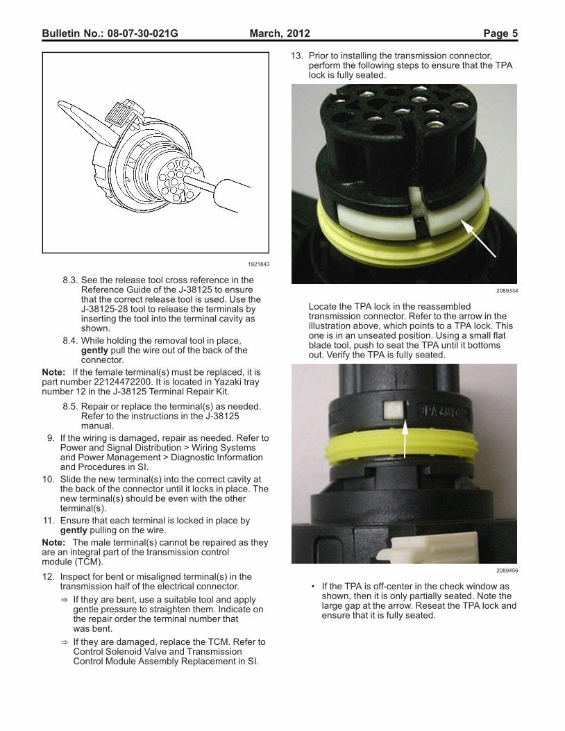
8. Repair or replace the terminal(s) as necessaryusing the following procedure:
1921872
8.1. Locate the terminal position assurance (TPA)as shown.
Note: The TPA cannot be removed from the connectorwhile there are terminals present in the connector body.
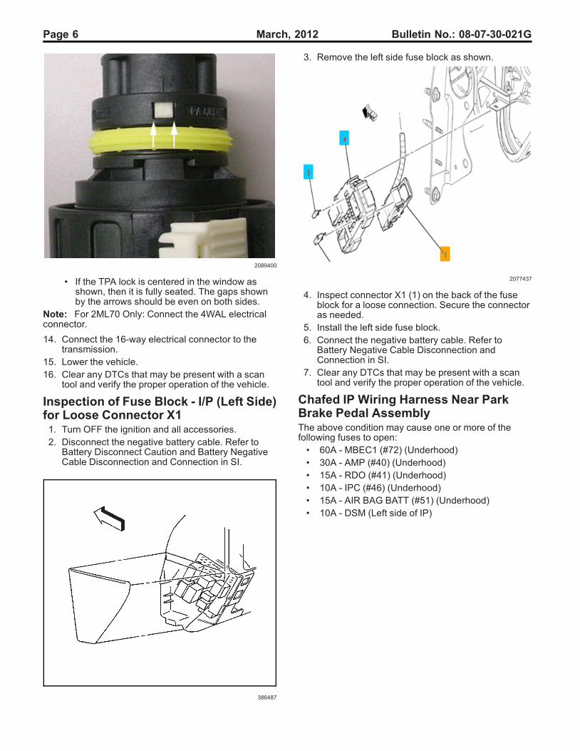
1921873
8.2. Use a small flat blade tool to push the TPAuntil it bottoms out.
Bulletin No.: 08-07-30-021G March, 2012 Page 5
1921843
8.3. See the release tool cross reference in theReference Guide of the J-38125 to ensurethat the correct release tool is used. Use theJ-38125-28 tool to release the terminals byinserting the tool into the terminal cavity asshown.
8.4. While holding the removal tool in place,gently pull the wire out of the back of theconnector.
Note: If the female terminal(s) must be replaced, it ispart number 22124472200. It is located in Yazaki traynumber 12 in the J-38125 Terminal Repair Kit.
8.5. Repair or replace the terminal(s) as needed.Refer to the instructions in the J-38125manual.
9. If the wiring is damaged, repair as needed. Refer toPower and Signal Distribution > Wiring Systemsand Power Management > Diagnostic Informationand Procedures in SI.
10. Slide the new terminal(s) into the correct cavity atthe back of the connector until it locks in place. Thenew terminal(s) should be even with the otherterminal(s).
11. Ensure that each terminal is locked in place bygently pulling on the wire.
Note: The male terminal(s) cannot be repaired as theyare an integral part of the transmission controlmodule (TCM).
12. Inspect for bent or misaligned terminal(s) in thetransmission half of the electrical connector.
⇒ If they are bent, use a suitable tool and applygentle pressure to straighten them. Indicate onthe repair order the terminal number thatwas bent.
⇒ If they are damaged, replace the TCM. Refer toControl Solenoid Valve and TransmissionControl Module Assembly Replacement in SI.
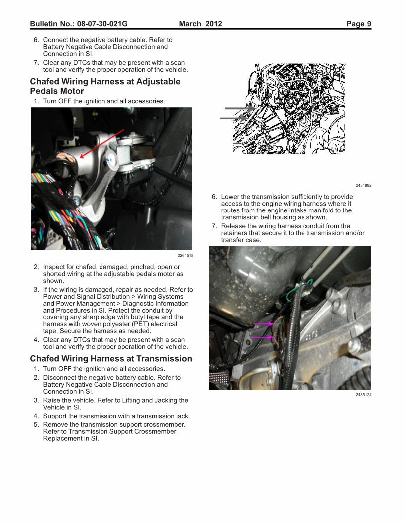
13. Prior to installing the transmission connector,perform the following steps to ensure that the TPAlock is fully seated.
2089334
Locate the TPA lock in the reassembledtransmission connector. Refer to the arrow in theillustration above, which points to a TPA lock. Thisone is in an unseated position. Using a small flatblade tool, push to seat the TPA until it bottomsout. Verify the TPA is fully seated.
2089456
• If the TPA is off-center in the check window asshown, then it is only partially seated. Note thelarge gap at the arrow. Reseat the TPA lock andensure that it is fully seated.
Page 6 March, 2012 Bulletin No.: 08-07-30-021G
2089400
• If the TPA lock is centered in the window asshown, then it is fully seated. The gaps shownby the arrows should be even on both sides.
Note: For 2ML70 Only: Connect the 4WAL electricalconnector.
14. Connect the 16-way electrical connector to thetransmission.
15. Lower the vehicle.16. Clear any DTCs that may be present with a scan
tool and verify the proper operation of the vehicle.
Inspection of Fuse Block - I/P (Left Side)for Loose Connector X11. Turn OFF the ignition and all accessories.2. Disconnect the negative battery cable. Refer to
Battery Disconnect Caution and Battery NegativeCable Disconnection and Connection in SI.
386487
3. Remove the left side fuse block as shown.
2077437
4. Inspect connector X1 (1) on the back of the fuseblock for a loose connection. Secure the connectoras needed.
5. Install the left side fuse block.6. Connect the negative battery cable. Refer to
Battery Negative Cable Disconnection andConnection in SI.
7. Clear any DTCs that may be present with a scantool and verify the proper operation of the vehicle.
Chafed IP Wiring Harness Near ParkBrake Pedal AssemblyThe above condition may cause one or more of thefollowing fuses to open:• 60A - MBEC1 (#72) (Underhood)• 30A - AMP (#40) (Underhood)• 15A - RDO (#41) (Underhood)• 10A - IPC (#46) (Underhood)• 15A - AIR BAG BATT (#51) (Underhood)• 10A - DSM (Left side of IP)

Bulletin No.: 08-07-30-021G March, 2012 Page 7
Five areas of potential contact have been identified:
2002643
• The IP wiring branch to C202 may have beenrouted outboard of the junction block (left IP) andthe retaining clip (1) off the branch may not havebeen fully seated. Possible point of contact (2).
2002646
• The IP wiring branch to C202 may have beenpushed up and forward into the park brakeassembly and the retaining clip off the branch maynot have been fully seated. Possible points ofcontact (1, 2).
2002647
• The IP wiring branch to C202 may not have beensecured into place as the gray retaining clip (1) offthe branch was never seated.
2002648
• The IP harness may be in hard contact with thetop rear edge (1) of the park brake assembly.

Page 8 March, 2012 Bulletin No.: 08-07-30-021G
2002649
• When releasing the park brake pedal, the movingpart (1) at the end of the park brake release cablemay be coming into hard contact with the IPharness.
If a condition is suspected or found with one of thecircuits running to C1 or C2 of the junction block or tothe inline IP-to-body connector C202 or at any of theseareas of concern then remove the front driver side doorsill plate, driver side body hinge pillar trim panel, left IPouter trim cover and perform the following steps:1. Turn OFF the ignition and all accessories.2. Inspect the IP harness for chafed, damaged,
pinched, open or shorted wiring at the park brakepedal assembly. Refer to the potential damagepoints as shown in the photos - at the side and rearof the park brake assembly. Be advised thatdamage may be covered by electrical tape, orturned away and hid from view.
3. Engage and release the park brake several times.Observe the moving part at the end of the parkbrake release cable as it may contact and damagethe IP harness. Inspect the IP harness at thispossible contact point. Note that any damage maybe covered by electrical tape and/or hid from view.
⇒ If the wiring is damaged, repair as needed.Refer to Power and Signal Distribution > WiringSystems and Power Management > DiagnosticInformation and Procedures in SI. Protect theharness by covering any sharp edge with butyltape and the harness with woven polyester(PET) electrical tape.
Engage and release the park brake severaltimes. Verify the harness is no longer makingcontact with any sharp edge or point of the parkbrake assembly. If it is still making contact,route it away from the contact point and secureit with tie straps.
Proceed to Step 4.
2002644
4. Inspect how the IP branch to C202 is routed. Routethe harness as necessary to match the correctrouting in the photo as shown. In order to route theIP harness branch correctly (behind the junctionblock-left I/P), remove the cover from the junctionblock-left I/P and unseat the junction block from thebracket.
5. Disconnect C202. Route the harness so that it liesbetween the "goalposts" of the junction blockbracket. Seat the junction block to the bracket. Theharness will now be under the junction block.
6. Secure the harness by seating the grey offsetretaining clip to the dashmat (or brown "buddy clip"if present - usually on SUV's only).Reconnect C202.
7. Clear any DTCs that may be present with a scantool and verify the proper operation of the vehicle.
Chafed IP Wiring Harness at Left SideJunction Block Mounting Bracket1. Turn OFF the ignition and all accessories.2. Disconnect the negative battery cable. Refer to
Battery Negative Cable Disconnection andConnection in SI.
3. Remove the left side junction block. Refer toInstrument Panel Electrical Center or JunctionBlock Replacement - Left Side in SI.
4. Inspect for chafed, damaged, pinched, open orshorted wiring at the mounting bracket.
⇒ If the wiring is damaged, repair as needed.Refer to Power and Signal Distribution > WiringSystems and Power Management > DiagnosticInformation and Procedures in SI. Protect theharness by covering any sharp edge with butyltape and the harness with woven polyester(PET) electrical tape. Secure the harness asneeded.
5. Replace the left side junction block. Refer toInstrument Panel Electrical Center or JunctionBlock Replacement - Left Side in SI.
Bulletin No.: 08-07-30-021G March, 2012 Page 9
6. Connect the negative battery cable. Refer toBattery Negative Cable Disconnection andConnection in SI.
7. Clear any DTCs that may be present with a scantool and verify the proper operation of the vehicle.
Chafed Wiring Harness at AdjustablePedals Motor1. Turn OFF the ignition and all accessories.
2264518
2. Inspect for chafed, damaged, pinched, open orshorted wiring at the adjustable pedals motor asshown.
3. If the wiring is damaged, repair as needed. Refer toPower and Signal Distribution > Wiring Systemsand Power Management > Diagnostic Informationand Procedures in SI. Protect the conduit bycovering any sharp edge with butyl tape and theharness with woven polyester (PET) electricaltape. Secure the harness as needed.
4. Clear any DTCs that may be present with a scantool and verify the proper operation of the vehicle.
Chafed Wiring Harness at Transmission1. Turn OFF the ignition and all accessories.2. Disconnect the negative battery cable. Refer to
Battery Negative Cable Disconnection andConnection in SI.
3. Raise the vehicle. Refer to Lifting and Jacking theVehicle in SI.
4. Support the transmission with a transmission jack.5. Remove the transmission support crossmember.
Refer to Transmission Support CrossmemberReplacement in SI.
2434892
6. Lower the transmission sufficiently to provideaccess to the engine wiring harness where itroutes from the engine intake manifold to thetransmission bell housing as shown.
7. Release the wiring harness conduit from theretainers that secure it to the transmission and/ortransfer case.
2435124
Page 10 March, 2012 Bulletin No.: 08-07-30-021G
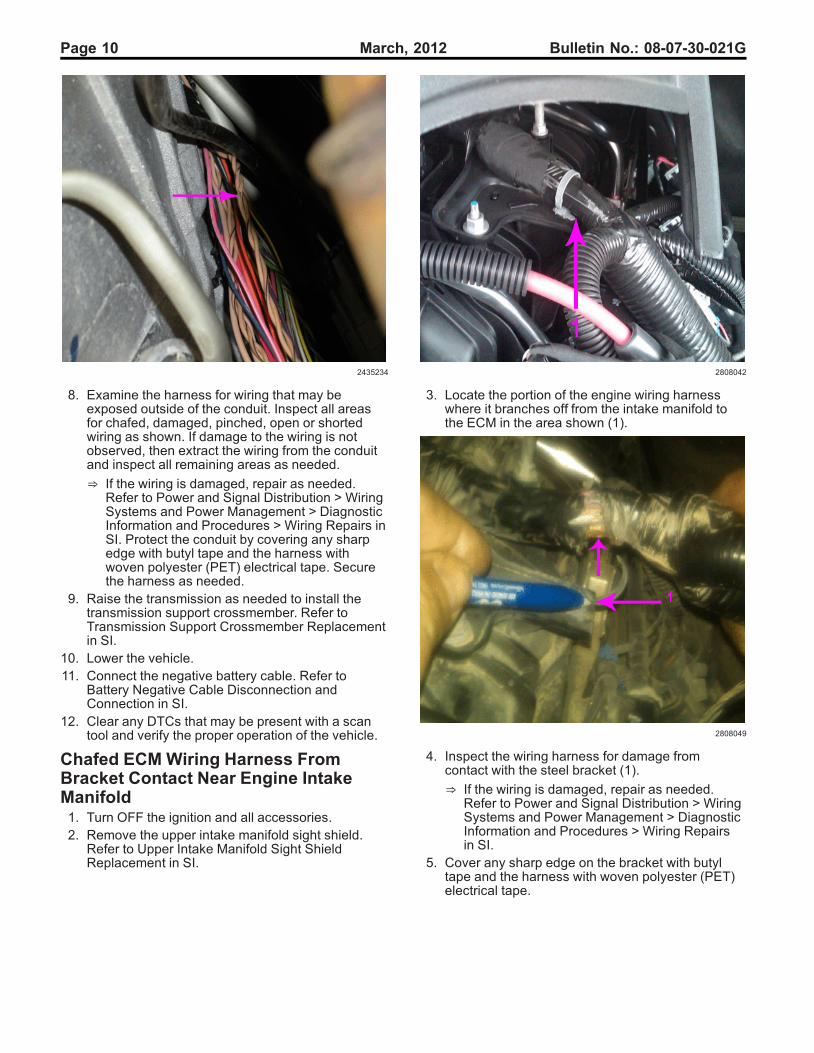
2435234
8. Examine the harness for wiring that may beexposed outside of the conduit. Inspect all areasfor chafed, damaged, pinched, open or shortedwiring as shown. If damage to the wiring is notobserved, then extract the wiring from the conduitand inspect all remaining areas as needed.
⇒ If the wiring is damaged, repair as needed.Refer to Power and Signal Distribution > WiringSystems and Power Management > DiagnosticInformation and Procedures > Wiring Repairs inSI. Protect the conduit by covering any sharpedge with butyl tape and the harness withwoven polyester (PET) electrical tape. Securethe harness as needed.
9. Raise the transmission as needed to install thetransmission support crossmember. Refer toTransmission Support Crossmember Replacementin SI.
10. Lower the vehicle.11. Connect the negative battery cable. Refer to
Battery Negative Cable Disconnection andConnection in SI.
12. Clear any DTCs that may be present with a scantool and verify the proper operation of the vehicle.
Chafed ECM Wiring Harness FromBracket Contact Near Engine IntakeManifold1. Turn OFF the ignition and all accessories.2. Remove the upper intake manifold sight shield.
Refer to Upper Intake Manifold Sight ShieldReplacement in SI.
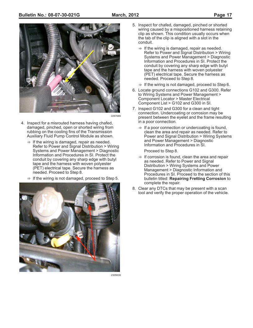
2808042
3. Locate the portion of the engine wiring harnesswhere it branches off from the intake manifold tothe ECM in the area shown (1).
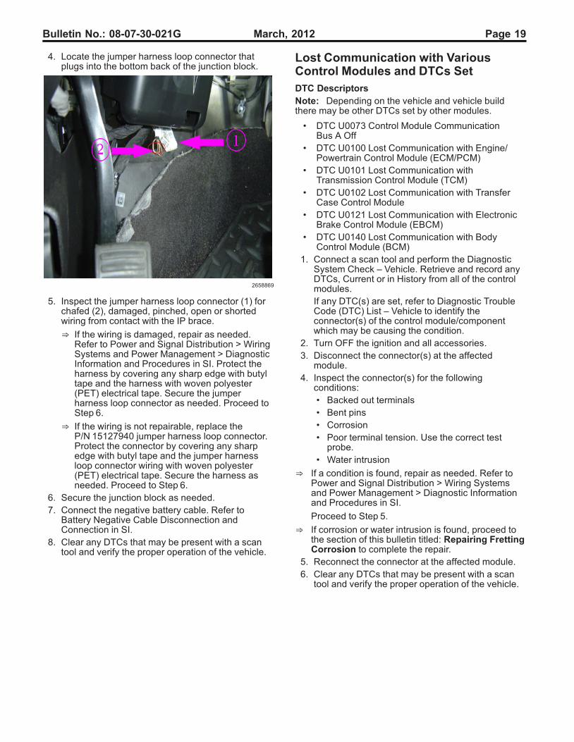
2808049
4. Inspect the wiring harness for damage fromcontact with the steel bracket (1).
⇒ If the wiring is damaged, repair as needed.Refer to Power and Signal Distribution > WiringSystems and Power Management > DiagnosticInformation and Procedures > Wiring Repairsin SI.
5. Cover any sharp edge on the bracket with butyltape and the harness with woven polyester (PET)electrical tape.

Bulletin No.: 08-07-30-021G March, 2012 Page 11
2808054
6. Protect the wiring harness by adding additionalconduit (2) as shown. Tape the conduit to theharness at both ends (1,3) to prevent movement.
7. Secure the harness to the bracket with a retainingclip (4) as needed.
Chafed Wiring Harness at Rear ofEngine Intake Manifold1. Turn OFF the ignition and all accessories.2. Remove the upper intake manifold sight shield.
Refer to Upper Intake Manifold Sight ShieldReplacement in SI.
2808697
3. Remove the retaining plate (2) that covers thewiring harness (1) on the top of the engine intakemanifold run channel.
2808687
4. Gently release and slightly raise the wiringharness (2) from the run channel (1) to allowsome slack in the harness.
2808134
5. Release the wiring harness conduit from theretainers that secure it to the rear of the engine andat the top of the transmission bell housing.

Page 12 March, 2012 Bulletin No.: 08-07-30-021G
2328025
Note: The engine intake manifold is shown removedto provide clarity.
6. Gently pull the wiring harness (2) up from the rearof the engine (1).
2328026
Inspect for chafed (1), damaged, pinched, open orshorted wiring. If damage is not observed, thenextract the wiring from the conduit and inspect allof the remaining areas as needed.
⇒ If the wiring is damaged, repair as needed.Refer to Power and Signal Distribution > WiringSystems and Power Management > DiagnosticInformation and Procedures.
7. Protect the conduit by covering any sharp edgeson the engine or transmission with butyl tape andthe harness with woven polyester (PET)electrical tape.
8. Secure the wiring harness within the conduit asneeded.
9. Attach the wiring harness conduit to the retainersthat secure it to the rear of the engine and at thetop of the transmission bell housing.
2808687
10. Secure the wiring harness (2) within the engineintake manifold run channel (1).
2808712
⇒ If the vehicle has a small engine wiring harnessbundle, secure a portion of the harness withinsome conduit (1) in the area that will be coveredby the retaining plate to prevent movement.
11. Tape both ends of the conduit (1) to the wiringharness.

Bulletin No.: 08-07-30-021G March, 2012 Page 13
2808697
12. Install and secure the retaining plate (2) over thetop of the wiring harness bundle (1).
13. Install the upper intake manifold sight shield.14. Clear any DTCs that may be present with a scan
tool and verify the proper operation of the vehicle.
Chafed Wiring Harness at ChassisBody Mounts Left Side Frame Rail1. Turn OFF the ignition and all accessories.2. Raise and support the vehicle. Refer to Lifting and
Jacking the Vehicle in SI.
2268656
3. Inspect the wiring harness along the left side framerail at the body mounts as shown for chafed,damaged, pinched, open or shorted wiring.
4. If the wiring is damaged, repair as needed. Refer toPower and Signal Distribution > Wiring Systemsand Power Management > Diagnostic Informationand Procedures. Protect the conduit by covering
any sharp edge with butyl tape and the harnesswith woven polyester (PET) electrical tape. Securethe harness as needed.
5. Lower the vehicle.6. Clear any DTCs that may be present with a scan
tool and verify the proper operation of the vehicle.
GMLAN Terminator Resistor 2007Vehicles1. Turn OFF the ignition and all accessories.2. Raise and support the vehicle. Refer to Lifting and
Jacking the Vehicle in SI.
Typical Location of Terminator Resistor (1)Short Wheel Base Vehicle
2653761
Typical Location of Terminator Resistor (1)Long Wheel Base Vehicle - RPO NQZ
2658551

Page 14 March, 2012 Bulletin No.: 08-07-30-021G
Typical Location of Terminator Resistor (1)Long Wheel Base Vehicle - Except RPO NQZ
2658600
Note: RPO NQZ Without Auxiliary Fuel Tank.
3. On the vehicle being serviced, observe the locationof the terminator resistor. Inspect the wiringharness leading to the terminator resistor, forchafed, damaged, pinched, open or shorted wiring.
⇒ If the wiring is damaged, repair as needed.Refer to Power and Signal Distribution > WiringSystems and Power Management > DiagnosticInformation and Procedures. Protect theconduit by covering any sharp edge with butyltape and the harness with woven polyester(PET) electrical tape. Secure the harness asneeded.
⇒ If the wiring is not damaged, proceed to Step 4.4. Disconnect the electrical connector from the
terminator resistor.5. Test the terminator resistor for 110–130Ω.
⇒ If the resistance is not within the specifiedrange, replace the terminator resistor andproceed to Step 6.
⇒ If the resistance is within the specified range,connect the electrical connector to theterminator resistor. Refer to Power and SignalDistribution > Data Communications > ScanTool Does Not Communicate with High SpeedGMLAN Device OR Diagnostic Trouble Code(DTC) List - Vehicle in SI.
6. Connect the electrical connector to the terminatorresistor. Secure the terminator resistor as needed.
7. Lower the vehicle.8. Clear any DTCs that may be present with a scan
tool and verify the proper operation of the vehicle.
Data Link Resistor 1 2009 Vehicles1. Turn OFF the ignition and all accessories.2. Raise and support the vehicle. Refer to Lifting and
Jacking the Vehicle in SI.
Typical Location of Data Link Resistor 1 (1)Short and Long Wheel Base Vehicles
2658245
Typical Location of Data Link Resistor 1 (1)Long Wheel Base HD Vehicles
2658490
3. On the vehicle being serviced, observe the locationof the data link resistor 1 (1). Inspect the wiringharness leading to the data link resistor 1, forchafed, damaged, pinched, open or shorted wiring.
⇒ If the wiring is damaged, repair as needed.Refer to Power and Signal Distribution > WiringSystems and Power Management > DiagnosticInformation and Procedures. Protect theconduit by covering any sharp edge with butyltape and the harness with woven polyester(PET) electrical tape. Secure the harness asneeded.
⇒ If damage is not found, proceed to Step 4.4. Disconnect the electrical connector from the data
link resistor 1.

Bulletin No.: 08-07-30-021G March, 2012 Page 15
5. Test the Data Link Resistor 1 for 110–130Ω.
⇒ If the resistance is not within the specifiedrange, replace the data link resistor 1 andproceed to Step 6.
⇒ If the resistance is within the specified range,connect the electrical connector to the data linkresistor 1. Refer to Power and SignalDistribution > Data Communications > ScanTool Does Not Communicate with High SpeedGMLAN Device OR Diagnostic Trouble Code(DTC) List - Vehicle in SI.
6. Connect the electrical connector to the data linkresistor 1. Secure the data link resistor 1 asneeded.
7. Lower the vehicle.8. Clear any DTCs that may be present with a scan
tool and verify the proper operation of the vehicle.
Rear Chassis Mounted Data LinkResistor 1 Chafed Wiring HarnessCausing Intermittent No/Crank and/orScan Tool Does Not Communicate withHigh Speed GMLAN Device1. Turn OFF the ignition and all accessories.2. Raise and support the vehicle. Refer to Lifting and
Jacking the Vehicle in SI.
2651339
3. Typical location of a data link resistor 1 (1)mounted on the rear of the chassis.
1991762
4. Inspect the wiring harness leading to the rear datalink resistor 1, between the truck box and frame forchafed, damaged, pinched, open or shorted wiringas shown.
⇒ If the wiring is damaged, repair as needed.Refer to Power and Signal Distribution > WiringSystems and Power Management > DiagnosticInformation and Procedures. Protect theconduit by covering any sharp edge with butyltape and the harness with woven polyester(PET) electrical tape. Secure the harness asneeded. Proceed to Step 9.
⇒ If the wiring is not damaged, proceed to Step 5.5. Disconnect the electrical connector from the data
link resistor 1.6. Test the data link resistor 1 for 110–130Ω.
⇒ If the resistance is not within the specifiedrange, replace the data link resistor 1 andproceed to Step 7.
⇒ If the resistance is within the specified range,connect the electrical connector to the data linkresistor 1. Refer to Power and SignalDistribution > Data Communications > ScanTool Does Not Communicate with High SpeedGMLAN Device OR Diagnostic Trouble Code(DTC) List - Vehicle in SI.
7. Connect the electrical connector to the data linkresistor 1. Secure the resistor as needed.
8. Protect the conduit by covering any sharp edgewith butyl tape and the harness with wovenpolyester (PET) electrical tape. Secure the harnessas needed.
9. Lower the vehicle.10. Clear any DTCs that may be present with a scan
tool and verify the proper operation of the vehicle.

Page 16 March, 2012 Bulletin No.: 08-07-30-021G
Inspection of Engine HarnessConnector X109 for Backed Out or BentTerminals and Poor Connections1. Turn OFF the ignition and all accessories.2. Locate the X109 connector. Refer to Wiring
Systems and Power Management > ComponentLocator > Master Electrical Component List > X109in SI.
2264519
3. Before disconnecting, verify the connector is fullyseated together even though the lever is lockeddown as shown.If the connector is not fully seated, repair asneeded. Refer to Power and Signal Distribution >Wiring Systems and Power Management >Diagnostic Information and Procedures >Connector Repairs in SI.
4. Inspect the connector for the following conditions:• Backed out terminals• Bent pins• Corrosion• Poor terminal tension (use the correct test
probe)
⇒ If a condition is found, repair as needed. Referto Power and Signal Distribution > WiringSystems and Power Management > DiagnosticInformation and Procedures in SI.
AND
⇒ If corrosion is found, proceed to the section ofthe bulletin titled: Repairing FrettingCorrosion to complete the repair.
5. Clear any DTCs that may be present with a scantool and verify the proper operation of the vehicle.
Inspection of Engine HarnessConnector X115 for Backed Out or BentTerminals and Poor Connections1. Turn OFF the ignition and all accessories.2. Locate the X115 connector. Refer to Wiring
Systems and Power Management > ComponentLocator > Master Electrical Component List > X115in SI.
3. Inspect the connector for the following conditions:• Backed out terminals• Bent pins• Corrosion• Poor terminal fit (use the correct test probe)
⇒ If a condition is found, repair as needed. Referto Wiring Systems and Power Management >Diagnostic Information and Procedures in SI.
AND
⇒ If corrosion is found, proceed to the section ofthe bulletin titled: Repairing FrettingCorrosion to complete the repair.
4. Clear any DTCs that may be present with a scantool and verify the proper operation of the vehicle.
Hybrid Models (HP2) Chafed WiringHarness Locations and Inspection ofEngine Harness Connector X150 forBacked Out Terminals and/or PoorConnections at Ground Locations G102and G3001. Turn OFF the ignition and all accessories.2. Locate the X150 connector. Refer to Wiring
Systems and Power Management > ComponentLocator > Master Electrical Component List > X150in SI.
3. Inspect the connector for the following conditions:• Backed out terminals• Bent pins• Corrosion• Poor terminal fit (use the correct test probe)
⇒ If a condition is found, repair as needed. Referto Power and Signal Distribution > WiringSystems and Power Management > DiagnosticInformation and Procedures in SI.
AND
⇒ If corrosion is found, proceed to the section ofthis bulletin titled: Repairing FrettingCorrosion to complete the repair.
⇒ If a condition or corrosion is not found, proceedto Step 4.
Bulletin No.: 08-07-30-021G March, 2012 Page 17
2297689
4. Inspect for a misrouted harness having chafed,damaged, pinched, open or shorted wiring fromrubbing on the cooling fins of the TransmissionAuxiliary Fluid Pump Control Module as shown.
⇒ If the wiring is damaged, repair as needed.Refer to Power and Signal Distribution > WiringSystems and Power Management > DiagnosticInformation and Procedures in SI. Protect theconduit by covering any sharp edge with butyltape and the harness with woven polyester(PET) electrical tape. Secure the harness asneeded. Proceed to Step 8.
⇒ If the wiring is not damaged, proceed to Step 5.
2305639
5. Inspect for chafed, damaged, pinched or shortedwiring caused by a mispositioned harness retainingclip as shown. This condition usually occurs whenthe tab of the clip is aligned with a slot in theconduit.
⇒ If the wiring is damaged, repair as needed.Refer to Power and Signal Distribution > WiringSystems and Power Management > DiagnosticInformation and Procedures in SI. Protect theconduit by covering any sharp edge with butyltape and the harness with woven polyester(PET) electrical tape. Secure the harness asneeded. Proceed to Step 8.
⇒ If the wiring is not damaged, proceed to Step 6.6. Locate ground connections G102 and G300. Refer
to Wiring Systems and Power Management >Component Locator > Master ElectricalComponent List > G102 and G300 in SI.
7. Inspect G102 and G300 for a clean and tightconnection. Undercoating or corrosion may bepresent between the eyelet and the frame resultingin a poor connection.
⇒ If a poor connection or undercoating is found,clean the area and repair as needed. Refer toPower and Signal Distribution > Wiring Systemsand Power Management > DiagnosticInformation and Procedures in SI.
Proceed to Step 8.
⇒ If corrosion is found, clean the area and repairas needed. Refer to Power and SignalDistribution > Wiring Systems and PowerManagement > Diagnostic Information andProcedures in SI. Proceed to the section of thisbulletin titled: Repairing Fretting Corrosion tocomplete the repair.
8. Clear any DTCs that may be present with a scantool and verify the proper operation of the vehicle.

Page 18 March, 2012 Bulletin No.: 08-07-30-021G
Hybrid Models (RPO HP2) Data LinkResistor 21. Turn OFF the ignition and all accessories.
2652658
2. Inspect the harness leading to the data linkresistor 2 (1) for chafed, damaged, pinched, openor shorted wiring. Refer to Power and SignalDistribution > Data Communications > Schematicand Routing Diagrams > Data CommunicationSchematics.
⇒ If the wiring is damaged, repair as needed.Refer to Power and Signal Distribution > WiringSystems and Power Management > DiagnosticInformation and Procedures. Protect theconduit by covering any sharp edge with butyltape and the harness with woven polyester(PET) electrical tape. Secure the harness asneeded.
⇒ If the wiring is not damaged, proceed to Step 3.3. Disconnect the electrical connector from the data
link resistor 2.4. Test the data link resistor 2 for 110–130Ω.
⇒ If the resistance is not within the specifiedrange, replace the data link resistor 2 andproceed to Step 5.
⇒ If the resistance is within the specified range,connect the electrical connector to theterminator resistor. Refer to Power and SignalDistribution > Data Communications > ScanTool Does Not Communicate with High SpeedGMLAN Device OR Diagnostic Trouble Code(DTC) List - Vehicle in SI.
5. Connect the electrical connector to the data linkresistor 2. Secure the resistor as needed.
6. Clear any DTCs that may be present with a scantool and verify the proper operation of the vehicle.
Hybrid Models (HP2) Equipped WithOnStar® Delete RPO UE0— IP JunctionBlock Jumper Harness Loop ConnectorChafed WiringVarious Symptoms and/or Powertrain andCommunication DTCs Set
The following is a list of some of the DTCs that may beset and is not all inclusive: C0242, P0700, P0AC4,U0293, U0100, U0109, U0129, U0140, U1862, U186B,U1886 or U1888.1. Turn OFF the ignition and all accessories.2. Disconnect the negative battery cable. Refer to
Battery Negative Cable Disconnection andConnection in SI.
2658675
3. Locate the junction block (1) on the driver side ofthe vehicle under the instrument panel (IP).
2658705
Bulletin No.: 08-07-30-021G March, 2012 Page 19
4. Locate the jumper harness loop connector thatplugs into the bottom back of the junction block.
2658869
5. Inspect the jumper harness loop connector (1) forchafed (2), damaged, pinched, open or shortedwiring from contact with the IP brace.
⇒ If the wiring is damaged, repair as needed.Refer to Power and Signal Distribution > WiringSystems and Power Management > DiagnosticInformation and Procedures in SI. Protect theharness by covering any sharp edge with butyltape and the harness with woven polyester(PET) electrical tape. Secure the jumperharness loop connector as needed. Proceed toStep 6.
⇒ If the wiring is not repairable, replace theP/N 15127940 jumper harness loop connector.Protect the connector by covering any sharpedge with butyl tape and the jumper harnessloop connector wiring with woven polyester(PET) electrical tape. Secure the harness asneeded. Proceed to Step 6.
6. Secure the junction block as needed.7. Connect the negative battery cable. Refer to
Battery Negative Cable Disconnection andConnection in SI.
8. Clear any DTCs that may be present with a scantool and verify the proper operation of the vehicle.
Lost Communication with VariousControl Modules and DTCs SetDTC DescriptorsNote: Depending on the vehicle and vehicle buildthere may be other DTCs set by other modules.
• DTC U0073 Control Module CommunicationBus A Off
• DTC U0100 Lost Communication with Engine/Powertrain Control Module (ECM/PCM)
• DTC U0101 Lost Communication withTransmission Control Module (TCM)
• DTC U0102 Lost Communication with TransferCase Control Module
• DTC U0121 Lost Communication with ElectronicBrake Control Module (EBCM)
• DTC U0140 Lost Communication with BodyControl Module (BCM)
1. Connect a scan tool and perform the DiagnosticSystem Check – Vehicle. Retrieve and record anyDTCs, Current or in History from all of the controlmodules.If any DTC(s) are set, refer to Diagnostic TroubleCode (DTC) List – Vehicle to identify theconnector(s) of the control module/componentwhich may be causing the condition.
2. Turn OFF the ignition and all accessories.3. Disconnect the connector(s) at the affected
module.4. Inspect the connector(s) for the following
conditions:• Backed out terminals• Bent pins• Corrosion• Poor terminal tension. Use the correct test
probe.• Water intrusion
⇒ If a condition is found, repair as needed. Refer toPower and Signal Distribution > Wiring Systemsand Power Management > Diagnostic Informationand Procedures in SI.
Proceed to Step 5.
⇒ If corrosion or water intrusion is found, proceed tothe section of this bulletin titled: Repairing FrettingCorrosion to complete the repair.
5. Reconnect the connector at the affected module.6. Clear any DTCs that may be present with a scan
tool and verify the proper operation of the vehicle.

Page 20 March, 2012 Bulletin No.: 08-07-30-021G
Inspection of Electronic SuspensionControl (ESC) Module Connector forMissing Weather Plugs in Not UsedCavities (RPO Z55 or G69)1. Turn OFF the ignition and all accessories.
Typical Location of ESC Module
2664329
2. Locate the ESC module (1).3. Disconnect the connector (2) at the ESC
module (1).
Typical View of Missing Weather Plug
2664512
4. Inspect the connector of the ESC module forweather plugs that are missing from: Not Usedcavities (1). Refer to > Power and SignalDistribution > Wiring Systems and PowerManagement > Component Locator > Master
Electrical Component List > Electronic SuspensionControl (ESC) Module > Connector End View for alist of cavities that are: Not Used.
⇒ If a weather plug is missing from any Not Usedcavity, repair as needed.
5. Install the connector (2) to the ESC module (1).6. Clear any DTCs that may be present with a scan
tool and verify the proper operation of the vehicle.
Repairing Fretting CorrosionNote: Fretting corrosion looks like little dark smudgeson the electrical terminals and appear where the actualelectrical contact is being made. In less severe cases itmay be unable to be seen or identified without the useof a magnifying glass.
1. If water intrusion is observed in the connector, usepressure regulated compressed air to dry it out.
2214281
2. DO NOTapply an excessive amount of dielectriclubricant as shown, to the connectors as hydrolockmay result when attempting to mate theconnectors. This could cause terminals to backout, resulting in an intermittent connection.
Important: Use ONLY a clean nylon brush that isDEDICATED to the repair of this specific condition.
Using a one-inch or smaller nylon bristle brush,apply dielectric lubricant P/N 12377900 (in CanadaP/N 10953529) to both the module or componentside and the harness side of the affectedconnectors.
3. Reconnect the affected connector(s) and wipeaway any excess lubricant that may be present.
4. If needed, connect the negative battery cable.Refer to Battery Negative Cable Disconnection andConnection in SI.
5. Clear any DTCs that may be present with a scantool and verify the proper operation of the vehicle.
OnStar is a registered trademark of the OnStarCorporation.

Bulletin No.: 08-07-30-021G March, 2012 Page 21
Parts Information
Part Number DescriptionMaterial
Allowance
22124472200J-38125 Terminal Repair
Kit, Yazaki Tray Number 12- Female Terminal
—
88988999 RESISTOR - DATA LINK —
12377900(in Canada,10953529)
Dielectric Lubricant(50 gram tube)
$11.56(USD)($2.90 perrepair)$17.35(CDN)($4.35 perrepair)
- Woven Polyester (PET)Electrical Tape
$22.72($3.00 perrepair)
Warranty InformationFor transmission electrical repairs please note in thetechnicians comments field on the repair order whichterminal number(s) were repaired or replaced. Also if amale terminal is bent (transmission side of connector),then indicate the bent terminal number on the repairorder.
For vehicles repaired under warranty, use:
LaborOperation Description
LaborTime
N6629(MY2009and Prior)
Wiring and/orConnector-Transmission –
Repair or Replace
UsePublishedLabor
OperationTime
N6616MY2009and Prior
Serial DATA/DLC/STARConnector Wiring and/orConnector Repair or
Replacement
N6620(MY2009and Prior)
Power and GroundsDistribution Wiring and/or
Connector Repair orReplacement
N6650(MY2010
and Newer)Terminal Replacement
N6653(MY2010
and Newer)Wire to Wire Repair
N6654(MY2010
and Newer)Connector Reconnection
N6656(MY2010
and Newer)
Ground Stud or Nut Repair orReplacement
N1736Block Assembly, Wiring
Harness Junction - Left Bodyand Instrument Panel Replace
N9613*Lubricate Body Control Module
(BCM) Connector WithDielectric Lubricant
0.1-0.3 hr
J7729*Lubricate Engine Control
Module (ECM) Connector WithDielectric Lubricant
K9534*Lubricate Transmission ControlModule (TCM) Connector With
Dielectric Lubricant
H9740*
Lubricate Electronic BrakeControl Module (EBCM)Connector With Dielectric
Lubricant
N9612* Lubricate “Other” ConnectorWith Dielectric Lubricant**
N9544* Repair and Reroute IP WireHarness Near Park Brake 0.8 hr
*This is a unique labor operation for bulletin use only. It willnot be published in the Labor Time Guide.
**You Must Document the Affected Connector on the RepairOrder.
Note: Any additional time for component R&R to gainaccess or for repair time greater than 0.3 hr must be
submitted as Other Labor Hours and requires appropriateauthorization and service management approval.
GM bulletins are intended for use by professional technicians, NOT a "do-it-yourselfer". They are written to inform thesetechnicians of conditions that may occur on some vehicles, or to provide information that could assist in the properservice of a vehicle. Properly trained technicians have the equipment, tools, safety instructions, and know-how to do ajob properly and safely. If a condition is described, DO NOT assume that the bulletin applies to your vehicle, or that yourvehicle will have that condition. See your GM dealer for information on whether your vehicle may benefit from theinformation.
WE SUPPORT VOLUNTARYTECHNICIAN
CERTIFICATION