series sc...d. boiler water quality & treatment: 1. excessive make-up water leaks in the system...
TRANSCRIPT

SC™
Gas/Oil Boilers
SeriesOil, Gas &
Installation, Operation & Maintenance Manual

USING THIS MANUAL 1 A. INSTALLATION SEQUENCE . . . . . . . . . . . . . . . . 1 B. SPECIAL ATTENTION BOXES . . . . . . . . . . . . . . 1
1. PREINSTALLATION 2 A. ACCESSIBILITY CLEARANCES . . . . . . . . . . . . . . 2 B. AIR FOR COMBUSTION & VENTILATION . . . . . 2 C. CHIMNEY & BREECHING . . . . . . . . . . . . . . . . . . 3 D. BOILER WATER QUALITY & TREATMENT . . . . 3
2. BOILER SET-UP 4 A. SETTING UP BOILER. . . . . . . . . . . . . . . . . . . . . . 4 B. ASSEMBLE FLUE COLLECTOR & SIDE CLEANOUT PLATE . . . . . . . . . . . . . . . . . . . 5 C. TANKLESS HEATER & REAR COVER PLATES . 5 D. HYDROSTATIC TEST THE BOILER . . . . . . . . . . 6
3. ASSEMBLE THE JACKET 7 JACKET ASSEMBLY . . . . . . . . . . . . . . . . . . . . . . 7
4. PIPE THE BOILER 8 A. PREPARATION . . . . . . . . . . . . . . . . . . . . . . . . . . 8 B. STEAM BOILER PIPING . . . . . . . . . . . . . . . . . . . 8 C. MULTIPLE STEAM BOILER INSTALLATIONS . . 8 D. NEAR BOILER PIPING SIZING - STEAM BOILERS . . . . . . . . . . . . . . . . . . . . . . . . . 8 E. WATER BOILER PIPING . . . . . . . . . . . . . . . . . . 14 F. LOW SYSTEM TEMPERATURE . . . . . . . . . . . . 14 G. CHILLED WATER SYSTEMS . . . . . . . . . . . . . . . 15 H. MULTIPLE BOILER INSTALLATIONS . . . . . . . . 15
5. VENTING 20 A. GENERAL . . . . . . . . . . . . . . . . . . . . . . . . . . . . . . 20 B. COMMON VENTING . . . . . . . . . . . . . . . . . . . . . 20
6. INSTALL THE BURNER 21 BURNER INSTALLATION . . . . . . . . . . . . . . . . . 21
7. CONNECT FUEL PIPING 22 A. GENERAL . . . . . . . . . . . . . . . . . . . . . . . . . . . . . . 22 B. INSTALL FUEL OIL PIPING . . . . . . . . . . . . . . . . 22 C. INSTALL GAS SUPPLY PIPING . . . . . . . . . . . . . 22 D. TEST GAS SUPPLY PIPING . . . . . . . . . . . . . . . 22
8. INSTALL CONTROLS & TRIM 24 A. CONTROLS . . . . . . . . . . . . . . . . . . . . . . . . . . . . 24 B. CONTROL WIRING . . . . . . . . . . . . . . . . . . . . . . 24
9. STARTING THE BOILER 30 A. CHECK THE PIPING . . . . . . . . . . . . . . . . . . . . . . 30 B1 FILL THE BOILER (WATER BOILERS) . . . . . . . . 30 B2 FILL THE BOILER (STEAM BOILERS . . . . . . . . 30 C. RUN BURNER CHECK-OUT . . . . . . . . . . . . . . . 30 D. CHECK BOILER CONTROLS . . . . . . . . . . . . . . . 31 E. CLEAN THE BOILER (STEAM BOILIERS ONLY) . . . . . . . . . . . . . . . . . 31
10. MAINTENANCE 32 A. PLACING BOILER IN OPERATION . . . . . . . . . . 33 B. TO SHUT DOWN THE BOILER . . . . . . . . . . . . . 33 C. MAINTENANCE – ANNUAL . . . . . . . . . . . . . . . 33 D. MONTHLY MAINTENANCE . . . . . . . . . . . . . . . 33 E. DAILY MAINTENANCE . . . . . . . . . . . . . . . . . . . 34 F. CLEANING HEATING SURFACES . . . . . . . . . . 34 G. CLEAN THE BOILER
(STEAM BOILERS ONLY) . . . . . . . . . . . . . . . . . 34
11. BOILER DIMENSIONS & RATINGS 35
12. REPAIR PARTS 38
13. STARTUP & SERVICE REPORT 40
TABLE OF CONTENTS
TABLE OF CONTENTS

A. INSTRUCTION MANUALSThe Series SC™ Installation, Operation & Maintenance Manual is divided into four basic sections:
1. Preinstallation (Section 1)2. Installation (Sections 2 through 8)3. Start-Up (Section 9)4. Maintenance (Section 10)
B. SPECIAL ATTENTION BOXESThroughout this manual you will see special attention boxes intended to supplement the instructions and make special notice of potential hazards. These categories mean, in the judgment of PB Heat, LLC:
USING THIS MANUAL
1
USING THIS MANUAL
Indicates a hazardous situation, which, if not avoided, will result in death or serious injury and major property damage.
⚠ DANGER
Indicates a hazardous situation, which, if not avoided, could result in death or serious injury and major property damage.
⚠ WARNING
Indicates special attention is needed, not related to personal injury or property damage.
NOTICE
⚠ CAUTIONIndicates a hazardous situation, which, if not avoided, could result in minor or moderate injury, and minor property damage.

A. CLEARANCES
The boiler must be installed in such a way that the gas/oil ignition system is protected from water (dripping, spraying, etc.) during operation and servicing.
B. AIR FOR COMBUSTION & VENTILATION
1. Be certain adequate facilities are available to provide air for satisfactory combustion and ventilation.
2. Appliances Located in Unconfined Spaces.a. Installations in unconfined spaces with
conventional construction and large areas such as basements, the supply of air for combustion and ventilation can usually be considered adequate.
3. Appliance Located in Confined Spacesa. If all air for combustion and ventilation is to come
from within the building, two openings, one near the ceiling and one near the floor of the boiler room shall be provided with the minimum free area of each opening equal to 140 sq. in. per gallon of oil burned.
b. If all air for combustion and ventilation is to come from outside the building, two openings, one near the ceiling and one near the floor of the boiler room shall be provided with the minimum free area of each opening equal to 35 sq. in. per gallon of oil burned.
If ducts are used to convey the air, areas of 35 sq. in. per gallon of oil burned for vertical ducts or 70 sq. in. per gallon of oil burned for horizontal ducts are to be provided. Ducts shall have the same area as the free area of the openings to which they are connected.
\
2
PREINSTALLATION
1. PREINSTALLATION
This equipment must be installed in accordance with installation requirements of the authority having jurisdiction or, in absence of such requirements, to the current edition of the National Fuel Gas Code ANSI Z223.1/NFPA 54; Chimneys, Fireplaces, Vents and Solid Fuel Appliances ANSI/NFPA 211; Standard for Installation of Oil Burning Equipment ANSI/NFPA 31 and in Canada Installation Code for Oil Burning Equipment CSA B139. Where required by the authority having jurisdiction, the installation must conform to Controls and Safety Devices for Automatically Fired Boilers ASME CSD-1.
NOTICE
Read carefully, study these instructions before beginning work. It will save time. Study the included drawings. Save these instructions for reference.
The boiler warranty can be voided if the boiler is not installed, maintained and serviced correctly.
This manual is intended for use by Qualified Heating Professionals only. Installation, service, or adjustmentof this heating appliance by anyone other than a Qualified Heating Professional may cause severe personalinjury, death, or major property damage.
WARNING
Table 1.1: Clearances from Jacket and Vent System
Required from Jacket to Combustible Construction
Recommended From Jacket for Accessibility and Mounting Controls
Top 5”* 24” if Left Side Clearance less than 24” (to clean flueways from top).
Front 16”* 16” from jacket due to burner.
Left 2”*
24” if Top Clearance less than 24” (to clean flueways from left side).
24” on steam with tankless coil.
9” in area of boiler service switch and junction box.
Right 2”* 2”
Rear 2”* 9” for mounting relief valve.
Vent Pipe (Single Wall) - 9” to Combustible Construction. Clearance may be reduced using methods in NFPA 31.Vent Pipe (Double Wall) - See Manufacturer’s Instructions.
* Consider also vent pipe clearance, including distance from edge of flue outlet to combustible construction (as applicable).

C. CHIMNEY & BREECHING
1. The Series SC™ boilers are designed for forced draft firing only. The boiler and flue outlet sizes produce the required pressures in the combustion chamber when operating at boiler rating. The boiler breeching should be the full size of the flue collector outlet and may be attached to a conventional chimney or a short vent. A 3 ft. minimum height of vent above the roof is required. DO NOT SIDEWALL VENT BOILER.
2. When attached to a conventional chimney an excess draft may be available. If such is the case, a draft regulator should be installed and set to provide minimum draft. The damper supplied should then be set to provide a maximum pressure of +0.1” water column or minimum of 0” water column at the outlet of the flue collector. Lock damper in place by use of set screws.
If the boiler breeching is attached to a non-conventional chimney or short stack the breeching also will be pressurized. Unsealed conventional smoke pipe must not be used as it will leak flue gases at the seams and joints.
When constructing a sealed or welded breeching for the Series SC™ boilers, a means of disconnecting (Flange) must be provided to facilitate removal of the flue collector for vertical cleaning of the boiler and chimney. Refer to Figure 1.1.
3. Install vent piping to slope upward at least ¼” per lineal foot (21mm per meter) for any horizontal run.
D. BOILER WATER QUALITY & TREATMENT
1. Excessive Make-up Water Leaks in the system must be repaired. Leaks increase the volume of make-up water, which significantly shortens the life of the boiler. Oxygen and chlorides in make-up water greatly accelerate corrosion of the cast iron sections. Minerals in make-up water precipitate when heated and adhere to the cast iron, which eventually overheats the iron and cause the iron to crack. Minerals in make-up water also create foam, which can interfere with proper operation of probe low water cutoffs.
If an automatic water feeder is installed, provide a means of detecting and alerting the user to excessive make-up water, such as a water feed counter.
2. Steam Boilersa. Boiler water pH should be in the 7.5 to 11 range.b. Boiler water chloride concentration should
be less than 30 ppm.c. The water hardness should be less than 7 grains
per gallon to prevent scale build-up and foaming.
3. Water Boilersa. Boiler water pH should be in the 7.5 to 11 range.b. Boiler water chloride concentration should
be less than 30 ppm.c. The water hardness should be less than 9 grains
per gallon to prevent scale build-up.
Consult a local qualified water treatment specialist for recommendations regarding the appropriate chemical compounds and concentrations which are compatible with local environmental regulations.
Boiler failure caused by excessive make-up water and poor water quality are not covered as manufacturing defects.
3
Figure 1.1: Vent System
PREINSTALLATION
4
BOILER SET-UP
2. BOILER SET-UP
A. SETTING UP BOILER
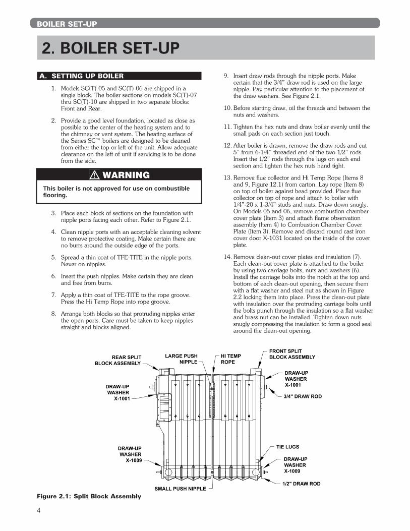
1. Models SC(T)-05 and SC(T)-06 are shipped in a single block. The boiler sections on models SC(T)-07 thru SC(T)-10 are shipped in two separate blocks: Front and Rear.
2. Provide a good level foundation, located as close as possible to the center of the heating system and to the chimney or vent system. The heating surface of the Series SC™ boilers are designed to be cleaned from either the top or left of the unit. Allow adequate clearance on the left of unit if servicing is to be done from the side.
3. Place each block of sections on the foundation with nipple ports facing each other. Refer to Figure 2.1.
4. Clean nipple ports with an acceptable cleaning solvent to remove protective coating. Make certain there are no burrs around the outside edge of the ports.
5. Spread a thin coat of TFE-TITE in the nipple ports. Never on nipples.
6. Insert the push nipples. Make certain they are clean and free from burrs.
7. Apply a thin coat of TFE-TITE to the rope groove. Press the Hi Temp Rope into rope groove.
8. Arrange both blocks so that protruding nipples enter the open ports. Care must be taken to keep nipples straight and blocks aligned.
9. Insert draw rods through the nipple ports. Make certain that the 3/4” draw rod is used on the large nipple. Pay particular attention to the placement of the draw washers. See Figure 2.1.
10. Before starting draw, oil the threads and between the nuts and washers.
11. Tighten the hex nuts and draw boiler evenly until the small pads on each section just touch.
12. After boiler is drawn, remove the draw rods and cut 5” from 6-1/4” threaded end of the two 1/2” rods. Insert the 1/2” rods through the lugs on each end section and tighten the hex nuts hand tight.
13. Remove flue collector and Hi Temp Rope (Items 8 and 9, Figure 12.1) from carton. Lay rope (Item 8) on top of boiler against bead provided. Place flue collector on top of rope and attach to boiler with 1/4”-20 x 1-3/4” studs and nuts. Draw down snugly. On Models 05 and 06, remove combustion chamber cover plate (Item 3) and attach flame observation assembly (Item 4) to Combustion Chamber Cover Plate (Item 3). Remove and discard round cast iron cover door X-1031 located on the inside of the cover plate.
14. Remove clean-out cover plates and insulation (7). Each clean-out cover plate is attached to the boiler by using two carriage bolts, nuts and washers (6). Install the carriage bolts into the notch at the top and bottom of each clean-out opening, then secure them with a flat washer and steel nut as shown in Figure 2.2 locking them into place. Press the clean-out plate with insulation over the protruding carriage bolts until the bolts punch through the insulation so a flat washer and brass nut can be installed. Tighten down nuts snugly compressing the insulation to form a good seal around the clean-out opening.
Figure 2.1: Split Block Assembly
This boiler is not approved for use on combustible flooring.
WARNING

5
BOILER SET-UP
B. ASSEMBLE THE FLUE COLLECTOR & SIDE CLEANOUT PLATE
1. Remove the flue collector and Hi-Temp Rope (Figure 12.1, items 8 and 9) from carton. Lay the rope (8) on top of the boiler against bead provided. Place flue collector on top of rope and attach with 1/4”-20 x 1-3/4” studs and nuts. Draw down snuggly. On models 05 and 06, remove burner plate (item 3) and attach the flame observation assembly (item 4) to the burner plate. Remove and discard round cast iron cover door X-1031 located on the inside of the burner plate observation opening.
2. Install Flue Rod Baffles in each flueway as shown in Figure 2.2.
3. Remove flue collector and insulation (Figure 12.1, item 7). Each cleanout cover plate is attached to the boiler by using two carriage bolts, nuts and washers (6). Install the carriage bolts into the notch at the top and bottom of each cleanout opening, then secure them with a flat washer and steel nut, as shown in Figure 2.3, locking them in place. Press the cleanout plate with insulation over the protruding carriage bolts until the bolts punch through the insulation so a flat washer and brass nut can be installed. Tighten down the nuts, snugly compressing the insulation to form a good seal around the cleanout opening.
C. TANKLESS HEATER OR COVER PLATE
1. If a tankless Heater is used (Item 13 or 17, Figure 12.1), install as pictured. On water boilers, install in the opening in the front section. On Steam boilers, install in the opening in the rear section. For suggested piping of tankless water heaters refer to Figures 2.4 and 2.5.
2. If not using a tankless heater, cover the heater opening with the cover plate (item 12 and 16, Figure 12.1).
3. See Table 2.1 for tankless coil ratings.
Figure 2.2: Flue Rod Baffle Locations
Figure 2.3: Cleanout Cover Assembly
Water heater ratings are based on intermittent demand—40°F to 140°F with 200°F boiler water temperature.*Used on water boilers only.
Table 2.1: Tankless Water Heater Ratings
Boiler Model
Number
Heater No.* X-1020 – G.P.M.
Heater No.* X-1022 – G.P.M.
Heater No. X-1082 – (Steam)
SC(T)-05 4.75 — 4.75
SC(T)-06 5.0 — 5.00
SC(T)-07 5.25 — 5.25
SC(T)-08 5.5 10.0 5.50
SC(T)-09 5.75 11.0 5.75
SC(T)-10 6.0 12.0 6.00

6
BOILER SET-UP
D. HYDROSTATIC TEST THE BOILER
1. Field assembled blocks must be tested for leaks at push nipples.
2. Install a Drain Valve.
3. Provide a water supply to the boiler and plug all unused tappings.
4. Fill the boiler with water and vent all of the air from the boiler.
5. Pressurize the boiler to 45 psig for sections that are stamped for a maximum allowable working pressure of 30 psi. For sections that are stamped for a 50 psi MAWP, pressurize the boiler to 75 psig. Check for leaks at joints and fittings.
6. Drain boiler and proceed with jacket assembly.
12" MIN.
3/4"CONTROLTAPPING
TANKLESSHEATER
HIGH TEMPERATUREHOT WATER
WATERMIXER
COLD WATER INLET
FLOW CONTROL
MIXEDWATER
Figure 2.4: Tankless Coil Piping, Steam Boiler
12" MIN.
3/4" CONTROLTAPPING
TANKLESSHEATER
HIGH TEMPERATUREHOT WATER
MIXEDWATER
WATERMIXER
COLD WATER INLET
FLOW CONTROL
Figure 2.5: Tankless Coil Piping, Water Boiler

7
JACKET ASSEMBLY
1. Refer to Figure 12.1 for exploded view. Attach the back jacket panel (item 19) to the bosses on the middle of the back section with two 1/4” x 3/8” truss head machine screws (item 20) provided. The back panel has two 5/16” dia. Holes close to the center of the panel.
2. Locate ceramic blanket liner and install in combustion chamber floor, placing the back edge of the blanket against the bottom edge of the target wall.
3. Place the front Jacket panel (item 23) on the block and attach the burner plate assembly (item 3)
4. Attach the right side jacket panel (item 22) to the front and back panels with sheet metal screws
5. If a tankless heater is used, remove the knock out piece in the left side jacket panel (item 21) before installing. Attach the left side jacket panel in the same manner as the right side panel.
6. Attach the top panel. The top panel is made in two pieces (item 24 & 25). Join the two pieces together with sheet metal screws. Secure the top panel to the front, back and sides with sheet metal screws.
On Series SCT models, the optional tankless heater (item 17) must be installed before the left side jacket panel is attached.
NOTICE
ASSEMBLE THE JACKET
3. ASSEMBLE THE JACKET

8
PIPE THE BOILER
4. PIPE THE BOILER
A. PREPARATION
1. Do not pipe the boiler until the jacket is installed. Use nipples long enough to extend through the jacket.
B. STEAM BOILER PIPING
1. Refer to the PB Heat, LLC Steam Installation Survey for guidance.
2. The return from the system should always enter the equalizer through the Hartford Loop, 2” to 4” below the normal water line (see dimensional drawing for normal water line).
3. See Table 4.1 for pipe size information.
4. Pipe the steam header a minimum of 24” above the normal water line using swing joints to attach the risers into the steam header.
5. Pipe the Header with an offset as shown in the drawings. This offset prevents the expansion and contraction of the Header from damaging the boiler sections.
6. Boiler Water Feeders (where used) - See Section 1 - Preinstallation, Part D - Boiler Water Quality and Treatment.
C. MULTIPLE STEAM BOILER INSTALLATION
1. Figure 4.1 shows typical piping for multiple boiler Gravity Return systems. Figure 4.2 shows typical piping for multiple boiler Pumped Return systems.
2. Provide separate feed lines for multiple boiler pumped return systems. Use either separate feed pumps or solenoid or motorized valves to isolate boilers. This is needed to provide reliable level control and avoid nuisance performance problems.
3. Condensate return units are not effective for multiple boiler installations since they do no respond to the needs of the boilers. Always use Boiler Feed Units.
4. Install a Float and Thermostatic trap at the boiler water level on each of the multiple boilers on a pumped return system. This prevents flooding of idle boilers due to condensation of steam.
D. NEAR BOILER PIPING SIZING - STEAM BOILERS
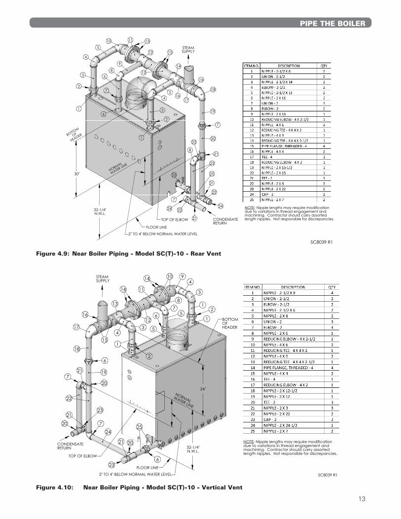
1. For Near Boiler Piping refer to Figures 4.3 through 4.10.
Table 4.1: Steam
Boiler Model Risers Header EqualizerSC(T)-05 2–2” 3” 1-1/2”SC(T)-06 2–2” 4” 1-1/2”SC(T)-07 2–2-1/2” 4” 1-1/2”SC(T)-08 2–2-1/2” 4” 1-1/2”SC(T)-09 2–2-1/2” 4” 2”SC(T)-10 2–2-1/2” and 1–2” 4” 2”
The return from system should always enter equalizer through Hartford Loop, 2” to 4” below normal water line.
Use swing joints to attach header to avoid damage to the boiler due to thermal expansion and contraction of the steam header pipe.
NOTICE
Always locate the Steam Supply take-off between the Equalizer and the last Boiler Riser. (See PB Heat, LLC’s “Steam Installation Survey” for discussion). Locating the steam supply between the risers (bull head tee), will cause water carryover to the system.
NOTICE
Do not reduce the size or number of risers shown in Table 4.1. These are required for reliable operation of the boiler. If the risers are undersized or incorrectly placed, a sloped water line can occur in the boiler, causing possible overheating of some sections.
NOTICE
Failure to maintain boiler water quality could result in a failed heat exchanger.
CAUTION

9
PIPE THE BOILER
Figure 4.1: Piping Multiple Boilers, Typical, Gravity Return Systems.
Figure 4.2: Piping Multiple Boilers, Typical, Pumped Return Systems

10
PIPE THE BOILER
STEAM SUPPLY
CONDENSATERETURN
29"
32-1/4"N.W.L.
FLOOR LINE
5
10
19
22
18
14
20
17
17
17
2315
19
21
19
21
NORMAL
WATER LINE
BOTTOM
OF
HEADER
TOP OF ELBOW
2
1
1
2
15
67
8
9
8
24
6
16
2" TO 4" BELOW NORMAL WATER LEVEL
4
4
4
4
3
3 11
12
13
SC8036 R1
NOTE: Nipple lengths may require modificationdue to variations in thread engagement andmachining. Contractor should carry assortedlength nipples. Not responsible for discrepancies.
Figure 4.3: Near Boiler Piping - Model SC(T)-07 - Rear Vent
STEAM SUPPLY
CONDENSATERETURN
10
19
22
18
14
20
17
17
17
23
15
1921
19
21
15
8
9
8
24
6
16
1
3
5
2
1
76
19
20
2
1
1
2" TO 4" BELOW NORMAL WATER LEVEL
4
4
11
12
13
TOP OF ELBOW
BOTTOM
OF
HEADER
NORMAL
WATER LINE
32-1/4"N.W.L.
NOTE: Nipple lengths may require modificationdue to variations in thread engagement andmachining. Contractor should carry assortedlength nipples. Not responsible for discrepancies.
FLOOR LINE
24"
SC8036 R1
Figure 4.4: Near Boiler Piping - Model SC(T)-07 - Vertical Vent

11
STEAM SUPPLY
CONDENSATERETURN
29"
32-1/4"N.W.L.
FLOOR LINE
5
10
19
22
18
14
20
17
17
17
2315
19
21
19
21
NORMAL
WATER LINE
BOTTOM
OF
HEADER
TOP OF ELBOW
2
1
1
2
15
67
8
9
8
24
6
16
2" TO 4" BELOW NORMAL WATER LEVEL
4
4
4
4
3
3 11
13
12
SC8037 R1
NOTE: Nipple lengths may require modificationdue to variations in thread engagement andmachining. Contractor should carry assortedlength nipples. Not responsible for discrepancies.
Figure 4.5: Near Boiler Piping - Model SC(T)-08 - Rear Vent
STEAM SUPPLY
CONDENSATERETURN
10
19
22
18
14
20
17
17
17
23
15
1921
19
21
15
8
9
8
24
6
16
1
3
5
2
1
76
19
20
2
1
1
2" TO 4" BELOW NORMAL WATER LEVEL
4
4
13
12
11
TOP OF ELBOW
BOTTOM
OF
HEADER
NORMAL
WATER LINE
32-1/4"N.W.L.
NOTE: Nipple lengths may require modificationdue to variations in thread engagement andmachining. Contractor should carry assortedlength nipples. Not responsible for discrepancies.
FLOOR LINE
24"
SC8037 R1
Figure 4.6: Near Boiler Piping - Model SC(T)-08 - Vertical Vent
PIPE THE BOILER

12
PIPE THE BOILER
STEAM SUPPLY
CONDENSATERETURN
30"
32-1/4"N.W.L.
FLOOR LINE
6
11
18
21
17
13
19
16
16
16
2114
18
20
18
20
NORMAL
WATER LINE
BOTTOM
OF
HEADER
TOP OF ELBOW
2
1
1
214
78
9
10
9
7
15
2" TO 4" BELOW NORMAL WATER LEVEL
3
3
5
5
4
4 12
SC8038 R1
NOTE: Nipple lengths may require modificationdue to variations in thread engagement andmachining. Contractor should carry assortedlength nipples. Not responsible for discrepancies.
Figure 4.7: Near Boiler Piping - Model SC(T)-09 - Rear Vent
STEAM SUPPLY
CONDENSATERETURN
10
17
20
16
12
18
15
15
15
20
13
1719
17
19
13
8
9
8
6
14
1
3
5
2
1
76
17
18
2
1
1
2" TO 4" BELOW NORMAL WATER LEVEL
4
4
11
TOP OF ELBOW
BOTTOM
OF
HEADER
NORMAL
WATER LINE
32-1/4"N.W.L.
NOTE: Nipple lengths may require modificationdue to variations in thread engagement andmachining. Contractor should carry assortedlength nipples. Not responsible for discrepancies.
FLOOR LINE
24"
SC8038 R1
Figure 4.8: Near Boiler Piping - Model SC(T)-09 - Vertical Vent
13
STEAMSUPPLY
CONDENSATERETURN
22
23
19
21
21
8
21
25
7
22
24
7
16
1617
14
20
6
4
10
2
1
11
22
2
3
6
54
5
9
1
3
12
138
24
25
7
15
15
18
BOTTOM
OF
HEADER
NORMAL
WATER LINE
32-1/4"N.W.L.
NOTE: Nipple lengths may require modificationdue to variations in thread engagement andmachining. Contractor should carry assortedlength nipples. Not responsible for discrepancies.
FLOOR LINE
30"
SC8039 R1
2" TO 4" BELOW NORMAL WATER LEVEL
TOP OF ELBOW
Figure 4.9: Near Boiler Piping - Model SC(T)-10 - Rear Vent
STEAM SUPPLY
CONDENSATERETURN 32-1/4"
N.W.L.
24"
FLOOR LINE
TOP OF ELBOW
2" TO 4" BELOW NORMAL WATER LEVEL
NORMALWATER LINE
BOTTOMOFHEADER
21
3
491014
11
12
14
13
15
16
3
1
87
56
54
2
118
6
19
20
22
721
2321
20 7
24
23
21 20
25
6
17
NOTE: Nipple lengths may require modificationdue to variations in thread engagement andmachining. Contractor should carry assortedlength nipples. Not responsible for discrepancies.
SC8039 R1
Figure 4.10: Near Boiler Piping - Model SC(T)-10 - Vertical Vent
PIPE THE BOILER

14
E. WATER BOILER PIPING
1. Refer to the Water Installation Survey for guidance.
2. The supply and return connections should be sized to suit the system. See Figure 4.11.
3. If using a Partner® indirect fired water heater or other, see Figure 4.12 for typical piping. Also refer to additional instructions supplied with the Partner®.
4. If the boiler is connected to heating coils located in air handling units, the boiler piping system must be equipped with flow control valves or other automatic devices to prevent gravity circulation of the boiler water during the cooling cycle.
F. LOW SYSTEM TEMPERATURE
1. Low Return Temperature Piping, Generala. When the return temperature from the system will
be below 130°F on gas boilers or 150°F on oil boilers or extended periods (heat pump systems, outdoor reset, snow melt, etc.), provide piping and controls to protect the boiler from condensation. Condensation will damage the boiler and will lead to shortened boiler life and maintenance.
b. Temporary low temperature operation is acceptable within limits. For occasional cold start-ups condensation will occur, but will have limited effects. If the system is frequently allowed to cool to room temperature. Such as on night set-back systems or energy management system, cold start-ups will occur often. These systems require Variable Low Temperature piping and control arrangement, described below.
2. Constant Low Temperaturea. For systems with a relatively constant low
operating temperature (such as heat pump systems), you can pipe a fixed flow by-pass arrangement as shown in Figure 4.13. This piping will not work for variable low temperature systems such as outdoor reset systems or primary/secondary systems with a large circuit temperature drop, see Figure 4.14 for multiple boilers.
Figure 4.11: Water Boiler Piping
Figure 4.12: Piping with Peerless® Indirect Water Tank
PIPE THE BOILER
15
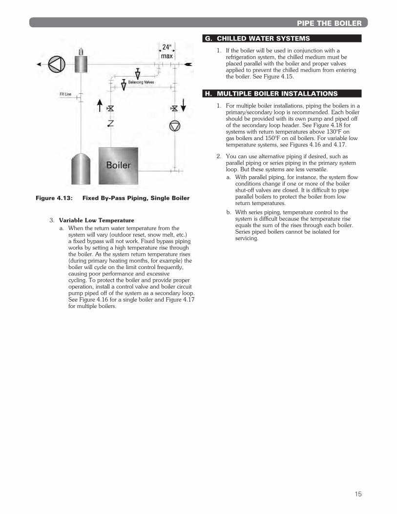
3. Variable Low Temperaturea. When the return water temperature from the
system will vary (outdoor reset, snow melt, etc.) a fixed bypass will not work. Fixed bypass piping works by setting a high temperature rise through the boiler. As the system return temperature rises (during primary heating months, for example) the boiler will cycle on the limit control frequently, causing poor performance and excessive cycling. To protect the boiler and provide proper operation, install a control valve and boiler circuit pump piped off of the system as a secondary loop. See Figure 4.16 for a single boiler and Figure 4.17 for multiple boilers.
G. CHILLED WATER SYSTEMS
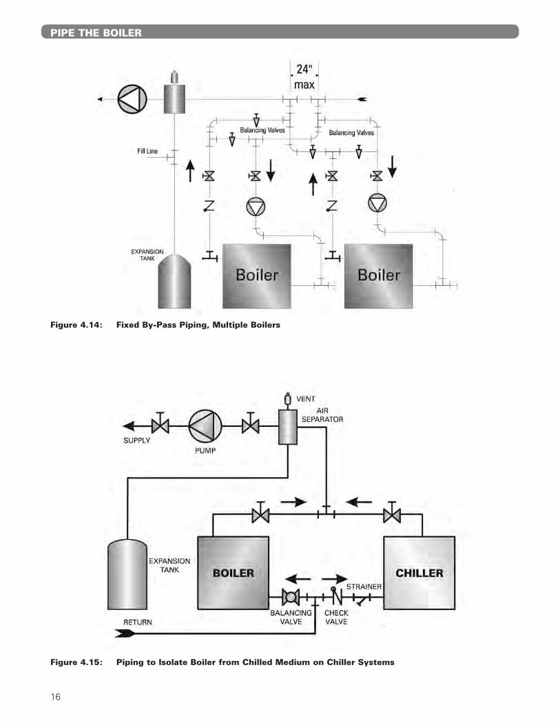
1. If the boiler will be used in conjunction with a refrigeration system, the chilled medium must be placed parallel with the boiler and proper valves applied to prevent the chilled medium from entering the boiler. See Figure 4.15.
H. MULTIPLE BOILER INSTALLATIONS
1. For multiple boiler installations, piping the boilers in a primary/secondary loop is recommended. Each boiler should be provided with its own pump and piped off of the secondary loop header. See Figure 4.18 for systems with return temperatures above 130°F on gas boilers and 150°F on oil boilers. For variable low temperature systems, see Figures 4.16 and 4.17.
2. You can use alternative piping if desired, such as parallel piping or series piping in the primary system loop. But these systems are less versatile.a. With parallel piping, for instance, the system flow
conditions change if one or more of the boiler shut-off valves are closed. It is difficult to pipe parallel boilers to protect the boiler from low return temperatures.
b. With series piping, temperature control to the system is difficult because the temperature rise equals the sum of the rises through each boiler. Series piped boilers cannot be isolated for servicing.
Figure 4.13: Fixed By-Pass Piping, Single Boiler
PIPE THE BOILER
16
Figure 4.14: Fixed By-Pass Piping, Multiple Boilers
PIPE THE BOILER
Figure 4.15: Piping to Isolate Boiler from Chilled Medium on Chiller Systems

17
PIPE THE BOILER
Figure 4.16: Piping for Variable Low Temperature Systems, Single Boiler

18
PIPE THE BOILER
Figure 4.17: Multiple Boiler Piping, System Return Temperature Below 130°F on Gas, 150°F on Oil

19
PIPE THE BOILER
Figure 4.18: Multiple Boiler Piping, System Return Temperature Above 130°F on Gas, 150°F on Oil

20
VENTING
5. VENTING A. GENERAL
Refer to Chapter 1, Preinstallation, Section D. Chimney and Breaching for installation requirements.
B. COMMON VENTING
At the time of removal of an existing boiler, follow these steps with each appliance remaining connected to the common venting system placed in operation, while the other appliances remaining connected to the common venting system are not in operation:
a. Seal any unused openings in the common venting system.
b. Visually inspect the venting system for proper size and horizontal pitch and determine there is no blockage or restriction, leakage, corrosion and other deficiencies which could cause an unsafe condition.
c. Insofar as is practical, close all building doors and windows and all doors between the space in which the appliances remaining connected to the common venting system are located and other spaces of the building. Turn on any clothes dryers and any appliance not connected to common venting system. Turn on any exhaust fans, such as range hoods and bathroom exhausts, so they will operate at maximum speed. Do not operate a summer exhaust fan. Close fireplace dampers.
d. Place in operation the appliance being inspected. Follow the lighting instructions. Adjust thermostat so appliance will operate continuously.
e. Test for spillage at the draft hood relief opening after 5 minutes of main burner operation. Use the flame of a match or candle, or smoke from a cigarette, cigar, or pipe.
f. After it has been determined that each appliance remaining connected to the common venting system properly vents when tested as outlined above, return doors, windows, exhaust fans, fireplace dampers and any other gas-burning appliance to their previous conditions of use.
g. Any improper operation of the common venting system should be corrected so that the installation conforms with the current edition of the National Fuel Gas Code, ANSI Z223.1/NFPA 54 and/or CAN/CSA B149.1, Natural Gas and Propane Installation Code. When resizing any portion of the common venting system, the common venting system should be resized to approach the minimum size as determined using the appropriate tables in the National Fuel Gas Code, ANSI Z223.1/NFPA 54 and/or CAN/CSA B149.1, Natural Gas and Propane Installation Code.

21
BURNER INSTALLATION
1. The burner is supplied with a mounting flange fixed in position.
2. Mount the burner to the combustion chamber cover plate (3) with four 5/16”-18 x 1” studs and nuts provided. BE SURE HI TEMP GASKET IS BETWEEN THE BURNER MOUNTING FLANGE AND THE COMBUSTION CHAMBER COVER PLATE.
3. Burner Specifications.
4. For other information pertinent to the burner installation, see the Installation Manual accompanying the burner.
BECKETT BURNERBoiler
Model No.Burner
Model No.*Nozzle
SizePressure
psigSC(T)-05 CF-500 2.50 60° B 140SC(T)-06 CF-500 3.00 60° B 140SC(T)-07 CF-800 3.25 45° B 150SC(T)-08 CF-800 3.75 45° B 140SC(T)-09 CF-800 4.00 30° B 150SC(T)-10 CF-800 4.50 30° B 150
CARLIN BURNERBoiler
Model No.Burner
Model No.*Nozzle
SizePressure
psigSC(T)-05 201 CRD 2.50 60° B 140SC(T)-06 201 CRD 3.00 60° B 140SC(T)-07 201 CRD 3.25 45° SS 150SC(T)-08 201 CRD 3.75 45° SS 140SC(T)-09 301 CRD 4.00 45° B 150SC(T)-10 301 CRD 4.50 45° B 150
POWER FLAME GAS OR COMB. GAS-OIL BURNERSBoiler
Model No.Gas Burner Model No.
Gas-Oil Model No.
*Nozzle Size
Pressure psig
SC(T)-05 CR1-G-10 CR1-GO-10 1.75 90° S 300SC(T)-06 CR1-G-10 CR1-GO-10 2.25 90° S 275SC(T)-07 CR1-G-10 CR1-GO-10 2.50 90° S 275SC(T)-08 CR1-G-10 CR1-GO-10 2.75 90° S 275SC(T)-09 CR1-G-10 CR1-GO-10 3.00 90° S 275SC(T)-10 CR1-G-10 CR1-GO-10 3.50 90° S 250
BECKETT GAS BURNERSBoiler
Model No.Burner
Model No.Standard Combustion
ControlSC(T)-05 CG10.1 RM7895ASC(T)-06 CG10.3 RM7895ASC(T)-07 CG10.3 RM7895ASC(T)-08 CG10.4S RM7895ASC(T)-09 CG10.4S RM7895ASC(T)-10 CG10.5S RM7895A
*Nozzle Size: B = Delavan P/SS = Hago S = Steinen
POWER FLAME GAS BURNERSBoiler
Model No.Burner
Model No.Side Orifice
Drill Size (inches)SC(T)-05 JR15A-10 3/8SC(T)-06 JR15A-10 7/16SC(T)-07 JR15A-10 15/32SC(T)-08 JR30A-10 1/2SC(T)-09 JR30A-10 17/32SC(T)-10 JR30A-10 19/32
6. INSTALL THE BURNER
MIDCO GAS BURNERS
Boiler Model No.
Burner Model No.1
Burner Model No.2
Natural Gas Side Orifice
Drill Size (inches)
LP Gas Side Orifice
Drill Size (inches)
SC(T)-05 RE6850 RE6850B 31/64 23/64SC(T)-06 RE6850 RE6850B 31/64 23/64SC(T)-07 RE6850 RE6850B 9/16 31/64SC(T)-08 RE6850 RE6850B None 9/16SC(T)-09 RE6850 RE6850B None 9/16SC(T)-10 RE6850 RE6850B None None
1. Honeywell RM7895A 120 VAC Control 2. Honeywell S8680J 24 VAC Control
INSTALL THE BURNER
22
CONNECT FUEL PIPING
7. CONNECT FUEL PIPING
A. GENERAL
1. Read the Burner Instruction Manual, supplied with the boiler or with the burner if purchased separately. Review applicable code requirements for burner and fuel piping installations.
2. Install piping to allow removal of burner and access to combustion chamber for cleaning or service.
B. INSTALL FUEL OIL PIPING
1. Place the fuel oil tank and install the piping in accordance with NFPA-31 and all other applicable codes. Refer to Burner Operation Manual for instructions regarding the connection of the fuel line to the Burner.
2. General Guidelines for Oil Pipinga) Follow the guidelines in the Burner Manual for
sizing oil lines.
b) Install manual shut-off valves on the suction line at the burner and at the oil line entrance to the building. If installing a shut-off valve on the return line, you must provide an oil pressure relief valve piped ahead of the shut-off valve and discharged to the tank to prevent over-pressure conditions.
c) Install a two-pipe oil distribution system when possible. It will improve the reliability of the oil delivery to the burner.
d) Use flare fittings when using copper tubing.
e) Provide an oil line filter in the suction line. Size the filter for the suction gear capacity of the burner oil pump if running a two-pipe system.
f) If burner is above the top of the fuel oil tank, install a check valve on the oil suction line at the burner to prevent oil from evacuating the line. If burner is below the top of the tank, install an anti-siphon device to prevent oil flow should the oil line break.
C. INSTALL GAS SUPPLY PIPING
1. Size the piping as required by the National Fuel Gas Code, ANSI Z223.1 or as required by local codes. Use Table 7.1 for sizing of natural gas for a system
pressure drop of 0.3 inch water column.
2. The standard gas train is designed for a maximum pressure of 1/2 psig (14 inches water column). Make sure the system regulator will not allow a higher pressure to the Gas Control Train under any conditions.
3. The minimum gas supply pressure is listed on the Burner Rating Plate. Make sure the system regulator and the piping are sized and adjusted properly to provide this pressure under all conditions.
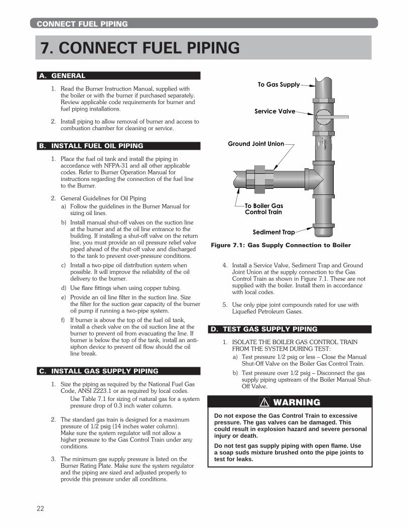
4. Install a Service Valve, Sediment Trap and Ground Joint Union at the supply connection to the Gas Control Train as shown in Figure 7.1. These are not supplied with the boiler. Install them in accordance with local codes.
5. Use only pipe joint compounds rated for use with Liquefied Petroleum Gases.
D. TEST GAS SUPPLY PIPING
1. ISOLATE THE BOILER GAS CONTROL TRAIN FROM THE SYSTEM DURING TEST:a) Test pressure 1/2 psig or less – Close the Manual
Shut-Off Valve on the Boiler Gas Control Train.
b) Test pressure over 1/2 psig – Disconnect the gas supply piping upstream of the Boiler Manual Shut-Off Valve.
To Gas Supply
Service Valve
Sediment Trap
Ground Joint Union
To Boiler GasControl Train
Figure 7.1: Gas Supply Connection to Boiler
Do not expose the Gas Control Train to excessive pressure. The gas valves can be damaged. This could result in explosion hazard and severe personal injury or death.
Do not test gas supply piping with open flame. Use a soap suds mixture brushed onto the pipe joints to test for leaks.
WARNING

23
Table 7.1: Capacity of Gas Supply Pipe in Cubic Feet Per Hour of Natural Gas for Pressure Drop of 0.3 inch Water Column.
Above ratings based on natural gas with specific gravity of 0.60 allowing pressure drop of 0.3 inches water column. No allowance is needed for pipe fittings. Use the following multipliers on above capacities for specific gravity other than 0.60:
CONNECT FUEL PIPING
Pipe Length (Feet)
1-1/4” Pipe
1-1/2” Pipe
2” Pipe
2-1/2” Pipe
3” Pipe
4” Pipe
6” Pipe
10 1050 1600 3050 4800 8500 17500 44000
20 730 1100 2100 3300 5900 12000 31000
30 590 890 1650 2700 4700 9700 25000
40 500 760 1450 2300 4100 8300 22000
50 440 670 1270 2000 3600 7400 20000
60 400 610 1150 1850 3250 6800 18000
70 350 560 1050 1700 3000 6200 17000
90 320 490 930 1500 2600 5400 15000
100 305 460 870 1400 5100 14000
150 250 380 710 1130 2000 4100 11500
Specific Gravity 0.50 0.55 0.60 0.65 0.70
Multiply Capacity by: 1.10 1.04 1.00 0.962 0.926

24
INSTALL CONTROLS & TRIM
8. INSTALL CONTROLS & TRIM A. CONTROLS
1. Apply controls as follows:a. Water Boilers: Install the limit or operating
control, temperature & pressure gauge and the pressure relief valve. See Figure 11.1 for proper location.
b. Steam Boilers: Install pressure gauge, gauge glass trim and safety valve. See Figures 8.1, 8.2 and 11.1. For application of low water cut-off see Figure 8.5. For pump control or feeder application see Figures 8.3 and 8.4.
B. CONTROL WIRING
1. All electrical wiring shall be done in accordance with the National Electrical Code and Local Requirements.
2. For recommended wiring, see Figure 8.6, Figure 8.7, and Burner Installation Manual.
3. For complete information on servicing and adjustment of controls, refer to the attached control specification sheets.
Pipe the discharge of the pop safety valve or relief valve to prevent injury in the event of pressure relief. Suggest discharge to be piped to drain. Pipe full size of outlet.
CAUTION
Figure 8.1: Steam Gauge/Pressuretrols Piping Arrangement
Single pole switches including those of safety controls or protective devices shall not be wired in a grounded line.
NOTICE

25
INSTALL CONTROLS & TRIM
Figure 8.2: Steam Gauge/Pressuretrols Alternate Piping Arrangement

26
Figure 8.3: McD&M 51 Low Water Cut-off and Feeder
INSTALL CONTROLS & TRIM

27
Figure 8.4: McD&M 157 Low Water Cut-off and Pump Control
Figure 8.5: McD&M #67PE-2 Low Water Cut-off
INSTALL CONTROLS & TRIM

28
Figure 8.6: Forced Hot Water with or without Tankless Water Heater
INSTALL CONTROLS & TRIM

29
Figure 8.7: Steam with or without Tankless Water Heater and Gravity Hot Water
INSTALL CONTROLS & TRIM
30
A. CHECK THE PIPING
1. Water/Steam Pipinga) The Boiler must have been hydrostatically tested.
b) Check the attached piping for joint tightness.
c) Continue monitoring as you proceed through start up.
2. Gas Pipinga) Make sure the gas system piping and the
connections to the boiler Gas Control Train(s) have been leak tested.
b) After the boiler is in operation, check the tightness of all joints in the boiler gas piping with a soap suds solution.
c) Purge the gas piping of all air up to the boiler Gas Control Train.
3. Oil Pipinga) Check the oil piping visually. Make sure all joints
are tight.
b) When the burner is firing, check the suction line and return line pressures.
c) If the pressure exceeds the allowable pressure in the Burner Manual or if the suction line vacuum is higher than allowable, correct the piping as needed to bring the suction line and return line pressures within acceptable range.
d) Excess pressure can cause pump seal failures. Excess vacuum will cause fuel flow problems with the burner oil pump.
B1. FILL THE BOILER (WATER BOILERS)
1. Fill the boiler and system with water making certain to vent air from all high points in the system. Water should bleed from each air vent when it is opened.
2. The pressure reducing valve on the fill line will typically allow the system to be filled and pressurized to 12 psi. Consult the valve and expansion tank manufacturer for more detailed information.
3. Check all joints and fittings throughout the system for leaks. If leaks are found, drain the system and repair as required.
4. If the water hardness is high, use water treatment to reduce the deposition of minerals in the boiler.
5. If the water pH is out of 7.5 to 11 range, add water treatment chemicals to bring within range, if required.
6. If the system requires antifreeze protection, use only propylene glycol specially formulated for hydronic systems. These contain inhibitors that prevent corrosion of the boiler and system components. Do not use ethylene glycol or automotive antifreezes.
a. Make sure that the antifreeze supplier can provide periodic testing of antifreeze concentration and inhibitor level.
b. If an automatic fill valve is used, the solution strength in the system must be checked to assure that the antifreeze concentration has not been overly diluted.
c. Local codes may require the addition of a backflow preventer or manual fill only with separation from the city water supply.
d. Consider the minimum temperature of potential exposure in the system when deciding on the antifreeze concentration. A concentration of 50% generally provides protection from freezing to -30°F.
B2. FILL THE BOILER (STEAM BOILERS)
1. Gravity Systems – Fill the boiler to the normal water line as shown in Figure11.1.
2. Pumped Return Systems with Condensate Unit - Fill the boiler using the boiler feed unit. Verify the unit maintains a water level that is visible in the gauge glass and does not exceed the normal water level shown in Figure 11.1.
3. Check all joints and fittings in the system piping for leaks and repair as necessary
4. If the water hardness is high, use water treatment to reduce the deposition of minerals in the boiler.
5 If the water pH is out of 7.5 to 11 range, add water treatment chemicals to bring within range, if required.
C. RUN BURNER CHECK-OUT
1. Before firing the burner, open the damper at the flue collector.
2. Follow the instructions in the Burner Manual for starting the burner, adjusting air openings and fuel rates. Perform ignition system and flame supervisory control test and checkout as described in the manual.
3. After the burner is set at rate, close the damper until the pressure reading at the test opening is between 0” and 0.1” wc positive.
9. STARTING THE BOILER
STARTING THE BOILER

31
4. Adjust the burner as needed for a CO2 reading of:a) Oil burners: CO2 approximately 12.5% or 1%
less than the level at which the smoke reading goes above a trace on the Bacharach scale.
b) Gas burners: 9% to 10% with CO less than 50 ppm.
5. Inspect all flue gas joints (sections, attachments, breeching and vent) for gas tightness. Remove the jacket panels in order to thoroughly inspect all rope seal joints between the sections.
D. CHECK BOILER CONTROLS
1. Limit and Operating Temperature Controlsa) Lower the setting of each control until the burner
shuts down.
2. Low Water Cutoffsa) Test probe type controls by using the Push-to-
Test Button.
b) Test float type controls.
3. Follow additional instructions in the Burner Manual for proving the burner component operation.
4. Check all controls to make sure they function correctly.
5. After all controls have been proven, set the Operating and High Limit Temperature Controls to the temperatures desired.
E. CLEAN THE BOILER (STEAM BOILERS ONLY)
1. Clean the boiler as described below no later than one week after the initial start-up. Cleaning will be more effective if the boiler operates a day or two to loosen sediment and impurities in the system.
2. Follow the cleaning instructions in section “G. Clean the Boilers” in the Maintenance Section of this manual.
3. The boiler must be cleaned to remove any accumulation of oil, grease, sludge, etc. that may be in the system. These substances can cause foaming and surging of the boiler water, producing unstable water line and water carryover to the system.
4. The piping for a 2” Skim Valve must be done as shown in this manual, with the skim valve mounted off the Pop Safety Valve tee on the rear of the boiler.
5. Use common washing soda (such as Arm and Hammer Super Washing Soda). Mix the soda with water in a 10 quart pail. Use a proportion of one pound of washing soda for each 800 square feet EDR net boiler rating. Remove the Pop Safety Valve and pour the washing soda solution into the boiler through the Pop Safety Valve tee. Replace Pop Safety Valve.
6. Connect a 2 inch drain line off of the Skim Valve, run to a point of safe discharge.
7. Close all valves to the system. Provide a means of continuous fresh water to the boiler for the cleaning process.
8. Open the Skim Valve. Fill the boiler until water begins to flow out of the valve.
9. Turn burner on and allow the boiler water to heat up to just below steaming (180° to 200° F). Cycle the burner to maintain temperature during skimming. Do not allow the boiler to steam. Steaming mixes up the contaminants in the water instead of floating them at the surface.
10. Open the make-up water valve to continuously feed water to the boiler. Allow water to flow out the skim tapping.
11. Continue skimming the boiler until the water flowing from the skim tapping flows clear. This will take some time, possibly several hours for a dirty system.
12. After skimming is complete, close the skim valve and turn off the boiler.
13. Close the make-up water valve and open the boiler blowdown valves.
14. Drain the boiler completely, then refill and drain again one or two times to make sure all of the soda has been washed out.
15. Restore piping to normal. Pipe a nipple and cap in the skim valve.
16. Note: If the gauge glass becomes dirty again, this indicates more contaminants have worked loose in the system. Repeat the cleaning and skimming process as needed to clean the system.
STARTING THE BOILER
On installations with high draft, do not leave the boiler with a negative draft reading at the draft damper. High negative draft can pull the flame up into the boiler crown sheet and overheat the iron. This can result in cracked sections or shortened boiler life.
CAUTION
Cleaning the boiler requires the use of very hot water and corrosive chemicals. Use care when handling to prevent injury.
WARNING
Do not leave the boiler unattended while firing.
Take great care not to allow the water level to drop below the bottom of the gauge glass or to allow fresh water make-up to flow in too fast. This will avoid the possibility of causing the boiler sections to fracture.
CAUTION
32
WARNING
Product Safety InformationRefractory Ceramic Fiber Product
This appliance contains materials made from refractory ceramic fibers (RCF). Airborne RCF, when inhaled, have been classified by the International Agency for Research on Cancer (IARC), as a possible carcinogen to humans. After the RCF materials have been exposed to temperatures above 1800°F (982°C), they can change into crystalline silica, which has been classified by the IARC as carcinogenic to humans. If particles become airborne during ser-vice or repair, inhalation of these particles may be hazardous to your health.
Avoid Breathing Fiber Particulates and Dust
Suppliers of RCF recommend the following precautions be taken when handling these materials:
Precautionary Measures:Provide adequate ventilation.Wear a NIOSH/MSHA approved respirator.Wear long sleeved, loose fitting clothing and gloves to prevent skin contact.Wear eye goggles.Minimize airborne dust prior to handling and removal by water misting the material and avoiding unnecessary disturbance of materials. Wash work clothes separately from others. Rinse washer thoroughly after use.Discard RCF materials by sealing in an airtight plastic bag.
First Aid Procedures:Inhalation: If breathing difficulty or irritation occurs, move to a location with fresh clean air. Seek immediate medical attention if symptoms persist.Skin Contact: Wash affected area gently with a mild soap and warm water. Seek immediate medical attention if irritation persists.Eye Contact: Flush eyes with water for 15 minutes while holding eyelids apart. Do not rub eyes. Seek immediate medical attention if irritation persists.Ingestion: Drink 1 to 2 glasses of water. Do not induce vomiting. Seek immediate medical attention.
MAINTENANCE
10. MAINTENANCE

33
A. PLACING BOILER IN OPERATION
1. Start up the Burner/Boiler per the Burner Manual and the instructions in this manual on starting the boiler.
2. Prove the correct operation of all controls on the boiler and burner as outlined below.
3. Check the operation of the ignition and flame proving controls as described in the Burner Manual.
4. Test the limit and operating controls to assure they are operating correctly.
5. Inspect and test all low water cutoffs.
6. Test the safety relief valve(s) using the procedure given by the valve manufacturer on the valve tag.
7. Visually inspect the burner and pilot flames (if applicable).
B. TO SHUT DOWN THE BOILER
1. Turn off Burner.
2. Open main line power disconnect switch to boiler/burner.
3. Close fuel shut-off valves.
4. To take boiler out of service if the boiler and system are not to be used when temperatures are below freezing:a) Drain the boiler and system completely and shut
off make-up water supply.
b) Open main line power disconnect switch to boiler/burner. Remove the fuses or secure the switch so that the power cannot be turned on accidentally.
c) Be certain that the boiler and system are refilled before returning to service. Follow the Instructions in this manual and the Lighting Instructions to operate.
d) The system may be filled with a 50% inhibited propylene glycol solution for protection down to -35°F. Use only antifreeze solutions specifically designed for hydronic use.
C. MAINTENANCE – ANNUAL
1. Before the start of each heating season, inspect and make all necessary adjustments to insure proper boiler and burner operation. Use the maintenance and inspection procedures following.
2. Inspect the Venting System
a) Check the chimney or vent to make sure it is clean and free from cracks or potential leaks.
b) All joints must be tight and sealed.
c) The vent connector must extend into, but not beyond the inside edge of the chimney or vent.
3. Inspect the Boiler Areaa) The boiler area must be clean and free from
combustible materials, gasoline or any other flammable liquids or vapors.
b) The combustion air openings and the area around the boiler must be unobstructed.
4. Inspect boiler flueways and burner for cleanliness. Follow the cleaning procedure in part F. of this chapter.
5. Inspect the boiler and piping for signs of leaks. Check to see if there are signs of heavy make-up water addition to the system. See Section 1 - Preinstallation for boiler water quality requirements.
6. When placing boiler into operation, follow Burner Manual, all instructions supplied with the boiler and the instructions in this chapter.
7. Test the operation of all limit controls, float controls and ignition components as described in Part A, “Placing Boiler in Operation”, of this chapter.
D. MONTHLY MAINTENANCE
1. Inspect the burner and pilot flames as for the annual inspection.
2. Inspect the boiler and system for any signs of leakage or excessive make-up water usage.
3. Inspect and check the operation of the venting system.
MAINTENANCE
Do not store or allow combustible or flammable materials near the boiler. Substantial fire or explosion hazard could result, causing risk of personal injury, death or property damage.
Do not use this boiler if any part of it has been under water. Immediately call a qualified service technician to inspect the boiler. Any part of the control system, any gas control or any burner or gas component which has been under water must be replaced.
Should overheating occur or the fuel supply fail to shut off: Shut off the fuel supply at a location external to the boiler. Do not turn off or disconnect the electrical supply to the pump. Immediately call a qualified service technician to inspect the boiler for damage and defective components.
WARNING
Before servicing the boiler:
• Turn off all electrical power to the boiler.
• Close the Gas Service Valve and Oil Shut-Off Valve.
• Allow the boiler to cool if it has been operating.
• Label all wires prior to disconnection when servicing controls. Wiring errors can cause improper and dangerous operation. Verify proper operation after servicing.
CAUTION

34
E. DAILY MAINTENANCE
1. Inspect the boiler area to make sure the area is free from combustible or flammable materials and that there are not obstructions to the flow of air to the boiler or combustion air openings to the room.
2. Check for water leaks in boiler and system piping. If boiler includes an automatic water feeder, see Section 1 - Preinstallation, Part D - Boiler Water Quality and Treatment.
F. CLEANING HEATING SURFACES
NOTE: BOILER IS TO BE CLEANED AT LEAST ONCE A YEAR. THIS BOILER MAY BE CLEANED FROM THE LEFT SIDE OR TOP.
1. Turn off all electrical power to boiler before beginning cleaning operation.
2. If cleaning from the side, remove left jacket panel and side clean-out cover plates.
3. If cleaning from the top, remove flue pipe, left top jacket panel and flue collector.
4. Brush the flue passages with a wire brush to remove all scale or soot from these heating surfaces.
5. Remove any scale or soot from the fire box by means of vacuum cleaning or any other available means.
NOTE: THE OIL BURNER MUST BE REMOVED TO FACILITATE THIS OPERATION.
6. Install clean-out covers or flue collector, be sure the gasket or rope seal is in good condition. If not, replace.
7. Install jacket panels and flue pipe as required.
G. CLEAN THE BOILER (STEAM BOILERS ONLY)
1. Clean the boiler within one week after initial start-up. Cleaning will be more effective if boiler operates a day or two to loosen sediment and impurities in system.
2. Boiler must be cleaned to remove any accumulation of oil, grease, sludge, etc. in the system. These substances can cause foaming and surging of boiler water, producing an unstable water line and water carryover to system.
3. Connect a skim valve off the 1-1/2 NPT skim tapping on rear of boiler. See Figure 11.1 for skim tapping location. Run a 1-1/2 NPT drain line off skim valve to a point of safe discharge.
4. Provide a means of supplying continuous fresh water to the boiler for the cleaning process.
5. Use common washing soda, such as Arm and Hammer Super Washing Soda. Mix 1/2 pound of soda with water in a 10 quart pail. Mix a proportion of one (1) pound of washing soda for each 800 square feet EDR net boiler rating. Pour the mixture into the boiler through the safety relief valve tapping.
6. Open the skim valve. Fill boiler until water begins to flow out of the valve.
7. Turn on burner. Allow boiler water to heat up to just below steaming (180 - 200°F). Do not allow boiler to steam; steaming mixes up contaminants instead of floating them at surface.
8. Open make-up water valve to continually feed water to boiler. Adjust flow to maintain water temperature at 180 - 200°F.
9. Continue skimming boiler until water flowing from skim tapping flows clear. This will take some time, possibly several hours for a dirty system.
10. Turn off burner, close make-up water valve.
11. Drain boiler completely. Refill and drain one or two times to wash out all washing soda.
12. Remove skim valve and piping. Pipe a nipple and cap in the skim valve
MAINTENANCE
If gauge glass becomes dirty more contaminants have worked loose in system. Repeat cleaning and skimming process as needed to clean system.
NOTICE
Be very careful when adding water to a hot boiler. Add very slowly or, if possible, allow the boiler to cool naturally before adding water.
If an excessive loss of water occurs, check for a leak in the piping and correct the problem. Excessive make-up water will cause corrosion and damage to the boiler.
CAUTION
Cleaning the boiler requires the use of very hot water and corrosive chemicals. Use care when handling to prevent injury.
WARNING
Do not leave boiler unattended while firing burner. Operating boiler with water below minimum permissible water level may fracture sections.
CAUTION
Do not allow make-up water to flow too fast. Excessive quantities of cold water may fracture sections.
CAUTION

35
Table 11.1: Boiler DimensionsSERIES SC™ DIMENSIONS (INCHES)
Boiler Model
Number
Number of
Sections
Jacket Depth “A”
Jacket Width “B”
Jacket Height
“C”
Rear of Jacket to c/l of Flue
“D”
Left of Jacket to c/l of Flue
“E”
Flue Size “F”
Approx. Dist. Between Tappings
“G”
Approx. Dist. Between Tappings
“G1”SC(T)-05 5 24-1/2” 22-1/2” 43-1/4” 13-1/4” 10” 7” 17-7/16” —
SC(T)-06 6 28-3/4” 22-1/2” 43-1/4” 15-3/8” 10” 9” 21-5/8” —
SC(T)-07 7 33” 22-1/2” 43-1/4” 17-1/2” 10” 9” 25-13/16” —
SC(T)-08 8 37-1/4” 22-1/2” 43-1/4” 19-5/8” 10” 9” 30” —
SC(T)-09 9 41-1/2” 22-1/2” 43-1/4” 21-3/4” 10” 10” 34-3/16” —
SC(T)-10 10 45-3/4” 22-1/2” 43-1/4” 23-7/8” 10” 10” 38-3/8” 17-1/8”
Note: Maximum burner length: Beckett = 13-1/2”, Power Flame C = 34”, Power Flame J = 24”, Webster JB-1 = 30”, Midco RE6850 = 21”.
11. BOILER DIMENSIONS & RATINGS
BOILER DIMENSIONS & RATINGS
Figure 11.1
Table 11.2: Boiler Ratings
The above ratings are based on 12.75% CO² (oil) and +.10 in. W.C. at the vent.
The Net Ratings shown include allowance for normal piping and pickup load in accordance with AHRI requirements. Water ratings are based on a piping and pickup allowance factor of 1.15. Steam ratings based on an allowance factor of 1.33. PB Heat should be consulted before selecting a boiler for gravity hot water installations and installations having unusual piping and pickup requirements such as extended piping systems, exposed piping, night set-back, etc. Ratings shown are for elevations up to 2,000 feet. For elevations above 2,000 feet ratings should be reduced at the rate of 4 percent for each 1,000 feet above sea level.
Oil Burner Input is based on G.P.H. with a heating value of 140,000 BTU/gal. Burner Input based on maximum altitude of 2,000 ft.—for other altitudes consult factory.
SERIES SC™ BOILER RATINGS
Series SC™
BoilerH.P.
WaterContent,
galBoilerModel
Number
Oil Input GasInput,MBH
GrossOutput,
MBH
Net Ratings Thermal Efficiency6
%
Combustion Efficiency
%GPH MBH Steam,
sqftWater, MBH
Steam, MBH Water Steam
Oil Gas Oil Gas
SC(T)-05 2.80 392 404 327 1,022 284 245 83.4 80.9 85.4 82.8 9.8 26.04 20.40
SC(T)-06 3.50 490 505 409 1,278 356 307 83.5 81.0 85.4 82.8 12.2 30.36 23.52
SC(T)-07 4.00 560 577 468 1,463 407 351 83.6 81.1 85.3 82.8 14.0 34.68 26.64
SC(T)-08 4.50 630 649 527 1,647 458 395 83.6 81.1 85.3 82.8 15.8 39.03 29.76
SC(T)-09 5.00 700 722 586 1,832 510 440 83.7 81.2 85.3 82.7 17.5 43.32 32.88
SC(T)-10 5.50 770 794 645 2,016 561 484 83.8 81.2 85.3 82.7 19.3 47.64 36.00

36
BOILER DIMENSIONS & RATINGS
Table 11.3: Boiler Tapping Locations
SERIES SC™ TAPPING LOCATIONS
Location Size N.P.T. Steam Water
H 3/4” Low Limit Control N/A
J 3/4”Pressure Gauge Operating Control & Limit Control
Operating Control
K 3/4” N/A Limit Control
L 1/4” N/A Theraltimeter
M 1/2”Gauge Glass &
Low Water Cut-offN/A
N 2” Return Optional Return
O 3/4”Secondary Probe
Low Water Cut-offSecondary Probe
Low Water Cut-off
P3/4” on 05-06 1” on 07-10
Safetly Valve Relief Valve
Q1-1/4” on 05-06 1-1/2” on 07-10
Return Return
R 3/4” Drain Cock Drain Cock
S 1-1/2” Skim Tapping Optional High Limit
T 3/4”Primary Probe
Low Water Cut-offN/A
V 1”Optional Float
Low Water Cut-offOptional Float
Low Water Cut-off

37
This page intentionally left blank.

38
1
2
26
23
4
3
5
11
13
12
14
22
8
9
2524
19
16
1718
15
217
6
20
10
Figure 12.1
REPAIR PARTS
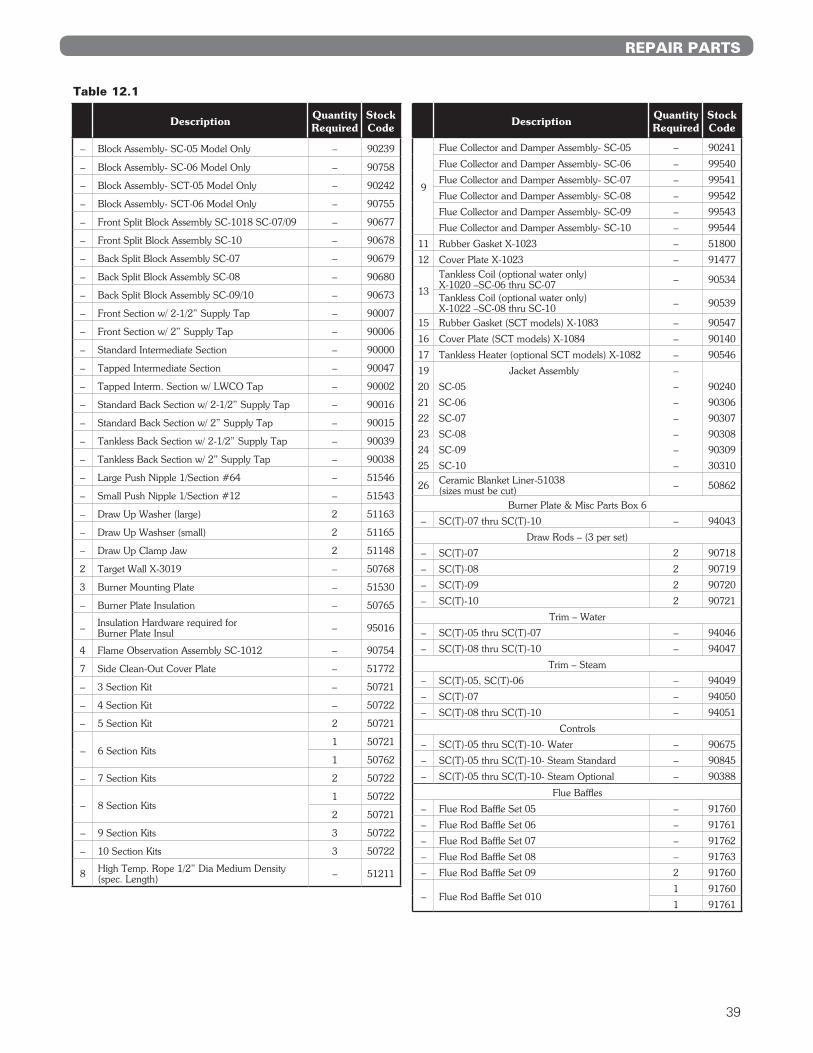
12. REPAIR PARTSRepair parts are available from your local PB Heat, LLC distributor or from Parts To YourDoor at 1 (610) 916-5380 (www.partstoyourdoor.com).
Note: Remember to include boiler model number and serial number when ordering parts.
39
Description Quantity Required
Stock Code
– Block Assembly- SC-05 Model Only – 90239
– Block Assembly- SC-06 Model Only – 90758
– Block Assembly- SCT-05 Model Only – 90242
– Block Assembly- SCT-06 Model Only – 90755
– Front Split Block Assembly SC-1018 SC-07/09 – 90677
– Front Split Block Assembly SC-10 – 90678
– Back Split Block Assembly SC-07 – 90679
– Back Split Block Assembly SC-08 – 90680
– Back Split Block Assembly SC-09/10 – 90673
– Front Section w/ 2-1/2” Supply Tap – 90007
– Front Section w/ 2” Supply Tap – 90006
– Standard Intermediate Section – 90000
– Tapped Intermediate Section – 90047
– Tapped Interm. Section w/ LWCO Tap – 90002
– Standard Back Section w/ 2-1/2” Supply Tap – 90016
– Standard Back Section w/ 2” Supply Tap – 90015
– Tankless Back Section w/ 2-1/2” Supply Tap – 90039
– Tankless Back Section w/ 2” Supply Tap – 90038
– Large Push Nipple 1/Section #64 – 51546
– Small Push Nipple 1/Section #12 – 51543
– Draw Up Washer (large) 2 51163
– Draw Up Washser (small) 2 51165
– Draw Up Clamp Jaw 2 51148
2 Target Wall X-3019 – 50768
3 Burner Mounting Plate – 51530
– Burner Plate Insulation – 50765
– Insulation Hardware required for Burner Plate Insul – 95016
4 Flame Observation Assembly SC-1012 – 90754
7 Side Clean-Out Cover Plate – 51772
– 3 Section Kit – 50721
– 4 Section Kit – 50722
– 5 Section Kit 2 50721
– 6 Section Kits1 50721
1 50762
– 7 Section Kits 2 50722
– 8 Section Kits1 50722
2 50721
– 9 Section Kits 3 50722
– 10 Section Kits 3 50722
8 High Temp. Rope 1/2” Dia Medium Density (spec. Length) – 51211
Description Quantity Required
Stock Code
9
Flue Collector and Damper Assembly- SC-05 – 90241
Flue Collector and Damper Assembly- SC-06 – 99540
Flue Collector and Damper Assembly- SC-07 – 99541
Flue Collector and Damper Assembly- SC-08 – 99542
Flue Collector and Damper Assembly- SC-09 – 99543
Flue Collector and Damper Assembly- SC-10 – 99544
11 Rubber Gasket X-1023 – 51800
12 Cover Plate X-1023 – 91477
13
Tankless Coil (optional water only) X-1020 –SC-06 thru SC-07 – 90534
Tankless Coil (optional water only) X-1022 –SC-08 thru SC-10 – 90539
15 Rubber Gasket (SCT models) X-1083 – 90547
16 Cover Plate (SCT models) X-1084 – 90140
17 Tankless Heater (optional SCT models) X-1082 – 90546
19 Jacket Assembly –
20 SC-05 – 90240
21 SC-06 – 90306
22 SC-07 – 90307
23 SC-08 – 90308
24 SC-09 – 90309
25 SC-10 – 30310
26 Ceramic Blanket Liner-51038 (sizes must be cut) – 50862
Burner Plate & Misc Parts Box 6
– SC(T)-07 thru SC(T)-10 – 94043
Draw Rods – (3 per set)
– SC(T)-07 2 90718
– SC(T)-08 2 90719
– SC(T)-09 2 90720
– SC(T)-10 2 90721
Trim – Water
– SC(T)-05 thru SC(T)-07 – 94046
– SC(T)-08 thru SC(T)-10 – 94047
Trim – Steam
– SC(T)-05, SC(T)-06 – 94049
– SC(T)-07 – 94050
– SC(T)-08 thru SC(T)-10 – 94051
Controls
– SC(T)-05 thru SC(T)-10- Water – 90675
– SC(T)-05 thru SC(T)-10- Steam Standard – 90845
– SC(T)-05 thru SC(T)-10- Steam Optional – 90388
Flue Baffles
– Flue Rod Baffle Set 05 – 91760
– Flue Rod Baffle Set 06 – 91761
– Flue Rod Baffle Set 07 – 91762
– Flue Rod Baffle Set 08 – 91763
– Flue Rod Baffle Set 09 2 91760
– Flue Rod Baffle Set 0101 91760
1 91761
Table 12.1
REPAIR PARTS

13. STARTUP & SERVICE REPORT
Date
Boiler Model No. Burner Operation
Burner Type Mfr. No.
Air Settings
Air Settings
Primary
Primary
Main
Main
Room
Room
%
%
Total
Total
Pilot
Pilot
Stack
Stack
Supply
Bypass
(In.)
(In.)
(Gross)
(Gross)
" w.c.
psig
Stack
Stack
Press .
Press .
Orifice
Supply
" w.c.
" w.c.
" w.c.
psig
CO
Smoke
%
No.
Flame Signal
Flame Signal
Temp. °F
Temp. °F
Gas Pressure
Oil Pressure
Combustion Test Results:
CO2
CO2
%
%
Input
Input
(cfh )
(gph)
GasType
Oil
Low Fire
Low Fire
High Fire
High Fire
Check of Safety Controls
Low Water Cutoff
Pilot Fa ilure
Main Flame Failure
High Gas Press .
Low Gas Press .
Setting
Setting
" w.c.
" w.c.
Limit Control Settings
High Limit
Oil Nozzle —
Operating Cont.
gph
Mod. Cont.
Angle Spray
Hi-Lo Cont.
Type Make
Copies of Repor t to:
Remarks:
Startup By: Accepted By:
Job
Ser ial No.
40

SC™
Gas/Oil Boilers
SeriesOil, Gas &
Installation,Operation & MaintenanceManualTO THE INSTALLER: This manual is the property of the owner and must
be affixed near the boiler for future reference.
TO THE OWNER: This boiler should be inspected annually by a
Qualified Service Agency.
SC8000 R17 (05/20-1C) Printed in U.S.A.©2020 PB Heat, LLC. All rights reserved.
PB HEAT, LLC131 S. CHURCH STREET • BALLY, PA 19503