diagnosis & repair manual water leaks - wkjeeps.com -...
TRANSCRIPT
Rev. A
Jeep Wrangler
Diagnosis & Repair Manual
Water Leaks
General Notes
i
1. This manual applies to all Jeep models: 2/4 door & Hard/Soft Top
2. Before testing the vehicle, perform a review of the top system. Make sure all the latches are engaged, none of the top seals are puckered or distorted, the door seals are installed correctly, the tops are not out of alignment, etc.
3. Each leak area can have multiple root causes, as noted in the diagnosis tree. It is
important to water test each repair before starting the next.
4. If a leak cannot be reproduced, it is due to the period of time the vehicle is under wet conditions. Some leaks may take hours before leaking.
5. If a leak cannot be reproduced, apply all the repairs to the applicable areas as noted in
the diagnosis road map.
6. When the door is open, there is water run off from the roof that can soak the carpet. Be sure to explain to the customer that this cannot be fixed. This is an unfortunate condition with this type of vehicle, similar to convertibles.
7. It is important to understand where the leak ENDS up when diagnosing the vehicle.
Where the leak ends up, does not always explain where the leak originates. Refer to the diagnosis tree when determining which repairs to perform.
8. This repair procedure does NOT cover every possible water leak on the Jeep Wrangler.
The issues identified in this document are the major leaks that show up in the field.
9. Generally, a car wash is the preferred method to diagnose a vehicle.
10. If a hose is required, place on the top of the vehicle facing forward making sure water is getting to all areas. Do NOT directly spray in the area of question. This can create a “false” leak that cannot be fixed.
11. This manual is not intended to be a service manual. The content identifies the major
areas of water leaks, the critical characteristics of each area and how to repair them.
READ FIRST READ FIRST

Diagnosis Road Map
ii
JK Hard/Soft Top
Water is on center of Instrument Panel / Shifter
Freedom Top (Pages 6-11)
Water is on door trim panel or Instrument Panel at A-pillar
Windshield Header Seal
(Pages 1-2)
Door Fit (Page 3)
A-Pillar Mucket/Foam (Pages 4-5)
Water at Rear Hard Top Panel / B-pillar
Water is on front carpet
Rear Wheel Flare Holes
(Pages 17-18)
Cowl Side Panel (Pages 19-20)
Hard Top Seal (Pages 12-14)
Area of leaks
Repair Procedures
B-Pillar Mucket/Foam (Pages 15-16)
Door Primary Seal
Table of Contents
iii
I. Diagnosis Road Map i
II. General Notes ii
III. Water leak on Door Trim or Instrument Panel
a) Repair procedure for Windshield Header Seal 1-2
b) Repair procedure for Door Fits 3
c) Repair procedure for A-pillar mucket/foam 4-5
IV. Water leak on Instrument Panel/Console Center
a) Repair procedure for Freedom Panel Seal 6-11
b) Repair procedure for Freedom Panel latches 11
V. Water leak at B-plr
a) Repair procedure for Hard Top Seal 12-14
b) Repair procedure for B-pillar Mucket 15-16
VI. Water leak on front carpet
a) Repair procedure for rear wheel flare hole 17-18
b) Repair procedure for cowl side leaks 19-20
VII. Appendix
a) Foam Kit 21
b) Replacement part numbers 22
Windshield Header Seal Repair Procedure
Labor Op. Code: 235135 1
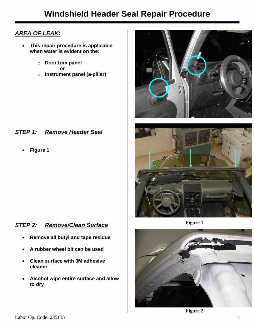
AREA OF LEAK:
• This repair procedure is applicable when water is evident on the:
o Door trim panel
or o Instrument panel (a-pillar)
STEP 1: Remove Header Seal
• Figure 1 STEP 2: Remove/Clean Surface
• Remove all butyl and tape residue
• A rubber wheel bit can be used
• Clean surface with 3M adhesive cleaner
• Alcohol wipe entire surface and allow
to dry
Figure 1
Figure 2
Windshield Header Seal Repair Procedure
Labor Op. Code: 235135 2
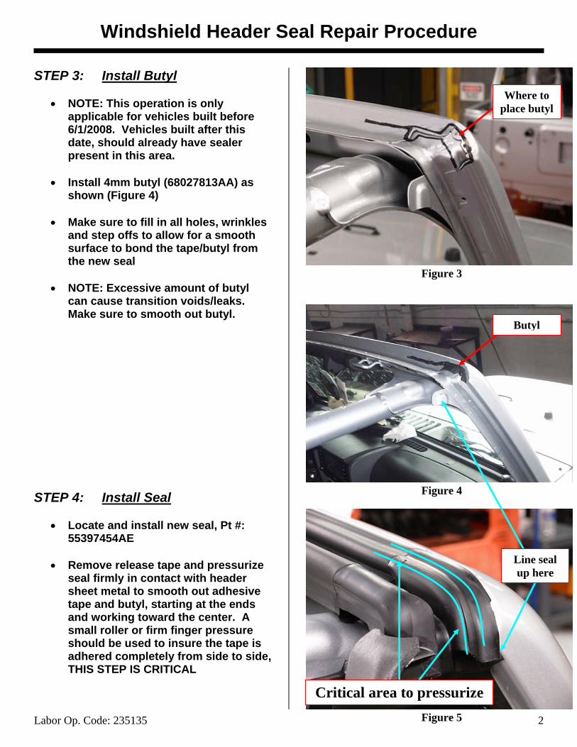
STEP 3: Install Butyl
• NOTE: This operation is only applicable for vehicles built before 6/1/2008. Vehicles built after this date, should already have sealer present in this area.
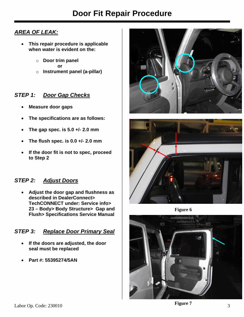
• Install 4mm butyl (68027813AA) as
shown (Figure 4)
• Make sure to fill in all holes, wrinkles and step offs to allow for a smooth surface to bond the tape/butyl from the new seal
• NOTE: Excessive amount of butyl
can cause transition voids/leaks. Make sure to smooth out butyl.
STEP 4: Install Seal
• Locate and install new seal, Pt #: 55397454AE
• Remove release tape and pressurize
seal firmly in contact with header sheet metal to smooth out adhesive tape and butyl, starting at the ends and working toward the center. A small roller or firm finger pressure should be used to insure the tape is adhered completely from side to side, THIS STEP IS CRITICAL
Line seal up here
Butyl
Where to place butyl
Critical area to pressurize
Figure 3
Figure 4
Figure 5
Door Fit Repair Procedure
Labor Op. Code: 230010 3
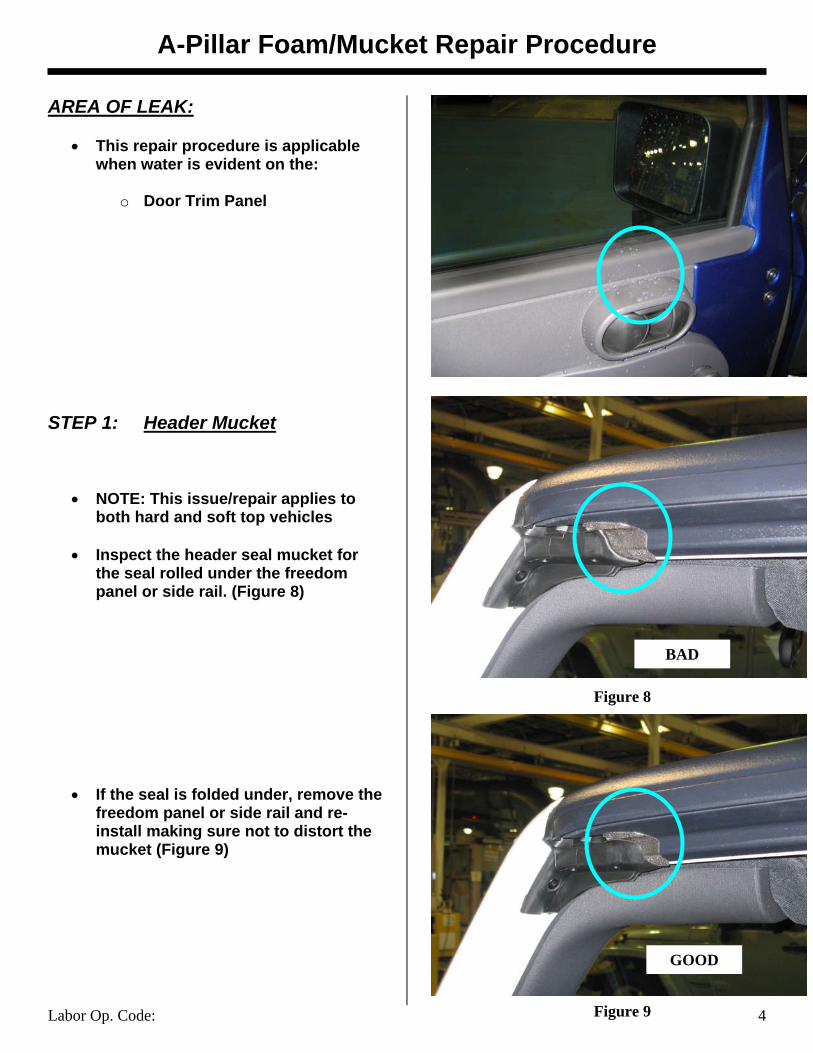
AREA OF LEAK:
• This repair procedure is applicable when water is evident on the:
o Door trim panel
or o Instrument panel (a-pillar)
STEP 1: Door Gap Checks
• Measure door gaps
• The specifications are as follows:
• The gap spec. is 5.0 +/- 2.0 mm
• The flush spec. is 0.0 +/- 2.0 mm
• If the door fit is not to spec, proceed to Step 2
STEP 2: Adjust Doors
• Adjust the door gap and flushness as described in DealerConnect> TechCONNECT under: Service info> 23 – Body> Body Structure> Gap and Flush> Specifications Service Manual
STEP 3: Replace Door Primary Seal
• If the doors are adjusted, the door seal must be replaced
• Part #: 55395274/5AN
Figure 6
Figure 7
A-Pillar Foam/Mucket Repair Procedure
Labor Op. Code: 4
AREA OF LEAK:
• This repair procedure is applicable when water is evident on the:
o Door Trim Panel
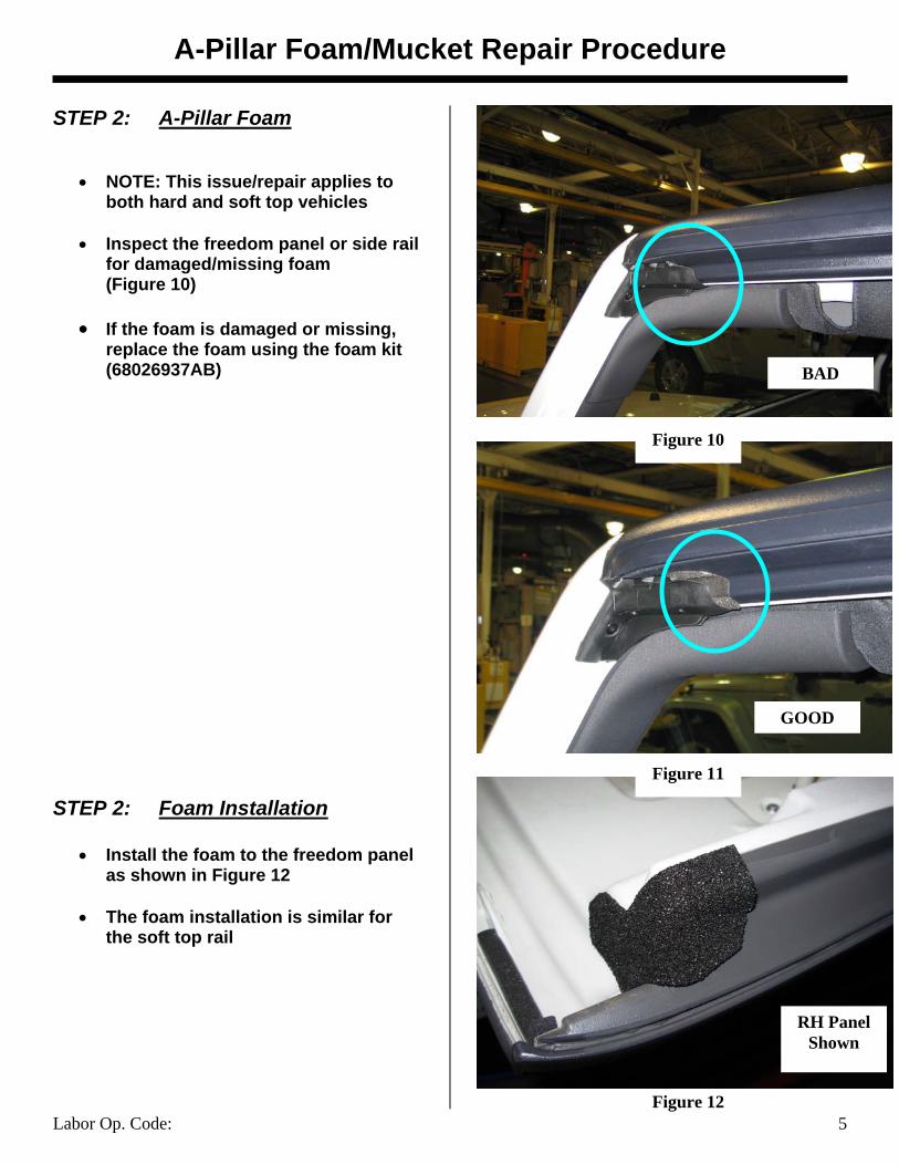
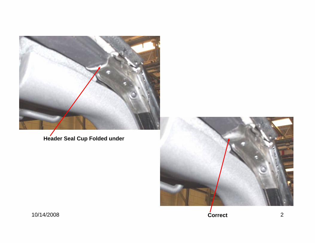
STEP 1: Header Mucket
• NOTE: This issue/repair applies to both hard and soft top vehicles
• Inspect the header seal mucket for
the seal rolled under the freedom panel or side rail. (Figure 8)
• If the seal is folded under, remove the freedom panel or side rail and re-install making sure not to distort the mucket (Figure 9)
BAD
GOOD
Figure 8
Figure 9
A-Pillar Foam/Mucket Repair Procedure
Labor Op. Code: 5
STEP 2: A-Pillar Foam
• NOTE: This issue/repair applies to both hard and soft top vehicles
• Inspect the freedom panel or side rail
for damaged/missing foam (Figure 10)
• If the foam is damaged or missing,
replace the foam using the foam kit (68026937AB)
STEP 2: Foam Installation
• Install the foam to the freedom panel as shown in Figure 12
• The foam installation is similar for
the soft top rail
Figure 10
Figure 11
Figure 12
RH Panel Shown
BAD
GOOD

B-Pillar Mucket/Foam Seal Repair
Labor Op. Code: 6
AREA OF LEAK:
• This repair procedure is applicable when water is evident on the:
o Instrument panel (Center)
or o Console / Shifter
RIGHT HAND FREEDOM PANEL STEP 1: Seal Removal
• Remove seal on Right panel
STEP 2: Tape and Butyl Removal
• Remove tape and butyl residue from panel
• A rubber wheel bit can be used
• Clean Seal Surface with: 3M General
Purpose Adhesive Cleaner or Kent Products Acrysol, (if available) and allow to dry completely
• Wipe seal surface with alcohol and
allow to dry completely.
Figure 13
Figure 14
Figure 15
B-Pillar Mucket/Foam Seal Repair
Labor Op. Code: 7
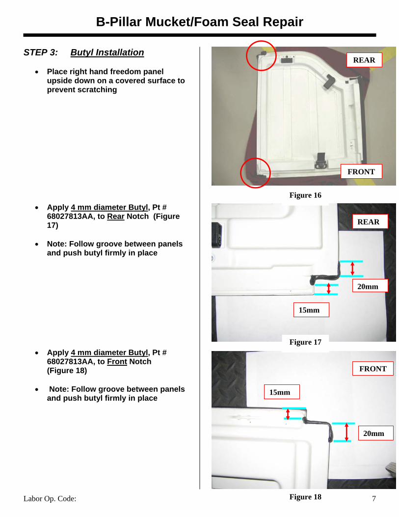
STEP 3: Butyl Installation
• Place right hand freedom panel upside down on a covered surface to prevent scratching
• Apply 4 mm diameter Butyl, Pt # 68027813AA, to Rear Notch (Figure 17)
• Note: Follow groove between panels
and push butyl firmly in place
• Apply 4 mm diameter Butyl, Pt # 68027813AA, to Front Notch (Figure 18)
• Note: Follow groove between panels
and push butyl firmly in place
REAR
REAR
FRONT
20mm
15mm
15mm
20mm
FRONT
Figure 18
Figure 16
Figure 17
B-Pillar Mucket/Foam Seal Repair
Labor Op. Code: 8
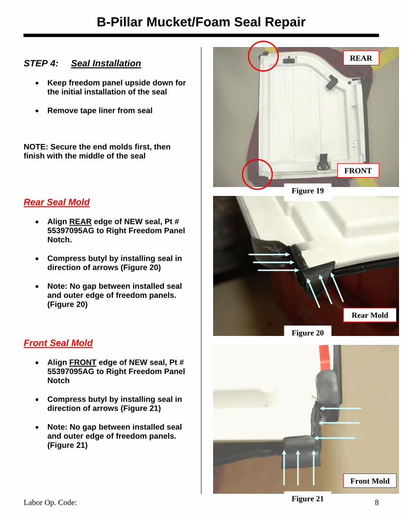
STEP 4: Seal Installation
• Keep freedom panel upside down for the initial installation of the seal
• Remove tape liner from seal
NOTE: Secure the end molds first, then finish with the middle of the seal Rear Seal Mold
• Align REAR edge of NEW seal, Pt # 55397095AG to Right Freedom Panel Notch.
• Compress butyl by installing seal in
direction of arrows (Figure 20)
• Note: No gap between installed seal and outer edge of freedom panels. (Figure 20)
Front Seal Mold
• Align FRONT edge of NEW seal, Pt # 55397095AG to Right Freedom Panel Notch
• Compress butyl by installing seal in
direction of arrows (Figure 21)
• Note: No gap between installed seal and outer edge of freedom panels. (Figure 21)
Rear Mold
Front Mold
REAR
FRONT
Figure 19
Figure 20
Figure 21
B-Pillar Mucket/Foam Seal Repair
Labor Op. Code: 9
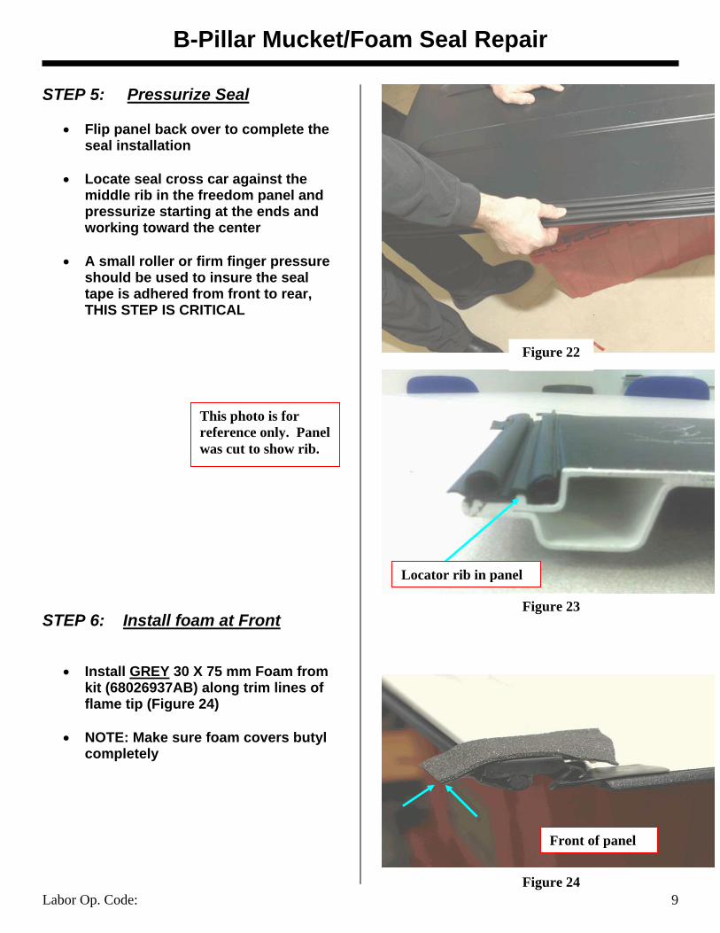
STEP 5: Pressurize Seal
• Flip panel back over to complete the seal installation
• Locate seal cross car against the
middle rib in the freedom panel and pressurize starting at the ends and working toward the center
• A small roller or firm finger pressure
should be used to insure the seal tape is adhered from front to rear, THIS STEP IS CRITICAL
STEP 6: Install foam at Front
• Install GREY 30 X 75 mm Foam from kit (68026937AB) along trim lines of flame tip (Figure 24)
• NOTE: Make sure foam covers butyl
completely
Front of panel
Locator rib in panel
Figure 22
Figure 23
Figure 24
This photo is for reference only. Panel was cut to show rib.
B-Pillar Mucket/Foam Seal Repair
Labor Op. Code: 10
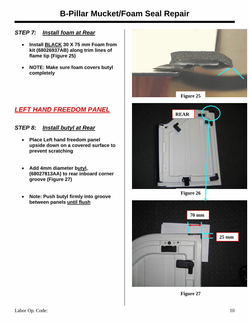
STEP 7: Install foam at Rear
• Install BLACK 30 X 75 mm Foam from kit (68026937AB) along trim lines of flame tip (Figure 25)
• NOTE: Make sure foam covers butyl
completely LEFT HAND FREEDOM PANEL STEP 8: Install butyl at Rear
• Place Left hand freedom panel upside down on a covered surface to prevent scratching
• Add 4mm diameter butyl, (68027813AA) to rear inboard corner groove (Figure 27)
• Note: Push butyl firmly into groove between panels until flush
Figure 26
REAR
70 mm
25 mm
Figure 25
Figure 27

B-Pillar Mucket/Foam Seal Repair
Labor Op. Code: 11
STEP 9: Install foam at Rear
• Add 30 X 75 mm Black Foam from Kit (68026937AB) to cover butyl
(Figure 28)
• NOTE: Make sure foam covers butyl completely
STEP 10: Install front latches • NOTE: This applies to both Right and
Left panels • If the vehicle MDH is prior to 12/07/07,
replace the front latches with part number 68004562AB (Figure 29)
Figure 28
Figure 29
B-Pillar Mucket/Foam Seal Repair
Labor Op. Code: 12
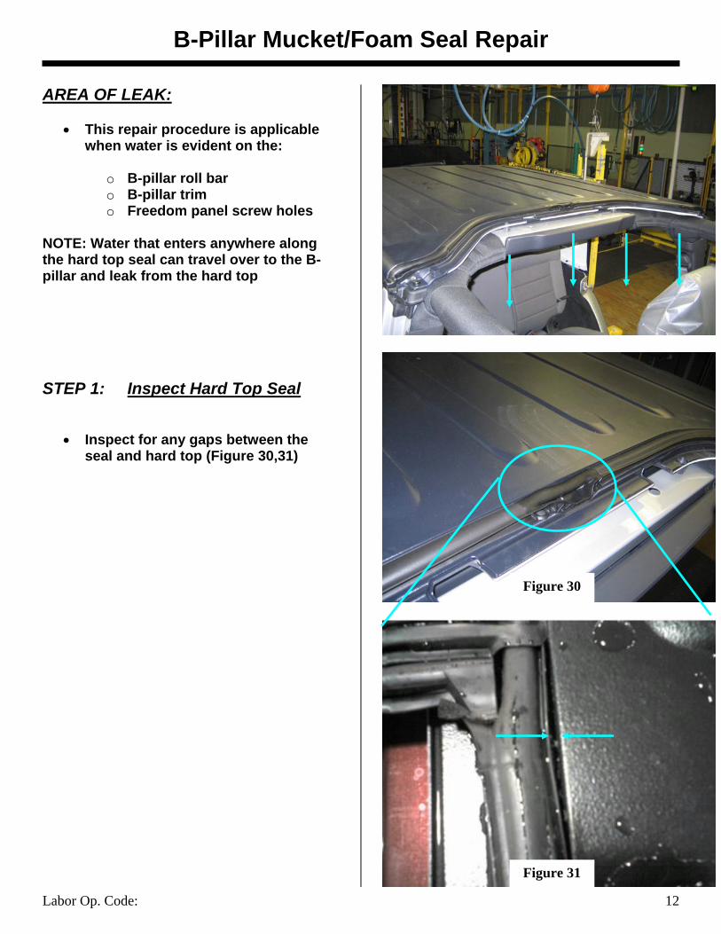
AREA OF LEAK:
• This repair procedure is applicable when water is evident on the:
o B-pillar roll bar o B-pillar trim o Freedom panel screw holes
NOTE: Water that enters anywhere along the hard top seal can travel over to the B-pillar and leak from the hard top STEP 1: Inspect Hard Top Seal
• Inspect for any gaps between the seal and hard top (Figure 30,31)
Figure 30
Figure 31
B-Pillar Mucket/Foam Seal Repair
Labor Op. Code: 13
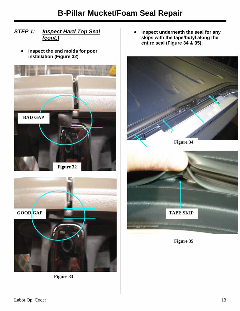
STEP 1: Inspect Hard Top Seal (cont.)
• Inspect the end molds for poor
installation (Figure 32)
• Inspect underneath the seal for any skips with the tape/butyl along the entire seal (Figure 34 & 35).
Figure 34
Figure 35
BAD GAP
GOOD GAP
Figure 32
Figure 33
TAPE SKIP
B-Pillar Mucket/Foam Seal Repair
Labor Op. Code: 14
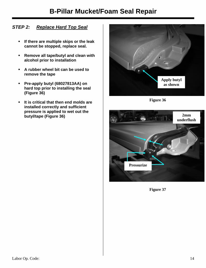
STEP 2: Replace Hard Top Seal
If there are multiple skips or the leak cannot be stopped, replace seal.
Remove all tape/butyl and clean with
alcohol prior to installation
A rubber wheel bit can be used to remove the tape
Pre-apply butyl (68027813AA) on
hard top prior to installing the seal (Figure 36)
It is critical that then end molds are
installed correctly and sufficient pressure is applied to wet out the butyl/tape (Figure 36)
2mm underflush
Figure 37
Figure 36
Apply butyl as shown
Pressurize
B-Pillar Mucket/Foam Seal Repair
Labor Op. Code: 15
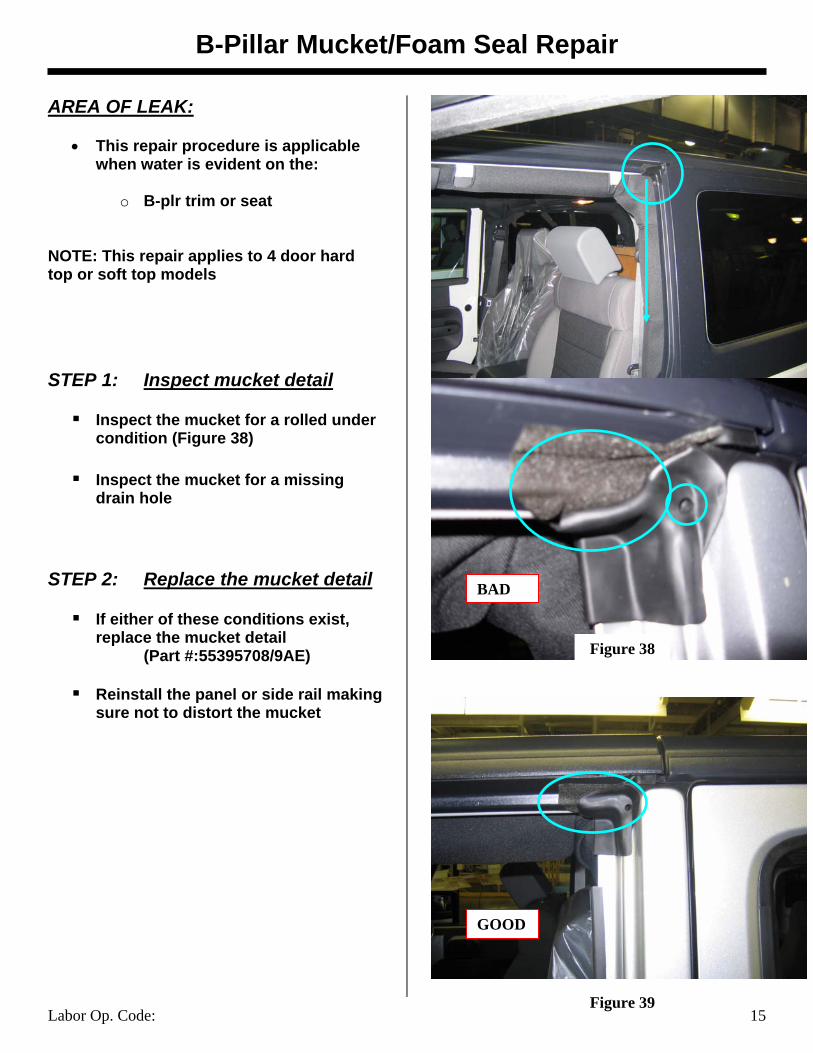
AREA OF LEAK:
• This repair procedure is applicable when water is evident on the:
o B-plr trim or seat
NOTE: This repair applies to 4 door hard top or soft top models STEP 1: Inspect mucket detail
Inspect the mucket for a rolled under condition (Figure 38)
Inspect the mucket for a missing
drain hole STEP 2: Replace the mucket detail
If either of these conditions exist, replace the mucket detail (Part #:55395708/9AE)
Reinstall the panel or side rail making
sure not to distort the mucket
GOOD
Figure 38
Figure 39
BAD
B-Pillar Mucket/Foam Seal Repair
Labor Op. Code: 16
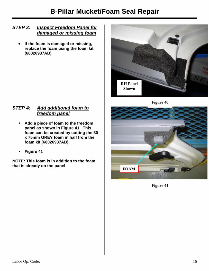
STEP 3: Inspect Freedom Panel for damaged or missing foam
• If the foam is damaged or missing,
replace the foam using the foam kit (68026937AB)
STEP 4: Add additional foam to
freedom panel
Add a piece of foam to the freedom panel as shown in Figure 41. This foam can be created by cutting the 30 x 75mm GREY foam in half from the foam kit (68026937AB)
Figure 41
NOTE: This foam is in addition to the foam that is already on the panel
FOAM
Figure 40
RH Panel Shown
Figure 41
Rear Wheel Flare Hole Repair
Labor Op. Code: 17
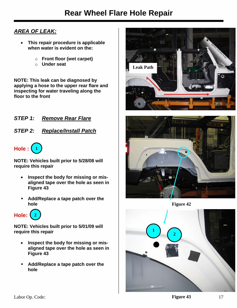
AREA OF LEAK:
• This repair procedure is applicable when water is evident on the:
o Front floor (wet carpet) o Under seat
NOTE: This leak can be diagnosed by applying a hose to the upper rear flare and inspecting for water traveling along the floor to the front STEP 1: Remove Rear Flare STEP 2: Replace/Install Patch Hole : NOTE: Vehicles built prior to 5/28/08 will require this repair
• Inspect the body for missing or mis-aligned tape over the hole as seen in Figure 43
Add/Replace a tape patch over the
hole Hole: NOTE: Vehicles built prior to 5/01/09 will require this repair
• Inspect the body for missing or mis-aligned tape over the hole as seen in Figure 43
Add/Replace a tape patch over the
hole
12
Figure 42
Figure 43
Leak Path
1
2
Rear Wheel Flare Hole Repair
Labor Op. Code: 18
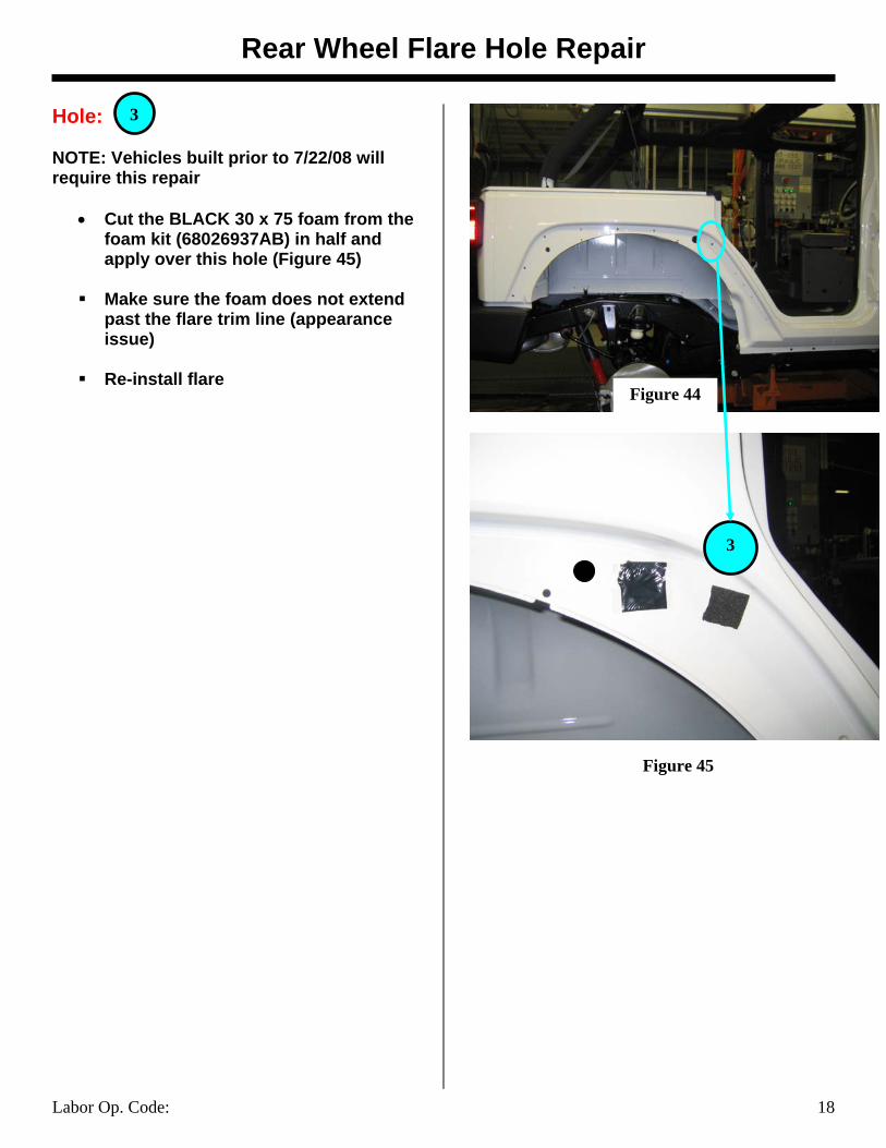
Hole: NOTE: Vehicles built prior to 7/22/08 will require this repair
• Cut the BLACK 30 x 75 foam from the foam kit (68026937AB) in half and apply over this hole (Figure 45)
Make sure the foam does not extend
past the flare trim line (appearance issue)
Re-install flare
3
Figure 45
Figure 44
3
Cowl Side Panel Repair
Labor Op. Code: 235001 19
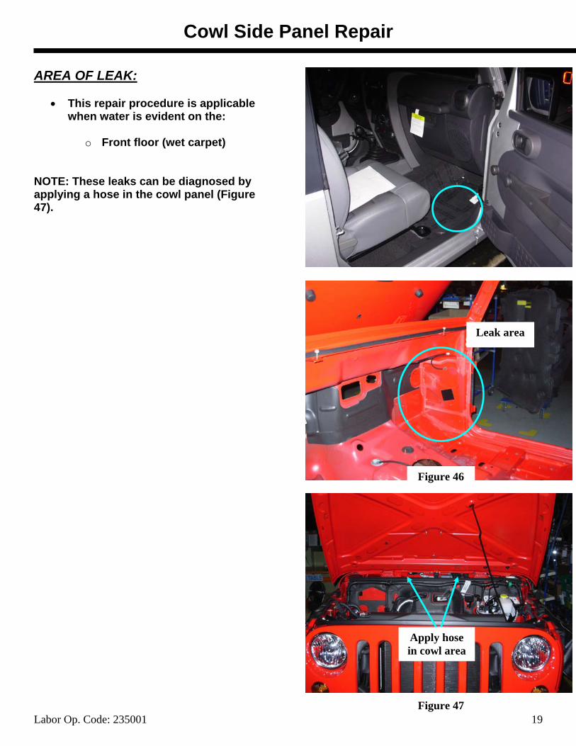
AREA OF LEAK:
• This repair procedure is applicable when water is evident on the:
o Front floor (wet carpet)
NOTE: These leaks can be diagnosed by applying a hose in the cowl panel (Figure 47).
Figure 46
Figure 47
Apply hose in cowl area
Leak area
Cowl Side Panel Repair
Labor Op. Code: 235001 20
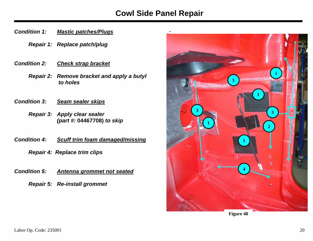
Condition 1: Mastic patches/Plugs
Repair 1: Replace patch/plug Condition 2: Check strap bracket
Repair 2: Remove bracket and apply a butyl to holes Condition 3: Seam sealer skips
Repair 3: Apply clear sealer (part #: 04467708) to skip
Condition 4: Scuff trim foam damaged/missing
Repair 4: Replace trim clips Condition 5: Antenna grommet not seated
Repair 5: Re-install grommet
_-
1
1
1
15
33
4
2
Figure 48
Appendix
Labor Op. Code: 21
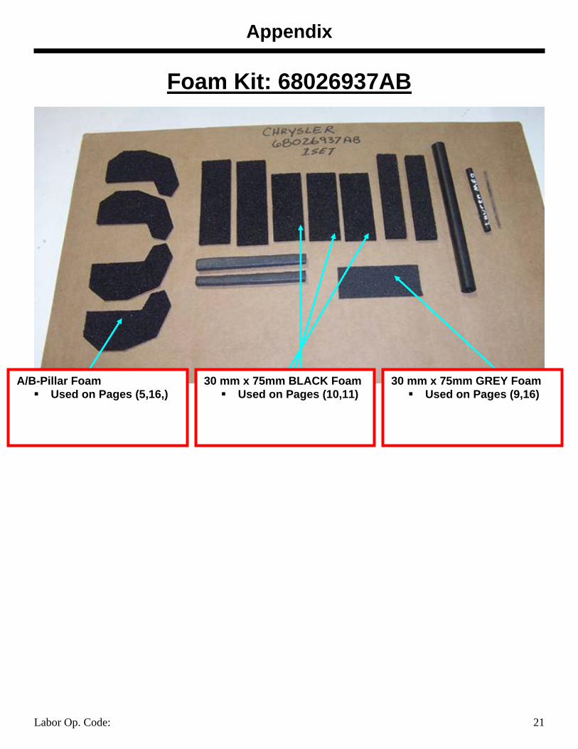
Foam Kit: 68026937AB
A/B-Pillar Foam Used on Pages (5,16,)
30 mm x 75mm BLACK Foam Used on Pages (10,11)
30 mm x 75mm GREY Foam Used on Pages (9,16)
Appendix
Labor Op. Code: 22
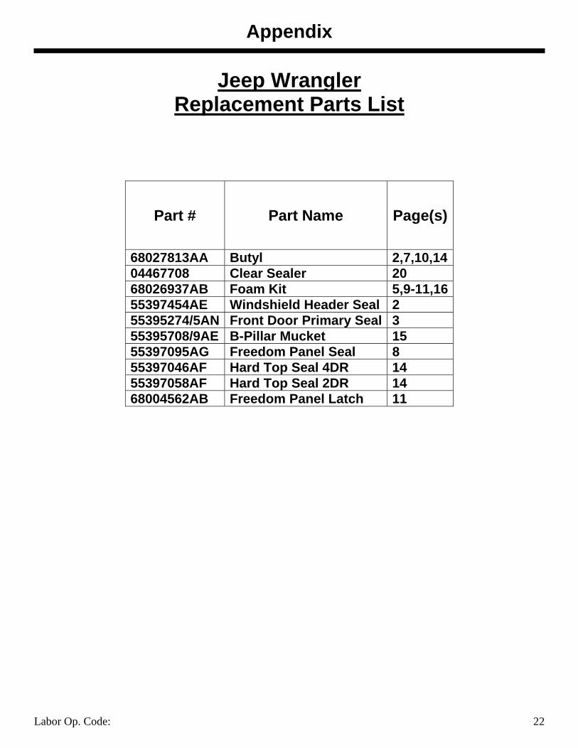
Jeep Wrangler Replacement Parts List
Part # Part Name Page(s)
68027813AA Butyl 2,7,10,14 04467708 Clear Sealer 20 68026937AB Foam Kit 5,9-11,16 55397454AE Windshield Header Seal 2 55395274/5AN Front Door Primary Seal 3 55395708/9AE B-Pillar Mucket 15 55397095AG Freedom Panel Seal 8 55397046AF Hard Top Seal 4DR 14 55397058AF Hard Top Seal 2DR 14 68004562AB Freedom Panel Latch 11
10/14/2008 1
JK Freedom Top-Center Front-
Water Leak RepairReference TSB # 23-020-08 As Required for additional Repair Information
10/14/2008 2
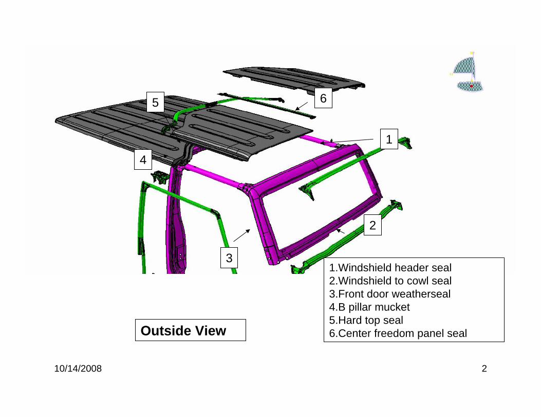
1
2
3
4
5 6
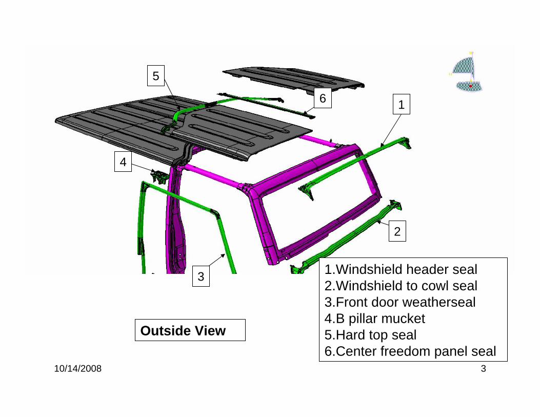
1.Windshield header seal2.Windshield to cowl seal3.Front door weatherseal4.B pillar mucket5.Hard top seal6.Center freedom panel sealOutside View
10/14/2008 3
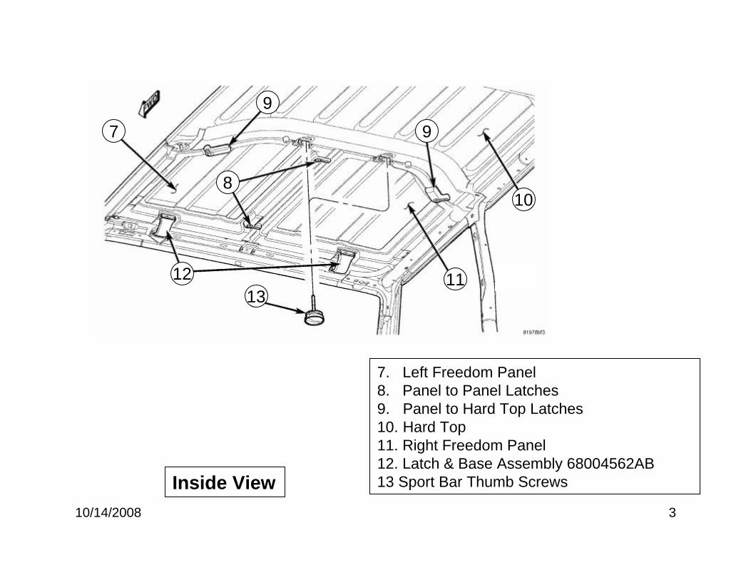
7
9
9
10
1112
8
13
Inside View
7. Left Freedom Panel8. Panel to Panel Latches9. Panel to Hard Top Latches10. Hard Top11. Right Freedom Panel12. Latch & Base Assembly 68004562AB13 Sport Bar Thumb Screws
10/14/2008 4
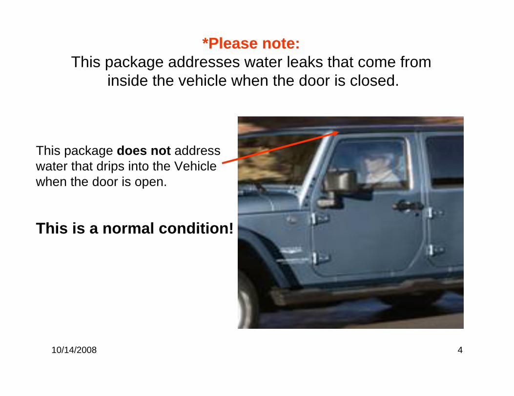
This package does not address water that drips into the Vehicle when the door is open.
This is a normal condition!
*Please note: This package addresses water leaks that come from
inside the vehicle when the door is closed.
10/14/2008 5
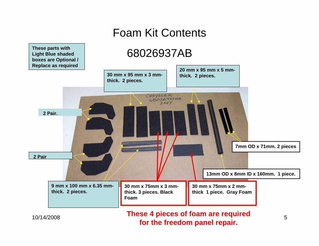
30 mm x 75mm x 3 mm-thick. 3 pieces. Black Foam
9 mm x 100 mm x 6.35 mm-thick. 2 pieces.
30 mm x 95 mm x 3 mm-thick. 2 pieces.
2 Pair
2 Pair.
20 mm x 95 mm x 5 mm-thick. 2 pieces.
7mm OD x 71mm. 2 pieces
13mm OD x 8mm ID x 160mm. 1 piece.
30 mm x 75mm x 2 mm-thick 1 piece. Gray Foam
Foam Kit Contents
68026937ABThese parts with Light Blue shaded boxes are Optional / Replace as required
These 4 pieces of foam are required for the freedom panel repair.
10/14/2008 6
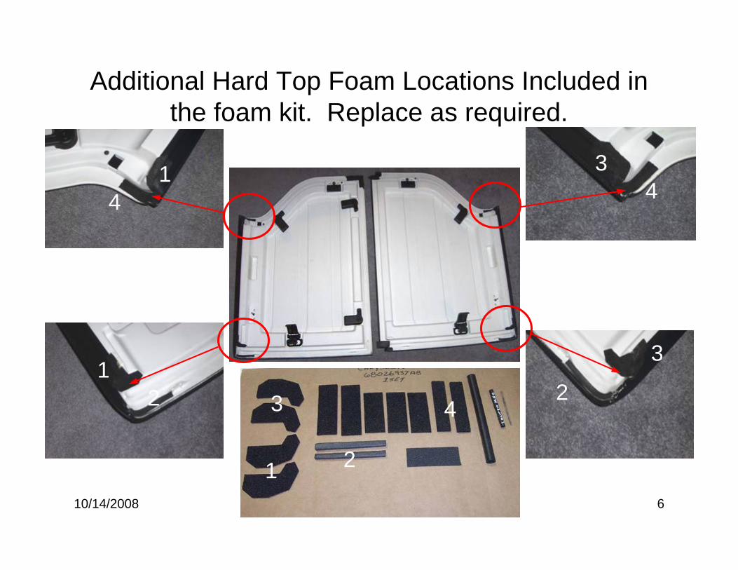
Additional Hard Top Foam Locations Included in the foam kit. Replace as required.
1
1
1
2
2 243
4 4
3
3
10/14/2008 7
Right Freedom Panel
Weather Strip Removal & Freedom panel Cleaning
10/14/2008 8
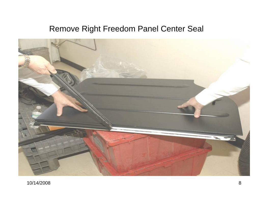
Remove Right Freedom Panel Center Seal
10/14/2008 9
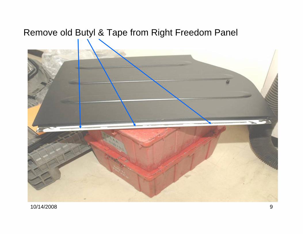
Remove old Butyl & Tape from Right Freedom Panel
10/14/2008 10
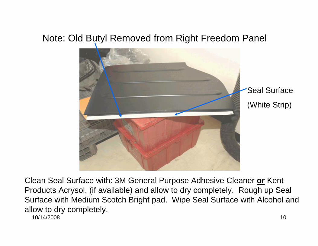
Note: Old Butyl Removed from Right Freedom Panel
Clean Seal Surface with: 3M General Purpose Adhesive Cleaner or Kent Products Acrysol, (if available) and allow to dry completely. Rough up Seal Surface with Medium Scotch Bright pad. Wipe Seal Surface with Alcohol and allow to dry completely.
Seal Surface
(White Strip)
10/14/2008 11
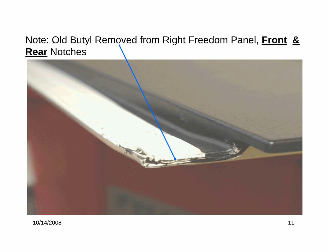
Note: Old Butyl Removed from Right Freedom Panel, Front & Rear Notches
10/14/2008 12
Place Right Freedom Panel Upside down on a covered work surface to prevent paint Scratching.
Freedom Panel Notch Butyl installation
10/14/2008 13
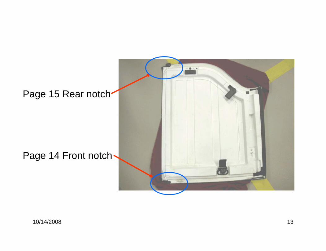
Page 14 Front notch
Page 15 Rear notch
10/14/2008 14
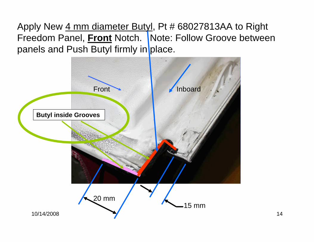
Apply New 4 mm diameter Butyl, Pt # 68027813AA to Right Freedom Panel, Front Notch. Note: Follow Groove between panels and Push Butyl firmly in place.
Front Inboard
20 mm15 mm
Butyl inside Grooves
10/14/2008 15
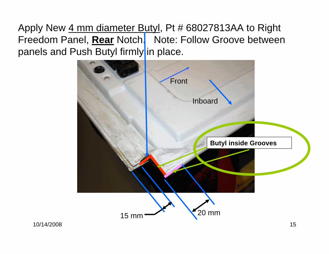
Apply New 4 mm diameter Butyl, Pt # 68027813AA to Right Freedom Panel, Rear Notch. Note: Follow Groove between panels and Push Butyl firmly in place.
20 mm15 mm
Front
Butyl inside Grooves
Inboard
10/14/2008 16
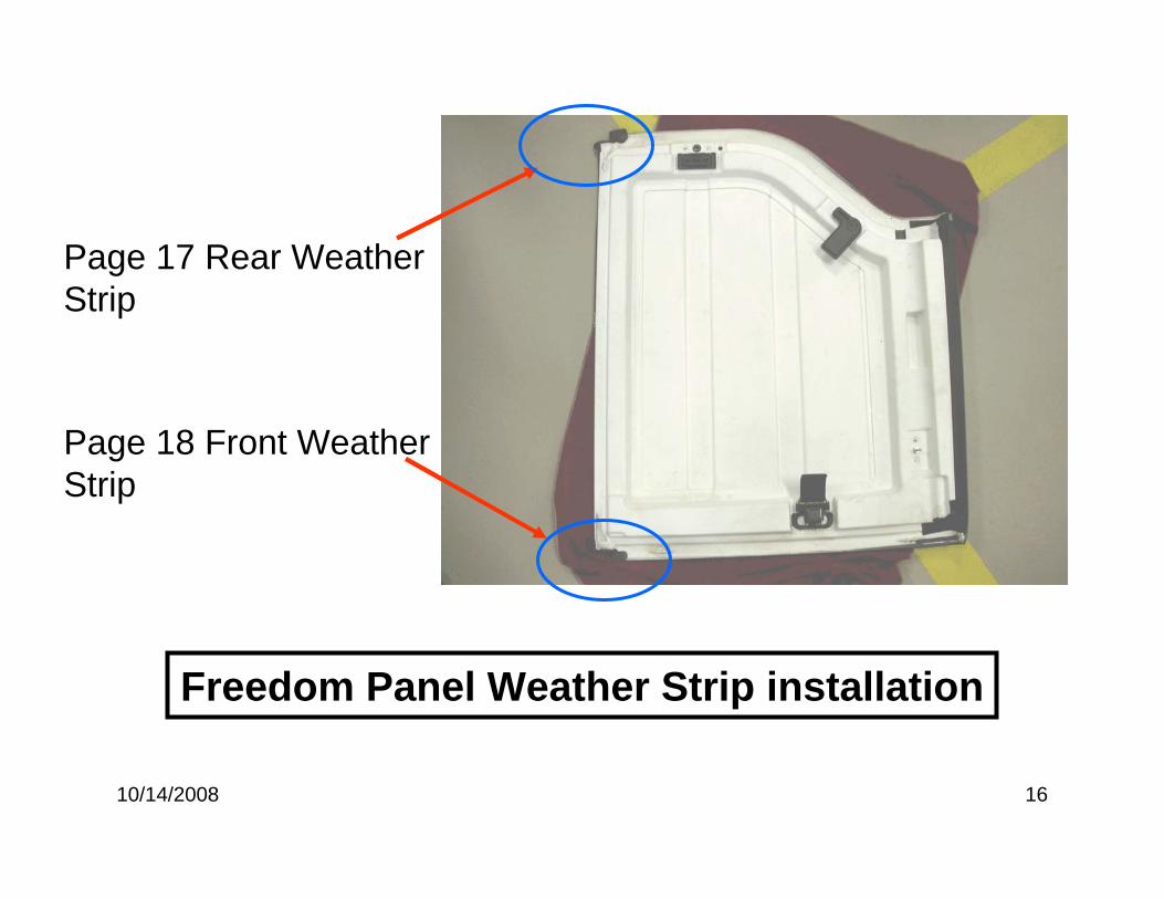
Page 18 Front Weather Strip
Page 17 Rear Weather Strip
Freedom Panel Weather Strip installation
10/14/2008 17
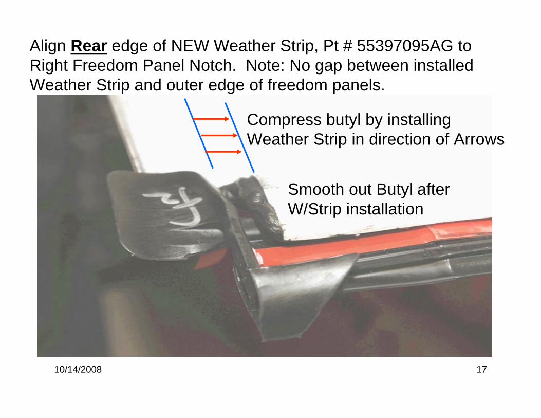
Align Rear edge of NEW Weather Strip, Pt # 55397095AG to Right Freedom Panel Notch. Note: No gap between installed Weather Strip and outer edge of freedom panels.
Compress butyl by installing Weather Strip in direction of Arrows
Smooth out Butyl after W/Strip installation
10/14/2008 18
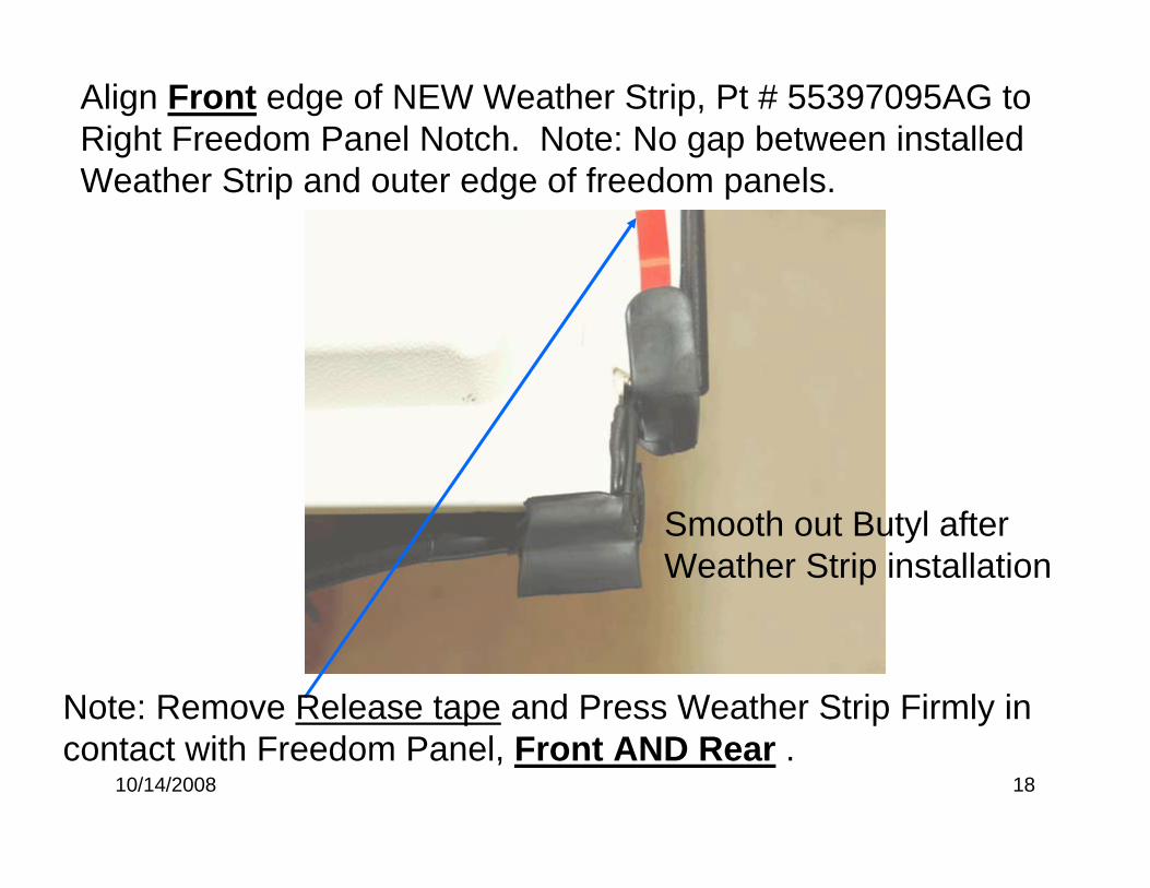
Align Front edge of NEW Weather Strip, Pt # 55397095AG to Right Freedom Panel Notch. Note: No gap between installed Weather Strip and outer edge of freedom panels.
Note: Remove Release tape and Press Weather Strip Firmly in contact with Freedom Panel, Front AND Rear .
Smooth out Butyl after Weather Strip installation
10/14/2008 19
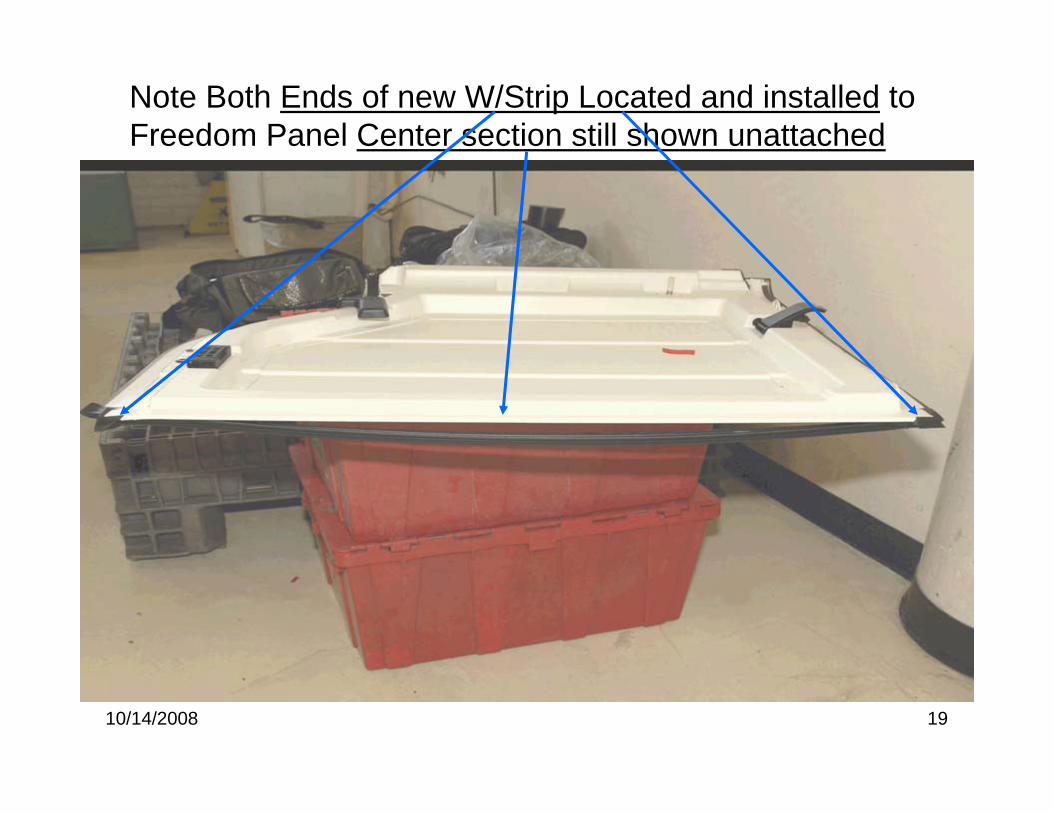
Note Both Ends of new W/Strip Located and installed to Freedom Panel Center section still shown unattached
10/14/2008 20
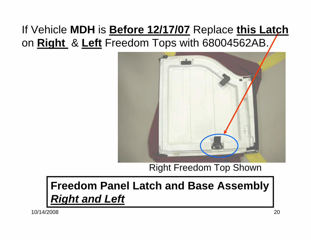
Freedom Panel Latch and Base Assembly Right and Left
If Vehicle MDH is Before 12/17/07 Replace this Latchon Right & Left Freedom Tops with 68004562AB.
Right Freedom Top Shown
10/14/2008 21
Flip Right Freedom Panel over to complete Weather Strip installation.
10/14/2008 22
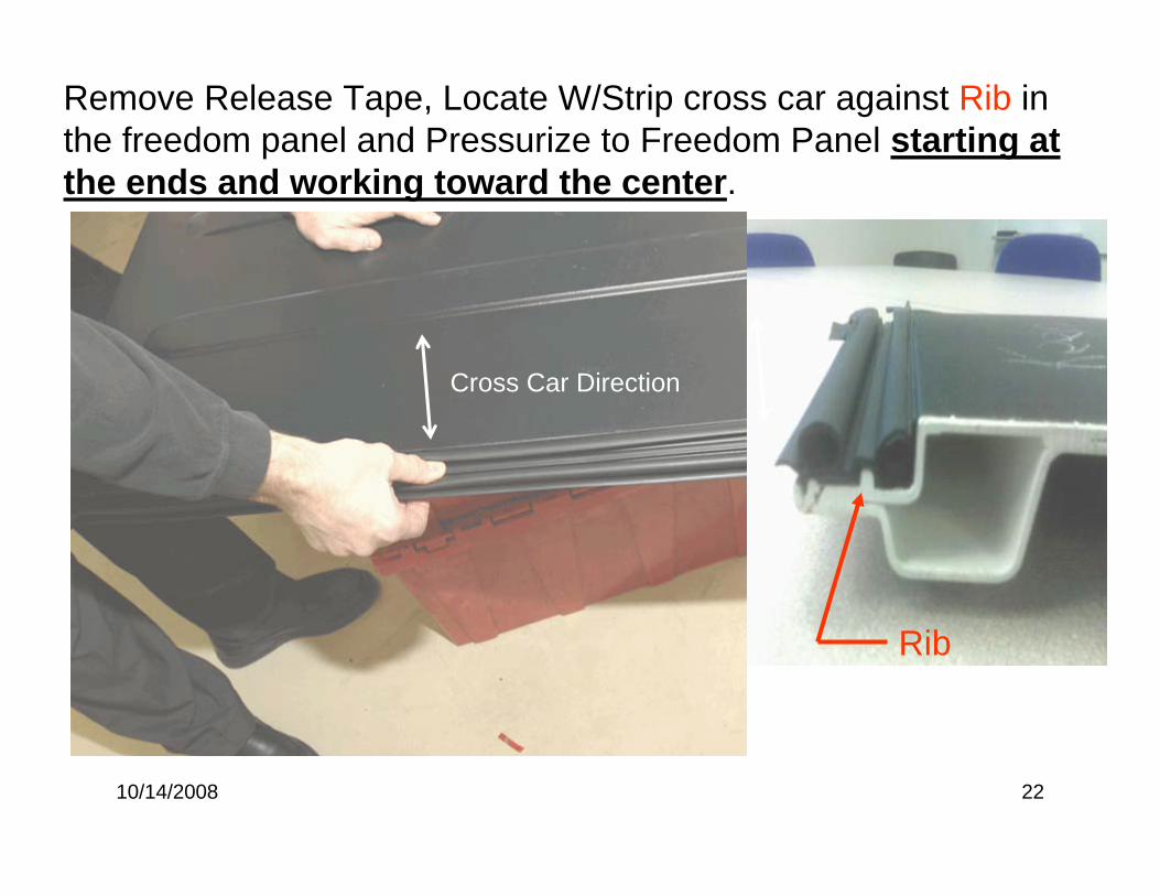
Remove Release Tape, Locate W/Strip cross car against Rib in the freedom panel and Pressurize to Freedom Panel starting at the ends and working toward the center.
Cross Car Direction
Rib
10/14/2008 23
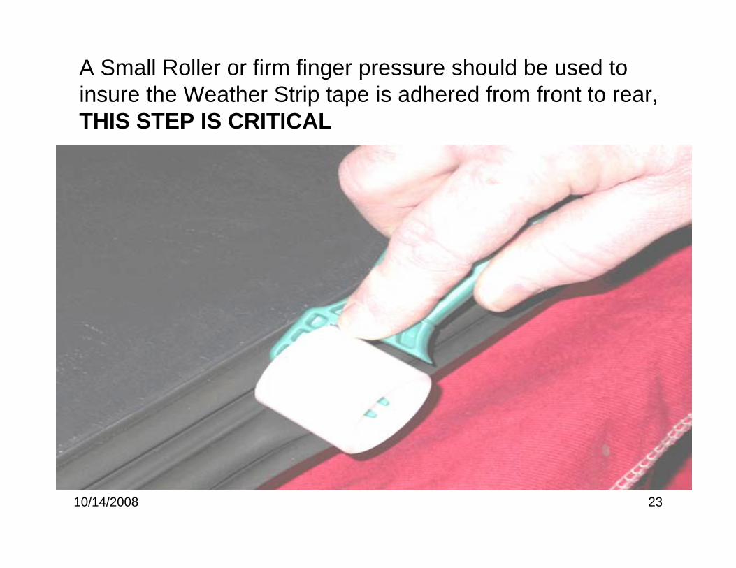
A Small Roller or firm finger pressure should be used to insure the Weather Strip tape is adhered from front to rear, THIS STEP IS CRITICAL
10/14/2008 24
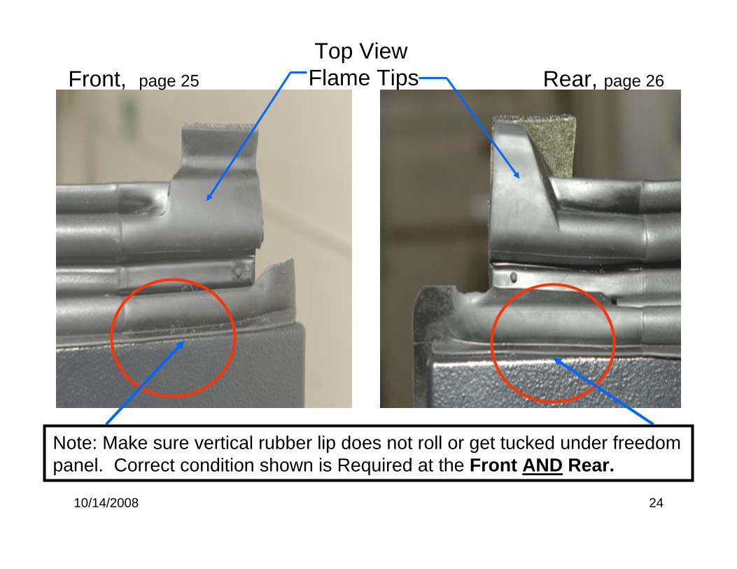
Top View Flame TipsFront, page 25 Rear, page 26
Note: Make sure vertical rubber lip does not roll or get tucked under freedom panel. Correct condition shown is Required at the Front AND Rear.
10/14/2008 25
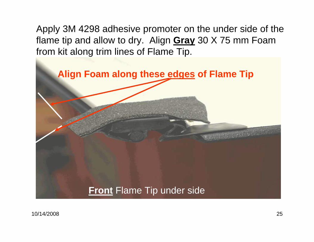
Apply 3M 4298 adhesive promoter on the under side of the flame tip and allow to dry. Align Gray 30 X 75 mm Foam from kit along trim lines of Flame Tip.
Front Flame Tip under side
Align Foam along these edges of Flame Tip
10/14/2008 26
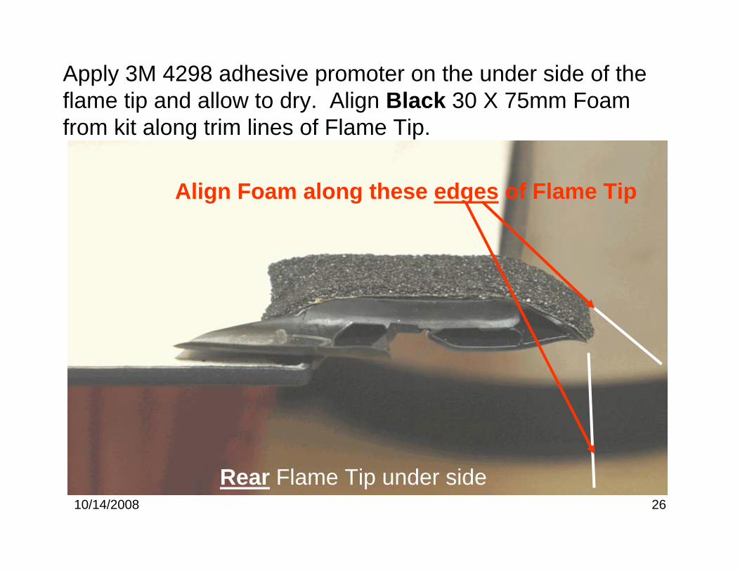
Apply 3M 4298 adhesive promoter on the under side of the flame tip and allow to dry. Align Black 30 X 75mm Foam from kit along trim lines of Flame Tip.
Rear Flame Tip under side
Align Foam along these edges of Flame Tip
10/14/2008 27
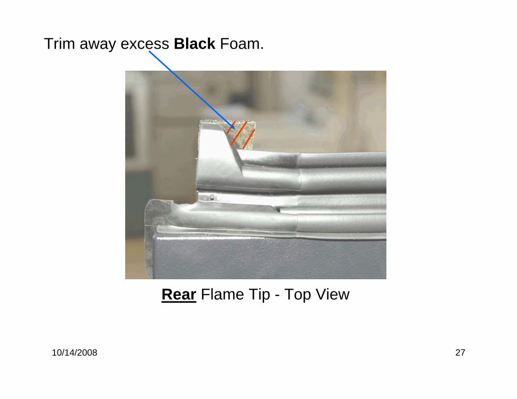
Trim away excess Black Foam.
Rear Flame Tip - Top View
10/14/2008 28
Left Freedom Panel
Rear Inboard Corner Butyl & Foam installation
Place Left Freedom Panel Upside down on a covered work surface to prevent paint Scratching
Clean Seal Surface with: 3M General Purpose Adhesive Cleaner or Kent Products Acrysol, (if available) and allow to dry completely. Rough up Seal Surface with Medium Scotch Bright pad. Wipe Seal Surface with Alcohol and allow to dry completely
10/14/2008 29
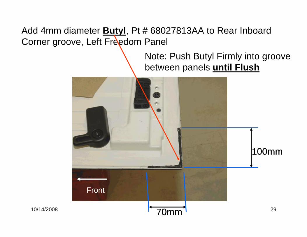
Add 4mm diameter Butyl, Pt # 68027813AA to Rear Inboard Corner groove, Left Freedom Panel
100mm
70mm
Outboard
Front
100mm
70mm
Front
Note: Push Butyl Firmly into groove between panels until Flush
10/14/2008 30
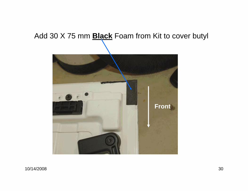
Add 30 X 75 mm Black Foam from Kit to cover butyl
Front
10/14/2008 31
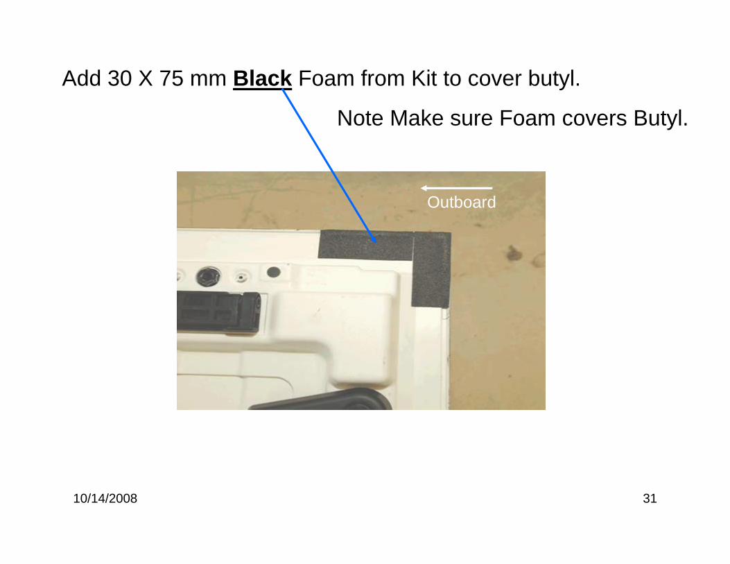
Add 30 X 75 mm Black Foam from Kit to cover butyl.
Note Make sure Foam covers Butyl.
Outboard
10/14/2008 32
Left Freedom Panel complete.
Note: REMINDER Refer to Page 20 If Vehicle MDH is Before 12/17/07 . Replace Latch on Right & LeftFreedom Top with 68004562AB.
10/14/2008 1
JK “A” Pillar- Header Weather Strip
Water Leak RepairReference TSB # 23-025-08 As Required for additional Repair Information

10/14/2008 2
This package does not address water that drips into the Vehicle when the door is open.
This is a normal condition!
*Please note: This package addresses water leaks that come from
inside the vehicle when the door is closed.
10/14/2008 3
1
2
3
4
5
6
1.Windshield header seal2.Windshield to cowl seal3.Front door weatherseal4.B pillar mucket5.Hard top seal6.Center freedom panel seal
Outside View
10/14/2008 4
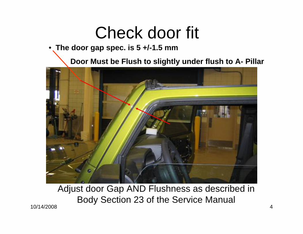
• The door gap spec. is 5 +/-1.5 mm
Door Must be Flush to slightly under flush to A- Pillar
Check door fit
Adjust door Gap AND Flushness as described in Body Section 23 of the Service Manual
10/14/2008 5
Header Weather Strip
Weather Strip Removal & Butyl Clean Up
Remove Header Weather Strip from Body sheet metal and clean up / remove all traces of old Tape and Butyl from painted sheet metal surfaces before reinstallation of butyl bead and new weather strip. Clean Seal Surface with: 3M General Purpose Adhesive Cleaner or Kent Products Acrysol, (if available) and allow to dry completely.
10/14/2008 6
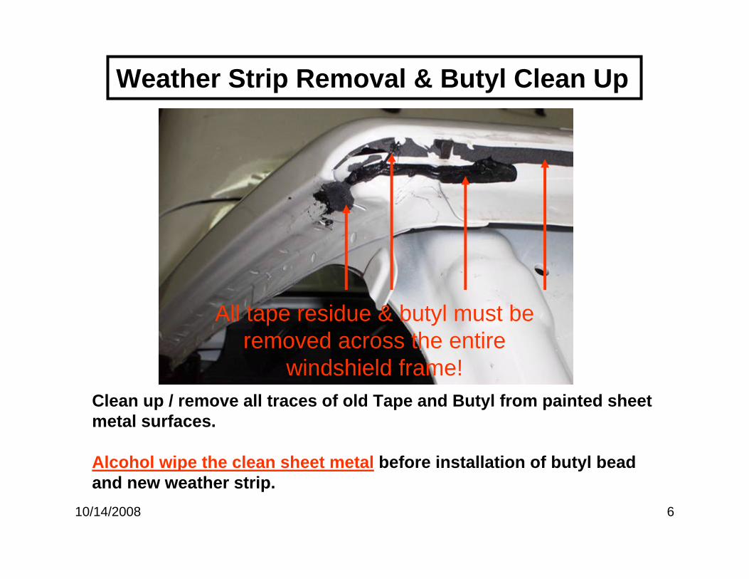
Weather Strip Removal & Butyl Clean Up
Clean up / remove all traces of old Tape and Butyl from painted sheet metal surfaces.
Alcohol wipe the clean sheet metal before installation of butyl bead and new weather strip.
All tape residue & butyl must be removed across the entire
windshield frame!
10/14/2008 7
Header Weather Strip
Butyl Placement and New Weather Strip Installation.
Right Side Shown on Pages 8, 9, & 10.
Left Side Not Shown but symmetrical / identical to Right
10/14/2008 8
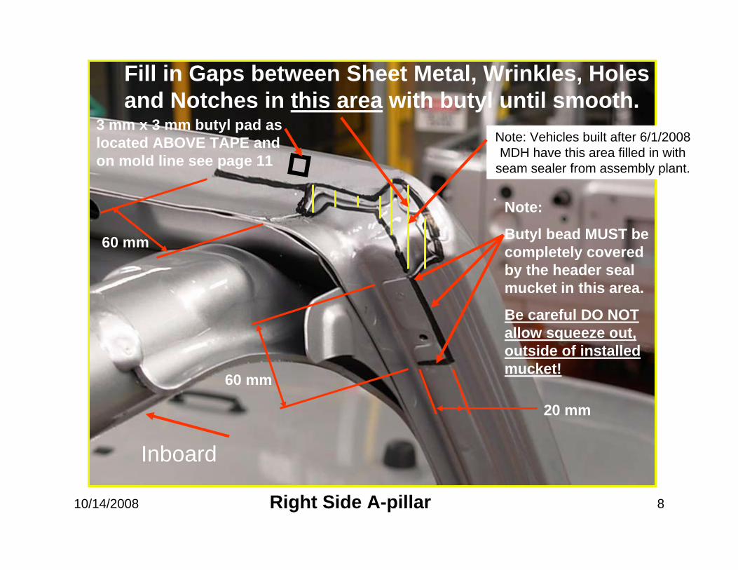
60 mm
60 mm
Inboard
20 mm
Fill in Gaps between Sheet Metal, Wrinkles, Holes and Notches in this area with butyl until smooth.
Right Side A-pillar
3 mm x 3 mm butyl pad as located ABOVE TAPE and on mold line see page 11
Note:
Butyl bead MUST be completely covered by the header seal mucket in this area.
Be careful DO NOT allow squeeze out, outside of installed mucket!
Note: Vehicles built after 6/1/2008 MDH have this area filled in with
seam sealer from assembly plant.
10/14/2008 9
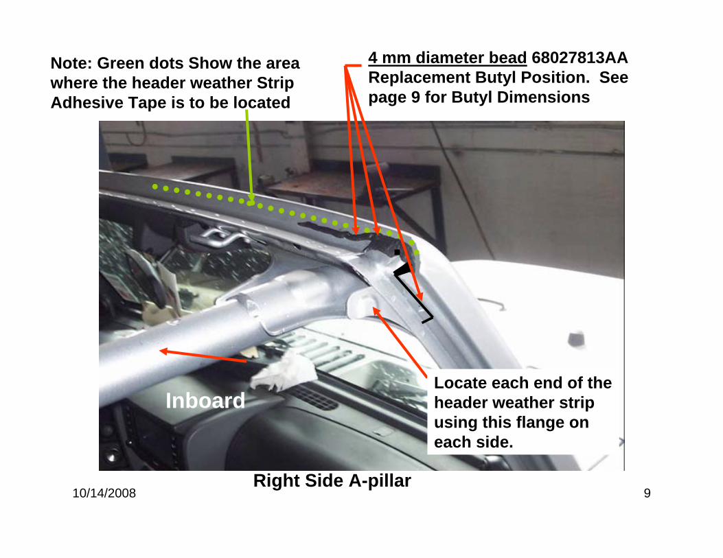
4 mm diameter bead 68027813AAReplacement Butyl Position. See page 9 for Butyl Dimensions
Inboard
Right Side A-pillar
Note: Green dots Show the area where the header weather Strip Adhesive Tape is to be located
Locate each end of the header weather strip using this flange on each side.
10/14/2008 10
Locate and install NEW Weather Strip, Pt # Strip 55397454AB.
Remove Release tape and Pressurize Weather Strip Firmly in contact with Header Sheet Metal to smooth out adhesive tape and butyl, starting at the ends and working toward the center. A small Roller or firm finger pressure should be used to insure the Weather Strip tape is adhered completely from side to side, THIS STEP IS CRITICAL
Gently pull weather strip rearward at mold line shown on page 9 and insert a 3 mm x 3 mm square piece of butyl .
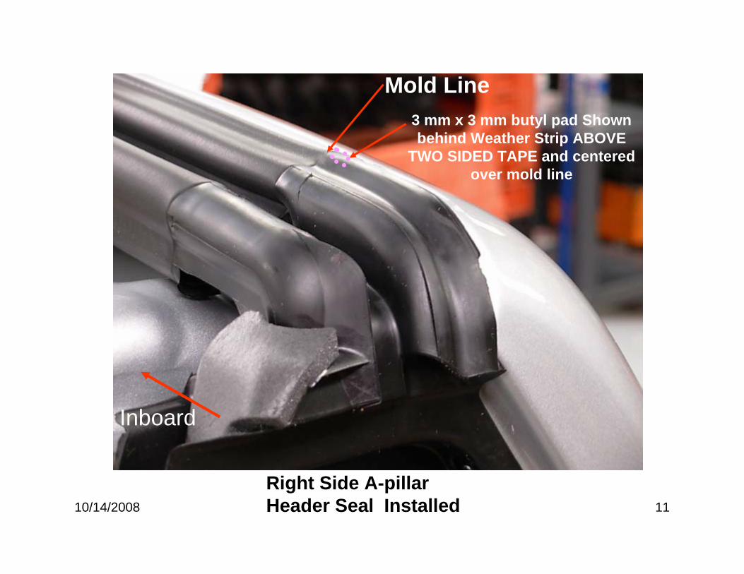
10/14/2008 11
Right Side A-pillar Header Seal Installed
Mold Line3 mm x 3 mm butyl pad Shown behind Weather Strip ABOVE
TWO SIDED TAPE and centered over mold line
Inboard
9/4/2008 1
JK -B Pillar-Water Leak Repair
9/4/2008 2
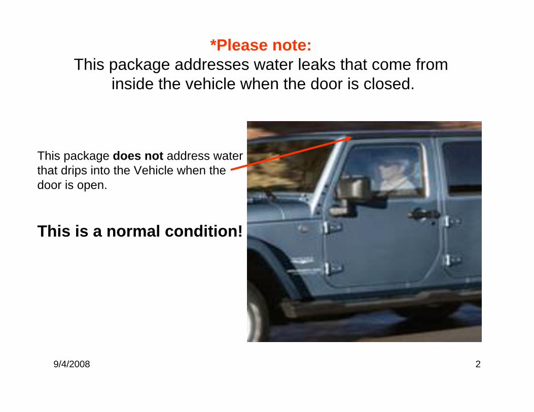
This package does not address water that drips into the Vehicle when the door is open.
This is a normal condition!
*Please note: This package addresses water leaks that come from
inside the vehicle when the door is closed.
9/4/2008 3
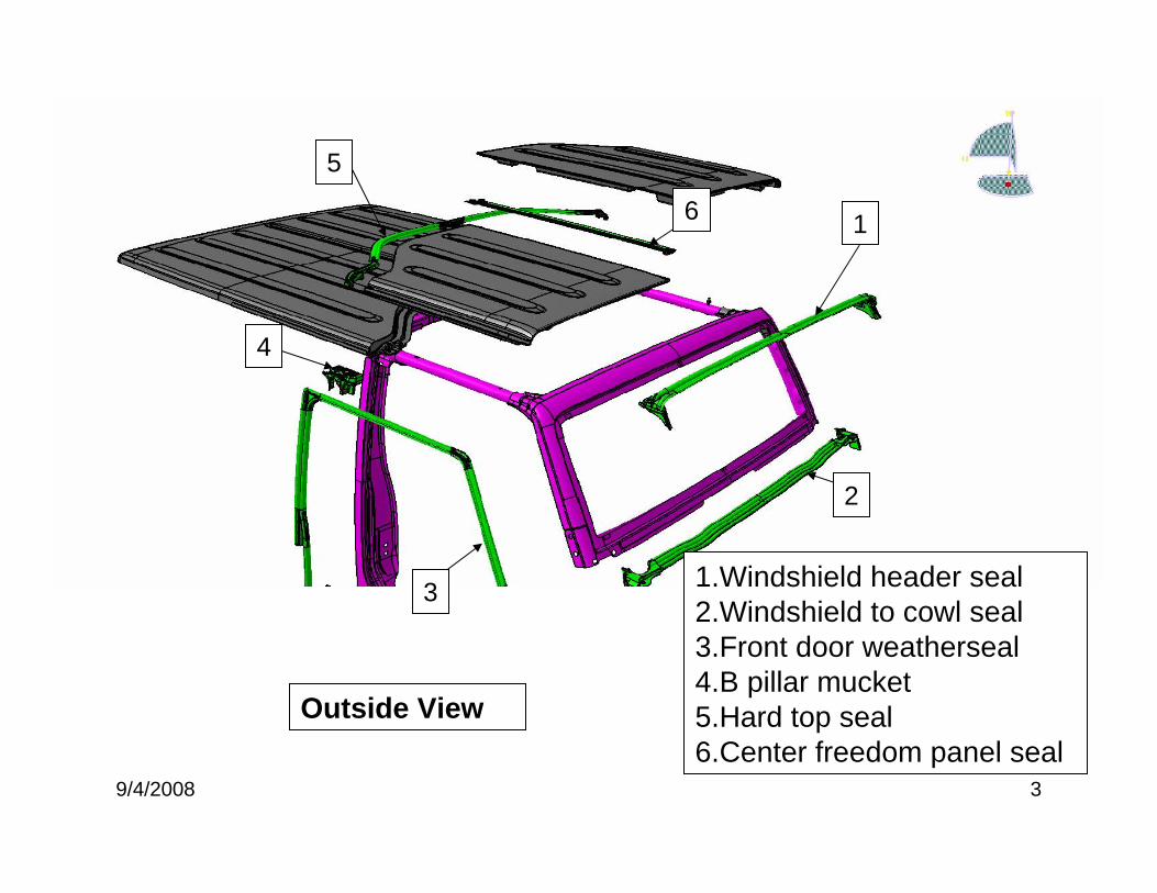
1
2
3
4
5
6
1.Windshield header seal2.Windshield to cowl seal3.Front door weatherseal4.B pillar mucket5.Hard top seal6.Center freedom panel seal
Outside View
9/4/2008 4
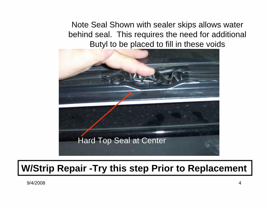
Hard Top Seal at Center
Note Seal Shown with sealer skips allows water behind seal. This requires the need for additional
Butyl to be placed to fill in these voids
W/Strip Repair -Try this step Prior to Replacement
9/4/2008 5
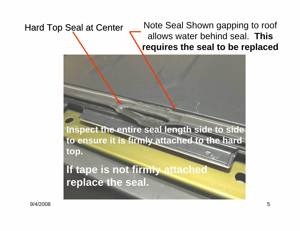
Hard Top Seal at Center Note Seal Shown gapping to roof allows water behind seal. This
requires the seal to be replaced
Hard Top Seal at Center
Inspect the entire seal length side to side to ensure it is firmly attached to the hard top.
If tape is not firmly attached replace the seal.
9/4/2008 6
Hard Top Weather Strip
Weather Strip Removal & Butyl Clean Up
Remove Hard Top Weather Strip from Hard Top and clean up / remove all traces of old Tape and Butyl from painted surfaces before reinstallation of new weather strip. Clean Seal Surface with: 3M General Purpose Adhesive Cleaner or Kent Products Acrysol, (if available) and allow to dry completely.
9/4/2008 7
Hard Top Weather StripAlcohol wipe the clean painted surfaces, And Allow Alcohol to dry completely before insallation of new weather strip.
Locate & install NEW Weather Strip, Pt # 55397058AI (2 DR) or 55397046AF (4 DR). Place seal tight against roof / without gaps as shown on page 5. Remove Release tape & Pressurize Weather Strip Firmly in contact with Roof to smooth out adhesive tape, Make sure adhesive tape is FIRMLY PRESSURIZED against the roof panel while maintaining a zero gap condition from side to side. A small Roller or firm finger pressure should be used to insure the Weather Strip tape is adhered completely side to side, THIS STEP IS CRITICAL
9/4/2008 8
B- Pillar Weather Strip
Mucket Removal, Clean Up, Butyl & Mucket install and Mucket drain hole and Dam rework
Remove B - Pillar Mucket Weather Strip from body and clean up / remove all traces of old Tape and Butyl from painted surfaces before reinstallation of butyl bead and new weather strip. Clean Seal Surface with: 3M General Purpose Adhesive Cleaner or Kent Products Acrysol, (if available) and allow to dry completely.
PAGE / S 9 & 11 Show the RIGHT SIDE B–PILLAR & PAGE 12 SHOWS THE LEFT SIDE, THESE REWORKS MUST BE DONE ON BOTH SIDES OF THE TRUCK
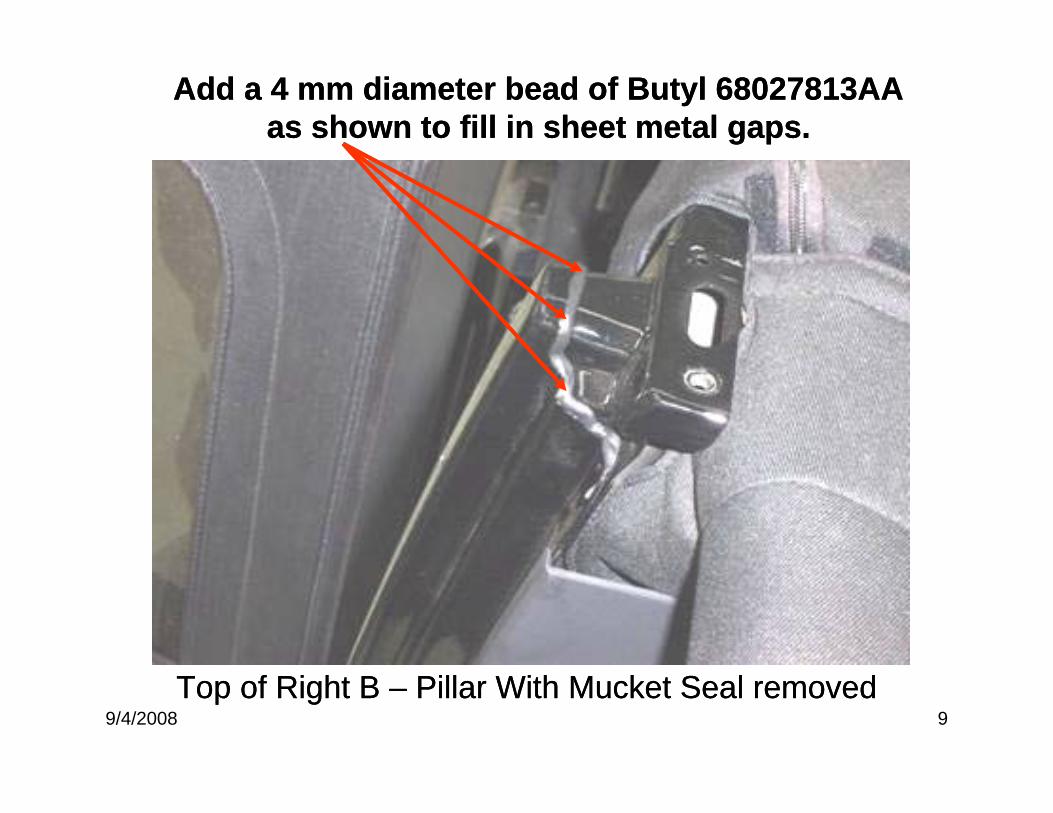
9/4/2008 9Top of Right B – Pillar With Mucket Seal removed
Add a 4 mm diameter bead of Butyl 68027813AA as shown to fill in sheet metal gaps.
Top of Right B – Pillar With Mucket Seal removed
Add a 4 mm diameter bead of Butyl 68027813AA as shown to fill in sheet metal gaps.
9/4/2008 10
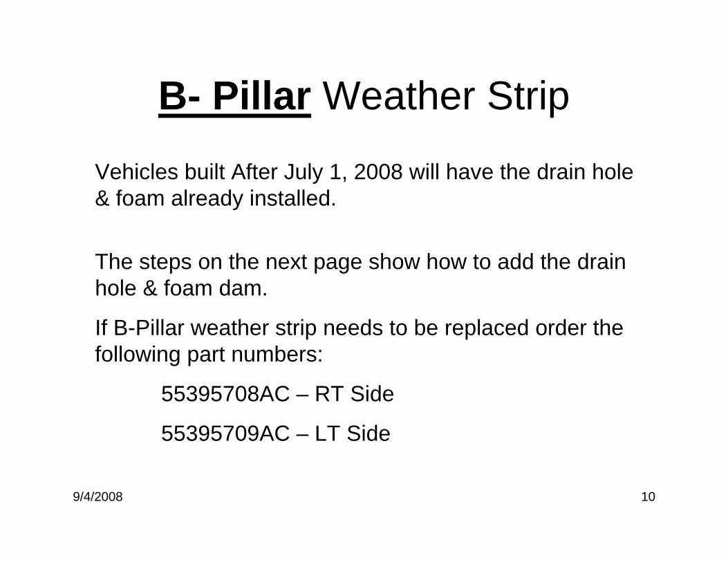
B- Pillar Weather Strip
Vehicles built After July 1, 2008 will have the drain hole & foam already installed.
The steps on the next page show how to add the drain hole & foam dam.
If B-Pillar weather strip needs to be replaced order the following part numbers:
55395708AC – RT Side
55395709AC – LT Side
9/4/2008 11
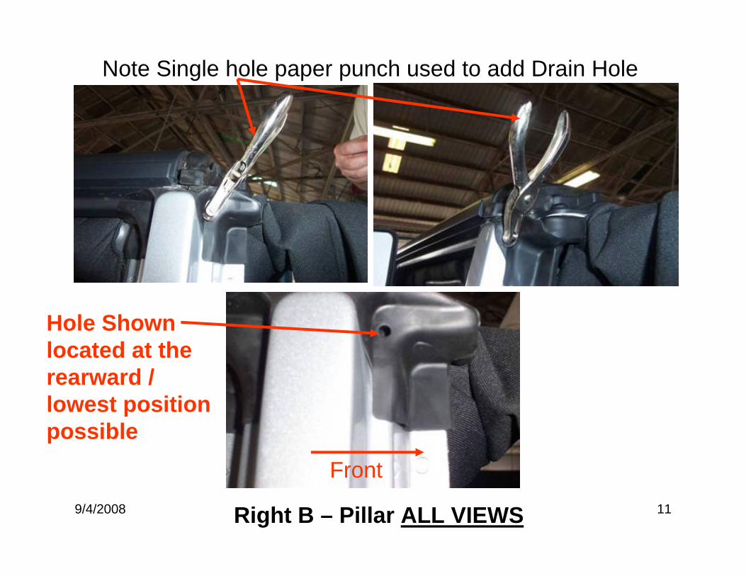
Note Single hole paper punch used to add Drain Hole
Right B – Pillar ALL VIEWS
Front
Hole Shown located at the rearward / lowest position possible
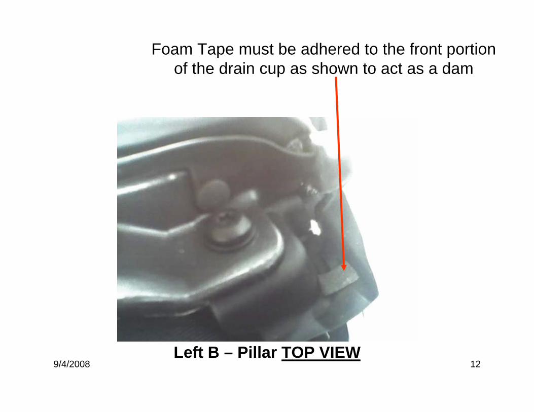
9/4/2008 12Left B – Pillar TOP VIEW
Foam Tape must be adhered to the front portion of the drain cup as shown to act as a dam
9/4/2008 1
JK –Half Doors-Water Leak Repair
9/4/2008 2
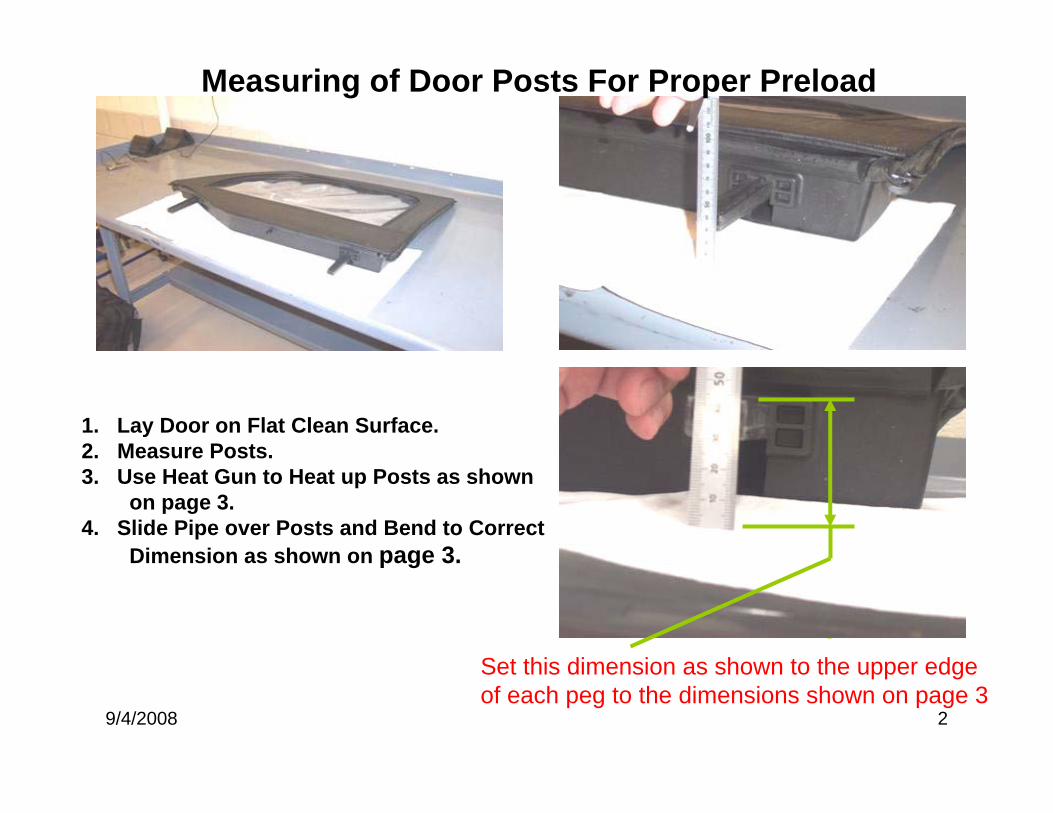
Measuring of Door Posts For Proper Preload
1. Lay Door on Flat Clean Surface.2. Measure Posts.3. Use Heat Gun to Heat up Posts as shown
on page 3.4. Slide Pipe over Posts and Bend to Correct
Dimension as shown on page 3.
Set this dimension as shown to the upper edge of each peg to the dimensions shown on page 3
9/4/2008 3
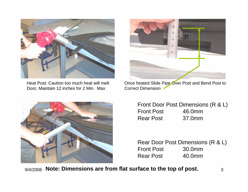
Heat Post: Caution too much heat will melt Door, Maintain 12 inches for 2 Min. Max
Once heated Slide Pipe Over Post and Bend Post to Correct Dimension
Front Door Post Dimensions (R & L)Front Post 46.0mmRear Post 37.0mm
Rear Door Post Dimensions (R & L)Front Post 30.0mmRear Post 40.0mm
Note: Dimensions are from flat surface to the top of post.
9/4/2008 4
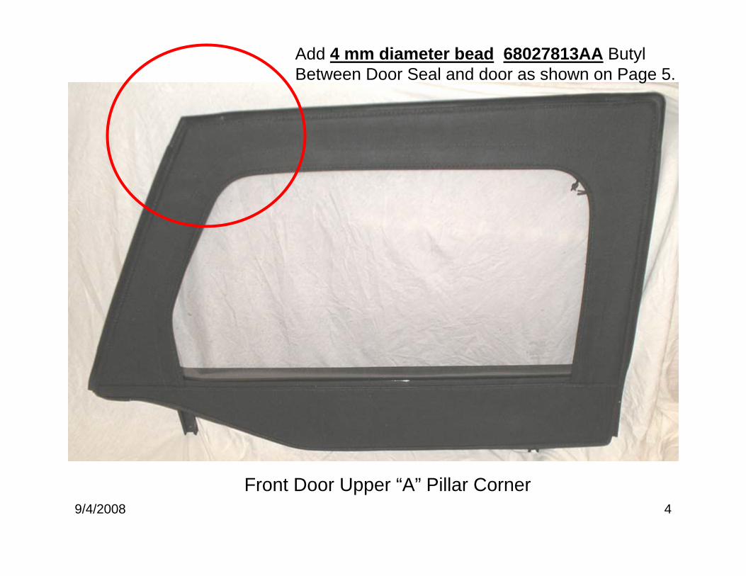
Front Door Upper “A” Pillar Corner
Add 4 mm diameter bead 68027813AA Butyl Between Door Seal and door as shown on Page 5.
9/4/2008 5
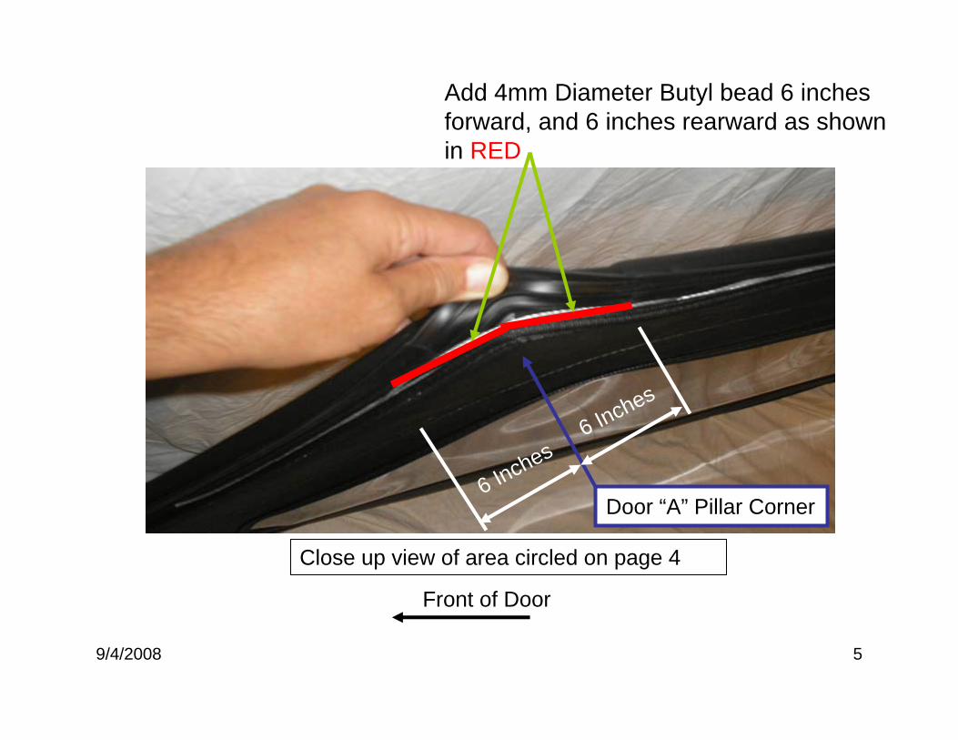
Door “A” Pillar Corner
6 Inches
6 Inches
Add 4mm Diameter Butyl bead 6 inches forward, and 6 inches rearward as shown in RED
Front of Door
Close up view of area circled on page 4
9/4/2008 6
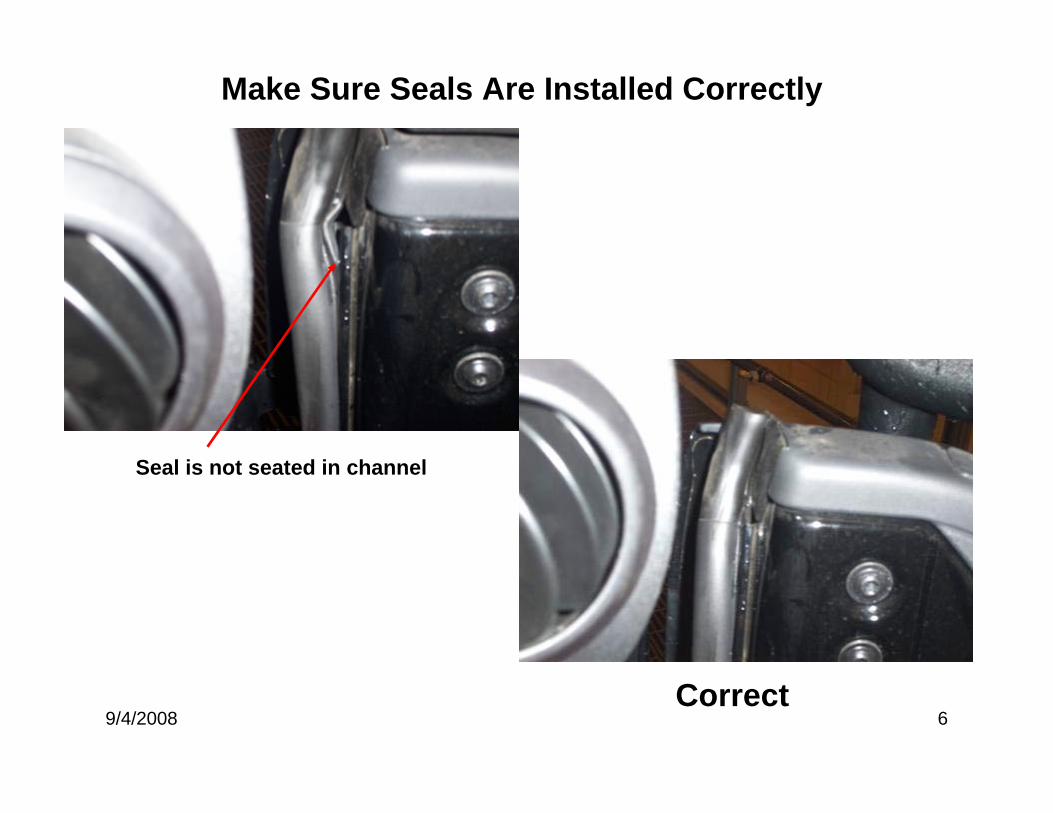
Make Sure Seals Are Installed Correctly
Seal is not seated in channel
Correct
9/4/2008 7
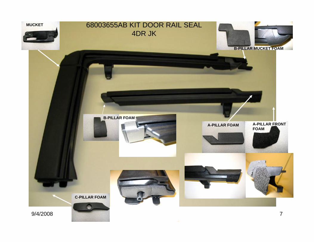
68003655AB KIT DOOR RAIL SEAL4DR JK
MUCKET
B-PILLAR FOAM
C-PILLAR FOAM
A-PILLAR FOAM A-PILLAR FRONTFOAM
B-PILLAR MUCKET FOAM

9/4/2008 8
68003645AB KIT DOOR RAIL SEAL2DR JK
MUCKET
A-PILLAR FOAM
B-PILLAR FOAM
A-PILLAR FRONTFOAM

10/14/2008 1
JK – Soft Top Water Leak Repair Tips
10/14/2008 2
Header Seal Cup Folded under
Correct
10/14/2008 3
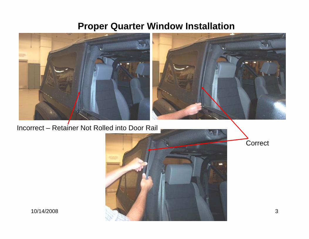
Proper Quarter Window Installation
Incorrect – Retainer Not Rolled into Door Rail
Correct
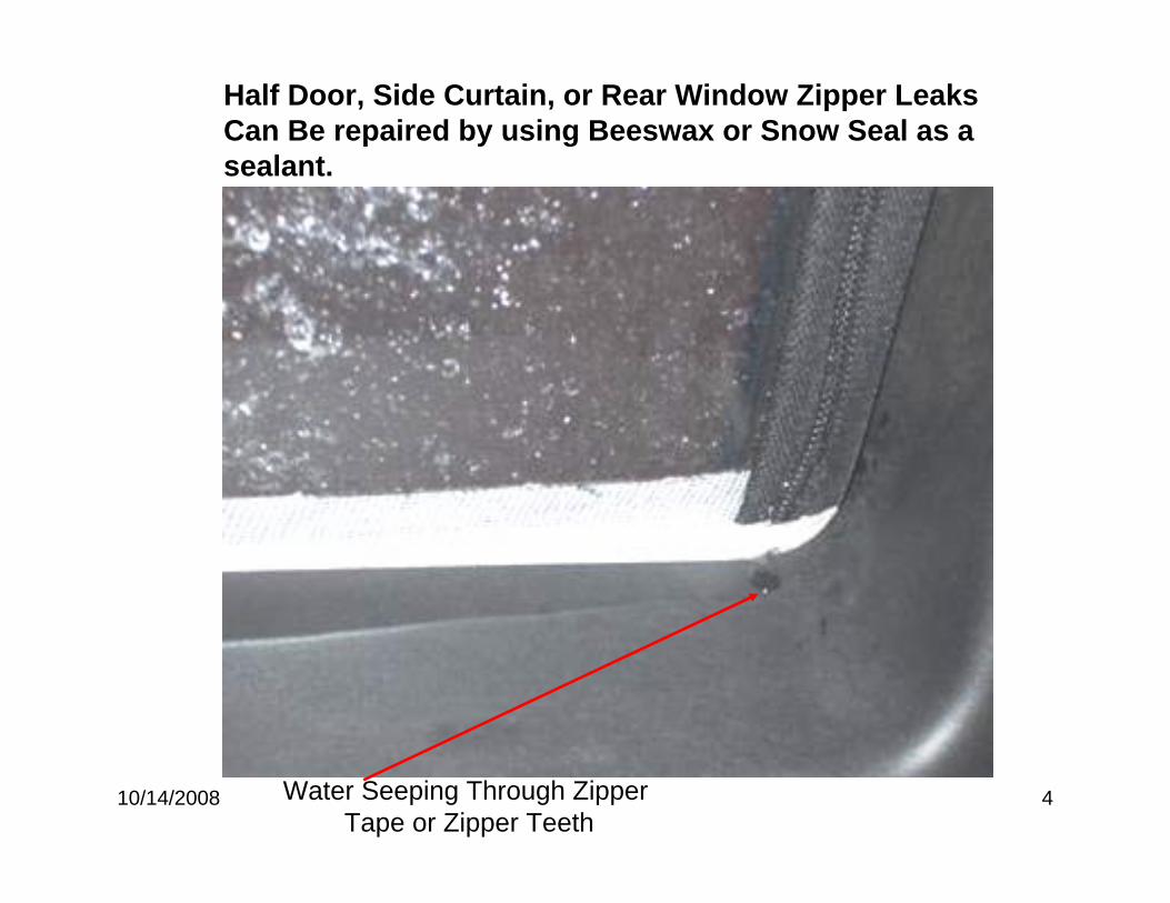
10/14/2008 4Water Seeping Through ZipperTape or Zipper Teeth
Half Door, Side Curtain, or Rear Window Zipper Leaks Can Be repaired by using Beeswax or Snow Seal as a sealant.

10/14/2008 5
68003655AB KIT DOOR RAIL SEAL4DR JK
MUCKET
B-PILLAR FOAM
C-PILLAR FOAM
A-PILLAR FOAM A-PILLAR FRONTFOAM
B-PILLAR MUCKET FOAM
10/14/2008 6
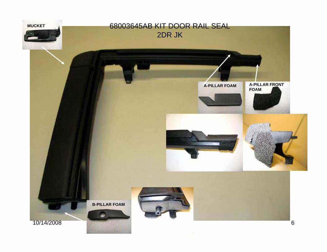
68003645AB KIT DOOR RAIL SEAL2DR JK
MUCKET
A-PILLAR FOAM
B-PILLAR FOAM
A-PILLAR FRONTFOAM
Page 1 of 5
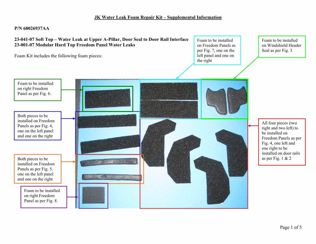
JK Water Leak Foam Repair Kit – Supplemental Information P/N 68026937AA 23-041-07 Soft Top – Water Leak at Upper A-Pillar, Door Seal to Door Rail Interface 23-001-07 Modular Hard Top Freedom Panel Water Leaks Foam Kit includes the following foam pieces:
Foam to be installed on Windshield Header Seal as per Fig. 3
Foam to be installed on Freedom Panels as per Fig. 7, one on the left panel and one on the right
Both pieces to be installed on Freedom Panels as per Fig. 4, one on the left panel and one on the right
Both pieces to be installed on Freedom Panels as per Fig. 5, one on the left panel and one on the right
Foam to be installed on right Freedom Panel as per Fig. 6.
All four pieces (two right and two left) to be installed on Freedom Panels as per Fig. 4, one left and one right to be installed on door rails as per Fig. 1 & 2
Foam to be installed on right Freedom Panel as per Fig. 8.
Page 2 of 5
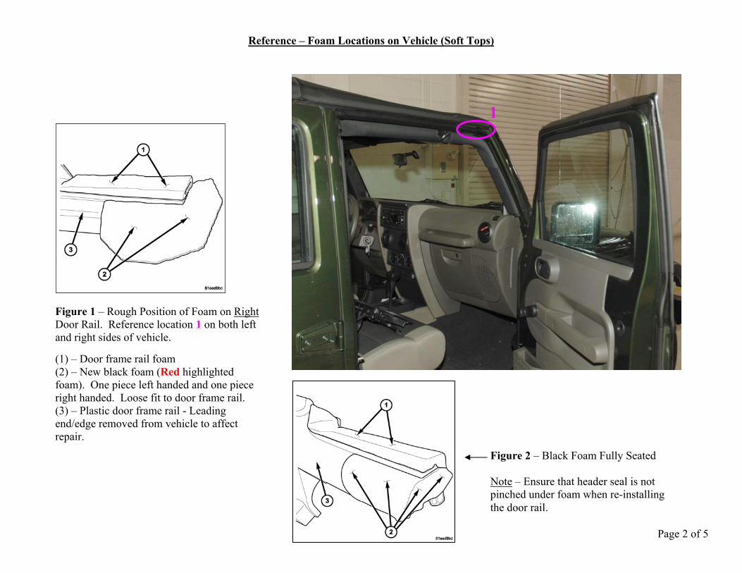
Reference – Foam Locations on Vehicle (Soft Tops)
Figure 1 – Rough Position of Foam on Right Door Rail. Reference location 1 on both left and right sides of vehicle. (1) – Door frame rail foam (2) – New black foam (Red highlighted foam). One piece left handed and one piece right handed. Loose fit to door frame rail. (3) – Plastic door frame rail - Leading end/edge removed from vehicle to affect repair.
Figure 2 – Black Foam Fully Seated Note – Ensure that header seal is not pinched under foam when re-installing the door rail.
1
Page 3 of 5
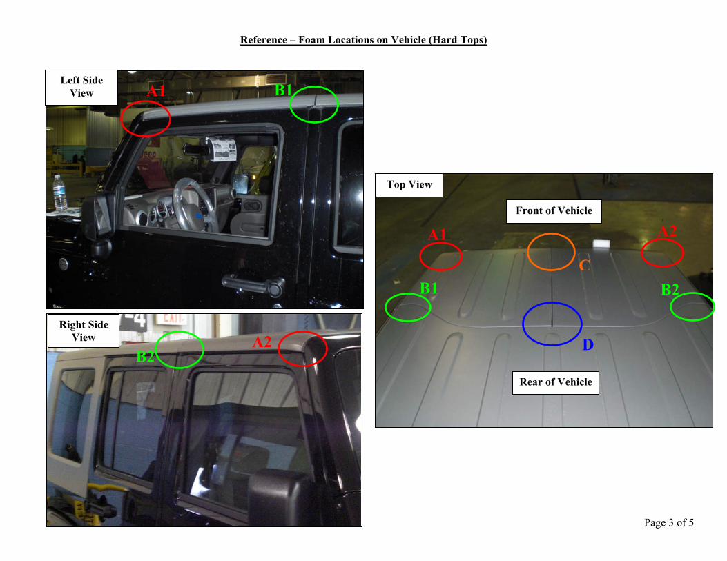
Reference – Foam Locations on Vehicle (Hard Tops)
Left Side View
Right Side View
Top View
Front of Vehicle
Rear of Vehicle
A1
A2
B1
B2
C
D
A1 A2
B2 B1
Page 4 of 5
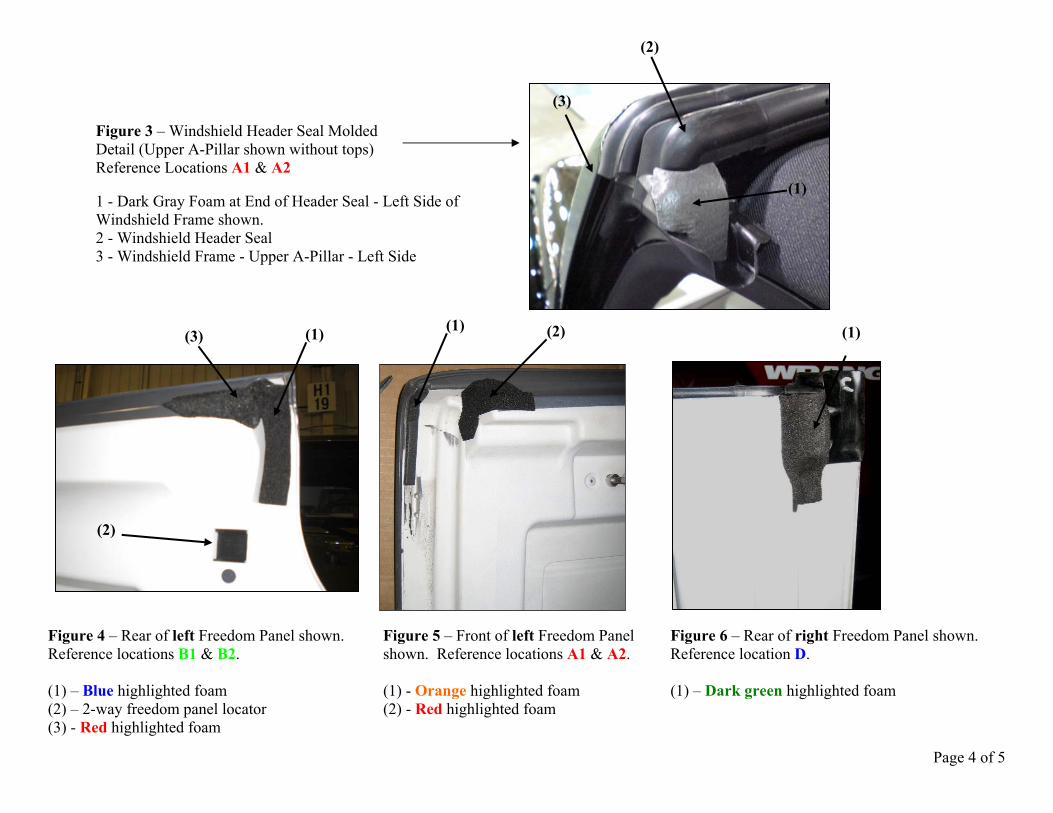
Figure 3 – Windshield Header Seal Molded Detail (Upper A-Pillar shown without tops) Reference Locations A1 & A2 1 - Dark Gray Foam at End of Header Seal - Left Side of Windshield Frame shown. 2 - Windshield Header Seal 3 - Windshield Frame - Upper A-Pillar - Left Side
Figure 4 – Rear of left Freedom Panel shown. Figure 5 – Front of left Freedom Panel Figure 6 – Rear of right Freedom Panel shown. Reference locations B1 & B2. shown. Reference locations A1 & A2. Reference location D. (1) – Blue highlighted foam (1) - Orange highlighted foam (1) – Dark green highlighted foam (2) – 2-way freedom panel locator (2) - Red highlighted foam (3) - Red highlighted foam
(1) (3)
(2)
(1)(1) (2)
(1)
(2)
(3)
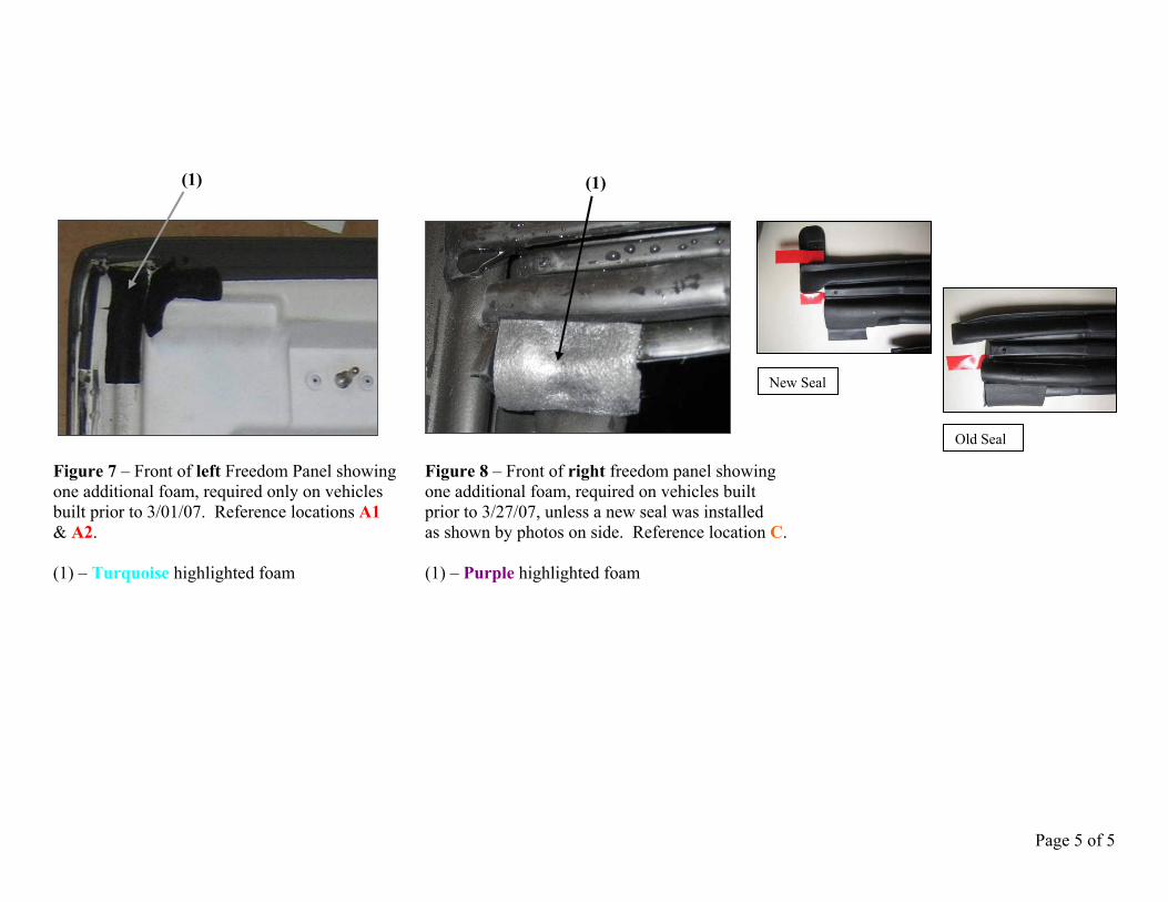
Page 5 of 5
Figure 7 – Front of left Freedom Panel showing Figure 8 – Front of right freedom panel showing one additional foam, required only on vehicles one additional foam, required on vehicles built built prior to 3/01/07. Reference locations A1 prior to 3/27/07, unless a new seal was installed & A2. as shown by photos on side. Reference location C. (1) – Turquoise highlighted foam (1) – Purple highlighted foam
New Seal
Old Seal
(1) (1)
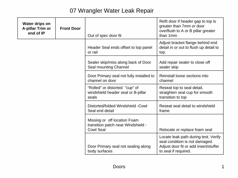
Doors 1
07 Wrangler Water Leak Repair
Water drips on A-pillar Trim or
end of IPFront Door
Out of spec door fit
Refit door if header gap to top is greater than 7mm or door overflush to A or B pillar greater than 1mm
Header Seal ends offset to top panel or rail
Adjust bracket flange behind end detail in or out to flush up detail to top.
Sealer skip/miss along back of Door Seal mounting Channel
Add repair sealer to close off sealer skip
Door Primary seal not fully installed to channel on door
Reinstall loose sections into channel
“Rolled” or distorted "cup" of windshield header seal or B-pillar seals
Reseat top to seal detail, straighten seal cup for smooth transition to top
Distorted/folded Windshield -Cowl Seal end detail
Reseat seal detail to windshield frame
Missing or off location Foam transition patch near Windshield -Cowl Seal Relocate or replace foam seal
Door Primary seal not sealing along body surfaces
Locate leak path during test. Verify seal condition is not damaged. Adjust door fit or add insert/stuffer to seal if required.
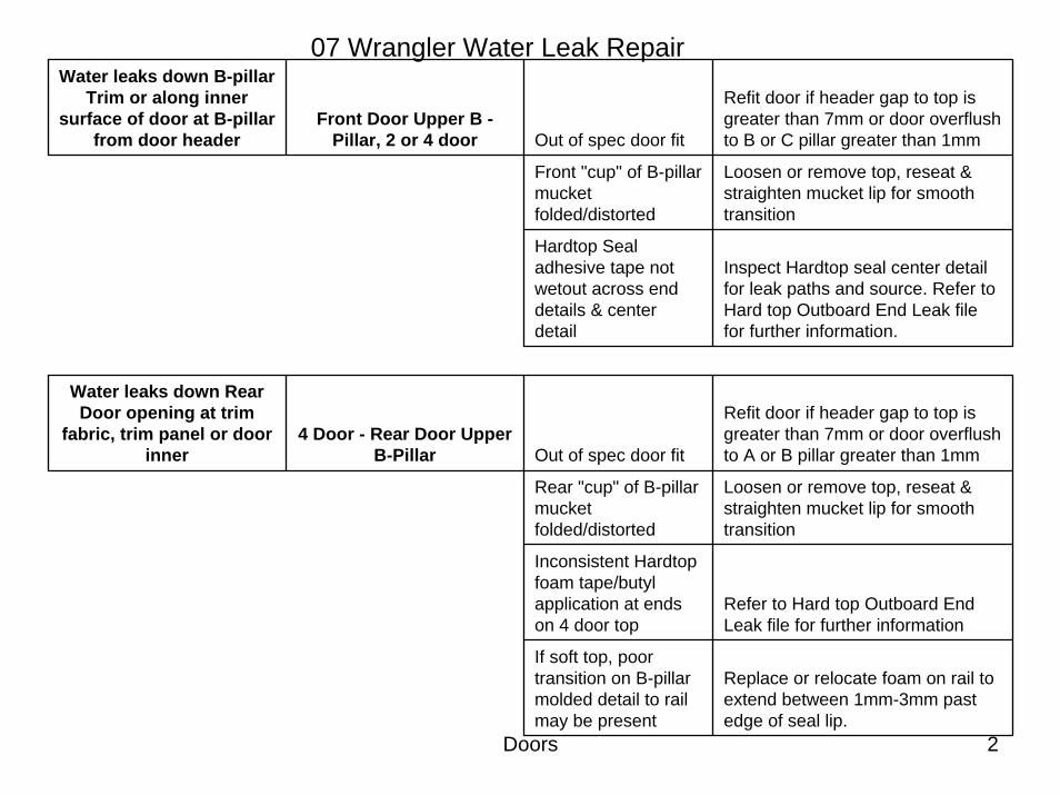
Doors 2
07 Wrangler Water Leak RepairWater leaks down B-pillar
Trim or along inner surface of door at B-pillar
from door header Front Door Upper B -
Pillar, 2 or 4 door Out of spec door fit
Refit door if header gap to top is greater than 7mm or door overflushto B or C pillar greater than 1mm
Front "cup" of B-pillar mucketfolded/distorted
Loosen or remove top, reseat & straighten mucket lip for smooth transition
Hardtop Seal adhesive tape not wetout across end details & center detail
Inspect Hardtop seal center detail for leak paths and source. Refer to Hard top Outboard End Leak file for further information.
Water leaks down Rear Door opening at trim
fabric, trim panel or door inner
4 Door - Rear Door Upper B-Pillar Out of spec door fit
Refit door if header gap to top is greater than 7mm or door overflushto A or B pillar greater than 1mm
Rear "cup" of B-pillar mucketfolded/distorted
Loosen or remove top, reseat & straighten mucket lip for smooth transition
Inconsistent Hardtop foam tape/butyl application at ends on 4 door top
Refer to Hard top Outboard End Leak file for further information
If soft top, poor transition on B-pillar molded detail to rail may be present
Replace or relocate foam on rail to extend between 1mm-3mm past edge of seal lip.
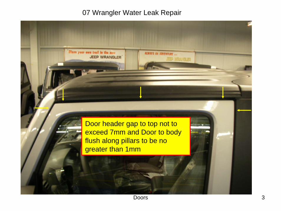
Doors 3
07 Wrangler Water Leak Repair
Door header gap to top not to exceed 7mm and Door to body flush along pillars to be no greater than 1mm
Doors 4
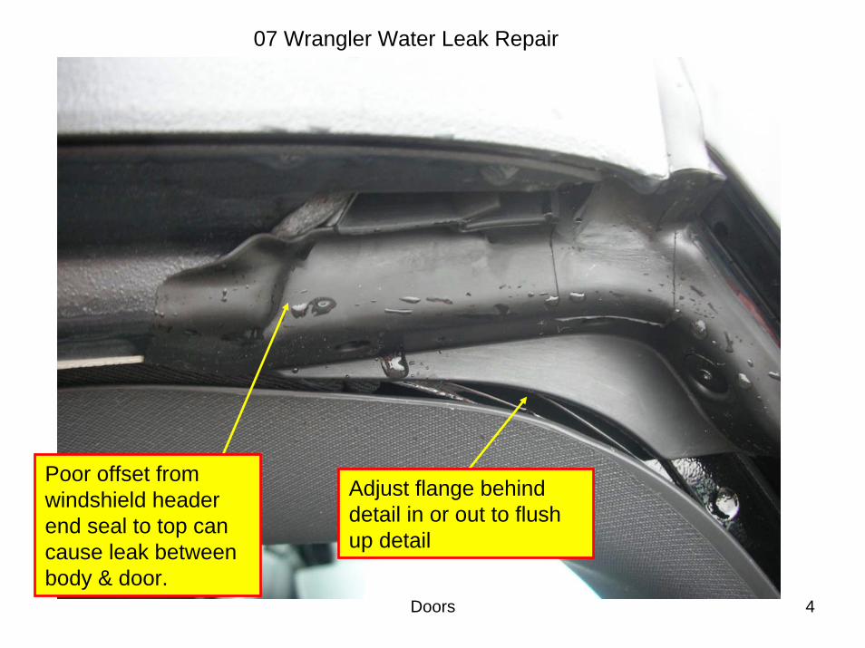
07 Wrangler Water Leak Repair
Poor offset from windshield header end seal to top can cause leak between body & door.
Adjust flange behind detail in or out to flush up detail
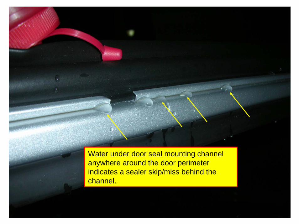
Doors 5
07 Wrangler Water Leak Repair
Water under door seal mounting channel anywhere around the door perimeter indicates a sealer skip/miss behind the channel.
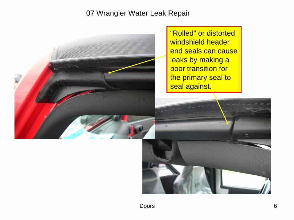
Doors 6
07 Wrangler Water Leak Repair
“Rolled” or distorted windshield header end seals can cause leaks by making a poor transition for the primary seal to seal against.
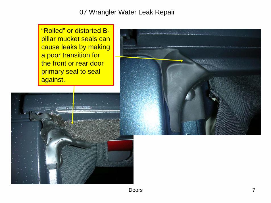
Doors 7
07 Wrangler Water Leak Repair
“Rolled” or distorted B-pillar mucket seals can cause leaks by making a poor transition for the front or rear door primary seal to seal against.
Doors 8
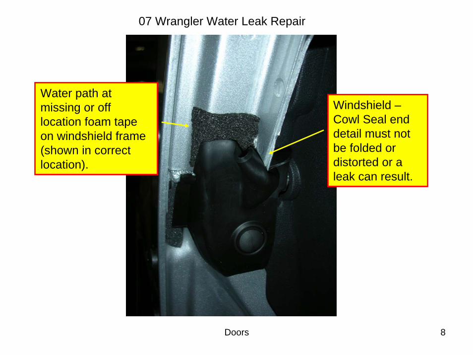
07 Wrangler Water Leak Repair
Water path at missing or off location foam tape on windshield frame (shown in correct location).
Windshield –Cowl Seal end detail must not be folded or distorted or a leak can result.
Doors 9
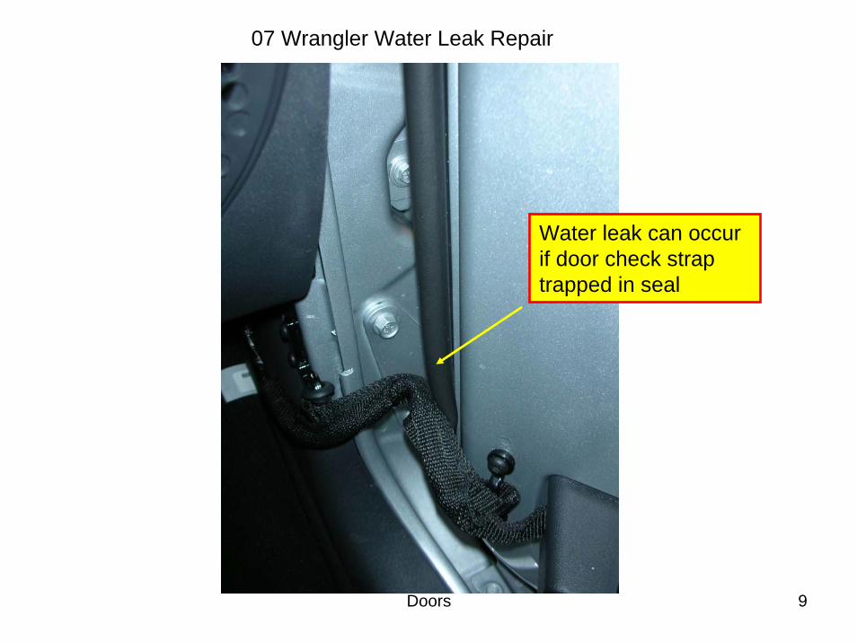
07 Wrangler Water Leak Repair
Water leak can occur if door check strap trapped in seal
Doors 10
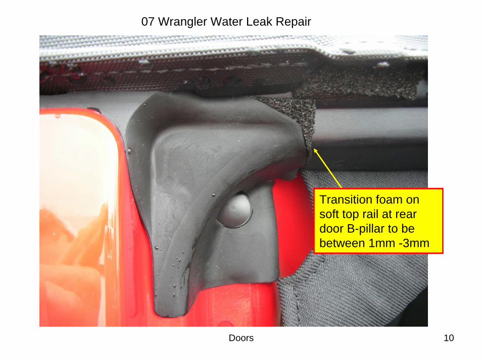
07 Wrangler Water Leak Repair
Transition foam on soft top rail at rear door B-pillar to be between 1mm -3mm
Doors 11
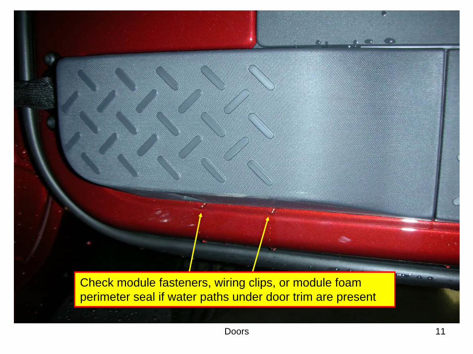
07 Wrangler Water Leak Repair
Check module fasteners, wiring clips, or module foam perimeter seal if water paths under door trim are present
This bulletin is supplied as technical information only and is not an authorization for repair. No part of this publication may be reproduced, stored in a retrieval system,or transmitted, in any form or by any means, electronic, mechanical, photocopying, or otherwise, without written permission of Chrysler LLC.
THIS BULLETIN SUPERSEDES TECHNICAL SERVICE BULLETIN 23-041-07, DATEDSEPTEMBER 29, 2007 WHICH SHOULD BE REMOVED FROM YOUR FILES. ALLREVISIONS ARE HIGHLIGHTED WITH **ASTERISKS** AND INCLUDE THE ADDITIONOF 2007 MODEL YEAR VEHICLES.
SUBJECT:Soft Top - Water Leak At Upper A-Pillar Door Seal To Door Rail Interface
OVERVIEW:This bulletin involves the addition of foam to eliminate a possible water leak at the upperA-Pillar.
MODELS:
**2007** - 2008 (JK) Wrangler
NOTE: This bulletin applies to vehicles equipped with a soft top (sales code GWK orVJ0) or with a dual top (sales code AEM).
SYMPTOM/CONDITION:On soft top equipped vehicles, water may leak past the door seal to door rail interface atthe upper A-Pillar.
DIAGNOSIS:1. Verify that the soft top is correctly installed and fastened correctly to the vehicle. The
soft top cover should be located and clamped in the correct sequence as described inthe Owners Manual.
2. Apply water to the affected area for about 3 - 5 minutes while inspecting the interior ofthe vehicle for possible water leaks and leak source.
3. If the source of the water leak is from the interface of the door seal to the door rail atthe upper A-Pillar, then perform the Repair Procedure.
PARTS REQUIRED:
Qty. Part No. Description
1 68026937AA Kit, Replacement Foam (Repair)
NUMBER: 23-002-08
GROUP: Body
DATE: January 15, 2008
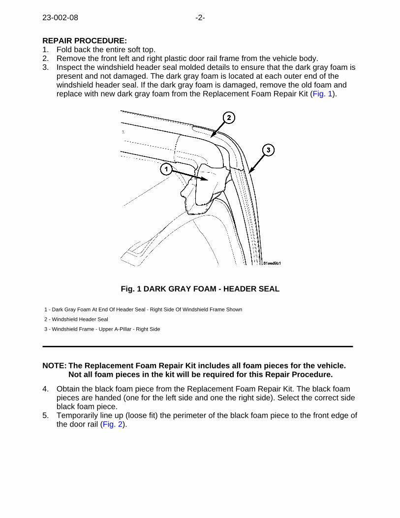
REPAIR PROCEDURE:1. Fold back the entire soft top.2. Remove the front left and right plastic door rail frame from the vehicle body.3. Inspect the windshield header seal molded details to ensure that the dark gray foam is
present and not damaged. The dark gray foam is located at each outer end of thewindshield header seal. If the dark gray foam is damaged, remove the old foam andreplace with new dark gray foam from the Replacement Foam Repair Kit (Fig. 1).
Fig. 1 DARK GRAY FOAM - HEADER SEAL
1 - Dark Gray Foam At End Of Header Seal - Right Side Of Windshield Frame Shown
2 - Windshield Header Seal
3 - Windshield Frame - Upper A-Pillar - Right Side
NOTE: The Replacement Foam Repair Kit includes all foam pieces for the vehicle.Not all foam pieces in the kit will be required for this Repair Procedure.
4. Obtain the black foam piece from the Replacement Foam Repair Kit. The black foampieces are handed (one for the left side and one the right side). Select the correct sideblack foam piece.
5. Temporarily line up (loose fit) the perimeter of the black foam piece to the front edge ofthe door rail (Fig. 2).
23-002-08 -2-
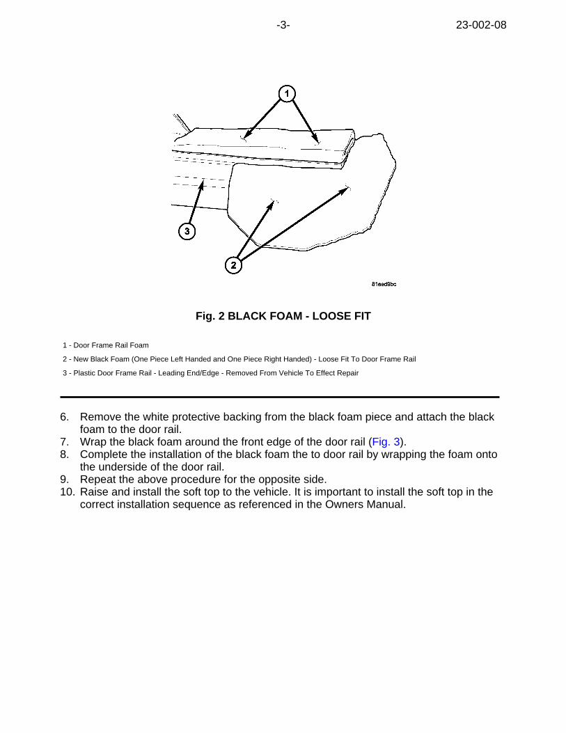
Fig. 2 BLACK FOAM - LOOSE FIT
1 - Door Frame Rail Foam
2 - New Black Foam (One Piece Left Handed and One Piece Right Handed) - Loose Fit To Door Frame Rail
3 - Plastic Door Frame Rail - Leading End/Edge - Removed From Vehicle To Effect Repair
6. Remove the white protective backing from the black foam piece and attach the blackfoam to the door rail.
7. Wrap the black foam around the front edge of the door rail (Fig. 3).8. Complete the installation of the black foam the to door rail by wrapping the foam onto
the underside of the door rail.9. Repeat the above procedure for the opposite side.10. Raise and install the soft top to the vehicle. It is important to install the soft top in the
correct installation sequence as referenced in the Owners Manual.
-3- 23-002-08
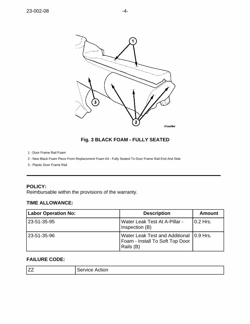
Fig. 3 BLACK FOAM - FULLY SEATED
1 - Door Frame Rail Foam
2 - New Black Foam Piece From Replacement Foam Kit - Fully Seated To Door Frame Rail End And Side
3 - Plastic Door Frame Rail
POLICY:Reimbursable within the provisions of the warranty.
TIME ALLOWANCE:
Labor Operation No: Description Amount
23-51-35-95 Water Leak Test At A-Pillar -Inspection (B)
0.2 Hrs.
23-51-35-96 Water Leak Test and AdditionalFoam - Install To Soft Top DoorRails (B)
0.9 Hrs.
FAILURE CODE:
ZZ Service Action
23-002-08 -4-
This bulletin is supplied as technical information only and is not an authorization for repair. No part of this publication may be reproduced, stored in a retrieval system,or transmitted, in any form or by any means, electronic, mechanical, photocopying, or otherwise, without written permission of Chrysler LLC.
THIS BULLETIN SUPERSEDES SERVICE BULLETINS 23-001-07 DATED JANUARY06, 2007 AND 23-050-07, DATED NOVEMBER 21, 2007. THIS IS A COMPLETEREVISION AND NO ASTERISKS HAVE BEEN USED TO HIGHLIGHT REVISIONS.
SUBJECT:Freedom Top - Center Seal - Water Leak In Area Of Center Console or Dash
OVERVIEW:This bulletin involves the select replacement of: the center seal and its associated foamtape, butyl adhesive, and weatherstrips.
MODELS:
2007 - 2008 (JK) Wrangler
NOTE: This bulletin applies to vehicles equipped with a Freedom Top - Modular HardTop
SYMPTOM/CONDITION:On vehicles equipped with a Freedom Top a leak water may occur in the area of the hardtop removable (targa) panels. This bulletin will address water leaks due to the CENTERSEAL of the removable Freedom Top (targa) panel.
If the center seal is at fault, the customer may experience a water leak in one of thefollowing areas:
a. On to the center console
b. On to the center section of the instrument panel
c. From the Freedom panel knob (dial) fasteners
d. At the sports bar cloth covering inboard of the B-Pillar
e. On to the front seat cushion or seat back
Water leaks may occur in other areas of the vehicle body that interface with the FreedomTop panels. These other areas may include: the A-Pillar, the B-Pillar, or the Door. Waterleaks in these areas are addressed in other Service Bulletins. Refer to those ServiceBulletins as necessary.
NUMBER: 23-020-08
GROUP: Body
DATE: June 20, 2008
DIAGNOSIS:1. Prior to performing this Service Bulletin refer to additional supporting material
found in DealerCONNECT and TechCONNECT. At DealerCONNECT select: eFiles> Service (at left side of page) > Star Center > Misc Documents.
2. Determine the vehicle build date. Vehicles built on or before December 17, 2007(MDH 1217XX) will require the windshield header latch on each panel be replaced withthe latest level latch.
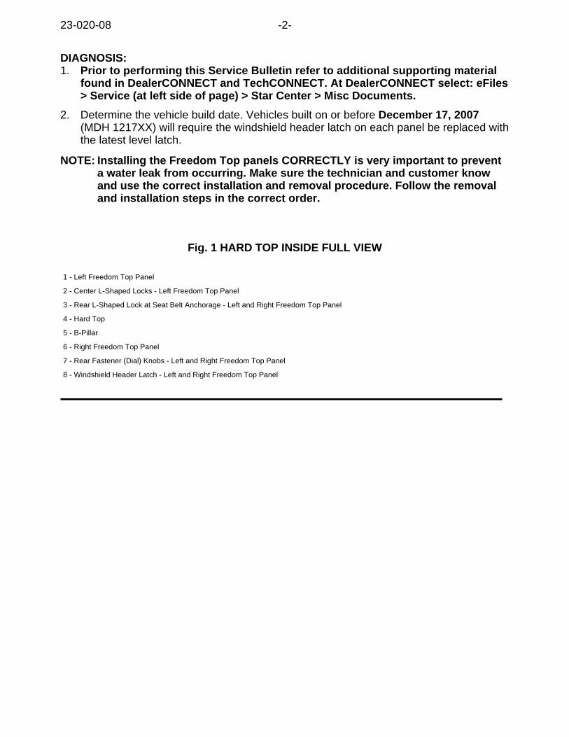
NOTE: Installing the Freedom Top panels CORRECTLY is very important to preventa water leak from occurring. Make sure the technician and customer knowand use the correct installation and removal procedure. Follow the removaland installation steps in the correct order.
Fig. 1 HARD TOP INSIDE FULL VIEW
1 - Left Freedom Top Panel
2 - Center L-Shaped Locks - Left Freedom Top Panel
3 - Rear L-Shaped Lock at Seat Belt Anchorage - Left and Right Freedom Top Panel
4 - Hard Top
5 - B-Pillar
6 - Right Freedom Top Panel
7 - Rear Fastener (Dial) Knobs - Left and Right Freedom Top Panel
8 - Windshield Header Latch - Left and Right Freedom Top Panel
23-020-08 -2-
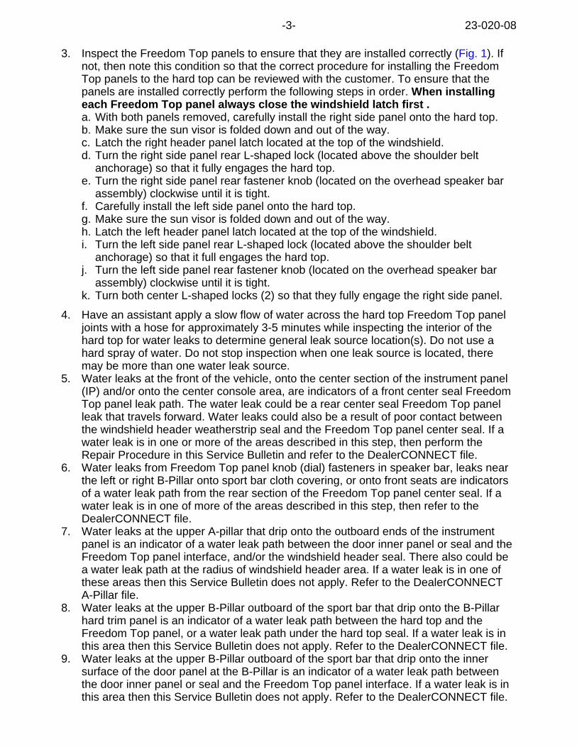
3. Inspect the Freedom Top panels to ensure that they are installed correctly (Fig. 1). Ifnot, then note this condition so that the correct procedure for installing the FreedomTop panels to the hard top can be reviewed with the customer. To ensure that thepanels are installed correctly perform the following steps in order. When installingeach Freedom Top panel always close the windshield latch first .a. With both panels removed, carefully install the right side panel onto the hard top.b. Make sure the sun visor is folded down and out of the way.c. Latch the right header panel latch located at the top of the windshield.d. Turn the right side panel rear L-shaped lock (located above the shoulder belt
anchorage) so that it fully engages the hard top.e. Turn the right side panel rear fastener knob (located on the overhead speaker bar
assembly) clockwise until it is tight.f. Carefully install the left side panel onto the hard top.g. Make sure the sun visor is folded down and out of the way.h. Latch the left header panel latch located at the top of the windshield.i. Turn the left side panel rear L-shaped lock (located above the shoulder belt
anchorage) so that it full engages the hard top.j. Turn the left side panel rear fastener knob (located on the overhead speaker bar
assembly) clockwise until it is tight.k. Turn both center L-shaped locks (2) so that they fully engage the right side panel.
4. Have an assistant apply a slow flow of water across the hard top Freedom Top paneljoints with a hose for approximately 3-5 minutes while inspecting the interior of thehard top for water leaks to determine general leak source location(s). Do not use ahard spray of water. Do not stop inspection when one leak source is located, theremay be more than one water leak source.
5. Water leaks at the front of the vehicle, onto the center section of the instrument panel(IP) and/or onto the center console area, are indicators of a front center seal FreedomTop panel leak path. The water leak could be a rear center seal Freedom Top panelleak that travels forward. Water leaks could also be a result of poor contact betweenthe windshield header weatherstrip seal and the Freedom Top panel center seal. If awater leak is in one or more of the areas described in this step, then perform theRepair Procedure in this Service Bulletin and refer to the DealerCONNECT file.
6. Water leaks from Freedom Top panel knob (dial) fasteners in speaker bar, leaks nearthe left or right B-Pillar onto sport bar cloth covering, or onto front seats are indicatorsof a water leak path from the rear section of the Freedom Top panel center seal. If awater leak is in one of more of the areas described in this step, then refer to theDealerCONNECT file.
7. Water leaks at the upper A-pillar that drip onto the outboard ends of the instrumentpanel is an indicator of a water leak path between the door inner panel or seal and theFreedom Top panel interface, and/or the windshield header seal. There also could bea water leak path at the radius of windshield header area. If a water leak is in one ofthese areas then this Service Bulletin does not apply. Refer to the DealerCONNECTA-Pillar file.
8. Water leaks at the upper B-Pillar outboard of the sport bar that drip onto the B-Pillarhard trim panel is an indicator of a water leak path between the hard top and theFreedom Top panel, or a water leak path under the hard top seal. If a water leak is inthis area then this Service Bulletin does not apply. Refer to the DealerCONNECT file.
9. Water leaks at the upper B-Pillar outboard of the sport bar that drip onto the innersurface of the door panel at the B-Pillar is an indicator of a water leak path betweenthe door inner panel or seal and the Freedom Top panel interface. If a water leak is inthis area then this Service Bulletin does not apply. Refer to the DealerCONNECT file.
-3- 23-020-08
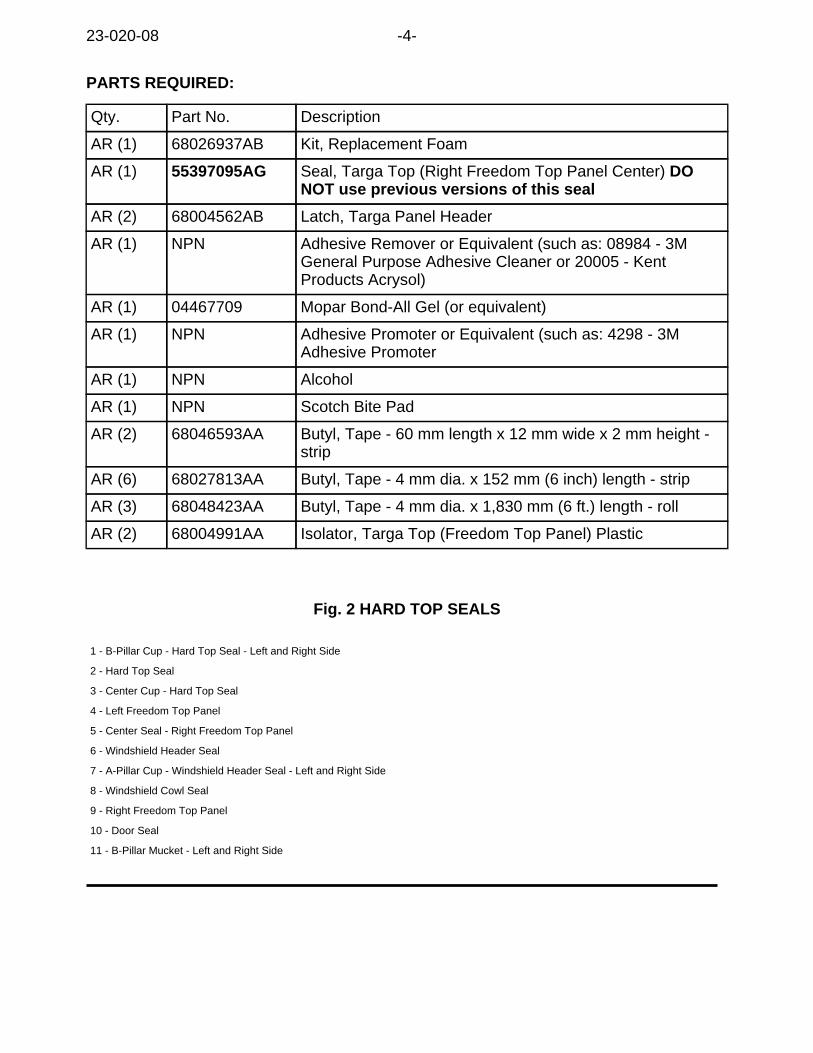
PARTS REQUIRED:
Qty. Part No. Description
AR (1) 68026937AB Kit, Replacement Foam
AR (1) 55397095AG Seal, Targa Top (Right Freedom Top Panel Center) DONOT use previous versions of this seal
AR (2) 68004562AB Latch, Targa Panel Header
AR (1) NPN Adhesive Remover or Equivalent (such as: 08984 - 3MGeneral Purpose Adhesive Cleaner or 20005 - KentProducts Acrysol)
AR (1) 04467709 Mopar Bond-All Gel (or equivalent)
AR (1) NPN Adhesive Promoter or Equivalent (such as: 4298 - 3MAdhesive Promoter
AR (1) NPN Alcohol
AR (1) NPN Scotch Bite Pad
AR (2) 68046593AA Butyl, Tape - 60 mm length x 12 mm wide x 2 mm height -strip
AR (6) 68027813AA Butyl, Tape - 4 mm dia. x 152 mm (6 inch) length - strip
AR (3) 68048423AA Butyl, Tape - 4 mm dia. x 1,830 mm (6 ft.) length - roll
AR (2) 68004991AA Isolator, Targa Top (Freedom Top Panel) Plastic
Fig. 2 HARD TOP SEALS
1 - B-Pillar Cup - Hard Top Seal - Left and Right Side
2 - Hard Top Seal
3 - Center Cup - Hard Top Seal
4 - Left Freedom Top Panel
5 - Center Seal - Right Freedom Top Panel
6 - Windshield Header Seal
7 - A-Pillar Cup - Windshield Header Seal - Left and Right Side
8 - Windshield Cowl Seal
9 - Right Freedom Top Panel
10 - Door Seal
11 - B-Pillar Mucket - Left and Right Side
23-020-08 -4-
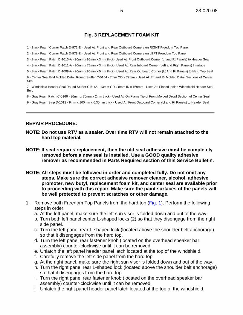
Fig. 3 REPLACEMENT FOAM KIT
1 - Black Foam Corner Patch D-972-E - Used At: Front and Rear Outboard Corners on RIGHT Freedom Top Panel
2 - Black Foam Corner Patch D-973-E - Used At: Front and Rear Outboard Corners on LEFT Freedom Top Panel
3 - Black Foam Patch D-1010-A - 30mm x 95mm x 3mm thick -Used At: Front Outboard Corner (Lt and Rt Panels) to Header Seal
4 - Black Foam Patch D-1011-A - 30mm x 75mm x 3mm thick - Used At: Rear Inboard Corner (Left and Right Panels) Interface
5 - Black Foam Patch D-1009-A - 20mm x 95mm x 5mm thick - Used At: Rear Outboard Corner (Lt And Rt Panels) to Hard Top Seal
6 - Center Seal End Molded Detail Round Stuffer C-5164 - 7mm OD x 72mm - Used At: Frt and Rr Molded Detail Sections of CenterSeal
7 - Windshield Header Seal Round Stuffer C-5165 - 13mm OD x 8mm ID x 160mm - Used At: Placed Inside Windshield Header SealBulb
8 - Gray Foam Patch C-5166 - 30mm x 75mm x 2mm thick - Used At: On Flame Tip of Front Molded Detail Section of Center Seal
9 - Gray Foam Strip D-1012 - 9mm x 100mm x 6.35mm thick - Used At: Front Outboard Corner (Lt and Rt Panels) to Header Seal
REPAIR PROCEDURE:
NOTE: Do not use RTV as a sealer. Over time RTV will not remain attached to thehard top material.
NOTE: If seal requires replacement, then the old seal adhesive must be completelyremoved before a new seal is installed. Use a GOOD quality adhesiveremover as recommended in Parts Required section of this Service Bulletin.
NOTE: All steps must be followed in order and completed fully. Do not omit anysteps. Make sure the correct adhesive remover cleaner, alcohol, adhesivepromoter, new butyl, replacement foam kit, and center seal are available priorto proceeding with this repair. Make sure the paint surfaces of the panels willbe well protected to prevent scratches or other damage.
1. Remove both Freedom Top Panels from the hard top (Fig. 1). Perform the followingsteps in order:a. At the left panel, make sure the left sun visor is folded down and out of the way.b. Turn both left panel center L-shaped locks (2) so that they disengage from the right
side panel.c. Turn the left panel rear L-shaped lock (located above the shoulder belt anchorage)
so that it disengages from the hard top.d. Turn the left panel rear fastener knob (located on the overhead speaker bar
assembly) counter-clockwise until it can be removed.e. Unlatch the left panel header panel latch located at the top of the windshield.f. Carefully remove the left side panel from the hard top.g. At the right panel, make sure the right sun visor is folded down and out of the way.h. Turn the right panel rear L-shaped lock (located above the shoulder belt anchorage)
so that it disengages from the hard top.i. Turn the right panel rear fastener knob (located on the overhead speaker bar
assembly) counter-clockwise until it can be removed.j. Unlatch the right panel header panel latch located at the top of the windshield.
-5- 23-020-08
k. Carefully remove the right side panel from the hard top.2. Set the Freedom Top panels on a well PROTECTED WORK SURFACE. Protect the
Freedom Top panel edges & top surface from damage.
NOTE: THE PAINTED TOP SURFACE OF THE FREEDOM TOP CAN EASILY BEDAMAGED IF CARE IS NOT TAKEN TO PROTECT IT.
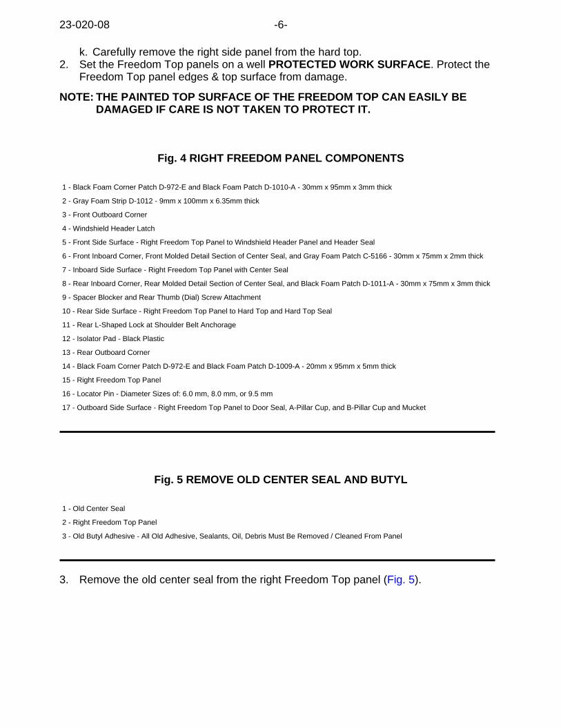
Fig. 4 RIGHT FREEDOM PANEL COMPONENTS
1 - Black Foam Corner Patch D-972-E and Black Foam Patch D-1010-A - 30mm x 95mm x 3mm thick
2 - Gray Foam Strip D-1012 - 9mm x 100mm x 6.35mm thick
3 - Front Outboard Corner
4 - Windshield Header Latch
5 - Front Side Surface - Right Freedom Top Panel to Windshield Header Panel and Header Seal
6 - Front Inboard Corner, Front Molded Detail Section of Center Seal, and Gray Foam Patch C-5166 - 30mm x 75mm x 2mm thick
7 - Inboard Side Surface - Right Freedom Top Panel with Center Seal
8 - Rear Inboard Corner, Rear Molded Detail Section of Center Seal, and Black Foam Patch D-1011-A - 30mm x 75mm x 3mm thick
9 - Spacer Blocker and Rear Thumb (Dial) Screw Attachment
10 - Rear Side Surface - Right Freedom Top Panel to Hard Top and Hard Top Seal
11 - Rear L-Shaped Lock at Shoulder Belt Anchorage
12 - Isolator Pad - Black Plastic
13 - Rear Outboard Corner
14 - Black Foam Corner Patch D-972-E and Black Foam Patch D-1009-A - 20mm x 95mm x 5mm thick
15 - Right Freedom Top Panel
16 - Locator Pin - Diameter Sizes of: 6.0 mm, 8.0 mm, or 9.5 mm
17 - Outboard Side Surface - Right Freedom Top Panel to Door Seal, A-Pillar Cup, and B-Pillar Cup and Mucket
Fig. 5 REMOVE OLD CENTER SEAL AND BUTYL
1 - Old Center Seal
2 - Right Freedom Top Panel
3 - Old Butyl Adhesive - All Old Adhesive, Sealants, Oil, Debris Must Be Removed / Cleaned From Panel
3. Remove the old center seal from the right Freedom Top panel (Fig. 5).
23-020-08 -6-
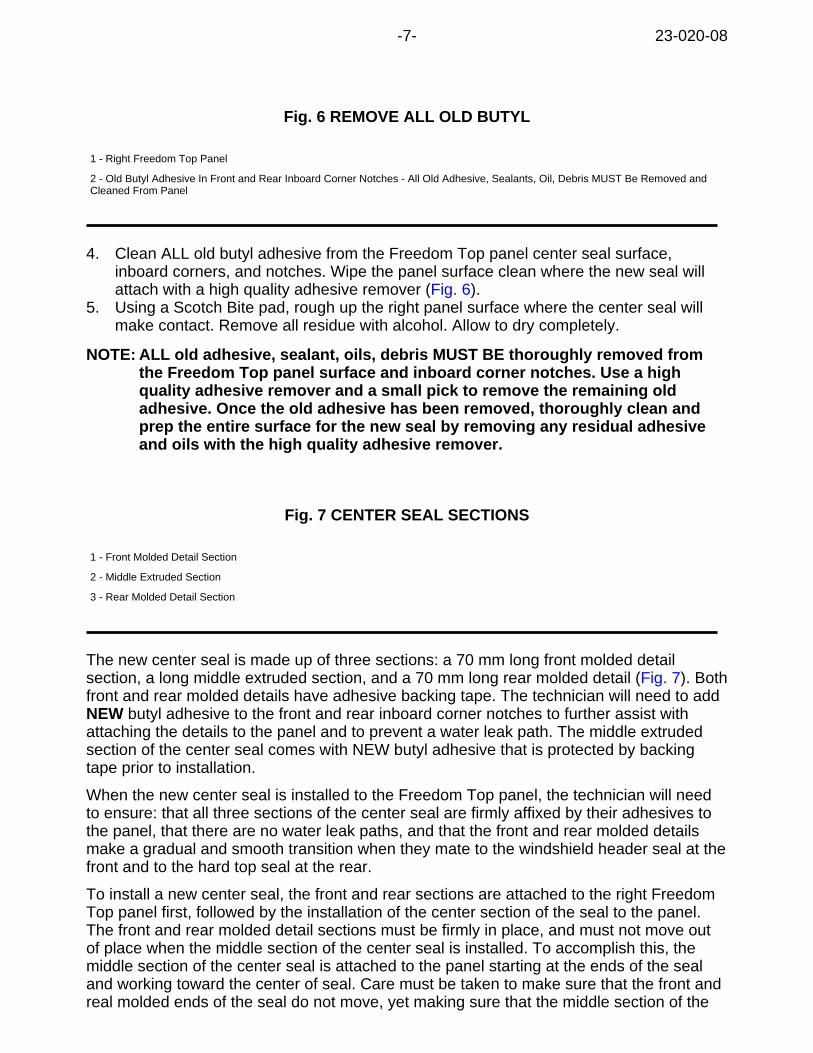
Fig. 6 REMOVE ALL OLD BUTYL
1 - Right Freedom Top Panel
2 - Old Butyl Adhesive In Front and Rear Inboard Corner Notches - All Old Adhesive, Sealants, Oil, Debris MUST Be Removed andCleaned From Panel
4. Clean ALL old butyl adhesive from the Freedom Top panel center seal surface,inboard corners, and notches. Wipe the panel surface clean where the new seal willattach with a high quality adhesive remover (Fig. 6).
5. Using a Scotch Bite pad, rough up the right panel surface where the center seal willmake contact. Remove all residue with alcohol. Allow to dry completely.
NOTE: ALL old adhesive, sealant, oils, debris MUST BE thoroughly removed fromthe Freedom Top panel surface and inboard corner notches. Use a highquality adhesive remover and a small pick to remove the remaining oldadhesive. Once the old adhesive has been removed, thoroughly clean andprep the entire surface for the new seal by removing any residual adhesiveand oils with the high quality adhesive remover.
Fig. 7 CENTER SEAL SECTIONS
1 - Front Molded Detail Section
2 - Middle Extruded Section
3 - Rear Molded Detail Section
The new center seal is made up of three sections: a 70 mm long front molded detailsection, a long middle extruded section, and a 70 mm long rear molded detail (Fig. 7). Bothfront and rear molded details have adhesive backing tape. The technician will need to addNEW butyl adhesive to the front and rear inboard corner notches to further assist withattaching the details to the panel and to prevent a water leak path. The middle extrudedsection of the center seal comes with NEW butyl adhesive that is protected by backingtape prior to installation.
When the new center seal is installed to the Freedom Top panel, the technician will needto ensure: that all three sections of the center seal are firmly affixed by their adhesives tothe panel, that there are no water leak paths, and that the front and rear molded detailsmake a gradual and smooth transition when they mate to the windshield header seal at thefront and to the hard top seal at the rear.
To install a new center seal, the front and rear sections are attached to the right FreedomTop panel first, followed by the installation of the center section of the seal to the panel.The front and rear molded detail sections must be firmly in place, and must not move outof place when the middle section of the center seal is installed. To accomplish this, themiddle section of the center seal is attached to the panel starting at the ends of the sealand working toward the center of seal. Care must be taken to make sure that the front andreal molded ends of the seal do not move, yet making sure that the middle section of the
-7- 23-020-08
seal is not bunched up at the center when it is installed.
Apply New Butyl Adhesive To Panel Front Inboard Corner:
6. On the right Freedom Top panel, locate the front inboard corner. Turn the rightFreedom Top panel over so that the inside surface of the panel is facing up (outsidesurface of panel is resting on the protected work surface).
7. At the front inner corner of the panel, loose fit (do not attach at this time) the frontmolded detail of the new center seal to the front inner corner. Note and mark wherethe front molded detail wraps at the intersecting edges of the front corner. This iswhere new butyl adhesive will need to be applied. DO NOT reuse any old butyladhesive.
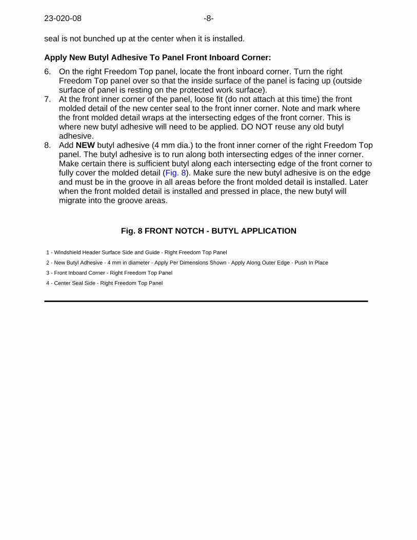
8. Add NEW butyl adhesive (4 mm dia.) to the front inner corner of the right Freedom Toppanel. The butyl adhesive is to run along both intersecting edges of the inner corner.Make certain there is sufficient butyl along each intersecting edge of the front corner tofully cover the molded detail (Fig. 8). Make sure the new butyl adhesive is on the edgeand must be in the groove in all areas before the front molded detail is installed. Laterwhen the front molded detail is installed and pressed in place, the new butyl willmigrate into the groove areas.
Fig. 8 FRONT NOTCH - BUTYL APPLICATION
1 - Windshield Header Surface Side and Guide - Right Freedom Top Panel
2 - New Butyl Adhesive - 4 mm in diameter - Apply Per Dimensions Shown - Apply Along Outer Edge - Push In Place
3 - Front Inboard Corner - Right Freedom Top Panel
4 - Center Seal Side - Right Freedom Top Panel
23-020-08 -8-
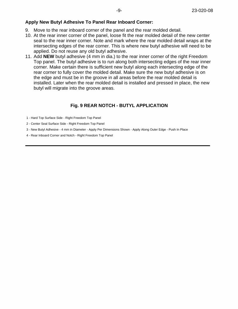
Apply New Butyl Adhesive To Panel Rear Inboard Corner:
9. Move to the rear inboard corner of the panel and the rear molded detail.10. At the rear inner corner of the panel, loose fit the rear molded detail of the new center
seal to the rear inner corner. Note and mark where the rear molded detail wraps at theintersecting edges of the rear corner. This is where new butyl adhesive will need to beapplied. Do not reuse any old butyl adhesive.
11. Add NEW butyl adhesive (4 mm in dia.) to the rear inner corner of the right FreedomTop panel. The butyl adhesive is to run along both intersecting edges of the rear innercorner. Make certain there is sufficient new butyl along each intersecting edge of therear corner to fully cover the molded detail. Make sure the new butyl adhesive is onthe edge and must be in the groove in all areas before the rear molded detail isinstalled. Later when the rear molded detail is installed and pressed in place, the newbutyl will migrate into the groove areas.
Fig. 9 REAR NOTCH - BUTYL APPLICATION
1 - Hard Top Surface Side - Right Freedom Top Panel
2 - Center Seal Surface Side - Right Freedom Top Panel
3 - New Butyl Adhesive - 4 mm in Diameter - Apply Per Dimensions Shown - Apply Along Outer Edge - Push In Place
4 - Rear Inboard Corner and Notch - Right Freedom Top Panel
-9- 23-020-08
Attach Front Molded Detail Section of the Center Seal:
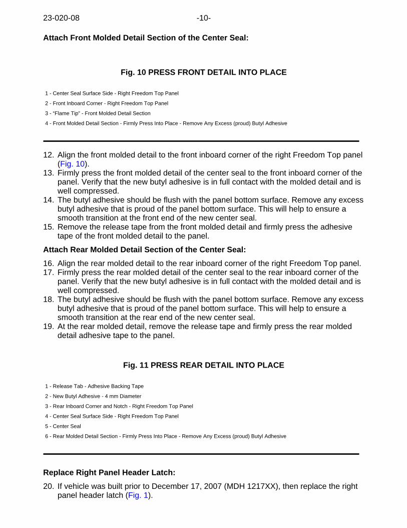
Fig. 10 PRESS FRONT DETAIL INTO PLACE
1 - Center Seal Surface Side - Right Freedom Top Panel
2 - Front Inboard Corner - Right Freedom Top Panel
3 - “Flame Tip” - Front Molded Detail Section
4 - Front Molded Detail Section - Firmly Press Into Place - Remove Any Excess (proud) Butyl Adhesive
12. Align the front molded detail to the front inboard corner of the right Freedom Top panel(Fig. 10).
13. Firmly press the front molded detail of the center seal to the front inboard corner of thepanel. Verify that the new butyl adhesive is in full contact with the molded detail and iswell compressed.
14. The butyl adhesive should be flush with the panel bottom surface. Remove any excessbutyl adhesive that is proud of the panel bottom surface. This will help to ensure asmooth transition at the front end of the new center seal.
15. Remove the release tape from the front molded detail and firmly press the adhesivetape of the front molded detail to the panel.
Attach Rear Molded Detail Section of the Center Seal:
16. Align the rear molded detail to the rear inboard corner of the right Freedom Top panel.17. Firmly press the rear molded detail of the center seal to the rear inboard corner of the
panel. Verify that the new butyl adhesive is in full contact with the molded detail and iswell compressed.
18. The butyl adhesive should be flush with the panel bottom surface. Remove any excessbutyl adhesive that is proud of the panel bottom surface. This will help to ensure asmooth transition at the rear end of the new center seal.
19. At the rear molded detail, remove the release tape and firmly press the rear moldeddetail adhesive tape to the panel.
Fig. 11 PRESS REAR DETAIL INTO PLACE
1 - Release Tab - Adhesive Backing Tape
2 - New Butyl Adhesive - 4 mm Diameter
3 - Rear Inboard Corner and Notch - Right Freedom Top Panel
4 - Center Seal Surface Side - Right Freedom Top Panel
5 - Center Seal
6 - Rear Molded Detail Section - Firmly Press Into Place - Remove Any Excess (proud) Butyl Adhesive
Replace Right Panel Header Latch:
20. If vehicle was built prior to December 17, 2007 (MDH 1217XX), then replace the rightpanel header latch (Fig. 1).
23-020-08 -10-
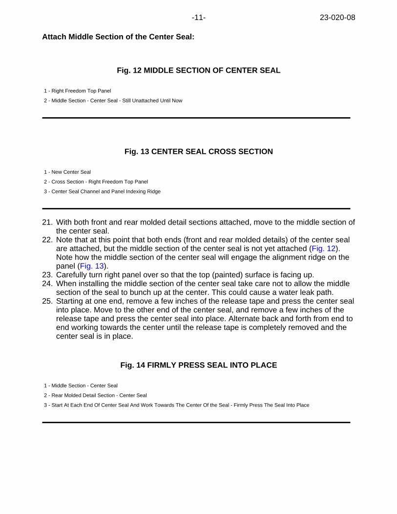
Attach Middle Section of the Center Seal:
Fig. 12 MIDDLE SECTION OF CENTER SEAL
1 - Right Freedom Top Panel
2 - Middle Section - Center Seal - Still Unattached Until Now
Fig. 13 CENTER SEAL CROSS SECTION
1 - New Center Seal
2 - Cross Section - Right Freedom Top Panel
3 - Center Seal Channel and Panel Indexing Ridge
21. With both front and rear molded detail sections attached, move to the middle section ofthe center seal.
22. Note that at this point that both ends (front and rear molded details) of the center sealare attached, but the middle section of the center seal is not yet attached (Fig. 12).Note how the middle section of the center seal will engage the alignment ridge on thepanel (Fig. 13).
23. Carefully turn right panel over so that the top (painted) surface is facing up.24. When installing the middle section of the center seal take care not to allow the middle
section of the seal to bunch up at the center. This could cause a water leak path.25. Starting at one end, remove a few inches of the release tape and press the center seal
into place. Move to the other end of the center seal, and remove a few inches of therelease tape and press the center seal into place. Alternate back and forth from end toend working towards the center until the release tape is completely removed and thecenter seal is in place.
Fig. 14 FIRMLY PRESS SEAL INTO PLACE
1 - Middle Section - Center Seal
2 - Rear Molded Detail Section - Center Seal
3 - Start At Each End Of Center Seal And Work Towards The Center Of the Seal - Firmly Press The Seal Into Place
-11- 23-020-08
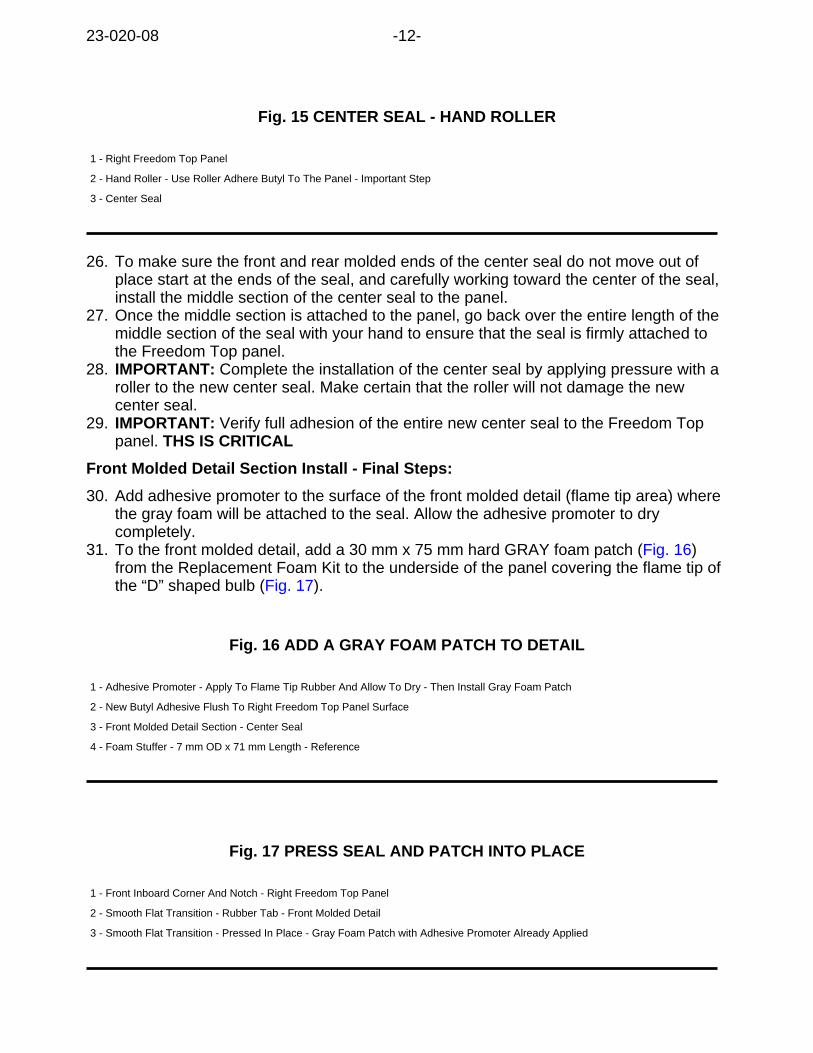
Fig. 15 CENTER SEAL - HAND ROLLER
1 - Right Freedom Top Panel
2 - Hand Roller - Use Roller Adhere Butyl To The Panel - Important Step
3 - Center Seal
26. To make sure the front and rear molded ends of the center seal do not move out ofplace start at the ends of the seal, and carefully working toward the center of the seal,install the middle section of the center seal to the panel.
27. Once the middle section is attached to the panel, go back over the entire length of themiddle section of the seal with your hand to ensure that the seal is firmly attached tothe Freedom Top panel.
28. IMPORTANT: Complete the installation of the center seal by applying pressure with aroller to the new center seal. Make certain that the roller will not damage the newcenter seal.
29. IMPORTANT: Verify full adhesion of the entire new center seal to the Freedom Toppanel. THS IS CRITICAL
Front Molded Detail Section Install - Final Steps:
30. Add adhesive promoter to the surface of the front molded detail (flame tip area) wherethe gray foam will be attached to the seal. Allow the adhesive promoter to drycompletely.
31. To the front molded detail, add a 30 mm x 75 mm hard GRAY foam patch (Fig. 16)from the Replacement Foam Kit to the underside of the panel covering the flame tip ofthe “D” shaped bulb (Fig. 17).
Fig. 16 ADD A GRAY FOAM PATCH TO DETAIL
1 - Adhesive Promoter - Apply To Flame Tip Rubber And Allow To Dry - Then Install Gray Foam Patch
2 - New Butyl Adhesive Flush To Right Freedom Top Panel Surface
3 - Front Molded Detail Section - Center Seal
4 - Foam Stuffer - 7 mm OD x 71 mm Length - Reference
Fig. 17 PRESS SEAL AND PATCH INTO PLACE
1 - Front Inboard Corner And Notch - Right Freedom Top Panel
2 - Smooth Flat Transition - Rubber Tab - Front Molded Detail
3 - Smooth Flat Transition - Pressed In Place - Gray Foam Patch with Adhesive Promoter Already Applied
23-020-08 -12-
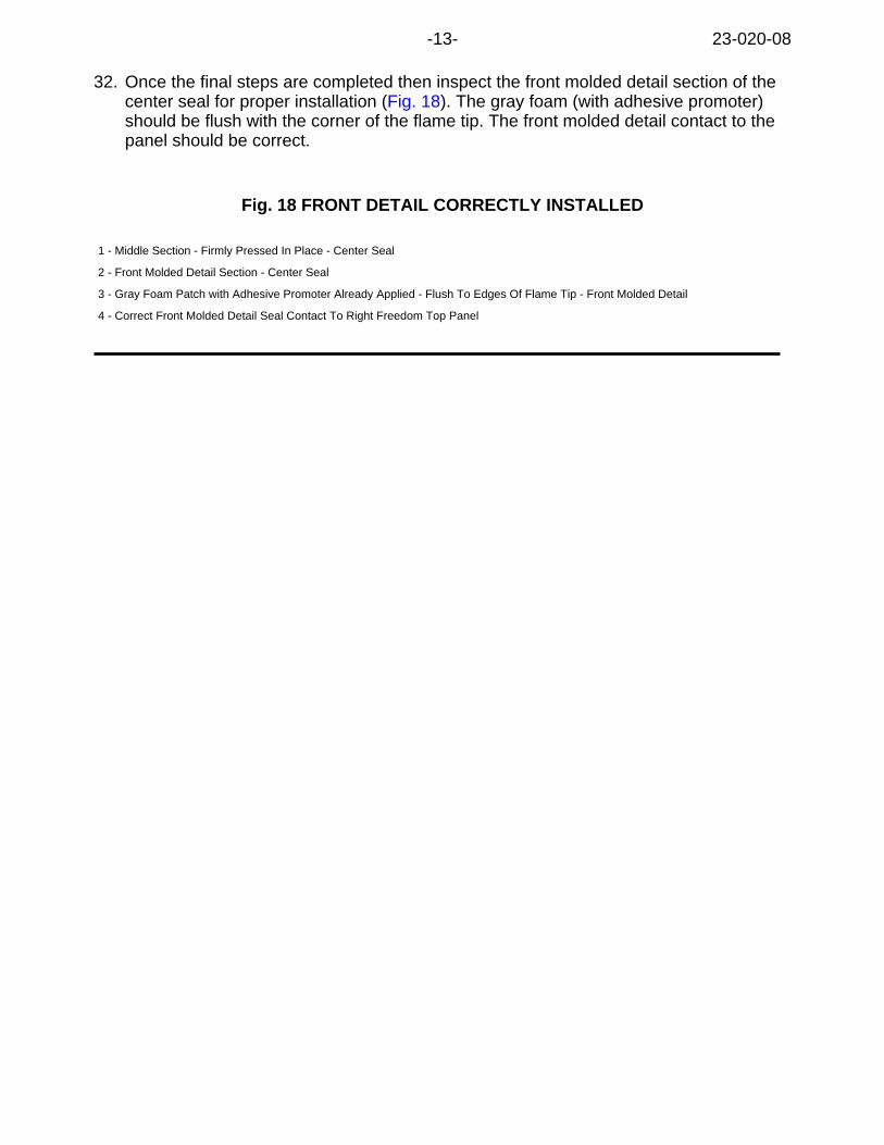
32. Once the final steps are completed then inspect the front molded detail section of thecenter seal for proper installation (Fig. 18). The gray foam (with adhesive promoter)should be flush with the corner of the flame tip. The front molded detail contact to thepanel should be correct.
Fig. 18 FRONT DETAIL CORRECTLY INSTALLED
1 - Middle Section - Firmly Pressed In Place - Center Seal
2 - Front Molded Detail Section - Center Seal
3 - Gray Foam Patch with Adhesive Promoter Already Applied - Flush To Edges Of Flame Tip - Front Molded Detail
4 - Correct Front Molded Detail Seal Contact To Right Freedom Top Panel
-13- 23-020-08
Rear Molded Detail Section Install - Final Steps:
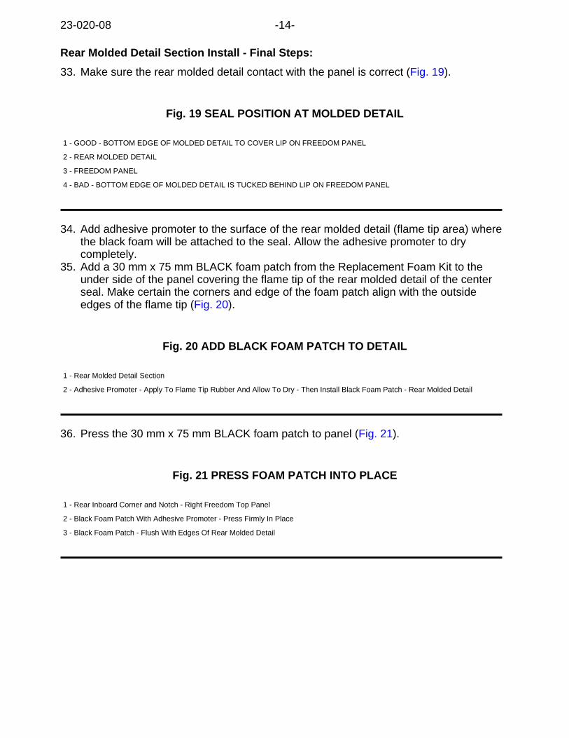
33. Make sure the rear molded detail contact with the panel is correct (Fig. 19).
Fig. 19 SEAL POSITION AT MOLDED DETAIL
1 - GOOD - BOTTOM EDGE OF MOLDED DETAIL TO COVER LIP ON FREEDOM PANEL
2 - REAR MOLDED DETAIL
3 - FREEDOM PANEL
4 - BAD - BOTTOM EDGE OF MOLDED DETAIL IS TUCKED BEHIND LIP ON FREEDOM PANEL
34. Add adhesive promoter to the surface of the rear molded detail (flame tip area) wherethe black foam will be attached to the seal. Allow the adhesive promoter to drycompletely.
35. Add a 30 mm x 75 mm BLACK foam patch from the Replacement Foam Kit to theunder side of the panel covering the flame tip of the rear molded detail of the centerseal. Make certain the corners and edge of the foam patch align with the outsideedges of the flame tip (Fig. 20).
Fig. 20 ADD BLACK FOAM PATCH TO DETAIL
1 - Rear Molded Detail Section
2 - Adhesive Promoter - Apply To Flame Tip Rubber And Allow To Dry - Then Install Black Foam Patch - Rear Molded Detail
36. Press the 30 mm x 75 mm BLACK foam patch to panel (Fig. 21).
Fig. 21 PRESS FOAM PATCH INTO PLACE
1 - Rear Inboard Corner and Notch - Right Freedom Top Panel
2 - Black Foam Patch With Adhesive Promoter - Press Firmly In Place
3 - Black Foam Patch - Flush With Edges Of Rear Molded Detail
23-020-08 -14-
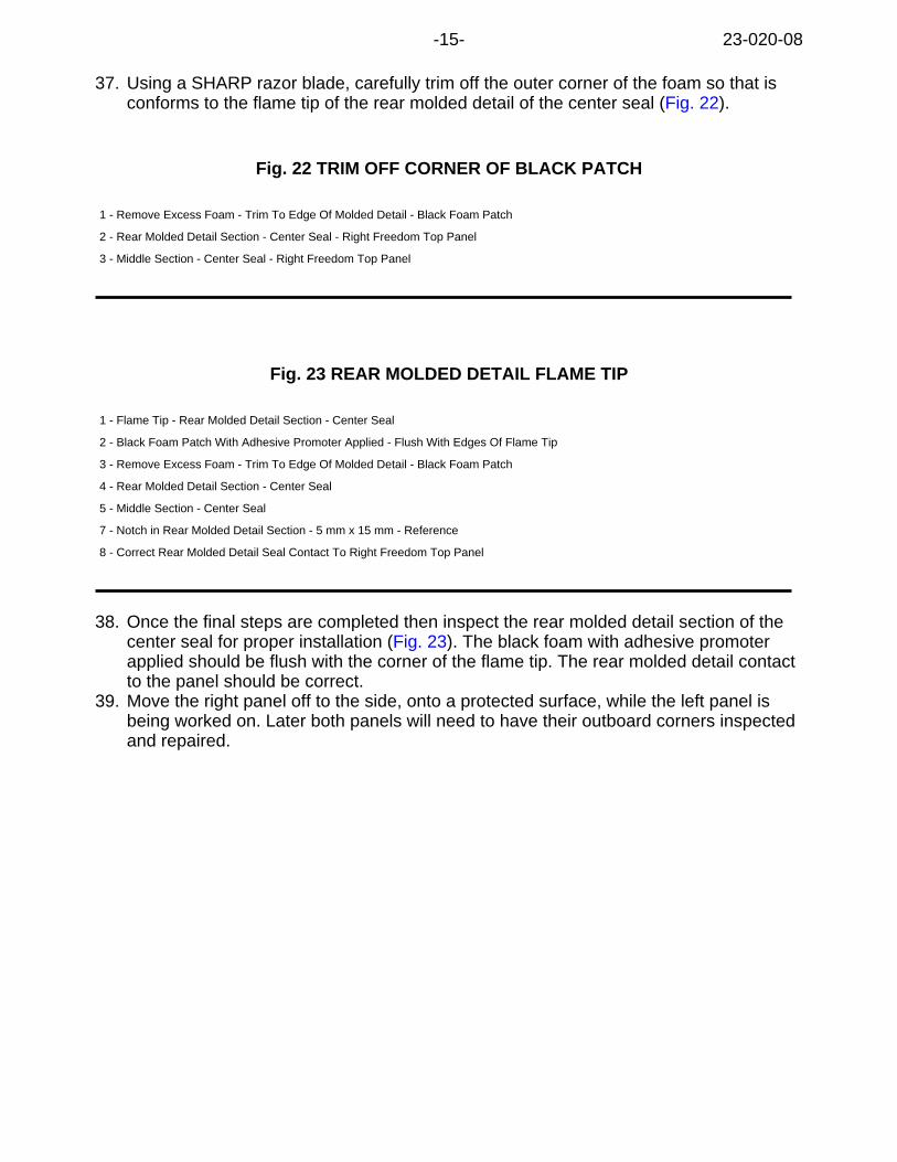
37. Using a SHARP razor blade, carefully trim off the outer corner of the foam so that isconforms to the flame tip of the rear molded detail of the center seal (Fig. 22).
Fig. 22 TRIM OFF CORNER OF BLACK PATCH
1 - Remove Excess Foam - Trim To Edge Of Molded Detail - Black Foam Patch
2 - Rear Molded Detail Section - Center Seal - Right Freedom Top Panel
3 - Middle Section - Center Seal - Right Freedom Top Panel
Fig. 23 REAR MOLDED DETAIL FLAME TIP
1 - Flame Tip - Rear Molded Detail Section - Center Seal
2 - Black Foam Patch With Adhesive Promoter Applied - Flush With Edges Of Flame Tip
3 - Remove Excess Foam - Trim To Edge Of Molded Detail - Black Foam Patch
4 - Rear Molded Detail Section - Center Seal
5 - Middle Section - Center Seal
7 - Notch in Rear Molded Detail Section - 5 mm x 15 mm - Reference
8 - Correct Rear Molded Detail Seal Contact To Right Freedom Top Panel
38. Once the final steps are completed then inspect the rear molded detail section of thecenter seal for proper installation (Fig. 23). The black foam with adhesive promoterapplied should be flush with the corner of the flame tip. The rear molded detail contactto the panel should be correct.
39. Move the right panel off to the side, onto a protected surface, while the left panel isbeing worked on. Later both panels will need to have their outboard corners inspectedand repaired.
-15- 23-020-08
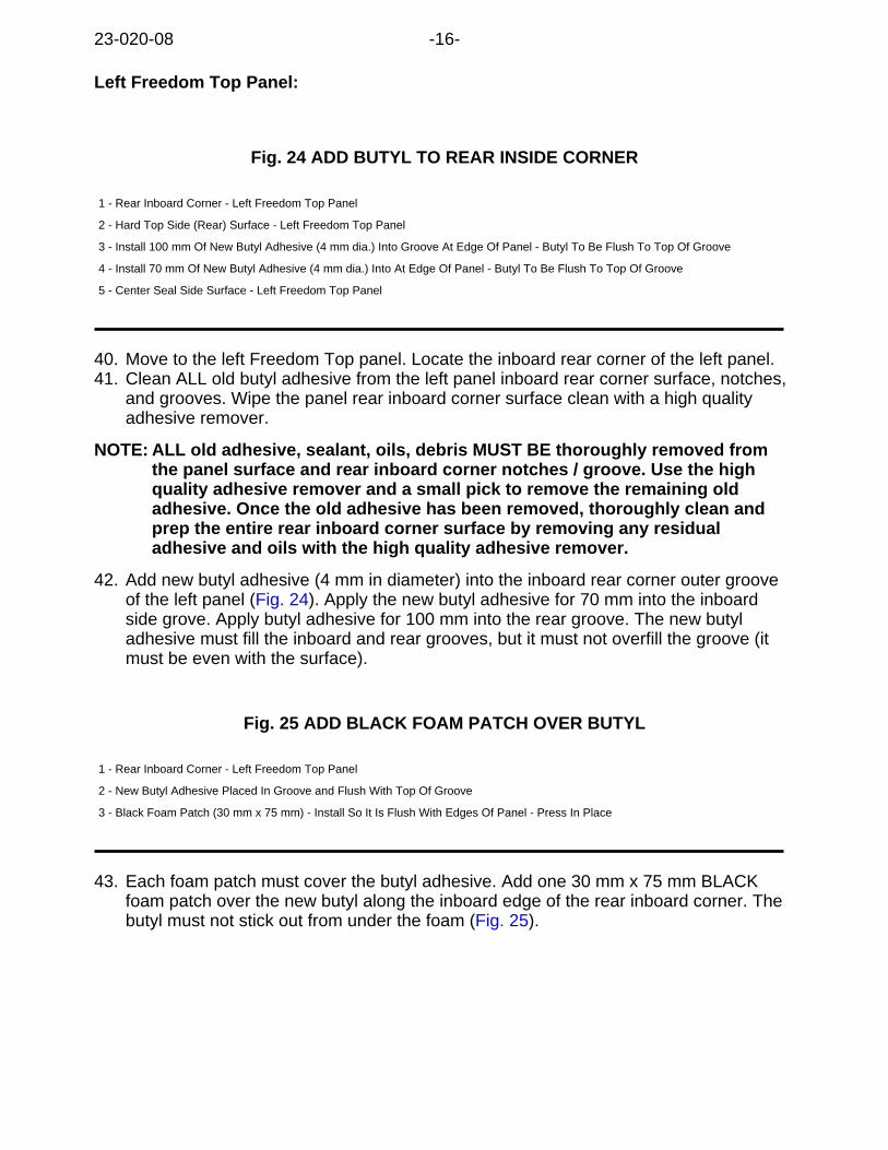
Left Freedom Top Panel:
Fig. 24 ADD BUTYL TO REAR INSIDE CORNER
1 - Rear Inboard Corner - Left Freedom Top Panel
2 - Hard Top Side (Rear) Surface - Left Freedom Top Panel
3 - Install 100 mm Of New Butyl Adhesive (4 mm dia.) Into Groove At Edge Of Panel - Butyl To Be Flush To Top Of Groove
4 - Install 70 mm Of New Butyl Adhesive (4 mm dia.) Into At Edge Of Panel - Butyl To Be Flush To Top Of Groove
5 - Center Seal Side Surface - Left Freedom Top Panel
40. Move to the left Freedom Top panel. Locate the inboard rear corner of the left panel.41. Clean ALL old butyl adhesive from the left panel inboard rear corner surface, notches,
and grooves. Wipe the panel rear inboard corner surface clean with a high qualityadhesive remover.
NOTE: ALL old adhesive, sealant, oils, debris MUST BE thoroughly removed fromthe panel surface and rear inboard corner notches / groove. Use the highquality adhesive remover and a small pick to remove the remaining oldadhesive. Once the old adhesive has been removed, thoroughly clean andprep the entire rear inboard corner surface by removing any residualadhesive and oils with the high quality adhesive remover.
42. Add new butyl adhesive (4 mm in diameter) into the inboard rear corner outer grooveof the left panel (Fig. 24). Apply the new butyl adhesive for 70 mm into the inboardside grove. Apply butyl adhesive for 100 mm into the rear groove. The new butyladhesive must fill the inboard and rear grooves, but it must not overfill the groove (itmust be even with the surface).
Fig. 25 ADD BLACK FOAM PATCH OVER BUTYL
1 - Rear Inboard Corner - Left Freedom Top Panel
2 - New Butyl Adhesive Placed In Groove and Flush With Top Of Groove
3 - Black Foam Patch (30 mm x 75 mm) - Install So It Is Flush With Edges Of Panel - Press In Place
43. Each foam patch must cover the butyl adhesive. Add one 30 mm x 75 mm BLACKfoam patch over the new butyl along the inboard edge of the rear inboard corner. Thebutyl must not stick out from under the foam (Fig. 25).
23-020-08 -16-

Fig. 26 FOAM PATCHES COVERING BUTYL
1 - Rear Inboard Corner - Left Freedom Top Panel
2 - Black Foam Patch (30 mm x 75 mm) - Install So It Is Flush With Edges Of Panel - Press In Place
3 - Black Foam Patch (30 mm x 75 mm) - Install So It Is Flush With Edges Of Panel - Press In Place
44. Each foam patch must cover the butyl adhesive. Add one 30 mm x 75 mm BLACKfoam patch over the new butyl along the rear edge of the rear inboard corner. Thebutyl must not stick out from under the foam (Fig. 26).
Replace Left Panel Header Latch:
45. If vehicle was built prior to December 17, 2007 (MDH 1217XX), then replace the leftpanel header latch (Fig. 1).
Outboard Corners - Both Freedom Top Panel:
Fig. 27 CHECK OUTSIDE CORNERS FOR FOAM
1 - Outboard Corner - Right or Left Freedom Top Panel - Rear Outboard Corner Shown
2 - Black Foam Corner Patch - Used At: Front and Rear Outboard Corners - D-972-E for RIGHT Panel and D-973-E for LEFT Panel
3 - Black Foam Patch D-1009-A - 20mm x 95mm x 5mm thick - Used At: Rear Outboard Corner (Lt And Rt Panels) to Hard Top Seal
4 - Isolator - Black Plastic
46. With the LEFT PANEL, locate the rear outboard corner of the panel.47. Note the location of the old foam patches. Remove the old foam patches from the rear
outboard corner of the left panel.48. Thoroughly clean all old adhesive residue from the rear outboard corner surface using
a high quality adhesive remover.49. Carefully install a new Black Foam Corner Patch to the rear outboard corner surface.
Ensure that no wrinkles are in the foam patch.50. Carefully install the Black Foam Patch (20mm x 95mm x 5mm) to the rear outboard
corner surface. Ensure that no wrinkles are in the foam patch.51. Move to the Front Outboard of the left panel.52. Note the location of the old black foam corner patch. Remove the old foam patch.53. Thoroughly clean all old adhesive residue from the front outboard corner surface using
a high quality adhesive remover.54. Carefully install a new Black Foam Corner Patch to the front outboard corner surface.
Ensure that no wrinkles are in the foam patch.55. Verify that the black plastic isolator is in place and not damaged. Replace the isolator if
damaged or missing.56. Verify that the alignment pin is in place and not damaged. Replace the alignment pin if
damaged or missing. Dependent upon when the hard top panel was made there aredifferent size alignment pins. Install the correct size diameter alignment pin.
57. Place the left panel to the side on a protected surface.58. Place the RIGHT PANEL top facing down on the protected work surface.
-17- 23-020-08
59. Repeat the above step in this section, Outboard Corners - Both Freedom Top Panel,to the front and rear outboard corners.
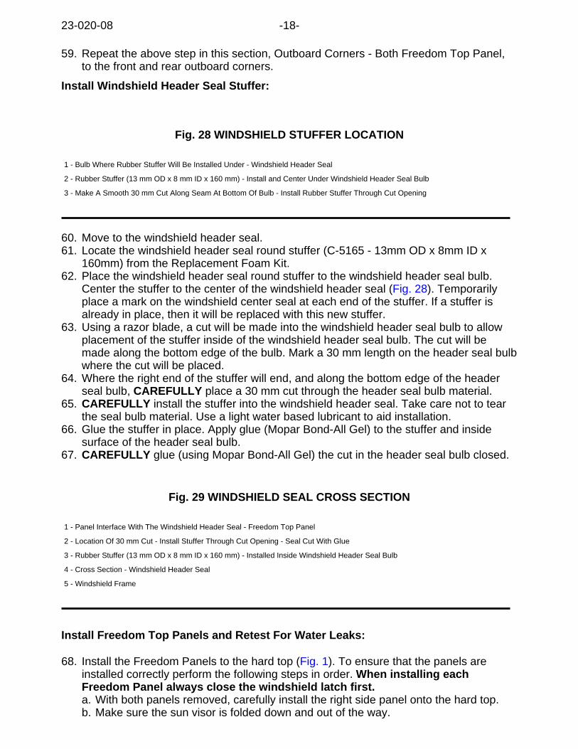
Install Windshield Header Seal Stuffer:
Fig. 28 WINDSHIELD STUFFER LOCATION
1 - Bulb Where Rubber Stuffer Will Be Installed Under - Windshield Header Seal
2 - Rubber Stuffer (13 mm OD x 8 mm ID x 160 mm) - Install and Center Under Windshield Header Seal Bulb
3 - Make A Smooth 30 mm Cut Along Seam At Bottom Of Bulb - Install Rubber Stuffer Through Cut Opening
60. Move to the windshield header seal.61. Locate the windshield header seal round stuffer (C-5165 - 13mm OD x 8mm ID x
160mm) from the Replacement Foam Kit.62. Place the windshield header seal round stuffer to the windshield header seal bulb.
Center the stuffer to the center of the windshield header seal (Fig. 28). Temporarilyplace a mark on the windshield center seal at each end of the stuffer. If a stuffer isalready in place, then it will be replaced with this new stuffer.
63. Using a razor blade, a cut will be made into the windshield header seal bulb to allowplacement of the stuffer inside of the windshield header seal bulb. The cut will bemade along the bottom edge of the bulb. Mark a 30 mm length on the header seal bulbwhere the cut will be placed.
64. Where the right end of the stuffer will end, and along the bottom edge of the headerseal bulb, CAREFULLY place a 30 mm cut through the header seal bulb material.
65. CAREFULLY install the stuffer into the windshield header seal. Take care not to tearthe seal bulb material. Use a light water based lubricant to aid installation.
66. Glue the stuffer in place. Apply glue (Mopar Bond-All Gel) to the stuffer and insidesurface of the header seal bulb.
67. CAREFULLY glue (using Mopar Bond-All Gel) the cut in the header seal bulb closed.
Fig. 29 WINDSHIELD SEAL CROSS SECTION
1 - Panel Interface With The Windshield Header Seal - Freedom Top Panel
2 - Location Of 30 mm Cut - Install Stuffer Through Cut Opening - Seal Cut With Glue
3 - Rubber Stuffer (13 mm OD x 8 mm ID x 160 mm) - Installed Inside Windshield Header Seal Bulb
4 - Cross Section - Windshield Header Seal
5 - Windshield Frame
Install Freedom Top Panels and Retest For Water Leaks:
68. Install the Freedom Panels to the hard top (Fig. 1). To ensure that the panels areinstalled correctly perform the following steps in order. When installing eachFreedom Panel always close the windshield latch first.a. With both panels removed, carefully install the right side panel onto the hard top.b. Make sure the sun visor is folded down and out of the way.
23-020-08 -18-
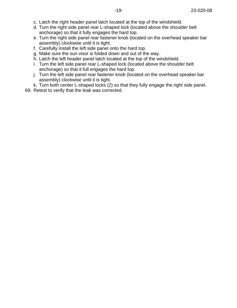
c. Latch the right header panel latch located at the top of the windshield.d. Turn the right side panel rear L-shaped lock (located above the shoulder belt
anchorage) so that it fully engages the hard top.e. Turn the right side panel rear fastener knob (located on the overhead speaker bar
assembly) clockwise until it is tight.f. Carefully install the left side panel onto the hard top.g. Make sure the sun visor is folded down and out of the way.h. Latch the left header panel latch located at the top of the windshield.i. Turn the left side panel rear L-shaped lock (located above the shoulder belt
anchorage) so that it full engages the hard top.j. Turn the left side panel rear fastener knob (located on the overhead speaker bar
assembly) clockwise until it is tight.k. Turn both center L-shaped locks (2) so that they fully engage the right side panel.
69. Retest to verify that the leak was corrected.
-19- 23-020-08
POLICY:Reimbursable within the provisions of the warranty.
TIME ALLOWANCE:
Labor Operation No: Description Amount
23-51-41-90 Center Seal - Modular Top Water Leak -Replace (B)
A/T Hrs.
FAILURE CODE:
ZZ Service Action
23-020-08 -20-
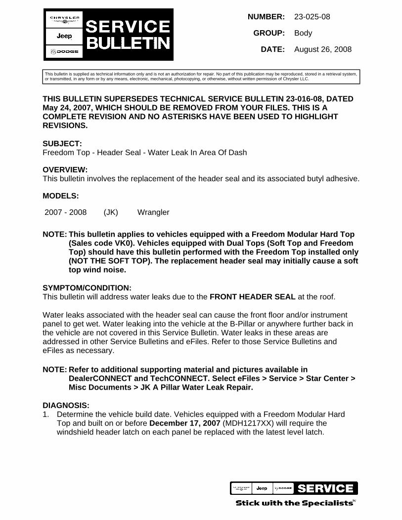
This bulletin is supplied as technical information only and is not an authorization for repair. No part of this publication may be reproduced, stored in a retrieval system,or transmitted, in any form or by any means, electronic, mechanical, photocopying, or otherwise, without written permission of Chrysler LLC.
THIS BULLETIN SUPERSEDES TECHNICAL SERVICE BULLETIN 23-016-08, DATEDMay 24, 2007, WHICH SHOULD BE REMOVED FROM YOUR FILES. THIS IS ACOMPLETE REVISION AND NO ASTERISKS HAVE BEEN USED TO HIGHLIGHTREVISIONS.
SUBJECT:Freedom Top - Header Seal - Water Leak In Area Of Dash
OVERVIEW:This bulletin involves the replacement of the header seal and its associated butyl adhesive.
MODELS:
2007 - 2008 (JK) Wrangler
NOTE: This bulletin applies to vehicles equipped with a Freedom Modular Hard Top(Sales code VK0). Vehicles equipped with Dual Tops (Soft Top and FreedomTop) should have this bulletin performed with the Freedom Top installed only(NOT THE SOFT TOP). The replacement header seal may initially cause a softtop wind noise.
SYMPTOM/CONDITION:This bulletin will address water leaks due to the FRONT HEADER SEAL at the roof.
Water leaks associated with the header seal can cause the front floor and/or instrumentpanel to get wet. Water leaking into the vehicle at the B-Pillar or anywhere further back inthe vehicle are not covered in this Service Bulletin. Water leaks in these areas areaddressed in other Service Bulletins and eFiles. Refer to those Service Bulletins andeFiles as necessary.
NOTE: Refer to additional supporting material and pictures available inDealerCONNECT and TechCONNECT. Select eFiles > Service > Star Center >Misc Documents > JK A Pillar Water Leak Repair.
DIAGNOSIS:1. Determine the vehicle build date. Vehicles equipped with a Freedom Modular Hard
Top and built on or before December 17, 2007 (MDH1217XX) will require thewindshield header latch on each panel be replaced with the latest level latch.
NUMBER: 23-025-08
GROUP: Body
DATE: August 26, 2008
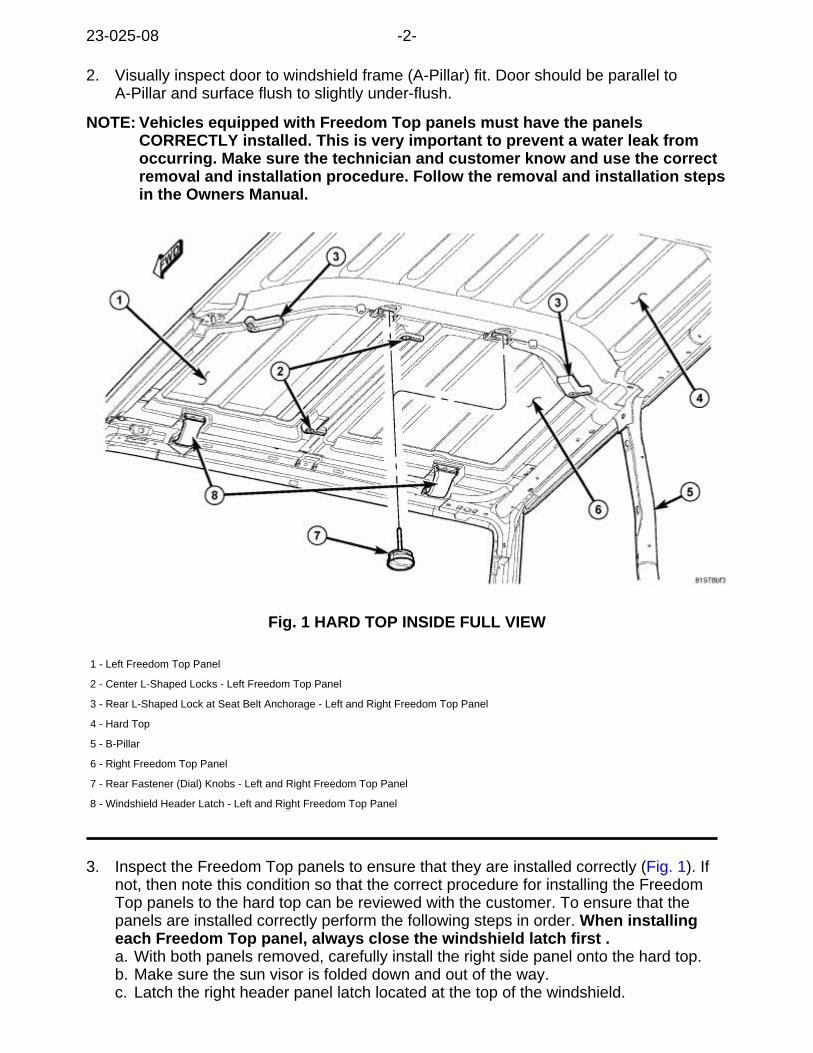
2. Visually inspect door to windshield frame (A-Pillar) fit. Door should be parallel toA-Pillar and surface flush to slightly under-flush.
NOTE: Vehicles equipped with Freedom Top panels must have the panelsCORRECTLY installed. This is very important to prevent a water leak fromoccurring. Make sure the technician and customer know and use the correctremoval and installation procedure. Follow the removal and installation stepsin the Owners Manual.
Fig. 1 HARD TOP INSIDE FULL VIEW
1 - Left Freedom Top Panel
2 - Center L-Shaped Locks - Left Freedom Top Panel
3 - Rear L-Shaped Lock at Seat Belt Anchorage - Left and Right Freedom Top Panel
4 - Hard Top
5 - B-Pillar
6 - Right Freedom Top Panel
7 - Rear Fastener (Dial) Knobs - Left and Right Freedom Top Panel
8 - Windshield Header Latch - Left and Right Freedom Top Panel
3. Inspect the Freedom Top panels to ensure that they are installed correctly (Fig. 1). Ifnot, then note this condition so that the correct procedure for installing the FreedomTop panels to the hard top can be reviewed with the customer. To ensure that thepanels are installed correctly perform the following steps in order. When installingeach Freedom Top panel, always close the windshield latch first .a. With both panels removed, carefully install the right side panel onto the hard top.b. Make sure the sun visor is folded down and out of the way.c. Latch the right header panel latch located at the top of the windshield.
23-025-08 -2-
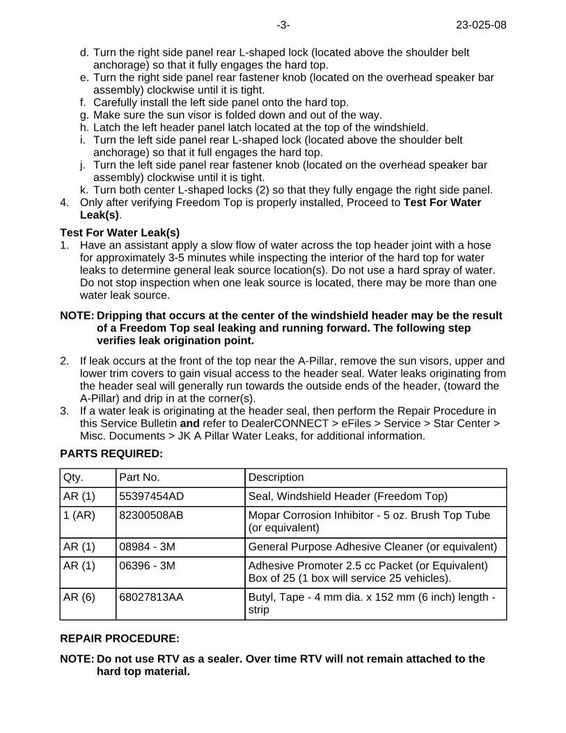
d. Turn the right side panel rear L-shaped lock (located above the shoulder beltanchorage) so that it fully engages the hard top.
e. Turn the right side panel rear fastener knob (located on the overhead speaker barassembly) clockwise until it is tight.
f. Carefully install the left side panel onto the hard top.g. Make sure the sun visor is folded down and out of the way.h. Latch the left header panel latch located at the top of the windshield.i. Turn the left side panel rear L-shaped lock (located above the shoulder belt
anchorage) so that it full engages the hard top.j. Turn the left side panel rear fastener knob (located on the overhead speaker bar
assembly) clockwise until it is tight.k. Turn both center L-shaped locks (2) so that they fully engage the right side panel.
4. Only after verifying Freedom Top is properly installed, Proceed to Test For WaterLeak(s).
Test For Water Leak(s)1. Have an assistant apply a slow flow of water across the top header joint with a hose
for approximately 3-5 minutes while inspecting the interior of the hard top for waterleaks to determine general leak source location(s). Do not use a hard spray of water.Do not stop inspection when one leak source is located, there may be more than onewater leak source.
NOTE: Dripping that occurs at the center of the windshield header may be the resultof a Freedom Top seal leaking and running forward. The following stepverifies leak origination point.
2. If leak occurs at the front of the top near the A-Pillar, remove the sun visors, upper andlower trim covers to gain visual access to the header seal. Water leaks originating fromthe header seal will generally run towards the outside ends of the header, (toward theA-Pillar) and drip in at the corner(s).
3. If a water leak is originating at the header seal, then perform the Repair Procedure inthis Service Bulletin and refer to DealerCONNECT > eFiles > Service > Star Center >Misc. Documents > JK A Pillar Water Leaks, for additional information.
PARTS REQUIRED:
Qty. Part No. Description
AR (1) 55397454AD Seal, Windshield Header (Freedom Top)
1 (AR) 82300508AB Mopar Corrosion Inhibitor - 5 oz. Brush Top Tube(or equivalent)
AR (1) 08984 - 3M General Purpose Adhesive Cleaner (or equivalent)
AR (1) 06396 - 3M Adhesive Promoter 2.5 cc Packet (or Equivalent)Box of 25 (1 box will service 25 vehicles).
AR (6) 68027813AA Butyl, Tape - 4 mm dia. x 152 mm (6 inch) length -strip
REPAIR PROCEDURE:
NOTE: Do not use RTV as a sealer. Over time RTV will not remain attached to thehard top material.
-3- 23-025-08
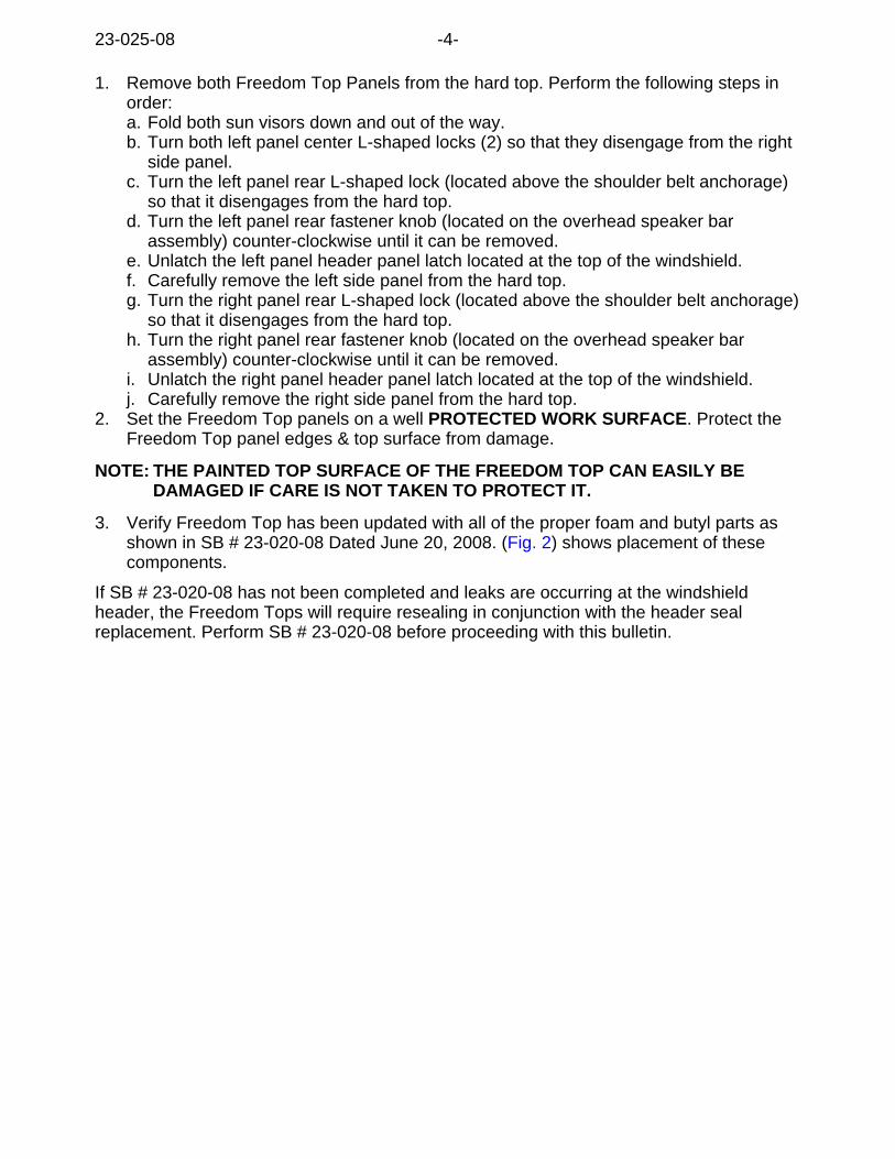
1. Remove both Freedom Top Panels from the hard top. Perform the following steps inorder:a. Fold both sun visors down and out of the way.b. Turn both left panel center L-shaped locks (2) so that they disengage from the right
side panel.c. Turn the left panel rear L-shaped lock (located above the shoulder belt anchorage)
so that it disengages from the hard top.d. Turn the left panel rear fastener knob (located on the overhead speaker bar
assembly) counter-clockwise until it can be removed.e. Unlatch the left panel header panel latch located at the top of the windshield.f. Carefully remove the left side panel from the hard top.g. Turn the right panel rear L-shaped lock (located above the shoulder belt anchorage)
so that it disengages from the hard top.h. Turn the right panel rear fastener knob (located on the overhead speaker bar
assembly) counter-clockwise until it can be removed.i. Unlatch the right panel header panel latch located at the top of the windshield.j. Carefully remove the right side panel from the hard top.
2. Set the Freedom Top panels on a well PROTECTED WORK SURFACE. Protect theFreedom Top panel edges & top surface from damage.
NOTE: THE PAINTED TOP SURFACE OF THE FREEDOM TOP CAN EASILY BEDAMAGED IF CARE IS NOT TAKEN TO PROTECT IT.
3. Verify Freedom Top has been updated with all of the proper foam and butyl parts asshown in SB # 23-020-08 Dated June 20, 2008. (Fig. 2) shows placement of thesecomponents.
If SB # 23-020-08 has not been completed and leaks are occurring at the windshieldheader, the Freedom Tops will require resealing in conjunction with the header sealreplacement. Perform SB # 23-020-08 before proceeding with this bulletin.
23-025-08 -4-
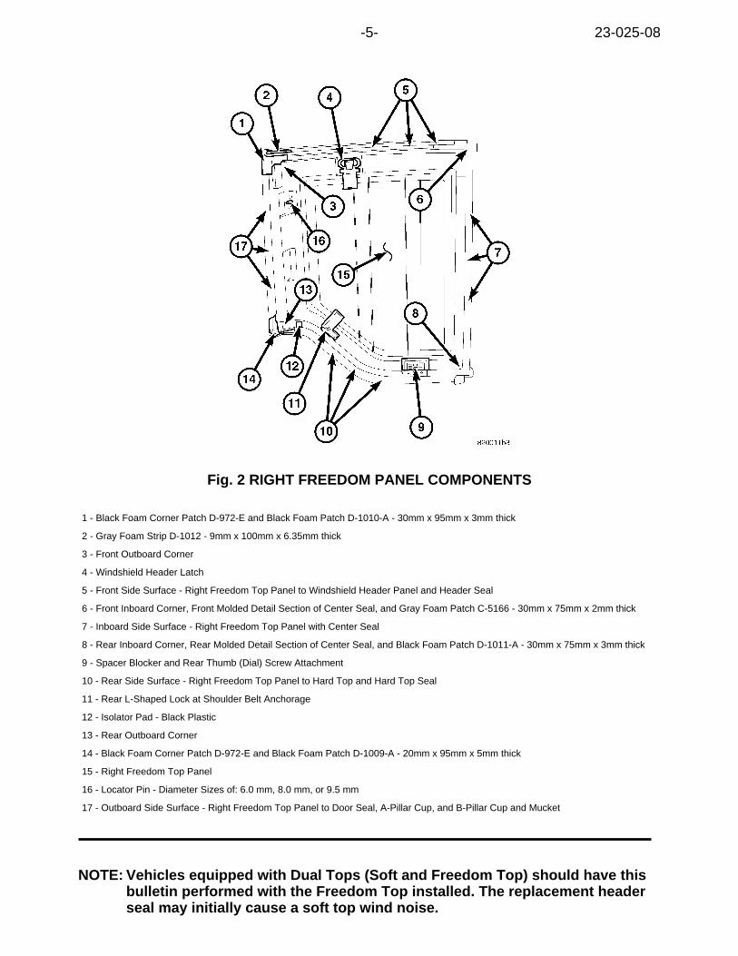
Fig. 2 RIGHT FREEDOM PANEL COMPONENTS
1 - Black Foam Corner Patch D-972-E and Black Foam Patch D-1010-A - 30mm x 95mm x 3mm thick
2 - Gray Foam Strip D-1012 - 9mm x 100mm x 6.35mm thick
3 - Front Outboard Corner
4 - Windshield Header Latch
5 - Front Side Surface - Right Freedom Top Panel to Windshield Header Panel and Header Seal
6 - Front Inboard Corner, Front Molded Detail Section of Center Seal, and Gray Foam Patch C-5166 - 30mm x 75mm x 2mm thick
7 - Inboard Side Surface - Right Freedom Top Panel with Center Seal
8 - Rear Inboard Corner, Rear Molded Detail Section of Center Seal, and Black Foam Patch D-1011-A - 30mm x 75mm x 3mm thick
9 - Spacer Blocker and Rear Thumb (Dial) Screw Attachment
10 - Rear Side Surface - Right Freedom Top Panel to Hard Top and Hard Top Seal
11 - Rear L-Shaped Lock at Shoulder Belt Anchorage
12 - Isolator Pad - Black Plastic
13 - Rear Outboard Corner
14 - Black Foam Corner Patch D-972-E and Black Foam Patch D-1009-A - 20mm x 95mm x 5mm thick
15 - Right Freedom Top Panel
16 - Locator Pin - Diameter Sizes of: 6.0 mm, 8.0 mm, or 9.5 mm
17 - Outboard Side Surface - Right Freedom Top Panel to Door Seal, A-Pillar Cup, and B-Pillar Cup and Mucket
NOTE: Vehicles equipped with Dual Tops (Soft and Freedom Top) should have thisbulletin performed with the Freedom Top installed. The replacement headerseal may initially cause a soft top wind noise.
-5- 23-025-08
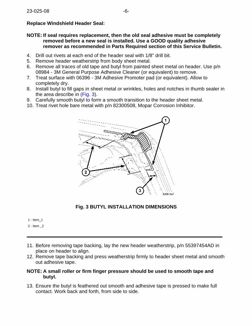
Replace Windshield Header Seal:
NOTE: If seal requires replacement, then the old seal adhesive must be completelyremoved before a new seal is installed. Use a GOOD quality adhesiveremover as recommended in Parts Required section of this Service Bulletin.
4. Drill out rivets at each end of the header seal with 1/8” drill bit.5. Remove header weatherstrip from body sheet metal.6. Remove all traces of old tape and butyl from painted sheet metal on header. Use p/n
08984 - 3M General Purpose Adhesive Cleaner (or equivalent) to remove.7. Treat surface with 06396 - 3M Adhesive Promoter pad (or equivalent). Allow to
completely dry.8. Install butyl to fill gaps in sheet metal or wrinkles, holes and notches in thumb sealer in
the area describe in (Fig. 3).9. Carefully smooth butyl to form a smooth transition to the header sheet metal.10. Treat rivet hole bare metal with p/n 82300508, Mopar Corrosion Inhibitor.
Fig. 3 BUTYL INSTALLATION DIMENSIONS
1 - Item_1
2 - Item _2
11. Before removing tape backing, lay the new header weatherstrip, p/n 55397454AD inplace on header to align.
12. Remove tape backing and press weatherstrip firmly to header sheet metal and smoothout adhesive tape.
NOTE: A small roller or firm finger pressure should be used to smooth tape andbutyl.
13. Ensure the butyl is feathered out smooth and adhesive tape is pressed to make fullcontact. Work back and forth, from side to side.
23-025-08 -6-
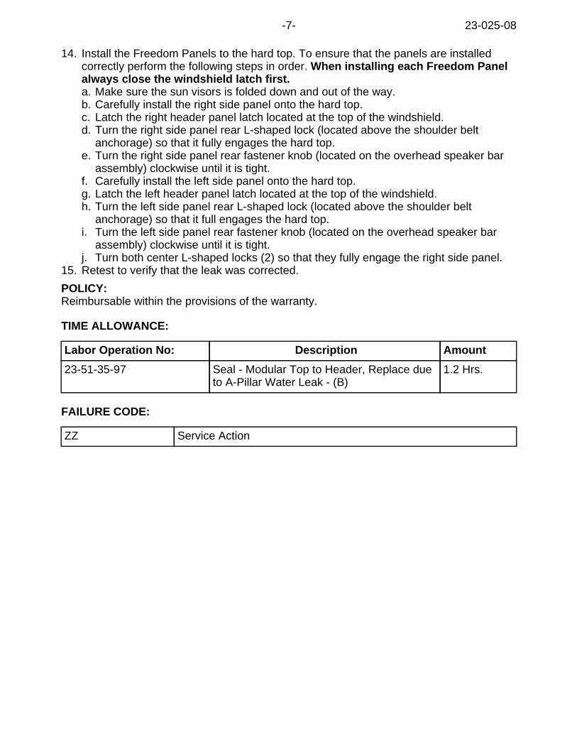
14. Install the Freedom Panels to the hard top. To ensure that the panels are installedcorrectly perform the following steps in order. When installing each Freedom Panelalways close the windshield latch first.a. Make sure the sun visors is folded down and out of the way.b. Carefully install the right side panel onto the hard top.c. Latch the right header panel latch located at the top of the windshield.d. Turn the right side panel rear L-shaped lock (located above the shoulder belt
anchorage) so that it fully engages the hard top.e. Turn the right side panel rear fastener knob (located on the overhead speaker bar
assembly) clockwise until it is tight.f. Carefully install the left side panel onto the hard top.g. Latch the left header panel latch located at the top of the windshield.h. Turn the left side panel rear L-shaped lock (located above the shoulder belt
anchorage) so that it full engages the hard top.i. Turn the left side panel rear fastener knob (located on the overhead speaker bar
assembly) clockwise until it is tight.j. Turn both center L-shaped locks (2) so that they fully engage the right side panel.
15. Retest to verify that the leak was corrected.
POLICY:Reimbursable within the provisions of the warranty.
TIME ALLOWANCE:
Labor Operation No: Description Amount
23-51-35-97 Seal - Modular Top to Header, Replace dueto A-Pillar Water Leak - (B)
1.2 Hrs.
FAILURE CODE:
ZZ Service Action
-7- 23-025-08
This bulletin is supplied as technical information only and is not an authorization for repair. No part of this publication may be reproduced, stored in a retrieval system,or transmitted, in any form or by any means, electronic, mechanical, photocopying, or otherwise, without written permission of Chrysler Group LLC.
THIS BULLETIN SUPERSEDES TECHNICAL SERVICE BULLETINS 23-002-08, DATEDJANUARY 15, 2008, 23-020-08, DATED JUNE 20, 2008, 23-025-08, DATED AUGUST26, 2008, AND 23-005-09, DATED MARCH 24, 2009 WHICH SHOULD BE REMOVEDFROM YOUR FILES. THIS IS A COMPLETE REVISION AND NO ASTERISKS HAVEBEEN USED TO HIGHLIGHT REVISIONS.
SUBJECT:Hard Top / Soft Top Water Leak Diagnosis
OVERVIEW:This bulletin introduces a New Water Leak Repair Manual that should be followedwhenever a vehicle is brought in with water leak concerns.
MODELS:
2007 - 2009 (JK) Wrangler
NOTE: This bulletin applies to vehicles equipped with a soft top, dual top and targatop (sales code GWK, VJ0, AEM and VJX).
SYMPTOM/CONDITION:Water leaks from hard or soft top and water on the carpet.
DIAGNOSIS:
A new approach to addressing water leak concerns on Wrangler models has beendeveloped and is announced with this Service Bulletin. The New Manual can be accessedthrough DealerCONNECT > Efiles. The file is found in the Service section > STAR Center> Misc Documents > JK Water Leak Repair Manual. The manual provides detailed colorgraphics and instructions to address many of the leak concerns associated with the Soft orHard top models. The manual is broken out by leak category (as listed below) andprovides all the necessary information and latest methods to make effective repairs. TheLabor Operations listed in the Service Bulletin can be used based on repair methods usedin the manual.
The JK Water Leak Repair Manual has a diagnosis road map that includes the followingcustomer concerns:
i. Water is on center of Instrument Panel / Shifterii. Water is on door trim panel or Instrument Panel at A-pillariii. Water at rear hard top panel / B-pillariv. Water is on the front carpet
NUMBER: 23-005-09 REV. A
GROUP: Body
DATE: August 12, 2009

POLICY:Reimbursable within the provisions of the warranty.
TIME ALLOWANCE:
Labor Operation No: Description Amount
23-51-35-95 Diagnosis Top System for WaterLeaks (B)
0.4Hrs.
23-51-35-97 Inspect and Replace WindshieldHeader Seal (B)
0.9Hrs.
23-51-10-90 Measure and Adjust Door Fitand Replace Primary Door Seal- One Door Only (B)
0.7Hrs.
23-51-41-91 Inspect A-Pillar Mucket Seal -One Side Only (B)
0.4Hrs.
23-51-41-92 Reseal Freedom Tops - BothFreedom Panels (B)
0.5Hrs.
23-42-63-90 Latch Freedom Panels - BothRight & Left Freedom Panels (B)
0.5Hrs.
23-51-35-98 Replace Hard Top Seal (B) 0.8Hrs.
23-51-41-93 Replace B-Pillar Mucket Seal -One Side Only (B)
0.4Hrs.
23-50-35-90 Repair Rear Wheel Flare Holes -Both Sides Right and Left Sides(B)
0.7Hrs.
23-50-40-90 Reseal Cowl Side Panel - OneSide Only (B)
0.5Hrs
FAILURE CODE:
ZZ Service Action
23-005-09 REV. A -2-