series mx4010 discharge air temperature control system
TRANSCRIPT
A40-SM2 Series Amplifier
Controlled Start-Up
• Fixes the modulation voltage and inducer state for a predetermined time after receiving EST input.
Inducer State
• Energizes/de-energizes on board SPDT relay setting inducer in low/high speed position.
Temperature Modulation
• Controls discharge air temperature by modulating Maxitrol E valve and setting relay states. Set point is selected with on board or remote temperature dial.
Minimum Input Limits
• Limits minimum VDC to E Valve when non-modulated section stages are operating.
Controlled Transition of Stage
• Adjustable timer used to delay transition of one relay stage to another. Eliminates or reduces unnecessary stage changes.
DESCRIPTION
1© 2019 Maxitrol Company, All Rights Reserved
The Series MX4010 discharge air temperature control system is for use with split manifold atmospheric indirect fired heaters. The split manifold operates as two independent manifold sections sharing a single inducer.
The controller senses and maintains a constant discharge air temperature by modulating one section of the manifold and staging the non-modulated section.
The Series MX4010 controller is used with the E42, E52, and E62 Series modulators. Typical applications achieve a turndown of approximately 10:1 during continuous operation.
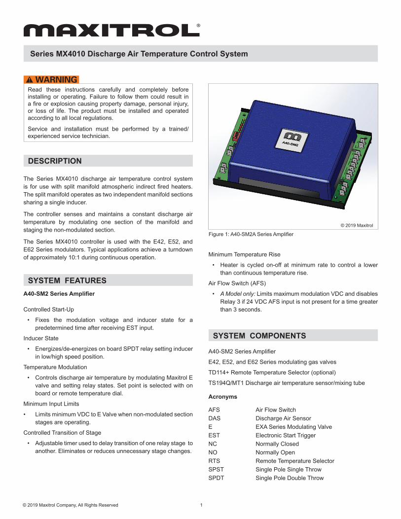
Figure 1: A40-SM2A Series Amplifier
Series MX4010 Discharge Air Temperature Control System
Read these instructions carefully and completely before installing or operating. Failure to follow them could result in a fire or explosion causing property damage, personal injury, or loss of life. The product must be installed and operated according to all local regulations.
Service and installation must be performed by a trained/experienced service technician.
SYSTEM FEATURES
© 2019 Maxitrol
Minimum Temperature Rise
• Heater is cycled on-off at minimum rate to control a lower than continuous temperature rise.
Air Flow Switch (AFS)
• A Model only: Limits maximum modulation VDC and disables Relay 3 if 24 VDC AFS input is not present for a time greater than 3 seconds.
A40-SM2 Series Amplifier
E42, E52, and E62 Series modulating gas valves
TD114+ Remote Temperature Selector (optional)
TS194Q/MT1 Discharge air temperature sensor/mixing tube
Acronyms
AFS Air Flow SwitchDAS Discharge Air SensorE EXA Series Modulating ValveEST Electronic Start TriggerNC Normally ClosedNO Normally OpenRTS Remote Temperature SelectorSPST Single Pole Single Throw SPDT Single Pole Double Throw
SYSTEM COMPONENTS

Dimensions: Amplifier: 8.5” L x 3.25” W x 2” HTemp Dial: 2.62” W x 3” H x 1.75” DMixing Tube Enclosure: 4.19” W x 4.19” H x 1.88” D[Tube Lengths: 9”, 12”, 23”]
NOTE: Dimensions are to be used only as an aid in designing clearance. Actual production dimensions may vary from those shown.
Ambient Temperature Limits Operating: -40° F to 150° F (-40° C to 66° C)RH: 95% non-condensing
Mounting Snap Track, multipoise
Power Supply24 VAC +10-15% (50/60 Hz), Class II Transformer20 VA - Rating for Maxitrol electronics and modulating gasvalve onlyHalf-Wave Rectified
NOTE: Polarity is specified - Transformer can be externally grounded
External WiringGauge: 18-22 AWG, copper only – meets application temperature rating
Connection: 1/4” male spade .032 thk
Relays: 1, 2, 3, 4A: When relay common voltage input is externally supplied (dry
contact), the voltage should not exceed 24 VAC, VDC nominalB: When relay common 24 VAC input is internally supplied, the
circuit load through shunt jumper J1, J2, or J3 should not exceed 1A
Rated load: 2A Max. @ 24 VAC (Resistive load)Max switching capacity: 50 VA (Resistive load)
Discharge Air Temperature Sensor (DAS)TS194Q1000Ω PRTD
DAS Mixing TubeMT1 or MT2 Series
Discharge Air Temperature SelectorTD114+ Remote Temperature Selector or on-board dial interface
Temperature Ranges:40° to 90° F (4° to 32° C)80° to 130° F (26° to 54° C)120° to 170° F (49° to 76° C)160° to 210° F (71° to 99° C)
EXA Modulating Gas ValvePower: 24 VAC, VDCRated load: 0.3 A maxControl Voltage: 0 - 10 VDC (Polarity Sensitive) 100kΩ Input Impedence
Performance
Relay 1 - Inducer
Trigger Voltage2 - 5 VDC nominal (modulation voltage) Span (Total)0.1 - 0.4 VDC
Relay 2 & 3 - Stage Transition
Delay Time60 - 360 seconds
Relay 4 - Thermostat Interrupt (Min. Temp Rise)
Trigger Voltage [Descending]0.05 - 0.10 VDC nominal output
Span (De-energize) [Ascending]0.05 - 0.10 VDC above trigger voltage
Timer5 - 55 seconds
Series MX4010 Discharge Air Temperature Control System
2© 2019 Maxitrol Company, All Rights Reserved
SPECIFICATIONS
IMPORTANT:
The MX40 Series is a discharge air temperature control, not a safety limit or safety control. A separate safety and/or limit control must be used when required by the application.

Series MX4010 Discharge Air Temperature Control System
SPECIFICATIONS
Reliability/Durability100% duty cycle
Sensitivity AdjustmentThe sensitivity control will allow the user to control the response of the system. Caution should be exercised in the use of this adjustment. Under normal usage the pointer should be located at approximately 2 o’clock.
If hunting is encountered (rapid oscillation), rotating the sensitivity adjustment counter-clockwise will dampen the oscillation – stabilizing the fl ame.
DO NOT adjust unless necessary, decreasing the sensitivity will increase the temperature “DROOP” of the system.
EST Input24 VAC continuous source (must share common with 24 VAC power)
NOTE: Commonly tied to gas valve 24 VAC input
Start-up Timer5 - 55 seconds
Start-up Modulator Voltage1 - 10 VDC
Minimum Voltage - Stage 3 & 40.5 - 5 VDC
AFS Fault Maximum Modulation Voltage (A suffi x only)2 - 10 VDC
NOTE: Shunt Jumper (J4) To Disable Feature
3
SWTemperature Range
40-90 °F 80-130 °F 120-170 °F 160-210 °F 1 OFF ON OFF OFF 2 OFF OFF ON OFF 3 OFF OFF OFF ON
On-Board Dial Remote Dial 4 ON OFF
Table 1: SW1 DIP Switch Settings
SHUNT JUMPER AND DIP SWITCH SETTINGS
J1 Connects T2 to T5
24 VAC - shunt jumper installed0 VAC - shunt jumper not installed
J2 Connects T2 to T8J3 Connects T9 to T10J4 Connects T2 to T18
Table 2: Shunt Jumper Settings
Figure 2: Shunt Jumper
Shunt Jumper(Shunt Installed)
Pin Header on PCB

Series MX4010 Discharge Air Temperature Control System
4© 2019 Maxitrol Company, All Rights Reserved
Figure 3: A40-SM2 Trimpot, LED, Dip Switch and Shunt Jumper Locations
© 2019 Maxitrol
1
5678910
2 3 4
Setting1 Start Time 6 Stage 3, 4 Time Delay2 Start Voltage 7 Relay 1 Trigger3 AFS Limit (“A” Suffix) 8 Relay 1 Deadband4 Stage 3, 4 Min VDC 9 Sensitivity5 Relay 4 Timer 10 Integral Temperature Dial
See Table 2, page 3
See Table 2, page 3
See Table 1, page 3
NOTE: Turn trimpot clockwise to increase, counter-clockwise to decrease

Series MX4010 Discharge Air Temperature Control System
WIRING DIAGRAM
Figu
re 3
: A40
-SM
2 W
iring
Dia
gram
5© 2019 Maxitrol Company, All Rights Reserved
© 2019 Maxitrol

Series MX4010 Discharge Air Temperature Control System
PCB CONNECTIONS
LED STATUS INDICATORS
No PCB Label Description NotesCOM
COMPower Common Internally connected to T1
T1 Power CommonPolarity Sensitive
T2 24 VAC + Power InputT3
EXA-
0-10 VDC Modulation Voltage - Polarity SensitiveT4 +
T5
R1
COM
Relay 1- SPDT
24 VAC - internal (J1)
T6 NCInducer Speed Stage
T7 NOT8
R2COM
Relay 2 - NO 24 VAC - internal (J2) T9 NOT10
R3COM
Relay 3 - NO 24 VAC - internal (J3)T11 NOT12
R4COM
Relay 4 - NC Thermostat Interrupt (Min temp rise mode)T13 NCT14
SENSOR Discharge Air Sensor TS194Q DAST15T16
DIAL Remote Temp Selector TD114+ Series RTST17
T18 AFS Air Flow Switch 24 VAC input (A model), shares COM groundT19 EST Start Trigger 24 VAC - Start trigger, shares COM ground
Status PCB Label ColorMain Power PWR BlueStart Up/Modulating MOD GreenRelay #1 Energized R1 RedRelay #2 Energized R2 RedRelay #3 Energized R3 RedRelay #4 Timer/Energized T/R4 RedAFS (“A” Suffix) AFS GreenStage Transition Timer STT Yellow
6© 2019 Maxitrol Company, All Rights Reserved

Series MX4010 Discharge Air Temperature Control System
OPERATIONCall For Heat (IDLE) Mode
• Thermostat relay is energized (completes W input)• A40-SM2 is powered with 24 VAC• E Valve is powered with 24 VAC• Inducer relay (R1) is de-energized, inducer operates in
high speed• Thermostat Interrupt relay (R2) is de-energized
LED: PWR, AFS (A Model)
Burner Start Up ModeEST receives 24 VAC input from the ignition control gas valve (MV) circuit
• Timer Starts and modulation voltage is fixed• Inducer Relay remains de-energized, inducer operates in
the high speed state NOTE: The system remains in this mode throughout Start up Timer durationLED: PWR, MOD (Flashes), AFS (A Model)
Operational Mode• Start up Timer expires• Set point temperature relative to sensed discharge air
temperature determines modulation VDC and mode• Relays are energized or de-energized based on modulation
voltage and stage timing in order to control set-point temperature
LED: PWR, MOD, R1, R2, R3 when energized AFS (A Model)
Minimum Temperature Rise Mode (Stage 0)
The heater can be cycled (on and off) to control a temperature rise lower than the minimum continuous temperature rise. Cycling is typically controlled by adding the NC Relay #4 into the burner control thermostat input circuit (W or TH).
Modulation voltage drops to ~0 VDC:• Result: Relay #4 timer starts, T/R4 LED flashes
Modulation voltage gradually increases before timer expires:• Result: Timer resets
Modulation voltage remains at 0 VDC long enough for timer to expire:
• Result: Relay #4 is energized
Energizing Relay #4 opens the thermostat circuit causing the heater to shutdown. Shutdown removes the 24 VAC EST input and the system defaults to the “Call for Heat” mode or remains off if thermostat input is not present.
7© 2019 Maxitrol Company, All Rights Reserved
Heater #1 - Modulated sectionHeater #2 - Non-modulated section
Stage EXA Modulation Voltage
R Mode % of total (Approx)**
0 0 VDC R4 energizedR1, R2, R3 de-energized
Heater #1 OFF <10%
I >0-4.5* VDC R1 energizedR2, R3, R4 de-energized
Heater #1 ONInducer-Low
Heater #2 OFF 10-30%
II 4.5*-10 VDC R1, R2, R3, R4 de-energized Heater #1 ONInducer-High
Heater #2 OFF 30-50%
III 2*-10 VDC R2 energizedR1, R3, R4 de-engerized
Heater #1 ONInducer-High
Heater #2 ONStage-Low
50-80%
IV 2*-10 VDC R2, R3 energizedR1, R4 de-energized
Heater #1 ONInducer-High
Heater #2 ONStage-High
80-100%
Table 3:
*Adjustable VDC setting
**Percentages are approximations

Series MX4010 Discharge Air Temperature Control System
OPERATION
8
Maxitrol Company 23555 Telegraph Rd., P.O. Box 2230 Southfield, MI 48037-2230 U.S.A.
www.maxitrol.com © 2019 Maxitrol Company,
All Rights Reserved. MX4010_MS_EN_04.2019
OPERATION: (see Table 3, page 7)
Stage I Minimum to 30% of total rating• Modulation Voltage: 0-4.5 VDC• Modulated section is operational• Inducer operates in low speed
LED: PWR, MOD, R1, AFS (Model A)
Stage II 30%-50% of total rating• Modulation Voltage: 4.5-10 VDC• Modulating section is operational• Inducer operates in high-speed
LED: PWR, MOD, AFS (Model A)
Stage II to Stage III Transition• Modulation voltage remains at 10 VDC for preset
time with no relays energizedLED: STT*
Stage III 50% to 80% of total rating• Modulation Voltage: 2** - 10 VDC• Modulating section is operational• Relay 2 is energized and 24 VAC output voltage is
supplied to non-modulated section start up relay• Non-modulated section is operational (low stage)
LED: PWR, MOD, R2, AFS (Model A)
Stage III to Stage II Transition• Modulation voltage remains at adjusted low VDC for
preset time with Relay 2 energizedLED: STT*
Stage III to Stage IV Transition• Modulation voltage remains at 10 VDC for a preset
time with Relay 2 energizedLED: STT*
Stage IV 80% to 100% of total rating• Modulation Voltage: 2** - 10 VDC.• Modulating section is operational• Relay 3 is energized and 24 VAC output is supplied
to the non-modulated 2 stage gas valve’s high input• Non-modulated section is operational (high stage)
LED: PWR, R2, R3, MOD, AFS (Model A)
Stage IV to Stage III Transition• Modulation voltage remains at adjusted low VDC for
preset time with Relay 3 energizedLED: STT*
AFS (A Suffix Only) Models
• Operating Condition #1 Relay 1 is energized and 24 VAC input is present or not present.Result: Normal operation of Stage I.
• Operating Condition #2Relay 1 is de-energized and 24 VAC input is present.Result: Normal operation of all stages.
• Operating Condition #3Relay 1 is de-energized and 24 VAC input is not present for duration greater than 3 seconds. Result:
- AFS Fault.- VDC output to valve is limited to user-selected voltage.- Relay 2 dependent on operating state when fault occurs.
Relay 3 is de-energized.- VDC output remains limited, even if the 24 VAC AFS
signal is re-established, until reset.
• Resetting AFS FaultPerform one of the following:
- Cycle main power - Cycle EST input- Energize Relay 1
AFS Fault Override: Shunt Jumper J4 AFS LED• Lit when 24 VAC input is present or Shunt Jumper J4 is
shunted.
* In addition to current stage LED’s
** Adjustable Min VDC