series emvii-6400ss specification sheet
TRANSCRIPT

8/8/2019 Series EMVII-6400SS Specification Sheet
http://slidepdf.com/reader/full/series-emvii-6400ss-specification-sheet 1/4
2-Piece, Standard Port, BronzeElectric Motor ValvesSizes: 1 ⁄ 4" – 3" (8 – 80mm)Series EMVII-6400SS 2-Piece, Standard Port, Bronze Motorized BallValves consist of an electrically actuated motor available in 115 or24 VAC models and features visual position indicator, manual over-ride, and can be mounted in any position. The EMVII-6400SS ballvalve features a 316 stainless steel ball and stem, Durafill® PTFEseats, stem packing, thrust washer and an adjustable packing nut.
Features• 316 stainless steel ball and stem
bottom loaded blowout proof stem
• Durafill® PTFE seats
• Adjustable PTFE packing
• Hole in stem slot of each ball valve to equalize pressurebetween the body cavity and the flow stream
• 115 VAC or 24 VAC motor
• 25% duty cycle (1 ⁄ 4" – 11 ⁄ 2") and 75% duty cycle (2" – 3")
• Standard auxiliary SPDT switch, 10 amps rating @ 115 VAC
• Adjustable cam provides the capability of properly aligningthe ball in both the open and closed position using a single,simple adjustment
• Accessible, clearly marked integral terminal strip assuresfast, easy wiring
• Standard position indicator
• Manual override standard
• Motor can be changed without draining system
• Mountable in any position
• Completely assembled
SpecificationsA 2-piece, standard port, bronze ball valve with electrically actuatedmotor to be installed as indicated on the plans. The electric motorshall have manual override, position indicator, be available in 115VAC or 24 VAC, and be mounted in any position with an adjustable
cam for easy alignment of the ball in open or close position, andclearly marked, easily accessible integral terminal strip for easeof wiring.
The ball valve shall have a 316 stainless steel ball and stem, PTFEseats, and adjustable packing. Top loaded stems or valves withoutadjustable packing are not acceptable. Valves rated no less that600psi (41 bars) WOG/100psi (7 bars) WSP 1 ⁄ 4" – 2", 400psi(27.6 bars) WOG/100psi (7 bars) WSP 21 ⁄ 2" and 3". Supply valvestested, mounted, and fully assembled for installation. Valve shallbe a Watts Regulator Company Series EMVII-6400SS.
For Commercial and Industrial Applications
ES-EMVII-6400SS
Job Name ––––––––––––––––––––––––––––––––––––––––––– Contractor ––––––––––––––––––––––––––––––––––––––––––––
Job Location ––––––––––––––––––––––––––––––––––––––––– Approval –––––––––––––––––––––––––––––––––––––––––––––
Engineer –––––––––––––––––––––––––––––––––––––––––––– Contractor’s P.O. No. ––––––––––––––––––––––––––––––––––
Approval –––––––––––––––––––––––––––––––––––––––––––– Representative ––––––––––––––––––––––––––––––––––––––––
Pressure – TemperatureMaximum Temperature: 150° F (66° C)1 ⁄ 4" – 2" (8 – 50mm)
600psi (41 bars) WOG
100psi (7 bars) WSP
21 ⁄ 2" and 3" (65 and 80mm)
400psi (27.6 bars) WOG
100psi (7 bars) WSP
Operating Data115 VAC
5 amps max @ 40 sec. cycle time 1 ⁄ 4" – 11 ⁄ 2"
.75 amp max @ 5 sec. cycle time 2"
.50 amp max @ 25 sec. cycle time 21 ⁄ 2" and 3"
24 VAC
2.2 amps max @ 40 sec. cycle time 1 ⁄ 4" – 11 ⁄ 2"
4.0 amps max @ 5 sec. cycle time 2"
3.0 amp max @ 25 sec. cycle time 21 ⁄ 2" and 3"
Applications
• Zone control valve for space heating with hot water or steam• Zone control valve for air conditioning with chilled water
• Remotely operated valve for control of process liquidsor gases (ie: steam, water or air)
• Drain or blow-down valve to eliminate water from compressedair lines and systems
EMVII-6400SS
Series EMVII-6400SS
Watts product specifications in U.S. customary units and metric are approximate and are provided for reference only. For precise measurements,
please contact Watts Technical Service. Watts reserves the right to change or modify product design, construction, specifications, or materials with-
out prior notice and without incurring any obligation to make such changes and modifications on Watts products previously or subsequently sold.
Durafill® is a registered trademark of Cargill, Limited.

8/8/2019 Series EMVII-6400SS Specification Sheet
http://slidepdf.com/reader/full/series-emvii-6400ss-specification-sheet 2/4
Wiring Diagram #1 ( 1 ⁄ 4" – 11 ⁄ 2")Electrical diagram with 24V control circuit, 24V Motorvalve,SPDT thermostat.
Sample Installation #1Use of Watts Electric Motorvalve as a zone control for hot wateror steam space heating. Valve opens upon temperature drop.Closes when demand for heat is satisfied.
Sample Installation #2Cooling with refrigerated water and operating forced air fanwith auxiliary switch. Motorvalve opens and starts blower upontemperature rise. Shuts off blower and closes when temperaturedrops to thermostat setting.
Wiring Diagram #2 ( 1 ⁄ 4" – 11 ⁄ 2")Electrical diagram with 115V control circuit, 115V Motorvalve,line voltage SPDT cooling thermostat, 115V blower.
Wiring Diagram #3 (2" – 3")
Actuator shown in counter-clockwise extreme of travel, or ‘Open’ position.NOTES:
1. 2", 21 ⁄ 2" and 3" motorvalves are supplied with wiring terminal stripshaving 16 terminals.
2. Each actuator must be powered through its own individual switchcontacts to avoid cross feed.
3. Motor has a thermal protector as shown in diagram.
Terminal Function ( 1 ⁄ 4" – 11 ⁄ 2")1 ⁄ 4" – 11 ⁄ 2" motorvalves are supplied with wiring terminal strips havingsix terminals. Terminals 4, 5 and 6 operate the motorvalve, whileterminals 1, 2 and 3 are connected to an internal SPDT auxiliary switch.
NOTE: 24 VAC or 115 VAC models, the following terminal explanationwill always apply.
NOTE: 1 ⁄ 4" - 11 ⁄ 2" EMVII-6400SS-24-40 will operate with a 40 VA transformer.Thermostat must be capable of handling amp rating at stall.
WATTS MOTORVALVE
A = CommonB = Normally open
C = Normally closed
A = CommonB = Normally OpenC = Normally Closed
WATTS MOTORVALVE
CUSTOMERPROVIDEDLIGHTS ANDSWITCHING
SEE NOTE 1
AC VOLTS
C u s t o m e r s u p p l i e d
e x t e r n a l c o m p o n e n t s
MOTORVALVETERMINALS
115V
115V FANMOTOR
115V SPDTCOOLING
THERMOSTAT
115V Line
115V Line
AUXILIARYSWITCH
TERMINALS
MOTORVALVETERMINALS
(24V)
24V TRANSFORMERSEE NOTE
Customer suppliedexternal components
24V SPDTTHERMOSTAT
COLD WATER IN
THERMOSTAT
COOLING COIL
FORCEDAIRFAN
COLD WATER RETURN
HEAT TRANSFER MEANSHOT WATEROR STEAM-IN
HOT WATER RETURN ORSTEAM CONDENSATE RETURN
STEAM TRAP(Steam System)
THERMOSTAT(SPDT)
B L A C K
W H I T E
B L U E
Y E L L O W
B R O W N
1 2 3 4 5 6 7 8 9 10 11 12 13 14 15 16
12
3
4
56
B
C
A
BA
TERMINAL NO. FUNCTION
Operating terminal #4 When power is applied,valve will open.
Operating Terminal #5 CommonOperating Terminal #6 When power is applied,
valve will close.Auxiliary Switch Terminal #1 Makes when valve is fully open.Auxiliary Switch Terminal #2 CommonAuxiliary Switch Terminal #3 Makes when valve is not fully open.
8/8/2019 Series EMVII-6400SS Specification Sheet
http://slidepdf.com/reader/full/series-emvii-6400ss-specification-sheet 3/4
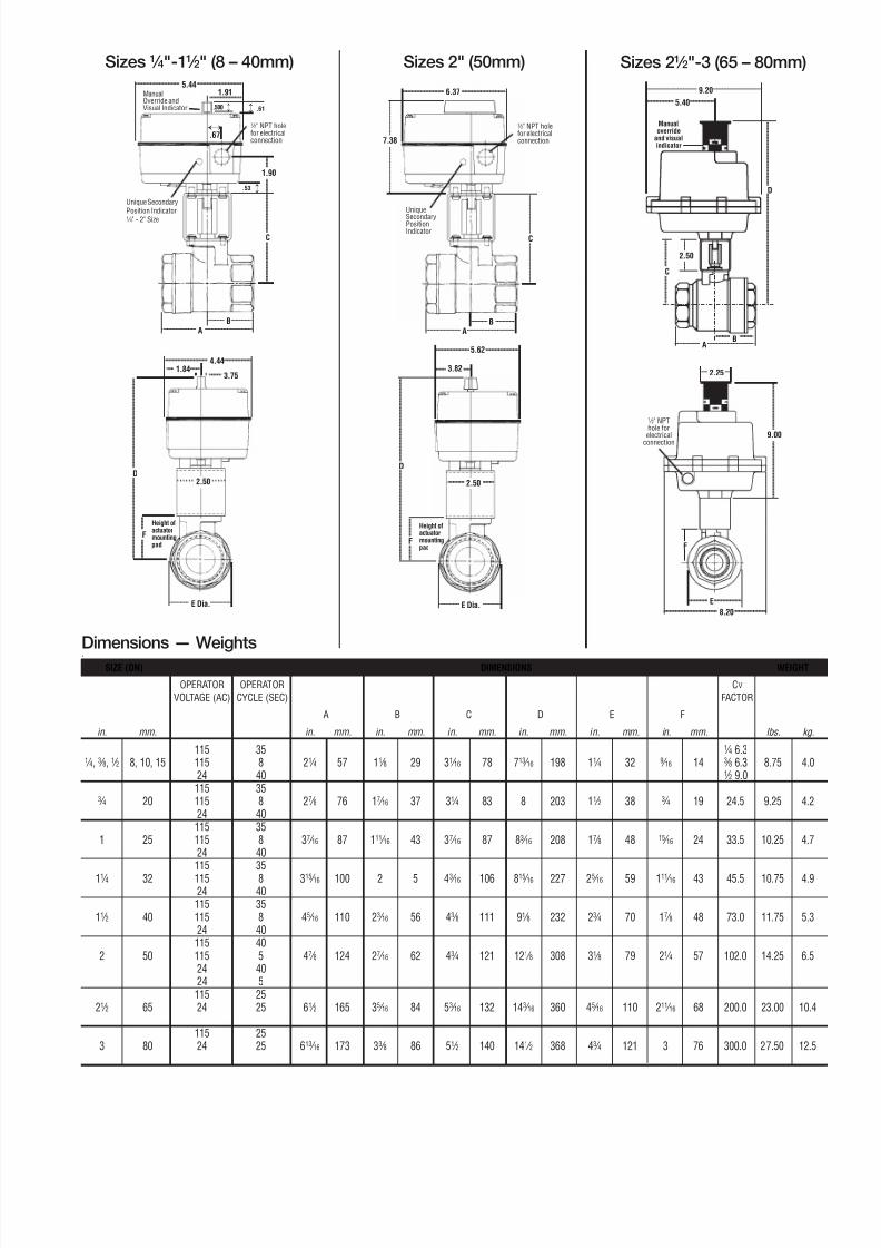
Manualoverride
and visualindicator
ManualOverride andVisual Indicator
Unique SecondaryPosition Indicator1 ⁄ 4" - 2" Size
1 ⁄ 2" NPT holefor electricalconnection
1 ⁄ 2" NPThole for
electricalconnection
1.91
1.90
.53
C
BA
.500
4.441.84
3.75
2.50D
E Dia.
F
Height ofactuatormountingpad
D
B
C
A
2.50
8.20
E
F
Sizes 2" (50mm) Sizes 21 ⁄ 2"-3 (65 – 80mm)Sizes 1 ⁄ 4"-11 ⁄ 2" (8 – 40mm)
↕
↕
↕ .61
↕
Unique
SecondaryPositionIndicator
1 ⁄ 2" NPT holefor electricalconnection
C
BA
5.62
3.82
2.50
D
E Dia.
F
Height ofactuatormountingpad
6.37
Dimensions — Weights.
SIZE (DN) DIMENSIONS WEIGHT
OPERATOR OPERATOR CV
VOLTAGE (AC) CYCLE (SEC) FACTOR
A B C D E F
in. mm. in. mm. in. mm. in. mm. in. mm. in. mm. in. mm. lbs. kg.
115 35 1 ⁄ 4 6.31 ⁄ 4, 3 ⁄ 8, 1 ⁄ 2 8, 10, 15 115 8 21 ⁄ 4 57 11 ⁄ 8 29 31 ⁄ 16 78 713 ⁄ 16 198 11 ⁄ 4 32 9 ⁄ 16 14 3 ⁄ 8 6.3 8.75 4.0
24 40 1 ⁄ 2 9.0115 35
3 ⁄ 4 20 115 8 27 ⁄ 8 76 17 ⁄ 16 37 31 ⁄ 4 83 8 203 11 ⁄ 2 38 3 ⁄ 4 19 24.5 9.25 4.224 40115 35
1 25 115 8 37 ⁄ 16 87 111 ⁄ 16 43 37 ⁄ 16 87 83 ⁄ 16 208 17 ⁄ 8 48 15 ⁄ 16 24 33.5 10.25 4.724 40115 35
11 ⁄ 4 32 115 8 315 ⁄ 16 100 2 5 43 ⁄ 16 106 815 ⁄ 16 227 25 ⁄ 16 59 111 ⁄ 16 43 45.5 10.75 4.924 40115 35
11 ⁄ 2 40 115 8 45 ⁄ 16 110 23 ⁄ 16 56 43 ⁄ 8 111 91 ⁄ 8 232 23 ⁄ 4 70 17 ⁄ 8 48 73.0 11.75 5.324 40115 40
2 50 115 5 47 ⁄ 8 124 27 ⁄ 16 62 43 ⁄ 4 121 121 ⁄ 8 308 31 ⁄ 8 79 21 ⁄ 4 57 102.0 14.25 6.524 4024 5115 25
21 ⁄ 2 65 24 25 61 ⁄ 2 165 35 ⁄ 16 84 53 ⁄ 16 132 143 ⁄ 16 360 45 ⁄ 16 110 211 ⁄ 16 68 200.0 23.00 10.4
115 253 80 24 25 613 ⁄ 16 173 33 ⁄ 8 86 51 ⁄ 2 140 141 ⁄ 2 368 43 ⁄ 4 121 3 76 300.0 27.50 12.5
7.38
9.20
5.40
9.00
.67
5.44
2.25

8/8/2019 Series EMVII-6400SS Specification Sheet
http://slidepdf.com/reader/full/series-emvii-6400ss-specification-sheet 4/4
For additional information, visit our web site at: www.watts.com
ES-EMVII-6400SS 1117 © 2011 Watts
USA: No. Andover, MA • Tel. (978) 688-1811 • Fax: (978) 794-1848 • www.watts.com
Canada: Burlington, ON • Tel. (905) 332-4090 • Fax: (905) 332-7068 • www.wattscanada.ca
A Watts Water Technologies Company