series advanced recloser protection & control rer620 ... · relion 620® series advanced...
TRANSCRIPT

Relion 620® series
Advanced Recloser Protection & Control RER620Product guide

ABB 2
1MAC301920-PG Rev. A
Issued: 12.29.2010
Advanced Recloser Protection and Control
RER620
Product Version 1.0
Contents
Disclaimer
The information in this document is subject to change without notice and should not be construed as a commitment by ABB Inc. ABB Inc. assumes no responsibility for any errors that may appear in this document.
Copyright © 2010 ABB
All rights reserved.
Trademarks
ABB is a registered trademark of ABB Group. All other brand or product names mentioned in this document may be trademarks or registered trademarks of their respective holders.
1 Description . . . . . . . . . . . . . . . . . . . . . . . . . . . . . 3
2 Standard configurations . . . . . . . . . . . . . . . . 4 - 6
3 Protection functions . . . . . . . . . . . . . . . . . . . 7 - 8
4 Application . . . . . . . . . . . . . . . . . . . . . . . . . 9 - 12
5 Supported ABB solutions . . . . . . . . . . . . . 13 - 14
6 Control . . . . . . . . . . . . . . . . . . . . . . . . . . . . . . . 15
7 Measurements . . . . . . . . . . . . . . . . . . . . . . . . . 15
8 Digital fault recorder . . . . . . . . . . . . . . . . . . . . . 15
9 Event recorder . . . . . . . . . . . . . . . . . . . . . . . . . 15
10 Fault recorder . . . . . . . . . . . . . . . . . . . . . . . . . 16
11 Recloser/circuit-breaker condition monitoring 16
12 Trip-circuit monitoring . . . . . . . . . . . . . . . . . . 16
13 Self-diagnostics . . . . . . . . . . . . . . . . . . . . . . . 16
14 Fuse failure protection . . . . . . . . . . . . . . . . . . 16
15 Uninterruptable Power Supply (UPS) . . . . . . . 17
16 Universal Power Driver (UPD) . . . . . . . . . . . . . 17
17 Access control . . . . . . . . . . . . . . . . . . . . . . . . 18
18 Inputs and outputs . . . . . . . . . . . . . . . . . . . . . 18
19 Communications . . . . . . . . . . . . . . . . . . 19 - 20
20 Technical data . . . . . . . . . . . . . . . . . . . . 21 - 39
21 Display . . . . . . . . . . . . . . . . . . . . . . . . . . . . . . 40
22 Local HMI . . . . . . . . . . . . . . . . . . . . . . . . . 41-42
23 Mounting methods . . . . . . . . . . . . . . . . . . . . . 43
24 IED case and drawout unit . . . . . . . . . . . . . . . 43
25 Selection and ordering data . . . . . . . . . . . . . . 44
26 Accessories and ordering data. . . . . . . . . . . . 45
27 Tools . . . . . . . . . . . . . . . . . . . . . . . . . . . . . 45-46
28 Terminal diagrams . . . . . . . . . . . . . . . . . . . . . 47
29 Certificates . . . . . . . . . . . . . . . . . . . . . . . . . . . 48
30 References . . . . . . . . . . . . . . . . . . . . . . . . . . . 49
31 Functions, codes and symbols . . . . . . . 50 - 52
32 Document revision history . . . . . . . . . . . . . . . 53
33 Notes . . . . . . . . . . . . . . . . . . . . . . . . . . . . 54-55

ABB 3
Advanced Recloser Protection and Control
RER620
Product Version 1.0
1MAC301920-PG Rev. A
Issued: 12.29.2010
1. Description
The RER620 is a dedicated recloser IED (intelligent electronic device) perfectly aligned for the protection, control, measurement and supervision of utility substations and industrial power systems including radial, looped and meshed distribution networks with or without distributed power generation. RER620 is a member of ABB’s Relion® family and a part of its 620 protection and control product series. The 620 series IEDs are characterized by their compactness and withdraw-able unit design.
Re-engineered from the ground up, the 620 series has been designed to unleash the full potential of the IEC 61850 standard for communication and interoperability between substation automation devices. The IED provides main protection for overhead lines and cable feeders in distribution networks. The IED is also used as back-up protection in applications, where an independent and redundant protection system is required.
Unique RER620 features• Six setting groups• Drawout design• High impedance (HIZ) fault detection• Integrated Loop Control• Support both single and three phase tripping for
improved feeder performance• Easy integration of Distributed generation on al-
ready installed recloser• Large, easy to read LCD screen “Quick” pushbut-
tons for easy operation Scalable hardware includ-ing binary inputs/outputs, different communica-tion interfaces
• Integrated Web browser for easy setting and op-eration
• Use of IEC61850 and GOOSE messaging com-munications for high-speed protection, fault iso-lation and service restoration
• Easy integration into Ethernet or serial-based communication networks with standard DNP3, IEC 60870-5-101, IEC 60870-5-104, Modbus and IEC 61850
• By using Application Configuration Tool – ACT of PCM600 tool, different applications such as recloser, switch, sectionalizer can be made easily
• Field data from recloser control, Sequence of Events, digital waveform recording, advanced metering, setting etc. can be achieved by using
just simple Internet Explorer. No tools need to be installed on Filed personnel computer
• Environmentally friendly design with RoHS com-pliance
The RER620 provides main protection for overhead lines of distribution substations. It can be applied for protection and control of grounded and ungrounded distribution systems.
The RER620 is the most powerful, advanced re-closer protection relay in its class, perfectly offer-ing time and instantaneous overcurrent, negative sequence overcurrent, phase discontinuity, breaker failure imbedded loop control performing automatic loop restoration functions, commonly accepted as a means to significantly improve circuit reliability and to provide more effective system operation, and volt-age metering and protection. The relay also features optional high impedance fault (HIZ) and sensitive earth fault (SEF) protection for grounded and un-grounded distribution systems. Also, the relay incor-porates a flexible three and single-phase multi-shot auto-reclose function for automatic feeder restora-tion in temporary faults on overhead lines.
The RER620 also integrates basic control func-tionality, which facilitates the control of one circuit breaker or recloser via the relay’s front panel human machine interface (HMI) or remote control system. To protect the relay from unauthorized access and to maintain the integrity of information, the relay has been provided with a four-level, role-based user au-thentication system, with individual passwords for the viewer, operator, engineer, and administrator levels. The access control system applies to the front panel HMI, embedded web browser based HMI, and the PCM600 relay setting and configuration tool. RER620 supports the new IEC 61850 standard for inter-device communication in substations or along the feeder. The relay also supports the industry stan-dard DNP3.0 , IEC 60870-5-101, IEC 60870-5-104 and Modbus® protocols.

ABB 4
1MAC301920-PG Rev. A
Issued: 12.29.2010
Advanced Recloser Protection and Control
RER620
Product Version 1.0
2. Standard configurations
The RER620 relay’s main application is feeder protection and control and offers one standard configuration whose relay functions and features are based on the ordering code. See Tables 1 for details. The standard signal configuration can be altered by means of the graphical signal matrix or the optional graphical application functionality of the Protection and Control IED Manager PCM600. Further, the application configuration functionality of PCM600 supports the creation of multi-layer logic functions utilizing various
logical elements including timers and flip-flops. By combining protection functions with logic function blocks, the IED configuration can be adapted to user specific application requirements.
Configuration includes standard metering, monitoring and control features and sequence of event, fault and digital waveform recording. Advanced Ethernet communications included standard with parallel support of DNP3.0 Level 2+*, IEC 60870-5-104, Modbus and IEC61850 and SNTP over TCP/IP. Additional RS-232 and RS-485 serial communication ports are available as options that support user programmable DNP3.0 Level 2+*, IEC 60870-5-101, or Modbus protocols. Included with the optional serial communication ports is IRIG-B time synchronization.
*The DNP3.0 Level 2+ implementation includes some Level 3 functionality.
Table 1. Supported functions RER620FunctionalityProtectionThree-phase non-directional overcurrent protection with single phase trip option, low stage ● 1)
Three-phase non-directional time overcurrent protection with single phase trip option, high stage 1 ● 1)
Three-phase non-directional time overcurrent protection with single phase trip option, high stage 2 ● 1)
Three-phase non-directional instantaneous overcurrent protection with single phase trip option ● 1)
Non-directional time overcurrent ground-fault protection, low stage ● 6)
Non-directional time overcurrent ground-fault protection, high stage 1 ● 6)
Non-directional time overcurrent ground-fault protection, high stage 2 ● 6)
Non-directional instantaneous time overcurrent ground-fault protection ● 6)
Non-directional sensitive earth-fault ● 7)
Negative sequence non-directional time overcurrent protection 1 ●Negative sequence non-directional time overcurrent protection 2 ●Phase discontinuity protection ●Three-phase inrush detector ●Three-phase directional overcurrent protection, low stage 1 ● 4)
Three-phase directional overcurrent protection, low stage 2 ● 4)
Directional ground-fault protection, low stage 1 ●Directional ground-fault protection, low stage 2 ●Three-phase overvoltage 1, source 1 low stage ● 2)
Three-phase overvoltage 2, source 1 high stage ●Three-phase overvoltage 3, source 2 low stage ● 3)
Three-phase undervoltage 1, source 1 low stage ● 2)
Three-phase undervoltage 2, source 1 high stage ●Three-phase undervoltage 3, source 2 low stage ● 3)
Positive sequence overvoltage protection, source 1 ● 2)
Positive sequence overvoltage protection, source 2 ● 3)
Negative sequence overvoltage protection, source 1 ● 2)
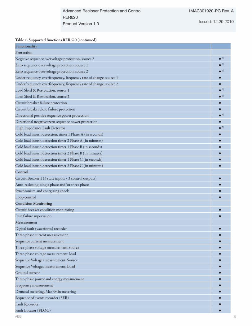
ABB 5
Advanced Recloser Protection and Control
RER620
Product Version 1.0
1MAC301920-PG Rev. A
Issued: 12.29.2010
Table 1. Supported functions RER620 (continued)FunctionalityProtectionNegative sequence overvoltage protection, source 2 ● 3)
Zero sequence overvoltage protection, source 1 ● 2)
Zero sequence overvoltage protection, source 2 ● 3)
Underfrequency, overfrequency, frequency rate of change, source 1 ●Underfrequency, overfrequency, frequency rate of change, source 2 ●Load Shed & Restoration, source 1 ● 2)
Load Shed & Restoration, source 2 ● 3)
Circuit breaker failure protection ●Circuit breaker close failure protection ●Directional positive sequence power protection ● 4)
Directional negative/zero sequence power protection ●High Impedance Fault Detector ● 7)
Cold load inrush detection, timer 1 Phase A (in seconds) ●Cold load inrush detection timer 2 Phase A (in minutes) ●Cold load inrush detection timer 1 Phase B (in seconds) ●Cold load inrush detection timer 2 Phase B (in minutes) ●Cold load inrush detection timer 1 Phase C (in seconds) ●Cold load inrush detection timer 2 Phase C (in minutes) ●ControlCircuit Breaker 1 (3 state inputs / 3 control outputs) ●Auto-reclosing, single phase and/or three phase ●Synchronism and energizing check ●Loop control ●Condition MonitoringCircuit-breaker condition monitoring ●Fuse failure supervision ●MeasurementDigital fault (waveform) recorder ●Three-phase current measurement ●Sequence current measurement ●Three-phase voltage measurement, source ●Three-phase voltage measurement, load ●Sequence Voltages measurement, Source ●Sequence Voltages measurement, Load ●Ground current ●Three-phase power and energy measurement ●Frequency measurement ●Demand metering, Max/Min metering ●Sequence of events recorder (SER) ●Fault Recorder ●Fault Locator (FLOC) ●

ABB 6
1MAC301920-PG Rev. A
Issued: 12.29.2010
Advanced Recloser Protection and Control
RER620
Product Version 1.0
Table 1. Supported functions RER620 (continued)Other functionsUninterruptable Power Supply (UPS) including: battery charger, heater control, auxiliary power for external modems, voltage boost ● 5)
Universal Power Driver (UPD) for ABB GridShield series of reclosers and others ●Programmable buttons (16 buttons) ●Move function block (8 outputs) ●Pulse timer (8 timers) ●Generic control points (16 outputs) ●Set reset flip flops (8 outputs) ●Time delay off timers (8 timers) ●Time delay on timers (8 timers) ●Move function block (8 outputs) ●Pulse timer (8 timers) ●Generic control points (16 outputs) ●Set reset flip flops (8 outputs) ●Time delay off timers (8 timers) ●Time delay on timers (8 timers) ●1) Three phase tripping is always enabled when ordering RER620. Single phase tripping is optional
2) Voltages connected to X[130] terminals 1 - 9 are considered as Source 1
3) Voltages connected to X[130] terminals 11 - 18 are considered as Source 2
4) Polarizing voltage is taken from X[130] terminals 1 - 9
5) UPS is mandatory when using RER620 with ABB GridShield reclosers
6) I0 is calculated
7) IG is measured from the fourth CT (X[120], terminal 13-14) input of RER620
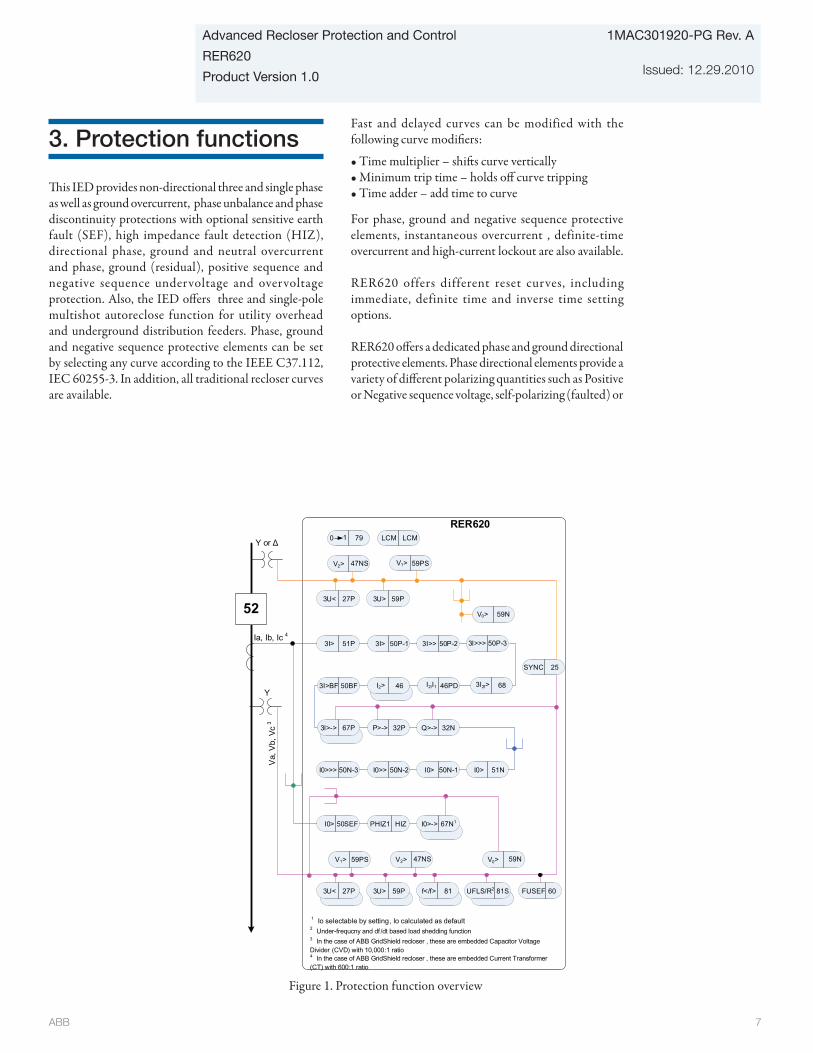
ABB 7
Advanced Recloser Protection and Control
RER620
Product Version 1.0
1MAC301920-PG Rev. A
Issued: 12.29.2010
Figure 1. Protection function overview
RER620
1 Io selectable by setting, Io calculated as default
52
Υ or Δ
Va,
Vb,
Vc
3
51P3I> 50P-13I> 50P-23I>> 50P-33I>>>
6846PD 3I2f>I2/I1I2>50BF3I>BF 46I2>
67P3I>->
51NI0>50N-1I0>50N-2I0>>50N-3I0>>>
32PP>-> 32NQ>->
50SEFI0> HIZPHIZ1 67N1I0>->
Ia, Ib, Ic 4
27P3U< 59P3U> 81f</f> 81SUFLS/R2
2 Under-frequcny and df /dt based load shedding function
59PSV1> 59NV0>
60FUSEF
Υ
27P3U< 59P3U>
47NSV2>
47NSV2> V1> 59PS
59NV0>
25SYNC
0 791 LCMLCM
3 In the case of ABB GridShield recloser , these are embedded Capacitor Voltage Divider (CVD) with 10,000:1 ratio4 In the case of ABB GridShield recloser , these are embedded Current Transformer (CT) with 600:1 ratio
3. Protection functions
This IED provides non-directional three and single phase as well as ground overcurrent, phase unbalance and phase discontinuity protections with optional sensitive earth fault (SEF), high impedance fault detection (HIZ), directional phase, ground and neutral overcurrent and phase, ground (residual), positive sequence and negative sequence undervoltage and overvoltage protection. Also, the IED offers three and single-pole multishot autoreclose function for utility overhead and underground distribution feeders. Phase, ground and negative sequence protective elements can be set by selecting any curve according to the IEEE C37.112, IEC 60255-3. In addition, all traditional recloser curves are available.
Fast and delayed curves can be modified with the following curve modifiers:
• Time multiplier – shifts curve vertically • Minimum trip time – holds off curve tripping• Time adder – add time to curve
For phase, ground and negative sequence protective elements, instantaneous overcurrent , definite-time overcurrent and high-current lockout are also available.
RER620 offers different reset curves, including immediate, definite time and inverse time setting options.
RER620 offers a dedicated phase and ground directional protective elements. Phase directional elements provide a variety of different polarizing quantities such as Positive or Negative sequence voltage, self-polarizing (faulted) or

ABB 8
1MAC301920-PG Rev. A
Issued: 12.29.2010
Advanced Recloser Protection and Control
RER620
Product Version 1.0
cross-polarizing (healthy voltages). To secure a reliable and correct directional operation in case of close short circuits when polarizing quantity might be low, RER620 implements a memory function.
In the case of failure in the secondary circuits between the voltage transformers and RER620 to avoid misoperation of the voltage based functions, RER620 includes a Fuse failure/Loss-of potential functionality. Fuse failure/Loss-of potential functionality can detect failure in one, two or three phase failures in the secondary VT circuit.
Frequency protection including overfrequency, underfrequency and frequency rate-of-change protection is offered in RER620 with standard configuration. In addition, integrated load shedding and restoration function based on frequency and rate-of change is included. In the applications when closing of breakers between asynchronous networks is needed, energizing and synchronizing function is provided in the standard configuration. In the application when high sensitivity is required, positive and negative sequence directional power elements are included in the standard configuration.
Recloser function in RER620 provides up to five programmable auto-reclose shots which can perform one to five successive auto-reclosings of desired type and duration, for instance one high-speed and one delayed auto-reclosing. Recloser function has the ability to operate on three poles independently. This feature allows it to be used in distribution networks, where the bulks of loads are single phase and it is not always necessary to operate all three poles in case of fault on one phase. Visual indication on programmable LED is provided when recloser is in the lockout. By using programmable push button, reclosing functionality can be disabled or enabled.
In several applications, such as fuse-saving applications involving down-stream fuses, tripping and initiation of shot 1 should be fast (instantaneous or short-time delayed). The tripping and initiation of shots 2, 3 and definite tripping time should be delayed. In such applications, RER620 includes a sequence coordination feature. Recloser feature in RER620 includes Switch Onto the Fault (SOTF) which prevents reclosing sequence when recloser/breaker is manually closed on forgotten grounding after a maintenance work along
the power line. During the stormy weather, there might be many autoreclose shots within a few minutes. These types of faults can easily damage recloser/breaker if the reclose function is not blocked based on frequent operation counters.
Figure 1 shows the protection functions available for the standard configuration.

ABB 9
Advanced Recloser Protection and Control
RER620
Product Version 1.0
1MAC301920-PG Rev. A
Issued: 12.29.2010
4. Application
To make ordering simple, the RER620 always includes three phase CTs, sensitive earth fault (SEF)/ high impedance (HIZ) CT input and six VT inputs to perfectly match required distribution feeder protection, control and metering functionality. Customer programmable phase and ground CT and VT secondary nominal settings and wide protection setting ranges increase the RER620 flexibility of application. Directional ground-fault protection is mainly used in isolated neutral or compensated networks, whereas non-directional ground-fault protection is intended for directly or low impedance grounded networks. The IED can also be used for protection of ring-type and meshed distribution networks as well of radial networks containing distributed power generation.
Measured residual current from the fourth CT input (0.2/1A) is used by the Sensitive Earth Fault and High Impedance Detection. The residual current for the ground-fault protection derived from the phase currents is used by other time overcurrent and instantaneous ground protective elements. When applicable, the core-balance current transformers can be used for measuring the residual current, especially when sensitive ground-fault protection is required. In the case when high sensitivity is required to detect the fault in the range of 1A primary current, protection functions can be set to the fourth CT input with 0.2A nominal tap setting.
The standard configuration offers directional earth-fault protection with residual voltage calculated from the phase voltages. Furthermore, the standard configuration include fuse failure supervision. In addition standard configuration offers directional overcurrent protection, overvoltage and undervoltage protection, positive-sequence and negative-sequence overvoltage protection and residual voltage protection.
To perform automatic loop restoration functions, commonly accepted as a means to significantly improve circuit reliability and to provide more effective system operation, embedded Loop Control functionality is provided as a standard feature. In such applications there is no communication between the recloser control IEDs and automatic fault isolation and restoration is accomplished with Loop control functionality.
The loop control feature in RER620 supports (please refer to Figure 4):
Sectionalizing recloser:Opens in response to a downstream fault or to a loss of phase voltage from an upstream circuit.
Midpoint recloser:It supports loop control by automatically altering the RER620 settings in accordance with changing voltage conditions.
Tiepoint recloser:It closes in response to a loss of all phase voltages from one source if the other source phase voltages are live.
In the case there is a communication (via fiber-optic or wireless) between recloser control IEDs, network reconfiguration can be accomplished by GOOSE messaging based on IEC61850, please refer to Figure 2.
To ensure that energization of Distributed generation interconnection transformer does not cause the protective elements at already installed recloser to operate (because of transformer inrush current), RER620 have built in logic to detect energization and consequently make necessary action such as desensitize or block protective elements. With this RER620 advanced feature, need for the external wireless communication as well as complex IED blocking logic and operational procedures are avoided, please refer to Figure 3.
Included standard is advanced Ethernet communications supporting the IEC61850- 8 standard and DNP3.0 Level 2+, IEC 60870-5-104, and Modbus protocols over TCP/IP, and serial communications supporting DNP3.0 Level 2+, IEC 60870-5-101, and Modbus protocols.
The standard configuration includes six voltage sensing inputs. Each sensing input can accommodate conventional voltage sources as well as capacitive and resistive voltage dividers (sensors) that provide low level voltage magnitude.
Inaccuracy of the voltage sources (conventional and sensor type) can be compensated by setting in RER620.

ABB 10
1MAC301920-PG Rev. A
Issued: 12.29.2010
Advanced Recloser Protection and Control
RER620
Product Version 1.0
Figure 2. Peer-to-peer relay Fault Detection Isolation and Restoration (FDIR) control using IEC61850 GOOSE messaging
REF615
LSB
HSB
52 52
REF615
REF615
T
IEC 61850
52(GridShield )
52
52
XFault
52(GridShield )
52(GridShield )
REF615
LSB
HSB
52 52
REF615
REF615
T
IEC 61850
52
52
XFault
52(GridShield )
52(GridShield )
52(GridShield )
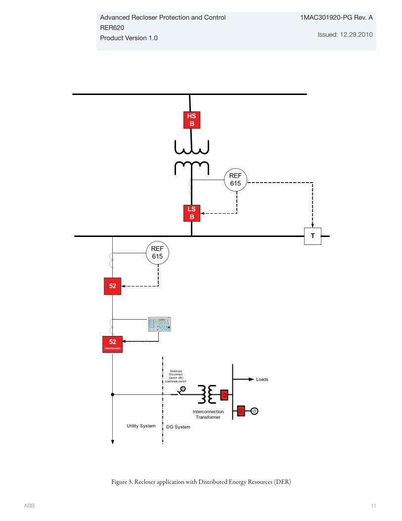
ABB 11
Advanced Recloser Protection and Control
RER620
Product Version 1.0
1MAC301920-PG Rev. A
Issued: 12.29.2010
Figure 3. Recloser application with Distributed Energy Resources (DER)
REF615
LSB
HSB
52
REF615
T
M
Motorized Disconnect Switch (89)
Load break switch
52
G
Loads
52Interconnection Transformer
Utility System DG System
52(GridShield )

ABB 12
1MAC301920-PG Rev. A
Issued: 12.29.2010
Advanced Recloser Protection and Control
RER620
Product Version 1.0
Figure 4. Recloser Loop Control
52(GridShield )
52(GridShield )
52(GridShield )
52(GridShield )
52(GridShield )
Substation Circuit
Breaker Source 1
Substation Circuit
Breaker Source 2
Sectionalizing Recloser
Midpoint Recloser
Tie Point Recloser
Sectionalizing Recloser
Midpoint Recloser
1 VT 1 VT
1 VT 1 VT
3 VT’s
3 VT’s
Normally Closed
Normally Open
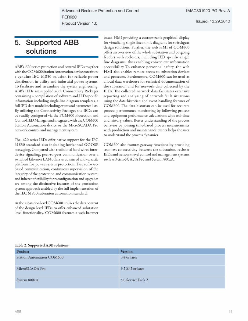
ABB 13
Advanced Recloser Protection and Control
RER620
Product Version 1.0
1MAC301920-PG Rev. A
Issued: 12.29.2010
5. Supported ABB solutions
ABB’s 620 series protection and control IEDs together with the COM600 Station Automation device constitute a genuine IEC 61850 solution for reliable power distribution in utility and industrial power systems. To facilitate and streamline the system engineering, ABB’s IEDs are supplied with Connectivity Packages containing a compilation of software and IED-specific information including single-line diagram templates, a full IED data model including event and parameter lists. By utilizing the Connectivity Packages the IEDs can be readily configured via the PCM600 Protection and Control IED Manager and integrated with the COM600 Station Automation device or the MicroSCADA Pro network control and management system.
The 620 series IEDs offer native support for the IEC 61850 standard also including horizontal GOOSE messaging. Compared with traditional hard-wired inter-device signaling, peer-to-peer communication over a switched Ethernet LAN offers an advanced and versatile platform for power system protection. Fast software-based communication, continuous supervision of the integrity of the protection and communication system, and inherent flexibility for reconfiguration and upgrades are among the distinctive features of the protection system approach enabled by the full implementation of the IEC 61850 substation automation standard.
At the substation level COM600 utilizes the data content of the design level IEDs to offer enhanced substation level functionality. COM600 features a web-browser
based HMI providing a customizable graphical display for visualizing single line mimic diagrams for switchgear design solutions. Further, the web HMI of COM600 offers an overview of the whole substation and outgoing feeders with reclosers, including IED specific single line diagrams, thus enabling convenient information accessibility To enhance personnel safety, the web HMI also enables remote access to substation devices and processes. Furthermore, COM600 can be used as a local data warehouse for technical documentation of the substation and for network data collected by the IEDs. The collected network data facilitates extensive reporting and analyzing of network fault situations using the data historian and event handling features of COM600. The data historian can be used for accurate process performance monitoring by following process and equipment performance calculations with real-time and history values. Better understanding of the process behavior by joining time-based process measurements with production and maintenance events helps the user to understand the process dynamics.
COM600 also features gateway functionality providing seamless connectivity between the substation, recloser IEDs and network-level control and management systems such as MicroSCADA Pro and System 800xA.
Table 2. Supported ABB solutions
Product VersionStation Automation COM600 3.4 or later
MicroSCADA Pro 9.2 SP2 or later
System 800xA 5.0 Service Pack 2

ABB 14
1MAC301920-PG Rev. A
Issued: 12.29.2010
Advanced Recloser Protection and Control
RER620
Product Version 1.0
COM600
Peer-to-peer GOOSE communication Peer-to-peer
GOOSE communicationIEC 61850-8-1 IEC 61850-8-1
Ethernet switch PCM600 PCM600
REM615REF615 RET615 RED615
Ethernet switch
RET615RED615 REM615 REF615 RER620RER620Fibre optic LD communication
Binary signal transfer
OPC
COM600Web HMI
COM600Web HMI
COM600
Ethernet switch
ABB System 800xA
R
69/13.8 kV60 MVA
CB
CB
69 kV
CB
R
CB
RER620
RER620
REF615 REF615
RET615
DNP3.0 - Note 2
SCADA/DMS
DNP3.0 or IEC 60870-5-104
HMI, Gateway, FDIR (Fault Detection Isolation and Restoration)
Distribution Substation
DNP3.0 (serial or TCP/IP), IEC61850-8-1
COM600
Ethernet Switch
LAN/WAN
Peer-to-peer via IEC 61850 -8-1 (Note 1)
LAN/WAN
Wireless(radio,
cellular...) IEC 60870 -5-104
DNP3.0 , IEC 60870-5-104
Note 1: Peer-to-peer over IEC61850 - GOOSE can be used for sharing information between recloser for possible restoration, interlocking, isolation etc...
Note 2: DNP3.0 (Serial or TCP/IP), IEC 60870-5-101, IEC 60870-5-104 supported
Note 3: Both DNP3.0 (Serial or TCP) toward SCADA/DMS and IEC61850 for peer-to-peer are supported simultaneously without additional cost .
CB – Circuit Breaker
R - Recloser
Wireless(radio,
cellular..)
REF615
Normally Closed
Normally Open
13.8 kVWirelessmodem
Wirelessmodem
Wirelessmodem
Figure 5. Utility distribution network example using 615, 620 series IEDs, Station Automation COM600 and MicroSCADA Pro
Figure 6. Industrial distribution network example using 615, 620 series IEDs, Station Automation COM600 and System 800xA

ABB 15
Advanced Recloser Protection and Control
RER620
Product Version 1.0
1MAC301920-PG Rev. A
Issued: 12.29.2010
6. Control
The IED offers status and control of one recloser/circuit breaker with dedicated push-buttons on the front panel local human machine interface (LHMI) for opening and closing of that recloser/breaker.
Further, the large graphical LCD of the IED’s HMI includes a single line diagram (SLD) with position indication for the relevant recloser/circuit breaker. Interlocking schemes required by the application are configured using the signal matrix or the application configuration feature of PCM600. The IED also incorporates a synchro-check function to ensure that the voltage, phase angle and frequency on either side of an open recloser/circuit breaker satisfy the conditions for safe interconnection of two networks.
Flexible remote breaker control of select-before-trip (SBO) or direct trip is also available with each of the supported DNP3.0 Level 2+, Modbus, IEC 60870-5-101, IEC 60870-5-104, and IEC 61850 communication protocols. Interlocking schemes required by the application are configured with Signal Matrix Tool (SMT) or Application Configuration Tool (ACT) in PCM600 .
7. Measurements
The IED continuously measures the phase currents, the sequence components of the currents and the residual current . In addition, the relay calculates the demand phase currents over a user-selectable pre-set time frame, and the phase unbalance value as a ratio between the negative sequence and positive sequence currents. Phase, ground and sequence voltage measurements plus power, energ y, frequency, and power factor measurements are included. The values measured can be accessed locally via the user interface on the IED front panel or remotely via the communication interface of the relay. The values can also be accessed locally or remotely using the web browser based user interface.
8. Digital fault recorder
The IED is provided with a digital fault recorder (DFR) featuring up to twelve analog and 64 binary signal channels. The analog channels record either the waveform or the trend of the currents and voltages measured.
The analog channels can be set to trigger the recording function when the measured value falls below or exceeds the set values. The binary signal channels can be set to start a recording on the rising or the falling edge of the binary signal or both. By default, the binary channels are set to record external or internal relay signals, e.g. the pickup or trip signals of the relay stages, or external blocking or control signals. Binary relay signals such as a protection pickup or trip signal, or an external relay control signal over a binary input can be set to trigger the recording. Phase and ground voltage waveforms would be available for inclusion in each digital recording. The recorded information is stored in a non-volatile memory and can be uploaded for subsequent fault analysis.
9. Event recorder
The IED includes a sequence of events recorder (SER) that logs important event activity. The non-volatile memory retains its data also in case the IED temporarily loses its auxiliary supply. The event log facilitates detailed pre and post-fault analyses of feeder faults and disturbances.
To collect sequence of events (SER) information, the relay incorporates a memory with a capacity of storing 512 event codes with associated date and time stamps. The event log facilitates detailed pre- and post-fault analyses of feeder faults and disturbances. The SER information can be accessed locally via the user interface on the relay front panel or remotely via the communication interface of the relay. The information can further be accessed, either locally or remotely, using the web-browser based user interface.

ABB 16
1MAC301920-PG Rev. A
Issued: 12.29.2010
Advanced Recloser Protection and Control
RER620
Product Version 1.0
10. Fault recorder
The IED has the capacity to store the records of 32 fault events. The records enable the user to analyze the most recent power system events. Each record includes the current, voltage and angle values, the Pickup times of the protection elements, time stamp, etc. The fault recording can be triggered by the pickup signal or the trip signal of a protection elements, or by both. The available measurement modes include DFT (Discrete Fourier Transform), RMS (Root-mean-square) and peak-to-peak.
All records are stored in a nonvolatile memory.
In addition, the maximum demand phase currents with date and time stamp are separately stored as recorded data. All 32 records are remotely retrievable via DNP3.0 Level 2+, IEC 60870-5-101, IEC 60870-5-104, and Modbus protocols and the 32 most recent fault records are retrievable and viewable using the front panel HMI, WMHI and PCM600 interfaces using the front panel HMI, web based WHMI and PCM600 interfaces.
11. Recloser/circuit-breaker condition monitoring
For continuous knowledge of the operational availability of the RER620 features, a comprehensive set of monitoring functions to supervise the IED health, the recloser/circuit breaker health is included. Everytime the recloser/breaker operates, there will be electrical and mechanical wear. Thus, the life of the recloser/circuit breaker reduces due to wearing. The wearing in the recloser/breaker depends on the tripping current, and the remaining life of the recloser/breaker is estimated from the recloser/breaker trip curve provided by the manufacturer. The remaining life is calculated separately for each phase and it is available as a monitored data value.
The recloser/breaker monitoring can include checking the wear and tear of the recloser/circuit breaker, the spring charging time of the breaker operating mechanism and the gas pressure of the breaker chambers. The IED also monitors the breaker travel time and the number of circuit breaker (CB) operations to provide basic information for scheduling CB maintenance.
12. Trip-circuit monitoring
In the case RER620 is used with a breaker, the trip-circuit monitoring continuously supervises the availability and operability of the trip circuit. It provides open-circuit monitoring both when the circuit breaker is in its closed and in its open position. It also detects loss of circuit-breaker control voltage. Local and remote indication are programmable to ensure immediate notification so the necessary steps can be established to correct before the next fault event occurs.
13. Self-diagnostics
The IED’s built-in self-diagnostics system continuously monitors the state of the IED hardware and the operation of the relay software. Any fault or malfunction detected will be used for alerting the operator. A permanent IED fault will block the protection functions of the IED to prevent incorrect relay operation.
14. Fuse failure protection
The IED includes fuse failure supervision functionality. The fuse failure supervision detects failures between the voltage measurement circuit and the IED. The failures are detected by the negative sequence based algorithm or by the delta voltage and delta current algorithm. Upon the detection of a failure the fuse failure supervision function activates an alarm and blocks voltage-dependent protection functions from unintended operation.

ABB 17
Advanced Recloser Protection and Control
RER620
Product Version 1.0
1MAC301920-PG Rev. A
Issued: 12.29.2010
15. Uninterruptable Power Supply (UPS)
The UPS board is a single board that provides backup power to the RER620 in the event that the main power source is lost. The UPS is connected to a battery that provides the power in such an event. The UPS is a separate box from the RER620. A battery is connected to the UPS and the UPS charges the battery. The UPS also tests the battery to ensure battery health.
The UPS may be powered by AC or DC. There are two builds of the UPS. One build covers the 125VDC and 120VAC range. And another build that covers the 250VDC and 240VAC range. The UPS is equipped with the ability to measure the input voltage if powered by AC. In the case the main AC supply is lost, alarm is provided locally to the local HMI as well as remotely.
The UPS has an isolated Auxiliary Power Supply for auxiliary equipment such as radios, modems, etc. The Auxiliary Power Supply has two output voltage settings, 12VDC and 24VDC.
The UPS has an integrated battery charger that is a current regulated charger. The battery voltage determines when the charger is switched off. The switch off voltage is influenced by the temperature to some degree. The battery charger may charge as high as 50 W, but this is limited by the firmware and presently set to a value less than 50 W. The output wattage varies through different portions of the charge curve. If the battery to be charged is completely discharged or close to being completely dead then only a small amount of charge current is applied to the battery. As the battery starts charging, indicated by a voltage increase, the current is increased. This method is used to prevent battery charge failure due to trying to charge a defective battery or shorted battery circuit. The UPS has a circuit that switches in 1.5 ohms, 40 W of resistance across the battery. This load is applied to the battery for 0.1 seconds. The battery’s voltage -is taken before and during this time. A comparison of the two measurements can be made and the health of the battery determined.
The UPS has embedded boost circuit for driving magnetic actuator of ABB GridShield reclosers. The output from this boost supply provides the power to operate the actuators for the GridShield family of reclosers.
The UPS makes use of its integrated temperature sensor to determine when the heater should engage. The UPS can also select to switch off the heater in the event there is no or limited input power. The heater will not be energized when operating off battery back up power. For example if a pole operation has just occurred the heater may be switch off so more available power can go into charging the boost capacitor. This circuit can conduct and switch 8 amps at 250VAC continuously.
16. Universal Power Driver (UPD)
The UPD is normally attached to three poles for control of a three-phase recloser in an electrical distribution system. Open and Close commands (local or remote) goes through six half-bridge drivers of UPD that are connected to form three independent full-bridge drive channels. The purpose of each channel is to allow current flow through magnetic actuator to be in the forward or reverse direction. The UPD is equipped with six binary inputs that are designed for reading switches (recloser and yellow handle position) located in the High Voltage Cabinet.
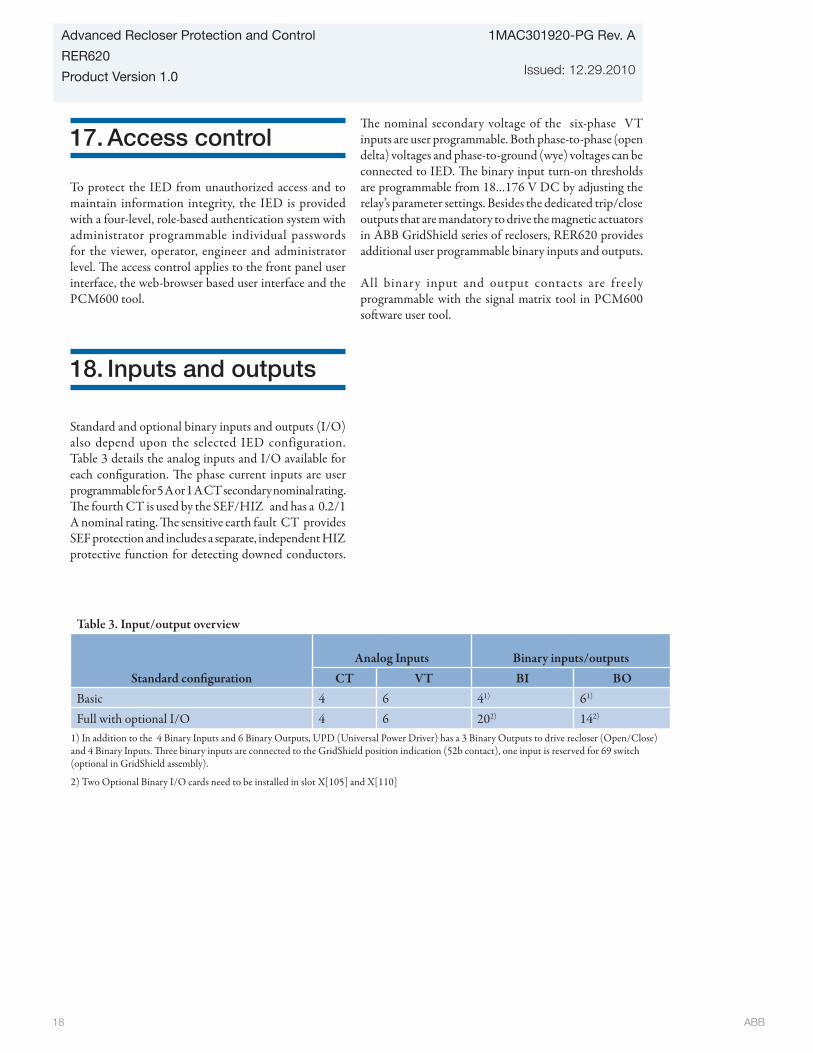
ABB 18
1MAC301920-PG Rev. A
Issued: 12.29.2010
Advanced Recloser Protection and Control
RER620
Product Version 1.0
17. Access control
To protect the IED from unauthorized access and to maintain information integrity, the IED is provided with a four-level, role-based authentication system with administrator programmable individual passwords for the viewer, operator, engineer and administrator level. The access control applies to the front panel user interface, the web-browser based user interface and the PCM600 tool.
18. Inputs and outputs
Standard and optional binary inputs and outputs (I/O) also depend upon the selected IED configuration. Table 3 details the analog inputs and I/O available for each configuration. The phase current inputs are user programmable for 5 A or 1 A CT secondary nominal rating. The fourth CT is used by the SEF/HIZ and has a 0.2/1 A nominal rating. The sensitive earth fault CT provides SEF protection and includes a separate, independent HIZ protective function for detecting downed conductors.
The nominal secondary voltage of the six-phase VT inputs are user programmable. Both phase-to-phase (open delta) voltages and phase-to-ground (wye) voltages can be connected to IED. The binary input turn-on thresholds are programmable from 18…176 V DC by adjusting the relay’s parameter settings. Besides the dedicated trip/close outputs that are mandatory to drive the magnetic actuators in ABB GridShield series of reclosers, RER620 provides additional user programmable binary inputs and outputs. All binar y input and output contacts are freely programmable with the signal matrix tool in PCM600 software user tool.
Table 3. Input/output overview
Standard configurationAnalog Inputs Binary inputs/outputs
CT VT BI BOBasic 4 6 41) 61)
Full with optional I/O 4 6 202) 142)
1) In addition to the 4 Binary Inputs and 6 Binary Outputs, UPD (Universal Power Driver) has a 3 Binary Outputs to drive recloser (Open/Close) and 4 Binary Inputs. Three binary inputs are connected to the GridShield position indication (52b contact), one input is reserved for 69 switch (optional in GridShield assembly).
2) Two Optional Binary I/O cards need to be installed in slot X[105] and X[110]

ABB 19
Advanced Recloser Protection and Control
RER620
Product Version 1.0
1MAC301920-PG Rev. A
Issued: 12.29.2010
19. Communications
The IED supports a range of different communication protocols: IEC 61850 , DNP3.0 Level 2+, IEC 60870-5-101, IEC 60870-5-104, and Modbus. Operational information and controls are available through these protocols. Unique communication functionality, for example, peer-to-peer communication between IEDs is available via the IEC 61850 communication protocol. The IEC 61850 communication implementation supports all monitoring and control functions. Additionally, parameter setting and disturbance file records can be accessed using the IEC 61850-8-1 protocol. Disturbance files are available to any Ethernet-based application in the standard COMTRADE format. Further, the IED can send and receive binary signals from other IED (peer-to-peer communication) using the IEC61850-8-1 GOOSE profile. The IED meets the GOOSE performance requirements for tripping applications in distribution substations, as defined by the IEC 61850 standard. The IED can simultaneously report events to five different clients - maximum five IEC 61850-8-1 clients, maximum five Modbus clients, maximum two clients in total for IEC 60870-5 -101 and/or IEC 60870-5-104 and maximum one DNP3.0 Level 2+client with total number not exceeding five.
All communication connectors, except for the front RJ45 connector, are located in the back of the unit on the left most card slot. This slot remains in the case when the draw out unit is removed eliminating the need to disconnect communication connections.
The relay can be connected to an Ethernet-based communications network via a copper RJ45 (100Base TX) or fiber optic LC (100Base FX) connector or serial network via the RS-485 option that provides one 4-wire or two 2-wire ports. When the IED uses the RS-485 bus for the serial communication, both two- and four wire connections are supported. Termination and pull-up/down resistors can be configured with jumpers on the communication card so external resistors are not needed.
Modbus implementation supports RTU, ASCII and TCP modes. Besides standard Modbus functionality, the IED supports retrieval of time-stamped events, changing the active setting group and uploading of the latest fault records. If a Modbus TCP connection is used, five clients can be connected to the IED simultaneously. Further, Modbus serial and Modbus TCP can be used in parallel, and if required both IEC 61850 and Modbus protocols can be run simultaneously.
Modbus over TCP/IP is supported with the Ethernet communications option selected. Besides standard Modbus functionality such as status and control operations, the relay supports retrieval of time-stamped events, uploading of disturbance files and storing of the latest fault records. For the Modbus TCP connection, a maximum of five clients can be connected to the relay simultaneously.
DNP3.0 Level 2+ over TCP/IP is also supported with the Ethernet communications card option. Another serial communications option offers programmable RS-232 or RS-485 and fiber-optic (ST) serial ports. Status and control, including recloser/breaker trip/close control, operations are supported in the Level 2+ implementation. Optional serial (RS-232/RS-485) communication interfaces are available that support user programmable protocols of DNP3.0 Level 2+, IEC 60870-5-101, and Modbus RTU/ ASCII. Another serial communications option offers programmable RS-232 or RS-485 and fiber-optic (ST) serial ports. All serial communication card options include an Ethernet communications port and an IRIG-B port for dedicated time synchronization network connections.
The companion standards IEC 60870-5-101 (for serial line) and IEC 60870-5-104 (for Ethernet) are derived from the IEC 60870-5 protocol standard definition. It specifies a functional profile for basic telecontrol tasks. The IED supports both balanced and unbalanced link mode.
The relay supports the time synchronization with a time-stamping resolution of +/-1 ms:
Ethernet based:
• SNTP (primary and secondary server support)
With special time synchronization wiring:
• IRIG-B (Inter-Range Instrumentation Group - Time Code Format B)
In addition, the IED supports time synchronization via the following serial communication protocols:• Modbus• DNP3• IEC 60870-5-103

ABB 20
1MAC301920-PG Rev. A
Issued: 12.29.2010
Advanced Recloser Protection and Control
RER620
Product Version 1.0
Table 4. Supported station communication interfaces and protocols
Interfaces/ProtocolsEthernet Serial
100BASE-TX (RJ45) 100BASE-FX (LC) RS-232/RS-485 Fiber-optic (ST) DNP3.0 Level 2+ over TCP/IP • • - - Modbus over TCP/IP • • - - IEC 61850-8-1 • • - - SNTP • • - - FTP • • - - IEC 60870-5-104 • • - - DNP3.0 Level 2+ serial - - • •Modbus RTU/ASCII - - • • IRIG-B time synchronization - - • • IEC 60870-5-101 - - • •
• = supported
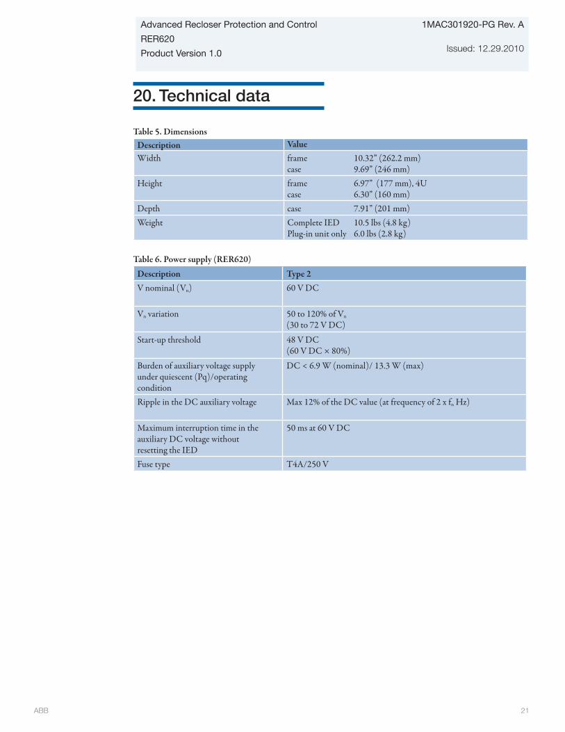
ABB 21
Advanced Recloser Protection and Control
RER620
Product Version 1.0
1MAC301920-PG Rev. A
Issued: 12.29.2010
20. Technical data
Table 6. Power supply (RER620)
Description Type 2V nominal (Vn) 60 V DC
Vn variation 50 to 120% of Vn (30 to 72 V DC)
Start-up threshold 48 V DC (60 V DC × 80%)
Burden of auxiliary voltage supplyunder quiescent (Pq)/operatingcondition
DC < 6.9 W (nominal)/ 13.3 W (max)
Ripple in the DC auxiliary voltage Max 12% of the DC value (at frequency of 2 x fn Hz)
Maximum interruption time in theauxiliary DC voltage withoutresetting the IED
50 ms at 60 V DC
Fuse type T4A/250 V
Table 5. DimensionsDescription ValueWidth frame 10.32” (262.2 mm)
case 9.69” (246 mm)Height frame 6.97” (177 mm), 4U
case 6.30” (160 mm)Depth case 7.91” (201 mm)Weight Complete IED 10.5 lbs (4.8 kg)
Plug-in unit only 6.0 lbs (2.8 kg)

ABB 22
1MAC301920-PG Rev. A
Issued: 12.29.2010
Advanced Recloser Protection and Control
RER620
Product Version 1.0
Table 8. Energizing inputsDescription ValueRated frequency 50/60 Hz ± 5 HzCurrent inputs Rated current, In 0.2/1 A1) 1/5 A2)
Thermal withstand capability:• Continuously• For 1 s
4 A100 A
20 A500 A
Dynamic current withstand:• Half-wave value 250 A 1250 AInput impedance <100 mΩ <20 mΩ
Voltage input Rated voltage 100 V AC/ 110 V AC/ 115 V AC/120 V AC (Parametrization)
Voltage withstand:• Continuous• For 10 s
2 x Vn (240 V)3 x Vn (360 V)
Burden at rated voltage <0.05 VA1) Ordering option for ground current input 2) Ground current and/or phase current
Table 9. Binary inputs
Description Value
Operating range ±20 % of the rated voltage
Rated voltage 24 to 250 V DC
Current drain 1.6 to 1.9 mA
Power consumption 31.0 to 570 mW
Threshold voltage 18 to 176 V DC
Reaction time 3 ms
Table 7. Uninterruptable Power Supply (UPS) tests
Test Type test value ReferenceControl voltage (IEEE C37.90-2005) • UPS0001 • UPS0002
90 to 150 V AC180 to 280V AC
No influence No influence
Control power interruptions (IEC 60255-11-2008) • UPS0001 and UPS0002 60 VDC 2 seconds (no battery)IEEE C37.60 - 2003 UPS0001 and UPS0002
15 kV, 27 kV, 38 kV reclosers No influence
Power consumption (IEEE C37.90-2005) • UPS0001 • UPS0002
90 to 150 VAC180 to 280 VAC
25 W (nominal)/~120 W (max)
Auxiliary Power Supply 12 VDC & 24 VDC 20 W (nominal)/~24 W (max)
Battery Charger 48 VDC 35 W maxBattery Run Time 38 hr 48 VDC 12 amp hr. battery with
standard load (15 W)Boost Supply Programmable 61-250 VDC 80 W max
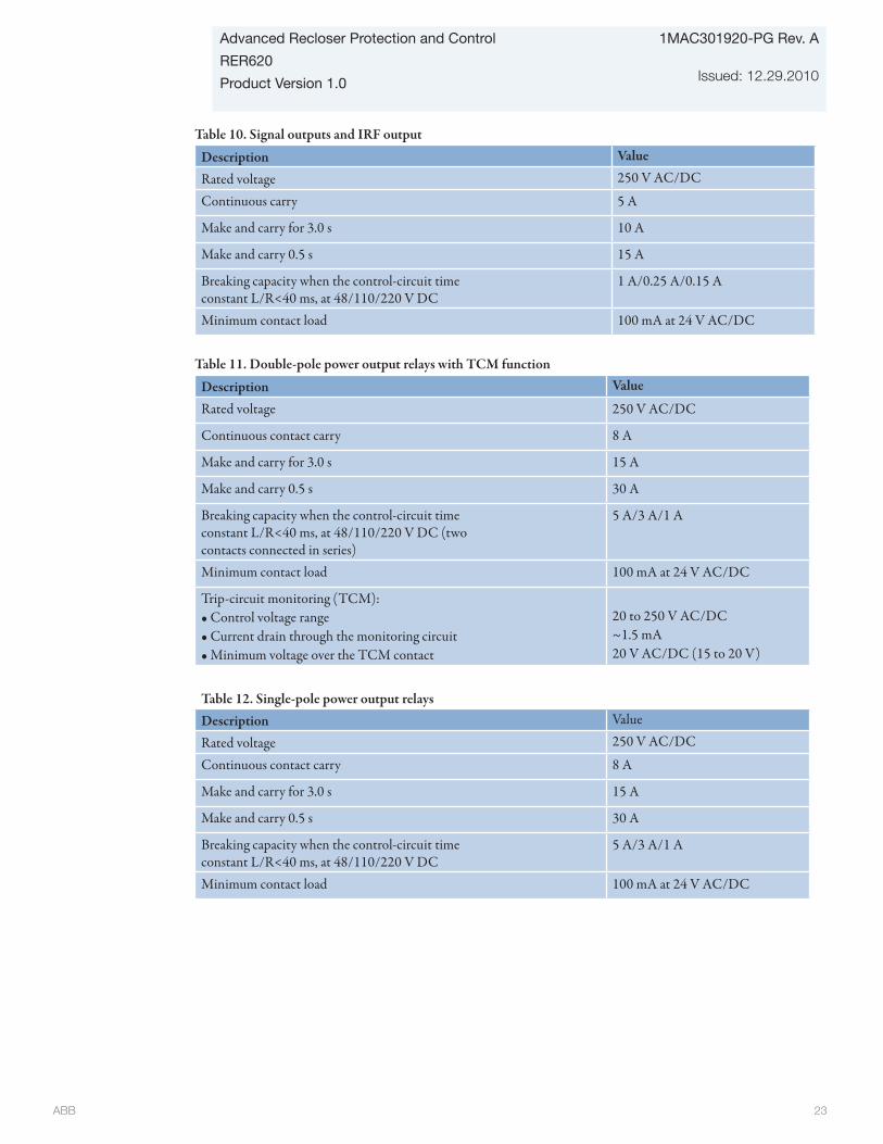
ABB 23
Advanced Recloser Protection and Control
RER620
Product Version 1.0
1MAC301920-PG Rev. A
Issued: 12.29.2010
Table 10. Signal outputs and IRF output
Description Value
Rated voltage 250 V AC/DC
Continuous carry 5 A
Make and carry for 3.0 s 10 A
Make and carry 0.5 s 15 A
Breaking capacity when the control-circuit timeconstant L/R<40 ms, at 48/110/220 V DC
1 A/0.25 A/0.15 A
Minimum contact load 100 mA at 24 V AC/DC
Table 11. Double-pole power output relays with TCM function
Description Value
Rated voltage 250 V AC/DC
Continuous contact carry 8 A
Make and carry for 3.0 s 15 A
Make and carry 0.5 s 30 A
Breaking capacity when the control-circuit timeconstant L/R<40 ms, at 48/110/220 V DC (twocontacts connected in series)
5 A/3 A/1 A
Minimum contact load 100 mA at 24 V AC/DC
Trip-circuit monitoring (TCM):• Control voltage range• Current drain through the monitoring circuit• Minimum voltage over the TCM contact
20 to 250 V AC/DC~1.5 mA20 V AC/DC (15 to 20 V)
Table 12. Single-pole power output relaysDescription Value
Rated voltage 250 V AC/DC
Continuous contact carry 8 A
Make and carry for 3.0 s 15 A
Make and carry 0.5 s 30 A
Breaking capacity when the control-circuit timeconstant L/R<40 ms, at 48/110/220 V DC
5 A/3 A/1 A
Minimum contact load 100 mA at 24 V AC/DC
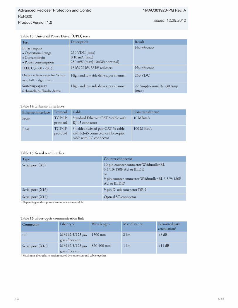
ABB 24
1MAC301920-PG Rev. A
Issued: 12.29.2010
Advanced Recloser Protection and Control
RER620
Product Version 1.0
Table 16. Fiber-optic communication link
Connector Fiber type Wave length Max distance Permitted path attenuation1
LC MM 62.5/125 μm glass fiber core
1300 mm 2 km <8 dB
Serial port (X16) MM 62.5/125 μm glass fiber core
820-900 mm 1 km <11 dB
1) Maximum allowed attenuation caused by connectors and cable together
Table 15. Serial rear interface
Type Counter connector
Serial port (X5) 10-pin counter connector Weidmuller BL 3.5/10/180F AU or BEDRor9-pin counter connector Weidmuller BL 3.5/9/180F AU or BEDR1
Serial port (X16) 9-pin D-sub conenctor DE-9
Serial port (X12) Optical ST-connector1) Depending on the optional communication module
Table 14. Ethernet interfaces
Ethernet interface Protocol Cable Data transfer rate
Front TCP/IP protocol
Standard Ethernet CAT 5 cable with RJ-45 connector
10 MBits/s
Rear TCP/IP protocol
Shielded twisted pair CAT 5e cable with RJ-45 connector or fiber-optic cable with LC connector
100 MBits/s
Table 13. Universal Power Driver (UPD) tests
Test Description Result
Binary inputs • Operational range • Current drain • Power consumption
250 VDC (max)0.10 mA (max)250 mW (max) 10mW(nominal)
No influence
IEEE C37.60 - 2003 15 kV, 27 kV, 38 kV reclosers No influence
Output voltage range for 6 chan-nels, half bridge drivers
High and low side drives, per channel 250 VDC
Switching capacity 6 channels, half bridge drivers
High and low side drives, per channel 22 Amp(nominal)/~30 Amp (max)
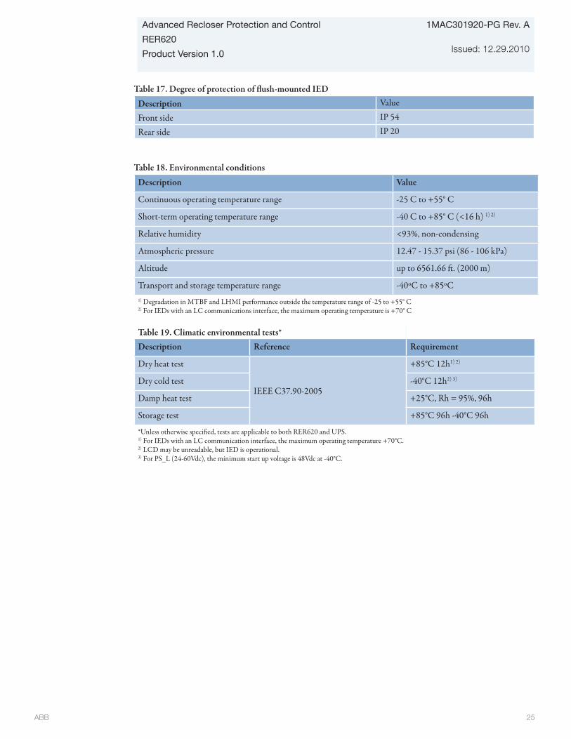
ABB 25
Advanced Recloser Protection and Control
RER620
Product Version 1.0
1MAC301920-PG Rev. A
Issued: 12.29.2010
Table 18. Environmental conditions
Description Value
Continuous operating temperature range -25 C to +55° C
Short-term operating temperature range -40 C to +85° C (<16 h) 1) 2)
Relative humidity <93%, non-condensing
Atmospheric pressure 12.47 - 15.37 psi (86 - 106 kPa)
Altitude up to 6561.66 ft. (2000 m)
Transport and storage temperature range -40ºC to +85ºC1) Degradation in MTBF and LHMI performance outside the temperature range of -25 to +55° C2) For IEDs with an LC communications interface, the maximum operating temperature is +70° C
Table 19. Climatic environmental tests*Description Reference Requirement
Dry heat test
IEEE C37.90-2005
+85°C 12h1) 2)
Dry cold test -40°C 12h2) 3)
Damp heat test +25°C, Rh = 95%, 96h
Storage test +85°C 96h -40°C 96h
*Unless otherwise specified, tests are applicable to both RER620 and UPS.1) For IEDs with an LC communication interface, the maximum operating temperature +70°C.2) LCD may be unreadable, but IED is operational.3) For PS_L (24-60Vdc), the minimum start up voltage is 48Vdc at -40°C.
Table 17. Degree of protection of flush-mounted IED
Description Value
Front side IP 54
Rear side IP 20
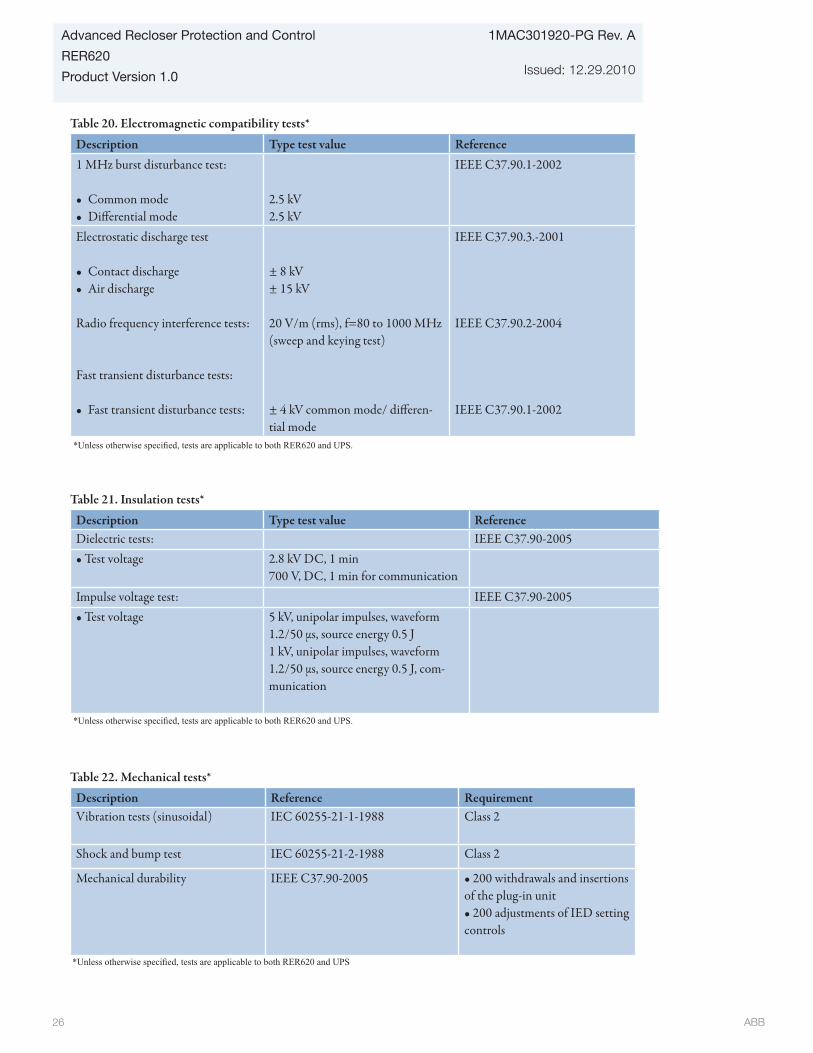
ABB 26
1MAC301920-PG Rev. A
Issued: 12.29.2010
Advanced Recloser Protection and Control
RER620
Product Version 1.0
Table 21. Insulation tests*
Description Type test value ReferenceDielectric tests: IEEE C37.90-2005 • Test voltage 2.8 kV DC, 1 min
700 V, DC, 1 min for communication Impulse voltage test: IEEE C37.90-2005 • Test voltage 5 kV, unipolar impulses, waveform
1.2/50 μs, source energy 0.5 J 1 kV, unipolar impulses, waveform 1.2/50 μs, source energy 0.5 J, com-munication
Table 22. Mechanical tests*
Description Reference RequirementVibration tests (sinusoidal) IEC 60255-21-1-1988 Class 2
Shock and bump test IEC 60255-21-2-1988 Class 2
Mechanical durability IEEE C37.90-2005 • 200 withdrawals and insertions of the plug-in unit • 200 adjustments of IED setting controls
*Unless otherwise specified, tests are applicable to both RER620 and UPS.
*Unless otherwise specified, tests are applicable to both RER620 and UPS
Table 20. Electromagnetic compatibility tests*
Description Type test value Reference1 MHz burst disturbance test:
• Common mode• Differential mode
2.5 kV 2.5 kV
IEEE C37.90.1-2002
Electrostatic discharge test
• Contact discharge• Air discharge
Radio frequency interference tests:
Fast transient disturbance tests:
• Fast transient disturbance tests:
± 8 kV ± 15 kV
20 V/m (rms), f=80 to 1000 MHz (sweep and keying test)
± 4 kV common mode/ differen-tial mode
IEEE C37.90.3.-2001
IEEE C37.90.2-2004
IEEE C37.90.1-2002
*Unless otherwise specified, tests are applicable to both RER620 and UPS.

ABB 27
Advanced Recloser Protection and Control
RER620
Product Version 1.0
1MAC301920-PG Rev. A
Issued: 12.29.2010
Protection functions
Table 23. 51P/50P technical data
Characteristic Value
Depending on the frequency of the current measured: fn ±2Hz
Operation accuracy 51P ±1.5% of the set value or ±0.002 x In
50P-1, 50P-2and50P-3
±1.5% of set value or ±0.002 x In
(at currents in the range of 0.1…10 x In)±5.0% of the set value(at currents in the range of 10…40 x In)
Pickup time 1) 2) Minimum Typical Maximum50P-3:IFault = 2 x set Pickup valueIFault = 10 x set Pickup value
16 ms11 ms
19 ms12 ms
23 ms14 ms
51P and 50P-1/2:IFault = 2 x set Pickup range 22 ms 24 ms 25 ms
Reset time < 40 msReset ratio Typical 0.96Retardation time < 30 msTrip time accuracy in definite time mode ±1.0% of the set value or ±20 msTrip time accuracy in inverse time mode ±5.0% of the theoretical value or ±20 ms 3)
Suppression of harmonics RMS: No suppression DFT: -50dB at f = n x fn, where n = 2, 3, 4, 5,…Peak-to-Peak: No suppressionP-to-P+backup: No suppression
1) Set Operate delay time = 0,02 s, Operate curve type = ANSI definite time, Measurement mode = default (depends on stage), current before fault = 0.0 x In, fn = 50 Hz, fault current in one phase with nominal frequency injected from random phase angle, results based on statistical distribution of 1000 measurements
2) Includes the delay of the signal output contact3) Maximum Pickup range = 2.5 x In, Pickup range multiples in range of 1.5 to 20
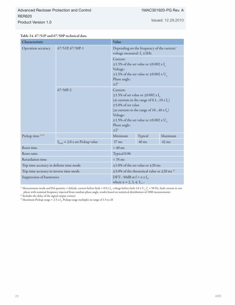
ABB 28
1MAC301920-PG Rev. A
Issued: 12.29.2010
Advanced Recloser Protection and Control
RER620
Product Version 1.0
Table 24. 67/51P and 67/50P technical data
Characteristic Value
Operation accuracy 67/51P, 67/50P-1 Depending on the frequency of the current/voltage measured: fn ±2HzCurrent:±1.5% of the set value or ±0.002 x In
Voltage: ±1.5% of the set value or ±0.002 x Un
Phase angle:±2°
67/50P-2 Current:±1.5% of set value or ±0.002 x In
(at currents in the range of 0.1…10 x In)±5.0% of set value(at currents in the range of 10…40 x In)Voltage:±1.5% of the set value or ±0.002 x Un
Phase angle:±2°
Pickup time 1) 2) Minimum Typical MaximumIFault = 2.0 x set Pickup value 37 ms 40 ms 42 ms
Reset time < 40 msReset ratio Typical 0.96Retardation time < 35 msTrip time accuracy in definite time mode ±1.0% of the set value or ±20 msTrip time accuracy in inverse time mode ±5.0% of the theoretical value or ±20 ms 3)
Suppression of harmonics DFT: -50dB at f = n x fn, where n = 2, 3, 4, 5,…-
1) Measurement mode and Pol quantity = default, current before fault = 0.0 x In, voltage before fault 1.0 x Un, fn = 50 Hz, fault current in one phase with nominal frequency injected from random phase angle, results based on statistical distribution of 1000 measurements
2) Includes the delay of the signal output contact3) Maximum Pickup range = 2.5 x In, Pickup range multiples in range of 1.5 to 20
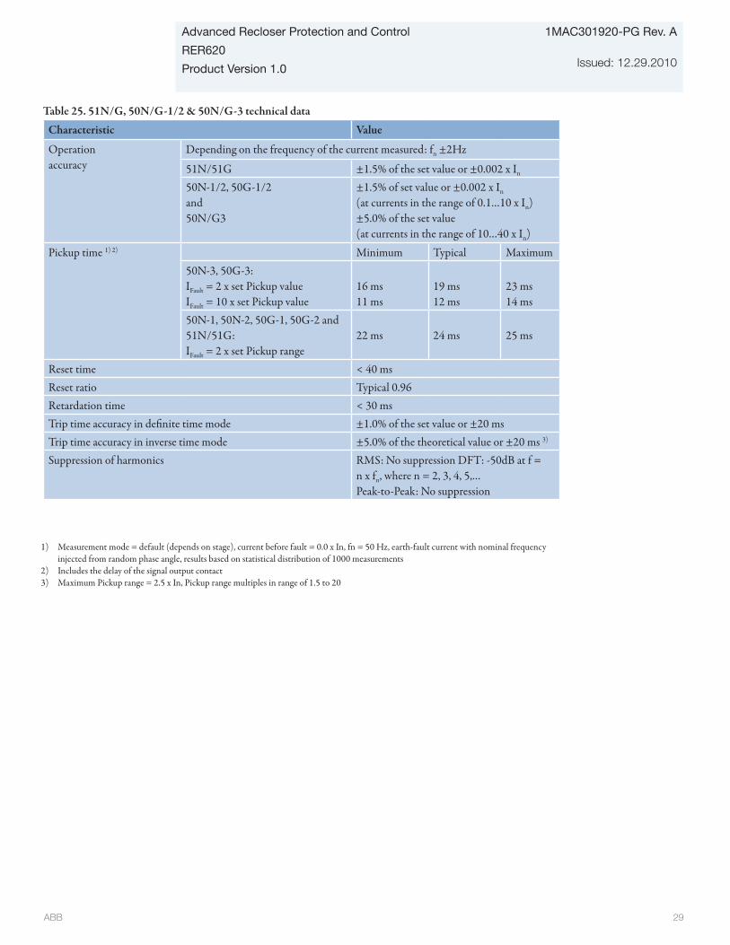
ABB 29
Advanced Recloser Protection and Control
RER620
Product Version 1.0
1MAC301920-PG Rev. A
Issued: 12.29.2010
Table 25. 51N/G, 50N/G-1/2 & 50N/G-3 technical data
Characteristic Value
Operation accuracy
Depending on the frequency of the current measured: fn ±2Hz
51N/51G ±1.5% of the set value or ±0.002 x In
50N-1/2, 50G-1/2 and50N/G3
±1.5% of set value or ±0.002 x In
(at currents in the range of 0.1…10 x In)±5.0% of the set value(at currents in the range of 10…40 x In)
Pickup time 1) 2) Minimum Typical Maximum50N-3, 50G-3:IFault = 2 x set Pickup valueIFault = 10 x set Pickup value
16 ms11 ms
19 ms12 ms
23 ms14 ms
50N-1, 50N-2, 50G-1, 50G-2 and 51N/51G:IFault = 2 x set Pickup range
22 ms 24 ms 25 ms
Reset time < 40 msReset ratio Typical 0.96Retardation time < 30 msTrip time accuracy in definite time mode ±1.0% of the set value or ±20 msTrip time accuracy in inverse time mode ±5.0% of the theoretical value or ±20 ms 3)
Suppression of harmonics RMS: No suppression DFT: -50dB at f = n x fn, where n = 2, 3, 4, 5,…Peak-to-Peak: No suppression
1) Measurement mode = default (depends on stage), current before fault = 0.0 x In, fn = 50 Hz, earth-fault current with nominal frequency injected from random phase angle, results based on statistical distribution of 1000 measurements
2) Includes the delay of the signal output contact3) Maximum Pickup range = 2.5 x In, Pickup range multiples in range of 1.5 to 20

ABB 30
1MAC301920-PG Rev. A
Issued: 12.29.2010
Advanced Recloser Protection and Control
RER620
Product Version 1.0
Table 26. 67/51N and 67/50N technical dataCharacteristic Value
Operation accuracy
67/51N, 67/50N-1 Depending on the frequency of the current mea-sured: fn ±2HzCurrent: ±1.5% of the set value or ±0.002 x In
Voltage: ±1.5% of the set value or ±0.002 x Vn
Phase angle: ±2°
67N/50N-2 Current: ±1.5% of the set value or ±0.002 x In (at currents in the range of 0.1…10 x In)
±5.0% of the set value (at currents in the range of 10…40 x In)
Voltage:±1.5% of the set value or ±0.002 x Vn
Phase angle:±2°
Pickup time 1) 2) Minimum Typical Maximum67N/51N, 67N/50N-1 and 67N/50N-2:IFault = 2 x set Pickup range 61 ms 64 ms 66 ms
Reset time < 40 msReset ratio Typical 0.96Retardation time < 30 msTrip time accuracy in definite time mode ±1.0% of the set value or ±20 msTrip time accuracy in inverse time mode ±5.0% of the theoretical value or ±20 ms 3)
Suppression of harmonics RMS: No suppression DFT: -50dB at f = n x fn, where n = 2, 3, 4, 5,…Peak-to-Peak: No suppression
1) Set Definite time delay = 0,06 s, Inverse-time (IDMT) and definite-time (DT) curves = ANSI definite time, Measurement mode = default (depends on stage), current before fault = 0.0 x In, fn = 50 Hz, earth-fault current with nominal frequency injected from random phase angle, results based on statistical distribution of 1000 measurements
2) Includes the delay of the signal output contact3) Maximum Pickup range = 2.5 x In, Pickup range multiples in range of 1.5 to 20

ABB 31
Advanced Recloser Protection and Control
RER620
Product Version 1.0
1MAC301920-PG Rev. A
Issued: 12.29.2010
Table 27. 46 technical data
Characteristic ValueOperation accuracy
Depending on the frequency of the current measured: fn ±2Hz±1.5% of the set value or ±0.002 x In
Pickup time 1) 2)
IFault = 2 x set Pickup valueIFault = 10 x set Pickup value
Minimum Typical Maximum22 ms14 ms
24 ms16 ms
25 ms17 ms
Reset time < 40 msReset ratio Typical 0.96Retardation time < 35 msTrip time accuracy in definite time mode ±1.0% of the set value or ±20 msTrip time accuracy in inverse time mode ±5.0% of the theoretical value or ±20 ms 3)
Suppression of harmonics DFT: -50dB at f = n x fn, where n = 2, 3, 4, 5,…
1) Negative sequence voltage before fault 0.0 x Un, fn = 50 Hz, negative sequence overvoltage with nominal frequency injected from random phase angle, results based on statistical distribution of 1000 measurements
2) Includes the delay of the signal output contact 3) Maximum Pickup value = 2.5 x In, Pickup value multiples in range of 1.5 to 20
Table 29. Three-phase inrush current detection (INR)
Characteristic ValuePickup Accuracy At the frequency f=fn
Current measurement: ±1.5% of set value or ±0.002 x InRatio I2f/I1f measurement: ±5.0% of set value
Reset time +35 ms / -0 msReset ratio Typical 0.96Trip time accuracy +35 ms / -0 ms
Table 28. 46PD technical data
Characteristic ValueOperation accuracy Depending on the frequency of the current
measured: fn ±2Hz±2% of the set value
Pickup time < 70 msReset time < 40 msReset ratio Typical 0.96Retardation time < 35 msTrip time accuracy in definite time mode ±1.0% of the set value or ±20 msSuppression of harmonics DFT: -50dB at f = n x fn, where n = 2, 3, 4, 5,…
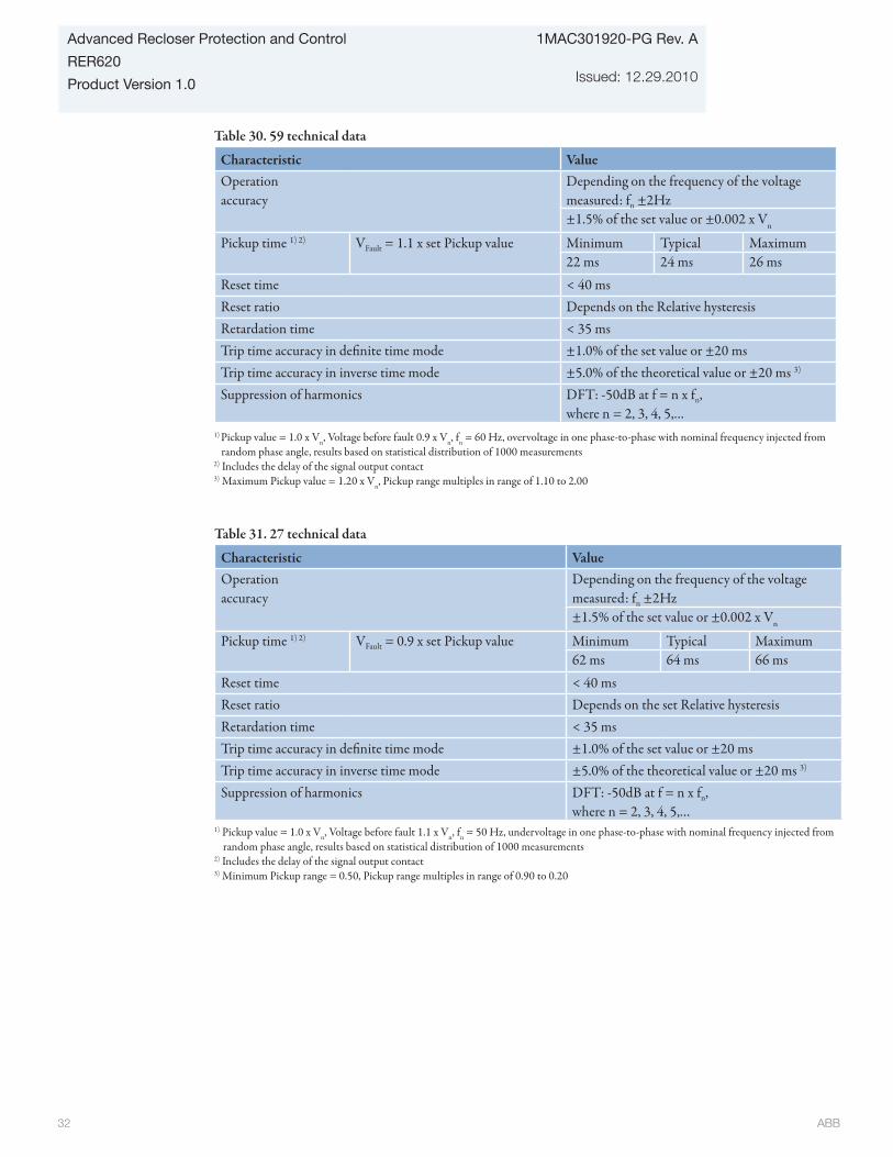
ABB 32
1MAC301920-PG Rev. A
Issued: 12.29.2010
Advanced Recloser Protection and Control
RER620
Product Version 1.0
Table 30. 59 technical data
Characteristic ValueOperation accuracy
Depending on the frequency of the voltage measured: fn ±2Hz±1.5% of the set value or ±0.002 x Vn
Pickup time 1) 2) VFault = 1.1 x set Pickup value Minimum Typical Maximum22 ms 24 ms 26 ms
Reset time < 40 msReset ratio Depends on the Relative hysteresisRetardation time < 35 msTrip time accuracy in definite time mode ±1.0% of the set value or ±20 msTrip time accuracy in inverse time mode ±5.0% of the theoretical value or ±20 ms 3)
Suppression of harmonics DFT: -50dB at f = n x fn, where n = 2, 3, 4, 5,…
1) Pickup value = 1.0 x Vn, Voltage before fault 0.9 x Vn, fn = 60 Hz, overvoltage in one phase-to-phase with nominal frequency injected from random phase angle, results based on statistical distribution of 1000 measurements
2) Includes the delay of the signal output contact3) Maximum Pickup value = 1.20 x Vn, Pickup range multiples in range of 1.10 to 2.00
Table 31. 27 technical data
Characteristic ValueOperation accuracy
Depending on the frequency of the voltage measured: fn ±2Hz±1.5% of the set value or ±0.002 x Vn
Pickup time 1) 2) VFault = 0.9 x set Pickup value Minimum Typical Maximum62 ms 64 ms 66 ms
Reset time < 40 msReset ratio Depends on the set Relative hysteresisRetardation time < 35 msTrip time accuracy in definite time mode ±1.0% of the set value or ±20 msTrip time accuracy in inverse time mode ±5.0% of the theoretical value or ±20 ms 3)
Suppression of harmonics DFT: -50dB at f = n x fn, where n = 2, 3, 4, 5,…
1) Pickup value = 1.0 x Vn, Voltage before fault 1.1 x Vn, fn = 50 Hz, undervoltage in one phase-to-phase with nominal frequency injected from random phase angle, results based on statistical distribution of 1000 measurements
2) Includes the delay of the signal output contact3) Minimum Pickup range = 0.50, Pickup range multiples in range of 0.90 to 0.20

ABB 33
Advanced Recloser Protection and Control
RER620
Product Version 1.0
1MAC301920-PG Rev. A
Issued: 12.29.2010
Table 33. 47 technical data
Characteristic Value
Operation accuracy Depending on the frequency of the voltage measured: fn ±2Hz±1.5% of the set value or ±0.002 x Un
Pickup time 1) 2) Minimum Typical MaximumVFault = 1.1 x set Pickup value 33 ms 35 ms 37 msVFault = 2.0 x set Pickup value 24 ms 26 ms 28 ms
Reset time < 40 msReset ratio Typical 0.96Retardation time < 35 msTrip time accuracy in definite time mode ±1.0% of the set value or ±20 msSuppression of harmonics DFT: -50dB at f = n x fn, where n = 2, 3, 4, 5,…
1) Negative sequence voltage before fault 0.0 x Un, fn = 50 Hz, negative sequence overvoltage with nominal frequency injected from random phase angle, results based on statistical distribution of 1000 measurements
2) Includes the delay of the signal output contact
Table 32. 59G technical data
Characteristic ValueOperationaccuracy
Depending on the frequency of the voltage measured: fn ±2Hz±1.5% of the set value or ±0.002 x Vn
Pickup time 1) 2) Minimum Typical MaximumVFault = 1.1 x set Pickup value 29 ms 31 ms 32 ms
Reset time < 40 msReset ratio Typical 0.96Retardation time < 35 msTrip time accuracy in definite time mode ±1.0% of the set value or ±20 msSuppression of harmonics DFT: -50dB at f = n x fn, where n = 2, 3, 4, 5,…
1) Ground voltage before fault 0.0 x Vn, fn = 50 Hz, residual voltage with nominal frequency injected from random phase angle, results based on statistical distribution of 1000 measurements
2) Includes the delay of the signal output contact

ABB 34
1MAC301920-PG Rev. A
Issued: 12.29.2010
Advanced Recloser Protection and Control
RER620
Product Version 1.0
Table 34. FRPFRQ technical dataCharacteristic ValueOperation accuracy f< ±10 Hz
df/dt ±100 mHz/s (in range |df/dt| < 5 Hz/s)±2.0% of the set value (in range 5 Hz/s < | df/dt| < 15 Hz/s)
Start time f>/f< < 80 msdf/dt < 120 ms
Reset time < 150 msOperate time accuracy ±1.0% of the set value or ±30 ms
Table 35. 81S technical dataCharacteristic ValueOperation accuracy f< ±10 Hz
df/dt ±100 mHz/s (in range |df/dt| < 5 Hz/s)±2.0% of the set value (in range 5 Hz/s < | df/dt| < 15 Hz/s)
Start time f< < 80 msdf/dt < 120 ms
Reset time < 150 msOperate time accuracy ±1.0% of the set value or ±30 ms
Table 36. 50BF technical dataCharacteristic ValueOperation accuracy Depending on the frequency of the voltage mea-
sured: fn ±2Hz±1.5% of the set value or ±0.002 x In
Trip time accuracy ±1.0% of the set value or ±20 ms

ABB 35
Advanced Recloser Protection and Control
RER620
Product Version 1.0
1MAC301920-PG Rev. A
Issued: 12.29.2010
Measurement functions
Table 37. IA, IB, IC technical data
Characteristic Value
Operation accuracy
Depending on the frequency of the current measured: fn ±2Hz
±0.5% or ±0.002 x In
(at currents in the range of 0.01 to 4.00 x In)Suppression of harmonics
DFT: -50dB at f = n x fn, where n = 2, 3, 4, 5,…RMS: No suppression
Table 38. VA, VB, VC
Characteristic Value
Operation accuracy
Depending on the frequency of the current measured: fn ±2HzAt voltages in range 0.01 to 4.00 x In
±0.5% or ±0.002 x Vn
Suppression of harmonics
DFT: -50dB at f = n x fn, where n = 2, 3, 4, 5,…RMS: No suppression
Table 39. IG technical data
Characteristic Value
Operation accuracy
Depending on the frequency of the current measured: f/fn = ±2Hz
±0.5% or ±0.002 x In
at currents in the range of 0.01 to 4.00 x In
Suppression of harmonics
DFT: -50dB at f = n x fn, where n = 2, 3, 4, 5,…RMS: No suppression
Table 40. VG technical data
Characteristic Value
Operation accuracy
Depending on the frequency of the current measured: f/fn = ±2Hz
±0.5% or ±0.002 x Vn
Suppression of harmonics
DFT: -50dB at f = n x fn, where n = 2, 3, 4, 5,…RMS: No suppression
Table 41. I1, I2, I0 technical data
Characteristic Value
Operation accuracy
Depending on the frequency of the current measured: f/fn = ±2Hz
±1.0% or ±0.002 x In
at currents in the range of 0.01 to 4.00 x In
Suppression of harmonics
DFT: -50dB at f = n x fn, where n = 2, 3, 4, 5,…

ABB 36
1MAC301920-PG Rev. A
Issued: 12.29.2010
Advanced Recloser Protection and Control
RER620
Product Version 1.0
Table 42. V1, V2, V0 technical data
Characteristic Value
Operation accuracy
Depending on the frequency of the current measured: f/fn = ±2HzAt voltages in range 0.01 to 4.00 x In
±1.0% or ±0.002 x Vn
Suppression of harmonics
DFT: -50dB at f = n x fn, where n = 2, 3, 4, 5,…
Table 44. FMMXU technical data
Characteristic Value
Operation accuracy
±10 mHz (in measurement range 35-75 Hz)
Table 43. P, E technical data
Characteristic Value
Operation accuracy
At all three currents in range 0.10 to 1.20 x In
At all three voltages in range 0.50 to 1.15 x Vn
At the frequency fn = ±1HzActive power and energy in range |PF| > 0.71Reactive power and energy in range |PF| < 0.71±1.5% for power (S, P and Q)±0.015% for power factor±1.5% for energy
Suppression of harmonics
DFT: -50dB at f = n x fn, where n = 2, 3, 4, 5,…
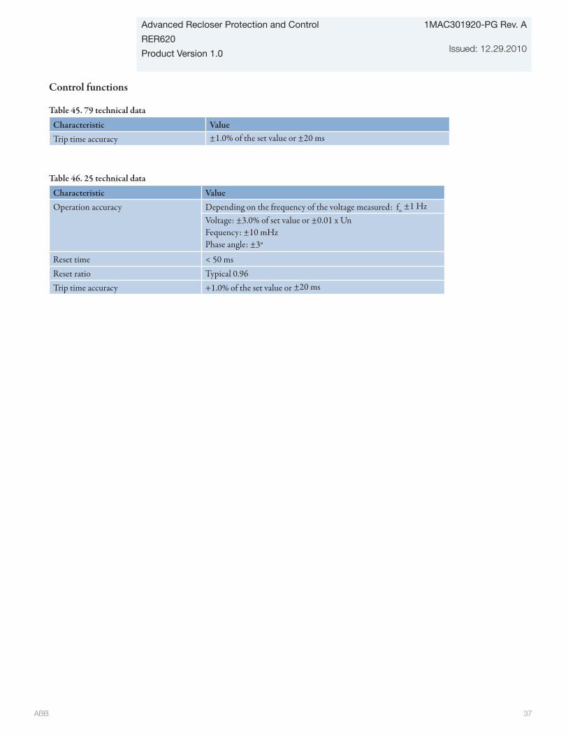
ABB 37
Advanced Recloser Protection and Control
RER620
Product Version 1.0
1MAC301920-PG Rev. A
Issued: 12.29.2010
Control functions
Table 45. 79 technical data
Characteristic ValueTrip time accuracy ±1.0% of the set value or ±20 ms
Table 46. 25 technical data
Characteristic ValueOperation accuracy Depending on the frequency of the voltage measured: fn ±1 Hz
Voltage: ±3.0% of set value or ±0.01 x UnFequency: ±10 mHzPhase angle: ±3°
Reset time < 50 msReset ratio Typical 0.96Trip time accuracy +1.0% of the set value or ±20 ms
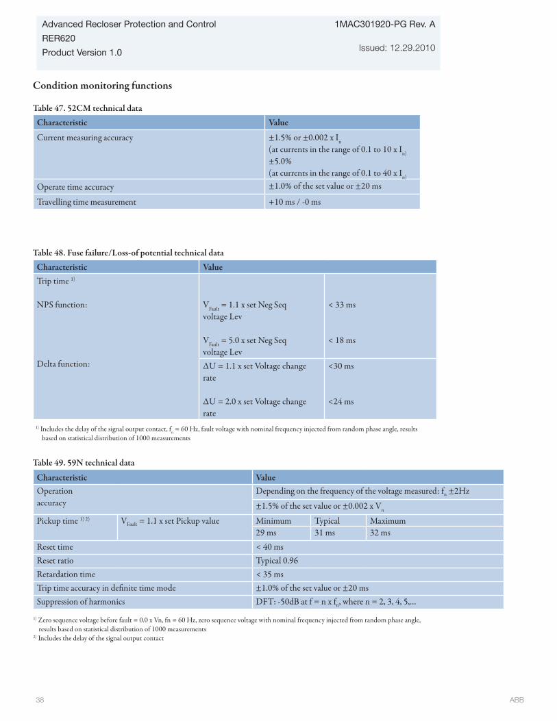
ABB 38
1MAC301920-PG Rev. A
Issued: 12.29.2010
Advanced Recloser Protection and Control
RER620
Product Version 1.0
Condition monitoring functions
Table 47. 52CM technical data
Characteristic Value
Current measuring accuracy ±1.5% or ±0.002 x In
(at currents in the range of 0.1 to 10 x In)
±5.0%(at currents in the range of 0.1 to 40 x In)
Operate time accuracy ±1.0% of the set value or ±20 ms
Travelling time measurement +10 ms / -0 ms
Table 48. Fuse failure/Loss-of potential technical data
Characteristic ValueTrip time 1)
NPS function:
Delta function:
VFault = 1.1 x set Neg Seq voltage Lev
VFault = 5.0 x set Neg Seq voltage Lev
< 33 ms
< 18 ms
∆U = 1.1 x set Voltage change rate
∆U = 2.0 x set Voltage change rate
<30 ms
<24 ms
1) Includes the delay of the signal output contact, fn = 60 Hz, fault voltage with nominal frequency injected from random phase angle, results based on statistical distribution of 1000 measurements
Table 49. 59N technical data
Characteristic ValueOperation accuracy
Depending on the frequency of the voltage measured: fn ±2Hz
±1.5% of the set value or ±0.002 x Vn
Pickup time 1) 2) VFault = 1.1 x set Pickup value Minimum Typical Maximum29 ms 31 ms 32 ms
Reset time < 40 msReset ratio Typical 0.96Retardation time < 35 msTrip time accuracy in definite time mode ±1.0% of the set value or ±20 msSuppression of harmonics DFT: -50dB at f = n x fn, where n = 2, 3, 4, 5,…
1) Zero sequence voltage before fault = 0.0 x Vn, fn = 60 Hz, zero sequence voltage with nominal frequency injected from random phase angle, results based on statistical distribution of 1000 measurements
2) Includes the delay of the signal output contact

ABB 39
Advanced Recloser Protection and Control
RER620
Product Version 1.0
1MAC301920-PG Rev. A
Issued: 12.29.2010
Table 50. 59PS technical data
Characteristic ValueOperation accuracy
Depending on the frequency of the voltage measured: fn ±2Hz
±1.5% of the set value or ±0.002 x Vn
Pickup time 1) 2) VFault = 1.1 x set Pickup value Minimum Typical Maximum29 ms 31 ms 32 ms
Reset time < 40 msReset ratio Typical 0.96Retardation time < 35 msTrip time accuracy in definite time mode ±1.0% of the set value or ±20 msSuppression of harmonics DFT: -50dB at f = n x fn, where n = 2, 3, 4, 5,…
1) Zero sequence voltage before fault = 0.0 x Vn, fn = 60 Hz, zero sequence voltage with nominal frequency injected from random phase angle, results based on statistical distribution of 1000 measurements
2) Includes the delay of the signal output contact
Table 51. 32P technical data
Characteristic ValueOperation accuracy Depending on the frequency of the voltage measured: fn ±2 Hz
±1.5% of the current or ±0.01A±1.5% of the voltage or ±1V±3.0% of the characteristic angle or ±4 Deg
Table 52. 32N technical data
Characteristic ValueOperation accuracy Depending on the frequency of the voltage measured: fn ±2 Hz
±1.5% of the current or ±0.01A±1.5% of the voltage or ±1V±3.0% of the characteristic angle or ±4 Deg
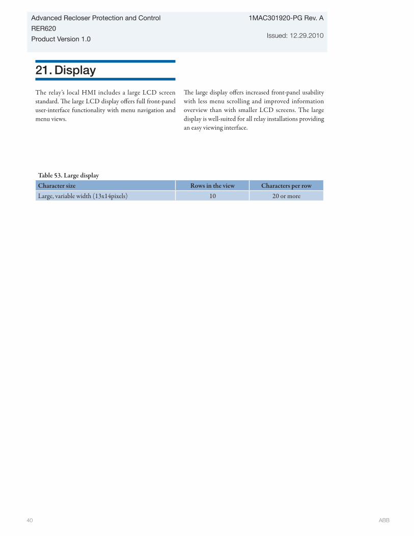
ABB 40
1MAC301920-PG Rev. A
Issued: 12.29.2010
Advanced Recloser Protection and Control
RER620
Product Version 1.0
21. Display
The relay’s local HMI includes a large LCD screen standard. The large LCD display offers full front-panel user-interface functionality with menu navigation and menu views.
The large display offers increased front-panel usability with less menu scrolling and improved information overview than with smaller LCD screens. The large display is well-suited for all relay installations providing an easy viewing interface.
Table 53. Large displayCharacter size Rows in the view Characters per rowLarge, variable width (13x14pixels) 10 20 or more

ABB 41
Advanced Recloser Protection and Control
RER620
Product Version 1.0
1MAC301920-PG Rev. A
Issued: 12.29.2010
22. Local HMI
The IED’s local HMI includes a large LCD screen standard. The large LCD display offers full front-panel user-interface functionality with menu navigation and menu views. The large display offers increased front-panel usability with less menu scrolling and improved information overview than with smaller LCD screens. In addition, the large display includes a user configurable single line diagram (SLD) with position indication for the associated primary equipment. The standard configuration of the IED displays, apart from the primary equipment position, the related measuring values. Thus all necessary measurement can be viewed without scrolling through the IED menu. The SLD view can also be accessed using the web-browser baser user interface. The default SLD can be modified according to user requirements using the graphical display editor in PCM600.
The local HMI includes a push button (L/R) for local/remote operation of the IED. When the IED is in local mode the IED can only be operated using the local front panel user interface. When the IED is in remote mode the IED can execute commands sent from a remote location. The IED supports the remote selection of local/remote mode via a binary input. This feature facilitates, for example, the use of an external switch at the substation to ensure that all IEDs are in local mode during maintenance work and that the recloser/circuit breakers cannot be operated remotely from the network control centre.
The large display is well-suited for all IED’s installations providing an easy viewing interface.
The IED provides sixteen user configurable push buttons that are used for easy and quick operations, thus eliminating need for traditional external control switches. These pushbuttons are accessible in the RER620 for making any user defined logic. For each push button different operation modes such as pulsed, toggled are available. Each push button includes imbedded LED and configuration labels template is provided.
By eleven user config urable LEDs, traditional annunciation panel can be replaced. The input signal for each LED is selected individually with the PCM 600 Signal Matrix Tool (SMT). Each indication LED on the IED can be set individually to operate in four different sequences (based on application): two as follow type and two as latch type. The light from the LEDs can be steady or flickering. LED label template is provided to suit your control scheme.

ABB 42
1MAC301920-PG Rev. A
Issued: 12.29.2010
Advanced Recloser Protection and Control
RER620
Product Version 1.0
Fig. 7: Large display standard

ABB 43
Advanced Recloser Protection and Control
RER620
Product Version 1.0
1MAC301920-PG Rev. A
Issued: 12.29.2010
23. Mounting methodsBy means of appropriate mounting accessories the standard relay case for the 620 series relays can be flush mounted, semi-flush mounted or wall mounted. The RER620 can be only flush mounted. Further, the relays can be mounted in any standard 19” instrument cabinet by means of 19” mounting panels available with cut-outs for one or two relays. For the routine testing purposes, the relay cases can be equipped with ABB Flexitest (FT) test switches, type FT-1 or FT-19R, which can be mounted side by side or below the relay cases.
Mounting methods:• Flush mounting• Mounting with Flexitest (FT) test switches to a 19”rack
Requirements for installation: • Panel cut-out of 9.76 x 6.38 inches (248 x 162 mm) • Depth behind the panel 6.02 inches (153 mm)
24. IED case and drawout unit
For safety reasons, the IED cases are provided with automatically operating contacts for short-circuiting the CT secondary circuits when a IED unit is withdrawn from its case. The IED case is further provided with a mechanical coding system preventing current measuring relay units from being inserted into a relay case for a voltage measuring relay unit and vice versa, i.e. the relay cases are assigned to a certain type of relay draw-out unit.
Figure 8: Flush mounting a case into a panel cut-out
A 9.76 inches (248±1 mm)B 6.38 inches (162±1 mm)
Fixing screws
B
A

ABB 44
1MAC301920-PG Rev. A
Issued: 12.29.2010
Advanced Recloser Protection and Control
RER620
Product Version 1.0
25. Selection and ordering data
The relay type and serial number label identifies the protection IED . The label is placed above the HMI on the upper part of the draw-out unit. An order number label is placed on the side of the draw-out unit as well as
inside the case. The order number consists of a string of alphanumeric characters generated from the hardware and software modules of the relay.
Use the ordering key information to generate the order number when ordering complete protection relays.
Example code: N A R A A A A C 3 3 E 1 B 3 N U X D
Your ordering code for RER620:
Digit (#) 1 2 3 4 5 6 7 8 9 10 11 12 13 14 15 16 17 18
Code Your ordering code for UPS: UPS120A
1 2 3 5 6 7 8 9 10 11 12 13 14 15 16 17 18Ex: NARAAAABNBE1B1NUXD N A R A A A B N B E 1 B 1 N U X D
Digit Description1) Product Series N: 620 series (Includes case)
2) Standard 1 A: ANSI AB: IEC B
3) Main Appl R:Feeder protection and recloser control
4) Functional Appl A: Single and Dual Source (6 VT inputs) A
5-6) Analog Inputs 3 CT (1A/5A) + 1 CT (0.2A/1A) + 6 VT (1-240 VAC) A A
7-8) Binary I/O 4 BI + 6 BO A A12 BI + 10 BO A B20 BI + 14 BO A C
9-10) Communication Ports2 One port: Ethernet 100FX (LC) N A
One port: Ethernet 10/100BaseT (RJ45) N BTwo ports: Ethernet 10/100BaseT (RJ45) + configurable RS232/RS485 2 3Three ports: Ethernet 10/100BaseT (RJ45) + configurable RS232/RS485 + [RS485 or serial glass f iber (ST) ] 3 3
11) Protocols IEC61850 + DNP3.0 L2 + Modbus EIEC61850 + IEC101 + IEC104 F
12) Language English 1English + Spanish 5
13) Front Panel Large LCD (standard) B
14) Recloser Tripping Single Phase 1Three Phase 3
15) Option 2 None N
16) Power Supply 3 Ext UPS Ver. A U
17) Reserved Reserved X
18) Version Version 1.0 D
Note: 1) IEC option has different front HMI 2) SNTP is available for time-sync with all Ethernet options. IRIG-B is available for time-sync with all RS-485 options.Both SNTP and IRIG-B are available for time-sync when both Ethernet and RS-485 options are available.3) Ordering code for UPS:UPS120A 90…150 V ACUPS240A 180…280 V AC
4A
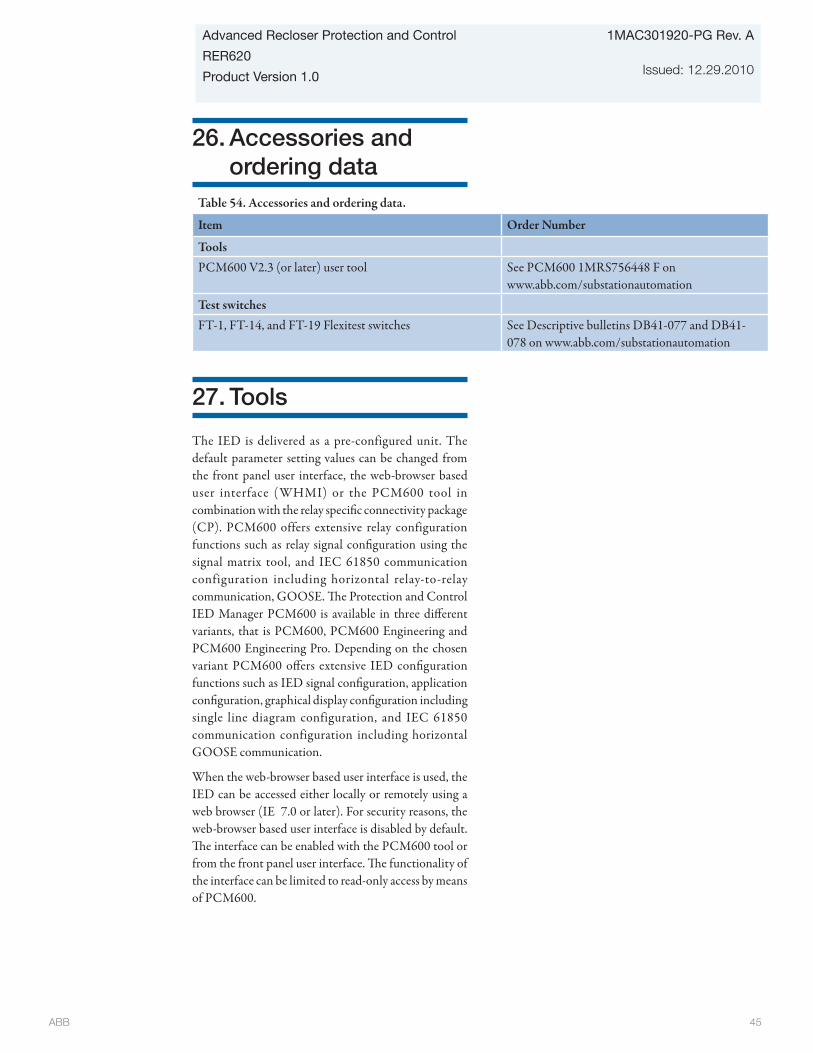
ABB 45
Advanced Recloser Protection and Control
RER620
Product Version 1.0
1MAC301920-PG Rev. A
Issued: 12.29.2010
26. Accessories and ordering data
Table 54. Accessories and ordering data.
Item Order Number
Tools PCM600 V2.3 (or later) user tool See PCM600 1MRS756448 F on
www.abb.com/substationautomationTest switchesFT-1, FT-14, and FT-19 Flexitest switches See Descriptive bulletins DB41-077 and DB41-
078 on www.abb.com/substationautomation
27. Tools
The IED is delivered as a pre-configured unit. The default parameter setting values can be changed from the front panel user interface, the web-browser based user interface (WHMI) or the PCM600 tool in combination with the relay specific connectivity package (CP). PCM600 offers extensive relay configuration functions such as relay signal configuration using the signal matrix tool, and IEC 61850 communication configuration including horizontal relay-to-relay communication, GOOSE. The Protection and Control IED Manager PCM600 is available in three different variants, that is PCM600, PCM600 Engineering and PCM600 Engineering Pro. Depending on the chosen variant PCM600 offers extensive IED configuration functions such as IED signal configuration, application configuration, graphical display configuration including single line diagram configuration, and IEC 61850 communication configuration including horizontal GOOSE communication.
When the web-browser based user interface is used, the IED can be accessed either locally or remotely using a web browser (IE 7.0 or later). For security reasons, the web-browser based user interface is disabled by default. The interface can be enabled with the PCM600 tool or from the front panel user interface. The functionality of the interface can be limited to read-only access by means of PCM600.

ABB 46
1MAC301920-PG Rev. A
Issued: 12.29.2010
Advanced Recloser Protection and Control
RER620
Product Version 1.0
Table 55. ToolsConfiguration, setting and SA system tools VersionPCM600 2.3 and PCM 2.3 Rollup 20101217
or later versions of PCM600Web-browser based user interface IE 7.0 or laterRER620 Connectivity Package 1.0 or laterCOM600 substation product V3.4 or laterMicroSCADA Pro Substation Automation system 9.2 SP1 or later
Table 56. Supported functions
Function WebHMI PCM600 PCM600 Engineering
PCM600 Engineering Pro
IED parameter setting • • • •Saving of IED parameter settings in the IED • • • •Signal monitoring • • • •Disturbance recorder handling • • • •Alarm LED viewing • • • •Access control management • • • •IED signal configuration (signal matrix) - • • •Modbus® communication configuration (communication management)
- • • •
DNP3 communication configuration (communication management)
- • • •
(communication management) - • • •Saving of IED parameter settings in the tool - • • •Disturbance record analysis - • • •XRIO parameter export/import - • • •Graphical display configuration - • • •Application configuration - • • •IEC 61850 communication configuration, GOOSE (communication configuration)
- - - •
Phasor diagram viewing • - - -
Event viewing • - - -
Saving of event data on the user’s PC • - - -
• = Supported
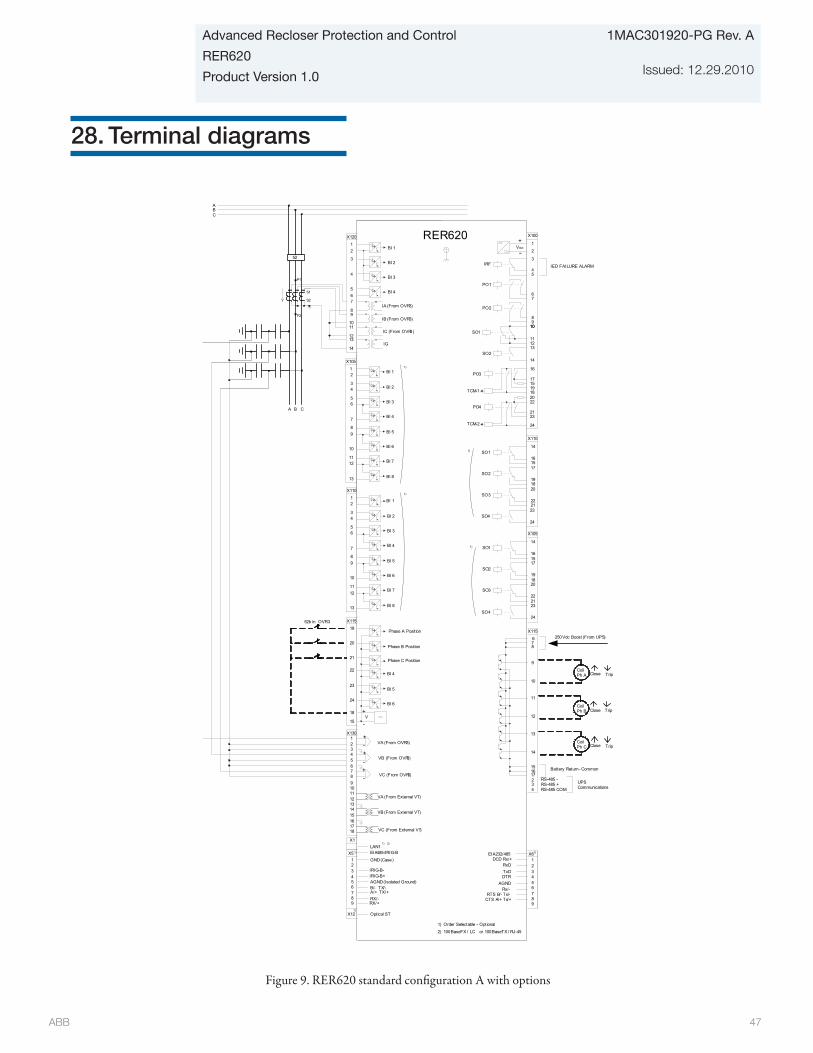
ABB 47
Advanced Recloser Protection and Control
RER620
Product Version 1.0
1MAC301920-PG Rev. A
Issued: 12.29.2010
28. Terminal diagrams
16
151918
10
111213
14
22
23
24
SO2
TCM-2
PO4
SO1
TCM-1
PO317
21
20
X120
12
3
4
567
89
1011
1213
14IG
IA (From OVR3)
BI 4
BI 3
BI 2
BI 1
RER620
ABC
S1
S2
P1
P2
52
BA C
X100
67
89
10
2
1
3
45
PO2
PO1
IRF
+
-Vaux
X110
16
14
15
19
17
18
22
20
21
SO3
SO2
SO1
IED FAILURE ALARM
24
23SO4
X110
12
56
7
89
10 BI 6
BI 5
BI 4
BI 3
BI 1
BI 8
BI 712
13
11
4 BI 23
X105
12
56
7
89
10 BI 6
BI 5
BI 4
BI 3
BI 1
BI 8
BI 712
13
11
4 BI 23
X105
16
14
15
19
17
18
22
20
21
SO3
SO2
SO1
24
23SO4
X115
9
6
10
12
11
13
2
14
34
78
151617
250Vdc Boost (From UPS)
Battery Return - Common
RS-485 -RS-485 +RS-485 COM
X115
19
20
23
24
Phase A Position
22
21
BI 6
BI 4
BI 5
+V
18
-15
X130123
9 UPS Communications
456
10
78
+-+-+-
1112131415161718
X1LAN1
VA (From External VT)
Phase B Position
Phase C Position
CoilPh A Close Trip
CoilPh B Close Trip
CoilPh C Close Trip
1)
1)
1)
1)
1) Order Selectable - Optional
2)1)
GND (Case)
RX/+RX/-A/+ TX/+B/- TX/-AGND (Isolated Ground)IRIG-B+IRIG-B-
1
9876
X5
432
5
DCD Rx/+
AGNDDTRTxDRxD
1
9876
X6
432
5Rx/-
RTS B/- Tx/-CTS A/+ Tx/+
X12 Optical ST
2) 100BaseFX / LC or 100BaseTX / RJ-45
1)
1)
1)EIA485/IRIG-B EIA232/485
VB (From External VT)
VC (From External VT)
VA (From OVR3)
VB (From OVR3)
VC (From OVR3)
IB (From OVR3)
IC (From OVR3)
52b in OVR3
Figure 9. RER620 standard configuration A with options

ABB 48
1MAC301920-PG Rev. A
Issued: 12.29.2010
Advanced Recloser Protection and Control
RER620
Product Version 1.0
29. Certificates
All type test certificates are available upon request.
ABB 49
Advanced Recloser Protection and Control
RER620
Product Version 1.0
1MAC301920-PG Rev. A
Issued: 12.29.2010
30. References
The download area on the right hand side of the web page (www.abb.com/substationautomation) contains the latest product documentation, such as techni-cal Reference manual, installation manual, operators manual, etc. The selection tool on the web page helps you find the documents by the document category and language.
The Features and Application tabs contain product re-lated information in a compact format.
The www.abb.com/substationautomation portal offers you information about the distribution automation product and service range.
You will find the latest relevant information on the RER620 protection relay on the product page.
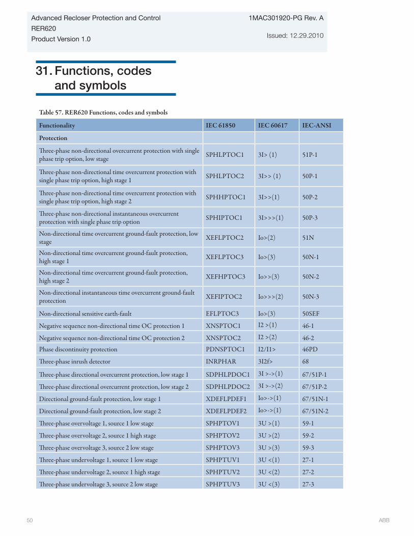
ABB 50
1MAC301920-PG Rev. A
Issued: 12.29.2010
Advanced Recloser Protection and Control
RER620
Product Version 1.0
31. Functions, codes and symbols
Table 57. RER620 Functions, codes and symbols
Functionality IEC 61850 IEC 60617 IEC-ANSI
Protection
Three-phase non-directional overcurrent protection with single phase trip option, low stage SPHLPTOC1 3I> (1) 51P-1
Three-phase non-directional time overcurrent protection with single phase trip option, high stage 1 SPHLPTOC2 3I>> (1) 50P-1
Three-phase non-directional time overcurrent protection with single phase trip option, high stage 2 SPHHPTOC1 3I>>(1) 50P-2
Three-phase non-directional instantaneous overcurrent protection with single phase trip option SPHIPTOC1 3I>>>(1) 50P-3
Non-directional time overcurrent ground-fault protection, low stage XEFLPTOC2 Io>(2) 51N
Non-directional time overcurrent ground-fault protection, high stage 1 XEFLPTOC3 Io>(3) 50N-1
Non-directional time overcurrent ground-fault protection, high stage 2 XEFHPTOC3 Io>>(3) 50N-2
Non-directional instantaneous time overcurrent ground-fault protection XEFIPTOC2 Io>>>(2) 50N-3
Non-directional sensitive earth-fault EFLPTOC3 Io>(3) 50SEF
Negative sequence non-directional time OC protection 1 XNSPTOC1 I2 >(1) 46-1
Negative sequence non-directional time OC protection 2 XNSPTOC2 I2 >(2) 46-2
Phase discontinuity protection PDNSPTOC1 I2/I1> 46PD
Three-phase inrush detector INRPHAR 3I2f> 68
Three-phase directional overcurrent protection, low stage 1 SDPHLPDOC1 3I >->(1) 67/51P-1
Three-phase directional overcurrent protection, low stage 2 SDPHLPDOC2 3I >->(2) 67/51P-2
Directional ground-fault protection, low stage 1 XDEFLPDEF1 Io>->(1) 67/51N-1
Directional ground-fault protection, low stage 2 XDEFLPDEF2 Io>->(1) 67/51N-2
Three-phase overvoltage 1, source 1 low stage SPHPTOV1 3U >(1) 59-1
Three-phase overvoltage 2, source 1 high stage SPHPTOV2 3U >(2) 59-2
Three-phase overvoltage 3, source 2 low stage SPHPTOV3 3U >(3) 59-3
Three-phase undervoltage 1, source 1 low stage SPHPTUV1 3U <(1) 27-1
Three-phase undervoltage 2, source 1 high stage SPHPTUV2 3U <(2) 27-2
Three-phase undervoltage 3, source 2 low stage SPHPTUV3 3U <(3) 27-3

ABB 51
Advanced Recloser Protection and Control
RER620
Product Version 1.0
1MAC301920-PG Rev. A
Issued: 12.29.2010
Table 57. RER620 Functions, codes and symbols (continued)
Functionality IEC 61850 IEC 60617 IEC-ANSI
Protection
Positive sequence overvoltage protection, source 1 PSPTOV1 U1>(1) 59PS-1
Positive sequence overvoltage protection, source 2 PSPTOV2 U1>(2) 59PS-2
Negative sequence overvoltage protection, source 1 NSPTOV1 U2>(1) 47-1
Negative sequence overvoltage protection, source 2 NSPTOV2 U2>(2) 47-2
Zero sequence overvoltage protection, source 1 ROVPTOV1 Uo>(1) 59N-1
Zero sequence overvoltage protection, source 2 ROVPTOV2 Uo>(2) 59N-2
Underfrequency, overfrequency, frequency rate of change, source 1 FRPFRQ1 f</f>,df/dt(1) 81-1
Underfrequency, overfrequency, frequency rate of change, source 2 FRPFRQ2 f</f>,df/dt(2) 81-2
Load Shed & Restoration, source 1 LSHDPFRQ1 UFLS/R(1) 81S-1
Load Shed & Restoration, source 2 LSHDPFRQ2 UFLS/R(2) 81S-2
Circuit breaker failure protection SCCBRBRF1 3I>/Io>BF 50BF
Circuit breaker close failure protection SCCBRBCF1 SCCBRBCF1 50BFC
Directional positive sequence power protection DPSRDIR1 P>-> 32P
Directional negative/zero sequence power protection DNZSRDIR1 Q>-> 32N
High Impedance Fault Detector PHIZ1 PHIZ1 HIZ
Cold load inrush detection, timer 1 Phase A (in seconds) TPSGAPC1 TPS(1) 62CLD-1
Cold load inrush detection timer 2 Phase A (in minutes) TPMGAPC1 TPM(1) 62CLD-2
Cold load inrush detection timer 1 Phase B (in seconds) TPSGAPC2 TPS(2) 62CLD-3
Cold load inrush detection timer 2 Phase B (in minutes) TPMGAPC2 TPM(2) 62CLD-4
Cold load inrush detection timer 1 Phase C (in seconds) TPSGAPC3 TPS(3) 62CLD-5
Cold load inrush detection timer 2 Phase C (in minutes) TPMGAPC3 TPM(3) 62CLD-6
Control
Circuit Breaker 1 (3 state inputs / 3 control outputs) SCBXCBR1 I<->O CB 52
Auto-reclosing, single phase and/or three phase SDARREC1 O -> I 79
Synchronism and energizing check SECRSYN1 SYNC 25
Loop control DLCM1 LCM LCM
Condition Monitoring
Circuit-breaker condition monitoring SPSCBR1 CBCM 52CM
Fuse failure supervision SEQRFUF1 FUSEF 60
Measurement
Digital fault (waveform) recorder RDRE1 DR DFR
Three-phase current measurement CMMXU1 3I IA,IB,IC
Sequence current measurement CSMSQI1 I1,I2,I0 I1, I2, I0
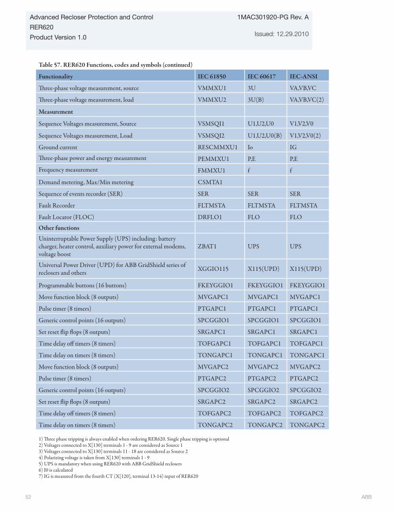
ABB 52
1MAC301920-PG Rev. A
Issued: 12.29.2010
Advanced Recloser Protection and Control
RER620
Product Version 1.0
Table 57. RER620 Functions, codes and symbols (continued)
Functionality IEC 61850 IEC 60617 IEC-ANSI
Three-phase voltage measurement, source VMMXU1 3U VA,VB,VC
Three-phase voltage measurement, load VMMXU2 3U(B) VA,VB,VC(2)
Measurement
Sequence Voltages measurement, Source VSMSQI1 U1,U2,U0 V1,V2,V0
Sequence Voltages measurement, Load VSMSQI2 U1,U2,U0(B) V1,V2,V0(2)
Ground current RESCMMXU1 Io IG
Three-phase power and energy measurement PEMMXU1 P,E P,E
Frequency measurement FMMXU1 f f
Demand metering, Max/Min metering CSMTA1
Sequence of events recorder (SER) SER SER SER
Fault Recorder FLTMSTA FLTMSTA FLTMSTA
Fault Locator (FLOC) DRFLO1 FLO FLO
Other functions
Uninterruptable Power Supply (UPS) including: battery charger, heater control, auxiliary power for external modems, voltage boost
ZBAT1 UPS UPS
Universal Power Driver (UPD) for ABB GridShield series of reclosers and others XGGIO115 X115(UPD) X115(UPD)
Programmable buttons (16 buttons) FKEYGGIO1 FKEYGGIO1 FKEYGGIO1
Move function block (8 outputs) MVGAPC1 MVGAPC1 MVGAPC1
Pulse timer (8 timers) PTGAPC1 PTGAPC1 PTGAPC1
Generic control points (16 outputs) SPCGGIO1 SPCGGIO1 SPCGGIO1
Set reset flip flops (8 outputs) SRGAPC1 SRGAPC1 SRGAPC1
Time delay off timers (8 timers) TOFGAPC1 TOFGAPC1 TOFGAPC1
Time delay on timers (8 timers) TONGAPC1 TONGAPC1 TONGAPC1
Move function block (8 outputs) MVGAPC2 MVGAPC2 MVGAPC2
Pulse timer (8 timers) PTGAPC2 PTGAPC2 PTGAPC2
Generic control points (16 outputs) SPCGGIO2 SPCGGIO2 SPCGGIO2
Set reset flip flops (8 outputs) SRGAPC2 SRGAPC2 SRGAPC2
Time delay off timers (8 timers) TOFGAPC2 TOFGAPC2 TOFGAPC2
Time delay on timers (8 timers) TONGAPC2 TONGAPC2 TONGAPC2
1) Three phase tripping is always enabled when ordering RER620. Single phase tripping is optional2) Voltages connected to X[130] terminals 1 - 9 are considered as Source 13) Voltages connected to X[130] terminals 11 - 18 are considered as Source 24) Polarizing voltage is taken from X[130] terminals 1 - 95) UPS is mandatory when using RER620 with ABB GridShield reclosers6) I0 is calculated7) IG is measured from the fourth CT (X[120], terminal 13-14) input of RER620

ABB 53
Advanced Recloser Protection and Control
RER620
Product Version 1.0
1MAC301920-PG Rev. A
Issued: 12.29.2010
32. Document revision history
Table 58. Document revision history
A / December 2010 V1.0 Initial product version release

ABB 54
1MAC301920-PG Rev. A
Issued: 12.29.2010
Advanced Recloser Protection and Control
RER620
Product Version 1.0
33. Notes

ABB 55
Advanced Recloser Protection and Control
RER620
Product Version 1.0
1MAC301920-PG Rev. A
Issued: 12.29.2010

ABB Inc. Distribution Automation4300 Coral Ridge DriveCoral Springs, Florida 33065Phone: +1 954 752 6700Fax: +1 954 345 5329
www.abb.com/substationautomation
All sales are subject to ABB Inc.General Terms and Conditions of Sale.
While every effort has been made to assure accuracy, the information in this document is subject to change without notice.
© Copyright 2010 ABB Inc. All rights reserved.
Contact us
1MA
C30
1920
-PG R
ev.
A D
ecem
ber
201
0