series 808y installation instructions
TRANSCRIPT
8/8/2019 Series 808Y Installation Instructions
http://slidepdf.com/reader/full/series-808y-installation-instructions 1/4
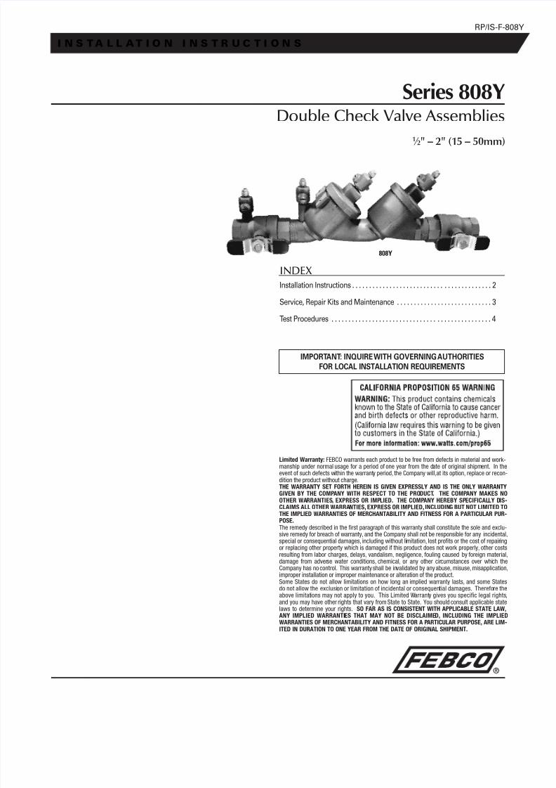
Series 808YDouble Check Valve Assemblies
1 ⁄ 2" – 2" (15 – 50mm)
RP/IS-F-808Y
I N S T A L L A T I O N I N S T R U C T I O N S
INDEXInstallation Instructions . . . . . . . . . . . . . . . . . . . . . . . . . . . . . . . . . . . . . . . . . 2
Service, Repair Kits and Maintenance . . . . . . . . . . . . . . . . . . . . . . . . . . . . 3
Test Procedures . . . . . . . . . . . . . . . . . . . . . . . . . . . . . . . . . . . . . . . . . . . . . . . 4
808Y
IMPORTANT: INQUIRE WITH GOVERNING AUTHORITIESFOR LOCAL INSTALLATION REQUIREMENTS
Limited Warranty: FEBCO warrants each product to be free from defects in material and work-manship under normal usage for a period of one year from the date of original shipment. In theevent of such defects within the warranty period, the Company will,at its option, replace or recon-dition the product without charge.THE WARRANTY SET FORTH HEREIN IS GIVEN EXPRESSLY AND IS THE ONLY WARRANGIVEN BY THE COMPANY WITH RESPECT TO THE PRODUCT. THE COMPANY MAKESOTHER WARRANTIES, EXPRESS OR IMPLIED. THE COMPANY HEREBY SPECIFICALLY DCLAIMS ALL OTHER WARRANTIES, EXPRESS OR IMPLIED, INCLUDING BUT NOT LIMITETHE IMPLIED WARRANTIES OF MERCHANTABILITY AND FITNESS FOR A PARTICULAR PPOSE.The remedy described in the first paragraph of this warranty shall constitute the sole and exclu-sive remedy for breach of warranty, and the Company shall not be responsible for any incidental,special or consequential damages, including without limitation, lost profits or the cost of repairingor replacing other property which is damaged if this product does not work properly, other costsresulting from labor charges, delays, vandalism, negligence, fouling caused by foreign material,damage from adverse water conditions, chemical, or any other circumstances over which theCompany has no control. This warranty shall be invalidated by any abuse, misuse, misapplication,improper installation or improper maintenance or alteration of the product.Some States do not allow limitations on how long an implied warranty lasts, and some Statesdo not allow the exclusion or limitation of incidental or consequential damages. Therefore theabove limitations may not apply to you. This Limited Warranty gives you specific legal rights,and you may have other rights that vary from State to State. You should consult applicable statelaws to determine your rights. SO FAR AS IS CONSISTENT WITH APPLICABLE STATE LAW,ANY IMPLIED WARRANTIES THAT MAY NOT BE DISCLAIMED, INCLUDING THE IMPLWARRANTIES OF MERCHANTABILITY AND FITNESS FOR A PARTICULAR PURPOSE, ARE LITED IN DURATION TO ONE YEAR FROM THE DATE OF ORIGINAL SHIPMENT.

8/8/2019 Series 808Y Installation Instructions
http://slidepdf.com/reader/full/series-808y-installation-instructions 2/4
Indoors - Figure 1Check local codes for installation requirements. Pipe lines should be thor-oughly flushed to remove foreign material before installing the unit. Astrainer should be installed as shown, ahead of backflow preventer to pre-vent disc from unnecessary fouling. Install valve in the line with arrow onvalve body pointing in the direction of flow.
For indoor installations, it is important that the valve be easily accessible tofacilitate testing and servicing. Do not install in a concealed location.
CAUTION: Do not install with strainer when backflow preventer is usedon seldom-used water lines which are called upon during emergencies,such as fire sprinkler lines, etc.
It is important that Series 808Y be tested periodically in compliance withlocal codes, but at least once a year or more often depending upon sys-tem conditions. Regular inspection, testing and cleaning assures maxi-mum life and proper product function.
NOTE: Fire Protection System Installations
The National Fire Protection Agency (NFPA) Guidelines require a confirm-ing flow test to be conducted whenever a “main line” valve such as theshutoff valves or a backflow assembly have been operated. Certifiedtesters of backflow assemblies must conduct this test. The trim valves ofthe confirming flow test must be closed during the test. When the test iscompleted, the trim valves must be returned to a fully open position.
Outside - Figure 2
Parallel - Figure 3Two or more Series 808Y smaller size valves may be piped in parallel(where approved) to serve a larger supply pipe main. This type of installa-tion is employed whenever it is vital to maintain a continuous supply of
water where interruptions for testing and servicing would be unaccept-able. It also has the advantage of providing increased capacity whereneeded beyond that provided by a single valve without shutting down thecomplete line. For two valve installations the total capacity should equal orexceed that required by the system.
The quantity of valves used in parallel should be determined by the engi-neer’s judgment based on operating conditions of a specific installation.
2
Installation Instructions
FirstShutoff Valve
808Y-S
Strainer
First ShutoffValve
808Y-S Vertical flow-up or vertical flow-down installation (flow-up shown)
808Y-S
Strainer
Meter Box Installation
FirstShutoff Valve
Figure 1
Figure 3
8/8/2019 Series 808Y Installation Instructions
http://slidepdf.com/reader/full/series-808y-installation-instructions 3/4
Servicing First and Second Check Valves
Servicing the First and Second Check ValvesNOTE:Before servicing, be certain water is turned off or shutoff valvesare closed.
1. Close shutoff valves up and downstream of the valve.
2. Using an appropriate sized wrench, loosen the check valve cover.Unscrew the check valve cover and lift off.
3. Remove spring.
4. Lift out disc holder assembly from body of valve.
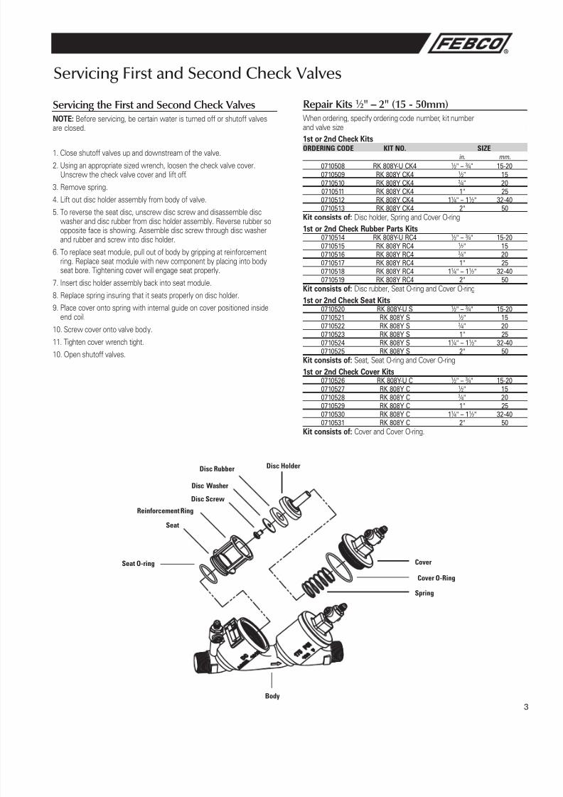
5. To reverse the seat disc, unscrew disc screw and disassemble discwasher and disc rubber from disc holder assembly. Reverse rubber soopposite face is showing. Assemble disc screw through disc washerand rubber and screw into disc holder.
6. To replace seat module, pull out of body by gripping at reinforcementring. Replace seat module with new component by placing into bodyseat bore. Tightening cover will engage seat properly.
7. Insert disc holder assembly back into seat module.
8. Replace spring insuring that it seats properly on disc holder.
9. Place cover onto spring with internal guide on cover positioned insideend coil.
10. Screw cover onto valve body.
11. Tighten cover wrench tight.
10. Open shutoff valves.
Seat O-ring
Disc Screw
Reinforcement Ring
Seat
Disc Washer
Disc Rubber Disc Holder
Cover
Cover O-Ring
Spring
Body
Repair Kits 1 ⁄ 2" – 2" (15 - 50mm)When ordering, specify ordering code number, kit numberand valve size
1st or 2nd Check KitsORDERING CODE KIT NO. SIZE
in. mm.
0710508 RK 808Y-U CK4 1 ⁄ 2" – 3 ⁄ 4" 15-200710509 RK 808Y CK4 1 ⁄ 2" 150710510 RK 808Y CK4 3 ⁄ 4" 200710511 RK 808Y CK4 1" 250710512 RK 808Y CK4 11 ⁄ 4" – 11 ⁄ 2" 32-400710513 RK 808Y CK4 2" 50
Kit consists of: Disc holder, Spring and Cover O-ring1st or 2nd Check Rubber Parts Kits
0710514 RK 808Y-U RC4 1 ⁄ 2" – 3 ⁄ 4" 15-200710515 RK 808Y RC4 1 ⁄ 2" 150710516 RK 808Y RC4 3 ⁄ 4" 200710517 RK 808Y RC4 1" 250710518 RK 808Y RC4 11 ⁄ 4" – 11 ⁄ 2" 32-400710519 RK 808Y RC4 2" 50
Kit consists of: Disc rubber, Seat O-ring and Cover O-ring1st or 2nd Check Seat Kits
0710520 RK 808Y-U S 1 ⁄ 2" – 3 ⁄ 4" 15-200710521 RK 808Y S 1 ⁄ 2" 150710522 RK 808Y S 3 ⁄ 4" 200710523 RK 808Y S 1" 250710524 RK 808Y S 11 ⁄ 4" – 11 ⁄ 2" 32-400710525 RK 808Y S 2" 50
Kit consists of: Seat, Seat O-ring and Cover O-ring1st or 2nd Check Cover Kits
0710526 RK 808Y-U C 1 ⁄ 2" – 3 ⁄ 4" 15-200710527 RK 808Y C 1 ⁄ 2" 150710528 RK 808Y C 3 ⁄ 4" 200710529 RK 808Y C 1" 250710530 RK 808Y C 11 ⁄ 4" – 11 ⁄ 2" 32-400710531 RK 808Y C 2" 50
Kit consists of: Cover and Cover O-ring.
3
8/8/2019 Series 808Y Installation Instructions
http://slidepdf.com/reader/full/series-808y-installation-instructions 4/4
Test Procedure for Double Check Valve Assemblies
A. Before starting test, all needle valves and bleed valves on test kit must be closed.
B. Flush test cocks before test.
NOTE:Supply pressure gauge reading will decrease when performing this test procedure.
Test Check Valve No. 1NOTE:Close all needle valve "A", "B" and "C" and bleed valve "A" and "B" ontest kit.
Step 1 Ensure shutoff No. 1 is open, shutoff No. 2 is closed.
Step 2 Install high side hose between connection "A" high side and test
cock No. 3, low side hose between "B" low side and test cock No.2, and open both test cock No. 2 and 3.
Step 3 Open bleed valve "A" to bleed air from the high side. Close "A" thenopen bleed valve "B" to bleed low side. Close "B".
Step 4 Connect bypass hose loosely to test cock No. 1. Open needlevalves "A" high side and "C" bypass to vent air from the bypass hose.Tighten bypass hose at test cock No. 1, open test cock No. 1
Step 5 Close shutoff No. 1. Slowly open bleed "B" until differential gaugerises to 2psi and close. If the differential reading does not decrease,record check valve as "tight".
Step 6 Close all test cocks and open bleed valves "A" and "B". Then closeneedle valves "A", "B" and "C" and bleed valves "A" and "B". Removehoses from test cocks.
Test Check Valve No. 2Step 7 Move the high side hose to test cock No. 4, low side hose to test
cock No. 3 and open both test cock No. 3 and 4. Remove bypasshose from test cock No. 1, open shutoff valve No. 1.
Step 8 Open bleed valve "A" to bleed air from the high side. Close bleed "A"then open bleed "B" to bleed low side. Close bleed "B".
Step 9 Connect bypass hose loosely to test cock No. 1. Open needlevalves "A" high side and "C" bypass to vent air from the bypasshose. Tighten bypass hose at test cock No. 1, open test cock No. 1.
Step 10 Close shutoff No. 1, then slowly open bleed "B" until differentialgauge rises to 2psi and close. If the differential reading does notdecrease, record check as tight. Close all test cocks and removehoses. Open bleed valves "A" and "B". Restore valve to originalworking condition.
NOTE:The assembly will fail both the first and second check valve testsabove, if shutoff No. 2 leaks excessively. To test for a leaky No. 2 shutoff,use the following procedure.
Test for Leaky No. 2 Shutoff
Step 11 Connect the high side hose to test cock No. 1, low side hose totest cock No. 4. Open test cocks No. 1 and 4. Close shutoffs No. 1and 2.
Step 12 Close needle valve "C" bypass. Open needle valve "A" high side,then open needle valve "B" low side one turn, loosen hose at testcock No. 4 to remove air. Retighten hose.
Step 13 If the differential gauge rises above 0, there is excessive leakage atshutoff No. 2, and it must be replaced to test the assembly.
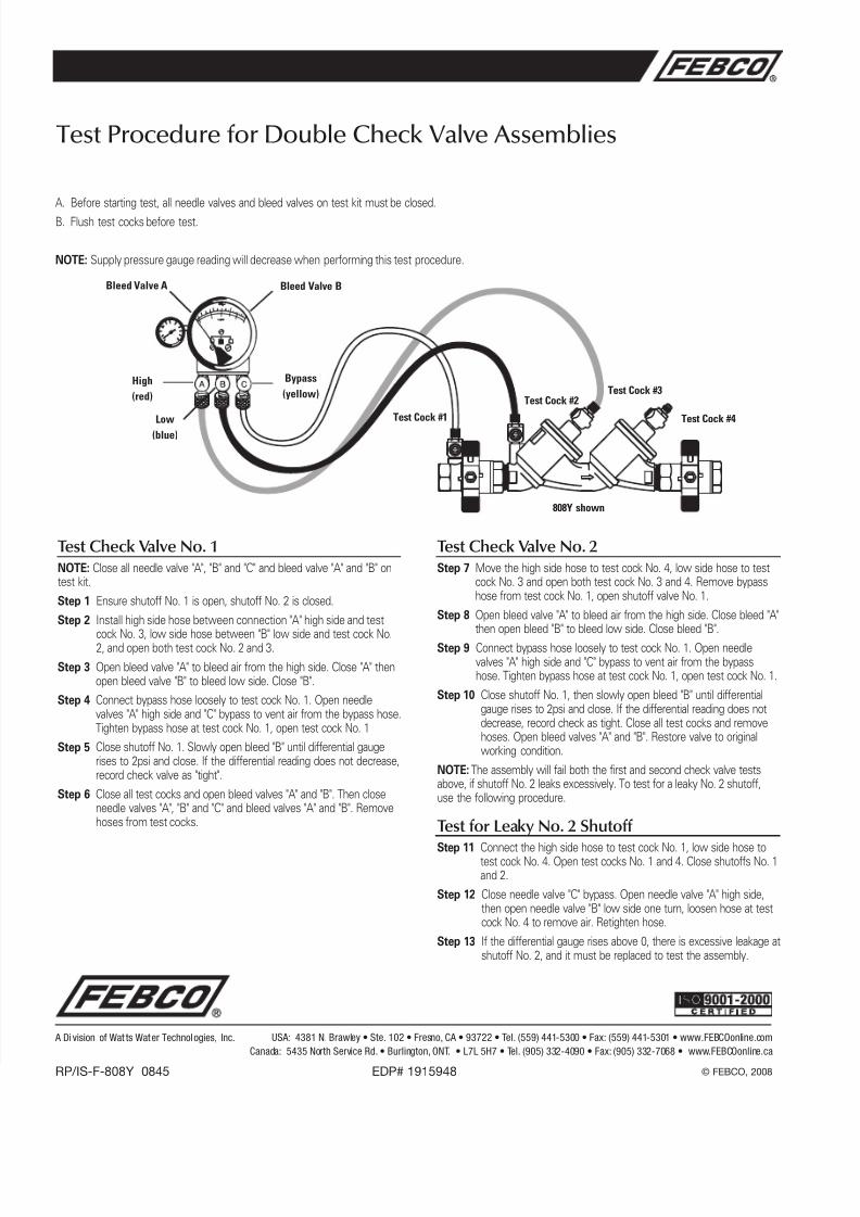
808Y shown
Bleed Valve A
High(red)
Bleed Valve B
Low(blue)
Bypass(yellow)
Test Cock #1Test Cock #2
Test Cock #3
Test Cock #4
A Di vision of Wat ts Water Technologies, Inc. USA: 4381 N. Brawley • Ste. 102 • Fresno, CA • 93722 • Tel. (559) 441-5300 • Fax: (559) 441-5301 • www.FEBCOonline.comCanada: 5435 North Service Rd. • Burlington, ONT. • L7L 5H7 • Tel. (905) 332-4090 • Fax: (905) 332-7068 • www.FEBCOonline.ca
RP/IS-F-808Y 0845 EDP# 1915948 © FEBCO, 2008