series 23h ac servo control
TRANSCRIPT

SERIES 23H
AC Servo Control
Installation & Operating Manual
1/99 MN723
AC SERVO DRIVE
Table of Contents
Table of Contents iMN723
Section 1Quick Start Guide 1-1. . . . . . . . . . . . . . . . . . . . . . . . . . . . . . . . . . . . . . . . . . . . . . . . . . . . . . . . . . . . . . . . . . . . . . . . . . . . . . . . .
Overview 1-1. . . . . . . . . . . . . . . . . . . . . . . . . . . . . . . . . . . . . . . . . . . . . . . . . . . . . . . . . . . . . . . . . . . . . . . . . . . . . . . . . . . . .
Quick Start Checklist 1-1. . . . . . . . . . . . . . . . . . . . . . . . . . . . . . . . . . . . . . . . . . . . . . . . . . . . . . . . . . . . . . . . . . . . . . .
Quick Start Procedure 1-2. . . . . . . . . . . . . . . . . . . . . . . . . . . . . . . . . . . . . . . . . . . . . . . . . . . . . . . . . . . . . . . . . . . . . .
Section 2General Information 2-1. . . . . . . . . . . . . . . . . . . . . . . . . . . . . . . . . . . . . . . . . . . . . . . . . . . . . . . . . . . . . . . . . . . . . . . . . . . . . . .
Overview 2-1. . . . . . . . . . . . . . . . . . . . . . . . . . . . . . . . . . . . . . . . . . . . . . . . . . . . . . . . . . . . . . . . . . . . . . . . . . . . . . . . . . . . .
Limited Warranty 2-2. . . . . . . . . . . . . . . . . . . . . . . . . . . . . . . . . . . . . . . . . . . . . . . . . . . . . . . . . . . . . . . . . . . . . . . . . . . . . . .
Safety Notice 2-3. . . . . . . . . . . . . . . . . . . . . . . . . . . . . . . . . . . . . . . . . . . . . . . . . . . . . . . . . . . . . . . . . . . . . . . . . . . . . . . . . .
Section 3Receiving & Installation 3-1. . . . . . . . . . . . . . . . . . . . . . . . . . . . . . . . . . . . . . . . . . . . . . . . . . . . . . . . . . . . . . . . . . . . . . . . . . .
Receiving & Inspection 3-1. . . . . . . . . . . . . . . . . . . . . . . . . . . . . . . . . . . . . . . . . . . . . . . . . . . . . . . . . . . . . . . . . . . . . . . . .
Physical Location 3-1. . . . . . . . . . . . . . . . . . . . . . . . . . . . . . . . . . . . . . . . . . . . . . . . . . . . . . . . . . . . . . . . . . . . . . . . . . . . . .
Control Installation 3-2. . . . . . . . . . . . . . . . . . . . . . . . . . . . . . . . . . . . . . . . . . . . . . . . . . . . . . . . . . . . . . . . . . . . . . . . . . . . .
Through the Wall Mounting 3-2. . . . . . . . . . . . . . . . . . . . . . . . . . . . . . . . . . . . . . . . . . . . . . . . . . . . . . . . . . . . . . . . . . . . . .
Keypad Installation Procedure 3-2. . . . . . . . . . . . . . . . . . . . . . . . . . . . . . . . . . . . . . . . . . . . . . . . . . . . . . . . . . . . . . . . . . .
Optional Remote Keypad Installation 3-3. . . . . . . . . . . . . . . . . . . . . . . . . . . . . . . . . . . . . . . . . . . . . . . . . . . . . . . . . . . . .
Electrical Installation 3-4. . . . . . . . . . . . . . . . . . . . . . . . . . . . . . . . . . . . . . . . . . . . . . . . . . . . . . . . . . . . . . . . . . . . . . . . . . .
System Grounding 3-4. . . . . . . . . . . . . . . . . . . . . . . . . . . . . . . . . . . . . . . . . . . . . . . . . . . . . . . . . . . . . . . . . . . . . . . . .
Line Impedance 3-6. . . . . . . . . . . . . . . . . . . . . . . . . . . . . . . . . . . . . . . . . . . . . . . . . . . . . . . . . . . . . . . . . . . . . . . . . . .
Line Reactors 3-7. . . . . . . . . . . . . . . . . . . . . . . . . . . . . . . . . . . . . . . . . . . . . . . . . . . . . . . . . . . . . . . . . . . . . . . . . . . . .
Load Reactors 3-7. . . . . . . . . . . . . . . . . . . . . . . . . . . . . . . . . . . . . . . . . . . . . . . . . . . . . . . . . . . . . . . . . . . . . . . . . . . .
AC Main Circuit Considerations 3-8. . . . . . . . . . . . . . . . . . . . . . . . . . . . . . . . . . . . . . . . . . . . . . . . . . . . . . . . . . . . . . . . . .
Protection Devices 3-8. . . . . . . . . . . . . . . . . . . . . . . . . . . . . . . . . . . . . . . . . . . . . . . . . . . . . . . . . . . . . . . . . . . . . . . . .
Power Disconnect 3-8. . . . . . . . . . . . . . . . . . . . . . . . . . . . . . . . . . . . . . . . . . . . . . . . . . . . . . . . . . . . . . . . . . . . . . . . .
Wire Size and Protection Devices 3-8. . . . . . . . . . . . . . . . . . . . . . . . . . . . . . . . . . . . . . . . . . . . . . . . . . . . . . . . . . . . . . . .
AC Line Connections 3-10. . . . . . . . . . . . . . . . . . . . . . . . . . . . . . . . . . . . . . . . . . . . . . . . . . . . . . . . . . . . . . . . . . . . . . . . . . .
Reduced Input Voltage Derating 3-10. . . . . . . . . . . . . . . . . . . . . . . . . . . . . . . . . . . . . . . . . . . . . . . . . . . . . . . . . . . . .
380-400 VAC Operation 3-10. . . . . . . . . . . . . . . . . . . . . . . . . . . . . . . . . . . . . . . . . . . . . . . . . . . . . . . . . . . . . . . . . . . .
Three Phase Motor and Control Connections 3-11. . . . . . . . . . . . . . . . . . . . . . . . . . . . . . . . . . . . . . . . . . . . . . . . .
Single Phase Input Power Considerations 3-14. . . . . . . . . . . . . . . . . . . . . . . . . . . . . . . . . . . . . . . . . . . . . . . . . . . .
Single Phase Control Derating 3-14. . . . . . . . . . . . . . . . . . . . . . . . . . . . . . . . . . . . . . . . . . . . . . . . . . . . . . . . . . . . . .
Size A, B and C2 Single Phase Power Installation 3-15. . . . . . . . . . . . . . . . . . . . . . . . . . . . . . . . . . . . . . . . . . . . .
Size C and D Single Phase Power Installation 3-17. . . . . . . . . . . . . . . . . . . . . . . . . . . . . . . . . . . . . . . . . . . . . . . . .
Size E Single Phase Power Installation 3-19. . . . . . . . . . . . . . . . . . . . . . . . . . . . . . . . . . . . . . . . . . . . . . . . . . . . . .
Size F Single Phase Power Installation 3-21. . . . . . . . . . . . . . . . . . . . . . . . . . . . . . . . . . . . . . . . . . . . . . . . . . . . . . .
Optional Dynamic Brake Hardware 3-23. . . . . . . . . . . . . . . . . . . . . . . . . . . . . . . . . . . . . . . . . . . . . . . . . . . . . . . . . . . . . . .
Physical Installation 3-23. . . . . . . . . . . . . . . . . . . . . . . . . . . . . . . . . . . . . . . . . . . . . . . . . . . . . . . . . . . . . . . . . . . . . . . .
Electrical Installation 3-24. . . . . . . . . . . . . . . . . . . . . . . . . . . . . . . . . . . . . . . . . . . . . . . . . . . . . . . . . . . . . . . . . . . . . . .

ii Table of Contents MN723
M-Contactor 3-27. . . . . . . . . . . . . . . . . . . . . . . . . . . . . . . . . . . . . . . . . . . . . . . . . . . . . . . . . . . . . . . . . . . . . . . . . . . . . . . . . . .
Resolver Feedback 3-27. . . . . . . . . . . . . . . . . . . . . . . . . . . . . . . . . . . . . . . . . . . . . . . . . . . . . . . . . . . . . . . . . . . . . . . . . . . .
Simulated Encoder Output 3-28. . . . . . . . . . . . . . . . . . . . . . . . . . . . . . . . . . . . . . . . . . . . . . . . . . . . . . . . . . . . . . . . . . . . . .
Home (Orient) Switch Input 3-29. . . . . . . . . . . . . . . . . . . . . . . . . . . . . . . . . . . . . . . . . . . . . . . . . . . . . . . . . . . . . . . . . . . . . .
Control Circuit Connections 3-30. . . . . . . . . . . . . . . . . . . . . . . . . . . . . . . . . . . . . . . . . . . . . . . . . . . . . . . . . . . . . . . . . . . . .
Keypad Operating Mode 3-30. . . . . . . . . . . . . . . . . . . . . . . . . . . . . . . . . . . . . . . . . . . . . . . . . . . . . . . . . . . . . . . . . . . .
Standard Run 3 Wire Mode Connections 3-32. . . . . . . . . . . . . . . . . . . . . . . . . . . . . . . . . . . . . . . . . . . . . . . . . . . . .
15 Speed 2-Wire Mode Connections 3-34. . . . . . . . . . . . . . . . . . . . . . . . . . . . . . . . . . . . . . . . . . . . . . . . . . . . . . . . .
3 Speed Analog 2 Wire Control Mode 3-36. . . . . . . . . . . . . . . . . . . . . . . . . . . . . . . . . . . . . . . . . . . . . . . . . . . . . . . .
3 Speed Analog 3 Wire Control Mode 3-37. . . . . . . . . . . . . . . . . . . . . . . . . . . . . . . . . . . . . . . . . . . . . . . . . . . . . . . .
Bipolar Speed or Torque Mode Connections 3-38. . . . . . . . . . . . . . . . . . . . . . . . . . . . . . . . . . . . . . . . . . . . . . . . . .
EPOT 2 Wire Control Mode 3-40. . . . . . . . . . . . . . . . . . . . . . . . . . . . . . . . . . . . . . . . . . . . . . . . . . . . . . . . . . . . . . . . .
EPOT 3 Wire Control Mode 3-41. . . . . . . . . . . . . . . . . . . . . . . . . . . . . . . . . . . . . . . . . . . . . . . . . . . . . . . . . . . . . . . . .
Process Mode Connections 3-42. . . . . . . . . . . . . . . . . . . . . . . . . . . . . . . . . . . . . . . . . . . . . . . . . . . . . . . . . . . . . . . . .
Process Mode Outputs 3-44. . . . . . . . . . . . . . . . . . . . . . . . . . . . . . . . . . . . . . . . . . . . . . . . . . . . . . . . . . . . . . . . . . . . .
Analog Inputs and Outputs 3-46. . . . . . . . . . . . . . . . . . . . . . . . . . . . . . . . . . . . . . . . . . . . . . . . . . . . . . . . . . . . . . . . . . . . . .
Analog Inputs 3-46. . . . . . . . . . . . . . . . . . . . . . . . . . . . . . . . . . . . . . . . . . . . . . . . . . . . . . . . . . . . . . . . . . . . . . . . . . . . .
Analog Outputs 3-49. . . . . . . . . . . . . . . . . . . . . . . . . . . . . . . . . . . . . . . . . . . . . . . . . . . . . . . . . . . . . . . . . . . . . . . . . . . .
External Trip Input 3-50. . . . . . . . . . . . . . . . . . . . . . . . . . . . . . . . . . . . . . . . . . . . . . . . . . . . . . . . . . . . . . . . . . . . . . . . . . . . .
Opto-Isolated Inputs 3-50. . . . . . . . . . . . . . . . . . . . . . . . . . . . . . . . . . . . . . . . . . . . . . . . . . . . . . . . . . . . . . . . . . . . . . . . . . . .
Opto-Isolated Outputs 3-52. . . . . . . . . . . . . . . . . . . . . . . . . . . . . . . . . . . . . . . . . . . . . . . . . . . . . . . . . . . . . . . . . . . . . . . . . .
Pre-Operation Checklist 3-53. . . . . . . . . . . . . . . . . . . . . . . . . . . . . . . . . . . . . . . . . . . . . . . . . . . . . . . . . . . . . . . . . . . . . . . .
Power-Up Procedure 3-54. . . . . . . . . . . . . . . . . . . . . . . . . . . . . . . . . . . . . . . . . . . . . . . . . . . . . . . . . . . . . . . . . . . . . . . . . . .
Section 4Programming and Operation 4-1. . . . . . . . . . . . . . . . . . . . . . . . . . . . . . . . . . . . . . . . . . . . . . . . . . . . . . . . . . . . . . . . . . . . . . .
Overview 4-1. . . . . . . . . . . . . . . . . . . . . . . . . . . . . . . . . . . . . . . . . . . . . . . . . . . . . . . . . . . . . . . . . . . . . . . . . . . . . . . . . . . . .
Display Mode 4-2. . . . . . . . . . . . . . . . . . . . . . . . . . . . . . . . . . . . . . . . . . . . . . . . . . . . . . . . . . . . . . . . . . . . . . . . . . . . . . . . . .
Adjusting Display Contrast 4-2. . . . . . . . . . . . . . . . . . . . . . . . . . . . . . . . . . . . . . . . . . . . . . . . . . . . . . . . . . . . . . . . . .
Display Mode Screens 4-2. . . . . . . . . . . . . . . . . . . . . . . . . . . . . . . . . . . . . . . . . . . . . . . . . . . . . . . . . . . . . . . . . . . . .
Diagnostic Information Access 4-3. . . . . . . . . . . . . . . . . . . . . . . . . . . . . . . . . . . . . . . . . . . . . . . . . . . . . . . . . . . . . .
Fault Log Access 4-4. . . . . . . . . . . . . . . . . . . . . . . . . . . . . . . . . . . . . . . . . . . . . . . . . . . . . . . . . . . . . . . . . . . . . . . . . .
Program Mode 4-5. . . . . . . . . . . . . . . . . . . . . . . . . . . . . . . . . . . . . . . . . . . . . . . . . . . . . . . . . . . . . . . . . . . . . . . . . . . . . . . .
Parameter Blocks Access for Programming 4-5. . . . . . . . . . . . . . . . . . . . . . . . . . . . . . . . . . . . . . . . . . . . . . . . . . .
Changing Parameter Values when Security Code Not Used 4-6. . . . . . . . . . . . . . . . . . . . . . . . . . . . . . . . . . . .
Reset Parameters to Factory Settings 4-7. . . . . . . . . . . . . . . . . . . . . . . . . . . . . . . . . . . . . . . . . . . . . . . . . . . . . . . .
Initialize New Software 4-8. . . . . . . . . . . . . . . . . . . . . . . . . . . . . . . . . . . . . . . . . . . . . . . . . . . . . . . . . . . . . . . . . . . . .
Parameter Definitions 4-9. . . . . . . . . . . . . . . . . . . . . . . . . . . . . . . . . . . . . . . . . . . . . . . . . . . . . . . . . . . . . . . . . . . . . . . . . .

Table of Contents iiiMN723
Section 5Troubleshooting 5-1. . . . . . . . . . . . . . . . . . . . . . . . . . . . . . . . . . . . . . . . . . . . . . . . . . . . . . . . . . . . . . . . . . . . . . . . . . . . . . . . . .
Overview 5-1. . . . . . . . . . . . . . . . . . . . . . . . . . . . . . . . . . . . . . . . . . . . . . . . . . . . . . . . . . . . . . . . . . . . . . . . . . . . . . . . . . . . .
No Keypad Display - Display Contrast Adjustment 5-1. . . . . . . . . . . . . . . . . . . . . . . . . . . . . . . . . . . . . . . . . . . . . . . . . .
How to Access Diagnostic Information 5-2. . . . . . . . . . . . . . . . . . . . . . . . . . . . . . . . . . . . . . . . . . . . . . . . . . . . . . . .
How to Access the Fault Log 5-3. . . . . . . . . . . . . . . . . . . . . . . . . . . . . . . . . . . . . . . . . . . . . . . . . . . . . . . . . . . . . . . . . . . .
How to Clear the Fault Log 5-3. . . . . . . . . . . . . . . . . . . . . . . . . . . . . . . . . . . . . . . . . . . . . . . . . . . . . . . . . . . . . . . . . . . . . .
Electrical Noise Considerations 5-10. . . . . . . . . . . . . . . . . . . . . . . . . . . . . . . . . . . . . . . . . . . . . . . . . . . . . . . . . . . . . . . . . .
Causes and Cures 5-10. . . . . . . . . . . . . . . . . . . . . . . . . . . . . . . . . . . . . . . . . . . . . . . . . . . . . . . . . . . . . . . . . . . . . . . . .
Special Drive Situations 5-13. . . . . . . . . . . . . . . . . . . . . . . . . . . . . . . . . . . . . . . . . . . . . . . . . . . . . . . . . . . . . . . . . . . .
Drive Power Lines 5-13. . . . . . . . . . . . . . . . . . . . . . . . . . . . . . . . . . . . . . . . . . . . . . . . . . . . . . . . . . . . . . . . . . . . . . . . .
Radio Transmitters 5-13. . . . . . . . . . . . . . . . . . . . . . . . . . . . . . . . . . . . . . . . . . . . . . . . . . . . . . . . . . . . . . . . . . . . . . . .
Control Enclosures 5-14. . . . . . . . . . . . . . . . . . . . . . . . . . . . . . . . . . . . . . . . . . . . . . . . . . . . . . . . . . . . . . . . . . . . . . . .
Special Motor Considerations 5-14. . . . . . . . . . . . . . . . . . . . . . . . . . . . . . . . . . . . . . . . . . . . . . . . . . . . . . . . . . . . . . .
Wiring Practices 5-14. . . . . . . . . . . . . . . . . . . . . . . . . . . . . . . . . . . . . . . . . . . . . . . . . . . . . . . . . . . . . . . . . . . . . . . . . . . . . . .
Optical Isolation 5-15. . . . . . . . . . . . . . . . . . . . . . . . . . . . . . . . . . . . . . . . . . . . . . . . . . . . . . . . . . . . . . . . . . . . . . . . . . . . . . .
Plant Ground 5-15. . . . . . . . . . . . . . . . . . . . . . . . . . . . . . . . . . . . . . . . . . . . . . . . . . . . . . . . . . . . . . . . . . . . . . . . . . . . . . . . . .
Section 6Manual Tuning the Series 23H Control 6-1. . . . . . . . . . . . . . . . . . . . . . . . . . . . . . . . . . . . . . . . . . . . . . . . . . . . . . . . . . . . . .
Manually Tuning the Control 6-1. . . . . . . . . . . . . . . . . . . . . . . . . . . . . . . . . . . . . . . . . . . . . . . . . . . . . . . . . . . . . . . . . . . . .
Current Prop Gain Parameter 6-1. . . . . . . . . . . . . . . . . . . . . . . . . . . . . . . . . . . . . . . . . . . . . . . . . . . . . . . . . . . . . . .
Current INT Gain Parameter 6-1. . . . . . . . . . . . . . . . . . . . . . . . . . . . . . . . . . . . . . . . . . . . . . . . . . . . . . . . . . . . . . . .
Speed Prop Gain Parameter 6-1. . . . . . . . . . . . . . . . . . . . . . . . . . . . . . . . . . . . . . . . . . . . . . . . . . . . . . . . . . . . . . . .
Speed Int Gain Parameter 6-2. . . . . . . . . . . . . . . . . . . . . . . . . . . . . . . . . . . . . . . . . . . . . . . . . . . . . . . . . . . . . . . . . .
PI Controller 6-2. . . . . . . . . . . . . . . . . . . . . . . . . . . . . . . . . . . . . . . . . . . . . . . . . . . . . . . . . . . . . . . . . . . . . . . . . . . . . .

iv Table of Contents MN723
Section 7Specifications, Ratings & Dimensions 7-1. . . . . . . . . . . . . . . . . . . . . . . . . . . . . . . . . . . . . . . . . . . . . . . . . . . . . . . . . . . . . .
Specifications 7-1. . . . . . . . . . . . . . . . . . . . . . . . . . . . . . . . . . . . . . . . . . . . . . . . . . . . . . . . . . . . . . . . . . . . . . . . . . . . . . . . .
Operating Conditions 7-1. . . . . . . . . . . . . . . . . . . . . . . . . . . . . . . . . . . . . . . . . . . . . . . . . . . . . . . . . . . . . . . . . . . . . . .
Resolver Feedback 7-1. . . . . . . . . . . . . . . . . . . . . . . . . . . . . . . . . . . . . . . . . . . . . . . . . . . . . . . . . . . . . . . . . . . . . . . .
Keypad Display 7-2. . . . . . . . . . . . . . . . . . . . . . . . . . . . . . . . . . . . . . . . . . . . . . . . . . . . . . . . . . . . . . . . . . . . . . . . . . .
Control Specifications 7-2. . . . . . . . . . . . . . . . . . . . . . . . . . . . . . . . . . . . . . . . . . . . . . . . . . . . . . . . . . . . . . . . . . . . . .
Differential Analog Input 7-2. . . . . . . . . . . . . . . . . . . . . . . . . . . . . . . . . . . . . . . . . . . . . . . . . . . . . . . . . . . . . . . . . . . .
Analog Outputs 7-3. . . . . . . . . . . . . . . . . . . . . . . . . . . . . . . . . . . . . . . . . . . . . . . . . . . . . . . . . . . . . . . . . . . . . . . . . . . .
Digital Inputs 7-3. . . . . . . . . . . . . . . . . . . . . . . . . . . . . . . . . . . . . . . . . . . . . . . . . . . . . . . . . . . . . . . . . . . . . . . . . . . . . .
Digital Outputs 7-3. . . . . . . . . . . . . . . . . . . . . . . . . . . . . . . . . . . . . . . . . . . . . . . . . . . . . . . . . . . . . . . . . . . . . . . . . . . .
Diagnostic Indications 7-3. . . . . . . . . . . . . . . . . . . . . . . . . . . . . . . . . . . . . . . . . . . . . . . . . . . . . . . . . . . . . . . . . . . . . .
Ratings 7-4. . . . . . . . . . . . . . . . . . . . . . . . . . . . . . . . . . . . . . . . . . . . . . . . . . . . . . . . . . . . . . . . . . . . . . . . . . . . . . . . . . . . . . .
Terminal Tightening Torque Specifications 7-5. . . . . . . . . . . . . . . . . . . . . . . . . . . . . . . . . . . . . . . . . . . . . . . . . . . . . . . . .
Dimensions 7-6. . . . . . . . . . . . . . . . . . . . . . . . . . . . . . . . . . . . . . . . . . . . . . . . . . . . . . . . . . . . . . . . . . . . . . . . . . . . . . . . . . .
Size A Control 7-6. . . . . . . . . . . . . . . . . . . . . . . . . . . . . . . . . . . . . . . . . . . . . . . . . . . . . . . . . . . . . . . . . . . . . . . . . . . .
Size A Control – Through–Wall Mounting 7-7. . . . . . . . . . . . . . . . . . . . . . . . . . . . . . . . . . . . . . . . . . . . . . . . . . . . .
Size B Control 7-8. . . . . . . . . . . . . . . . . . . . . . . . . . . . . . . . . . . . . . . . . . . . . . . . . . . . . . . . . . . . . . . . . . . . . . . . . . . .
Size B Control – Through–Wall Mounting 7-9. . . . . . . . . . . . . . . . . . . . . . . . . . . . . . . . . . . . . . . . . . . . . . . . . . . . .
Size C Control 7-10. . . . . . . . . . . . . . . . . . . . . . . . . . . . . . . . . . . . . . . . . . . . . . . . . . . . . . . . . . . . . . . . . . . . . . . . . . . .
Size C2 Control 7-11. . . . . . . . . . . . . . . . . . . . . . . . . . . . . . . . . . . . . . . . . . . . . . . . . . . . . . . . . . . . . . . . . . . . . . . . . . .
Size C2 Control – Through–Wall Mounting 7-12. . . . . . . . . . . . . . . . . . . . . . . . . . . . . . . . . . . . . . . . . . . . . . . . . . . .
Size D Control 7-13. . . . . . . . . . . . . . . . . . . . . . . . . . . . . . . . . . . . . . . . . . . . . . . . . . . . . . . . . . . . . . . . . . . . . . . . . . . .
Size E Control 7-14. . . . . . . . . . . . . . . . . . . . . . . . . . . . . . . . . . . . . . . . . . . . . . . . . . . . . . . . . . . . . . . . . . . . . . . . . . . . .
Size E Control – Through–Wall Mounting 7-15. . . . . . . . . . . . . . . . . . . . . . . . . . . . . . . . . . . . . . . . . . . . . . . . . . . . .
Size F Control 7-17. . . . . . . . . . . . . . . . . . . . . . . . . . . . . . . . . . . . . . . . . . . . . . . . . . . . . . . . . . . . . . . . . . . . . . . . . . . .
Size F Control – Through–Wall Mounting 7-18. . . . . . . . . . . . . . . . . . . . . . . . . . . . . . . . . . . . . . . . . . . . . . . . . . . . .
Size G Control 7-20. . . . . . . . . . . . . . . . . . . . . . . . . . . . . . . . . . . . . . . . . . . . . . . . . . . . . . . . . . . . . . . . . . . . . . . . . . . .
Appendix A A-1. . . . . . . . . . . . . . . . . . . . . . . . . . . . . . . . . . . . . . . . . . . . . . . . . . . . . . . . . . . . . . . . . . . . . . . . . . . . . . . . . . . . . . .
Dynamic Braking (DB) Hardware A-1. . . . . . . . . . . . . . . . . . . . . . . . . . . . . . . . . . . . . . . . . . . . . . . . . . . . . . . . . . . . . . . . .
RGA Assemblies A-4. . . . . . . . . . . . . . . . . . . . . . . . . . . . . . . . . . . . . . . . . . . . . . . . . . . . . . . . . . . . . . . . . . . . . . . . . .
RBA Assemblies A-5. . . . . . . . . . . . . . . . . . . . . . . . . . . . . . . . . . . . . . . . . . . . . . . . . . . . . . . . . . . . . . . . . . . . . . . . . .
RTA Assemblies A-6. . . . . . . . . . . . . . . . . . . . . . . . . . . . . . . . . . . . . . . . . . . . . . . . . . . . . . . . . . . . . . . . . . . . . . . . . . .
Appendix B B-1. . . . . . . . . . . . . . . . . . . . . . . . . . . . . . . . . . . . . . . . . . . . . . . . . . . . . . . . . . . . . . . . . . . . . . . . . . . . . . . . . . . . . . .
Parameter Values B-1. . . . . . . . . . . . . . . . . . . . . . . . . . . . . . . . . . . . . . . . . . . . . . . . . . . . . . . . . . . . . . . . . . . . . . . . . . . . . .
Appendix C C-1. . . . . . . . . . . . . . . . . . . . . . . . . . . . . . . . . . . . . . . . . . . . . . . . . . . . . . . . . . . . . . . . . . . . . . . . . . . . . . . . . . . . . . .
Remote Keypad Mounting Template C-2. . . . . . . . . . . . . . . . . . . . . . . . . . . . . . . . . . . . . . . . . . . . . . . . . . . . . . . . . . . . . .

Section 1Quick Start Guide
Quick Start Guide 1-1MN723
Overview If you are an experienced user of Baldor controls, you are probably already familiar withthe keypad programming and keypad operation methods. If so, this quick start guide hasbeen prepared for you. This procedure will help get your system up and running in theKeypad mode quickly. This will allow motor and control operation to be verified. Thisprocedure assumes that the control, motor and dynamic brake hardware are correctlyinstalled (see Section 3 for procedures) and that you have an understanding of thekeypad programming & operation procedures. It is not necessary to wire the terminalstrip to operate in the keypad mode (Section 3 describes terminal strip wiringprocedures). The quick start procedure is as follows:
1. Read the Safety Notice and Precautions in section 2 of this manual.
2. Mount the control. Refer to Section 3 “Physical Location” procedure.
3. Connect AC power, refer to Section 3 “Three Phase Motor and ControlConnections”.
4. Connect the motor, refer to Section 3 “Three Phase Motor and ControlConnections”.
5. Connect the resolver, refer to Section 3 “Resolver Feedback”.
6. Install dynamic brake hardware, if required. Refer to Section 3 “OptionalDynamic Brake Hardware”.
7. Connect the keypad to the keypad connector of the main control board. Referto Section 3 “Keypad Installation Procedure”.
Quick Start Checklist Check of electrical items.
CAUTION: After completing the installation but before you apply power, besure to check the following items.
1. Verify AC line voltage at source matches control rating.
2. Inspect all power connections for accuracy, workmanship and torque as well ascompliance to codes.
3. Verify control and motor are grounded to each other and the control isconnected to earth ground.
4. Check all signal wiring for accuracy.
5. Be certain all brake coils, contactors and relay coils have noise suppression.This should be an R-C filter for AC coils and reverse polarity diodes for DCcoils. MOV type transient suppression is not adequate.
WARNING: Make sure that unexpected operation of the motor shaft during startup will not cause injury to personnel or damage to equipment.
Check of Motors and Couplings
1. Verify freedom of motion of the motor shaft.
2. Verify that all motor couplings are tight without backlash.
3. Verify the holding brakes if any, are properly adjusted to fully release and set tothe desired torque value.

Section 1General Information
1-2 Quick Start Guide MN723
Quick Start ProcedureInitial ConditionsBe sure the 23H control, motor and dynamic brake hardware are installed and wiredaccording to the procedures in Section 3 of this manual. Become familiar with the keypad programming and keypad operation of the control asdescribed in Section 4 of this manual.
1. Disconnect the load (including coupling or inertia wheels) from the motor shaft,if possible.
2. Verify that any enable inputs to J1-8 are open. Be sure Level 2 Protectionblock, Local Enable INP is OFF and Level 2 Protection block, External Trip isOFF.
3. Turn power on. Be sure no errors are displayed.
4. Set the Level 1 Input block, Operating Mode parameter to “KEYPAD”.
5. Set the Level 2 Output Limits block, “OPERATING ZONE” parameter as desired(STD CONST TQ, STD VAR TQ, QUIET CONST TQ or QUIET VAR TQ).
6. Enter the following motor data in the Level 2 Motor Data block parameters:Motor Rated Amps (IC)Motor PolesResolver Speeds (Pre-set is one speed)
7. If external dynamic brake hardware is used, set the Level 2 Brake Adjust block“Resistor Ohms”, “Resistor Watts” and “DC Brake Current” parameters.
8. If the load was not disconnected in step 1, refer to Section 6 and manually tunethe control. After manual tuning, perform steps 11 and 12 then continue withstep 16.
9. At the Level 2 Motor Data block, press ENTER, at CALC PRESETS select YES(using the � key) and let the control calculate preset values for the parametersthat are necessary for control operation.
WARNING: The motor shaft will rotate during the autotune procedure. Becertain that unexpected motor shaft movement will not cause injuryto personnel or damage to equipment.
10. Go to Level 2 Autotune block, and perform the following tests:CMD OFFSET TRIMCUR LOOP COMPRESOLVER ALIGN
11. Set the Level 2 Output Limits block, “MIN OUTPUT SPEED” parameter.
12. Set the Level 2 Output Limits block, “MAX OUTPUT SPEED” parameter.
13. Remove all power from the control.
14. Couple the motor to its load.
15. Turn power on. Be sure no errors are displayed.
16. Perform the SPD CNTRLR CALC test in the Level 2 Autotune block.
17. Run the drive from the keypad using the arrow keys for direct speed control, akeypad entered speed or the JOG mode.
18. Select and program additional parameters to suit your application.
The control is now ready for use the in keypad mode. If a different operating mode isdesired, refer to Section 3 Control Connections and Section 4 Programming andOperation.

Section 2General Information
General Information 2-1MN723
Overview The Baldor Series 23H PWM control uses a closed loop control scheme using analgorithm to adjust the phase of voltage and current applied to a three phase permanentmagnet synchronous motor. The servo control adjusts the motor current to producemaximum torque from base speed down to and including zero speed. The frequency ofthe voltage applied to the motor follows the electrical cycles per revolution based on themechanical speed of the rotor. This provides instantaneous adjustment of the voltageand current phasing in response to speed and position feedback from a resolver mountedto the motors’ shaft.

2-2 General Information MN723
Limited Warranty
For a period of two (2) years from the date of original purchase, BALDOR willrepair or replace without charge controls and accessories which ourexamination proves to be defective in material or workmanship. Thiswarranty is valid if the unit has not been tampered with by unauthorizedpersons, misused, abused, or improperly installed and has been used inaccordance with the instructions and/or ratings supplied. This warranty is inlieu of any other warranty or guarantee expressed or implied. BALDORshall not be held responsible for any expense (including installation andremoval), inconvenience, or consequential damage, including injury to anyperson or property caused by items of our manufacture or sale. (Somestates do not allow exclusion or limitation of incidental or consequentialdamages, so the above exclusion may not apply.) In any event, BALDOR’stotal liability, under all circumstances, shall not exceed the full purchaseprice of the control. Claims for purchase price refunds, repairs, orreplacements must be referred to BALDOR with all pertinent data as to thedefect, the date purchased, the task performed by the control, and theproblem encountered. No liability is assumed for expendable items such asfuses.
Goods may be returned only with written notification including a BALDORReturn Authorization Number and any return shipments must be prepaid.

General Information 2-3MN723
Safety Notice This equipment contains voltages that may be as high as 1000 volts! Electrical shockcan cause serious or fatal injury. Only qualified personnel should attempt the start–upprocedure or troubleshoot this equipment.
This equipment may be connected to other machines that have rotating parts or partsthat are driven by this equipment. Improper use can cause serious or fatal injury. Onlyqualified personnel should attempt the start–up procedure or troubleshoot this equipment.
PRECAUTIONS
WARNING: Do not touch any circuit board, power device or electricalconnection before you first ensure that power has beendisconnected and there is no high voltage present from thisequipment or other equipment to which it is connected. Electricalshock can cause serious or fatal injury. Only qualified personnelshould attempt the start–up procedure or troubleshoot thisequipment.
WARNING: This unit has an automatic restart feature that will start the motorwhenever input power is applied and a RUN (FWD or REV)command is issued. If an automatic restart of the motor couldcause injury to personnel, the automatic restart feature should bedisabled by changing the Level 2 Miscellaneous block, RestartAuto/Man parameter to Manual.
WARNING: Do not remove cover for at least five (5) minutes after AC power isdisconnected to allow capacitors to discharge. Dangerous voltagesare present inside the equipment. Electrical shock can causeserious or fatal injury.
WARNING: Be sure that you are completely familiar with the safe operation ofthis equipment. This equipment may be connected to othermachines that have rotating parts or parts that are controlled bythis equipment. Improper use can cause serious or fatal injury.Only qualified personnel should attempt the start–up procedure ortroubleshoot this equipment.
WARNING: Be sure the system is properly grounded before applying power.Do not apply AC power before you ensure that all groundinginstructions have been followed. Electrical shock can causeserious or fatal injury.
WARNING: Improper operation of control may cause violent motion of themotor shaft and driven equipment. Be certain that unexpectedmotor shaft movement will not cause injury to personnel or damageto equipment. Certain failure modes of the control can producepeak torque of several times the rated motor torque.
WARNING: Motor circuit may have high voltage present whenever AC power isapplied, even when motor is not rotating. Electrical shock cancause serious or fatal injury.
WARNING: Dynamic brake resistors may generate enough heat to ignitecombustible materials. Keep all combustible materials andflammable vapors away from brake resistors.
WARNING: The motor shaft will rotate during the autotune procedure. Becertain that unexpected motor shaft movement will not cause injuryto personnel or damage to equipment.
Continued on next page

Section 1General Information
2-4 General Information MN723
Caution: Disconnect motor leads (T1, T2 and T3) from control before youperform a “Megger” test on the motor. Failure to disconnect motorfrom the control will result in extensive damage to the control. Thecontrol is tested at the factory for high voltage / leakage resistanceas part of Underwriter Laboratory requirements.
Caution: Do not supply any power to the External Trip (motor thermostat)leads at J1-16 and 17. Power on these leads can damage thecontrol. Use a dry contact type that requires no external power tooperate.
Caution: Do not connect AC power to the Motor terminals T1, T2 and T3.Connecting AC power to these terminals may result in damage tothe control.
Caution: Baldor recommends not using “Grounded Leg Delta” transformerpower leads that may create ground loops. Instead, we recommendusing a four wire Wye.
Caution: If the DB hardware mounting is in any position other than vertical,the DB hardware must be derated by 35% of its rated capacity.
Caution: If an M-Contactor is installed, the control must be disabled for atleast 20msec before the M-Contactor is opened. If the M-Contactoris opened while the control is supplying voltage and current to themotor, the control may be damaged.
Caution: Do not connect any shields to the motor frame. At a minimum,resolver signal integrity will be compromised and damage to thecontrol may result. The resolver shields must be connected atJ1-28 only.
Section 3Receiving & Installation
Receiving & Installation 3-1MN723
Receiving & Inspection The Series 23H Control is thoroughly tested at the factory and carefully packaged forshipment. When you receive your control, there are several things you should doimmediately.
1. Observe the condition of the shipping container and report any damageimmediately to the commercial carrier that delivered your control.
2. Verify that the part number of the control you received is the same as the partnumber listed on your purchase order.
3. If the control is to be stored for several weeks before use, be sure that it isstored in a location that conforms to published storage temperature andhumidity specifications. (Refer to Section 7 of this manual).
Physical Location The location of the 23H is important. It should be installed in an area that is protectedfrom direct sunlight, corrosives, harmful gases or liquids, dust, metallic particles, shockand vibration. Exposure to these elements and/or conditions can reduce the operatinglife and degrade performance of the control.
Several other factors should be carefully evaluated when selecting a location forinstallation:
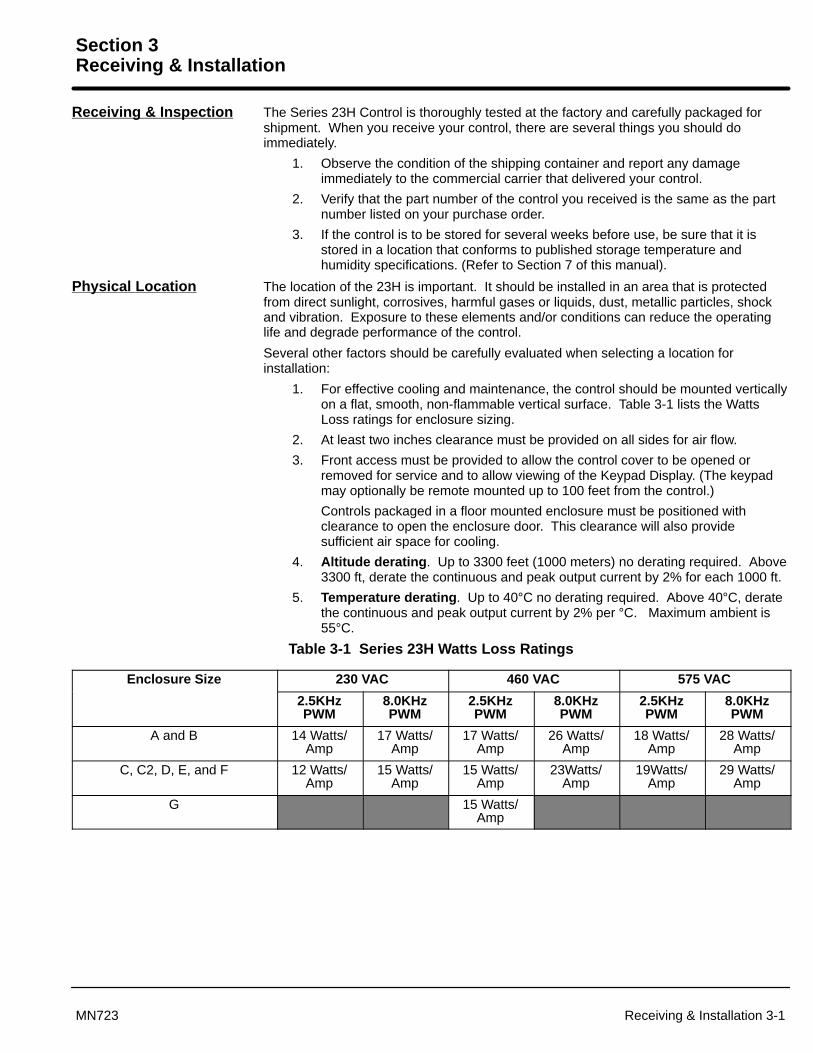
1. For effective cooling and maintenance, the control should be mounted verticallyon a flat, smooth, non-flammable vertical surface. Table 3-1 lists the WattsLoss ratings for enclosure sizing.
2. At least two inches clearance must be provided on all sides for air flow.
3. Front access must be provided to allow the control cover to be opened orremoved for service and to allow viewing of the Keypad Display. (The keypadmay optionally be remote mounted up to 100 feet from the control.)
Controls packaged in a floor mounted enclosure must be positioned withclearance to open the enclosure door. This clearance will also providesufficient air space for cooling.
4. Altitude derating . Up to 3300 feet (1000 meters) no derating required. Above3300 ft, derate the continuous and peak output current by 2% for each 1000 ft.
5. Temperature derating . Up to 40°C no derating required. Above 40°C, deratethe continuous and peak output current by 2% per °C. Maximum ambient is55°C.
Table 3-1 Series 23H Watts Loss Ratings
Enclosure Size 230 VAC 460 VAC 575 VAC
2.5KHzPWM
8.0KHzPWM
2.5KHzPWM
8.0KHzPWM
2.5KHzPWM
8.0KHzPWM
A and B 14 Watts/Amp
17 Watts/Amp
17 Watts/Amp
26 Watts/Amp
18 Watts/Amp
28 Watts/Amp
C, C2, D, E, and F 12 Watts/Amp
15 Watts/Amp
15 Watts/Amp
23Watts/Amp
19Watts/Amp
29 Watts/Amp
G 15 Watts/Amp

Section 1General Information
3-2 Receiving & Installation MN723
Control Installation The control must be securely fastened to the mounting surface. Use the four (4)mounting holes to fasten the control to the mounting surface or enclosure.
Shock Mounting
If the control will be subjected to levels of shock greater than 1G or vibration greater than0.5G at 10 to 60Hz, the control should be shock mounted. Excessive vibration within thecontrol could cause internal connections to loosen and cause component failure orelectrical shock hazard.
Through the Wall Mounting Control sizes A, B, C2, E and F are designed for panel or through the wall installation. Tomount a control through the wall, a Through the Wall mounting kit must be purchased(except for C2 size). These kits are:
Kit No. DescriptionKT0000A00 Size A control through the wall mounting kit.KT0001A00 Size B control through the wall mounting kit.V0083991 Size E control through the wall mounting kit.V0084001 Size F control through the wall mounting kit.
Procedure:
1. Refer to Section 7 of this manual for drawings and dimensions of the throughthe wall mounting kits. Use the information contained in these drawings tolayout the appropriate size hole on your enclosure and wall.
2. Cut the holes in your enclosure and wall.
3. Locate and drill holes for mounting hardware as shown in the drawings.
4. Cut foam tape and apply to perimeter of opening as shown.
5. Secure the four (4) brackets to the exterior of the customers panel with thehardware provided.
6. Secure the control to the panel using the hardware provided.
Keypad Installation Procedure1. Refer to the optional remote keypad installation procedure and mount the
keypad.
2. Connect the keypad cable to the keypad connector on the main control board.Refer to Figure 3-28 for the connector location.

Section 1General Information
Receiving & Installation 3-3MN723
Optional Remote Keypad Installation The keypad may be remotely mounted using the optional Baldor keypadextension cable. The keypad assembly (white - DC00005A-01; grey - DC00005A-02)comes complete with the screws and gasket required to mount it to an enclosure. Whenthe keypad is properly mounted to a NEMA Type 4X indoor enclosure, it retains the Type4X indoor rating.
Tools Required:• Center punch, tap handle, screwdrivers (Phillips and straight) and crescent
wrench.• 8-32 tap and #29 drill bit (for tapped mounting holes) or #19 drill (for clearance
mounting holes).• 1-1/4″ standard knockout punch (1-11/16″ nominal diameter).• RTV sealant.• (4) 8-32 nuts and lock washers.• Extended 8-32 screws (socket fillister) are required if the mounting surface is
thicker than 12 gauge and is not tapped (clearance mounting holes).• Remote keypad mounting template. A tear out copy is provided at the end of
this manual for your convenience.Mounting Instructions: For tapped mounting holes
1. Locate a flat 4″ wide x 5.5″ minimum high mounting surface. Material shouldbe sufficient thickness (14 gauge minimum).
2. Place the template on the mounting surface or mark the holes as shown.3. Accurately center punch the 4 mounting holes (marked A) and the large
knockout (marked B).4. Drill four #29 mounting holes (A). Thread each hole using an 8-32 tap.5. Locate the 1-1/4″ knockout center (B) and punch using the manufacturers
instructions.6. Debur knockout and mounting holes making sure the panel stays clean and flat.7. Apply RTV to the 4 holes marked (A).8. Assemble the keypad to the panel. Use 8–32 screws, nuts and lock washers.9. From the inside of the panel, apply RTV over each of the four mounting screws
and nuts. Cover a 3/4″ area around each screw while making sure to completelyencapsulate the nut and washer.
Mounting Instructions: For clearance mounting holes1. Locate a flat 4″ wide x 5.5″ minimum high mounting surface. Material should
be sufficient thickness (14 gauge minimum).2. Place the template on the mounting surface or mark the holes as shown on the
template.3. Accurately center punch the 4 mounting holes (marked A) and the large
knockout (marked B).4. Drill four #19 clearance holes (A).5. Locate the 1-1/4″ knockout center (B) and punch using the manufacturers
instructions.6. Debur knockout and mounting holes making sure the panel stays clean and flat.7. Apply RTV to the 4 holes marked (A).8. Assemble the keypad to the panel. Use 8–32 screws, nuts and lock washers.9. From the inside of the panel, apply RTV over each of the four mounting screws
and nuts. Cover a 3/4″ area around each screw while making sure to completelyencapsulate the nut and washer.
3-4 Receiving & Installation MN723
Electrical Installation Interconnection wiring is required between the motor control, AC power source, motor,host control and any operator interface stations. Use listed closed loop connectors thatare of appropriate size for wire gauge being used. Connectors are to be installed usingcrimp tool specified by the manufacturer of the connector. Only Class 1 wiring should beused.
Baldor Series H controls feature UL approved adjustable motor overload protectionsuitable for motors rated at no less than 50% of the output rating of the control. Othergoverning agencies such as NEC may require separate over–current protection. Theinstaller of this equipment is responsible for complying with the National Electric Codeand any applicable local codes which govern such practices as wiring protection,grounding, disconnects and other current protection.
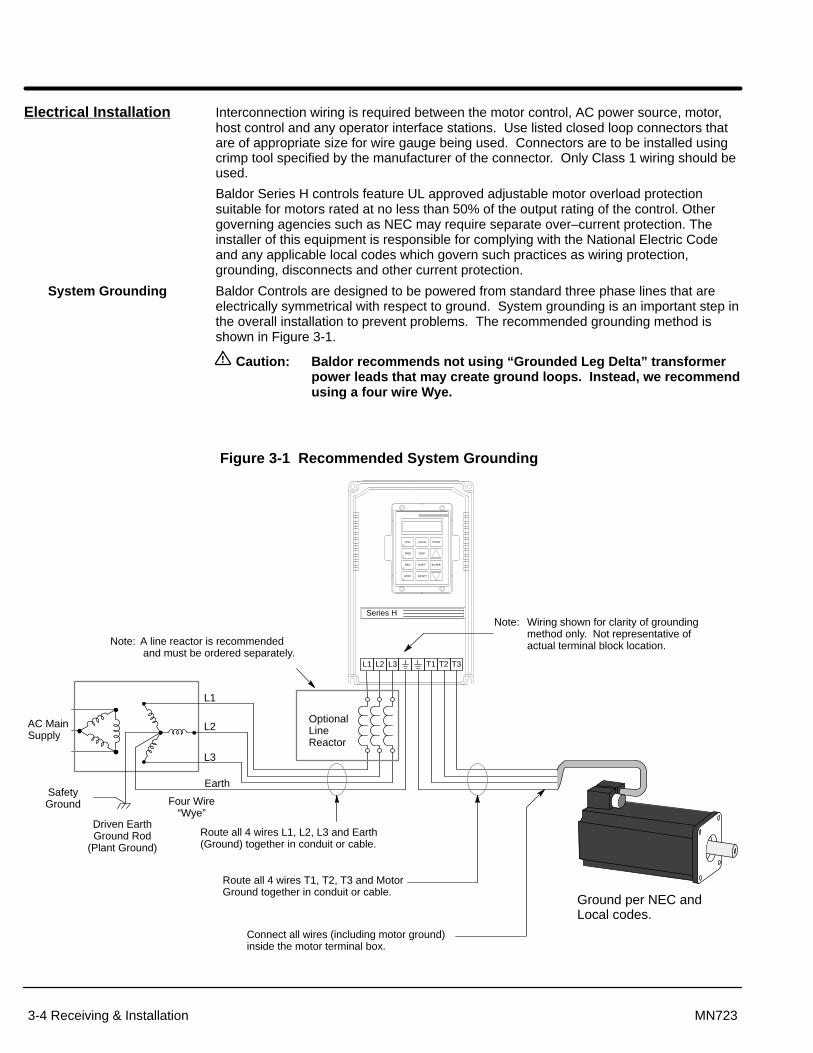
System Grounding Baldor Controls are designed to be powered from standard three phase lines that areelectrically symmetrical with respect to ground. System grounding is an important step inthe overall installation to prevent problems. The recommended grounding method isshown in Figure 3-1.
Caution: Baldor recommends not using “Grounded Leg Delta” transformerpower leads that may create ground loops. Instead, we recommendusing a four wire Wye.
Figure 3-1 Recommended System Grounding
L1
AC Main Supply
SafetyGround
Driven EarthGround Rod
(Plant Ground)
Four Wire“Wye”
L1
L2
L3
Earth
LOCAL
SHIFT
DISP
RESET
PROG
ENTER
JOG
STOP
REV
FWD
L2 L3 T1 T2 T3
Series H
OptionalLineReactor
Route all 4 wires L1, L2, L3 and Earth(Ground) together in conduit or cable.
Route all 4 wires T1, T2, T3 and MotorGround together in conduit or cable.
Connect all wires (including motor ground)inside the motor terminal box.
Ground per NEC and Local codes.
Note: Wiring shown for clarity of groundingmethod only. Not representative ofactual terminal block location.Note: A line reactor is recommended
and must be ordered separately.

Section 1General Information
Receiving & Installation 3-5MN723
Ungrounded Distribution SystemWith an ungrounded power distribution system it is possible to have a continuous currentpath to ground through the MOV devices. To avoid equipment damage, an Isolationtransformer with a grounded secondary is recommended. This provides three phase ACpower that is symmetrical with respect to ground.
Input Power ConditioningBaldor controls are designed for direct connection to standard three phase lines that areelectrically symmetrical with respect to ground. Certain power line conditions must beavoided. An AC line reactor or an isolation transformer may be required for some powerconditions.
Baldor Series H controls require a minimum line impedance of 3% for all sizesexcept C2. Size C2 controls require a 1% line impedance. Refer to “LineImpedance” for additional information.
If the feeder or branch circuit that provides power to the control haspermanently connected power factor correction capacitors, an input AC linereactor or an isolation transformer must be connected between the power factorcorrection capacitors and the control.
If the feeder or branch circuit that provides power to the control has powerfactor correction capacitors that are switched on line and off line, the capacitorsmust not be switched while the control is connected to the AC power line. If thecapacitors are switched on line while the control is still connected to the ACpower line, additional protection is required. TVSS (Transient Voltage SurgeSuppressor) of the proper rating must be installed between the AC line reactoror an isolation transformer and the AC input to the control.

3-6 Receiving & Installation MN723
Line Impedance The Baldor Series 23H control requires a minimum line impedance of 3% (voltage dropacross the reactor is 3% when the control draws rated input current) for all sizes exceptC2. Size C2 controls require a 1% line impedance. If the incoming power line has lessthan 3% impedance, a 3 phase line reactor can be used to provide the neededimpedance in most cases. Line reactors are optional and are available from Baldor.
The input impedance of the power lines can be determined in two ways:
Measure the line to line voltage at the motor at no load and at full rated load.Use these measured values to calculate impedance as follows:
%Impedance �(VoltsNo Load � VoltsFull Load)
(VoltsNo Load)� 100
Section 1General Information
Receiving & Installation 3-7MN723
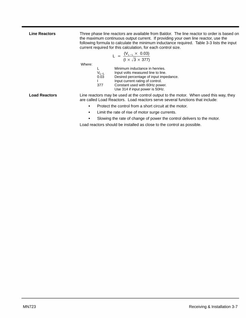
Line Reactors Three phase line reactors are available from Baldor. The line reactor to order is based onthe maximum continuous output current. If providing your own line reactor, use thefollowing formula to calculate the minimum inductance required. Table 3-3 lists the inputcurrent required for this calculation, for each control size.
L �(VL�L � 0.03)
(I � 3� � 377) Where:
L Minimum inductance in henries.VL–L Input volts measured line to line.0.03 Desired percentage of input impedance.I Input current rating of control.377 Constant used with 60Hz power.
Use 314 if input power is 50Hz.
Load Reactors Line reactors may be used at the control output to the motor. When used this way, theyare called Load Reactors. Load reactors serve several functions that include:
Protect the control from a short circuit at the motor.
Limit the rate of rise of motor surge currents.
Slowing the rate of change of power the control delivers to the motor.
Load reactors should be installed as close to the control as possible.

Section 1General Information
3-8 Receiving & Installation MN723
AC Main Circuit Considerations
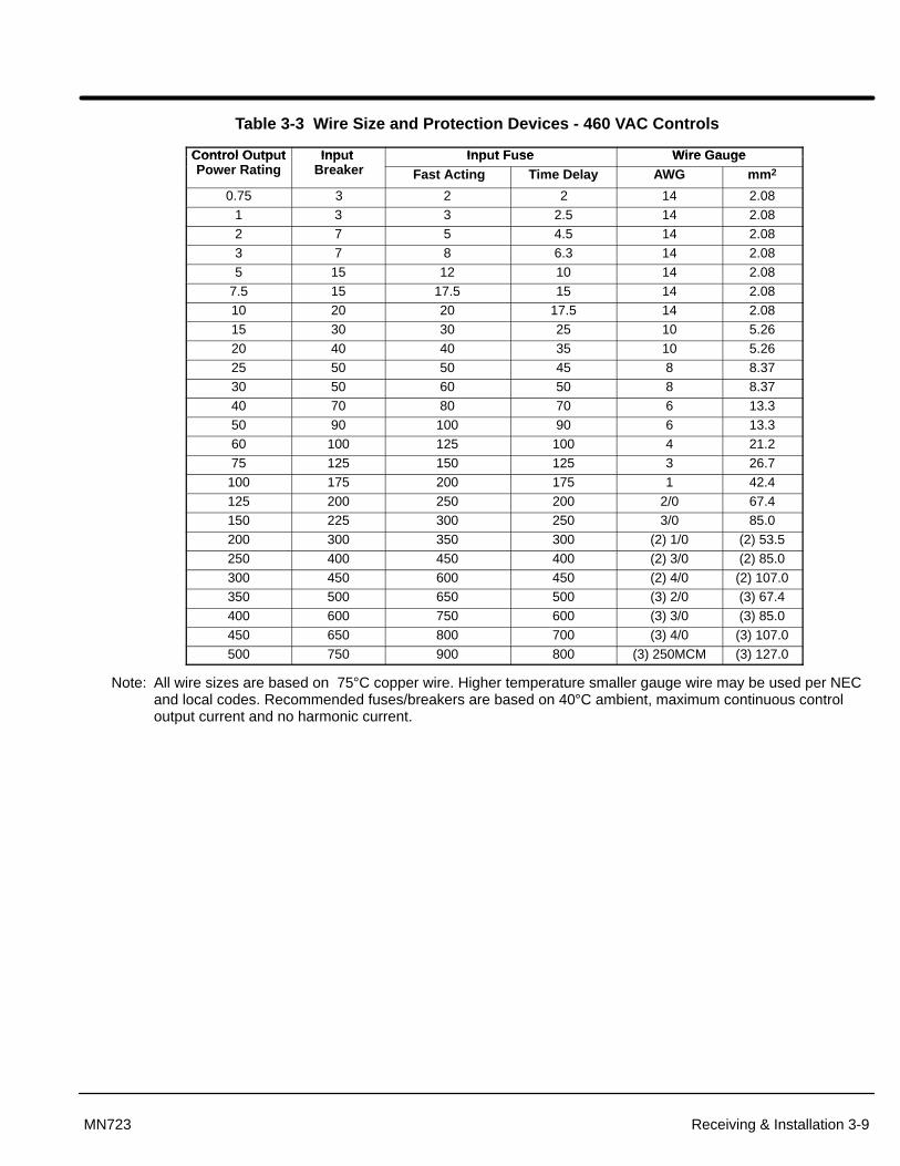
Protection Devices Be sure a suitable input power protection device is installed. Use the recommendedcircuit breaker or fuses listed in Tables 3-2 through 3-3 (Wire Size and ProtectionDevices). Input and output wire size is based on the use of copper conductor wire ratedat 75 °C. The table is specified for NEMA B motors.
Circuit Breaker: 1 phase, thermal magnetic. Equal to GE type THQ or TEB for 230 VAC
3 phase, thermal magnetic. Equal to GE type THQ or TEB for 230 VAC or GE type TED for 460 VAC.
Fast Action Fuses: 230 VAC, Buss KTN460 VAC, Buss KTS to 600A (KTU 601 - 1200A)
Very Fast Action: 230 VAC, Buss JJN 460 VAC, Buss JJS
Time Delay Fuses: 230 VAC, Buss FRN 460 VAC, Buss FRS to 600A (KTU 601 - 1200A)
Power Disconnect A power disconnect should be installed between the input power service and the controlfor a fail safe method to disconnect power. The control will remain in a powered-upcondition until all input power is removed from the control and the internal bus voltage isdepleted.
Wire Size and Protection Devices
Table 3-2 Wire Size and Protection Devices - 230 VAC Controls
Control O tp t Inp t F se Wire Ga geControl Output Inp t BreakerInput Fuse Wire GaugeControl Output
Power Rating Input BreakerFast Acting Time Delay AWG mm2
0.75 3 5 4 14 2.081 7 6 5 14 2.082 15 12 9 14 2.083 15 15 12 14 2.085 20 25 20 12 3.31
7.5 30 35 30 10 5.2610 40 45 35 10 5.2615 60 70 60 8 8.3720 70 80 70 6 13.325 90 100 90 4 21.230 100 125 110 4 21.240 150 175 150 2 33.650 175 200 175 1 42.460 200 225 200 1/0 53.575 250 300 250 3/0 85.0
Note: All wire sizes are based on 75°C copper wire. Higher temperature smaller gauge wire may be used per NECand local codes. Recommended fuses/breakers are based on 40°C ambient, maximum continuous controloutput current and no harmonic current.
Section 1General Information
Receiving & Installation 3-9MN723
Table 3-3 Wire Size and Protection Devices - 460 VAC Controls
Control O tp t Inp t Inp t F se Wire Ga geContro l OutputP R ti
Inpu t B k
Inpu t Fuse Wire GaugepPower Rating
pBreaker Fast Acting Time Delay AWG mm2
0.75 3 2 2 14 2.081 3 3 2.5 14 2.082 7 5 4.5 14 2.083 7 8 6.3 14 2.085 15 12 10 14 2.08
7.5 15 17.5 15 14 2.0810 20 20 17.5 14 2.0815 30 30 25 10 5.2620 40 40 35 10 5.2625 50 50 45 8 8.3730 50 60 50 8 8.3740 70 80 70 6 13.350 90 100 90 6 13.360 100 125 100 4 21.275 125 150 125 3 26.7100 175 200 175 1 42.4125 200 250 200 2/0 67.4150 225 300 250 3/0 85.0200 300 350 300 (2) 1/0 (2) 53.5250 400 450 400 (2) 3/0 (2) 85.0300 450 600 450 (2) 4/0 (2) 107.0350 500 650 500 (3) 2/0 (3) 67.4400 600 750 600 (3) 3/0 (3) 85.0450 650 800 700 (3) 4/0 (3) 107.0500 750 900 800 (3) 250MCM (3) 127.0
Note: All wire sizes are based on 75°C copper wire. Higher temperature smaller gauge wire may be used per NECand local codes. Recommended fuses/breakers are based on 40°C ambient, maximum continuous controloutput current and no harmonic current.

Section 1General Information
3-10 Receiving & Installation MN723
AC Line Connections
Reduced Input Voltage Derating All power ratings stated in Section 7 are for the stated nominal AC inputvoltages (230, 460 or 575VAC). The power rating of the control must be reduced whenoperating at a reduced input voltage. The amount of reduction is the ratio of the voltagechange.
Examples:
A 10HP, 230VAC control operating at 208VAC has a reduced power rating of 9.04HP.
10HP � 208VAC230VAC
� 9.04HP
Likewise, a 10HP, 460VAC control operating at 380VAC has a reduced power rating of8.26HP.
10HP � 380VAC460VAC
� 8.26HP
To obtain the full output rating of 10HP in either case requires a 15HP Control.
380-400 VAC Operation Size A, B and C2 460VAC controls may be used directly with a 380-400 VAC powersource, control modification is not necessary.
Size C, D, E, F and G 460VAC controls all require modification for operation on thereduced line voltage. Specifically, the control transformer must have the wire on terminal5 (for 460V) moved to terminal 4 (for 380-400V).
1. Be sure drive operation is terminated and secured.
2. Remove all power sources from the control. If power has been applied, wait atleast 5 minutes for bus capacitors to discharge.
3. Remove or open the front cover.
4. Remove the wire from terminal 5.
5. Place the wire that was removed from terminal 5 onto terminal 4.
6. Install or close the front cover.

Section 1General Information
Receiving & Installation 3-11MN723
Three Phase Motor and Control Connections The AC power and motor connections are shown in Figure 3-2. Overloads are notrequired. The 23H control has an electronic I2t motor overload protection. If motoroverloads are desired, they should be sized according to the manufacturers specificationsand installed between the motor and the T1, T2 and T3 terminals of the control.
Caution: Do not connect AC power to the Motor terminals T1, T2 and T3.Connecting AC power to these terminals may result in damage tothe control.
Caution: Baldor recommends not using “Grounded Leg Delta” transformerpower leads that may create ground loops. Instead, we recommendusing a four wire Wye.
1. Connect the incoming AC power wires from the protection devices to L1, L2and L3 at the main circuit terminals. The phase rotation is not important as thecontrol is not phase sensitive.
2. * Connect earth ground to the “ ” of the control. Be sure to comply with allapplicable codes.
3. Connect the three phase power leads of the AC motor to terminals T1, T2, andT3 of the main circuit terminals.
Note: Motors are phase sensitive. If the motor leads are labeled 1, 2, 3 then lead 1must be connected to T1 etc. If the motor leads are labeled U, V, W then leadU must be connected to T1 etc.
4. * Connect motor ground wire to the “ ” of the control. Be sure to comply withall applicable codes.
* Grounding by using conduit or panel connection is not adequate. A separateconductor of the proper size must be used as a ground conductor.

Section 1General Information
3-12 Receiving & Installation MN723
Figure 3-2 3 Phase AC Power and Motor Connections
Notes:
1. See “Protective Devices” described previously in this section.
2. Use same gauge wire for earth ground as is used for L1, L2 & L3.
3. Metal conduit should be used to shield wires (L1, L2, L3, T1, T2 and T3). If conduit is not used, be sure thatthe shield for the motor cable is connected to earth ground.
4. See “Line Impedance” described previously in this section.
5. See Line/Load Reactors described previously in this section.
6. See “M-Contactor” described in this section.
Optional Connection ofLoad Reactor and M-Contactor
L1 L2 L3
Alternate *Fuse
ConnectionNote 1
L1 L2 L3
L1 L2 L3
* CircuitBreaker
Earth
* Optional components not provided with 23H Control.
* AC Motor
See Recommended Tightening Torques in Section 7.
Note 3
BaldorSeries 23H
Control
*OptionalLine
Reactor
Note 1
Note 3
Note 3
*OptionalLoad
Reactor
Note 3
A1 B1 C1
A2 B2 C2
A1 B1 C1
A2 B2 C2
T1 T2 T3
Note 5
A1 B1 C1
Note 4
Note 3
*OptionalLoad
Reactor
Note 3
A1 B1 C1
A2 B2 C2
T1 T2 T3
Note 5
* Optional RC DeviceElectrocubeRG1781-3
T1
T2 T3
G
T1
T2 T3
G
789
*M Enable
J1
* Motor
M M M
* M-ContactorTo Power Source
(Rated Coil Voltage)
M=Contacts of optional M-Contactor
Note: Close “Enable” after “M” contact closure.
Note 6Note 6
Note 6
Note 2

Section 1General Information
Receiving & Installation 3-13MN723
Table 3-4 and 3-5 list the wire size for the input AC power wires. Motor leads should besized from the 3 phase data Tables 3-2 and 3-3.
Table 3-4 Single Phase Rating Wire Size and Protection Devices - 230 VAC Controls
Control OutputP R i
Input Breaker Input Fuse Input Wire GaugepPower Rating
pFast Acting Time Delay AWG mm2
0.75 10 10 9 14 2.081 10 12 10 14 2.082 15 20 17.5 14 2.083 25 25 25 12 3.315 40 45 35 10 5.26
7.5 50 60 50 8 8.3710 70 80 70 6 13.315 90 110 90 4 21.220 110 150 125 3 26.725 150 175 150 2 33.630 175 200 175 1/0 53.540 225 250 250 2/0 67.450 275 350 300 4/0 107.0
Note: All wire sizes are based on 75°C copper wire. Higher temperature smaller gauge wire may be used per NECand local codes. Recommended fuses/breakers are based on 40°C ambient, maximum continuous controloutput current and no harmonic current.
Table 3-5 Single Phase Rating Wire Size and Protection Devices - 460 VAC Controls
Control OutputP R i
Input Breaker Input Fuse Input Wire GaugepPower Rating
pFast Acting Time Delay AWG mm2
0.75 5 5 5 14 2.081 5 6 5.6 14 2.082 7.5 10 8 14 2.083 12.5 15 12 14 2.085 17.5 20 20 14 2.08
7.5 25 30 25 12 3.3110 40 40 30 10 5.2615 45 50 45 8 8.3720 60 70 60 8 8.3725 70 80 70 6 13.330 90 100 90 4 21.240 110 150 125 3 26.750 150 175 150 2 33.6
Note: All wire sizes are based on 75°C copper wire. Higher temperature smaller gauge wire may be used per NECand local codes. Recommended fuses/breakers are based on 40°C ambient, maximum continuous controloutput current and no harmonic current.

3-14 Receiving & Installation MN723
Single Phase Input Power Considerations
Caution: Do not connect AC power to the Motor terminals T1, T2 and T3.Connecting AC power to these terminals may result in damage tothe control.
Caution: Baldor recommends not using “Grounded Leg Delta” transformerpower leads that may create ground loops. Instead, we recommendusing a four wire Wye.
Single phase AC input power can be used to power the control instead of three phase forcontrol sizes A, B, C, C2, D, E and F. Single phase operation of G size controls is notpossible. The specifications and control sizes are listed in Section 7 of this manual. Ifsingle phase power is to be used, the rated Horsepower of the control may have to bereduced (derated). In addition, power wiring and jumper changes are required.
Single phase rating wire size and protection devices are listed in Tables 3-4 and 3-5.
Note: The 23H control has electronic I2t overload protection. If overloads aredesired, they should be sized according to the manufacturers specificationsand installed between the control output terminals T1, T2 and T3 and themotor.
Single Phase Control Derating: Single phase power derating requires that the continuous and peak current ratingsof the control be reduced by the following percentages:
1. 3-10A 230 and 2-5A 460 VAC controls:No derating required.
2. 15-28A (Size B) 230 and 8-15A 460 VAC controls:Derate HP by 40% of the nameplate rating.
3. 42-55A (Size C) and Larger 230 and 460 VAC controls:Derate HP by 50% of the nameplate rating.

Receiving & Installation 3-15MN723
Size A, B and C2 Single Phase Power InstallationJumper Configuration
Size A, B and C2 controls, no jumper changes required.
Power and Control ConnectionsThe single phase power and motor connections are shown in Figure 3-3.
1. Connect the incoming power wires to Main Circuit Terminals L1 and L2.
2. Place a jumper across control power input terminals L2 and L3. Use the samesize wire for the jumper as the incoming power wires on L1 and L2.
3. Connect earth ground to the “ ” of the control. Be sure to comply with localcodes.
4. Connect the three phase power leads of the AC motor to terminals T1, T2, andT3 of the Main Circuit Terminals.
Note: Motors are phase sensitive. If the motor leads are labeled 1, 2, 3 then lead 1must be connected to T1 etc. If the motor leads are labeled U, V, W then leadU must be connected to T1 etc.
5. Connect motor ground wire to the “ ” of the control. Be sure to comply with allapplicable codes.
Note: In steps 3 and 5 grounding by using conduit or panel connection is notadequate. A separate conductor of the proper size must be used as a groundconductor.

Section 1General Information
3-16 Receiving & Installation MN723
Figure 3-3 Size A, B & C2 Single Phase 230/460VAC Power and Motor Connections
Notes:
1. See “Protective Devices” described previously in this section.
2. Use same gauge wire for earth ground as is used for L1, L2 &L3.
3. Metal conduit should be used to shield wires (L1, L2, L3, T1, T2 and T3). If conduit is not used, be sure thatthe shield for the motor cable is connected to earth ground.
4. See “Line Impedance” described previously in this section.
5. See Line/Load Reactors described previously in this section.
6. See “M-Contactor” described in this section.
Optional Connection ofLoad Reactor and M-Contactor
L1 L2
* FuseConnection Note 1
L1 L2
L1 L2 L3
* CircuitBreaker
Earth
* Optional components not provided with 23H Control.
* AC Motor
See Recommended Tightening Torques in Section 7.
Note 3
BaldorSeries 23H
Control
*OptionalLine
Reactor
Note 1
Note 3
Note 3
*OptionalLoad
Reactor
Note 3
A1 B1 C1
A2 B2 C2
A1 B1
A2 B2
T1 T2 T3
Note 5
A1 B1
Note 4
Note 3
*OptionalLoad
Reactor
Note 3
A1 B1 C1
A2 B2 C2
T1 T2 T3
Note 5
* Optional RC DeviceElectrocubeRG1781-3
T1
T2 T3
G
T1
T2 T3
G
789
*M Enable
J1
* Motor
M M M
* M-ContactorTo Power Source(Rated Coil
Voltage)
M=Contacts of optional M-Contactor
Note: Close “Enable” after “M” contact closure.
Note 6Note 6
Note 6
Note 2

Receiving & Installation 3-17MN723
Size C and D Single Phase Power InstallationJumper Configuration Place JP2 on pins 1 & 2 for control single phase operation. Place JP3 in position B for fan single phase operation.
J2J3 J1 J5
J14J12
J13
JP3A
B
AC INPUT
R58
R36
R35
R27
R24
JP1
1
1
JP2
JP3 Position A = Three PhasePosition B = Single Phase
8380
Gate Drive Circuit Board
JP2 Pins 1 & 2 = Single PhasePins 2 & 3 = Three Phase
Power and Control ConnectionsThe single phase power and motor connections are shown in Figure 3-3.
1. Connect the incoming power wires to Main Circuit Terminals L2 and L3.
2. Place a jumper across control power input terminals L1 and L2. Use the samesize wire for the jumper as the incoming power wires on L2 and L3.
3. Connect earth ground to the “ ” of the control. Be sure to comply with localcodes.
4. Connect the three phase power leads of the AC motor to terminals T1, T2, andT3 of the Main Circuit Terminals.
Note: Motors are phase sensitive. If the motor leads are labeled 1, 2, 3 then lead 1must be connected to T1 etc. If the motor leads are labeled U, V, W then leadU must be connected to T1 etc.
5. Connect motor ground wire to the “ ” of the control. Be sure to comply with allapplicable codes.
Note: In steps 3 and 5 grounding by using conduit or panel connection is notadequate. A separate conductor of the proper size must be used as a groundconductor.
Section 1General Information
3-18 Receiving & Installation MN723
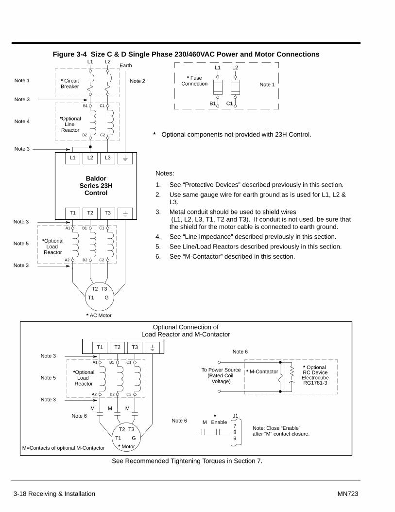
Figure 3-4 Size C & D Single Phase 230/460VAC Power and Motor Connections
Notes:
1. See “Protective Devices” described previously in this section.
2. Use same gauge wire for earth ground as is used for L1, L2 &L3.
3. Metal conduit should be used to shield wires (L1, L2, L3, T1, T2 and T3). If conduit is not used, be sure thatthe shield for the motor cable is connected to earth ground.
4. See “Line Impedance” described previously in this section.
5. See Line/Load Reactors described previously in this section.
6. See “M-Contactor” described in this section.
Optional Connection ofLoad Reactor and M-Contactor
L1 L2
* FuseConnection Note 1
L1 L2
L1 L2 L3
* CircuitBreaker
Earth
* Optional components not provided with 23H Control.
* AC Motor
See Recommended Tightening Torques in Section 7.
Note 3
BaldorSeries 23H
Control
*OptionalLine
Reactor
Note 1
Note 3
Note 3
*OptionalLoad
Reactor
Note 3
A1 B1 C1
A2 B2 C2
B1 C1
B2 C2
T1 T2 T3
Note 5
B1 C1
Note 4
Note 3
*OptionalLoad
Reactor
Note 3
A1 B1 C1
A2 B2 C2
T1 T2 T3
Note 5
* Optional RC DeviceElectrocubeRG1781-3
T1
T2 T3
G
T1
T2 T3
G
789
*M Enable
J1
* Motor
M M M
* M-ContactorTo Power Source(Rated Coil
Voltage)
M=Contacts of optional M-Contactor
Note: Close “Enable” after “M” contact closure.
Note 6Note 6
Note 6
Note 2

Receiving & Installation 3-19MN723
Size E Single Phase Power InstallationJumper Configuration
Place JP1 on the High Voltage Circuit Board across pins 1 and 2.
JP1
1
JP2
J7
J8
J2 A
C IN
PU
TC
NT
RL
XF
MR
400V
PR
ID
UA
L 23
0VFA
NS
SIN
GLE
230V
FA
NS
CN
TR
L X
FM
R46
0V P
RI
1
High Voltage Circuit Board(100 - 150HP E Size)
8470
JP1Pins 1 & 2 = Single PhasePins 2 & 3 = Three Phase
Power and Control ConnectionsThe single phase power and motor connections are shown in Figure 3-5.
1. Connect the incoming power wires to Main Circuit Terminals L1 and L2.
2. Place a jumper across control power input terminals L2 and L3. Use the samesize wire for the jumper as the incoming power wires on L1 and L2.
3. Connect earth ground to the “ ” of the control. Be sure to comply with localcodes.
4. Connect the three phase power leads of the AC motor to terminals T1, T2, andT3 of the Main Circuit Terminals.
Note: Motors are phase sensitive. If the motor leads are labeled 1, 2, 3 then lead 1must be connected to T1 etc. If the motor leads are labeled U, V, W then leadU must be connected to T1 etc.
5. Connect motor ground wire to the “ ” of the control. Be sure to comply with allapplicable codes.
Note: In steps 3 and 5 grounding by using conduit or panel connection is notadequate. A separate conductor of the proper size must be used as a groundconductor.

Section 1General Information
3-20 Receiving & Installation MN723
Figure 3-5 Size E Single Phase 230/460VAC Power and Motor Connections
Notes:
1. See “Protective Devices” described previously in this section.
2. Use same gauge wire for earth ground as is used for L1, L2 & L3
3. Metal conduit should be used to shield wires (L1, L2, L3, T1, T2 and T3). If conduit is not used, be sure thatthe shield for the motor cable is connected to earth ground.
4. See “Line Impedance” described previously in this section.
5. See Line/Load Reactors described previously in this section.
6. See “M-Contactor” described in this section.
Optional Connection ofLoad Reactor and M-Contactor
L1 L2
* FuseConnection Note 1
L1 L2
L1 L2 L3
* CircuitBreaker
Earth
* Optional components not provided with 23H Control.
* AC Motor
See Recommended Tightening Torques in Section 7.
Note 3
BaldorSeries 23H
Control
*OptionalLine
Reactor
Note 1
Note 3
Note 3
*OptionalLoad
Reactor
Note 3
A1 B1 C1
A2 B2 C2
A1 B1
A2 B2
T1 T2 T3
Note 5
A1 B1
Note 4
Note 3
*OptionalLoad
Reactor
Note 3
A1 B1 C1
A2 B2 C2
T1 T2 T3
Note 5
* Optional RC DeviceElectrocubeRG1781-3
T1
T2 T3
G
T1
T2 T3
G
789
*M Enable
J1
* Motor
M M M
* M-ContactorTo Power Source(Rated Coil
Voltage)
M=Contacts of optional M-Contactor
Note: Close “Enable” after “M” contact closure.
Note 6Note 6
Note 6
Note 2

Receiving & Installation 3-21MN723
Size F Single Phase Power InstallationJumper Configuration Place JP2 on the High Voltage Circuit Board across pins 1 and 2.
J2
J1 J1J3JP1
1
JP2
J5
High Voltage Circuit Board(150 - 250HP F Size)
Power and Control ConnectionsThe single phase power and motor connections are shown in Figure 3-6.
1. Connect the incoming power wires to Main Circuit Terminals L2 and L3.
2. Place a jumper across control power input terminals L1 and L3. Use the samesize wire for the jumper as the incoming power wires on L2 and L3.
3. Connect earth ground to the “ ” of the control. Be sure to comply with localcodes.
4. Connect the three phase power leads of the AC motor to terminals T1, T2, andT3 of the Main Circuit Terminals.
Note: Motors are phase sensitive. If the motor leads are labeled 1, 2, 3 then lead 1must be connected to T1 etc. If the motor leads are labeled U, V, W then leadU must be connected to T1 etc.
5. Connect motor ground wire to the “ ” of the control. Be sure to comply with allapplicable codes.
Note: In steps 3 and 5 grounding by using conduit or panel connection is notadequate. A separate conductor of the proper size must be used as a groundconductor.

Section 1General Information
3-22 Receiving & Installation MN723
Figure 3-6 Size F Single Phase 230/460VAC Power and Motor Connections
Notes:
1. See “Protective Devices” described previously in this section.
2. Use same gauge wire for earth ground as is used for L1, L2 &L3.
3. Metal conduit should be used to shield wires (L1, L2, L3, T1, T2 and T3). If conduit is not used, be sure thatthe shield for the motor cable is connected to earth ground.
4. See “Line Impedance” described previously in this section.
5. See Line/Load Reactors described previously in this section.
6. See “M-Contactor” described in this section.
Optional Connection ofLoad Reactor and M-Contactor
L1 L2
* FuseConnection Note 1
L1 L2
L1 L2 L3
* CircuitBreaker
Earth
* Optional components not provided with 23H Control.
* AC Motor
See Recommended Tightening Torques in Section 7.
Note 3
BaldorSeries 23H
Control
*OptionalLine
Reactor
Note 1
Note 3
Note 3
*OptionalLoad
Reactor
Note 3
A1 B1 C1
A2 B2 C2
B1 C1
B2 C2
T1 T2 T3
Note 5
B1 C1
Note 4
Note 3
*OptionalLoad
Reactor
Note 3
A1 B1 C1
A2 B2 C2
T1 T2 T3
Note 5
* Optional RC DeviceElectrocubeRG1781-3
T1
T2 T3
G
T1
T2 T3
G
789
*M Enable
J1
* Motor
M M M
* M-ContactorTo Power Source(Rated Coil
Voltage)
M=Contacts of optional M-Contactor
Note: Close “Enable” after “M” contact closure.
Note 6Note 6
Note 60
Note 2

Section 1General Information
Receiving & Installation 3-23MN723
Optional Dynamic Brake Hardware
WARNING: Resistors may generate enough heat to ignite combustiblematerials. To avoid fire hazard, keep all combustible materials andflammable vapors away from brake resistors.
Physical Installation Dynamic Brake (DB) hardware must be installed on a flat, non-flammable, vertical surfaceto obtain effective cooling and operation. The ambient temperature must not exceed80°C.
1. Select a clean VERTICAL surface that is free from corrosive gasses, liquids,vibration, dust and metallic particles.
Caution: If the DB hardware mounting is in any position other than vertical(Figure 3-7), the DB hardware must be derated by 35% of its wattagerating. (The value of the Level 2 Brake Adjust block, Resistor Wattsparameter must not exceed 65% of the wattage value stated on theresistor nameplate).
2. Mount the DB hardware as shown in Figure 3-7.
Figure 3-7 DB Hardware Installation
ÉÉÉÉÉÉÉÉÉÉÉÉÉÉÉÉÉÉÉÉÉÉÉÉÉÉÉÉÉÉÉÉÉÉ
Maximum temperaturesnear wall. Maximum temperatures
above the enclosure.
80°C
70°C
65°C
70°C
75°C
Heat shield inside RBA units mustbe in this vertical direction toprotect transistor and circuit board.
48″
36″
24″12″
85°C
115°C
115°C
200°C

Section 1General Information
3-24 Receiving & Installation MN723
Electrical Installation Terminal connections for DB hardware are determined by 23H Control model numbersuffix (E, EO, ER or MO). See Figure 3-8 for terminal identification.
Figure 3-8 DB Terminal Identification
“E” or “W” suffix (SD23HXXX-E).
R2 B+/R1 B– GND
“EO” or “MO” suffix (SD23HXXX-EO).
B+ B– GND D1 D2
“ER” suffix (SD23HXXX-ER).
B+/R1 R2 GND
See recommended Terminal Tightening Torques in Section 7.
Size C2 “EO” suffix
B+ B–
Size C2 “ER” suffix
R2 B+ B–
Figure 3-9 Wiring for RGA Assembly (-E, -W and -ER controls)
See recommended Terminal Tightening Torques in Tables 3-6, 3-8 and in Section 7.
Optional Customer SuppliedBreaker or Fuse Protection -
Subject to Local Codes
MOTOR
50/60 Hz3 PhasePower
GND
R2
B+/R1
T3
T2
T1
L3
L2
L1
GND
GNDT1T2
T3
OptionalDynamic Brake
(RGA)
ControlTerminals DB
Terminals
R2
R1
For C2 Only
GND
R2
B+
OptionalDynamic Brake
(RGA)
DBTerminals
R2
R1
B-
Note: Although not shown, metal conduit should be used to shield all power wiresand motor leads.

Section 1General Information
Receiving & Installation 3-25MN723
Figure 3-10 Wiring for RBA Assembly
Optional Customer SuppliedBreaker or Fuse Protection -
Subject to Local Codes
* MOTOR
50/60 Hz3 PhasePower
GND
B–
B+
T3
T2
T1
L3
L2
L1
GND
GNDT1T2
T3
OptionalDynamic
Brake(RBA)
D1
D2
D1
D2
B–
B+
Shielded Twisted Pair
See recommended Terminal Tightening Torques in Tables 3-7,3-8 and Section 7.
Transistor/ Resistor
Assembly
* Optional
For C2 Only
GND
B-
B+
DBTerminals
R2
B–
B+
Note: Although not shown, metal conduit should be used to shield all power wiresand motor leads.
Figure 3-11 Wiring for RTA Assembly
Optional Customer SuppliedBreaker or Fuse Protection -
Subject to Local Codes
* MOTOR
50/60 Hz3 PhasePower
GND
B–
B+
T3
T2
T1
L3
L2
L1
GND
GNDT1T2
T3
OptionalDynamic
Brake(RTA)
D1
D2
D1
D2
B–
B+
R2R1
R2R1
OptionalRGA
Assembly
Shielded Twisted Pair
ResistorAssembly
TransistorAssembly
* Optional
See recommended Terminal Tightening Torques in Tables 3-7,3-8 and Section 7.
For C2 Only
GND
B-
B+
DBTerminals
R2
B–
B+
Note: Although not shown, metal conduit should be used to shield all power wiresand motor leads.
Section 1General Information
3-26 Receiving & Installation MN723
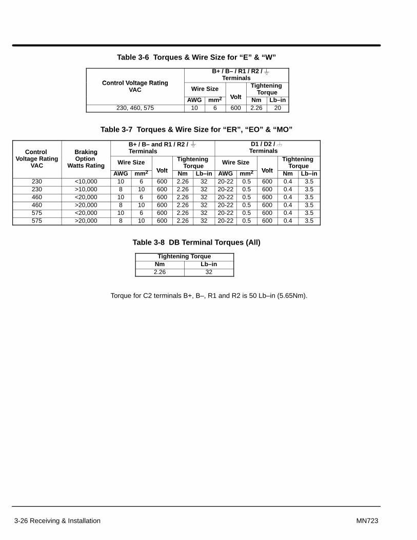
Table 3-6 Torques & Wire Size for “E” & “W”
Control Voltage Rating
B+ / B– / R1 / R2 /Terminals
Control Voltage RatingVAC Wire Size
Volt
Tightening Torque
AWG mm2 Volt Nm Lb–in230, 460, 575 10 6 600 2.26 20
Table 3-7 Torques & Wire Size for “ER”, “EO” & “MO”
Control BrakingB+ / B– and R1 / R2 / Terminals
D1 / D2 / TerminalsControl
Voltage RatingVAC
BrakingOption
Watts Rating Wire SizeVolt
Tightening Torque Wire Size
Volt
Tightening Torqueg
AWG mm2 Volt Nm Lb–in AWG mm2 Volt Nm Lb–in230 <10,000 10 6 600 2.26 32 20-22 0.5 600 0.4 3.5230 >10,000 8 10 600 2.26 32 20-22 0.5 600 0.4 3.5460 <20,000 10 6 600 2.26 32 20-22 0.5 600 0.4 3.5460 >20,000 8 10 600 2.26 32 20-22 0.5 600 0.4 3.5575 <20,000 10 6 600 2.26 32 20-22 0.5 600 0.4 3.5575 >20,000 8 10 600 2.26 32 20-22 0.5 600 0.4 3.5
Table 3-8 DB Terminal Torques (All)
Tightening TorqueNm Lb–in2.26 32
Torque for C2 terminals B+, B–, R1 and R2 is 50 Lb–in (5.65Nm).

Section 1General Information
Receiving & Installation 3-27MN723
M-Contactor If required by local codes or for safety reasons, an M-Contactor (motor circuit contactor)may be installed. However, incorrect installation or failure of the M-contactor or wiringmay damage the control.
Caution: If an M-Contactor is installed, the control must be disabled for atleast 20msec before the M-Contactor is opened. If the M-Contactoris opened while the control is supplying voltage and current to themotor, the control may be damaged.
A motor circuit contactor provides a positive disconnect of the motor windings from thecontrol. Opening the M-Contactor ensures that the control cannot drive the motor. This maybe required during certain manual operations (like cleaning cutting knives etc.). Figure 3-2shows how an M-Contactor is connected to the H series control.
Resolver Feedback The resolver connections are made at the J1 connector as shown in Figure 3-12. Theresolver cable must be shielded twisted pair #22 AWG (0.34mm2) wire minimum. Thecable must also have an overall shield and not exceed 150 feet (45m) in length.Maximum wire-to-wire or wire-to-shield capacitance is 50pf per foot (maximum of 7500pffor 150 ft). See electrical noise considerations in Section 5 of this manual.
Resolver wiring must be separated from power wiring. Separate parallel runs of resolverand power cables by at least 3″. Cross power wires at right angles only. Insulate or tapeungrounded end of shields to prevent contact with other conductors or ground.
Caution: Do not connect any shields to the motor frame. At a minimum,resolver signal integrity will be compromised and damage to thecontrol may result. The resolver shields must be connected atJ1-28 only.
1. Connect the SINE+ to J1-23 and SINE– to J1-24.
2. Connect the COSINE+ to J1-25 and COSINE– to J1-26.
3. Connect the EXCITATION+ to J1-27 and EXCITATION– to J1-28.
4. Connect the SHIELD wire to J1-28 EXCITATION – (analog ground).
Figure 3-12 Resolver Cable Connections
P
23 SINE+
24 SINE–
25 COSINE+
26 COSINE–
27 EXCITATION +
28 EXCITATION –
29 INDEX
P
P
P
= Twisted Pair
R2
R1
S2
S4
S1S3
J1
See recommended Terminal Tightening Torques in Section 7.
30 COMMON
Figure 3-13 Baldor Resolver Cable Lead IdentificationRed EXCITATION+Blue EXCITATION–Green COSINE+Shield EXCITATION–Yellow COSINE–Pink SINE+Gray SINE–

Section 1General Information
3-28 Receiving & Installation MN723
Simulated Encoder Output The control provides a simulated encoder output at connector J1 as shown in Figure3-14. This output provides position information to the host controller. Use twisted pairwire with an overall shield.
This output simulates a 1024 ppr encoder with quadrature outputs. Counting inquadrature will provide 4096 ppr with one index marker (CHC) per revolution. It isrecommended that this output only drive one circuit load. Driving multiple loads is notrecommended (to avoid ground loops).
Figure 3-14 Simulated Encoder Output
31
32
33
34
35
36
38 DGND
C
C
B
B
A
AJ1
To Host PositionController
P
= Twisted Pair
P
P
P
See recommended Terminal Tightening Torques in Section 7.
26LS31
AABBCC
IN BIN CIN D
IN AFromProcessor
1. Connect J1-31 and J1-32 outputs to Host Position Controller Channel A inputs.
2. Connect J1-33 and J1-34 outputs to Host Position Controller Channel B inputs.
3. Connect J1-35 and J1-36 outputs to Host Position Controller Channel C inputs.
4. Connect the cable shields to J1-38.

Receiving & Installation 3-29MN723
Home (Orient) Switch Input To use the internally generated index pulse for homing, no external connections arerequired. However, to use an external index input a jumper must be moved and theexternal index signal must be connected to J1-29 and 30.
External Index Jumper
Refer to Figure 3-28. The resolver feedback module must be removed from the maincontrol board to change the JP1 position. Use the following procedure.
1. Use a grounded wrist strap.
2. Firmly grasp the Resolver Feedback Module and remove it from its connectorson the main control board. Be careful not to bend the pins by twisting or liftingthe module unevenly.
3. Place the jumper in the desired position, refer to Figure 3-28.
4. Insert the Resolver Feedback Module back into its connectors on the maincontrol board. Be careful not to bend the pins by twisting or lifting the moduleunevenly. Be sure the module is fully seated (pushed into) the connectors.
Connections for External Index Signal
The Home or Orient function causes the motor shaft to rotate to a predefined homeposition. The homing function allows shaft rotation in the drive forward direction only.The home position is located when a machine mounted switch or “Index” pulse isactivated (closed). Home is defined by a rising signal edge at terminal J1-29. The shaftwill continue to rotate only in a “Drive Forward” direction for a user defined offset value.The offset is programmed in the Level 2 Miscellaneous Homing Offset parameter. Thespeed at which the motor will “Home” or orient is set with the Level 2 MiscellaneousHoming Speed parameter.
A machine mounted switch may be used to define the Home position or “index” channel.A differential line driver output from a solid state switch is preferred for best noiseimmunity. Connect this differential output to terminals J1-29 and J1-30.
A single ended solid-state switch or limit switch should be wired as shown in Figure 3-15.Regardless of the type of switch used, clean rising and falling edges at J1-29 are requiredfor accurate positioning.
Note: Control requires dynamic brake hardware for Orient (Homing) function towork. Control will trip without dynamic brake hardware installed. Size A and Bcontrols ( “–E” suffix) are shipped with factory installed dynamic brakehardware.
Figure 3-15 Typical Home or Orient Switch Connections
29
30 Common
INDEX
J1
Limit Switch (Closed at HOME).
See recommended Terminal Tightening Torques in Section 7.
Customer Provided+5VDC to +12VDC

3-30 Receiving & Installation MN723
Control Circuit Connections Ten operating modes are available in the Series 23H Control. These operating modesdefine the basic motor control setup and the function of the input and output terminals.After the circuit connections are completed, the operating mode is selected byprogramming the Operating Mode parameter in the Level 1 Input programming Block.Available operating modes include:
• Keypad Control
• Standard Run, 3 Wire Control
• 15 Speed, 2 Wire Control
• 3SPD ANA 2 WIRE
• 3SPD ANA 3 WIRE
• Serial
• Bipolar Speed
• Process Control
• EPOT – 2 WIRE
• EPOT – 3 WIRE
Note: The Serial operating mode requires one of the optional Serial Interfaceexpansion boards (RS232 or 422/485). Installation and operation informationfor these serial expansion boards is provided in Serial Communicationsexpansion board manual MN1310. This manual is shipped with the serialexpansion boards.
Keypad Operating Mode (see Figure 3-16)
The Keypad operating mode allows the control to be operated from the keypad. In thismode no control connection wiring is required. However, the Enable, Stop and ExternalTrip inputs may optionally be used. All other opto inputs remain inactive. However, theanalog outputs and opto-outputs remain active at all times. To use one of the three optoinputs, you must set the associated parameter value.
For operation in Keypad mode, set the Level 1 Input block, Operating mode parameter toKeypad. At the keypad press the LOCAL key to change between the LOCAL andREMOTE modes. The word “LOCAL” or “Remote” should appear on the keypad display.
The STOP key can operate in either of two ways:
Press STOP key one time to brake or coast to stop (as set in the Level 1Keypad Setup block, Keypad Stop Mode parameter).
Press STOP key two times to disable control.
To use the Enable input, J1-8 must be connected and the Local Enable INP parameter inthe Level 2 Protection block must be set to ON. The Enable line is normally closed.When opened, the motor will COAST to a stop. When the enable line is again closed, themotor will not start until a new direction command is received from the keypad ( or �key).
To use the Stop input, J1-8 must be connected and the Level 1 Keypad Setup block,LOC. Hot Start parameter must be set to ON. The Stop line is normally closed. Whenopened, the motor will COAST or REGEN to a stop depending upon the setting of Level 1Keypad Setup block Keypad Stop Key parameter value. Closing the input willimmediately start the motor.
The External Trip input is used to cause a fault condition during a motor over temperaturecondition. The External Trip input (J1-16) must be connected and the External Tripparameter in the Level 2 Protection block must be set to ON. When J1-16 is opened, themotor will coast to a stop and an External Trip fault is displayed on the keypad.

Section 1General Information
Receiving & Installation 3-31MN723
Figure 3-16 Keypad Control Connection Diagram
8
9
10
11
12
13
14
15
16
17
18
19
20
21
22
ENABLE
INPUT #1
INPUT #2
STOP
INPUT #4
INPUT #5
EXTERNAL TRIP
OPTO INPUT COMMON
Programmable 0–5v Output (Factory Preset: Speed)
J1ANALOG GND
ANALOG INPUT 1
POT REFERENCE
ANALOG INPUT +2
ANALOG INPUT –2
ANALOG OUT 1
ANALOG OUT 2
OPTO OUT #1
OPTO OUT #2
OPTO OUT #3
OPTO OUT #4
No ConnectionsRequired
1
2
3
4
5
6
7Programmable 0–5v Output (Factory Preset: Current)
See recommended Terminal Tightening Torques in Section 7.
30
31
32
33
34
35
36
37
38
39
40
41
42
43
44
23
24
25
26
27
28
29
Note 2
+24VDC
OPTO IN POWER
OPTO OUT #1 RETURN
OPTO OUT #2 RETURN
OPTO OUT #3 RETURN
OPTO OUT #4 RETURN
INPUT #1
INPUT #7
6
Note 1
Notes:
1. Refer to Analog Outputs.
2. Refer to Opto Isolated Outputs.
3. Refer to Resolver Feedback.
4. Refer to Incremental Position Output.
SINE +
SINE –
COSINE +
COSINE –
EXCITATION +
EXCITATION –
INDEX
COMMON
A
A
B
B
C
C
NO CONNECTION
COMMON
Note 3
Note 4
Refer to Figure 3-30.
No Connections
No Connections
J1-8 Optional Enable input (not required).OPEN disables the control and motor coasts to a stop if Level 1 KEYPAD block, LocalEnable INP parameter is set to “ON”. CLOSED allows current to flow in the motor.
J1-11 Optional STOP input (not required).OPEN disables the control and motor coasts or brakes to a stop if Level 1 KEYPADblock, LOCAL HOT START parameter is set to “ON”. Motor will restart whenswitch closes after open.CLOSED allows current to flow in the motor.
J1-16 Optional External Trip input (not required).OPEN causes an External Trip to be received by the control (when programmed to“ON”). When this occurs, the drive disables, drive “Ready” LED goes out and an externaltrip fault is displayed on the keypad display (also logged into the fault log). If J1-16 is connected, you must set Level 2 Protection block, External Trip to “ON” torecognize the J1-16 input.
J1-39 & Jumper as shown to power the Opto Inputs from the internal +24VDC supply.40

Section 1General Information
3-32 Receiving & Installation MN723
Standard Run 3 Wire Mode ConnectionsIn standard run mode, the control is operated by the Opto Isolated inputs at J1-8 throughJ1-16 and the analog command input. The Opto inputs can be switches as shown inFigure 3-17 or logic signals from another device. The External Trip Opto Input at J1-16is active if connected as shown and the Level 2 Protection block, External Trip parameteris set to ON.
The motor speed command may be one of the following:Preset Speed (J1-14)Command Input (Potentiometer, 0-5VDC or 0-10VDC)Differential analog input (±5VDC, ±10VDC or 4-20mA)
Make control connections as shown in Figure 3-17.

Section 1General Information
Receiving & Installation 3-33MN723
Figure 3-17 Standard Run 3-Wire Connection Diagram
PRESET SPEED #1
8
9
10
11
12
13
14
15
16
17
18
19
20
21
22
ENABLE
FORWARD RUN
REVERSE RUN
STOP
JOG
ACCEL/DECEL
EXTERNAL TRIP
OPTO INPUT COMMON
Programmable 0–5v Output (Factory Preset: Speed)
J1ANALOG GND
ANALOG INPUT 1
POT REFERENCE
ANALOG INPUT +2
ANALOG INPUT –2
ANALOG OUT 1
ANALOG OUT 2
OPTO OUT #1
OPTO OUT #2
OPTO OUT #3
OPTO OUT #4
1
2
3
4
5
6
7Programmable 0–5v Output (Factory Preset: Current)
See recommended Terminal Tightening Torques in Section 7.
30
31
32
33
34
35
36
37
38
39
40
41
42
43
44
23
24
25
26
27
28
29
+24VDC
OPTO IN POWER
OPTO OUT #1 RETURN
OPTO OUT #2 RETURN
OPTO OUT #3 RETURN
OPTO OUT #4 RETURN
FAULT RESET
Note 3
Notes 1 and 2
Note 5
0-10VDC or5k� Command PotNote 1
Unipolar 0-5 or 0-10VDC, 4-20mA
Notes:
1. Refer to Analog Inputs.
2. Refer to Figure 3-28 for 4-20mA.
3. Refer to Analog Outputs.
4. Refer to Opto Isolated Inputs.
5. Refer to Opto Isolated Outputs.
6. Refer to Resolver Feedback.
7. Refer to Incremental Position Output.
Note 4
SINE +
SINE –
COSINE +
COSINE –
EXCITATION +
EXCITATION –
A
A
B
B
C
C
NO CONNECTION
COMMON
Note 6
Note 7
Refer to Figure 3-30.
INDEX
COMMON
J1-8 OPEN disables the control and motor coasts to a stop. CLOSED allows current to flow in the motor and produce torque.
J1-9 MOMENTARY CLOSED starts motor operation in the Forward direction. In JOG mode(J1-12 CLOSED), hold J1-9 CLOSED jogs motor in the Forward direction.
J1-10 MOMENTARY CLOSED starts motor operation in the Reverse direction. In JOG mode(J1-12 CLOSED), hold J1-10 CLOSED JOGS motor in the Reverse direction.
J1-11 MOMENTARY OPEN causes motor to stop. Motor current continues to be applied to themotor.
J1-12 CLOSED places control in JOG mode, Forward (J1-9) and Reverse Run (J1-10) areused to jog the motor.
J1-13 OPEN selects ACC / DEC / S-CURVE group 1. CLOSED selects group 2.
J1-14 CLOSED selects preset speed #1, (J1-12 JOG, will override this preset speed).OPEN allows speed command as selected in the command select parameter.
J1-15 CLOSED to reset fault condition,OPEN to run.
J1-16 OPEN causes an external trip to be received by control. The control will disable anddisplay external trip when programmed “ON”. When this occurs, the drive is disabledand an external trip fault is displayed on the keypad display (also logged into the faultlog). If J1-16 is connected, you must set Level 2 Protection block, External Trip to “ON”.
J1-39 & 40 Jumper as shown to power the Opto Inputs from the internal +24VDC supply.

Section 1General Information
3-34 Receiving & Installation MN723
15 Speed 2-Wire Mode Connections Switch Truth Table is defined in Table 3-9.
Operation in the 15 Speed 2-Wire mode is controlled by the Opto Isolated inputs at J1-8through J1-16. The Opto inputs can be switches as shown in Figure 3-18 or logic signalsfrom another device. The External Trip Opto Input at J1-16 is active if connected asshown and the Level 2 Protection block, External Trip parameter is set to ON.
Switched inputs at J1-11 through J1-14 allow selection of 15 preset speeds and provideFault Reset as defined in Table 3-9.
Table 3-9 Switch Truth Table for 15 Speed, 2 Wire Control Mode
Function J1-11 J1-12 J1-13 J1-14Preset 1 Open Open Open OpenPreset 2 Closed Open Open OpenPreset 3 Open Closed Open OpenPreset 4 Closed Closed Open OpenPreset 5 Open Open Closed OpenPreset 6 Closed Open Closed OpenPreset 7 Open Closed Closed OpenPreset 8 Closed Closed Closed OpenPreset 9 Open Open Open ClosedPreset 10 Closed Open Open ClosedPreset 11 Open Closed Open ClosedPreset 12 Closed Closed Open ClosedPreset 13 Open Open Closed ClosedPreset 14 Closed Open Closed ClosedPreset 15 Open Closed Closed Closed
Fault Reset Closed Closed Closed Closed

Section 1General Information
Receiving & Installation 3-35MN723
Figure 3-18 15 Speed 2-Wire Control Connection Diagram
8
9
10
11
12
13
14
15
16
17
18
19
20
21
22
ENABLE
FORWARD RUN
REVERSE RUN
* SWITCH 1
* SWITCH 2
* SWITCH 3
EXTERNAL TRIP
OPTO INPUT COMMON
Programmable 0–5v Output (Factory Preset: Speed)
J1
ANALOG OUT 1
ANALOG OUT 2
OPTO OUT #1
OPTO OUT #2
OPTO OUT #3
OPTO OUT #4
1
2
3
4
5
6
7Programmable 0–5v Output (Factory Preset: Current)
See recommended Terminal Tightening Torques in Section 7.
30
31
32
33
34
35
36
37
38
39
40
41
42
43
44
23
24
25
26
27
28
29
+24VDC
OPTO IN POWER
OPTO OUT #1 RETURN
OPTO OUT #2 RETURN
OPTO OUT #3 RETURN
OPTO OUT #4 RETURN
* SWITCH 4
ACC/DEC/“S” SELECT 1
Note 1
Note 3
* Refer to truth table, Table 3-9.
ANALOG GND
ANALOG INPUT 1
POT REFERENCE
ANALOG INPUT +2
ANALOG INPUT –2
No Connections
Both CLOSED= ForwardBoth OPEN = Stop
* All CLOSED= FaultReset
Notes:
1. Refer to Analog Outputs.
2. Refer to Opto Isolated Inputs.
3. Refer to Opto Isolated Outputs.
4. Refer to Resolver Feedback.
5. Refer to Incremental Position Output.
Note 2
SINE +
SINE –
COSINE +
COSINE –
EXCITATION +
EXCITATION –
INDEX
A
A
B
B
C
C
NO CONNECTION
COMMON
Note 4
Note 5
Refer to Figure 3-30.
COMMON
J1-8 OPEN disables the control & motor coasts to a stop. CLOSED allows current to flow inthe motor and produce torque.
J1-9 CLOSED operates the motor in the Forward direction. OPEN motor decels or coasts to stop (depending on Keypad Stop mode parametersetting).
J1-10 CLOSED operates motor in the Reverse direction (with J1-9 open). OPEN motor decels or coasts to stop (depending on Keypad Stop mode parametersetting).
J1-11 to Selects programmed preset speeds as definedJ1-14 in Table 3-9.
J1-15 Selects ACC/DEC/“S” group. OPEN selects group 1. CLOSED selects group 2.
J1-16 OPEN causes an external trip to be received by control. The control will disable anddisplay external trip when programmed “ON”. When this occurs, the drive is disabledand an external trip fault is displayed on the keypad display (also logged into the faultlog). If J1-16 is connected, you must set Level 2 Protection block, External Trip to “ON”.
J1-39 & Jumper as shown to power the Opto Inputs from the internal +24VDC supply.40

Section 1General Information
3-36 Receiving & Installation MN723
3 Speed Analog 2 Wire Control Mode
Figure 3-19 3 Speed Analog, 2 Wire Control Connection Diagram
SPEED SELECT #1
8
9
10
11
12
13
14
15
16
17
18
19
20
21
22
ENABLE
FORWARD RUN
REVERSE RUN
ANALOG INPUT SELECT
RUN COMMAND
SPEED COMMAND
EXTERNAL TRIP
OPTO INPUT COMMON
Programmable 0–5v Output (Factory Preset: Speed)
J1ANALOG GND
ANALOG INPUT 1
POT REFERENCE
ANALOG INPUT +2
ANALOG INPUT –2
ANALOG OUT 1
ANALOG OUT 2
OPTO OUT #1
OPTO OUT #2
OPTO OUT #3
OPTO OUT #4
1
2
3
4
5
6
7Programmable 0–5v Output (Factory Preset: Current)
See recommended Terminal Tightening Torques in Section 7.
30
31
32
33
34
35
36
37
38
39
40
41
42
43
44
23
24
25
26
27
28
29
+24VDC
OPTO IN POWER
OPTO OUT #1 RETURN
OPTO OUT #2 RETURN
OPTO OUT #3 RETURN
OPTO OUT #4 RETURN
SPEED SELECT #2
Note 3
Notes 1 and 2
Note 5
0-10VDC or5k� Command PotNote 1
Unipolar 0-5 or 0-10VDC, 4-20mA
Notes:
1. Refer to Analog Inputs.
2. Refer to Figure 3-28 for 4-20mA.
3. Refer to Analog Outputs.
4. Refer to Opto Isolated Inputs.
5. Refer to Opto Isolated Outputs.
6. Refer to Resolver Feedback.
7. Refer to Incremental Position Output.
SINE +
SINE –
COSINE +
COSINE –
EXCITATION +
EXCITATION –
A
A
B
B
C
C
NO CONNECTION
COMMON
Note 6
Note 7
See Speed Select Table
J1-14 J1-15 Command
Analog Input(Command Select)Preset #1Preset #2Preset #3
Speed Select Table
OPEN
OPENCLOSEDCLOSED
OPEN
CLOSEDOPENCLOSED
Note 4
Refer to Figure 3-30.
INDEX
COMMON
J1-8 OPEN disables the control and motor coasts to a stop. CLOSED allows current to flow in the motor.
J1-9 CLOSED starts motor operation in the Forward direction. OPEN initiates Stop command. J1-9 & J1-10 both CLOSED = Reset fault.
J1-10 CLOSED starts motor operation in the Reverse direction. OPEN initiates Stop command. J1-9 & J1-10 both CLOSED = Reset fault.
J1-11 OPEN selects setting of “Command Select” parameter. Closed selects Analog Input #1.Note: If Command Select (Level 1 Input block) is set to Potentiometer, then Analog Input #1 is
always selected regardless of this switch position.J1-12 Run Command. OPEN selects STOP/START and Reset commands from Keypad. CLOSED
selects STOP/START and Reset commands from terminal strip.J1-13 Used with J1-11. Speed Command OPEN selects speed commanded from Keypad.
CLOSED selects Analog Input #1 if J1-11 is CLOSED or Speed Select Table Analog Inputvalue if J1-11 is OPEN.
Note: When changing from Terminal Strip to Keypad (J1-12 or J1-13) the motor speed anddirection will remain the same after the change.
J1-14 Selects programmed preset speeds as defined in the Speed Select Table.J1-15 Selects programmed preset speeds as defined in the Speed Select Table.J1-16 OPEN causes an external trip to be received by control. The control will disable and display
external trip when programmed “ON”. When this occurs, the drive is disabled and anexternal trip fault is displayed on the keypad display (also logged into the fault log). If J1-16is connected, you must set Level 2 Protection block, External Trip to “ON”.
J1-39 & 40 Jumper as shown to power the Opto Inputs from the internal +24VDC supply.

Receiving & Installation 3-37MN723
3 Speed Analog 3 Wire Control Mode
Figure 3-20 3 Speed Analog, 3 Wire Control Connection Diagram
8
9
10
11
12
13
14
15
16
17
18
19
20
21
22
ENABLE
FORWARD RUN
REVERSE RUN
EXTERNAL TRIP
OPTO INPUT COMMON
Programmable 0–5v Output (Factory Preset: Speed)
J1ANALOG GND
ANALOG INPUT 1
POT REFERENCE
ANALOG INPUT +2
ANALOG INPUT –2
ANALOG OUT 1
ANALOG OUT 2
OPTO OUT #1
OPTO OUT #2
OPTO OUT #3
OPTO OUT #4
1
2
3
4
5
6
7Programmable 0–5v Output (Factory Preset: Current)
See recommended Terminal Tightening Torques in Section 7.
30
31
32
33
34
35
36
37
38
39
40
41
42
43
44
23
24
25
26
27
28
29
+24VDC
OPTO IN POWER
OPTO OUT #1 RETURN
OPTO OUT #2 RETURN
OPTO OUT #3 RETURN
OPTO OUT #4 RETURN
Note 3
Notes 1 and 2
Note 5
0-10VDC or5k� Command PotNote 1
Unipolar 0-5 or 0-10VDC, 4-20mA
Notes:
1. Refer to Analog Inputs.
2. Refer to Figure 3-28 for 4-20mA.
3. Refer to Analog Outputs.
4. Refer to Opto Isolated Inputs.
5. Refer to Opto Isolated Outputs.
6. Refer to Resolver Feedback.
7. Refer to Incremental Position Output.
Note 4
SINE +
SINE –
COSINE +
COSINE –
EXCITATION +
EXCITATION –
A
A
B
B
C
C
NO CONNECTION
COMMON
Note 6
Note 7
J1-14 J1-15 Command
Analog Input(Command Select)Preset #1Preset #2Preset #3
Speed Select Table
OPEN
OPENCLOSEDCLOSED
OPEN
CLOSEDOPENCLOSED
SPEED SELECT #1
STOP
RUN COMMAND
SPEED COMMAND
SPEED SELECT #2See Speed Select Table
Refer to Figure 3-30.
INDEX
COMMON
J1-8 OPEN disables the control and motor coasts to a stop. CLOSED allows current to flow in the motor.
J1-9 Momentary CLOSED starts motor operation in the Forward direction. J1-9 & J1-10 both CLOSED = Reset fault.
J1-10 Momentary CLOSED starts motor operation in the Reverse direction. J1-9 & J1-10 both CLOSED = Reset fault.
J1-11 Momentary OPEN, motor decels to a stop.Note: If Command Select (Level 1 Input block) is set to Potentiometer, then Analog Input #1 is
always selected regardless of this switch position.J1-12 Run Command. OPEN selects STOP/START and Reset commands from Keypad. CLOSED
selects STOP/START and Reset commands from terminal strip.J1-13 Used with J1-11. Speed Command OPEN selects speed commanded from Keypad.
CLOSED selects the Speed Select Table.Note: When changing from Terminal Strip to Keypad (J1-12 or J1-13) the motor speed and
direction will remain the same after the change.J1-14 Selects programmed preset speeds as defined in the Speed Select Table.J1-15 Selects programmed preset speeds as defined in the Speed Select Table.J1-16 OPEN causes an external trip to be received by control. The control will disable and display
external trip when programmed “ON”. When this occurs, the drive is disabled and anexternal trip fault is displayed on the keypad display (also logged into the fault log). If J1-16is connected, you must set Level 2 Protection block, External Trip to “ON”.
J1-39 & 40 Jumper as shown to power the Opto Inputs from the internal +24VDC supply.

3-38 Receiving & Installation MN723
Bipolar Speed or Torque Mode ConnectionsIn addition to individual motor bipolar speed or torque control, this mode of operationallows the user to store up to four (4) different complete sets of operating parameters.This is important if you wish to store and use different acceleration rates, speedcommands, jog speeds or to store tuning parameter values for different motors etc. Table3-10 shows switch settings required to access each parameter table. The followingprocedure allows you to program up to four complete sets of parameter values and to usethese multiple parameter sets. When programming each parameter set, use the ENTERkey to accept and automatically save parameter values.
Note: Except for the Level 1 Operating Mode parameter, the control can beprogrammed in the REMOTE mode with the drive enabled. The control mustbe disabled to change the operating mode parameter.
1. Set the Level 1 INPUT block, Operating Mode parameter value to BIPOLAR ineach of the parameter sets.
2. Set switches J1-13 and J1-14 to Parameter Table #0 (both switches open). Besure switches J1-9 and J1-10 are OPEN, J1-8 is CLOSED. Enter all parametervalues, and autotune as instructed in Section 3 of this manual. This createsand saves the first parameter set which is numbered Table#0.
3. Set switches J1-13 and J1-14 to Parameter Table #1. Be sure switches J1-9and J1-10 are OPEN, J1-8 is CLOSED. Enter all parameter values, andautotune as instructed in Section 3 of this manual. This creates and saves thesecond parameter set which is numbered Table#1.
4. Set switches J1-13 and J1-14 to Parameter Table #2. Be sure switches J1-9and J1-10 are OPEN, J1-8 is CLOSED. Enter all parameter values, andautotune as instructed in Section 3 of this manual. This creates and saves thethird parameter set which is numbered Table#2.
5. Set switches J1-13 and J1-14 to Parameter Table #3. Be sure switches J1-9and J1-10 are OPEN, J1-8 is CLOSED. Enter all parameter values, andautotune as instructed in Section 3 of this manual. This creates and saves thefinal parameter set which is numbered Table#3.
6. Remember that to change the value of a parameter in one of the parametertables, you must first select the table using the switches. You cannot change avalue in a table until you have first selected that table.
Table 3-10 Bipolar Mode Table Select Truth Table
Function J1-13 J1-14
Parameter Table #0 Open Open
Parameter Table #1 Closed Open
Parameter Table #2 Open Closed
Parameter Table #3 Closed Closed

Section 1General Information
Receiving & Installation 3-39MN723
Figure 3-21 Bipolar Speed or Torque Connection Diagram
8
910
11
12
13
14
15
16
17
18
19
20
21
22
ENABLE
FORWARD LIMIT
REVERSE LIMIT
ORIENT
SPEED/TORQUE
* TABLE SELECT
EXTERNAL TRIP
OPTO INPUT COMMON
Programmable 0–5v Output (Factory Preset: Speed)
J1ANALOG GND
ANALOG INPUT 1
POT REFERENCE
ANALOG INPUT +2
ANALOG INPUT –2
ANALOG OUT 1
ANALOG OUT 2
OPTO OUT #1
OPTO OUT #2
OPTO OUT #3
OPTO OUT #4
1
2
3
4
5
6
7Programmable 0–5v Output (Factory Preset: Current)
See recommended Terminal Tightening Torques in Section 7.
30
31
32
33
34
35
36
37
38
39
40
41
42
43
44
23
24
25
26
27
28
29
+24VDC
OPTO IN POWER
OPTO OUT #1 RETURN
OPTO OUT #2 RETURN
OPTO OUT #3 RETURN
OPTO OUT #4 RETURN
* TABLE SELECT
FAULT RESET
Note 3
* See Table 3-10.
Notes 1 and 2
Note 5
0-10VDC or5k� Command Pot
Note 1
Unipolar 0-5 or 0-10VDC, 4-20mA orDifferential ±5VDC, ±10VDC
Notes:
1. Refer to Analog Inputs.
2. Refer to Figure 3-28 for 4-20mA.
3. Refer to Analog Outputs.
4. Refer to Opto Isolated Inputs.
5. Refer to Opto Isolated Outputs.
6. Refer to Resolver Feedback.
7. Refer to Incremental Position Output.
Note 4
SINE +
SINE –
COSINE +
COSINE –
EXCITATION +
EXCITATION –
A
A
B
B
C
C
NO CONNECTION
COMMON
Note 6
Note 7
Refer to Figure 3-30.
INDEX
COMMON
J1-8 OPEN disables the control & motor coasts to a stop. CLOSED allows current to flow in the motor and produce torque.
J1-9 CLOSED allows operation in the Forward direction. OPEN disables Forward operation (drive will brake to a stop if a Forward command is stillpresent). Reverse operation is still possible if J1-10 is closed. J1-9 & J1-10 both OPEN = brake to stop.
Note: A unipolar input signal will command one direction only.J1-10 CLOSED allows operation in the Reverse direction.
OPEN disables Reverse operation (drive will brake to a stop if a Reverse command is stillpresent). Forward operation is still possible if J1-9 is closed. J1-9 & J1-10 both OPEN = brake to stop.
Note: A unipolar input signal will command one direction only.J1-11 Causes the motor shaft to orient to a marker or external switch.J1-12 CLOSED puts the control in torque mode.
OPEN puts the control in velocity mode.J1-13 & 14 Select from four parameter tables as defined in Table 3-10.J1-15 OPEN to run,
Momentary CLOSED to reset fault condition.J1-16 OPEN causes an external trip to be received by control. The control will disable and display
external trip when programmed “ON”. When this occurs, the drive is disabled and anexternal trip fault is displayed on the keypad display (also logged into the fault log). If J1-16is connected, you must set Level 2 Protection block, External Trip to “ON”.
J1-39 & 40 Jumper as shown to power the Opto Inputs from the internal +24VDC supply.
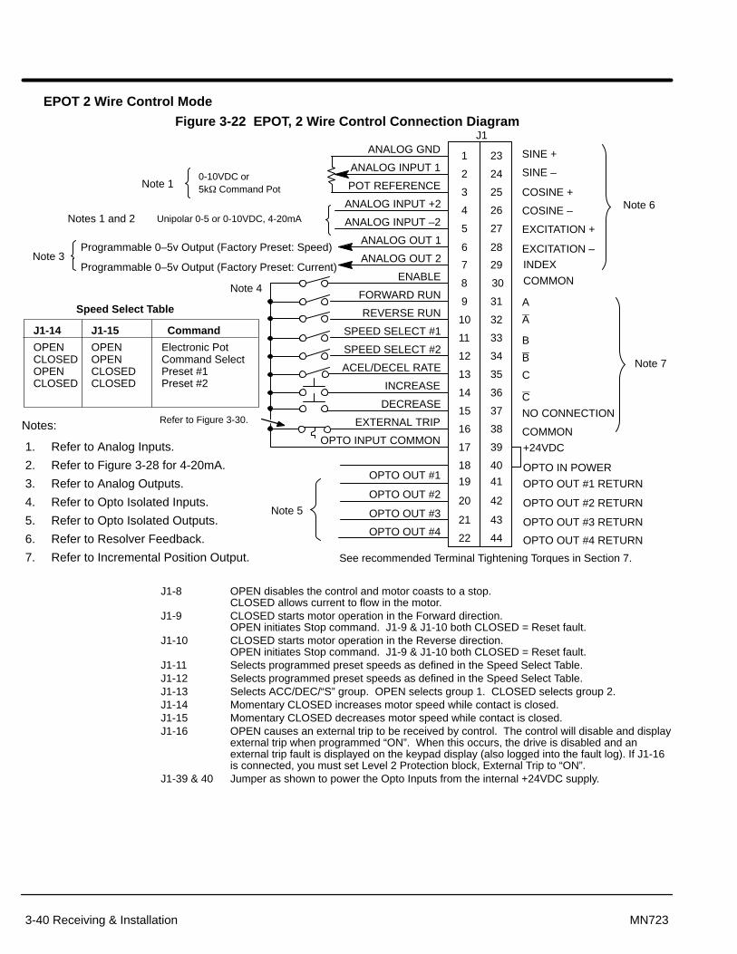
Section 1General Information
3-40 Receiving & Installation MN723
EPOT 2 Wire Control Mode
Figure 3-22 EPOT, 2 Wire Control Connection Diagram
INCREASE
8
9
10
11
12
13
14
15
16
17
18
19
20
21
22
ENABLE
FORWARD RUN
REVERSE RUN
SPEED SELECT #1
SPEED SELECT #2
ACEL/DECEL RATE
EXTERNAL TRIP
OPTO INPUT COMMON
Programmable 0–5v Output (Factory Preset: Speed)
J1ANALOG GND
ANALOG INPUT 1
POT REFERENCE
ANALOG INPUT +2
ANALOG INPUT –2
ANALOG OUT 1
ANALOG OUT 2
OPTO OUT #1
OPTO OUT #2
OPTO OUT #3
OPTO OUT #4
1
2
3
4
5
6
7Programmable 0–5v Output (Factory Preset: Current)
See recommended Terminal Tightening Torques in Section 7.
30
31
32
33
34
35
36
37
38
39
40
41
42
43
44
23
24
25
26
27
28
29
+24VDC
OPTO IN POWER
OPTO OUT #1 RETURN
OPTO OUT #2 RETURN
OPTO OUT #3 RETURN
OPTO OUT #4 RETURN
DECREASE
Note 3
Notes 1 and 2
Note 5
0-10VDC or5k� Command PotNote 1
Unipolar 0-5 or 0-10VDC, 4-20mA
Notes:
1. Refer to Analog Inputs.
2. Refer to Figure 3-28 for 4-20mA.
3. Refer to Analog Outputs.
4. Refer to Opto Isolated Inputs.
5. Refer to Opto Isolated Outputs.
6. Refer to Resolver Feedback.
7. Refer to Incremental Position Output.
SINE +
SINE –
COSINE +
COSINE –
EXCITATION +
EXCITATION –
A
A
B
B
C
C
NO CONNECTION
COMMON
Note 6
Note 7
J1-14 J1-15 Command
Electronic PotCommand SelectPreset #1Preset #2
Speed Select Table
OPENOPENCLOSEDCLOSED
OPENCLOSEDOPENCLOSED
Note 4
Refer to Figure 3-30.
INDEX
COMMON
J1-8 OPEN disables the control and motor coasts to a stop. CLOSED allows current to flow in the motor.
J1-9 CLOSED starts motor operation in the Forward direction. OPEN initiates Stop command. J1-9 & J1-10 both CLOSED = Reset fault.
J1-10 CLOSED starts motor operation in the Reverse direction. OPEN initiates Stop command. J1-9 & J1-10 both CLOSED = Reset fault.
J1-11 Selects programmed preset speeds as defined in the Speed Select Table.J1-12 Selects programmed preset speeds as defined in the Speed Select Table.J1-13 Selects ACC/DEC/“S” group. OPEN selects group 1. CLOSED selects group 2.J1-14 Momentary CLOSED increases motor speed while contact is closed.J1-15 Momentary CLOSED decreases motor speed while contact is closed.J1-16 OPEN causes an external trip to be received by control. The control will disable and display
external trip when programmed “ON”. When this occurs, the drive is disabled and anexternal trip fault is displayed on the keypad display (also logged into the fault log). If J1-16is connected, you must set Level 2 Protection block, External Trip to “ON”.
J1-39 & 40 Jumper as shown to power the Opto Inputs from the internal +24VDC supply.

Receiving & Installation 3-41MN723
EPOT 3 Wire Control Mode
Figure 3-23 EPOT, 3 Wire Control Connection Diagram
8
9
10
11
12
13
14
15
16
17
18
19
20
21
22
ENABLE
FORWARD RUN
REVERSE RUN
EXTERNAL TRIP
OPTO INPUT COMMON
Programmable 0–5v Output (Factory Preset: Speed)
J1ANALOG GND
ANALOG INPUT 1
POT REFERENCE
ANALOG INPUT +2
ANALOG INPUT –2
ANALOG OUT 1
ANALOG OUT 2
OPTO OUT #1
OPTO OUT #2
OPTO OUT #3
OPTO OUT #4
1
2
3
4
5
6
7Programmable 0–5v Output (Factory Preset: Current)
See recommended Terminal Tightening Torques in Section 7.
30
31
32
33
34
35
36
37
38
39
40
41
42
43
44
23
24
25
26
27
28
29
+24VDC
OPTO IN POWER
OPTO OUT #1 RETURN
OPTO OUT #2 RETURN
OPTO OUT #3 RETURN
OPTO OUT #4 RETURN
Note 3
Notes 1 and 2
Note 5
0-10VDC or5k� Command PotNote 1
Unipolar 0-5 or 0-10VDC, 4-20mA
Notes:
1. Refer to Analog Inputs.
2. Refer to Figure 3-28 for 4-20mA.
3. Refer to Analog Outputs.
4. Refer to Opto Isolated Inputs.
5. Refer to Opto Isolated Outputs.
6. Refer to Resolver Feedback.
7. Refer to Incremental Position Output.
Note 4
SINE +
SINE –
COSINE +
COSINE –
EXCITATION +
EXCITATION –
A
A
B
B
C
C
NO CONNECTION
COMMON
Note 6
Note 7
STOP
EPOT/Command Select
INCREASE
ACEL/DECEL RATE
DECREASERefer to Figure 3-30.
INDEX
COMMON
J1-8 OPEN disables the control and motor coasts to a stop. CLOSED allows current to flow in the motor.
J1-9 Momentary CLOSED starts motor operation in the Forward direction. J1-9 & J1-10 both CLOSED = Reset fault.
J1-10 Momentary CLOSED starts motor operation in the Reverse direction. J1-9 & J1-10 both CLOSED = Reset fault.
J1-11 Momentary OPEN, motor decels to a stop.J1-12 OPEN selects EPOT.
CLOSED selects Level 1 Command Select parameter value.J1-13 Selects ACC/DEC/“S” group. OPEN selects group 1. CLOSED selects group 2.J1-14 Momentary CLOSED increases motor speed while contact is closed.J1-15 Momentary CLOSED decreases motor speed while contact is closed.J1-16 OPEN causes an external trip to be received by control. The control will disable and display
external trip when programmed “ON”. When this occurs, the drive is disabled and anexternal trip fault is displayed on the keypad display (also logged into the fault log). If J1-16is connected, you must set Level 2 Protection block, External Trip to “ON”.
J1-39 & 40 Jumper as shown to power the Opto Inputs from the internal +24VDC supply.
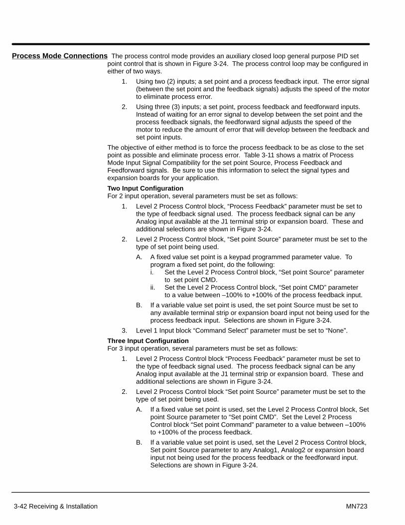
Section 1General Information
3-42 Receiving & Installation MN723
Process Mode Connections The process control mode provides an auxiliary closed loop general purpose PID setpoint control that is shown in Figure 3-24. The process control loop may be configured ineither of two ways.
1. Using two (2) inputs; a set point and a process feedback input. The error signal(between the set point and the feedback signals) adjusts the speed of the motorto eliminate process error.
2. Using three (3) inputs; a set point, process feedback and feedforward inputs.Instead of waiting for an error signal to develop between the set point and theprocess feedback signals, the feedforward signal adjusts the speed of themotor to reduce the amount of error that will develop between the feedback andset point inputs.
The objective of either method is to force the process feedback to be as close to the setpoint as possible and eliminate process error. Table 3-11 shows a matrix of ProcessMode Input Signal Compatibility for the set point Source, Process Feedback andFeedforward signals. Be sure to use this information to select the signal types andexpansion boards for your application.
Two Input ConfigurationFor 2 input operation, several parameters must be set as follows:
1. Level 2 Process Control block, “Process Feedback” parameter must be set tothe type of feedback signal used. The process feedback signal can be anyAnalog input available at the J1 terminal strip or expansion board. These andadditional selections are shown in Figure 3-24.
2. Level 2 Process Control block, “Set point Source” parameter must be set to thetype of set point being used.
A. A fixed value set point is a keypad programmed parameter value. Toprogram a fixed set point, do the following:i. Set the Level 2 Process Control block, “Set point Source” parameter
to set point CMD.ii. Set the Level 2 Process Control block, “Set point CMD” parameter
to a value between –100% to +100% of the process feedback input.
B. If a variable value set point is used, the set point Source must be set toany available terminal strip or expansion board input not being used for theprocess feedback input. Selections are shown in Figure 3-24.
3. Level 1 Input block “Command Select” parameter must be set to “None”.
Three Input ConfigurationFor 3 input operation, several parameters must be set as follows:
1. Level 2 Process Control block “Process Feedback” parameter must be set tothe type of feedback signal used. The process feedback signal can be anyAnalog input available at the J1 terminal strip or expansion board. These andadditional selections are shown in Figure 3-24.
2. Level 2 Process Control block “Set point Source” parameter must be set to thetype of set point being used.
A. If a fixed value set point is used, set the Level 2 Process Control block, Setpoint Source parameter to “Set point CMD”. Set the Level 2 ProcessControl block “Set point Command” parameter to a value between –100%to +100% of the process feedback.
B. If a variable value set point is used, set the Level 2 Process Control block,Set point Source parameter to any Analog1, Analog2 or expansion boardinput not being used for the process feedback or the feedforward input.Selections are shown in Figure 3-24.

Section 1General Information
Receiving & Installation 3-43MN723
3. Level 1 Input block “Command Select” parameter must be set to thefeedforward signal type. This signal may be any Analog1, Analog2 orexpansion board input not being used for the process feedback or Set pointSource inputs. Selections are shown in Figure 3-24.
Note: An input can only be used only one time: for Process Feedback, OR Set pointSource, OR Feedforward.
Figure 3-24 Simplified Process Control Block Diagram
COMMAND SELECTAvailable sources are:Potentiometer± 10 Volts± 5 Volts4-20 mA10 V w/Torq FFEXB Pulse Follower 5V EXB10 Volt EXB4-20mA EXB3-15 PSI EXBTachometer EXBSerialNone
∑∑
∑ ∑
PROCESS FEEDBACKAvailable sources are:Potentiometer± 10 Volts± 5 Volts4-20 mA 5V EXB10 Volt EXB4-20mA EXB3-15 PSI EXBTachometer EXBNone
Closed to Enable Process Input (J1–13)
ACC/DECS–CurveProfiler
Differentiator
EXB PulseFollower Only
ss
Proportional
Gp
Gp
Proportional
Differential
Differential
Amp
Gd s
Gd s
Integral
IntegralMotor
Gis
Gis
Set Point adjustment limit w/ integral clamp to maxlimit value
Existing Baldor Control System
Differentiator
–
–
+
+
+
+
PROCESS FEEDBACK
PROCESS FEEDFORWARD
Motor Control
Auxiliary PID Control
Baldor Series “H” ControlSET POINT SOURCEAvailable sources are:Set Point CommandPotentiometer± 10 Volts± 5 Volts 4-20 mA5V EXB10 Volt EXB4-20mA EXB3-15 PSI EXBTachometer EXBNone
SET POINT SOURCE
+
+
+
+
+
+
Resol.

Section 1General Information
3-44 Receiving & Installation MN723
Table 3-11 Process Mode Input Signal Compatibility
Set point orFeedback
Set po int orFeedforward J1-1 & 2 J1-4 & 5 5V EXB� 10V EXB�
4-20mAEXB�
3-15 PSIEXB�
DC Tach EXB�
J1-1 & 2J1-4 & 55V EXB� ËËËËË
ËËËËË10V EXB� ËËËËËËËËËË4-20mA EXB� ËËËËË
3-15 PSI EXB�ËËËËËËËË
ËËËËËËËËËË
ËËËËËËËËËËDC Tach EXB� ËËËËË
ËËËËËMPR/F EXB � � ËËËËËËËËËËSerial EXB � � ËËËË
ËËËËËËËËËËËËËË
ËËËËËËËËËË
ËËËËËËËËËË� Requires expansion board EXB007A02 (High Resolution Analog I/O EXB).
� Requires expansion board EXB004A01 (4 Output Relays/3-15 PSI Pneumatic Interface EXB).
� Requires expansion board EXB006A01 (DC Tachometer Interface EXB).
� Requires expansion board EXB005A01 (Master Pulse Reference/Isolated Pulse Follower EXB).
� Used for Feedforward only. Must not be used for Set point Source or Feedback.
� Requires expansion board EXB001A01 (RS232 Serial Communication EXB). or Requires expansion board EXB002A01 (RS422/RS485 Serial Communication EXB).
Requires expansion board EXB012A01 (RS232/RS485 Serial Communication EXB).
Conflicting inputs. Do not use same input signal multiple times.ËËËËËË Conflicting level 1 or 2 expansion boards. Do not use!
Process Mode Outputs
Analog Monitoring Outputs (Process Mode Only)
Name DescriptionProcess FDBK Process Feedback scaled input. Useful for observing or tuning the
process control loop.
Set point CMD Set point Command scaled input. Useful for observing or tuning theprocess control loop.
Speed Command Commanded Motor Speed. Useful for observing or tuning the output ofthe control loop.
Opto Isolated Outputs (Process Mode Only)
Name DescriptionProcess Error CLOSED when the Process Feedback is within the specified tolerance
band. OPEN when the Process Feedback is greater than the specifiedtolerance band. The width of the tolerance band is adjusted by theLevel 2 Process Control block Process ERR TOL parameter value.

Section 1General Information
Receiving & Installation 3-45MN723
Figure 3-25 Process Mode Connection Diagram
8
9
10
11
12
13
14
15
16
17
18
19
20
21
22
Enable
Forward Enable
Reverse Enable
Table Select
Process Mode Enable
External Trip
Opto Input Common
Programmable 0–5v Output (Factory Preset: Speed)
J1ANALOG GND
ANALOG INPUT 1
POT REFERENCE
ANALOG INPUT +2
ANALOG INPUT –2
ANALOG OUT 1
ANALOG OUT 2
OPTO OUT #1
OPTO OUT #2
OPTO OUT #3
OPTO OUT #4
1
2
3
4
5
6
7Programmable 0–5v Output (Factory Preset: Current)
See recommended Terminal Tightening Torques in Section 7.
30
31
32
33
34
35
36
37
38
39
40
41
42
43
44
23
24
25
26
27
28
29
+24VDC
OPTO IN POWER
OPTO OUT #1 RETURN
OPTO OUT #2 RETURN
OPTO OUT #3 RETURN
OPTO OUT #4 RETURN
Jog
Fault Reset
Note 3
Notes 1 and 2
Note 5
0-10VDC or5k� Command Pot
Note 1
Unipolar 0-5 or 0-10VDC, 4-20mA orDifferential ±5VDC, ±10VDC
Notes:
1. Refer to Analog Inputs.
2. Refer to Figure 3-28 for 4-20mA.
3. Refer to Analog Outputs.
4. Refer to Opto Isolated Inputs.
5. Refer to Opto Isolated Outputs.
6. Refer to Resolver Feedback.
7. Refer to Incremental Position Output.
Note 4No Connection
SINE +
SINE –
COSINE +
COSINE –
EXCITATION +
EXCITATION –
AA
B
B
C
C
NO CONNECTION
COMMON
Note 6
Note 7
Refer to Figure 3-30.
INDEX
COMMON
J1-8 CLOSED allows current to flow in the motor and produce torque.OPEN disables the control & motor coasts to a stop.
J1-9 CLOSED allows operation in the Forward direction. OPEN disables Forward operation (drive will brake to a stop if a Forward command isstill present). Reverse operation is still possible if J1-10 is closed. J1-9 & J1-10 both OPEN = brake to stop.
J1-10 CLOSED allows operation in the Reverse direction. OPEN disables Reverse operation (drive will brake to a stop if a Reverse command isstill present). Forward operation is still possible if J1-9 is closed. J1-9 & J1-10 both OPEN = brake to stop.
Note: A unipolar input signal will command one direction only.J1-11 OPEN = TABLE 0, CLOSED = TABLE 1.
J1-13 CLOSED to enable the Process Mode.
J1-14 CLOSED places control in JOG mode. The control will only JOG in the forwarddirection.
J1-15 CLOSED to reset a fault condition.OPEN to run.
J1-16 OPEN causes an external trip to be received by control. The control will disable anddisplay external trip when programmed “ON”. When this occurs, the drive is disabledand an external trip fault is displayed on the keypad display (also logged into the faultlog). If J1-16 is connected, you must set Level 2 Protection block, External Trip to “ON”.
J1-39 & Jumper as shown to power the Opto Inputs from the internal +24VDC supply.40

Section 1General Information
3-46 Receiving & Installation MN723
Analog Inputs and OutputsAnalog Inputs Two analog inputs are available: analog input #1 (J1-1 and J1-2) and analog input #2
(J1-4 and J1-5) as shown in Figure 3-26. Either analog input #1 or #2 may be groundedprovided the common mode range is not exceeded. Either analog input may be selectedin the Level 1 INPUT block, Command Select parameter value. Analog input #1 isselected if parameter value “Potentiometer” is selected. Analog input #2 is selected ifparameter value “+/–10Volts, +/–5 Volts or 4-20mA” is selected. Figure 3-27 shows theequivalent circuits of the Analog Inputs.
Figure 3-26 Analog Inputs and Outputs
Analog Ground
Analog Input 1
Pot Reference
Analog Input +2
Analog Input -2
Analog Output 1
Analog Output 2
Command Pot or
0-10VDC
Differential ±5VDC, ±10VDCor 4-20 mA Input
5K�
Programmable 0-5VDC (Factory Preset: Speed)
Programmable 0-5VDC (Factory Preset: Current)
See recommended Terminal Tightening Torques in Section 7.
Analog Input #1 The single ended analog input #1 can be used when the controller is set to Standard 3(Single Ended) Wire, 3SPD ANA 2 or 3 Wire, Process, or Bipolar Control (not Keypad or 15 Speed 2
Wire modes).
Analog input #1 can be used in one of three ways. Speed command (Level 1 Input block,Command Select=Potentiometer). Process Feedback (Level 2 Process Control block,Process Feedback=Potentiometer). Set point Source (Level 2 Process Control block, Setpoint Source=Potentiometer).
When using Analog Input #1, the respective parameter must be set to“POTENTIOMETER”.
Note: A potentiometer value of 5k� to 10k�, 0.5 watt may be used.
1. Connect the wires from the 5K� pot at the J1 terminal strip. One end of the potis connected to J1-1 (analog ground) and the other end is connected to J1-3(reference voltage).
2. Connect the wiper of the pot to J1-2. The voltage across terminals J1-1 andJ1-2 is the speed command input.
Note: A 0-10VDC speed command signal may be connected across J1-1 and J1-2instead of a 5K� pot.

Section 1General Information
Receiving & Installation 3-47MN723
Analog Input #2 Analog input #2 accepts a differential command ±5VDC, ±10VDC or 4-20 mA. The(Differential) operating mode is defined in the Level 1 Input block OPERATING MODE parameter.
Note: Analog Input #2 is used with Standard Run 3-Wire, 3SPD ANA 2 or 3 Wire orBipolar Control modes and not used for the Keypad or 15 Speed 2 Wire or theSerial operating modes.
1. Connect the Analog Input +2 wire to J1-4 and the –2 wire to J1-5.
2. If using a 4-20 mA command signal, jumper JP1 located on the main controlboard must be on pins 2 & 3. For all other modes, JP1 must be on pins 1 & 2.
Note: Analog Input #2 can be connected for single ended operation by groundingeither of the inputs, provided the common mode voltage range is notexceeded. The common mode voltage can be measured with a voltmeter.Apply the maximum command voltage to analog input 2 (J1-4, 5). Measurethe AC and DC voltage across J1-1 to J1-4. Add the AC and DC readingstogether. Measure the AC and DC voltage from J1-1 to J1-5. Add the AC andDC readings together.
If either of these measurement totals exceeds a total of ±15 volts, then thecommon mode voltage range has been exceeded. If the common modevoltage range has been exceeded, the solution is either to change thecommand voltage source or isolate the command voltage with a commerciallyavailable signal isolator.

Section 1General Information
3-48 Receiving & Installation MN723
Figure 3-27 Analog Inputs Equivalent Circuits
500W
+
–
.033 �f
5K�
1.96K�+15VDC
20K�
10K� 10K�
JP14-20mA +
–
X N/C
To Microprocessor
10K� 10K�
To Microprocessor
Notes:
+
–All OP Amps are TL082 or TL084
Analog Ground is separated from Chassis Ground. Electrically theyare separated by an RC network.
30K�-15VDCJ1
2
3
4
5
1
See recommended Terminal Tightening Torques in Section 7.
Figure 3-28 Series 23H Control
JP2
JP1
Refer to Table 3-12for jumper placement information.
1 2 3
12
3
Resolver Feedback Module 12
3
(on mian control board)
(on mian control board)
JP1 (on bottom side of resolverfeedback module)
1-22-3
Internal indexExternal Index
Table 3-12 Control Board Jumpers
Jumper Jumper Position Description of Jumper Position SettingJP1 1–2 Voltage Speed Command Signal. (Factory Setting)
2–3 4-20mA input at Analog #2
JP2 1–2 Factory Setting
2–3 Not used.
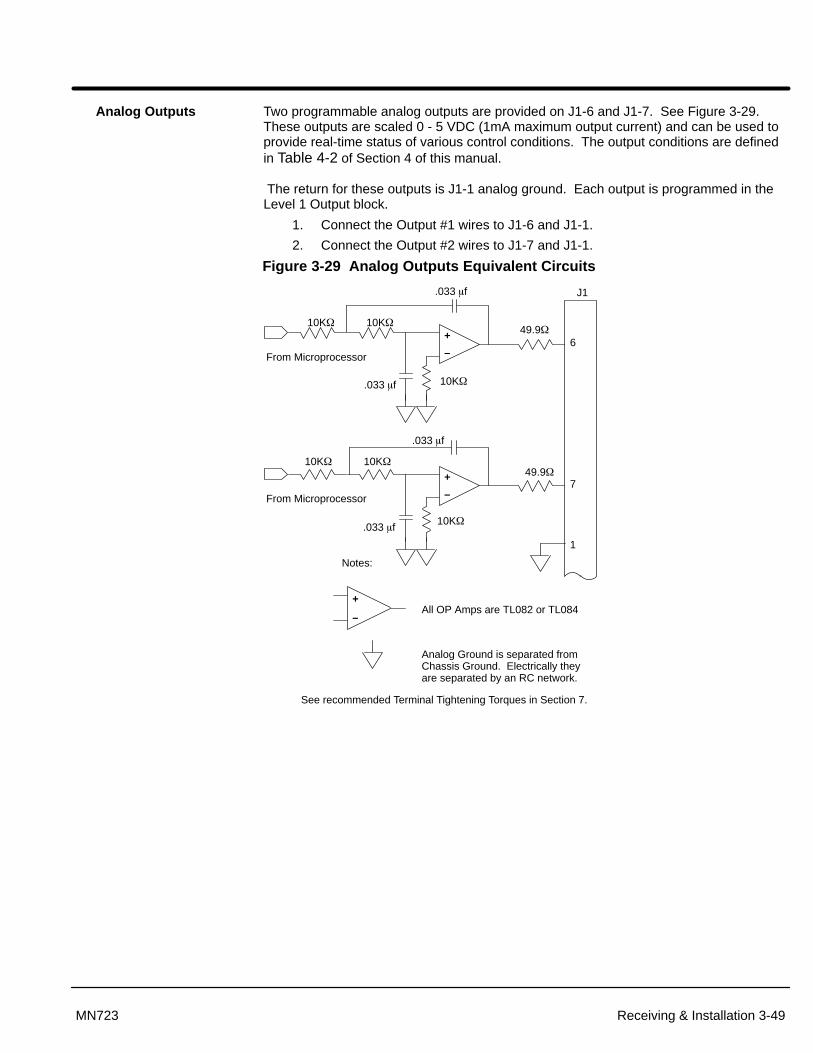
Section 1General Information
Receiving & Installation 3-49MN723
Analog Outputs Two programmable analog outputs are provided on J1-6 and J1-7. See Figure 3-29.These outputs are scaled 0 - 5 VDC (1mA maximum output current) and can be used toprovide real-time status of various control conditions. The output conditions are definedin Table 4-2 of Section 4 of this manual.
The return for these outputs is J1-1 analog ground. Each output is programmed in theLevel 1 Output block.
1. Connect the Output #1 wires to J1-6 and J1-1.
2. Connect the Output #2 wires to J1-7 and J1-1.
Figure 3-29 Analog Outputs Equivalent Circuits
+
–
10K�
10K�
.033 �f
10K�49.9�
.033 �f
6From Microprocessor
+
–
10K�
10K�
.033 �f
10K�49.9�
.033 �f
7From Microprocessor
Notes:
+
–All OP Amps are TL082 or TL084
Analog Ground is separated from Chassis Ground. Electrically theyare separated by an RC network.
1
See recommended Terminal Tightening Torques in Section 7.
J1

Section 1General Information
3-50 Receiving & Installation MN723
External Trip Input Terminal J1-16 is available for connection to a normally closed thermostat or overloadrelay in all operating modes as shown in Figure 3-30. The thermostat or overload relayshould be a dry contact type with no power available from the contact. If the motorthermostat or overload relay activates the control will automatically shut down and givean External Trip fault.
Connect the External Trip Input wires to J1-16 and J1-17. Do not place these wires in thesame conduit as the motor power leads.
To activate the External Trip input, the External Trip parameter in the programmingProtection Block must be set to “ON”.
Figure 3-30 Motor Temperature Relay
T1 T2 T3
T1
T2 T3G
* Motor
M M M
1617
J1
External Trip
External or remote motoroverload protection may be required by NationalElectrical Code or equivalent
Do not run these wires insame conduit as motorleads or AC power wiring.
Customer ProvidedSource Voltage
Motor Thermostat Leads
CR1*
* Optional hardware. Must be ordered separately.
Note: Add appropriately ratedprotective device for AC relay(snubber) or DC relay (diode).
See recommended Terminal Tightening Torques in Section 7.
Opto-Isolated Inputs The equivalent circuit for the nine Opto inputs is shown in Figure 3-31. The function ofeach input depends on the operating mode selected. Refer to the operating modeconnection diagrams shown previously in this section.
Figure 3-31 Opto-Input Equivalent Circuit (Using Internal Supply)
9
10
11
12
13
14
15
16
Opto Input 2
Opto Input 3
Opto Input 4
Opto Input 5
Opto Input 6
Opto Input 7
J1
See recommended Terminal Tightening Torques in Section 7.
Opto Input 8
Opto Input 9
39
40
+24VDC @ 200mA (supply terminal 39).
Jumper terminals 39 to 40(Factory Installed)
6.8K 6.8K 6.8K 6.8K 6.8K 6.8K 6.8K 6.8K
17Opto Input Common
8Opto Input 1
6.8K

Section 1General Information
Receiving & Installation 3-51MN723
Figure 3-32 Opto-Input Equivalent Circuit (Using External Supply)
9
10
11
12
13
14
15
16
Opto Input 2
Opto Input 3
Opto Input 4
Opto Input 5
Opto Input 6
Opto Input 7
J1
Opto Input 8
Opto Input 9
39
40
17
8Opto Input 1
* User VCC = 10 - 30VDCExternal Power Source
* User VCC (–)
* User VCC (+)
9
10
11
12
13
14
15
16
Opto Input 2
Opto Input 3
Opto Input 4
Opto Input 5
Opto Input 6
Opto Input 7
J1
Opto Input 8
Opto Input 9
39
40
17
8Opto Input 1
* User VCC (+)
* User VCC (–)
Opto Inputs Closing to Ground Opto Inputs Closing to +VCC
See recommended Terminal Tightening Torques in Section 7.

Section 1General Information
3-52 Receiving & Installation MN723
Opto-Isolated Outputs Four programmable Opto-isolated outputs are available at terminals J1-19 through J1-22.See Figure 3-33. Each output may be programmed to represent one output condition.The output conditions are defined in Table 4-2 of Section 4 of this manual.
The Opto-isolated outputs may be configured for sinking or sourcing 50 mA each.However, all must be configured the same. The maximum voltage from opto output tocommon when active is 1.0 VDC (TTL compatible). The Opto-isolated outputs may beconnected in different ways as shown in Figure 3-33. The equivalent circuit for theOpto-isolated outputs is shown in Figure 3-34.
If the opto outputs are used to directly drive a relay, a flyback diode rated at 1A, 100 V(IN4002) minimum should be connected across the relay coil. See Electrical NoiseConsiderations in Section 5 of this manual.
1. Connect OPTO OUT #1 wires to J1-19 and J1-41.
2. Connect OPTO OUT #2 wires to J1-20 and J1-42.
3. Connect OPTO OUT #3 wires to J1-21 and J1-43.
4. Connect OPTO OUT #4 wires to J1-22 and J1-44.
Each Opto Output is programmed in the Output programming block.
Figure 3-33 Opto-isolated Output Configurations
18
19
20
21
22
40
39
41
42
43
44
Using Internal Supply(Sinking the Relay Current)
18
19
20
21
22
40
39
41
42
43
44
OptionalCustomerSuppliedRelays
OptionalCustomerSuppliedRelays
Using Internal Supply(Sourcing the Relay Current)
18
19
20
21
22
40
39
41
42
43
44
Using External Supply(Sinking the Relay Current)
18
19
20
21
22
40
39
41
42
43
44
OptionalCustomerSuppliedRelays
OptionalCustomerSuppliedRelays
Using External Supply(Sourcing the Relay Current)
Optional Customer Supplied10VDC to 30VDC Source
Optional Customer Supplied10VDC to 30VDC Source
+24VDC24COM
+24VDC
+24VDC
+24VDC+
–
+
–
17
24COM 17 24COM 17
1724COM
See recommended Terminal Tightening Torques in Section 7.

Section 1General Information
Receiving & Installation 3-53MN723
Figure 3-34 Opto-Output Equivalent Circuit
19
20
21
22
41
42
43
Opto Output 1
Opto Output 2
Opto Output 3
Opto Output 4
Opto Out 1 Return
J1
See recommended Terminal Tightening Torques in Section 7.
Opto Out 2 Return
Opto Out 3 Return
44 Opto Out 4 Return
18
PC86550mA max
10 – 30VDCOpto Outputs
PC86550mA max
PC86550mA max
PC86550mA max
Pre-Operation Checklist Check of Electrical Items
CAUTION: After completing the installation but before you apply power, besure to check the following items.
1. Verify AC line voltage at source matches control rating.
2. Inspect all power connections for accuracy, workmanship and torque as well ascompliance to codes.
3. Verify control and motor are grounded to each other and the control isconnected to earth ground.
4. Check all signal wiring for accuracy.
5. Be certain all brake coils, contactors and relay coils have noise suppression.This should be an R-C filter for AC coils and reverse polarity diodes for DCcoils. MOV type transient suppression is not adequate.
WARNING: Make sure that unexpected operation of the motor shaft during startup will not cause injury to personnel or damage to equipment.
Check of Motors and Couplings
1. Verify freedom of motion of the motor shaft.
2. Verify that all motor couplings are tight without backlash.
3. Verify the holding brakes if any, are properly adjusted to fully release and set tothe desired torque value.

Section 1General Information
3-54 Receiving & Installation MN723
Power-Up Procedure Be sure the 23H control, motor and dynamic brake hardware are installed and wiredaccording to the procedures in Section 3 of this manual. Become familiar with the keypad programming and keypad operation of the control asdescribed in Section 4 of this manual.
1. Disconnect the load (including coupling or inertia wheels) from the motor shaft,if possible.
2. Verify that any enable inputs to J1-8 are open. Be sure Level 2 Protectionblock, Local Enable INP is OFF and Level 2 Protection block, External Trip isOFF.
3. Turn power on. Be sure no errors are displayed.
4. Set the Level 1 Input block, Operating Mode parameter to “KEYPAD”.
5. Set the Level 2 Output Limits block, “OPERATING ZONE” parameter as desired(STD CONST TQ, STD VAR TQ, QUIET CONST TQ or QUIET VAR TQ).
6. Enter the following motor data in the Level 2 Motor Data block parameters:Motor Rated Amps (IC)Motor PolesResolver Speeds (Pre-set is one speed)
7. If external dynamic brake hardware is used, set the Level 2 Brake Adjust block“Resistor Ohms”, “Resistor Watts” and “DC Brake Current” parameters.
8. If the load was not disconnected in step 1, refer to Section 6 and manually tunethe control. After manual tuning, perform steps 11 and 12 then continue withstep 16.
9. At the Level 2 Motor Data block, press ENTER, at CALC PRESETS select YES(using the key) and let the control calculate preset values for the parametersthat are necessary for control operation.
WARNING: The motor shaft will rotate during the autotune procedure. Becertain that unexpected motor shaft movement will not cause injuryto personnel or damage to equipment.
10. Go to Level 2 Autotune block, and perform the following tests:CMD OFFSET TRIMCUR LOOP COMPRESOLVER ALIGN
11. Set the Level 2 Output Limits block, “MIN OUTPUT SPEED” parameter.
12. Set the Level 2 Output Limits block, “MAX OUTPUT SPEED” parameter.
13. Remove all power from the control.
14. Couple the motor to its load.
15. Turn power on. Be sure no errors are displayed.
16. Perform the SPD CNTRLR CALC test in the Level 2 Autotune block.
17. Run the drive from the keypad using the arrow keys for direct speed control, akeypad entered speed or the JOG mode.
18. Select and program additional parameters to suit your application.
The control is now ready for use the in keypad mode. If a different operating mode isdesired, refer to Section 3 Control Connections and Section 4 Programming andOperation.

Section 4Programming and Operation
Programming & Operation 4-1MN723
Overview The keypad is used to program the control parameters, to operate the motor and tomonitor the status and outputs of the control by accessing the display options, thediagnostic menus and the fault log.
Figure 4-1 Keypad JOG - (Green) lights when Jog is active.FWD - (Green) lights when FWD direction is commanded.REV - (Green) lights when REV direction is commanded.STOP - (Red) lights when motor STOP is commanded.Indicator Lights
Keypad Display - Displays statusinformation during Local or Remoteoperation. It also displays informationduring parameter setup and fault orDiagnostic Information.
JOG - Press JOG to select thepreprogrammed jog speed. After the jogkey has been pressed, use the FWD orREV keys to run the motor in thedirection that is needed. The JOG key isonly active in the local mode.
FWD - Press FWD to initiate forwardrotation of the motor.
REV - Press REV to initiate reverserotation of the motor.
STOP - Press STOP one time to initiatea stop sequence. Depending on theKeypad Stop Mode, the motor will eitherREGEN or COAST to a stop. This key isoperational in all modes of operationunless disabled by the Keypad Stopparameter in the Keypad (programming)Setup Block. Press STOP twice todisable control (coast to stop).
LOCAL - Press LOCAL to changebetween the local (keypad) and remoteoperation. When the control is in thelocal mode all other external commandsto the J1 terminal strip will be ignoredwith the exception of the external tripinput.
DISP - Press DISP to return to displaymode from programming mode. Providesoperational status and advances to thenext display menu item including theDiagnostic Screens.
SHIFT - Press SHIFT in the programmode to control cursor movement.Pressing the SHIFT key once moves theblinking cursor one character position tothe right. While in program mode, aparameter value may be reset to thefactory preset value by pressing theSHIFT key until the arrow symbols at thefar left of the keypad display are flashing,then press an arrow key. In the displaymode the SHIFT key is used to adjustthe keypad contrast.
RESET - Press RESET to clear all faultmessages (in local mode). Can also beused to return to the top of the blockprogramming menu without saving anyparameter value changes.
PROG - Press PROG to enter theprogram mode. While in the programmode the PROG key is used to edit aparameter setting.
� - (UP Arrow). Press � to change the value of theparameter being displayed. Pressing �increments the value to the next greatervalue. Also, when the fault log orparameter list is displayed, the � key willscroll upward through the list. In thelocal mode pressing the � key willincrease motor speed to the next greatervalue.
� - (Down Arrow)Press � to change the value of theparameter being displayed. Pressing �decrements the value to the next lesservalue. Also, when the fault log orparameter list is displayed, the � key willscroll downward through the list. In thelocal mode pressing the � key willdecrease motor speed to the next lowervalue.
ENTER - Press ENTER to saveparameter value changes and moveback to the previous level in theprogramming menu. In the display modethe ENTER key is used to directly set thelocal speed reference. It is also used toselect other operations when promptedby the keypad display.

Section 1General Information
4-2 Programming & Operation MN723
Display Mode The control is in the DISPLAY MODE at all times except when parameter values arechanged (Programming mode). The Keypad Display shows the status of the control as inthe following example.
Motor StatusControl Operation
Output ConditionValue and Units
The DISPLAY MODE is used to view operating status, Diagnostic INFO, the Fault Logand to adjust the Display contrast. The description of how to do these tasks aredescribed on the following pages.
Adjusting Display Contrast When AC power is applied to the control, the keypad should display the status of thecontrol. If there is no visible display, use the following procedure to adjust the contrast ofthe display. Contrast may be adjusted in display mode when motor is stopped or running.
Action Description Display Comments
Apply Power No visible display
Press DISP Key Places control in display mode
Press SHIFT SHIFT Allows display contrastadjustment
Press � or � Key Adjusts display intensity
Press ENTER Saves level of contrast and exitsto display mode
Typical display
Display Mode Screens
Action Description Display Comments
Apply Power Logo display for 5 seconds.
Display mode showing motorspeed.
No faults present. Local keypadmode. If in remote/serial mode,press local for this display.
Press DISP key Display Frequency First Display Mode Screen.
Press DISP key Display Current
Press DISP key Display Voltage
Press DISP key Combined Display
Press DISP key Screen to enter Fault Log
Press DISP key Screen to enter Diagnostic Menu

Section 1General Information
Programming & Operation 4-3MN723
Display Mode Continued
Diagnostic Information Access
Action Description Display Comments
Press DISP key Scroll to Diagnostic Informationscreen
Diagnostic Access screen.
Press ENTER key Access diagnostic information. First Diagnostic Informationscreen.
Press DISP key Display mode showing controltemperature.
Press DISP key Display mode showing busvoltage. XXXV
Press DISP key Display mode showing %overload current remaining.
Press DISP key Display mode showing optoinputs & outputs states. (0=Open, 1=Closed.)
Opto Inputs states (Left); Opto Outputs states (Right).
Press DISP key Display mode showing actual timethe drive has been powered up.
HR.MIN.SEC format.
Press DISP key Display mode showing operatingzone, voltage and control type.
Typical display.
Press DISP key Display mode showing continuousamps; PK amps rating; amps/voltscale of feedback, power base ID.
Press DISP key Display mode showing whichGroup1 or 2 expansion boardsare installed and recognized.
In this case, no expansion boardsare installed.
Press DISP key Display mode showing positioncounter contents.
Press DISP key Display mode showing parametertable selected.
Press DISP key Display mode showing softwareversion and revision installed inthe control.
Press DISP key Displays exit choice. Press ENTER to exit diagnosticinformation.
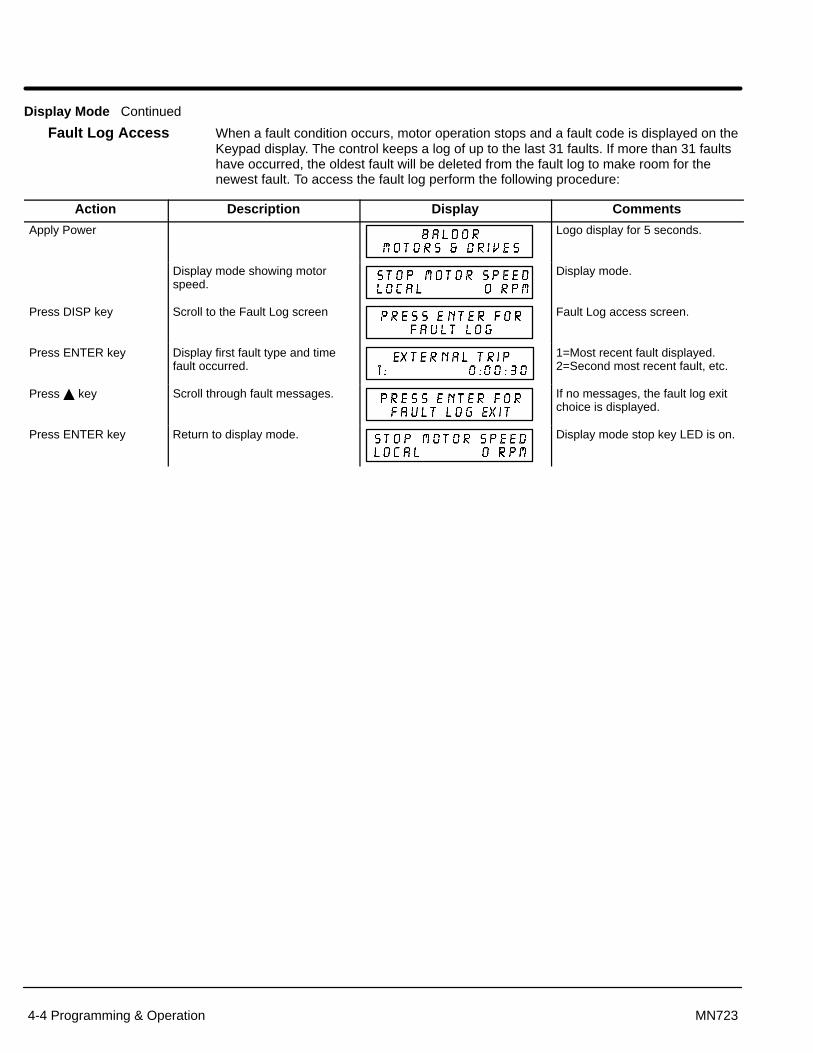
Section 1General Information
4-4 Programming & Operation MN723
Display Mode Continued
Fault Log Access When a fault condition occurs, motor operation stops and a fault code is displayed on theKeypad display. The control keeps a log of up to the last 31 faults. If more than 31 faultshave occurred, the oldest fault will be deleted from the fault log to make room for thenewest fault. To access the fault log perform the following procedure:
Action Description Display Comments
Apply Power Logo display for 5 seconds.
Display mode showing motorspeed.
Display mode.
Press DISP key Scroll to the Fault Log screen Fault Log access screen.
Press ENTER key Display first fault type and timefault occurred.
1=Most recent fault displayed.2=Second most recent fault, etc.
Press � key Scroll through fault messages. If no messages, the fault log exitchoice is displayed.
Press ENTER key Return to display mode. Display mode stop key LED is on.
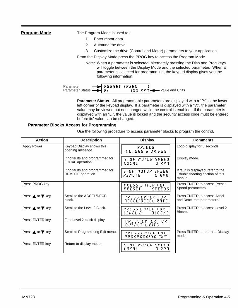
Section 1General Information
Programming & Operation 4-5MN723
Program Mode The Program Mode is used to:
1. Enter motor data.
2. Autotune the drive.
3. Customize the drive (Control and Motor) parameters to your application.
From the Display Mode press the PROG key to access the Program Mode.
Note: When a parameter is selected, alternately pressing the Disp and Prog keyswill toggle between the Display Mode and the selected parameter. When aparameter is selected for programming, the keypad display gives you thefollowing information:
Parameter StatusParameter
Value and Units
Parameter Status . All programmable parameters are displayed with a “P:” in the lowerleft corner of the keypad display. If a parameter is displayed with a “V:”, the parametervalue may be viewed but not changed while the control is enabled. If the parameter isdisplayed with an “L:”, the value is locked and the security access code must be enteredbefore its’ value can be changed.
Parameter Blocks Access for ProgrammingUse the following procedure to access parameter blocks to program the control.
Action Description Display Comments
Apply Power Keypad Display shows thisopening message.
Logo display for 5 seconds.
If no faults and programmed forLOCAL operation.
Display mode.
If no faults and programmed forREMOTE operation.
If fault is displayed, refer to theTroubleshooting section of thismanual.
Press PROG key Press ENTER to access PresetSpeed parameters.
Press � or � key Scroll to the ACCEL/DECELblock.
Press ENTER to access Acceland Decel rate parameters.
Press � or � key Scroll to the Level 2 Block. Press ENTER to access Level 2Blocks.
Press ENTER key First Level 2 block display.
Press � or � key Scroll to Programming Exit menu. Press ENTER to return to Displaymode.
Press ENTER key Return to display mode.
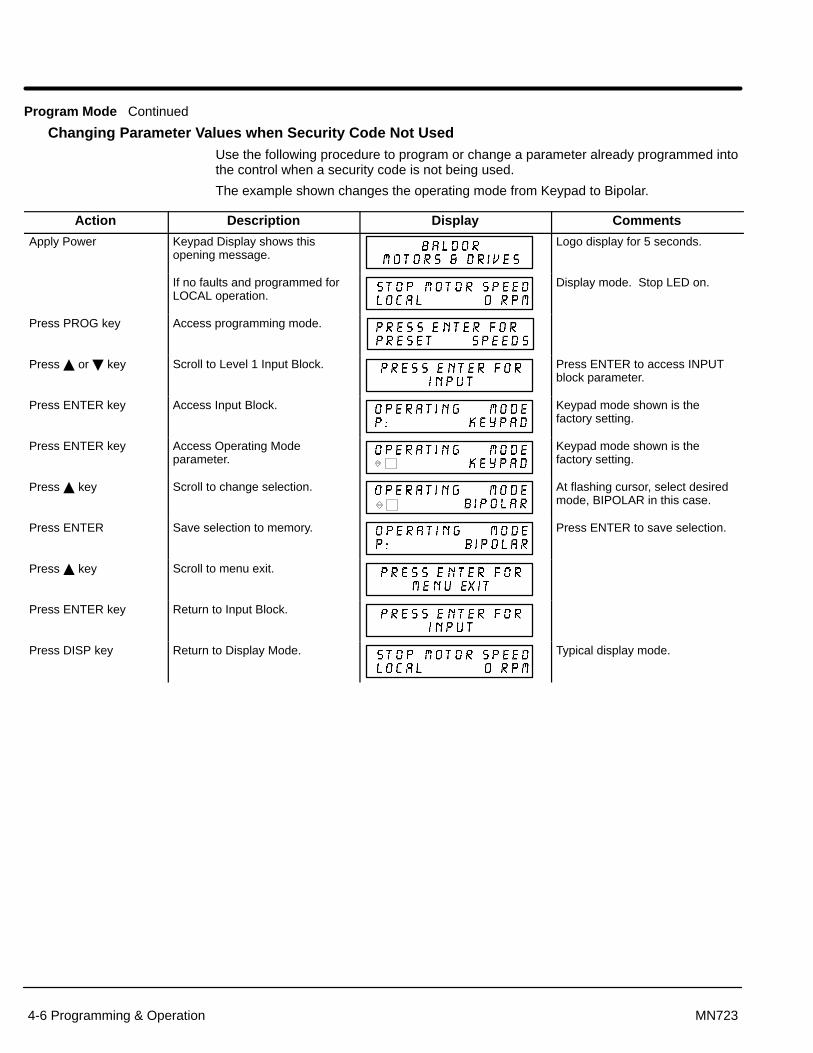
Section 1General Information
4-6 Programming & Operation MN723
Program Mode Continued
Changing Parameter Values when Security Code Not Used Use the following procedure to program or change a parameter already programmed intothe control when a security code is not being used.
The example shown changes the operating mode from Keypad to Bipolar.
Action Description Display Comments
Apply Power Keypad Display shows thisopening message.
Logo display for 5 seconds.
If no faults and programmed forLOCAL operation.
Display mode. Stop LED on.
Press PROG key Access programming mode.
Press � or � key Scroll to Level 1 Input Block. Press ENTER to access INPUTblock parameter.
Press ENTER key Access Input Block. Keypad mode shown is thefactory setting.
Press ENTER key Access Operating Modeparameter.
Keypad mode shown is thefactory setting.
Press � key Scroll to change selection. At flashing cursor, select desiredmode, BIPOLAR in this case.
Press ENTER Save selection to memory. Press ENTER to save selection.
Press � key Scroll to menu exit.
Press ENTER key Return to Input Block.
Press DISP key Return to Display Mode. Typical display mode.

Section 1General Information
Programming & Operation 4-7MN723
Program Mode Continued
Reset Parameters to Factory SettingsSometimes it is necessary to restore the parameter values to the factory settings. Followthis procedure to do so. Be sure to change the Level 2 Motor Data block “Motor RatedAmps” to the correct value after this procedure (restored factory setting is 999).
Note: All parameter values are changed when the control is reset to factory settings.
Note: After factory settings have been restored, the drive must again be tuned.
Action Description Display Comments
Apply Power Keypad Display shows thisopening message.
Logo display for 5 seconds.
If no faults and programmed forLOCAL operation.
Display mode. Stop LED on.
Press PROG key Enter program mode.
Press � or � key Scroll to Level 2 Blocks.
Press ENTER key Select Level 2 Blocks.
Press � or � key Scroll to the Miscellaneous block.
Press ENTER key Select Miscellaneous block.
Press � key Scroll to Factory Settingsparameter.
Press ENTER key Access Factory Settingsparameter.
� represents blinking cursor.
Press � key Scroll to YES, to choose originalfactory settings.
Press ENTER key Restores factory settings. “Loading Presets” is first message“Operation Done” is next“No” is displayed last.
Press � key Scroll to menu exit. Exit Level 2 blocks.
Press ENTER key Return to Level 1 blocks. Exit Level 2 blocks.
Press � or � key Scroll to Programming exit. Exit Programming mode andreturn to Display mode.
Press ENTER key Return to display mode. Display mode. Stop LED on.

Section 1General Information
4-8 Programming & Operation MN723
Program Mode Continued
Initialize New SoftwareWhen new software is installed, the control must be initialized to the new software versionand memory locations. Use the following procedure to initialize the software.
Note: All parameter values are changed when the control is reset to factory settings.
Note: After factory settings have been restored, the drive must again be tuned.
Action Description Display Comments
Apply Power Keypad Display shows thisopening message.
Logo display for 5 seconds.
If no faults and programmed forLOCAL operation.
Display mode. Stop LED on.
Press PROG key Enter program mode.
Press � or � key Scroll to Level 2 Blocks.
Press ENTER key Select Level 2 Blocks.
Press � or � key Scroll to the Miscellaneous block.
Press ENTER key Select Miscellaneous block.
Press � key Scroll to Factory Settingsparameter.
Press ENTER key Access Factory Settingsparameter.
� represents blinking cursor.
Press � key Scroll to YES, to choose originalfactory settings.
Press ENTER key Restores factory settings. “Loading Presets” is first message“Operation Done” is next“No” is displayed last.
Press � key Scroll to menu exit.
Press ENTER key Return to display mode. Display mode. Stop LED on.
Press � key Scroll to diagnostic info block.
Press ENTER key Access diagnostic information. Displays commanded speed,direction of rotation, Local/Remote and motor speed.
Press DISP key Display mode showing softwareversion and revision installed inthe control.
XXX-X.XX
Verify new software version.
Press DISP key Displays exit choice. Press ENTER to exit diagnosticinformation.

Section 1General Information
Programming & Operation 4-9MN723
Parameter Definitions To make programming easier, parameters have been arranged into the two levelstructure shown in Table 4-1. Press the PROG key to enter the programming mode andthe “Preset Speeds” programming block will be displayed. Use the Up (�) and Down(�) arrows to scroll through the parameter blocks. Press ENTER to access parameterswithin a programming block.
Tables 4-2 and 4-3 provide an explanation of each parameter. A complete ParameterBlock Values list is located at the end of this manual. This list defines the programmablerange and factory preset value for each parameter. The list has a space to record yoursettings for future reference.
Table 4-1 List of Parameters
LEVEL 1 BLOCKS LEVEL 2 BLOCKS Preset Speeds Input Output Limits Brake AdjustPreset Speed #1 Operating Mode Operating Zone Resistor OhmsPreset Speed #2 Command Select Min Output Speed Resistor WattsPreset Speed #3 ANA CMD Inverse Max Output SpeedPreset Speed #4 ANA CMD Offset PK Current Limit Process ControlPreset Speed #5 ANA 2 Deadband PWM Frequency Process FeedbackPreset Speed #6 ANA1 CUR Limit CUR Rate Limit Process InversePreset Speed #7 Setpoint Source
Preset Speed #8 Output Custom Units Setpoint CommandPreset Speed #9 Opto Output #1 Decimal Places Set PT ADJ LimitPreset Speed #10 Opto Output #2 Value at Speed Process ERR TOLPreset Speed #11 Opto Output #3 Units of Measure Process PROP GainPreset Speed #12 Opto Output #4 Process INT GainPreset Speed #13 Zero SPD Set PT Protection Process DIFF GainPreset Speed #14 At Speed Band Overload Follow I:O RatioPreset Speed #15 Set Speed External Trip Follow I:O OUT
Analog Out #1 Local Enable INP Master EncoderAccel / Decel Rate Analog Out #2 Following ErrorAccel Time #1 Analog #1 Scale CommunicationsDecel Time #1 Analog #2 Scale Miscellaneous ProtocolS-Curve #1 Position Band Restart Auto/Man Baud RateAccel Time #2 Restart Fault/Hr Drive AddressDecel Time #2 Brushless Control Restart DelayS-Curve #2 Feedback Align Factory Settings Auto-Tuning
Speed Filter Homing Speed CALC PresetsJog Settings Feedback Align Homing Offset CMD Offset TrimJog Speed Current PROP Gain CUR Loop CompJog Accel Time Current INT Gain Security Control Feedback AlignJog Decel Time Speed PROP Gain Security State SPD CNTRLR CalcJog S-Curve Time Speed INT Gain Access Timeout
Speed DIFF Gain Access CodeKeypad Setup Position GainKeypad Stop Key Motor DataKeypad Stop Mode Motor Rated AmpsKeypad Run Fwd Motor PolesKeypad Run Rev Resolver SpeedsKeypad Jog Fwd CALC PresetsKeypad Jog RevLocal Hot Start
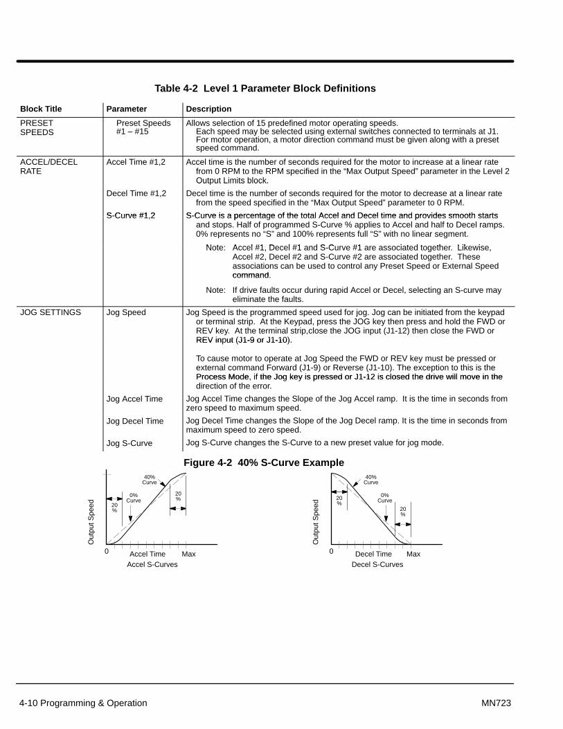
Section 1General Information
4-10 Programming & Operation MN723
Table 4-2 Level 1 Parameter Block Definitions
Block Title Parameter Description
PRESETSPEEDS
Preset Speeds#1 – #15
Allows selection of 15 predefined motor operating speeds. Each speed may be selected using external switches connected to terminals at J1.For motor operation, a motor direction command must be given along with a presetspeed command.
ACCEL/DECELRATE
Accel Time #1,2 Accel time is the number of seconds required for the motor to increase at a linear ratefrom 0 RPM to the RPM specified in the “Max Output Speed” parameter in the Level 2Output Limits block.
Decel Time #1,2
S-Curve #1 2
Out ut Limits block.
Decel time is the number of seconds required for the motor to decrease at a linear ratefrom the speed specified in the “Max Output Speed” parameter to 0 RPM.
S-Curve is a percentage of the total Accel and Decel time and provides smooth startsS-Curve #1,2 S-Curve is a percentage of the total Accel and Decel time and provides smooth startsand stops. Half of programmed S-Curve % applies to Accel and half to Decel ramps.0% represents no “S” and 100% represents full “S” with no linear segment.
Note: Accel #1 Decel #1 and S Curve #1 are associated together LikewiseNote: Accel #1, Decel #1 and S-Curve #1 are associated together. Likewise,Accel #2, Decel #2 and S-Curve #2 are associated together. Theseassociations can be used to control any Preset Speed or External Speedcommandcommand.
Note: If drive faults occur during rapid Accel or Decel, selecting an S-curve mayeliminate the faults.
JOG SETTINGS Jog Speed Jog Speed is the programmed speed used for jog. Jog can be initiated from the keypador terminal strip. At the Keypad, press the JOG key then press and hold the FWD orREV key. At the terminal strip,close the JOG input (J1-12) then close the FWD orREV input (J1-9 or J1-10).REV in ut (J1-9 or J1-10).
To cause motor to operate at Jog Speed the FWD or REV key must be pressed orexternal command Forward (J1-9) or Reverse (J1-10). The exception to this is theProcess Mode, if the Jog key is pressed or J1-12 is closed the drive will move in the
Jog Accel Time
Process Mode, if the Jog key is pressed or J1-12 is closed the drive will move in thedirection of the error.
Jog Accel Time changes the Slope of the Jog Accel ramp. It is the time in seconds fromzero speed to maximum speed.
Jog Decel Time
Jog S-Curve
Jog Decel Time changes the Slope of the Jog Decel ramp. It is the time in seconds frommaximum speed to zero speed.
Jog S-Curve changes the S-Curve to a new preset value for jog mode.
Figure 4-2 40% S-Curve Example
Out
put S
peed
Accel Time0 MaxAccel S-Curves
20%
20%
0%Curve
40%Curve
Out
put S
peed
Decel Time0 MaxDecel S-Curves
20%
20%
0%Curve
40%Curve

Section 1General Information
Programming & Operation 4-11MN723
Table 4-2 Level 1 Parameter Block Definitions - Continued
Block Title Parameter Description
KEYPAD SETUP Keypad Stop Key
Keypad Stop Mode
Stop Key - Allows keypad STOP key to initiate motor stop during remote or serialoperation (if Stop key is set to Remote ON in Standard Run, 15 Speed,Bipolar, Serial and Process Control modes). If active, pressing STOP au-tomatically selects Local mode and initiates the stop command.
Stop Mode - Selects if the Stop command causes the motor to COAST to a stop orREGEN to a stop. In COAST, the motor is turned off and allowed to coastto a stop. In REGEN, the voltage and frequency to the motor is reduced ata rate set by Decel Time
Keypad Run FWD
Keypad Run REV
Keypad Jog FWD
Keypad Jog REV
Loc. Hot Start
a rate set by Decel Time.
Run FWD - ON makes the keypad FWD key active in Local mode.
Run REV - ON makes the keypad REV key active in Local mode.
Jog FWD - ON makes the keypad FWD key active in Local Jog mode.
Jog REV - ON makes the keypad REV key active in Local Jog mode.
Loc. Hot Start - The STOP input at J4-11 in the Keypad mode is enabled (when ON).
INPUT Operating Mode
Command Select
Ten “Operating Modes” are available. Choices are: Keypad, Standard Run, 15SPD,Serial, Bipolar, Process, 3 SPD ANA 2 wire, 3 SPD ANA 3 wire, EPOT - 2 Wire andEPOT - 3 Wire. External connections to the control are made at the J1 terminal strip(wiring diagrams are shown in Section 3 “Control Circuit Connections”).
Selects the external speed reference to be used.
The easiest method of speed control is to select POTENTIOMETER and connect a 5K�pot to J1-1, J1-2, and J1-3.
±5, ±10VDC or 4-20mA input command can be applied to J1-4 and J1-5.
If long distance is required between the external speed control and the control, the 4-20mAselections at J1-4 and J1-5 should be considered. Current loop allows long cable lengthswithout attenuation of the command signal.
10 VOLT W/TORQ FF - when a differential command is present at J1-4 and 5, allows addi-tional 5V torque feedforward input at J1-1, 2 and 3 to set a predetermined amount oftorque inside the rate loop with high gain settings.
EXB PULSE FOL - selects optional Master Pulse Reference/Isolated Pulse Follower ex-pansion board if installed.
5VOLT EXB - selects optional High Resolution I/O expansion board if installed.
10VOLT EXB - selects optional High Resolution I/O expansion board if installed.
4-20mA EXB - selects optional High Resolution I/O expansion board if installed.
3-15 PSI EXB selects optional 3-15 PSI expansion board if installed.
Tachometer EXB- selects optional DC Tachometer expansion board if installed.
Serial -selects optional Serial Communications expansion board if installed.
None - Used in Process Control mode, two input configuration with no Feedforward input.
Note: When using the 4-20mA input, the JP2 jumper on the main control boardmust be moved to the left two pins “A”.
ANA CMD Inverse “OFF” will cause a low input voltage (e.g. 0VDC) to be a low motor speed command anda maximum input voltage (e.g. 10VDC) to be a maximum motor speed command.
“ON” will cause a low input voltage (e.g. 0VDC) to be a maximum motor speed commandand a maximum input voltage (e.g. 10VDC) to be a low motor speed command.
ANA CMD Offset Provides an offset to the Analog Input to minimize signal drift. For example, if theminimum speed signal is 1VDC (instead of 0VDC) the ANA CMD Offset can be set to-10% so the minimum voltage input is seen by control as 0VDC. The value of thisparameter is automatically adjusted during Autotune “CMD Offset Trim” test.
ANA 2 Deadband Allows a defined range of voltage to be a deadband. A command signal within thisrange will not affect the control output. The deadband value is the voltage above andbelow the zero command signal level.
ANA 1 CUR Limit Allows the 5V input at J1-2 (referenced to J1-1) to be used for reduction of theprogrammed current limit parameter for torque trimming during operation.

Section 1General Information
4-12 Programming & Operation MN723
Table 4-2 Level 1 Parameter Block Definitions - Continued
Block Title Parameter Description
OUTPUT OPTO OUTPUT #1 – #4
Four optically isolated digital outputs that have two operating states, logical High or Low.Each output may be configured to any of the following conditions:
Condition Description
Ready - Active when power is applied and no faults are present.
Zero Speed - Active when motor RPM is below the value of the Level 1 Output“Zero SPD Set Pt” parameter.
At Speed - Active when output speed is within the speed range defined bythe Level 1 Output “At Speed Band” parameter.
Overload - Active during an Overload fault caused by a time out whenoutput current is greater than Rated Current.
Keypad Control - Active when control is in Local keypad control.
At Set Speed - Active when output speed is at or above the Level 1 Output “Set Speed” parameter.
Fault - Active when a fault condition is present.
Following ERR - Active when the motor speed is outside the user specifiedtolerance band defined by the At Speed Band parameter.
Motor Direction - Active High when REV direction command received. Active Lowwhen FWD direction command received.
Drive On - Active when control is “Ready” (has reached excitation level andcapable of producing torque).
CMD Direction - Active at all times. Logical output state indicates Forward orReverse direction. High=FWD, Low=REV.
At Position - Active during a positioning command when control is within theposition band parameter tolerance.
Over Temp Warn - Active when control heat sink is within 3°C of Int Overtemp.
Process Error - Active when process feedback signal is outside the rangespecified by the Level 2 Process Control block, AT SetpointBand parameter. Turns off when process feedback error iseliminated.
Drive Run - Active when drive is Ready, Enabled, Speed or Torque commandreceived with FWD/REV direction issued.
Serial - Active when drive is in the Serial mode.
Zero SPD Set PT Sets the speed at which the Zero Speed opto output becomes active (turns on). When thespeed is less than the ZERO SPD SET PT, the Opto Output becomes active. This is use-ful when a motor brake is to interlock operation with a motor.
At Speed Band The At Speed Band serves two Opto Output Conditions and the Level 2 Protection blockFollowing Error:
Sets the speed range in RPM at which the At Speed opto output turns on and remainsactive within the range.
Sets the Following Error Tolerance Band for the Level 1 OUTPUT, Opto Output conditionFollowing ERR. The opto output is active if the motor speed is outside this band.
Sets the no fault operating speed range of the drive. This value is used by the Level 2Protection block, Following Error parameter (if it is set to ON). If the drive speed fallsout of this band, the Level 2 Protection block, Following Error parameter will shutdown the drive (if it is set to ON).
Set Speed Sets the speed that the At Set Speed opto output becomes active (turns on). When thespeed is greater than the Level 1 Output SET SPEED parameter, the Opto Outputbecomes active. This is useful when another machine must not start or stop until themotor exceeds a predetermined speed.
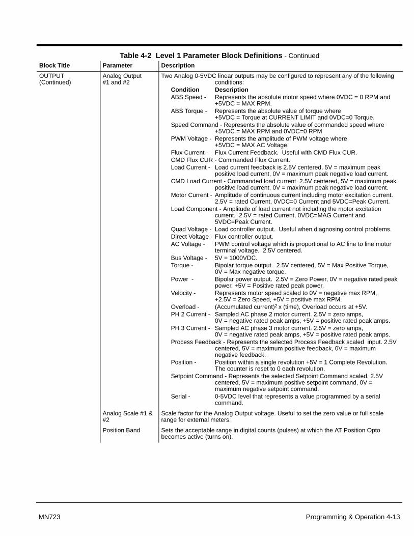
Section 1General Information
Programming & Operation 4-13MN723
Table 4-2 Level 1 Parameter Block Definitions - ContinuedBlock Title Parameter Description
OUTPUT(Continued)
Analog Output #1 and #2
Two Analog 0-5VDC linear outputs may be configured to represent any of the followingconditions:
Condition DescriptionABS Speed - Represents the absolute motor speed where 0VDC = 0 RPM and
+5VDC = MAX RPM.ABS Torque - Represents the absolute value of torque where
+5VDC = Torque at CURRENT LIMIT and 0VDC=0 Torque.Speed Command - Represents the absolute value of commanded speed where
+5VDC = MAX RPM and 0VDC=0 RPMPWM Voltage - Represents the amplitude of PWM voltage where
+5VDC = MAX AC Voltage.Flux Current - Flux Current Feedback. Useful with CMD Flux CUR.CMD Flux CUR - Commanded Flux Current.Load Current - Load current feedback is 2.5V centered, 5V = maximum peak
positive load current, 0V = maximum peak negative load current.CMD Load Current - Commanded load current 2.5V centered, 5V = maximum peak
positive load current, 0V = maximum peak negative load current.Motor Current - Amplitude of continuous current including motor excitation current.
2.5V = rated Current, 0VDC=0 Current and 5VDC=Peak Current.Load Component - Amplitude of load current not including the motor excitation
current. 2.5V = rated Current, 0VDC=MAG Current and5VDC=Peak Current.
Quad Voltage - Load controller output. Useful when diagnosing control problems.Direct Voltage - Flux controller output.AC Voltage - PWM control voltage which is proportional to AC line to line motor
terminal voltage. 2.5V centered.Bus Voltage - 5V = 1000VDC.Torque - Bipolar torque output. 2.5V centered, 5V = Max Positive Torque,
0V = Max negative torque.Power - Bipolar power output. 2.5V = Zero Power, 0V = negative rated peak
power, +5V = Positive rated peak power.Velocity - Represents motor speed scaled to 0V = negative max RPM,
+2.5V = Zero Speed, +5V = positive max RPM.Overload - (Accumulated current)2 x (time), Overload occurs at +5V.PH 2 Current - Sampled AC phase 2 motor current. 2.5V = zero amps,
0V = negative rated peak amps, +5V = positive rated peak amps.PH 3 Current - Sampled AC phase 3 motor current. 2.5V = zero amps,
0V = negative rated peak amps, +5V = positive rated peak amps.Process Feedback - Represents the selected Process Feedback scaled input. 2.5V
centered, 5V = maximum positive feedback, 0V = maximumnegative feedback.
Position - Position within a single revolution +5V = 1 Complete Revolution. The counter is reset to 0 each revolution.
Setpoint Command - Represents the selected Setpoint Command scaled. 2.5Vcentered, 5V = maximum positive setpoint command, 0V =maximum negative setpoint command.
Serial - 0-5VDC level that represents a value programmed by a serialcommand.
Analog Scale #1 
Scale factor for the Analog Output voltage. Useful to set the zero value or full scalerange for external meters.
Position Band Sets the acceptable range in digital counts (pulses) at which the AT Position Optobecomes active (turns on).
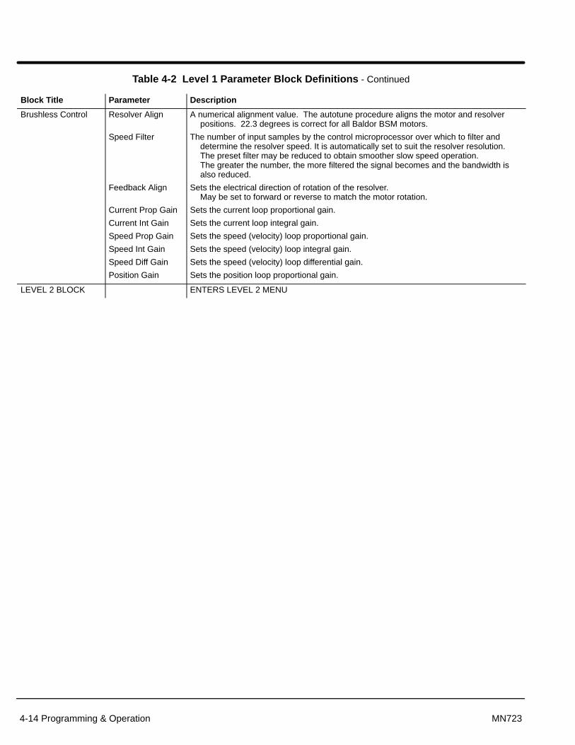
Section 1General Information
4-14 Programming & Operation MN723
Table 4-2 Level 1 Parameter Block Definitions - Continued
Block Title Parameter Description
Brushless Control Resolver Align
Speed Filter
Feedback Align
Current Prop Gain
Current Int Gain
Speed Prop Gain
Speed Int Gain
Speed Diff Gain
Position Gain
A numerical alignment value. The autotune procedure aligns the motor and resolverpositions. 22.3 degrees is correct for all Baldor BSM motors.
The number of input samples by the control microprocessor over which to filter anddetermine the resolver speed. It is automatically set to suit the resolver resolution.The preset filter may be reduced to obtain smoother slow speed operation. The greater the number, the more filtered the signal becomes and the bandwidth isalso reduced.
Sets the electrical direction of rotation of the resolver. May be set to forward or reverse to match the motor rotation.
Sets the current loop proportional gain.
Sets the current loop integral gain.
Sets the speed (velocity) loop proportional gain.
Sets the speed (velocity) loop integral gain.
Sets the speed (velocity) loop differential gain.
Sets the position loop proportional gain.
LEVEL 2 BLOCK ENTERS LEVEL 2 MENU

Section 1General Information
Programming & Operation 4-15MN723
Table 4-3 Level 2 Parameter Block Definitions
Block Title Parameter Description
OUTPUT LIMITS Operating Zone Sets the PWM operating zone to Standard 2.5KHz or Quiet 8.0KHz output carrierfrequency. Two output power modes are also selectable: Constant Torque andVariable Torque.
Constant Torque allows 170 - 200% for 3 seconds overload or 150% for 60 secondsoverload.
Variable Torque allows 115% peak overload for 60 seconds.
MIN Output Speed Sets the minimum motor speed in RPM. During operation, the motor speed will not beallowed to go below this value except for motor starts from 0 RPM or during dynamicbraking to a stop or in Process mode.
MAX Output Speed Sets the maximum motor speed in RPM.
PK Current Limit The maximum output peak current to the motor. Values above 100% of the rated currentare available depending upon the operating zone selected.
PWM Frequency The frequency that the output transistors are switched. PWM frequency is also referredto as “Carrier” frequency. PWM should be as low as possible to minimize stress onthe output transistors and motor windings. It is recommended that the PWMfrequency be set to approximately 16 times the maximum output frequency of thecontrol. Ratios less than 16 will result in non-Sinusoidal current waveforms. SeeFigure 4-3.
Current Rate Limit Limits the rate of torque change in response to a torque command.
Figure 4-3 Maximum Output Frequency vs PWM Frequency
50
100
200
300
400
500
600
700
800
900
1.00KHz 8.00KHz 16.00KHz
HZ
It is recommended that the PWM frequency parameter be setto approximately16 times the maximum output frequency ofthe control. The greater the ratio, the more sinusoidal theoutput current waveform will be.
OU
TP
UT
FR
EQ
UE
NC
Y
PWM FREQUENCY
Note: The output current rating of the control must be deratedfor operation between 8KHz and 16KHz PWM frequency.Derating is 10% from 2.5kHz to 5kHz and is linear from10% at 8KHz to a 30% reduction of rated output currentat 16KHz PWM operation.
1000

Section 1General Information
4-16 Programming & Operation MN723
Table 4-3 Level 2 Parameter Block Definitions Continued
Block Title Parameter Description
CUSTOM UNITS Max DecimalPlaces
Value At Speed
Value DEC Places
Value Speed REF
Units of Measure
Units of MEAS 2
The number of decimal places of the Output Rate display on the Keypad display. Thisvalue will be automatically reduced for large values. The output rate display is onlyavailable if the “Value At Speed” parameter value is non-zero.
Sets the desired output rate value per motor RPM. Two numbers are displayed on thekeypad display (separated by a slash “/”). The first number (left most) is the value youwant the keypad to display at a specific motor speed (second number, right most). Adecimal may be inserted into the numbers by placing the flashing cursor over theup/down arrow.
Serial Only. *
Serial Only. *
Allows you to specify units of measure to be displayed on the Output Rate display. Usethe shift and arrow keys to scroll to the first and successive characters. If thecharacter you want is not displayed, move the flashing cursor over the specialup/down character arrow on the left side of the display. Use the up/down arrows andthe shift key to scroll through all 9 character sets. Use the ENTER key to save yourselection.
Serial Only. *
PROTECTION Overload Sets the protection mode to Fault (trip off during overload condition) or to Foldback(automatically reduce the output current below the continuous output level) during anoverload. Foldback is the choice if continuous operation is desired. Fault will requirethe control be “Reset” manually or automatically after an overload.
External Trip OFF - External Trip is Disabled.ON - External Trip is enabled. If a normally closed contact at J1-16 is opened, anExternal Trip fault will occur and cause the drive to shut down.
Local Enable INP OFF - Ignores J1-8 switched input when in the “LOCAL” mode.ON - Requires J1-8 Enable input to be closed to enable the control when in the“LOCAL” mode.
Following Error This parameter determines if the control is to monitor the amount of following errorthat occurs in an application. Following Error is the programmable tolerance for theAT Speed Opto output as defined by the Level 1 Output block, AT Speed Bandparameter. Operation outside the speed range will cause a fault and the drive willshut down.
* Note: Serial Commands. When using the serial command option, the “Value AT Speed”, “Value DEC Places”, and “ValueSpeed REF” parameters must be set. The Value AT Speed parameter sets the desired output rate per increment ofmotor speed. The Value DEC Places sets the desired number of decimal places of the Value AT Speed number. TheValue Speed REF sets the increment of motor speed for the desired output rate.
The Units of Measure parameter sets the two left-most characters of the custom units display while the Units of MEAS2 parameter sets the two right most characters. For example, if “ABCD” is the custom units, “AB” is set in the Level 2Custom Units block, Units of Measure parameter and “CD” is set in the Level 2 Custom Units block, Units of MEAS 2parameter.
Note: Custom Display Units. The output rate display is only available if the Value AT Speed parameter has been changedfrom a value of 0 (zero). To access the Output Rate display, use the DISP key to scroll to the Output Rate display.

Section 1General Information
Programming & Operation 4-17MN723
Caution: If an automatic restart of the motor control could cause injury topersonnel, the automatic restart feature should be disabled bychanging the Level 2 Miscellaneous block, Restart Auto/Manparameter to manual.
Table 4-3 Level 2 Parameter Block Definitions Continued
Block Title Parameter Description
MISCELLANEOUS Restart Auto/Man Manual - If a fault or power loss occurs, the control must be manually reset to resumeoperation.Automatic - If a fault or power loss occurs, the control will automatically reset toresume operation.
Restart Fault/Hr The maximum number of automatic restart attempts before requiring a manual restart.After one hour without reaching the maximum number of faults or if power is turnedoff and on again, the fault count is rest to zero.
Restart Delay The amount of time allowed after a fault condition for an automatic restart to occur.Useful to allow sufficient time to clear a fault before restart is attempted.
Factory Settings Restores factory settings for all parameter values. Select YES and press “ENTER” keyto restore factory parameter values. The keypad Display will show “Operation Done”then return to “NO” when completed.
Note: When factory settings are reset, the Motor Rated Amps value is reset to999.9 amps. This Level 2 Motor Data block parameter value must bechanged to the correct value (located on the motor rating plate) beforeattempting to start the drive.
Homing Speed In Bipolar and Serial modes, this parameter sets the speed that the motor shaft willrotate to a “Home” position when the orient input switch is closed (J1-11).
Homing Offset In Bipolar and Serial modes, this parameter sets the number of digital encoder countspast home at which the motor stop command is issued. Quadrature encoder pulsesare 4 times the number of encoder lines per revolution. The recommended minimumnumber is 100 encoder counts to allow for deceleration distance to allow the motor tostop smoothly.
Note: Homing direction is always forward.
SECURITYCONTROL
Security State Off - No security Access Code required to change parameter values.Local - Requires security Access Code to be entered before changes can be made
using the Keypad.Serial - Requires security Access Code to be entered before changes can be made
using the Serial Link.Total - Requires security Access Code to be entered before changes can be made
using the Keypad or serial link.Note: If security is set to Local, Serial or Total you can press PROG and scroll
through the parameter values that are programmed but you are not allowedto change them unless you enter the correct access code.
Access Timeout The time in seconds the security access remains enabled after leaving the programmingmode. If you exit and go back into the program Mode within this time limit, thesecurity Access Code does not have to be re-entered. This timer starts when leavingthe Program Mode (by pressing DISP). Access Timeout is operational only in Localsecurity mode.
Note: This feature is not available when using the Serial operating mode or ifpower is cycled.
Access Code A 4 digit number code. Only persons that know the code can change secured Level 1and Level 2 parameter values. A loss of power to the control will automaticallyrequire the secured access code for parameter adjustments.
Note: Please record your access code and store it in a safe place. If you cannotgain entry into parameter values to change a protected parameter, pleasecontact Baldor. Be prepared to give the 5 digit code shown on the lowerright side of the Keypad Display at the Security Control Access Codeparameter prompt.

Section 1General Information
4-18 Programming & Operation MN723
Table 4-3 Level 2 Parameter Block Definitions Continued
Block Title Parameter Description
MOTOR DATA Motor Rated Amps The full load motor current (listed on the motor nameplate). If the motor current exceedsthis value for a period of time, an Overload fault will occur.
Motor Poles The number of motor poles. Factory setting is 4 poles. The values shown here are forstandard Baldor BSM motors.
NUMBER OFMOTOR POLESBSM63, BSM80 4BSM90, BSM100 8BSM4F, BSM6F, BSM8F 8BSM2R, BSM3R, BSM4R 4BSM6R 6
Resolver Speed The resolver speed. All standard BSM motors use 1 speed resolvers.
CALC Presets Loads operating values into memory. These values are based on informationprogrammed into the Level 2 Output Limits and Motor Data parameter values. CALC Presets must be run before Autotuning or manually tuning the drive.
BRAKE ADJUST Resistor Ohms The dynamic braking resistor value in ohms. Refer to dynamic braking manual or callBaldor for additional information.
Resistor Watts The dynamic braking resistor watts rating. Refer to dynamic braking manual or callBaldor for additional information.
PROCESSCONTROL
Process FeedbackProcess Inverse
Setpoint Source
Setpoint Command
Set PT ADJ Limit
Process ERR TOL
Process PROPGain
Process INT Gain
Process DIFF Gain
Sets the type of signal used for the process feedback signal.Causes the process feedback signal to be inverted. Used with reverse acting processes
that use a unipolar signal such as 4-20mA. If “ON”, 20mA will decrease motor speedand 4mA will increase motor speed.
Sets the source input signal to which the process feedback will be compared. If “Setpoint CMD” is selected, the fixed value of the set point is entered in the SetpointCommand parameter value.
Sets the value of the setpoint the control will try to maintain by adjusting motor speed.This is only used when the Setpoint Source is a fixed value “Setpoint CMD” underSetpoint Source.
Sets the maximum speed correction value to be applied to the motor (in response to themaximum feedback setpoint error). For example, if the max motor speed is 1750RPM, the setpoint feedback error is 100% and the setpoint adjustment limit is 10%,the maximum speed the motor will run in response to the setpoint feedback error is±175 RPM. If at the process setpoint, the motor speed is 1500 RPM, the maximumspeed adj limits is then 1325 to 1675 RPM.
Sets the width of the comparison band (% of setpoint) with which the process input iscompared. The result is that if the process input is within the comparison band thecorresponding Opto Output will become active.
Sets the PID loop proportional gain. This determines how much adjustment to motorspeed (within the Set PT ADJ Limit) is made to move the analog input to the setpoint.
Sets the PID loop Integral gain. This determines how quickly the motor speed isadjusted to correct long term error.
Sets the PID loop differential gain. This determines how much adjustment to motorspeed (within the Set PT ADJ Limit) is made for transient error.

Section 1General Information
Programming & Operation 4-19MN723
Table 4-3 Level 2 Parameter Block Definitions Continued
Block Title Parameter Description
PROCESSCONTROL(Continued)
Follow I:O Ratio
Follow I:O Out
Master Encoder
Sets the ratio of the Master to the Follower in Master/Follower configurations. Requiresthe Master Pulse Reference/ Isolated Pulse Follower expansion board. For example,the master encoder you want to follow is a 1024 count encoder. The follower motoryou wish to control also has a 1024 count encoder on it. If you wish the follower torun twice the speed of the master, a 1:2 ratio is entered. Fractional ratios such as0.5:1 are entered as 1:2. Ratio limits are 65,535:1 to 1:20.
Note: The Master Encoder parameter must be defined if a value is entered in theFollow I:O Ratio parameter.
Note: When using Serial Communications to operate the control, this value is theMASTER portion of the ratio. The FOLLOWER portion of the ratio is set inthe Follow I:O Out parameter.
This parameter is visible for use only when Serial Communication is used to operate thecontrol. A Master Pulse Reference/ Isolated Pulse Follower expansion board isrequired. This parameter represents the FOLLOWER portion of the ratio. The MASTER portion of the ratio is set in the Follow I:O Ratio parameter.
Only used if an optional Master Pulse Reference/Isolated Pulse Follower expansionboard is installed. Defines the number of pulses per revolution of the master encoder.Only used for follower drives.
COMMUNICATIONS Protocol Sets the type of communication the control is to use, RS-232 or RS-485 ASCII (text)protocol.
Baud Rate Sets the speed at which communication is to occur.
Drive Address Sets the address of the control for communication with other microprocessors.
AUTO TUNING
CALC Presets
CMD Offset TrimCUR Loop COMPResolver Align
SPD CNTRLRCALC
The Auto Tune procedure is used to automatically measure and calculate certainparameter values. Occasionally, the Auto Tune procedure cannot be run due tovarious circumstances such as the load cannot be uncoupled from the motor. Thecontrol can be manually tuned by entering the parameter values based oncalculations you have made. Refer to “Manually Tuning the Control” in theTroubleshooting section of this manual.
This procedure loads preset values into memory that are required to perform Auto Tune.Always run CALC Presets as the first step of Auto Tune.
This procedure trims offset voltage at the differential analog input at J1A-4 and J1A-5.Measures current response while running motor at one half the rated motor current.This procedure checks the electrical alignment of the resolver with respect to the motor
stator. This test locks the motor rotor into a reference position and proceeds to checkare re-adjust if necessary.
Should be performed with the load coupled to the motor shaft. Sets the motor current toacceleration ratio, Integral gain and Differential gain values. If done under no load,the Integral gain will be too large for high inertia loads if the PK Current Limit is set toolow. If the control is too responsive when the motor is loaded, adjust the PK CurrentLimit parameter to a greater value and repeat this test.
LEVEL 1 BLOCK ENTERS LEVEL 1 MENU

Section 1General Information
4-20 Programming & Operation MN723
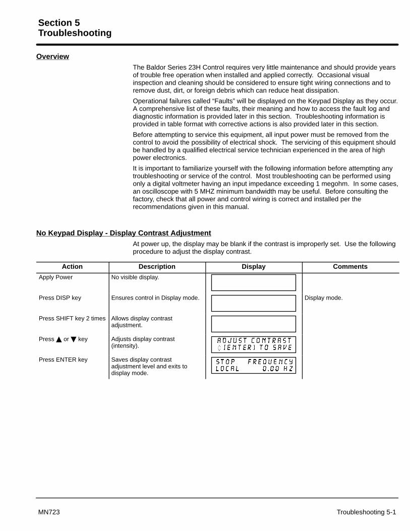
Section 5Troubleshooting
Troubleshooting 5-1MN723
OverviewThe Baldor Series 23H Control requires very little maintenance and should provide yearsof trouble free operation when installed and applied correctly. Occasional visualinspection and cleaning should be considered to ensure tight wiring connections and toremove dust, dirt, or foreign debris which can reduce heat dissipation.
Operational failures called “Faults” will be displayed on the Keypad Display as they occur.A comprehensive list of these faults, their meaning and how to access the fault log anddiagnostic information is provided later in this section. Troubleshooting information isprovided in table format with corrective actions is also provided later in this section.
Before attempting to service this equipment, all input power must be removed from thecontrol to avoid the possibility of electrical shock. The servicing of this equipment shouldbe handled by a qualified electrical service technician experienced in the area of highpower electronics.
It is important to familiarize yourself with the following information before attempting anytroubleshooting or service of the control. Most troubleshooting can be performed usingonly a digital voltmeter having an input impedance exceeding 1 megohm. In some cases,an oscilloscope with 5 MHZ minimum bandwidth may be useful. Before consulting thefactory, check that all power and control wiring is correct and installed per therecommendations given in this manual.
No Keypad Display - Display Contrast AdjustmentAt power up, the display may be blank if the contrast is improperly set. Use the followingprocedure to adjust the display contrast.
Action Description Display Comments
Apply Power No visible display.
Press DISP key Ensures control in Display mode. Display mode.
Press SHIFT key 2 times Allows display contrastadjustment.
Press � or � key Adjusts display contrast(intensity).
Press ENTER key Saves display contrastadjustment level and exits todisplay mode.

Section 1General Information
5-2 Troubleshooting MN723
How to Access Diagnostic Information
Action Description Display Comments
Apply Power Logo display for 5 seconds.
Display mode showing motorspeed.
No faults present. Local keypadmode. If in remote/serial mode,disable drive then press local forthis display.
Press DISP key 6 times Scroll to Diagnostic Informationscreen
Diagnostic Access screen.
Press ENTER key Access diagnostic information. First Diagnostic Informationscreen.
Press DISP key Display showing controltemperature.
Press DISP key Display showing bus voltage.
XXXV
Press DISP key Display showing % overloadcurrent remaining.
Press DISP key Display showing real time optoinput & output states. (0=Open, 1=Closed).
Opto Inputs states (Left); Opto Outputs states (Right).
Press DISP key Display showing actual driverunning time.
HR.MIN.SEC format.
Press DISP key Display showing operating zone,voltage and control type.
Press DISP key Display showing continuousamps; PK amps rating; amps/voltscale of feedback, power base ID.
ID is a hexadecimal value.
Press DISP key Display showing which Group1 or2 expansion boards are installedand recognized.
In this case, no expansion boardsare installed.
Press DISP key Display showing software versionand revision installed in thecontrol.
Press DISP key Displays exit choice. Press ENTER to exit diagnosticinformation.

Troubleshooting 5-3MN723
How to Access the Fault Log When a fault condition occurs, motor operation stops and a fault code is displayed onthe Keypad display. The control keeps a log of up to the last 31 faults. If more than 31faults have occurred, the oldest fault will be deleted from the fault log to make room forthe newest fault. To access the fault log use the following procedure:
Action Description Display Comments
Apply Power Logo display for 5 seconds.
Display mode showing outputfrequency
Display mode.
Press DISP key 5 times Use DISP key to scroll to theFault Log entry point.
Press ENTER key Display first fault type and timefault occurred.
Typical display.
Press � key Scroll through fault messages. If no messages, the fault log exitchoice is displayed.
Press ENTER key Return to display mode. Display mode stop key LED is on.
How to Clear the Fault Log Use the following procedure to clear the fault log and reset the internal clock.
Action Description Display Comments
Apply Power Logo display for 5 seconds.
Display mode showing outputfrequency.
Display mode.
Press DISP key Press DISP to scroll to the FaultLog entry point.
Press ENTER key Displays most recent message. 1 = most recent fault2 = second most recent fault, etc.
Press SHIFT key
Press RESET key
Press SHIFT key
Press ENTER key Fault log is cleared. No faults in fault log and theinternal clock is reset.
Press � or � key Scroll Fault Log Exit.
Press ENTER key Return to display mode.

5-4 Troubleshooting MN723
Table 5-1 Fault Messages
FAULT MESSAGE DESCRIPTION
Current Sens FLT Defective phase current sensor or open circuit detected between control board and currentsensor.
DC Bus High Bus over voltage condition occurred.
DC Bus Low Bus under voltage condition occurred.
External Trip An open circuit on J1-16 typically indicating an external over temperature conditionoccurred.
GND FLT Low impedance path detected between an output phase and ground.
INT Over-Temp Temperature of control heatsink exceeded safe level.
Invalid Base ID Control does not recognize power base ID.
Inverter Base ID Control board installed on power base without current feedback.
Line Regen FLT Only applies to Series 21H and 22H Line Regen controls.
Logic Supply FLT Logic power supply not working properly.
Lost User Data Battery backed RAM parameters have been lost or corrupted. When fault cleared (Reset), the control should reset to factory preset values.
Low INIT Bus V Insufficient bus voltage on startup.
Memory Error EEPROM error occurred. Contact Baldor.
New Base ID Control board sensed a different power base since last time it was powered up.
No Faults Fault log is empty.
No EXB Installed Programmed operating parameter requires an expansion board that is not installed or isnot recognized.
Over Current FLT Instantaneous over current condition detected by bus current sensor.
Overload - 1 min Output current exceeded 1 minute rating.
Overload - 3 sec Output current exceeded 3 second rating.
Over speed Motor RPM exceeded 110% of programmed MAX Motor Speed.
�P Reset Power cycled before the residual Bus voltage reached 0VDC.
PWR Base FLT Desaturation of power device occurred or bus current threshold exceeded.
Regen R PWR FLT Regen power exceeded DB resistor rating.
User Fault Text Custom software operating fault occurred.
Co–Processor Fault Co-Processor hardware fault occurred. Contact Baldor.

Section 1General Information
Troubleshooting 5-5MN723
Table 5-2 Troubleshooting
INDICATION POSSIBLE CAUSE CORRECTIVE ACTION
No Display Lack of input voltage. Check input power for proper voltage. Verify fuses are good (or breaker is not tripped).
Loose connections. Check input power termination.Verify connection of operator keypad.
Adjust display contrast. See Adjust Display Contrast in this section.
Current Sense FLT Open circuit between control boardand current sensor.
Check connections between control board and current sensor.
Defective current sensor. Replace current sensor.
DC Bus High Excessive dynamic braking power. Increase the DECEL time.Check dynamic brake watt and resistance parameter values.Add optional dynamic braking hardware.
Dynamic brake wiring problem. Check dynamic brake hardware wiring.
Input voltage too high.
Too fast a Decel rate.
Verify proper AC line voltage.Use step down isolation transformer if needed.Use line reactor to minimize spikes.Increase Decel time parameter value.
DC Bus Low Input voltage too low. Disconnect dynamic brake hardware and repeat operation.Verify proper AC line voltage.Use step up isolation transformer if needed.Check power line disturbances (sags caused by start up of
other equipment).Monitor power line fluctuations with date and time imprint
to isolate power problem.
External Trip Motor ventilation insufficient. Clean motor air intake and exhaust.Check external blower for operation.Verify motor’s internal fan is coupled securely.
Motor draws excessive current. Check motor for overloading. Verify proper sizing of control and motor.
No thermostat connected. Connect thermostat.Verify connection of all external trip circuits used with thermostat.Disable thermostat input at J1-16 (External Trip Input).
Poor thermostat connections. Check thermostat connections.
External trip parameter incorrect. Verify connection of external trip circuit at J1-16.
Set external trip parameter to “OFF” if no connection made at J1-16.
GND FLT Improper wiring.
Wiring shorted in conduit.Motor winding shorted.
Disconnect wiring between control and motor. Retry test. If GND FLT is cleared, reconnect motor leads and retry the test. Rewire as necessary.Repair motor.If GND FLT remains, contact Baldor.
INT Over-Temp Drive Overloaded. Correct motor loading.Verify proper sizing of control and motor.
Ambient temperature too high. Relocate control to cooler operating area.Add cooling fans or air conditioner to control cabinet.
Cooling fans clogged or restrictedair path.
Clean fans and air path.

Section 1General Information
5-6 Troubleshooting MN723
Table 5-2 Troubleshooting Continued
INDICATION POSSIBLE CAUSE CORRECTIVE ACTION
Invalid Base ID Control does not recognize HP andVoltage configuration.
Press “RESET” key on keypad. If fault remains, call Baldor.
Inverter Base ID Power base with no output phasecurrent sensors being used.
Replace power base with one that has output phase current feedback. Contact Baldor.
Logic Supply FLT Power supply malfunctioned. Replace logic power supply.
Lost User Data Battery backed memory failure. Parameter data was erased. Disconnect power to control and apply power (cycle power). Enter all parameters. Cycle power. If problem persists, contact Baldor.
Low INIT Bus V Improper AC line voltage. Disconnect Dynamic Brake hardware and retry test.Check input AC voltage level.
Memory Error EEPROM memory fault occurred. Press “RESET” key on keypad. If fault remains, call Baldor.
�P Reset Power was cycled before Busvoltage reached 0VDC.
Press “RESET” key on keypad. Disconnect power and allow at least 5 minutes for Bus capacitors todischarge before applying power. If fault remains, call Baldor.
Motor has wrongresponse toSpeed Command
Analog input common mode voltagemay be excessive.
Connect control input source common to control common to minimizecommon mode voltage. Maximum common mode voltage at terminalsJ1-4 and J1-5 is ±15VDC referenced to chassis common.
Motor Will NotStart
Not enough starting torque. Increase Current Limit setting.Start
Motor overloaded. Check for proper motor loading.Check couplings for binding.Verify proper sizing of control and motor.
Control not in local mode ofoperation.
Place control in local mode.
Motor may be commanded to runbelow minimum frequency setting.
Increase speed command or lower minimum frequency setting.
Incorrect Command Selectparameter.
Change Command Select parameter to match wiring at J1.
Incorrect speed command. Verify control is receiving proper command signal at J1.
Motor Will NotReach Maximum
Max Output Speed set too low. Adjust MAX Output Speed parameter value.Reach MaximumSpeed Motor overloaded. Check for mechanical overload. If unloaded motor shaft does not rotate
freely, check motor bearings.
Improper speed command. Verify control is set to proper operating mode to receive speed command.Verify control is receiving proper command signal at input terminals.Check velocity loop gains.
Speed potentiometer failure. Replace potentiometer.
Motor Will NotStop Rotation
MIN Output Speed parameter settoo high.
Adjust MIN Output Speed parameter value.
Improper speed command. Verify control is receiving proper command signal at input terminals.Verify control is set to receive speed command.
Speed potentiometer failure. Replace potentiometer.
Analog input common mode voltagemay be excessive.
Connect control input source common to control common to minimizecommon mode voltage. Maximum common mode voltage at terminalsJ1-4 and J1-5 is ±15VDC referenced to chassis common.
Analog offset trim set incorrectly. Adjust the Level 1 Input block, ANA CMD Offset parameter value to obtainzero speed with a zero value input command.

Section 1General Information
Troubleshooting 5-7MN723
Table 5-2 Troubleshooting Continued
INDICATION POSSIBLE CAUSE CORRECTIVE ACTION
New Base ID Software parameters are notinitialized on newly installed control board.
Press “RESET” key on keypad to clear the fault condition. Cycle power(turn power OFF then ON). Reset parameter values to factory settings.Access diagnostics and compare power base ID number to list in Table 5-3to ensure a match. Re-enter the Parameter Block Values you recorded inthe User Settings at the end of this manual. Autotune the control.
No EXB Installed Parameter incorrectly set. Change Level 1 Input block, Command Select parameter and Level 2Process Control block, Process Feedback and Setpoint Sourceparameters, to selections that do not require an expansion board.
Need expansion board. Install the correct expansion board for selected operating mode.
Incorrect software Revision Software does not support the revision level of the board installed. Updatesoftware.
Over Current FLT Current Limit parameter set lowerthan drive rating.
Increase PK Current Limit parameter in the Level 2 Output Limits block, not to exceed drive rating.
ACCEL/DECEL time too short. Increase ACCEL/DEC parameters in the Level 1 ACCEL/DECEL Rate block.
Electrical noise from external DCcoils.
Install reverse biased diodes across all external DC relay coils as shown inthe Opto Output circuit examples of this manual. See Electrical NoiseConsiderations in this Section.
Electrical noise from external ACcoils.
Install RC snubbers on all external AC coils. See Electrical NoiseConsiderations in this Section.
Excessive load. Reduce the motor load.Verify proper sizing of control and motor.
Excessive motor current. Verify motor leads are properly connected to control. (Motor is phasesensitive, refer to Section 3 for connection information).
Overload - 3 SecFLT
Peak output current exceeded 3second rating.
Check PK Current Limit parameter in the Level 2 Output Limits block.
Change Overload parameter In the Level 2 Protection block from Trip to Foldback.
Check motor for overloading.Increase ACCEL time.Reduce motor load.Verify proper sizing of control and motor.
Excessive motor current. Verify motor leads are properly connected to control. (Motor is phasesensitive, refer to Section 3 for connection information).
Overload - 1 MinFLT
Peak output current exceeded 1minute rating.
Verify Level 2 Motor Data is correct.Check PK Current Limit parameter in the Level 2
Output Limits block.Change Overload parameter In the Level 2 Protection block
from Trip to Foldback.Check motor for overloading.Increase ACCEL/DECEL times.Reduce motor load.Verify proper sizing of control and motor.
Excessive motor current. Verify motor leads are properly connected to control. (Motor is phasesensitive, refer to Section 3 for connection information).

Section 1General Information
5-8 Troubleshooting MN723
Table 5-2 Troubleshooting Continued
INDICATION POSSIBLE CAUSE CORRECTIVE ACTION
Power Module Power supply failure. Press “RESET” key on keypad. If fault remains, call Baldor.
PWR Base FLT Improper ground
Excessive current.
Be sure control has separate ground wire to earth ground. Panel grounding or conduit connection is not sufficient.Disconnect motor leads from control and retry test. If fault remains, callBaldor.
Electrical noise from external DCcoils.
Install reverse biased diodes across all external DC relay coils as shown inthe Opto Output circuit examples of this manual. See Electrical NoiseConsiderations in this Section.
Electrical noise from external ACcoils.
Install RC snubbers on all external AC coils. See Electrical NoiseConsiderations in this Section.
Excessive load. Correct motor load.Verify proper sizing of control and motor.
Excessive power in dynamic brakecircuit.
Verify proper Ohm and Watt parameters of DC Injection Braking.Increase decel time.Add optional dynamic braking hardware.
Regen R PWRFLT
Incorrect dynamic brake parameter. Check Resistor Ohms and Resistor Watts parameters in the Level 2 BrakeAdjust block.
Regen power exceeded dynamicbrake resistor rating.
Add optional dynamic braking hardware.
Input voltage too high. Verify proper AC line voltage.Use step down transformer if needed.Use line reactor to minimize spikes.
Unknown Fault Fault occurred but cleared before itssource could be identified.
Check AC line for high frequency noise.Check input switch connections and switching noise.
User Fault Text Fault detected by custom software. Refer to custom software fault list.
Co-ProcessorFault
Fault detected. Contact Baldor.

Section 1General Information
Troubleshooting 5-9MN723
Table 5-3 Power Base ID - Series 23H
230VACPower Base ID
460VACPower Base ID
230VACCatalog
FIF10 / FIF40 FIF20 / FIF24 460VACCatalog
FIF10 / FIF40 FIF20 / FIF24Catalog
No. BusCur
PhaseCur
BusCur
PhaseCur
CatalogNo. Bus
CurPhase
CurBusCur
PhaseCur
2A03–E 002 802 023 823 4A02–E 203 A03 23C A3C2A04–E 003 803 024 824 4A04–E 204 A04 23D A3D2A07–E 004 804 025 825 4A05–E 205 A05 241 A412A10–E 005 805 026 826 4A08–E 206 A06 23E A3E2A15–E 006 806 027 827 4A11–E 207 A07 207 A072A22–E 007 807 028 828 4A15–E 22C A2C 242 A422A28–E 01A 81A 01A 81A 4A22–ER 211 A112A42–ER 011 811 4A30–ER 212 A122A55–ER 01D 81D
Note: The Power Base ID number of a control is displayed in a DiagnosticInformation screen as a hexadecimal value.

Section 1General Information
5-10 Troubleshooting MN723
Electrical Noise Considerations All electronic devices are vulnerable to significant electronic interference signals(commonly called “Electrical Noise”). At the lowest level, noise can cause intermittentoperating errors or faults. From a circuit standpoint, 5 or 10 millivolts of noise may causedetrimental operation. For example, analog speed and torque inputs are often scaled at 5to 10 VDC maximum with a typical resolution of one part in 1,000. Thus, noise of only 5mv represents a substantial error.
At the extreme level, significant noise can cause damage to the drive. Therefore, it isadvisable to prevent noise generation and to follow wiring practices that prevent noisegenerated by other devices from reaching sensitive circuits. In a control, such circuitsinclude inputs for speed, torque, control logic, and speed and position feedback, plusoutputs to some indicators and computers.
Causes and Cures Unwanted electrical noise can be produced by many sources. Depending upon thesource, various methods can be used to reduce the effects of this noise and to reduce thecoupling to sensitive circuits. All methods are less costly when designed into a systeminitially than if added after installation.
Figure 5-1 shows an oscilloscope trace of noise induced (as the coil circuit is opened) ina 1–ft. wire located next to a lead for a Size 2 contactor coil. Scope input impedance is10k� for all scope traces. Maximum peak voltage is over 40V. Unless well filtered this isoften enough noise to ruin the output of a productive machine.
Figure 5-1 Electrical Noise Display
Relay and Contactor Coils Among the most common sources of noise are the ever–present coils of contactors andrelays. When these highly inductive coil circuits are opened, transient conditions oftengenerate spikes of several hundred volts in the control circuit. These spikes can induceseveral volts of noise in an adjacent wire that runs parallel to a control–circuit wire.
To suppress noise in these AC coils, add an R–C snubber across each relay andcontactor coil. A snubber consisting of a 33� resistor in series with a 0.47�f capacitorusually works well. The snubber reduces the rate of rise and peak voltage in the coilwhen current flow is interrupted. This eliminates arcing and reduces the noise voltageinduced in adjacent wires. In our example, the noise was reduced from over 40 Vpeak toabout 16 Vpeak as shown in Figure 5-2.
Figure 5-2 R-C Snubber Circuit
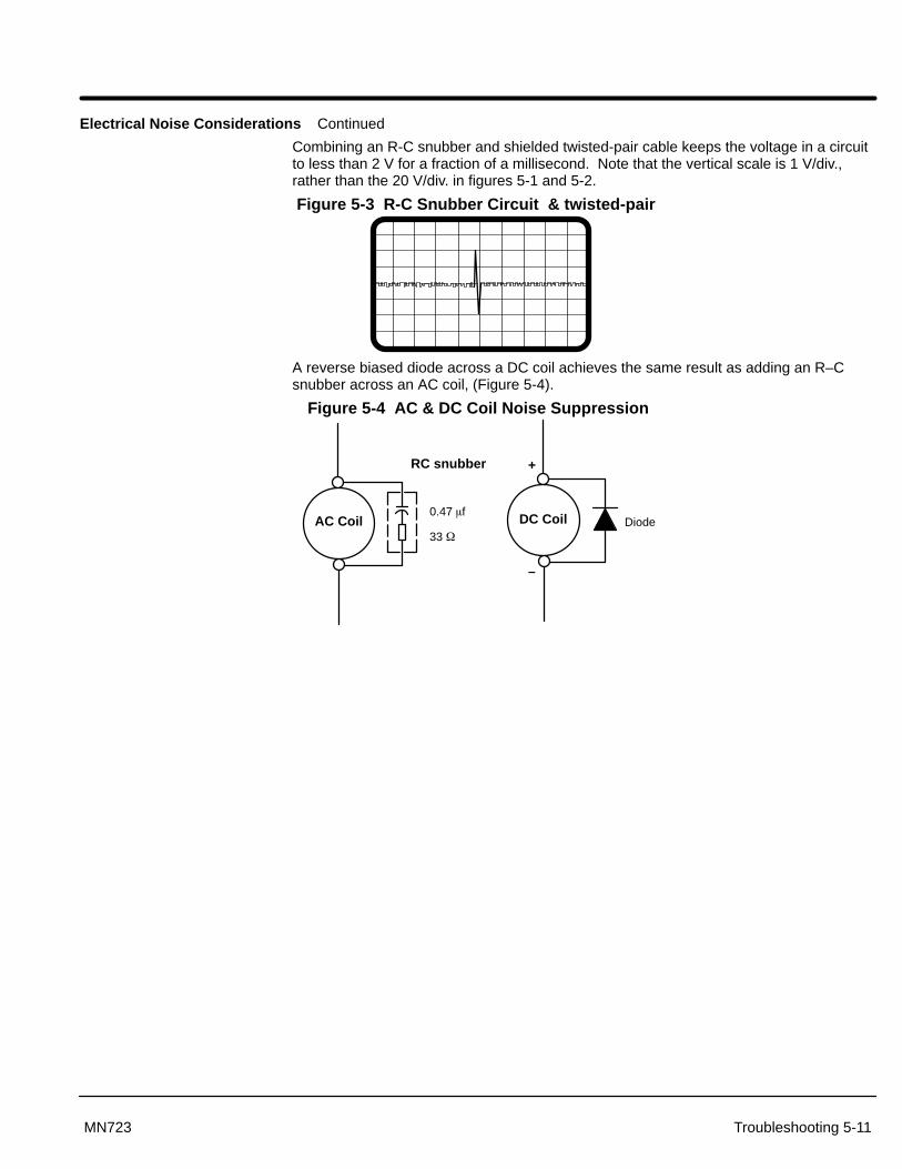
Section 1General Information
Troubleshooting 5-11MN723
Electrical Noise Considerations Continued
Combining an R-C snubber and shielded twisted-pair cable keeps the voltage in a circuitto less than 2 V for a fraction of a millisecond. Note that the vertical scale is 1 V/div.,rather than the 20 V/div. in figures 5-1 and 5-2.
Figure 5-3 R-C Snubber Circuit & twisted-pair
A reverse biased diode across a DC coil achieves the same result as adding an R–Csnubber across an AC coil, (Figure 5-4).
Figure 5-4 AC & DC Coil Noise Suppression
AC Coil DC Coil
RC snubber
0.47 �fDiode
–
+
33 �

Section 1General Information
5-12 Troubleshooting MN723
Electrical Noise Considerations Continued
Wires between Controls and Motors
Output leads from a typical 460 VAC drive controller contain rapid voltage rises createdby power semiconductors switching 650V in less than a microsecond, 1,000 to 10,000times a second. These noise signals can couple into sensitive drive circuits as shown inFigure 5-5. For this waveform, a transient induced in 1 ft. of wire adjacent to motor leadof a 10 hp, 460 VAC drive. Scope is set at 5 V/div. and 2 �sec/div.
Figure 5-5 10HP, 460VAC Drive
If the shielded pair cable is used, the coupling is reduced by nearly 90%, Figure 5-6.
Figure 5-6 10HP, 460VAC Drive, Shielded
The motor leads of DC motors contain similar voltage transients. The switching rate isabout 360 times a second. These noise transients can produce about 2V of noiseinduced in a wire adjacent to the motor lead. The noise induced by a 30HP, 500VDCDrive, is shown in Figure 5-7. Scope is set at 1 V/div. and 5 �sec/div.
Figure 5-7 30HP, 500VDC Drive
Again, replacing a single wire with a shielded pair cable reduces the induced noise to lessthan 0.3 V, Figure 5-8.
Figure 5-8 30HP, 500VDC Drive, Shielded

Section 1General Information
Troubleshooting 5-13MN723
Electrical Noise Considerations Continued
Even input AC power lines contain noise and can induce noise in adjacent wires. This isespecially severe with SCR controlled DC drives, current–source and six–step inverters.Figure 5-9 shows a transient induced in 1–ft. wire adjacent to the AC input power wire ofa 30 hp, DC drive. Scope is set at 500 mV/div. and 2�sec/div.
Figure 5-9 30HP, 500VDC Drive, Shielded
To prevent induced transient noise in signal wires, all motor leads and AC power linesshould be contained in rigid metal conduit, or flexible conduit. Do not place lineconductors and load conductors in same conduit. Use separate conduit for 3 phase inputwires and motor leads. The conduit should be grounded to form a shield to contain theelectrical noise within the conduit path. Signal wires - even ones in shielded cable shouldnever be placed in the conduit with motor power wires.
If flexible conduit is required, the wires should be shielded twisted-pair. Although thispractice gives better protection than unshielded wires, it lacks the protection offered byrigid metal conduit.
Special Drive Situations For severe noise situations, it may be necessary to reduce transient voltages in the wiresto the motor by adding load reactors. Load reactors are installed between the control andmotor. These are often required where a motor housing lacks the necessary shielding(typically linear motors mounted directly to machine frames) or where the power wires tomotors are contained in flexible cables.
Reactors are typically 3% reactance and are designed for the frequencies encountered inPWM drives. For maximum benefit, the reactors should be mounted in the driveenclosure with short leads between the control and the reactors. Baldor offers acomplete line of line and load reactors that will reduce ripple current and improve motorlife.
Drive Power Lines The same type of reactor installed on the load side of the control can also suppresstransients on incoming power lines. Connected on the line side of the drive, the reactorprotects the adjustable–speed drive from some transients generated by other equipmentand suppresses some of the transients produced by the drive itself.
Radio Transmitters Not a common cause of noise, radio frequency transmitters, such as commercialbroadcast stations, fixed short–wave stations, and mobile communications equipment(including walkie talkies) create electrical noise. The probability of this noise affecting anadjustable–speed drive increases with the use of open control enclosures, open wiring,and poor grounding.
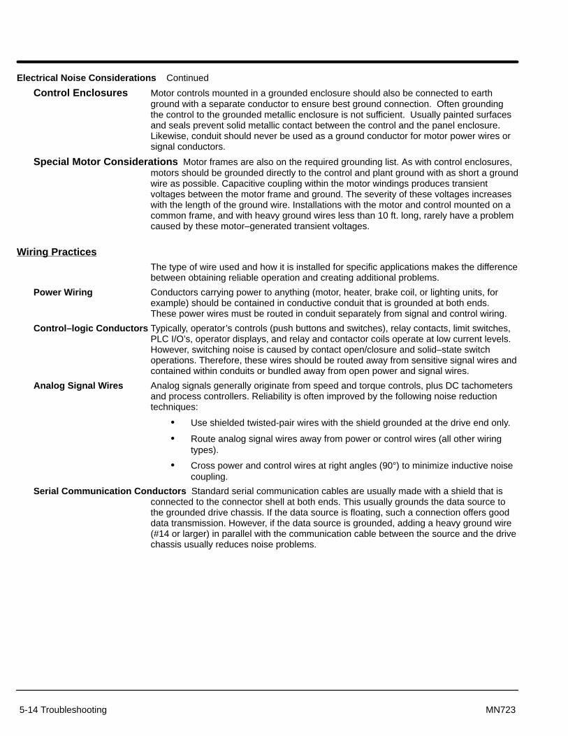
Section 1General Information
5-14 Troubleshooting MN723
Electrical Noise Considerations Continued
Control Enclosures Motor controls mounted in a grounded enclosure should also be connected to earthground with a separate conductor to ensure best ground connection. Often groundingthe control to the grounded metallic enclosure is not sufficient. Usually painted surfacesand seals prevent solid metallic contact between the control and the panel enclosure.Likewise, conduit should never be used as a ground conductor for motor power wires orsignal conductors.
Special Motor Considerations Motor frames are also on the required grounding list. As with control enclosures,motors should be grounded directly to the control and plant ground with as short a groundwire as possible. Capacitive coupling within the motor windings produces transientvoltages between the motor frame and ground. The severity of these voltages increaseswith the length of the ground wire. Installations with the motor and control mounted on acommon frame, and with heavy ground wires less than 10 ft. long, rarely have a problemcaused by these motor–generated transient voltages.
Wiring PracticesThe type of wire used and how it is installed for specific applications makes the differencebetween obtaining reliable operation and creating additional problems.
Power Wiring Conductors carrying power to anything (motor, heater, brake coil, or lighting units, forexample) should be contained in conductive conduit that is grounded at both ends.These power wires must be routed in conduit separately from signal and control wiring.
Control–logic Conductors Typically, operator’s controls (push buttons and switches), relay contacts, limit switches,PLC I/O’s, operator displays, and relay and contactor coils operate at low current levels.However, switching noise is caused by contact open/closure and solid–state switchoperations. Therefore, these wires should be routed away from sensitive signal wires andcontained within conduits or bundled away from open power and signal wires.
Analog Signal Wires Analog signals generally originate from speed and torque controls, plus DC tachometersand process controllers. Reliability is often improved by the following noise reductiontechniques:
• Use shielded twisted-pair wires with the shield grounded at the drive end only.
• Route analog signal wires away from power or control wires (all other wiringtypes).
• Cross power and control wires at right angles (90°) to minimize inductive noisecoupling.
Serial Communication Conductors Standard serial communication cables are usually made with a shield that isconnected to the connector shell at both ends. This usually grounds the data source tothe grounded drive chassis. If the data source is floating, such a connection offers gooddata transmission. However, if the data source is grounded, adding a heavy ground wire(#14 or larger) in parallel with the communication cable between the source and the drivechassis usually reduces noise problems.

Section 1General Information
Troubleshooting 5-15MN723
Optical Isolation Two methods of optical isolation are commonly used; optical couplers and fiber optics.
Optical Couplers Optical couplers, often referred to as opto couplers use a light transmitter and lightreceiver in the same unit to transmit data while electrically isolating two circuits. Thisisolation rejects some noise. The magnitude of noise rejection is usually specified by the“common mode rejection, dv/dt rating”. Typically, low cost opto couplers have a commonmode rejection of 100 to 500 V/�sec, which is adequate for most control logic signals.High performance opto couplers with common mode ratings up to 5,000 V/�sec areinstalled for the most severe noise environments.
Fiber Optics Special plastic or glass fiber strands transmit light over long as well as short distances.Because the fibers are immune to electromagnetic energy, the use of fiber optic bundleseliminate the problem of coupling noise into such circuits. These noise–free fiber opticcables can be run with power or motor conductors because noise cannot be inductively orcapacitively coupled into the fiber optic strands.
Plant Ground Connecting electrical equipment to a good ground is essential for safety and reliableoperation. In many cases, what is perceived as a ground is not ground. Result: equipment malfunctions or electrical shock hazard exists.
It may be necessary to retain the services of an electrical consultant, who is also alicensed professional engineer experienced in grounding practices to make the necessarymeasurements to establish if the plant ground is really grounded.

Section 1General Information
5-16 Troubleshooting MN723

Section 6Manual Tuning the Series 23H Control
Manual Tuning the Series 23H Control 6-1MN723
Manually Tuning the Control In some applications the drive cannot be accurately auto-tuned. In these cases, it isnecessary to calculate the values needed to tune the drive and manually enter thesecalculated parameter values.
Current Prop Gain Parameter This parameter is located in the Level 1, Brushless Control Block. The CurrentProp Gain parameter is normally autotuned when motor inductance is not known. Whereautotuning can’t be used, the proper manual setting for the proportional gain can becalculated by:
Current PROP Gain ��740 x L x �A�V��
VACWhere:
L = Line to neutral leakage inductance of the motor in mHVAC = Nominal line voltsA/V = The amps/volt scaling of the current feedback
Motor line to neutral leakage inductance can be obtained either from the motormanufacturer or for WYE connected motors, by measuring the line–to–line inductanceand dividing the measured value by two.
The A/V scaling for the controller can be found in the diagnostic information located in theDISPLAY MODE.
For most applications setting the Current Prop Gain parameter to a value of 20 will yieldadequate performance.
Current INT Gain Parameter This parameter is located in the Level 1, Brushless Control Block. The factory setting issuitable for essentially all systems. Do not change without factory approval.
Speed Prop Gain Parameter
The Speed Prop Gain parameter is located in the Level 1 Brushless Control Block. Thisgain may be increased or decreased to suit the application. Increasing the Speed PropGain parameter will result in faster response, excessive proportional gain will causeovershoot and ringing. Decreasing the Speed Prop Gain parameter will cause slowerresponse and decrease overshoot and ringing caused by excessive proportional gain.

Section 1General Information
6-2 Manual Tuning the Series 23H Control MN723
Speed Int Gain Parameter
The Speed Int Gain parameter located in the Level 1 Brushless Control Block may be setto any value from zero to 9.99 Hz. See also, PI Controller later in this section.
Setting the Speed Int Gain parameter to 0Hz removes integral compensation that resultsin a proportional rate loop. This selection is ideal for systems where overshoot must beavoided and substantial stiffness (ability of the controller to maintain commanded speeddespite varying torque loads) isn’t required.
Increasing values of the Speed Int Gain parameter increases the low frequency gain andstiffness of the controller, an excessive integral gain setting will cause overshoot fortransient speed commands and may lead to oscillation. If the Speed Prop Gainparameter and the Speed Int Gain parameter are set too high, an overshoot conditioncan also occur.
To manually tune the control, the following procedure is used:
1. Set the speed Int Gain parameter = 0 (remove integral gain).
2. Increase the Speed Prop Gain parameter setting until adequate response tostep speed commands is attained.
3. Increase the Speed Int Gain parameter setting to increase the stiffness of thedrive.
Note: It is convenient to monitor speed step response with a strip chart recorder orstorage oscilloscope connected to J1–6 or –7 with Level 1, Output BlockAnalog Out #1 or #2 set to ABS SPEED, 0 VDC = zero speed. See Section 3for a discussion of analog outputs.
PI Controller
Both the current and rate control loops are of the Proportional plus Integral type. If “E” isdefined to be the error signal,
E = Command – Feedback
then the PI controller operated on “E” as
Output = (Kp * E) + (Ki � E dt)
where Kp is the proportional gain of the system and Ki is the integral gain of the system.
The transfer function (output /E) of the controller using 1/s (Laplace Operator) to denotethe integral,
Output/E = Kp + Kl / s = Kp (s + Ki/Kp) /s.
The second equation shows that the ratio of Ki/Kp is a frequency in radians/sec. In theBaldor Control, the integral gain has been redefined to be,
Kl = (Ki / Kp) / (2�) Hz,
and the transfer function is,
Output/E = Kp (s + 2�Kl) / s.
This sets the integral gain as a frequency in Hz. As a rule of thumb, set this frequencyabout 1/10 of the bandwidth of the control loop.
The proportional gain sets the open loop gain of the system, the bandwidth (speed ofresponse) of the system. If the system is excessively noisy, it is most likely due to theproportional gain being set too high.

Section 7Specifications, Ratings & Dimensions
Specifications, Ratings & Dimensions 7-1MN723
Specifications:
Power 0.75 - 37.2kW (1-50 HP) @ 230VAC0.75 - 186.5kW (1-250 HP) @ 460VAC
Input Frequency 50/60 HZ ± 5%
Output Voltage 0 to Maximum Input VAC
Output Current See Ratings Table
Service Factor 1.0
Duty Continuous
Overload Capacity Constant Torque Mode: 170-200% for 3 secs150% for 60 secs
Variable Torque Mode: 115% for 60 secs
Speed Command Potentiometer 5k� or 10k�, 0.5Watt
Operating Conditions:
Voltage Range: 230 VAC Models460 VAC Models
180-264 VAC 3� 60 Hz / 180-230 VAC 3� 50 Hz340-528 VAC 3� 60 Hz / 380-415 VAC 3� 50 Hz
Input Line Impedance: 3% Minimum Required
Ambient Operating Temperature: –10 to +40 °CDerate Output 2% per °C over 40 °C to 55 °C Max
Rated Storage Temperature: – 30 °C to +65 °C
Enclosure: NEMA 1: E and EO (suffix) ModelsNEMA 4X indoor: W (suffix) Models
Humidity: NEMA 1: 10 to 90% RH Non-CondensingNEMA 4X indoor: To 100% RH
Altitude: Sea level to 3300 Feet (1000 Meters)Derate 2% per 1000 Feet (303 Meters) above 3300 Feet
Shock: 1G
Vibration: 0.5G at 10Hz to 60Hz
Resolver Feedback:
Sine & Cosine Inputs 2VRMS ±10% (Maximum Coupled)
Excitation (Reference Voltage) 4VRMS @ 10kHz
Resolver Transformation Ratio TR = 0.5 only

Section 1General Information
7-2 Specifications, Ratings & Dimensions MN723
Keypad Display:
Display Backlit LCD Alphanumeric 2 Lines x 16 Characters
Keys 12 key membrane with tactile response
Functions Output status monitoringDigital speed controlParameter setting and displayDiagnostic and Fault log displayMotor run and jogLocal/Remote toggle
LED Indicators Forward run commandReverse run commandStop commandJog active
Remote Mount 100 feet (30.3m) max from control
Control Specifications:
Control Method PWM
Feedback Resolution 12 bit Resolver/Digital conversion
Velocity Loop Bandwidth Adjustable to 30 Hz
Current Loop Bandwidth Adjustable to 1500 Hz
Maximum Output Frequency 1000 Hz
Quiet PWM Frequency Setting Full rating 1-8 kHz PWM frequency, Adjustable to 16 kHz with linear derating (between 8 - 16kHz) to 30% at 16 kHz
Standard PWM Frequency Setting Full rating 1-2.5 kHz PWM frequency, Adjustable to 5 kHz with linear derating (between 2.5 - 5kHz) to 10% at 5 kHz
Selectable Operating Modes KeypadStandard 3 Wire ControlTwo Wire Control with 15 Preset SpeedsBipolar SpeedSerial Process
Differential Analog Input:
Common Mode Rejection 40 db
Full Scale Range ±5VDC, ±10VDC, 4-20 mA
Auto-selectable Resolutions 9 bits + sign
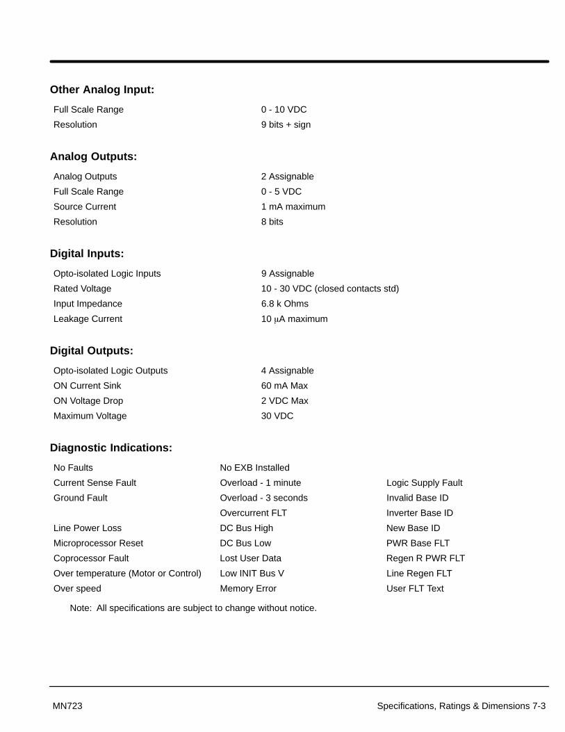
Section 1General Information
Specifications, Ratings & Dimensions 7-3MN723
Other Analog Input:
Full Scale Range 0 - 10 VDC
Resolution 9 bits + sign
Analog Outputs:
Analog Outputs 2 Assignable
Full Scale Range 0 - 5 VDC
Source Current 1 mA maximum
Resolution 8 bits
Digital Inputs:
Opto-isolated Logic Inputs 9 Assignable
Rated Voltage 10 - 30 VDC (closed contacts std)
Input Impedance 6.8 k Ohms
Leakage Current 10 �A maximum
Digital Outputs:
Opto-isolated Logic Outputs 4 Assignable
ON Current Sink 60 mA Max
ON Voltage Drop 2 VDC Max
Maximum Voltage 30 VDC
Diagnostic Indications:
No Faults No EXB Installed
Current Sense Fault Overload - 1 minute Logic Supply Fault
Ground Fault Overload - 3 seconds Invalid Base ID
Overcurrent FLT Inverter Base ID
Line Power Loss DC Bus High New Base ID
Microprocessor Reset DC Bus Low PWR Base FLT
Coprocessor Fault Lost User Data Regen R PWR FLT
Over temperature (Motor or Control) Low INIT Bus V Line Regen FLT
Over speed Memory Error User FLT Text
Note: All specifications are subject to change without notice.

Section 1General Information
7-4 Specifications, Ratings & Dimensions MN723
Ratings Series 23H Stock Products
CATALOG INPUT SIZESTANDARD 2.5 kHz PWM QUIET 8.0 kHz PWM
CATALOGNO.
INPUTVOLT
SIZE CONSTANT TORQUE VARIABLE TORQUE CONSTANT TORQUE VARIABLE TORQUENO. VOLTIC IP KW HP IC IP KW HP IC IP KW HP IC IP KW HP
SD23H2A03–E 230 A 3 6 .56 .75 4 5 .75 1 4 8 .75 1 7 8 1.5 2
SD23H2A04–E 230 A 4 8 .75 1 7 8 1.5 2 7 14 1.5 2 10 12 2.2 3
SD23H2A07–E 230 A 7 14 1.5 2 10 12 2.2 3 10 20 2.2 3 16 19 3.7 5
SD23H2A10–E 230 A 10 20 2.2 3 16 19 3.7 5 16 32 3.7 5 22 25 5.5 7.5
SD23H2A15–E 230 B 16 32 3.7 5 22 25 5.5 7.5 22 44 5.5 7.5 28 32 7.4 10
SD23H2A22–E 230 B 22 44 5.5 7.5 28 32 7.4 10 28 56 7.4 10 42 48 11.1 15
SD23H2A28–E 230 B 28 56 7.4 10 42 48 11.1 15 42 84 11.1 15 42 48 11.1 15
SD23H2A42–ER 230 C 42 92 11.1 15 54 62 14.9 20 55 100 14.9 20 68 78 18.6 25
SD23H2A55–ER 230 C 54 92 14.9 20 68 78 18.6 25 68 116 18.6 25 80 92 22.3 30
SD23H4A02–E 460 A 2 4 .75 1 4 5 1.5 2 4 8 1.5 2 5 6 2.2 3
SD23H4A04–E 460 A 4 8 1.5 2 5 6 2.2 3 5 10 2.2 3 8 10 3.7 5
SD23H4A05–E 460 A 5 10 2.2 3 8 10 3.7 5 8 16 3.7 5 11 13 5.5 7.5
SD23H4A08–E 460 B 8 16 3.7 5 11 13 5.5 7.5 11 22 5.5 7.5 14 17 7.4 10
SD23H4A11–E 460 B 11 22 5.5 7.5 14 17 7.4 10 14 28 7.4 10 21 25 11.1 15
SD23H4A15–E 460 B 15 30 7.4 10 21 25 11.1 15 21 42 11.1 15 27 31 14.9 20
SD23H4A22–ER 460 C 21 46 11.1 15 27 31 14.9 20 27 54 14.9 20 34 39 18.6 25
SD23H4A30–ER 460 C 27 46 14.9 20 34 39 18.6 25 34 58 18.6 25 40 46 22.3 30
Note: –E, –EO= NEMA 1 Enclosure–W= NEMA 4X Indoor Enclosure–MO= Protected Chassis (not NEMA1)

Section 1General Information
Specifications, Ratings & Dimensions 7-5MN723
Terminal Tightening Torque Specifications
Table 7-4 Tightening Torque Specifications
230VACTightening Torque
230VACCatalo g Numbers Power TB1 Ground Control J1 B+/R1; B+; B–; or R2 D1/D2Catalog Numbers
Lb-in Nm Lb-in Nm Lb-in Nm Lb-in Nm Lb-in Nm
SD23H2A03–E 8 0.9 15 1.7 4.5 0.5 8 0.9
SD23H2A04–E 8 0.9 15 1.7 4.5 0.5 8 0.9
SD23H2A07–E 8 0.9 15 1.7 4.5 0.5 8 0.9
SD23H2A10–E 8 0.9 15 1.7 4.5 0.5 8 0.9
SD23H2A15–E 20 2.5 15 1.7 4.5 0.5 20 2.5
SD23H2A22–E 20 2.5 15 1.7 4.5 0.5 20 2.5
SD23H2A30–ER 35 4 50 5.6 4.5 0.5 35 4
SD23H2A45–ER 35 4 50 5.6 7 0.8 35 4
SD23H2A55–ER 35 4 50 5.6 7 0.8 35 4
460VACTightening Torque
460VACCatalo g Numbers Power TB1 Ground Control J1 B+/R1; B+; B–; or R2 D1/D2Catalog Numbers
Lb-in Nm Lb-in Nm Lb-in Nm Lb-in Nm Lb-in Nm
SD23H4A02–E 8 0.9 15 1.7 4.5 0.5 8 0.9
SD23H4A04–E 8 0.9 15 1.7 4.5 0.5 8 0.9
SD23H4A05–E 8 0.9 15 1.7 4.5 0.5 8 0.9
SD23H4A08–E 20 2.5 20 2.5 4.5 0.5 20 2.5
SD23H4A11–E 20 2.5 20 2.5 4.5 0.5 20 2.5
SD23H4A15–ER 35 4 50 5.6 4.5 0.5 35 4
SD23H4A22–ER 35 4 50 5.6 7 0.8 35 4
SD23H4A30–ER 35 4 20 2.5 7 0.8 35 4 3.5 0.4
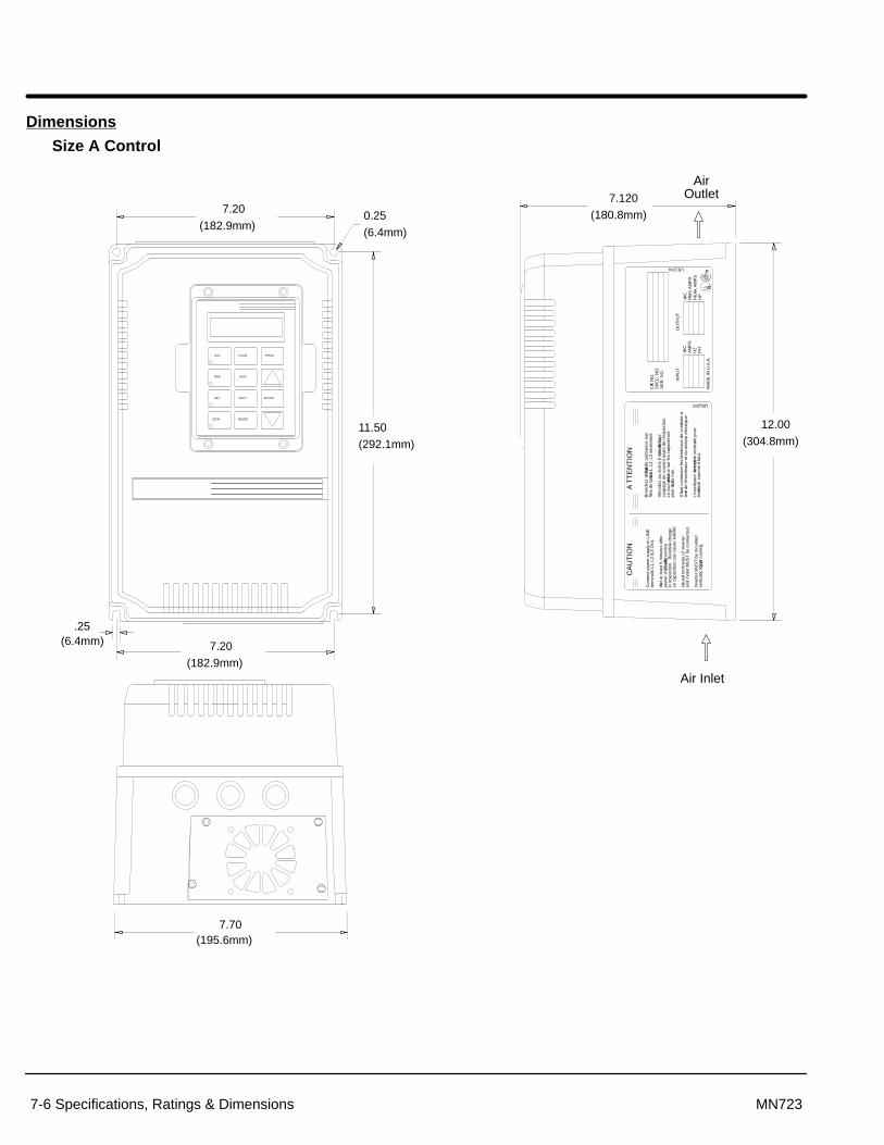
Section 1General Information
7-6 Specifications, Ratings & Dimensions MN723
Dimensions
Size A Control
11.50
(292.1mm)
7.20
(182.9mm)
.25(6.4mm)
LOCAL
SHIFT
DISP
RESET
PROG
ENTER
JOG
STOP
REV
FWD
7.20
(182.9mm)0.25
(6.4mm)
terre
de
l’inv
ertis
eur
et d
u m
oteu
r el
ectr
ique
.
Bra
nche
z la
four
nitu
re de
pui
ssan
ce a
uxfil
es d
e la
bor
ne L
1, L
2, L
3 se
ulem
ent.
Atte
ndez
au
moi
ns 5
min
utes
apr
es d
e la
coup
age
de c
oura
nt a
vant
de
I’ins
pect
ion.
Le c
oura
nt r
esid
ue s
ur le
s ca
paci
teur
s
AT
TE
NT
ION
Il fa
ut c
onne
cter
les
term
inau
x de
con
duite
a
L’in
vert
iseu
r do
it et
re
mon
te v
ertic
ale
pour
12.00
(304.8mm)
Grou
nd te
rmin
als
of in
vert
er
on c
apac
itors
can
cau
se H
AR
M.
or in
spec
tion.
Res
idul
e ch
arge
pow
er s
hut–
off b
efore
serv
ice
Wait
at le
ast 5
min
utes
afte
r
term
inal
s L1
, L2,
L3
ON
LY.
Con
nect
pow
er s
uppl
y to
LIN
E
CA
UT
ION
peut
faire du
mal
.
vert
ical
ly f
or p
rop
er c
oolin
g.In
vert
er M
US
T b
e m
ount
ed
and
mot
or M
US
T b
e co
nnec
ted.
se ref
roidi
r co
mm
e il
faut
.
7.120
(180.8mm)
INP
UT
SE
R. N
O.
CAT.
NO
.S
PE
C. N
O.
OU
TP
UT
LB1204
PE
AK
AM
PS
RM
S A
MP
S
LB1203
MA
DE
IN U
.S.A
.
HZ
VAC
AM
PS
PH
VAC
HP
RR
7.70(195.6mm)
Air Inlet
AirOutlet

Section 1General Information
Specifications, Ratings & Dimensions 7-7MN723
Size A Control – Through–Wall Mounting KT0000A01
BALDOR
BALDOR
Gasket
Steel Plate
Standoffs1/2 x 2-1/2
10–32 x 0.75″Truss screw &washer
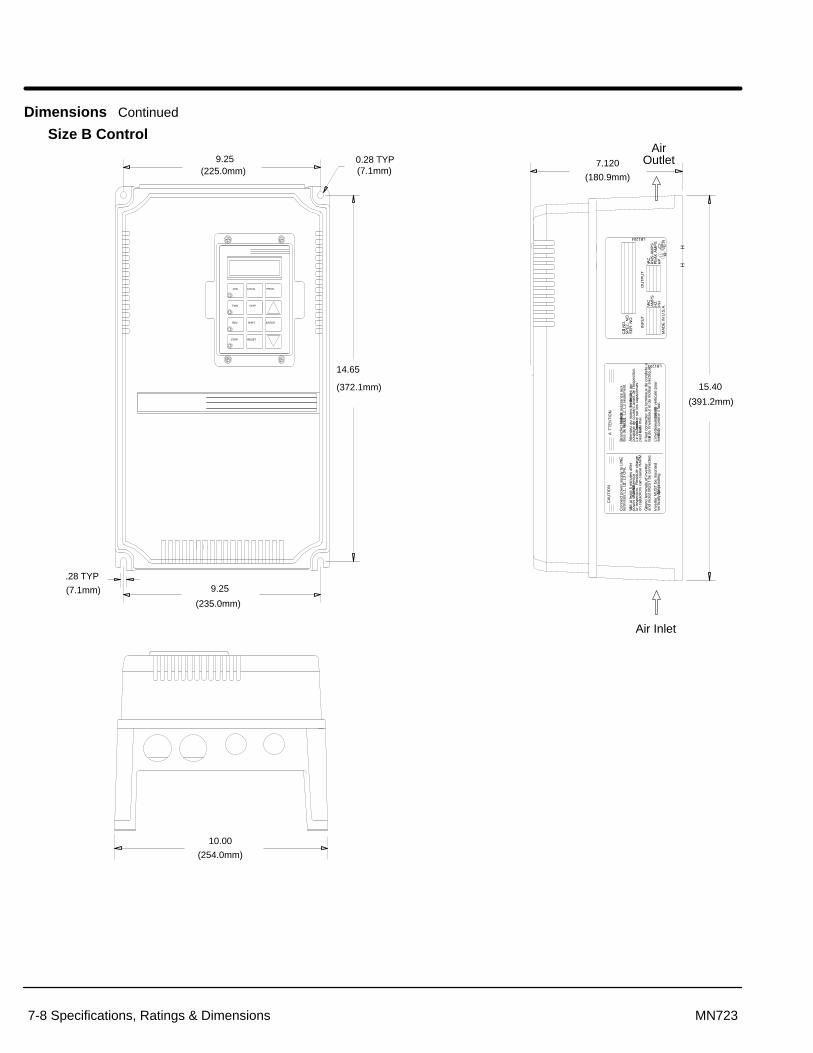
Section 1General Information
7-8 Specifications, Ratings & Dimensions MN723
Dimensions Continued
Size B Control
.28 TYP
(7.1mm)
14.65
(372.1mm)
9.25
(235.0mm)
PROG
ENTER
9.25(225.0mm)
0.28 TYP(7.1mm)
SHIFT
RESETSTOP
REV
LOCAL
DISPFWD
JOG
terre
de
l’inv
ertis
eur
et d
u m
oteu
r el
ectr
ique
.
Bra
nche
z la
four
nitu
re de
pui
ssan
ce a
uxfil
es d
e la
bor
ne L
1, L
2, L
3 se
ulem
ent.
Atte
ndez
au
moi
ns 5
min
utes
apr
es d
e la
coup
age
de c
oura
nt a
vant
de
I’ins
pect
ion.
Le c
oura
nt r
esid
ue s
ur le
s ca
paci
teur
s
AT
TE
NT
ION
Il fa
ut c
onne
cter
les
term
inau
x de
con
duite
a
L’in
vert
iseu
r do
it et
re
mon
te v
ertic
ale
pour 15.40
(391.2mm)
Grou
nd te
rmin
als
of in
vert
er
on c
apac
itors
can
cau
se H
AR
M.
or in
spec
tion.
Res
idul
e ch
arge
pow
er s
hut–
off b
efore
serv
ice
Wait
at le
ast 5
min
utes
afte
r
Con
nect
pow
er s
uppl
y to
LIN
E
CA
UT
ION
term
inal
s L1
, L2,
L3
ON
LY.
peut
fair
e du
mal
.
and
mot
or M
US
T b
e co
nnec
ted.
vert
ical
ly f
or p
rop
er c
oolin
g.In
vert
er M
US
T b
e m
ount
edse
refroi
dir
com
me
il fa
ut.
LB1204
7.120
(180.9mm)
INP
UT
SE
R. N
O.
CAT.
NO
.S
PE
C. N
O.
H
OU
TP
UT
H
PE
AK
AM
PS
RM
S A
MP
S
MA
DE
IN U
.S.A
.
LB1203
PH
HZ
VAC
AM
PS
VAC
HP
RR
10.00
(254.0mm)
Air Inlet
AirOutlet

Section 1General Information
Specifications, Ratings & Dimensions 7-9MN723
Size B Control – Through–Wall Mounting KT0000A00
BALDOR
BALDOR
Gasket
Steel Plate
Standoffs1/2 x 2-1/2
10–32 x 0.75″Truss screw &washer

Section 1General Information
7-10 Specifications, Ratings & Dimensions MN723
Dimensions Continued
Size C Control
CustomerPower Connections
AirOutlet
.28 (7.0mm)2 Places
Air Inlet
One or Two Fan(s)(119mm)
.28 (7.0mm)2 Places
10.75(273.0 mm)
11.50(292.0 mm)
.38(9.5 mm)
.38(9.5 mm)
17.00(433.0 mm)
17.75(451 mm)
18.50(470.0 mm)
9.50(241.5 mm)
9.50(241.5 mm)
PROG
ENTERSHIFT
RESETSTOP
REV
LOCAL
DISPFWD
JOG

Section 1General Information
Specifications, Ratings & Dimensions 7-11MN723
Size C2 Control
0.000.4930.903
0.00
00.
260
0.91
6
8.67
5
9.34
0
0.250 Dia.2 Places
0.280 Dia.2 Places
15.66516.07516.568
0.00
0
0.91
6
8.67
5
4.95(125.7)
4.71(119.6)
9.66(245.4)
Wall MountMtg. Flange
Through WallMtg. Flange
16.98(431.3)
10.50(266.7)
Air Inlet
Air Outlet
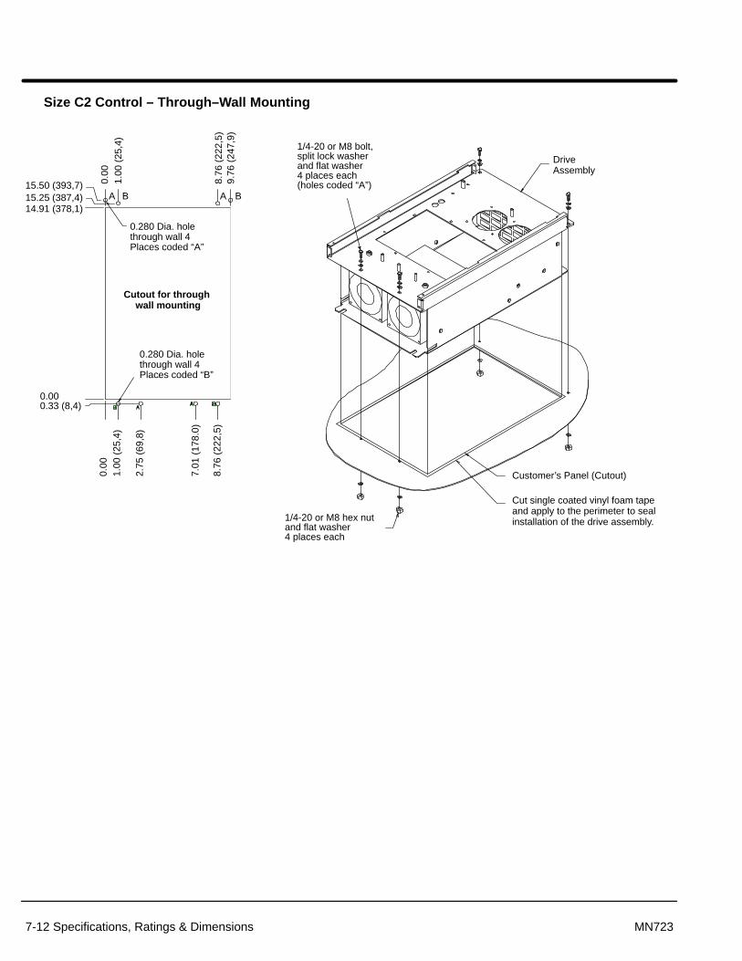
Section 1General Information
7-12 Specifications, Ratings & Dimensions MN723
Size C2 Control – Through–Wall Mounting
15.25 (387,4)
0.280 Dia. holethrough wall 4Places coded “A”
14.91 (378,1)
Cutout for through wall mounting
0.280 Dia. holethrough wall 4Places coded “B”
0.000.33 (8,4)
0.00
1.00
(25
,4)
2.75
(69
,8)
7.01
(17
8.0)
8.76
(22
2,5)
0.00
1.00
(25
,4)
9.76
(24
7,9)
8.76
(22
2,5)
15.50 (393,7)A B A B
DriveAssembly
1/4-20 or M8 bolt, split lock washerand flat washer 4 places each(holes coded “A”)
1/4-20 or M8 hex nutand flat washer 4 places each
Customer’s Panel (Cutout)
Cut single coated vinyl foam tapeand apply to the perimeter to sealinstallation of the drive assembly.
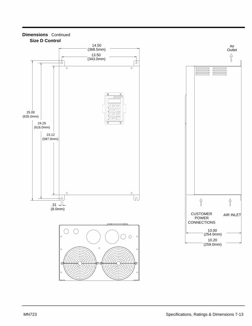
Section 1General Information
Specifications, Ratings & Dimensions 7-13MN723
Dimensions Continued
Size D Control
CUSTOMERPOWER
CONNECTIONS
AIR INLET
13.50(343.0mm)
14.50(368.5mm)
25.00(635.0mm)
10.20(259.0mm)
10.00(254.0mm)
.31(8.0mm)
23.12(587.0mm)
24.25(616.0mm)
AirOutlet
PROG
ENTERSHIFT
RESETSTOP
REV
LOCAL
DISPFWD
JOG

Section 1General Information
7-14 Specifications, Ratings & Dimensions MN723
Dimensions Continued
Size E Control
5.75(146mm)
6.25(159mm)
30.00(762mm)
.38
.38(9.5mm) 17.70
(450mm)
Thru–wallMounting Flange
SurfaceMountingFlange(9.5mm)
Air Inlet
AirOutlet
PROG
ENTERSHIFT
RESETSTOP
REV
LOCAL
DISPFWD
JOG
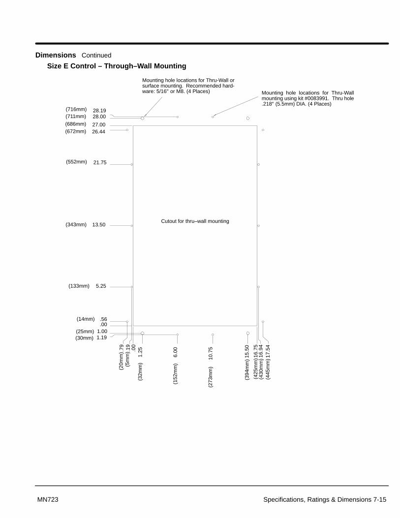
Section 1General Information
Specifications, Ratings & Dimensions 7-15MN723
Dimensions Continued
Size E Control – Through–Wall Mounting
Cutout for thru–wall mounting
(20m
m)
(5m
m)
(32m
m)
(152
mm
)
(273
mm
)
(394
mm
)
(425
mm
)(4
30m
m)
(445
mm
)
.001.001.19
.56
5.25
13.50
21.75
26.4427.00
28.1928.00
.00
.19
.79
1.25
6.00
10.7
5
15.5
0
17.5
416
.94
16.7
5
(25mm)(30mm)
(14mm)
(133mm)
(343mm)
(552mm)
(672mm)(686mm)
(711mm)(716mm)
Mounting hole locations for Thru-Wall orsurface mounting. Recommended hard-ware: 5/16″ or M8. (4 Places) Mounting hole locations for Thru-Wall
mounting using kit #0083991. Thru hole.218″ (5.5mm) DIA. (4 Places)

Section 1General Information
7-16 Specifications, Ratings & Dimensions MN723
Dimensions Continued
Size E Control – Through–Wall Mounting Continued
Controller Assembly
Customer’s Panel
Cut foam tape and applyto perimeter of opening(to seal installation ofcontroller)
Bracket2 Places
Bracket2 Places
14 Places
4 Places
Parts List - Thru–Wall Mounting Kit No. V0083991
QTY Part No. Description2 V1083991 Bracket, small (left & right)2 V1083992 Bracket, Large (top & bottom)14 V6300710 Screw, 10-32 x 5/814 V6420010 Lock Washer No. 104 V6390205 Hex Bolt 5/16-18 x 5/84 V6420032 Lock Washer 5/164 V6410132 Flat Washer 5/161 C6990204 Tape, Single coated vinyl – 3.0 Yards (2.74m)
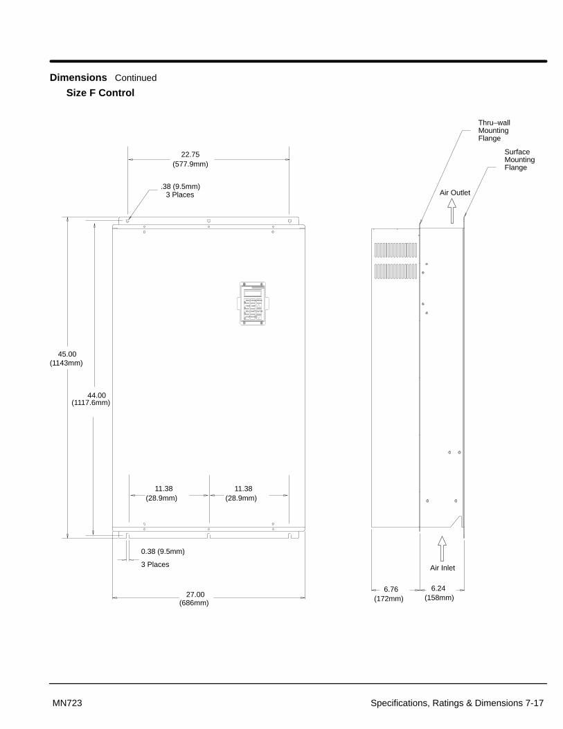
Section 1General Information
Specifications, Ratings & Dimensions 7-17MN723
Dimensions Continued
Size F Control
.38 (9.5mm)3 Places
Thru–wallMountingFlange
SurfaceMountingFlange
27.00 6.76
(172mm) 6.24
(158mm)
0.38 (9.5mm)
3 Places
45.00
22.75(577.9mm)
11.38(28.9mm)
11.38(28.9mm)
(1143mm)
44.00(1117.6mm)
(686mm)
Air Inlet
Air Outlet
PROG
ENTERSHIFT
RESETSTOP
REV
LOCAL
DISPFWD
JOG

Section 1General Information
7-18 Specifications, Ratings & Dimensions MN723
Dimensions Continued
Size F Control – Through–Wall Mounting
.00
.00
41.98
1.03.26
1.24
4.99
11.11
12.99
20.99
28.99
30.86
36.99
40.74
43.0142.24
AA A
A A A
B B B
B
A
B
A
A
B
A
B
A
B
BBBB
B
A
B
A
A
B
A
B
A
B
B
Mounting hole locations for Thru-Wall mountingor without thru-wall mounting kit #0084001.Thru hole .218″ (5.5mm) DIA. (16 Places,coded A)
Mounting hole locations for Thru-Wall mountingusing kit #0084001. Thru hole .218″ (5.5mm)DIA. (18 Places, coded B)
Cutout for thru–wall mounting
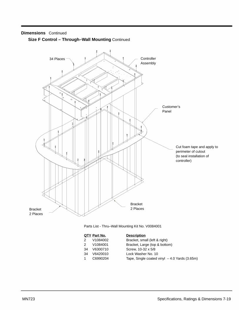
Section 1General Information
Specifications, Ratings & Dimensions 7-19MN723
Dimensions Continued
Size F Control – Through–Wall Mounting Continued
ControllerAssembly
Customer’sPanel
Cut foam tape and apply toperimeter of cutout (to seal installation ofcontroller)
Bracket2 Places
34 Places
Bracket2 Places
Parts List - Thru–Wall Mounting Kit No. V0084001
QTY Part No. Description2 V1084002 Bracket, small (left & right)2 V1084001 Bracket, Large (top & bottom)34 V6300710 Screw, 10-32 x 5/834 V6420010 Lock Washer No. 101 C6990204 Tape, Single coated vinyl – 4.0 Yards (3.65m)

Section 1General Information
7-20 Specifications, Ratings & Dimensions MN723
Dimensions Continued
Size G Control 3.72(94,6)
2.66(67,6)
Removable ConduitMounting Plates(Customer Power Connections)
24.00(609,6)
31.50(800)
VECTOR DRIVE
90.55(2300)
93.00(2362)
4.00(101,6)
47.25(1200)
23.63(600)
AirOutlet
AirInletGrills(4)
8.63 (219)
8.63 (219)12.41 (315)

Appendix A
Appendix A-1MN723
Dynamic Braking (DB) Hardware Whenever a motor is abruptly stopped or forced to slow down quicker than ifallowed to coast to a stop, the motor becomes a generator. This energy appears on theDC Bus of the control and must be dissipated using dynamic braking hardware. Dynamicbraking (DB) hardware can be a resistor or transistor load. Table A-1 provides a matrix ofDB turn ON and turn OFF voltages.
Table A-1
Parameter Description Control Input Voltage
Nominal Voltage 230VAC 460VAC
Overvoltage Fault (Voltage exceeded) 400VDC 800VDC
DB ON Voltage 381VDC 762VDC
DB Upper Tolerance Peak * 388VDC 776VDC
DB OFF Voltage 375VDC 750VDC
* DB Upper Tolerance Peak � 1.02 x 2� x VL�L
Braking torque and time should not exceed the available drive braking torque and timerating. The drive braking torque is limited to the available peak current and peak currenttime rating of the control. If the peak current or peak current time limit is exceeded duringbraking, the control may trip on an over voltage or a regen power fault. Selecting anoversized control or a line regenerative control should be considered in these cases.
Selection Procedure
1. Calculate the watts to be dissipated using the following formulas for theappropriate load type.
2. Identify the control model number and determine which braking hardware isrequired based on the model number suffix: E, EO, ER, MO or MR.
3. Select appropriate braking hardware from Baldor 501 Catalog or Tables A-2,A-3 and A-4.
Hoisting Load Calculations
1. Calculate braking duty cycle:
Duty Cycle �
Lowering TimeTotal Cycle Time
2. Calculate braking watts to be dissipated in dynamic braking resistors:
Watts �
duty cycle � lbs � FPM � efficiency44
where: lbs = weight of loadFPM = Feet Per Minuteefficiency = mechanical efficiency
i.e., 95% = 0.95
Continued on next page.

Section 1General Information
A-2 Appendix A MN723
Dynamic Braking (DB) Hardware Continued
General Machinery Load Calculations:
1. Calculate braking duty cycle:
Duty Cycle �
Braking TimeTotal Cycle Time
2. Calculate deceleration torque:
TDecel �
RPM change � Wk2
308 � time� Friction(Lb.Ft.)
where: TDecel = Deceleration torque in Lb.-ft. Wk2 = Inertia in Lb.ft.2 time = In seconds
3. Calculate watts to be dissipated in dynamic braking resistor:
Watts � TDecel � (Smax � Smin) � Duty Cycle � (0.0712)
where: Smax = Speed to start braking Smin = Speed after braking
4. Multiply watts calculated in step 3 by 1.25 to allow for unanticipated loads(safety factor).

Section 1General Information
Appendix A-3MN723
Dynamic Braking (DB) Hardware Continued
Catalog Numbers with an “E” Suffix
These controls are equipped with a factory installed dynamic brake transistor and brakeresistor(s). Size A controls have 400 watts and size B controls have 800 watts ofdissipation. These can provide 100% braking torque for 6 seconds of a 20% braking dutycycle. Should additional braking capacity be required an optional externally mountedRGA brake resistor can be used in lieu of the internal resistors. See RGA assemblies.
Catalog Numbers with an “ER” or “MR” Suffix
These controls include a factory installed dynamic braking transistor. If dynamic brakingis required, use an optional external RGA brake resistor. See RGA assemblies.
Catalog Numbers with an “EO” or “MO” Suffix
No dynamic braking hardware is installed in these controls. If dynamic braking isrequired, an optional RBA assembly or a combination of RTA and RGA assembliesshould be added. The RBA assembly provides up to 4,000 watts dynamic brakingcapacity. Should more capacity be required, a combination of an RTA (DB transistor) andRGA (DB resistor) should be used. Refer to RBA, RTA and RGA Assemblies description.
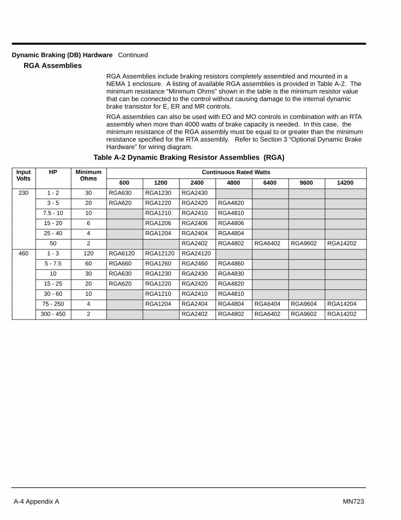
Section 1General Information
A-4 Appendix A MN723
Dynamic Braking (DB) Hardware Continued
RGA AssembliesRGA Assemblies include braking resistors completely assembled and mounted in aNEMA 1 enclosure. A listing of available RGA assemblies is provided in Table A-2. Theminimum resistance “Minimum Ohms” shown in the table is the minimum resistor valuethat can be connected to the control without causing damage to the internal dynamicbrake transistor for E, ER and MR controls.
RGA assemblies can also be used with EO and MO controls in combination with an RTAassembly when more than 4000 watts of brake capacity is needed. In this case, theminimum resistance of the RGA assembly must be equal to or greater than the minimumresistance specified for the RTA assembly. Refer to Section 3 “Optional Dynamic BrakeHardware” for wiring diagram.
Table A-2 Dynamic Braking Resistor Assemblies (RGA)
InputVolts
HP MinimumOhms
Continuous Rated WattsVolts Ohms
600 1200 2400 4800 6400 9600 14200
230 1 - 2 30 RGA630 RGA1230 RGA2430
3 - 5 20 RGA620 RGA1220 RGA2420 RGA4820
7.5 - 10 10 RGA1210 RGA2410 RGA4810
15 - 20 6 RGA1206 RGA2406 RGA4806
25 - 40 4 RGA1204 RGA2404 RGA4804
50 2 RGA2402 RGA4802 RGA6402 RGA9602 RGA14202
460 1 - 3 120 RGA6120 RGA12120 RGA24120
5 - 7.5 60 RGA660 RGA1260 RGA2460 RGA4860
10 30 RGA630 RGA1230 RGA2430 RGA4830
15 - 25 20 RGA620 RGA1220 RGA2420 RGA4820
30 - 60 10 RGA1210 RGA2410 RGA4810
75 - 250 4 RGA1204 RGA2404 RGA4804 RGA6404 RGA9604 RGA14204
300 - 450 2 RGA2402 RGA4802 RGA6402 RGA9602 RGA14202
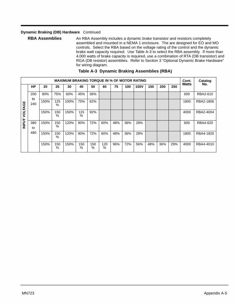
Section 1General Information
Appendix A-5MN723
Dynamic Braking (DB) Hardware Continued
RBA Assemblies An RBA Assembly includes a dynamic brake transistor and resistors completelyassembled and mounted in a NEMA 1 enclosure. The are designed for EO and MOcontrols. Select the RBA based on the voltage rating of the control and the dynamicbrake watt capacity required. Use Table A-3 to select the RBA assembly. If more than4,000 watts of brake capacity is required, use a combination of RTA (DB transistor) andRGA (DB resistor) assemblies. Refer to Section 3 “Optional Dynamic Brake Hardware”for wiring diagram.
Table A-3 Dynamic Braking Assemblies (RBA)
MAXIMUM BRAKING TORQUE IN % OF MOTOR RATING Cont.Watts
CatalogNo
HP 20 25 30 40 50 60 75 100 150V 150 200 250Watts No.
200to
90% 75% 60% 45% 36% 600 RBA2-610
TAG
E
to240
150% 125%
100% 75% 62% 1800 RBA2-1806
T V
OLT
A
150% 150%
150% 115%
92% 4000 RBA2-4004
INP
UT
380to
150% 150%
120% 90% 72% 60% 48% 36% 28% 600 RBA4-620
480 150% 150%
120% 90% 72% 60% 48% 36% 28% 1800 RBA4-1820
150% 150%
150% 150%
150%
120%
96% 72% 56% 48% 36% 29% 4000 RBA4-4010

Section 1General Information
A-6 Appendix A MN723
Dynamic Braking (DB) Hardware Continued
RTA Assemblies RTA assemblies include a dynamic brake transistor and gate driver circuit boardcompletely assembled and mounted in a NEMA 1 enclosure. Brake resistors are notincluded in the RTA assembly. Each RTA assembly is designed to be used with an RGAdynamic brake resistor assembly. The minimum resistance of the RGA assembly mustbe equal to or greater than the minimum resistance specified for the RTA assembly.Select the RTA based on the voltage rating of the control and HP which provides thedynamic brake watt capacity required. Use Table A-4 to select the RTA assembly.Refer to Section 3 “Optional Dynamic Brake Hardware” for wiring diagram.
Table A-4 Dynamic Braking Transistor Assemblies (RTA)
HP MAXIMUM BRAKING TORQUE IN % OF MOTOR RATING
208 - 230 VAC 380 - 480 VAC
20 150% 150% 150% 150% 150% 150% 150%
25 125% 150% 150% 150% 150% 150% 150%
30 100% 150% 150% 120% 150% 150% 150%
40 75% 115% 150% 90% 150% 150% 150%
50 62% 92% 150% 72% 150% 150% 150%
60 60% 150% 150% 150%
75 48% 96% 150% 150%
100 36% 72% 150% 150%
150V 28% 56% 150% 150%
150 48% 126% 150%
200 36% 95% 150%
250 29% 76% 150%
300 62% 125%
350 54% 108%
400 47% 94%
450 41% 84%
CAT. NO. RTA2-6 RTA2-4 RTA2-2 RTA4-20 RTA4-10 RTA4-4 RTA4-2
MinimumOhms
6 4 2 20 10 4 2
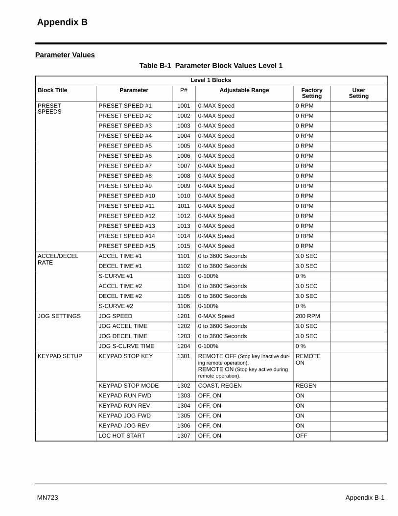
Appendix B
Appendix B-1MN723
Parameter Values
Table B-1 Parameter Block Values Level 1
Level 1 Blocks
Block Title Parameter P# Adjustable Range FactorySetting
UserSetting
PRESETSPEEDS
PRESET SPEED #1 1001 0-MAX Speed 0 RPMSPEEDS
PRESET SPEED #2 1002 0-MAX Speed 0 RPM
PRESET SPEED #3 1003 0-MAX Speed 0 RPM
PRESET SPEED #4 1004 0-MAX Speed 0 RPM
PRESET SPEED #5 1005 0-MAX Speed 0 RPM
PRESET SPEED #6 1006 0-MAX Speed 0 RPM
PRESET SPEED #7 1007 0-MAX Speed 0 RPM
PRESET SPEED #8 1008 0-MAX Speed 0 RPM
PRESET SPEED #9 1009 0-MAX Speed 0 RPM
PRESET SPEED #10 1010 0-MAX Speed 0 RPM
PRESET SPEED #11 1011 0-MAX Speed 0 RPM
PRESET SPEED #12 1012 0-MAX Speed 0 RPM
PRESET SPEED #13 1013 0-MAX Speed 0 RPM
PRESET SPEED #14 1014 0-MAX Speed 0 RPM
PRESET SPEED #15 1015 0-MAX Speed 0 RPM
ACCEL/DECELRATE
ACCEL TIME #1 1101 0 to 3600 Seconds 3.0 SECRATE
DECEL TIME #1 1102 0 to 3600 Seconds 3.0 SEC
S-CURVE #1 1103 0-100% 0 %
ACCEL TIME #2 1104 0 to 3600 Seconds 3.0 SEC
DECEL TIME #2 1105 0 to 3600 Seconds 3.0 SEC
S-CURVE #2 1106 0-100% 0 %
JOG SETTINGS JOG SPEED 1201 0-MAX Speed 200 RPM
JOG ACCEL TIME 1202 0 to 3600 Seconds 3.0 SEC
JOG DECEL TIME 1203 0 to 3600 Seconds 3.0 SEC
JOG S-CURVE TIME 1204 0-100% 0 %
KEYPAD SETUP KEYPAD STOP KEY 1301 REMOTE OFF (Stop key inactive dur-ing remote operation).REMOTE ON (Stop key active duringremote operation).
REMOTEON
KEYPAD STOP MODE 1302 COAST, REGEN REGEN
KEYPAD RUN FWD 1303 OFF, ON ON
KEYPAD RUN REV 1304 OFF, ON ON
KEYPAD JOG FWD 1305 OFF, ON ON
KEYPAD JOG REV 1306 OFF, ON ON
LOC HOT START 1307 OFF, ON OFF
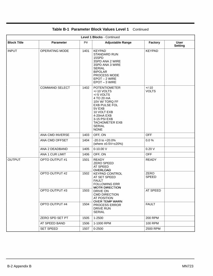
Section 1General Information
B-2 Appendix B MN723
Table B-1 Parameter Block Values Level 1 Continued
Level 1 Blocks - Continued
Block Title Parameter P# Adjustable Range Factory UserSetting
INPUT OPERATING MODE 1401 KEYPADSTANDARD RUN15SPD3SPD ANA 2 WIRE3SPD ANA 3 WIRESERIALBIPOLARPROCESS MODEEPOT – 2 WIREEPOT – 3 WIRE
KEYPAD
COMMAND SELECT 1402 POTENTIOMETER +/-10 VOLTS+/-5 VOLTS4 TO 20 mA10V W/ TORQ FFEXB PULSE FOL5V EXB10 VOLT EXB4-20mA EXB3-15 PSI EXBTACHOMETER EXBSERIALNONE
+/-10VOLTS
ANA CMD INVERSE 1403 OFF, ON OFF
ANA CMD OFFSET 1404 -20.0 to +20.0%(where ±0.5V=±20%)
0.0 %
ANA 2 DEADBAND 1405 0-10.00 V 0.20 V
ANA 1 CUR LIMIT 1406 OFF, ON OFF
OUTPUT OPTO OUTPUT #1 1501 READYZERO SPEED AT SPEEDOVERLOAD
READY
OPTO OUTPUT #2 1502OVERLOADKEYPAD CONTROLAT SET SPEEDFAULTFOLLOWING ERRMOTR DIRECTION
ZEROSPEED
OPTO OUTPUT #3 1503MOTR DIRECTIONDRIVE ONCMD DIRECTIONAT POSITIONOVER TEMP WARN
AT SPEED
OPTO OUTPUT #4 1504OVER TEMP WARNPROCESS ERRORDRIVE RUNSERIAL
FAULT
ZERO SPD SET PT 1505 1-2500 200 RPM
AT SPEED BAND 1506 1-1000 RPM 100 RPM
SET SPEED 1507 0-2500 2500 RPM

Section 1General Information
Appendix B-3MN723
Table B-1 Parameter Block Values Level 1 Continued
Level 1 Blocks - Continued
Block Title Parameter P# Adjustable Range Factory UserSetting
OUTPUT(Continued)
ANALOG OUT #1 1508 ABS SPEEDABS TORQUESPEED COMMANDPWM VOLTAGEFLUX CURRENTCMD FLUX CURLOAD CURRENTCMD LOAD CURMOTOR CURRENTLOAD COMPONENTQUAD VOLTAGEDIRECT VOLTAGE
C O G
ABSSPEED
ANALOG OUT #2 1509DIRECT VOLTAGEAC VOLTAGEBUS VOLTAGETORQUEPOWERVELOCITYOVERLOADPH2 CURRENTPH3 CURRENTPROCESS FDBKSETPOINT CMDPOSTIONSERIAL
MOTORCURRENT
ANALOG #1 SCALE 1510 10 - 100% 100%
ANALOG #2 SCALE 1511 10 - 100% 100%
POSITION BAND 1512 1-32767 CNTS 6 CNTS
BRUSHLESSCONTROL
RESOLVER ALIGN 1601 0.00–360.0 DEG CALCCONTROL
SPEED FILTER 1602 0–7 4
FEEDBACK ALIGN 1603 REVERSE, FORWARD FORWARD
CURRENT PROP GAIN 1604 0–1000 20
CURRENT INT GAIN 1605 0–400 150 HZ
SPEED PROP GAIN 1606 0–1000 10
SPEED INT GAIN 1607 0.00–9.99 1.00 HZ
SPEED DIFF GAIN 1608 0–100 0
POSITION GAIN 1609 0–9999 31
LEVEL 2 BLOCK ENTERS LEVEL 2 MENU - See Table B-2.
PRESS ENTER FOR
PROGRAMMING EXIT
Exit programming mode and return to display mode.
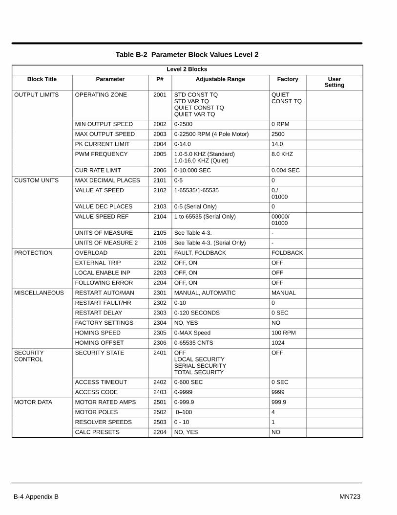
Section 1General Information
B-4 Appendix B MN723
Table B-2 Parameter Block Values Level 2
Level 2 Blocks
Block Title Parameter P# Adjustable Range Factory UserSetting
OUTPUT LIMITS OPERATING ZONE 2001 STD CONST TQSTD VAR TQQUIET CONST TQQUIET VAR TQ
QUIETCONST TQ
MIN OUTPUT SPEED 2002 0-2500 0 RPM
MAX OUTPUT SPEED 2003 0-22500 RPM (4 Pole Motor) 2500
PK CURRENT LIMIT 2004 0-14.0 14.0
PWM FREQUENCY 2005 1.0-5.0 KHZ (Standard)1.0-16.0 KHZ (Quiet)
8.0 KHZ
CUR RATE LIMIT 2006 0-10.000 SEC 0.004 SEC
CUSTOM UNITS MAX DECIMAL PLACES 2101 0-5 0
VALUE AT SPEED 2102 1-65535/1-65535 0./01000
VALUE DEC PLACES 2103 0-5 (Serial Only) 0
VALUE SPEED REF 2104 1 to 65535 (Serial Only) 00000/01000
UNITS OF MEASURE 2105 See Table 4-3. -
UNITS OF MEASURE 2 2106 See Table 4-3. (Serial Only) -
PROTECTION OVERLOAD 2201 FAULT, FOLDBACK FOLDBACK
EXTERNAL TRIP 2202 OFF, ON OFF
LOCAL ENABLE INP 2203 OFF, ON OFF
FOLLOWING ERROR 2204 OFF, ON OFF
MISCELLANEOUS RESTART AUTO/MAN 2301 MANUAL, AUTOMATIC MANUAL
RESTART FAULT/HR 2302 0-10 0
RESTART DELAY 2303 0-120 SECONDS 0 SEC
FACTORY SETTINGS 2304 NO, YES NO
HOMING SPEED 2305 0-MAX Speed 100 RPM
HOMING OFFSET 2306 0-65535 CNTS 1024
SECURITY CONTROL
SECURITY STATE 2401 OFFLOCAL SECURITYSERIAL SECURITYTOTAL SECURITY
OFF
ACCESS TIMEOUT 2402 0-600 SEC 0 SEC
ACCESS CODE 2403 0-9999 9999
MOTOR DATA MOTOR RATED AMPS 2501 0-999.9 999.9
MOTOR POLES 2502 0–100 4
RESOLVER SPEEDS 2503 0 - 10 1
CALC PRESETS 2204 NO, YES NO
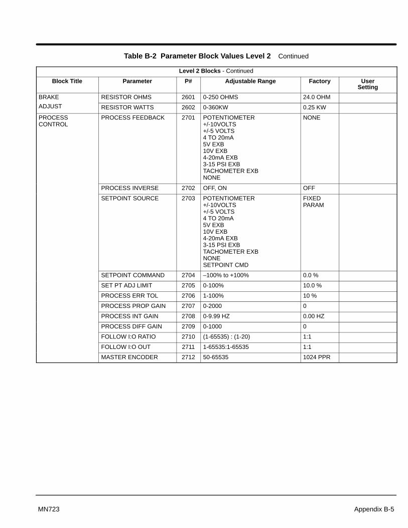
Section 1General Information
Appendix B-5MN723
Table B-2 Parameter Block Values Level 2 Continued
Level 2 Blocks - Continued
Block Title Parameter P# Adjustable Range Factory UserSetting
BRAKE RESISTOR OHMS 2601 0-250 OHMS 24.0 OHM
ADJUST RESISTOR WATTS 2602 0-360KW 0.25 KW
PROCESS CONTROL
PROCESS FEEDBACK 2701 POTENTIOMETER+/-10VOLTS+/-5 VOLTS4 TO 20mA5V EXB10V EXB4-20mA EXB3-15 PSI EXBTACHOMETER EXBNONE
NONE
PROCESS INVERSE 2702 OFF, ON OFF
SETPOINT SOURCE 2703 POTENTIOMETER+/-10VOLTS+/-5 VOLTS4 TO 20mA5V EXB10V EXB4-20mA EXB3-15 PSI EXBTACHOMETER EXBNONESETPOINT CMD
FIXEDPARAM
SETPOINT COMMAND 2704 –100% to +100% 0.0 %
SET PT ADJ LIMIT 2705 0-100% 10.0 %
PROCESS ERR TOL 2706 1-100% 10 %
PROCESS PROP GAIN 2707 0-2000 0
PROCESS INT GAIN 2708 0-9.99 HZ 0.00 HZ
PROCESS DIFF GAIN 2709 0-1000 0
FOLLOW I:O RATIO 2710 (1-65535) : (1-20) 1:1
FOLLOW I:O OUT 2711 1-65535:1-65535 1:1
MASTER ENCODER 2712 50-65535 1024 PPR
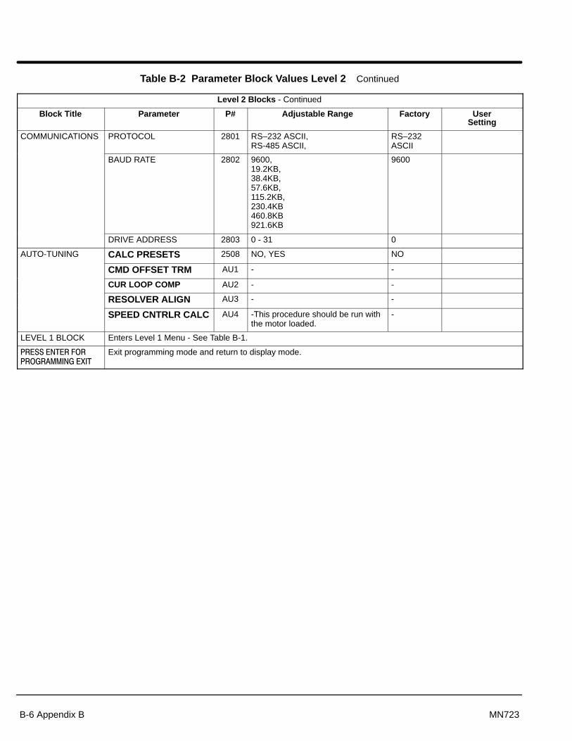
Section 1General Information
B-6 Appendix B MN723
Table B-2 Parameter Block Values Level 2 Continued
Level 2 Blocks - Continued
Block Title Parameter P# Adjustable Range Factory UserSetting
COMMUNICATIONS PROTOCOL 2801 RS–232 ASCII, RS-485 ASCII,
RS–232ASCII
BAUD RATE 2802 9600, 19.2KB, 38.4KB, 57.6KB, 115.2KB, 230.4KB 460.8KB921.6KB
9600
DRIVE ADDRESS 2803 0 - 31 0
AUTO-TUNING CALC PRESETS 2508 NO, YES NO
CMD OFFSET TRM AU1 - -
CUR LOOP COMP AU2 - -
RESOLVER ALIGN AU3 - -
SPEED CNTRLR CALC AU4 -This procedure should be run withthe motor loaded.
-
LEVEL 1 BLOCK Enters Level 1 Menu - See Table B-1.
PRESS ENTER FOR
PROGRAMMING EXIT
Exit programming mode and return to display mode.

Appendix C
Appendix C-1MN723
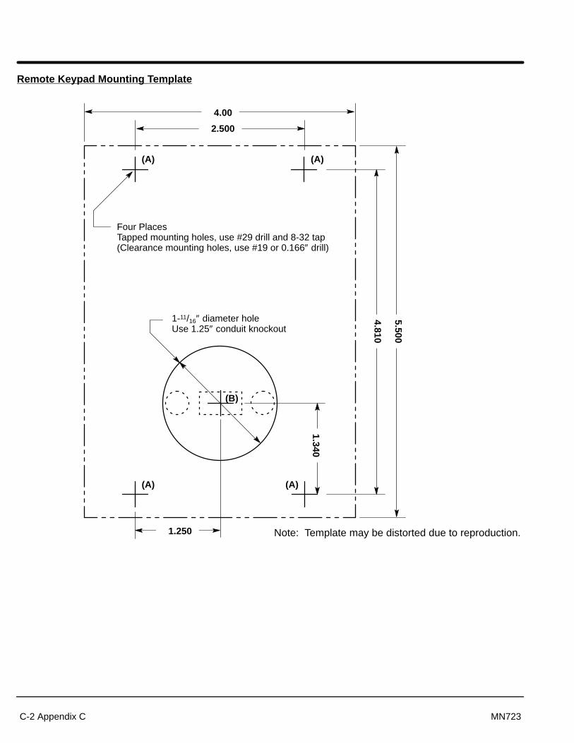
Section 1General Information
C-2 Appendix C MN723
Remote Keypad Mounting Template
Four PlacesTapped mounting holes, use #29 drill and 8-32 tap(Clearance mounting holes, use #19 or 0.166″ drill)
4.00
2.500
1.250
1.340
4.810
5.500
1-11/16″ diameter holeUse 1.25″ conduit knockout
(B)
(A) (A)
(A) (A)
Note: Template may be distorted due to reproduction.

BALDOR ELECTRIC COMPANYP.O. Box 2400
Ft. Smith, AR 72902–2400(501) 646–4711
Fax (501) 648–5792
Baldor Electric CompanyMN723
Printed in USA1/99 C&J 2500