ac servo school text ac servo practice course (melservo-j4) · 2016-01-28 · ac servo school text...
TRANSCRIPT
AC Servo School TextAC Servo Practice Course
(MELSERVO-J4)
AC Servo School Text AC Servo Practice Course (MELSERVO-J4)
AC Servo School TextAC Servo Practice Course (MELSERVO-J4)
Specifications subject to change without notice.
When exported from Japan, this manual does not require application to theMinistry of Economy, Trade and Industry for service transaction permission.
HEAD OFFICE : TOKYO BUILDING, 2-7-3 MARUNOUCHI, CHIYODA-KU, TOKYO 100-8310, JAPANNAGOYA WORKS : 1-14 , YADA-MINAMI 5-CHOME , HIGASHI-KU, NAGOYA , JAPAN
MODEL
MODELCODE
SH-030146ENG-A (1403) MEE

Safety Precautions
(Please read the precautions carefully before carrying out practical training.)
Read the relevant manuals and pay careful attention to safety when designing the system. When carrying out practical work, pay sufficient attention to the following points and handle the device properly.
[Practical training precautions]
! CAUTION
Follow the instructions of the instructor. Do not remove the training machine module or change the wiring without prior consent.
Doing so may cause failure, malfunction, injury, or fire. Turn the power supply OFF before removing or installing a module.
Removing or installing while the power is ON may cause module failure or electric shock.
If the training machine emits an abnormal odor or an abnormal sound, press the "Power switch" or "Emergency switch" to stop the device.
When an error occurs, contact the instructor immediately.
! WARNING
To avoid electric shock, do not touch the terminal while the power is on. When opening a safety cover, make sure that the power supply is disconnected or
ensure sufficient safety before carrying out the work.
Safety Precautions

― ― i
Table of Contents
1. AC Servo Fundamentals ········································································ 1-1
1.1 What is an AC Servo? ············································································ 1-1
1.2 AC Servo Positioning and Performance ····················································· 1-1
1.3 MELSERVO ··························································································· 1-6
1.3.1 Road Map of MELSERVO ·································································· 1-6
1.3.2 Product Lineup ················································································· 1-6
1.3.3 Comparison Table of General-Purpose Servo Amplifier Specifications ······· 1-7
1.3.4 Servo Motor Model Series and Features ·············································· 1-8
1.4 AC Servo Mechanism ·············································································· 1-9
1.4.1 Block Diagram of Servo Amplifier and Operating Principles ···················· 1-9
1.4.2 Characteristics of AC Servo Motor and Operating Principles ················· 1-14
1.4.3 Encoder Functions and Operating Principles ······································· 1-17
2. Positioning Control by AC Servo ····························································· 2-1
2.1 Positioning Method and Stopping Accuracy ················································ 2-1
2.1.1 Positioning Types ·············································································· 2-1
2.1.2 Positioning Control and Stopping Accuracy with the Speed Control Method ········ 2-1
2.1.3 Position Control Method Types ··························································· 2-4
2.2 Fundamentals of Positioning Control by AC Servo ······································ 2-5
2.2.1 Position Detection and Number of Pulses per Motor Rotation ················· 2-5
2.2.2 Position Servo Concepts ···································································· 2-5
2.3 Positioning Accuracy ················································································ 2-6
2.3.1 Machine Feed Length per Pulse ························································· 2-6
2.3.2 Overall Machine Accuracy and Electrical Side Accuracy ························· 2-7
2.4 Motor Speed for Machine Maximum Speed ················································ 2-8
2.5 Command Pulse ····················································································· 2-9
2.5.1 Electronic Gear Functions ·································································· 2-9
2.5.2 Maximum Input Pulse Frequency ······················································ 2-15
2.6 Speed Pattern and Stop Settling Time····················································· 2-16
2.6.1 Speed Pattern and Droop Pulse Behavior ·········································· 2-16
2.6.2 Stop Settling Time ts ····································································· 2-17
2.7 Relationship between Machine System and Response Level Setting ············ 2-18
2.7.1 Response Level Setting ··································································· 2-18
2.7.2 Real-Time Auto Tuning ···································································· 2-19

― ― ii
3. Positioning Controller ············································································· 3-1
3.1 Division of Servo Function and Positioning Controller ·································· 3-1
3.1.1 Positioning Controller Side Functions ··················································· 3-1
3.1.2 Servo Amplifier Side Functions ··························································· 3-1
3.2 Positioning Controller Classification and Configuration ·································· 3-1
3.3 Setting Data of Positioning Controller ························································ 3-5
3.3.1 Basic Parameters/Detailed Parameters ················································· 3-5
3.3.2 Home Position Return Basic Parameters/Home Position Return Detailed Parameters ···· 3-6
3.3.3 Positioning Data ················································································ 3-7
3.4 Position Command Interface ····································································· 3-9
3.5 Fundamentals of Positioning Control with the Positioning Controller ············· 3-11
3.5.1 Travel Direction of Machine and Rotation Direction of Servo Motor ······· 3-11
3.5.2 Types of Home Position Return ························································ 3-12
4. Functions and Operations of MELSERVO-J4 ··········································· 4-1
4.1 Function List ·························································································· 4-1
4.2 Configuration with Peripheral Equipment ····················································· 4-3
4.3 Operation after Installation ········································································ 4-5
4.3.1 Startup Procedure ············································································· 4-5
4.3.2 Installation ························································································ 4-6
4.3.3 Wiring System and Sequence ··························································· 4-14
4.3.4 Standard Connection Figure ····························································· 4-22
4.3.5 Power-On ······················································································· 4-38
4.3.6 Display/Diagnosis Function ······························································· 4-43
4.3.7 Parameters ····················································································· 4-55
4.3.8 Parameter Setting ··········································································· 4-77
4.3.9 External I/O Signals Check ······························································ 4-80
4.3.10 Test Operation of Position Control Mode ·········································· 4-82
4.3.11 Test Operation of Speed Control Mode ············································ 4-83
4.3.12 Test Operation of Torque Control Mode ··········································· 4-84
4.3.13 Test Operation Mode ····································································· 4-85
4.3.14 Useful Functions for Start-Up/Diagnostics ·········································· 4-89

― ― iii
5. Training Machine Operation ···································································· 5-1
5.1 Overview of AC Servo Training Device ······················································ 5-1
5.1.1 External Appearance/Configuration of Training Machine ·························· 5-1
5.1.2 Configuration of Input/Output Operation Panel ····································· 5-2
5.2 Practical Training of MR-J4 Servo Amplifier ················································ 5-3
5.2.1 Speed Control ·················································································· 5-3
5.2.2 Position Control ·············································································· 5-17
5.3 Operation Status Adjustment ·································································· 5-21
5.3.1 Adjustment of Servo Amplifier Unit ···················································· 5-21
5.3.2 One-Touch Tuning ············································································ 5-23
5.3.3 Auto Tuning ··················································································· 5-33
5.3.4 Manual Mode ················································································· 5-37
5.3.5 Adjustment Using MR Configurator2 ·················································· 5-41
5.4 Special Adjustment Function ··································································· 5-51
5.4.1 Filter Setting ··················································································· 5-51
5.4.1.1 Machine Resonance Suppression Filter ········································· 5-51
5.4.1.2 Adaptive Filter II ········································································ 5-54
5.4.1.3 Shaft Resonance Suppression Filter ············································· 5-56
5.4.1.4 Low-Pass Filter ·········································································· 5-57
5.4.1.5 Advanced Vibration Suppression Control II ···································· 5-57
5.4.1.6 Command Notch Filter ································································ 5-61
5.4.2 Gain Switching Function ··································································· 5-63
5.4.2.1 Application ················································································ 5-63
5.4.2.2 Function Block Diagram ······························································ 5-64
5.4.2.3 Parameters ··············································································· 5-65
5.4.2.4 Gain Switching Procedure ··························································· 5-67
5.4.3 Tough Drive Function ······································································ 5-70
5.4.3.1 Vibration Tough Drive Function ···················································· 5-70
5.4.3.2 Instantaneous Power Failure Tough Drive ····································· 5-72
5.4.4 Connection of Laboratory Device ······················································· 5-74

― ― iv
6. Selection ······························································································· 6-1
6.1 Temporary Selection of Motor Capacity ···················································· 6-1
6.1.1 Load Moment of Inertia JL ································································· 6-1
6.1.2 Load Torque TL ················································································ 6-1
6.1.3 Load Moment of Inertia/Load Torque Calculation Formula ······················· 6-2
6.2 Reduction Ratio ······················································································ 6-4
6.3 Operation Pattern and Motor Required Torque············································ 6-5
6.3.1 Acceleration Torque Ta ······································································ 6-5
6.3.2 Deceleration Torque Td ····································································· 6-5
6.3.3 Operation Pattern ·············································································· 6-6
6.3.4 Determining Motor Capacity ································································ 6-7
6.3.5 Capacity Selection Flow and Calculation ·············································· 6-8
6.3.6 Calculation Example ········································································ 6-12
6.4 Capacity Selection Software ··································································· 6-20
7. Noise Reduction Techniques, Leakage Current, Harmonics ························· 7-1
7.1 Noise Reduction Techniques ···································································· 7-1
7.2 Leakage Current ····················································································· 7-3
7.3 Harmonics ······························································································ 7-5
7.3.1 Fundamental Harmonic and Harmonics ················································ 7-5
7.3.2 Characteristics of Rectification Circuits and Harmonic Occurrence············ 7-6
7.3.3 Harmonics Countermeasures ······························································· 7-7
8. Maintenance and Inspection ··································································· 8-1
8.1 Precautions for Maintenance and Inspection ··············································· 8-1
8.2 Check Items ··························································································· 8-1
8.3 Part Replacement ··················································································· 8-4
8.4 Troubleshooting ······················································································ 8-5
8.4.1 Alarm/Warning List ············································································ 8-6
8.4.2 Alarm Corrective Action ····································································· 8-11
8.4.3 Warning Corrective Action ·································································· 8-12
Appendix
Appendix 1. Various Symbols ······························································ Appendix-1
Appendix 2. Drive System Types ························································· Appendix-2
Appendix 3. Positioning Controller ························································ Appendix-6
Appendix 4. Terminology ·································································· Appendix-12
Appendix 5. Protection Model of Motor ·············································· Appendix-21
Appendix 6. QD75D1N Setting Values (Training Machine) ···················· Appendix-23

― ― v
Memo

1. AC Servo Fundament als
1-1
1.1 What is an AC Servo? Generally define as "a contro l system wherein position, di rection, and orientation of the object are considered as controlled variables and it is configured in such a w ay that it conforms to changes in any set values", a servo mechanism detects the present va lue (position, speed, etc.) if a set value (position, s peed, etc.) is input to the servo mechanism by a command part, compares the target value w ith the set val ue, and performs cont rol so that the difference is always minimized.
Setting Commandpart
Controlpart
Maincircuit
part
Servo amplifier
Servomotor
Detector(Encoder)
Moving part
Servo mechanism
1.2 AC Servo Positioning and Performance Compared to regular motors, a servo motor is specifically designed with consideration for the moment of inertia of the rotor (also called J or GD2) and the electrical responses in such a way that it can respond to sudden alterations of voltage and current from the servo amplifier. In addition, even the servo amplif ier that drives t he servomotor is configured so that the s peed and position control commands can be precisely and quickly transmitted to the servo motor. In this w ay, this section compares the differences between the ty pical characteristics for using the servomotor (integrated motor combined with a servo amplifier) with those of a motor driven by a general-purpose inverter used a general variable speed device. (1) Comparison of features of general-purpose servo
and various types of controlling devices Speed-torque characteristics constitute a general method for indicating motor characteristics. Figure 1.2 shows a comparison of the characteristics of a servo motor and a general-purpose motor that uses general-purpose inverter. As shown in this figure, the following three points can be considered features of the servo motor. 1) Speed control range is wide 2) Torque characteristics are fixed with high-
speed operation and low-speed operation 3) Maximum torque is high
Note: As the maximum torque is high and the moment of inertia is low, rapid acceleration/deceleration is possible.
Max servo torque characteristics
Torque difference in servo and inverter
MR servo
(Short-duration running range)
Max. inverter torquecharacteristics
Torq
ue(%
)
Rating
Continuous runningcharacteristic of servoContinuous running
characteristic of inverterRotation speed (rated)
Figure 1.1 Configuration di agram of servo mechanism
The elements that make up the servo mechanism are called the servo elements, and these consist of a drive amplifier (AC servo amplifier), a drive motor (AC servo motor), and a detector. Figure 1.1 shows a configuration example.
Figure 1.2 Comparison of tor que characteristics of servo and inverter

1. AC Servo Fundamentals
1-2
Table 1.1 Main performance of servo motor
Item Specifications Description
Speed control range
1:1000 to 5000
(1:10) Use is possible without concern for the rotation stability or the torque dropping until 1/1000th of the rated speed.
Torque characteristics
No decline in torque during low-speed
operation
A fixed output torque can be obtained in an area of the speed control range for both the continuous operation torque and maximum torque.
Accordingly, use is safe throughout the entire speed area even with a constant-torque load.
Maximum torque Approximately 300%
(150%)
Approximately 300% of the rated torque can be obtained for instant maximum torque.
Accordingly, use is possible for high-frequency positioning because of compatibility with rapid acceleration/deceleration.
Note: The numerical value within ( ) in the specifications column indicates general specifications of a general-purpose inverter.
(2) AC servo applications The servo motor features are as described in the previous item, but there is also a positioning function for functions that do not exist in other variable speed devices when combined with a servo amplifier. Although the positioning function details have been mentioned in Chapter 2, this section explains the typical applications of the servo motor, from the positioning function characteristics to the servo and the features described in (1) in the previous section.
1) Machines that require positioning If an AC servo is used combined with a specialized positioning controller, it is possible to perform high-accuracy positioning. With a general Mitsubishi AC servo, positioning of 4000 to 4194304 divisions is possible in the motor axis, and this can be sufficiently applied for 1 μm positioning in 24 m/minute to 8 m/minute machines.
Application examples: Machine tool devices, wood-working machines, transportation machines, packaging machines, inserters/mounters, individual types of feeders, individual types of cutters, specialized machines
(a) X-Y Table Connects the respective ball screw loads to the X axis and Y axis, and allows high-speed, high-accuracy positioning by the biaxial AC servo.
(b) Transportation machine (vertical) Carries out the transportation positioning of the lifter. A servo motor with an electromagnetic brake is used to prevent droppage during a power failure.
Lifter
Automated storage/picking system Even with automated storage, the AC servo is often used in picking/traveling sections in accordance with the high-speed conversion needs. By using an AC servo motor, smooth and accelerated speed can be implemented quickly. Automated storage/picking systems connected to the SCM (Supply chain management) deliver significant improvements to the stock management efficiency of commodity distribution from the procurement of raw materials to the delivery of goods.
Conveyor
Stackercrane
[ ]

1. AC Servo Fundamentals
1-3
(c) Synchronized feeding (coating line)
Detects the position of the product by sensors and carries out synchronized feeding according to encoder signals. Returns to the home position after sending a predetermined distance and waits for arrival of the next product.
Synchronizing encoder
Positioning module
Sen
sor
(d) Press roll feeder Drives a feed roll using an AC servo motor and supplies material only for a fixed length. Material is supplied to the press when the press head is elevated, and after positioning is complete, punching is carried out.
Press body
Roll feeder
Servo motor
2) Machines that require a wide transmission range Because the AC servo has characteristics that do not exist in other variable speed motors, including highly accurate speed control performance with a speed control range of 1:1000 to 1:5000, speed variation of 0.01% or less, and a fixed output torque, AC servo motors are used for highly accurate variable speed drives that start with varied line controlling.
Application examples: Various axes of printing machines, paper-making machines, film manufacturing lines, wire drawing machines, coil winding machines, various specialized machine feeding, various transportation machines, winders/rollers, and woodworking machines
(a) Spin coating Uses the principles of the following illustration for making semiconductor circuits. A spin coater applies a photosensitizing agent (photoresist) to a semiconductor wafer. The principle is drop the resist liquid and spread it out thinly through centrifugal force. If the rotation speed of the wafer is too fast, the resist will fly off, and conversely, if it is too slow, the resist will not be applied evenly.
Wafer Photoresist
Ro
tatio
n
[ ]

1. AC Servo Fundamentals
1-4
3) High-frequency positioning Although positioning is carried out as described in (1), the AC servo has a maximum torque approximately 300% of the rated torque, and with motor units, it can achieve several 10 ms steep accelerations/decelerations from stopped to the rated speed and can even correspond to high-frequency positioning of 100 times or more in 1 minute. Compared with other positioning methods (clutch brake, DC motor, etc.), using an AC servo offers significant features including no mechanical areas of contact for maintenance-free operation and less effects due to ambient temperatures.
Application examples: Press feeders, bag-making machines, sheet cutting, loaders/unloaders, filling machines, packaging machines, various transportation machines, mounters, bonders
(a) Mounter and base inspection
Check whether the electronic components (LSI, resistor, capacitor, etc.)are mounted on the printed-circuit board. Positioning accuracy and highspeed performance are requested.
Check whether the electronic components (LSI, resistor, capacitor, etc.)are mounted correctly on the printed-circuit board. In some cases, theboard itself is also checked.
Mounter Base inspection
Camera
(b) Wafer probers
Because it is possible to have many LSI chips from one wafer, inspection is done before assembly with a wafer prober and tester in chip units. Accurate positioning is necessary for setting the point in the chip. High speeds are also requested.
Test headProber needle
point
WaferWafer prober
Wafer stage Test in chipunits
Wafer
(c) Filling machine lines and packaging machine lines
Filling machine line Bottles capable of large amounts arefilled with different volumes of liquid at fast speeds. The fillingspeed can be controlled according to the shape of the bottlesso that the liquid does not bubble over the specified value.
Servo motors are used to pack foodstuff in film properly andhygienically. The point is to cut and separate the rolled film intoprecise sizes after the packaging is done according to the sizeof food products.
Filling machine line
Nozzle up/down
Filling
Packaging machine line
Load productFilm roll
Packaging moldHeat sealing roller
Sealing/cutting
Film
Conveyor
ConveyorUnload product
[ ]

1. AC Servo Fundamentals
1-5
4) Torque control
In addition to the speed control and position control functions, there is also a function by which torque control is possible, which allows application even in tension control areas such as various winding/rolling devices.
(a) Slitters and laminators
The laminator is used to superimpose and fuse several films. It isimportant to control the tension and adjust the right amount of pressureso that superimposing is done well. The same mechanism is also usedin coating machines, printers, etc.
A slitting machine is used for slitting at the winded part asthe final process after processing has been performed inthe processing part. The point is to slit successfully usingthe slitter by controlling the tension.
Slitter Laminator
Cutter
(b) Winding devices Carries out winding tension control of sheet material by combining an AC servo and a tension detector/tension controller device.
Detector
Servo amplifier
Tens
ion
cont
rolle
r
Torquecommand
input
(c) Mold injection machines
Injects plastic raw material pellets of molded articles into the molding part. The pellets are melted by the heater provided in the part consisting of the cylinder and the screw axis. After that, the mold is opened through a cooling operation and the molded component is extruded by an ejector pin. Items exceeding 3,000 t also exist in applications with large components and large clamping forces.
Molded itemPellet Hopper
Screwdrive
Injectiondrive
Moldclamping
drive
Ejectordrive
Heater
Cylinder
Mold (moving side) Mold (fixed side)

1. AC Servo Fundamentals
1-6
1.3 MELSERVO
1.3.1 Road Map of MELSERVO
After the release of a general-purpose AC servo in 1982, new products have always incorporated new technology reflecting innovation and items requested by the industry. Now, the environment surrounding servos is now transitioning into the next generation. The MR-J4 Series is developed in response to requests for even faster speeds, higher accuracy, start-up time reduction, and enhanced diagnostics and maintenance in order to achieve the best performance of a machine. The following table shows the MELSERVO road map.
Networking Diagnosis function
Better productivity (per hour/per area)Wider range of servo applications
Fastest (current) "MR-J2-Super Series" released
MR-H
Most compact (at present)
Easy startup
Conformance to standardsEnvironmental resistanceHigh-speed,high-performance
CompactLow noisePower savingwiring
Maintenance-freeHigh-speedresponse, CM
Low cost
Better productivityDemands
of theindustry
Company's first servo amplifier released
First-of-its-kind, all-digital servoreleased
One-touchservo released
MR-JN
Serv
oam
plif
ie
Top-of-the-lineequipment (at present)
Integrated 2-axis type
Ultra-compact series released
1.3.2 Product Lineup
The following table shows the MELSERVO Series line up.
Motor capacity range *Indicates the corresponding servo motor capacity range.
MR-J4 Series200 V/400 V AC specifications
MR-J4W multi axis200 V AC specificationsIntegrated 2-axis/3-axis
MR-J3 Series200 V/400 V AC specifications
MR-J3 Series48 V/24 V DC specifications200 V AC specificationsIntegrated 2-axis
MR-JN Series200 V AC specifications

1. AC Servo Fundamentals
1-7
1.3.3 Comparison Table of General-Purpose Servo Amplifier Specifications
Model Item
MR-J4- Series MR-J3- Series MR-JN- Series
Appearance
Features
Increased performance and functionality over MELSERVO_J3 Series
High-resolution, industry-leading level servo motor
MR Configurator2 (SW1DNC-MRC2-E)
High-speed, SSCNET III/H-compliant optical communication
High-performance type High-resolution servo
motor MR Configurator2
(SW1DNC-MRC2-E) Low rigidity due to
vibration suppression control Improved vibration suppression for the machine
One-touch servo MR Configurator2
(SW1DNC-MRC2-E) One-touch tuning/real-
time auto tuning, equipped with a tough drive function
Applicable motor capacity
0.05 kW to 22 kW 0.05 kW to 55 kW 0.05 kW to 0.4 kW
Brake/Reducer Exists Exists Exists
Encoder signal Serial communication Serial communication Serial communication
Position resolution 4194304 p/rev 262144 p/rev 131072 p/rev
Detection method INC/ABS INC/ABS INC
Rotation speed
(r/min)
Rated speed 3000 3000 3000
Maximum speed
6000 6000 4500
Maximum torque % (Rated torque % ratio) 350%
*1 350%
*2 300%
Control mode Position/Speed/Torque Position/Speed/Torque Position/Speed/Torque
Frequency response level
2.5 kHz 2.1 kHz -
Control theory Sine-wave PWM
control/current control Sine-wave PWM
control/current control Sine-wave PWM
control/current control One-touch tuning Exists Does not exist Exists
Auto tuning Real-time Real-time Real-time
Personal computer I/F Standard equipment Standard equipment Standard equipment
Speed control range 1:5000 1:5000 1:5000
External power supply for I/F
24 V DC required 24 V DC required 24 V DC required
Regenerative brake resistance
Built-in Built-in Built-in
Dynamic brake Built-in Built-in Built-in
Display (main body) 5-digit display (alarm 3-
digit conversion) 5-digit display 3-digit display
Setting key, etc. 4 setting buttons 4 setting buttons 4 setting buttons
Analog monitor 2 CH 2 CH Does not exist
Pulse frequency dividing output
Phases A, B, and Z Phases A, B, and Z Phases A, B, and Z
Test mode operation Available Available Available
Motor-less operation Available Available Available
EN compatibility Obtained Obtained Obtained
UL/cUL standard compatibility
Obtained Obtained Obtained
Supported motors
HG-KR Series HG-MR Series HG-SR Series
HF-KP Series HF-MP Series HF-SP Series HC-RP Series HC-UP Series
HC-KN Series
*1: HG-KR Series servo motor only *2: HF-KP Series servo motor only

1. AC Servo Fundamentals
1-8
1.3.4 Servo Motor Model Series and Features
With the AC servo MELSERVO-J4, J3, JN Series, various motors are offered according to machine requirements. MELSERVO-J4 Series: ABS, 22-bit (4194304-pulse) encoder MELSERVO-J3 Series: ABS, 18-bit (262144-pulse) encoder MELSERVO-JN Series: INC, 17-bit (131072-pulse) encoder
Series Capacity
(W)
Encoder resolutionpulse/rev
Encodercompat-
ibility Rated speed
Applicable servo
amplifier model
Pro- tection model
Application
Ultr
a-lo
w in
ertia
, sm
all c
apac
ity
HG-MR50 W to 750 W
4194304ABS/INCshared
3000 r/min MR-J4 IP65
Inserter, mounter, bonder
Printed circuit board punching machines
In-circuit testers Label-printing
machines Knitting machines,
embroidery machines
Ultra-compact robots
Robot tips etc.
HF-MP50 W to 750 W
262144ABS/INCshared
3000 r/min MR-J3 IP65
Low
iner
tia,
smal
l ca
pa
city
HG-KR50 W to 750 W
4194304ABS/INCshared
3000 r/min MR-J4 IP65
HF-KP50 W to 750 W
262144ABS/INCshared
3000 r/min MR-J3 IP65
HF-KN50 W to 400 W
131072 INC 3000 r/min MR-JN IP65
Med
ium
iner
tia,
med
ium
ca
pa
city
HG-SR0.5 kW -7.0 kW
4194304ABS/INCshared
1500 r/min 3000 r/min
MR-J4 IP67
Transportation machines
Specialized machines
Robots, turrets Loaders, unloaders Winders, tension
devices X-Y tables Test machines
etc.
HF-SP0.5 kW -7.0 kW
262144ABS/INCshared
1000 r/min 2000 r/min
MR-J3 IP67
Low
iner
tia,
med
ium
cap
acity
HC-LP0.5 kW -3 kW
262144ABS/INCshared
2000 r/min MR-J3 IP67
Roll feeders Loaders, unloaders High-throughput
material handling systems
etc.
Fla
t ty
pe
HC-UP0.75 kW -5 kW
262144ABS/INCshared
2000 r/min MR-J3 IP65
Robots Transportation
machines Food-processing
machines Winders, tension
devices etc.
Larg
e ca
paci
ty
400V
HF-JP0.5 kW -15 kW
262144ABS/INCshared
1500 r/min to
3000 r/min MR-J3 IP65
Mold injection machines
Semiconductor manufacturing systems
Large transportation machines
etc.
HA-LP 5 kW
-55 kW 262144
ABS/INCshared
1000 r/min to
2000 r/min MR-J3 IP44
Low
iner
tia,
larg
e ca
pa
city
HG-JR
11 kW -22 kW
4194304ABS/INCshared
1500 r/min MR-J4 IP67/IP44
Food-packaging machines
Printing machines Injection molding
machine press machines
etc.
Low
iner
tia,
med
ium
ca
paci
ty
0.5 kW -9 kW
4194304ABS/INCshared
3000 r/min MR-J4 IP67

1. AC Servo Fundamentals
1-9
1.4 AC Servo Mechanism
1.4.1 Block Diagram of Servo Amplifier and Operating Principles
The following block diagram shows the basic functions and operating principles of the servo amplifier.
Main circuitpart
Power supplyThree-phase AC200 V, 50 Hz200 to 230 V50/60 Hz
Control circuitportion
Position controlblock diagram
Position commandinput pulse
External torque(control command
(0~10 V)
External torquelimit
Servo amplifier Regenerative option Servo motor
Converter Capacitor Regenerative brake Inverter Dynamic brake
(No MR-C)
Acc
eler
atio
n/de
cele
ratio
ntim
eco
nsta
nt
Ele
ctro
nic
gea
r
Co
unt
er
Pos
itio
ng
ain
Spe
ed
gai
n
Cla
mp
Cur
rent
limit
PW
M
A/D conversion
Position feedback
Speed feedback
Internal torquelimit
Switch monitor
Inte
rfac
e
Det
ecto
r
Analog monitor(Speed or torque etc)
Current feedback
Figure 1.3 AC servo block diagram (pulse train method)

1. AC Servo Fundamentals
1-10
(1) Main circuit portion The basic functions of the main circuit portion include commutating/smoothing AC power (three-phase 200 to 230 V AC, 50/60 Hz) using a converter (diode bridge, capacitor), supplying a three-phase current of any voltage/frequency controlled by a sine-wave PWM from the inverter (IGBT) to the motor, and controlling the speed and torque of the motor. 1) Converter, smoothing capacitor
AC power is commutated using a diode bridge, and a DC power supply with fewer ripples is created using a smoothing capacitor.
AC power Converter output Capacitor
Vol
tage
Vol
tage
Vol
tage
Figure 1.4 External voltage of servo amplifier
2) Inverter
An inverter creates a current of an amplitude that balances with the frequency and load torque corresponding to the rotation speed of the motor from the DC power supply created by the converter and smoothing capacitor, and supplies it to the motor.
Inverter partThree-phase AC
Motor
Composite current
Switching currentSee Figure 1.9.
Figure 1.5 Configuration of inverter portion Figure 1.6 Output current of inverter

1. AC Servo Fundamentals
1-11
As shown in Figure 1.7, the rotation direction and rotation speed (frequency) of the motor are controlled by the direction of the current and the current-carrying width by switching the transistor in the inverter-portion on/off. The amplitude of the current is controlled by the energizing width. This method is called PWM control (pulse width control).
(a) When current is low (b) When current is high
Composite current
Figure 1.7 Current control according to PWM
3) Regenerative brake
1. Regenerative brake circuit The regenerative brake is operated when the actual rotation speed of the motor becomes higher than the command speed, such as during deceleration, dropping of the vertical axis, or when braking is applied to the winding axis, and braking force is obtained by absorbing (consuming) the energy through a regenerative resistor built in to the servo amplifier side for the rotation energy contained in the motor and the load. Such an operating status is called regenerative operation, and a regenerative circuit is provided in normal servo amplifiers. In this case, because the regenerative circuit is operated as a load on the motor, the regenerative braking force differs according to the energy consumption ratio of the circuit, and the amount of regenerative energy is influenced by the operating conditions. When it is necessary to consume a large amount of regenerative energy, it is possible to do so by providing a circuit outside of the servo amplifier.
2. Types of regenerative brake circuit For small capacity and low regenerative energy, energy is temporarily charged in the
aforementioned smoothing capacitor. This is called the capacitor regeneration method and is used for 0.4 kW or lower.
For medium capacity, the current flows to the resistor and a method where energy is consumed as heat is adopted. This is called the resistance regeneration method, and if the amount of regenerative energy becomes large, the resistor expands, which may result in problems including influence from the generation of ambient heat.
For large capacity, in order to cover the disadvantages of the abovementioned resistance regeneration method, methods carried out by returning the regenerative energy to the power supply side are also recently being adopted. This is called the power supply regeneration method and is used for 11 kW or more.
4) Dynamic brakes
When stopped (base circuit shut-off) due to the output of the inverter portion when the power turns off or when an alarm occurs, the motor will be free-running and a longer period will be required until stopping, which increases the coasting distance and can result in defects such as collision at the stroke end.

1. AC Servo Fundamentals
1-12
Dynamic braking is a function that causes a short-circuit between the terminals of the servo motor through an appropriate resistor when there is a base circuit shut-off, and then heat consumption is performed for rotational energy, which causes an immediate stop. Although dynamic braking is built in to conventional amplifiers, some servo amplifier models like the 11 kW of MR-J3 type or higher have a separately installation. The retaining force at the time of stopping does not exist for dynamic braking, so it is necessary to retain the force by mechanical braking simultaneously with braking for vertical feeding cases.
Even when a command pulse is input by the position control portion, the motor is operated with a certain degree of delay from the command. As such, a pulse equivalent to the delay is retained in the deviation counter. This is called a droop pulse. This droop pulse is output in the speed control portion as a speed command.
Mot
orsp
eed
Coastingdistance
Dynamic brake
Coast
Commandpulse train
Deviationcounter
(Pulse droop)
Speed commandControl part
Feedback pulses(Encoder)
Spe
ed
Command speed (pulse frequency)
Pulse droop
Motor speed
Pul
sedr
oop When the speed is constant, the pulse droop is also constant.
(2) Control circuit portion Using a micro computer, the control amounts (position, speed, current) from the command values (setvalues) and current values are subjected to operation processing at high speeds and high accuracy incombination with implementation of high-accuracy, fast-response servo control, and the monitor and module control content is protected. The following section offers a control description summary. 1) Position control
Motor rotation speed/direction control and high accuracy positioning are executed by a pulse train.
(Droop pulse)
Droop pulse
When the speed is constant, the droop pulse is also constant.
Dro
op p
ulse

1. AC Servo Fundamentals
1-13
2) Speed control The output of the position control portion deviation counter is proportional to the command speed, and this results in a speed command. The speed command portion outputs the speed command and motor speed deviation as a current command. When operated in speed control mode, the control signals and analogue voltage (0 to ±10 V) are input from external parts as a speed command.
3) Current control/three-phase generation circuit The current control portion controls the motor current so that the motor is operated according to the position command or the speed command by controlling the main circuit inverter. As such, the phase of the three-phase alternate current that conforms to the motor field (decided by the position of the permanent magnet of the rotor) is determined, and a current corresponding to the speed deviation is applied.
Main circuit device (IGBT) Servo motor
MagnetThree-phase coil
(Armature)
RotorPermanent magnet
(Field)
PWMgeneration
circuit
Three-phasecurrent command (Encoder)
Speed control
Speeddeviation
Multiplier
Currentcontrol
Standard three-phase Currentfeedback
Magnetic polepositiondetection
Three-phasegeneration
circuit
PLC magneticpole position
detection
Phase U
Phase V
Phase W
Magnetic pole position detection Standard three-phaseThree-phase currentcommand
Speeddeviation
Phase U
Phase V
Phase W
Figure 1.8 Principles of current control

1. AC Servo Fundamentals
1-14
With synchronous electric motors, it is necessary for the motor current to match the phase with the field position (magnetic pole position). This is why the motor detector has the signals that detect the magnetic pole position, and normally there is feedback of that position to the servo amplifier. The servo amplifier creates a reference three-phase current with the three-phase occurrence circuit portion based on those signals. The current control portion sets the speed deviation in the reference three-phase current, creates a three-phase current command, and controls the PWM circuit. Note: Independent fields do not exist in induction servo motors. Accordingly, magnetic pole position detection is not necessary. The PWM method is the method that generates the switching pulse several times in one cycle, and changes that pulse width to change the output voltage. The number of switching pulses generated in 1 second is called the carrier frequency. With the PWM method, motor vibrations and undesired motor sounds of frequency components proportional to the carrier frequency will occur.
Current command(Single phase part)
Modulation wave(Carrier, approx. 9 kHz)
Figure 1.9 Principles of PWM control
1.4.2 Characteristics of AC Servo Motor and Operating Principles
(1) Characteristics The output torque of the servo motor is proportional to the current that flows in the motor.Because the servo amplifier normally detects the motor speed and controls in such a way that the current flow in response to speed deviations, the servo motor can operate from a low speed to a high speed with a fixed torque. The figure on the right shows the torque characteristics of a servo motor and servo amplifier combination.
Torq
ue
(%)
Short-durationrunning range
Maximumtorque
Rated torqueContinuous
running range
Rated speed
Figure 1.10 Torque characteristics of servo motor
Rated speed [r/min]

1. AC Servo Fundamentals
1-15
(2) Operating principles The operating principles of every small and large motor are the same with torque occurring according to Fleming's left-hand rule, which states that if a current flows through a conductor in a magnetic field, a force acts in the conductor. For SM-type (synchronous type) AC servo motors, a permanent magnet is provided in the rotor, a coil through which a current flows is provided in the magnet, and current that corresponds to the rotor operation (rotation speed/direction, output torque) flows through the magnet coil.
Principles of motor torque generation
Operating principles of SM-type AC servo motors A current flows through the coil that bisects the magnetic flux from the rotor magnet by turning the amplifier transistor ON/OFF. The applied voltage is subjected to switching by several kHz, and the flowing current is smoothened by reactance of the winding wire and forms a sine-wave. The + - interval of the coil voltage is determined by the magnetic pole position detection signal from the detector directly connected to the motor shaft, and no phenomenon of loss in synchronism such as with a normally synchronous motor does not exist because it is normally controlled in such a way that the magnetic flux and the current bisect.
Figure 1.11 Cross-section of SM-type AC servo motor
Power Magnetic flux
Counteractive
Force onconductor
[Flemming's left-hand rule]
Cur
rent
Magnetic flux
Current
Current
Coi
l
MagnetCoil
Permanentmagnet(Rotor)

1. AC Servo Fundamentals
1-16
(3) Principles of IM type (induced current electrical motor) motor (vector control inverter) Even for induced current electric motors, the principles of the occurrence of torque are the same as for synchronous electric motors. However, there is no permanent magnet on the rotor side, as can be seen in the cross-sectional figure shown in the figure on the right, and it is not possible to supply the current Ia and the magnetic flux Φ individually. Accordingly, the current flows through the coil, and torque occurs due to the current that flows in the rotor groove by the electromagnetic induction action and by the magnetic flux created by the motor coil current. In this way, both the torque current and the magnetic flux current flow through the magnet coil, and this relationship is shown in formula (1-1).
Figure 1.12 Cross-section of IM-type motor I1 = Ia + I b (1-1)
I1: Magnet coil current; Ia: Torque current; Ib: Magnetic flux electric current Note: The above formula is a vector summation, not an arithmetic summation.
In other words, it is necessary to control the two currents individually in IM-type motors. This is called vector control. IM-type motors have the same torque characteristics as servo motors using vector control.
(4) Servo motor types and features An AC servo and a DC servo exist in the servo motor, and the AC servo is further divided into SM types (synchronous electric motors) and IM types (induced current electric motors). Table 1.2 shows the structure and characteristics of each servo motor.
Table 1.2
Type Structure Characteristics
Pros Cons
SM-type AC servo motor
Encoder
Rotor(Permanent
magnet) MagnetFrame
Bearing
Shaft
Maintenance-free Excellent environmental
resistance Capable of large torque Power generation braking is
possible at time of power failure
Compact, lightweight High power rate
Servo amplifier is somewhat more complicated than that for a DC motor
Correspondence of 1:1 motor and servo amplifier necessary
Risk of magnet demagnetization
IM-type motor
Cage rotorMagnetEncoder Frame
Bearing
Shaft
Maintenance-free Excellent environmental
resistance Capable of high speeds and
large torque Good efficiency in a large
capacity Robust structure
Servo amplifier is somewhat more complicated than that for a DC motor
Braking is not possible with a power failure
Characteristics change according to temperature
Correspondence of 1:1 motor and servo amplifier necessary
DC-type servo motor
BrushCommutator Rotor
Magnet(Permanent magnet)
Encoder Frame
Bearing
Shaft
Configuration of the servo amplifier is simple
Power generation braking is possible with a power failure
Low cost with a small capacity High power rate
Maintenance and periodic inspection around the commutator is necessary
Generation of brush abrasion powder; difficult to use in clean places
Cannot be used with high-speed large torque in relation to a commutating brush
Risk of magnet demagnetization
[ ]
MagnetCoil
Rotor groove(AI diecast)

1. AC Servo Fundamentals
1-17
Although the servo motor has been developed from an easily controllable DC servo motor, the complicated control resulting from the development of electronic devices substituted in the micro processor is high-speed, and with the transition to an AC servo motor that is maintenance-free and has good production characteristics with the possibility of being produced at a low cost, applications of 50 W or more are currently substituted with an SM-type AC servo. Furthermore, an IM-type motor has a robust structure and is easily applicable to large-form and high-speed conversions, and a larger capacity also results in improved efficiency. For this reason, this type is mainly used in cases requiring 7.5 kW or more, and with higher accuracy of large-form line control, their use has widened into areas where DC motors were the norm. Recently, however, vector control inverters are being changed to IM-type motors.
Figure 1.13 Transition of servo motor
1.4.3 Encoder Functions and Operating Principles
As explained above, in servo control, the feedback of the actual value for the command value (motor speed, position) is taken and is controlled so that deviation is reduced. Accordingly, the detector is an indispensable element of the servo system. (1) Encoder structure
The following figure shows the structure of the encoder mainly used as the detector.
Optical
Axis of rotation
Rotating glass disk
Light shieldingmask is printed
Auto sensor Slit
Create signal A, B,Z with phase shifting
Figure 1.14 Encoder structure
0.01
0.1
1
•11
Cap
acity
(kW
)
1980 (S55)
1985 (S60)
1990 (H2)
1995 (H7)
2000 (H12)
DC-type servo motor
SM-type AC servo motor
IM-type motor •55
•22
2012 (H24)
1. AC Servo Fundamentals
1-18
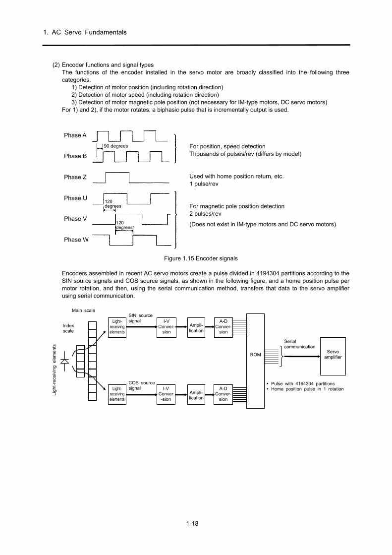
(2) Encoder functions and signal types The functions of the encoder installed in the servo motor are broadly classified into the following three categories.
1) Detection of motor position (including rotation direction) 2) Detection of motor speed (including rotation direction) 3) Detection of motor magnetic pole position (not necessary for IM-type motors, DC servo motors)
For 1) and 2), if the motor rotates, a biphasic pulse that is incrementally output is used.
Phase A
Phase B
Phase Z
Phase U
Phase V
Phase W
90 degrees
120degrees
120degrees
Figure 1.15 Encoder signals
Encoders assembled in recent AC servo motors create a pulse divided in 4194304 partitions according to the SIN source signals and COS source signals, as shown in the following figure, and a home position pulse per motor rotation, and then, using the serial communication method, transfers that data to the servo amplifier using serial communication.
ROM
Main scale
Ligh
t-re
ceiv
ing
elem
ents
Light- receiving elements
Light- receiving elements
I-V Conver-
sion
I-V Conver-sion
Ampli-fication
Ampli-fication
A-DConver-
sion
A-D Conver-
sion
SIN source signal
COS source signal
Serial communication
Servo amplifier
Pulse with 4194304 partitions Home position pulse in 1 rotation
Index scale
For position, speed detection Thousands of pulses/rev (differs by model) Used with home position return, etc. 1 pulse/rev For magnetic pole position detection 2 pulses/rev
(Does not exist in IM-type motors and DC servo motors)

1. AC Servo Fundamentals
1-19
(3) Encoder signal interface
Although the encoder signals from the servo motor to the servo amplifier are serialized, the encoder signals emitted from the servo amplifier are converted into pulse form and are output. The following are the two types of encoder output signal interfaces. Recently, the differential driver output method, with a steady signal transmission, has become mainstream. Refer to section 3.4 for details.
Open collector output
Differential driver
Common
Figure 1.16 Interface types
(4) Absolute position encoder
Recently, intending to improve tact time, the absolute position encoder is often attached to the motor and acts as an absolute position detection system for which a home position return after a power failure is not essential. In absolute position detection systems, because it is necessary to determine the rotation position at power-on, absolute position signals such as those shown in the structural figure on the right (7-bit in the figure on the right) are output in addition to the increment signals (A, B) of the previous section (2). The following figure shows the block diagram of an absolute position detection system. Note: Besides the abovementioned increment signals (phases A and B) in the absolute position encoder, there is also absolute position detections per motor rotation and the motor rotation amount counter from the home position, and because there is a memory backup, once a position is fixed by the home position return, the servo amplifier and controller can always detect the motor position even when the power supply is turned OFF. Accordingly, even when the home position return is not carried out at power-on from the second time onward, position and speed control can be executed as they are.
Figure 1.17 Example of absolute position encoder structure
Controller
Homeposition
data
Currentvalue
Absolution position compatibleservo amplifier
Abs
olut
epo
sitio
nco
ntro
l
Position detectionwithin 1 revolution
of motor
Rotationdetection
Position/speed control
Absolute position encoder
Servo motor
Absolutespeed
encoderRotationcounter
Incrementalsignal
Figure 1.18 Block diagram of absolute position system
Sensor
Axis of rotation
Rotating glass disk(Make 7 slits in the radial direction)
At the time of long distance transmission, the wave form can be weakened easily and is vulnerable to noise.
High-frequency transmission is possible. Also resistant to noise.

1. AC Servo Fundamentals
1-20
(5) High-resolution conversion of the encoder
For MELSERVO-J4 Series servo motors, a total capacity ABS, 22-bit (4,194,304) encoder is standard. By using a high-resolution encoder, improved responding frequency, improved accuracy of speed feedback at low speed, improved position accuracy, and smooth operation for commands can be obtained.
Standardization of high-resolution encoder
13 bit (8192), 14 bit (16384) → 17 bit (131072) → 18 bit (262144) → 22 bit (4194304)

2. Positioning Control by AC Servo
2-1
2.1 Positioning Method and Stopping Accuracy
2.1.1 Positioning Types
PositioningMechanical
Electrical Speed
Position The methods for stopping a moving object w ith prescribed accuracy at a fixed position consist of a mechanical method and an electrical method. Me chanical methods generally include putting a stopper (inverter stopping control and AC servo torque limiting are up to contact with the stopper) and forcible positioning methods of inserting an object into the cylinder, but there are restrictions on the stopping position. On the other hand, with an electrical method, positioni ng at many optional positions is easy by employing position sensors. Electrical positioning also has various met hods depending on the position detection method and the cont rol method, and these are broadly classified into the speed control methods and position control methods mentioned below.
(1) Speed control method: There is no signal output device required for positioning in the motor, and a device such as a limit SW exists for backing up on the machine side.
(2) Positioning control method: There is no device for position detection on the machine side, and highly accurate position control is carried out by the encoder on the servo motor side.
Table 2.1 summarizes this. 2.1.2 Positioning Control and Stopping Accuracy with the Speed Control Method (1) Limit switch method
When a mobile object operated by the motor stops automatically, the position is normally detected by the limit switch and the motor is stopped by that signal (often resulting in simult aneous braking). Figure 2.1 shows the relation of speed against time of a mobile object. If the hor izontal axis is time [s ec] and the vertical axis is speed [mm/sec], the area enclosed by the speed pattern constitutes the travel distance [mm].
Figure 2.1 Operation (speed) pattern Figure 2.2 Variations in coasting distance
A Time E D t [sec]
B C V
S [mm]
Spe
ed [
mm
/sec
]
C
V
Heavy load
E D2 D1
Light load

2. Positioning Control by AC Servo
2-2
After operation of the limit switch, the coasting distance is equivalent to the area CDE, and the stopping precision becomes the variations in this area CDE. The factors (causes of variations in area CDE) affecting stopping precision are, stop time (ED) changes (load torque fluctuations or brake torque fluctuations), as shown in Figure 2.2, speed fluctuations of moving objects at point C, and variations in the sensor operating position at point C as well as variations in delay time until the start of actual motor deceleration due to sensor operation. These variations in characteristics certainly need to be reduced, but the most effective method would be to reduce the V speed. Thus, when the stopping precision is not satisfactory during stopping from normal speed, a general method is to set a limit switch for low speed switching as shown in Table 2.1 and to stop once the speed is lowered. This method is simple and widely used to increase the precision. However, a drawback is that if the specified time (called creep speed) at low speeds is inadequate, the speed while passing the stop limit switch will be unstable due to load fluctuations, and it will take time for positioning. Also, if the stop positions are increased, a larger number of sensors will be required. (2) Pulse count method
There is a pulse count method in which the limit switch method is improved. With this method, time can be minimized for short distance movements to obtain deceleration points at several stages by selecting any stop position. The stopping precision itself does not change as with the limit switch method, but the current position of a moving object is always detected. Thus, when the stop position is exceeded, compensation is easily possible. However, the factors that influence stopping precision have similar problems as with the limit switch method. Therefore, a significant improvement to the stopping precision itself cannot be expected.
(3) Pulse command method In the positioning method used by the servo, the abovementioned drawbacks are removed (improved), and the position of a moving object is always detected similar to in the pulse count method. In this method, setting a low speed creep speed during a stop is not required, the speed is continuously controlled from high speeds to a direct stop target position, and stopping is done with the required precision. This method is called the position control method with respect to the speed control method.

2. Positioning Control by AC Servo
2-3
Table 2.1 Positioning method comparison table
Classi-fication
Method Description Explanatory overview figure
Spe
ed c
ontr
ol m
etho
d
Lim
it sw
itch
met
hod
In this method, a limit switch is set where a moving object passes by, and the moving object operates the switch, whose signal performs stopping. In general, the speed is lowered by the first of two switches, the motor is turned OFF by the second switch, and the moving object is stopped by the application of brakes. Positioning equipment is not specifically required, and the device can be configured at a low price with simple controls.
B
INV
IMIMIMIM
Stopping limitswitch
Low-speed switchinglimit switch
Ball screw
Movement distance
Low speed
High-speed
Moving part
IM: Induction motorB: BrakeINV: Inverter
(Stopping precision reference ±0.5 to 5.0 mm ) (Note)
Pul
se c
ount
met
hod
The position detector (pulse encoder, etc.) is set to the motor that drives an object or to the axis of rotation, and the number of pulses output are calculated by a high-speed counter. The pulses are proportional to the movement distance, so when the counter reaches a predetermined value, a stop signal is output and moving objects are stopped. With this method, a limit switch, etc., can be omitted, and position changing is easy. (A high-speed counter module can be used.)
Pulse counting
Ball screw
INV
IMIMIMIM
Movement distance
Medium speed
Low speed
High-speed
High-speed counter module
PLGMoving part
IM: Induction motorPLG: Pulse generatorINV: InverterPLC: Programmable
controller
PLC
(Stopping precision reference ±0.5 to 5.0 mm) (Note)
Pos
ition
con
trol
met
hod
Pul
se c
omm
and
met
hod
In a driven motor, an AC servo motor that rotates in proportion to the number of pulses input is used. Depending on the number of pulses input with respect to the movement distance to the servo amplifier of the AC servo motor, high-speed positioning proportional to the number of pulses input is possible. (A positioning module can be used.)
Input command pulses
Ball screw
Servoamplifier
SM
Movement distance
Positioning module
PLGMoving part
SM: Servo motorPLG: Pulse generatorPLC: Programmable
controller
PLC
(Stopping precision reference ±0.001 to 0.05 mm)
Note: Stopping precision is shown when the low speed is 10 [mm/sec] to 100 [mm/sec].

2. Positioning Control by AC Servo
2-4
2.1.3 Position Control Method Types Positioning control by a servo is a method for sending constant feedback about the position detection. However, there are different types of this detection method, as shown in Table 2.2. (The open loop method is not a servo, but it is shown as a comparison of closed loop.)
Table 2.2 Position control method types
Loop method Configuration Characteristics
Open loop Positioningcontroller
Amplifier
Reducer
Steppingmotor Table No feedback; not called a
servo Loss in synchronism
(operation stops) due to overloading
Small capacity only
Sem
i-clo
sed
loop
Mot
or s
haft
dete
ctio
n
Positioningcontroller
Servoamplifier
ServoMotor
Speed
Position
Reducer
Encoder Table Simple configuration Quickest response Stable control system that can
be used safely Reducer backlash
compensation is required
Fee
d sc
rew
term
inal
de
tect
ion
Positioningcontroller
Servoamplifier
ServoMotor
Positiondetection
Speed
Reducer
Encoder Table
Complicated configuration (a separate position detector is required)
Becomes unstable easily due to reducer or feed screw effects
Reducer backlash compensation not required
Fully closed loop
Positioningcontroller
Servoamplifier
ServoMotor
Position detection
Speed
Reducer
Encoder
Linear scale
Table
Requires an expensive position detector
Becomes unstable easily due to gear or feed screw effects, and increased responding is not possible
Reducer backlash compensation not required
The AC servo MELSERVO Series has adopted the semi-closed loop of the motor shaft detection method and focuses on control system stability and user-friendliness. In addition, MELSERVO-J4 models are also compatible with fully closed loops as a standard.

2. Positioning Control by AC Servo
2-5
2.2 Fundamentals of Positioning Control by AC Servo The following section explains positioning control according to the pulse command method.
2.2.1 Position Detection and Number of Pulses per Motor Rotation As explained in section 2.1.3, the AC servo MELSERVO Series uses a semi-closed loop method to detect the rotating position of a motor, i.e., the position of a machine, with an encoder (detector) directly connected to a motor shaft. (With the MELSERVO-J4, a fully closed loop can also be selected as a standard.) The pulse signal appropriate for the rotation angle of a motor is generated by the encoder, and positioning control is performed by importing this pulse signal into the servo amplifier. (For more encoder details, refer to section 1.4.3.) This feedback pulse will be the basis for deciding the movement increment (resolution) of a machine connected to the motor. A higher number of pulses per motor rotation will result in a higher precision in positioning control. HG Series servo motors have 4194304 pulses (represented as 4194304 p/rev). (Refer to section 1.3.4.) 2.2.2 Position Servo Concepts
Positioningdata CDV
Deviation SM
PLG
Com
man
dpu
lse
C ∆0
+-
+-
Feedback pulse(4194304 p/rev)
Ap
Al×Am
Electronic gear
CMX
counter
Encoder
Servo motor
Table
Ball screw
Electronic gear
Travel distance per pulse
Ap≦65535Al≦65535Am=1, 10, 100, 1000
Ap (Number of pulses perrevolution)
Al (Travel distance perrevolution)
Am (unit scaling)
Setting unit1/10 μm1/105 inch1/105 degree1 pulse
∆
Speed commandSpeed amplifier
*For HG-KR series
Positioning module (QD75) Servo amplifier
Figure 2.3 Position servo configuration Positioning by the servo motor means that when command pulses are input by the positioning controller, the servo amplifier stores the feedback pulses appropriate for the command pulses and the motor speed at the deviation counter, and controls the motor so that the difference between the two will be zero. Therefore, it is possible for a servo motor to perform proper positioning using command pulses. The basis of positioning control by a servo is the motion of the motor shaft (machine) per command pulse to the servo amplifier, as well as the following.
1) The feed length of a machine is proportional to the total number of command pulses. 2) The speed of a machine is proportional to the speed of the command pulse train (pulse frequency). 3) Positioning is completed within a range of ±1 final pulse, and the position is maintained by the servo-lock
status in the absence of subsequent position commands.

2. Positioning Control by AC Servo
2-6
(1) Deviation counter and motor rotation amount In the deviation counter, command pulses from the positioning controller are added and, at the same time, the counter value starts being reduced when the feedback pulses are returned. If the value of the deviation counter (droop pulses) is large, the speed command becomes large, and the motor starts rotating at a high-speed. When it approaches the target stop position, the command pulses are reduced and the motor speed drops as the deviation counter output decreases. If the value of the deviation counter (droop pulses) becomes zero, the speed command also becomes zero and the motor stops. Therefore, the deviation counter output has a function that automatically controls the number of feedback pulses so that the rotation amount of the motor will be similar to the number of command pulses. For example, for 1/2 rotation of the HG-KR motor of the MELSERVO-J4 Series with a feedback pulse of 4194304 p/rev 2097152 pulses need to be input by the positioning controller.
(2) Motor speed
The motor speed is proportional to the speed of the command pulse train as the rotation angle of a motor is proportional to the amount of command pulses by deviation counter control. For example, to operate an HG-KR Series motor at 3000 r/min, inputting command pulses at 3000 rotations×4194304 pulses=12582.912×106 pulses in 1 minute, and 12582.912×106/60=209715.2×103 pulses in 1 second (represented as 209715.2×103 PPS=209715.2 kpps) by the positioning controller is needed. Normally, input is done using the electronic gear function on the controller side and the servo amplifier side.
(3) Positioning completion and servo-lock
Positioning is completed when the deviation counter (droop pulse) becomes zero, i.e., when the number of command pulses and feedback pulses match. Then, if the servo motor rotates due to any external force, the feedback pulses are input to the deviation counter by the encoder, a speed command is output from the deviation counter, motor rotation is corrected so that the droop pulse normally tends to zero, and motion is normally stopped at the specified position. This is called a servo-lock.
2.3 Positioning Accuracy
2.3.1 Machine Feed Length per Pulse
The per-pulse feed length of a machine is the minimum increment the machine will travel. As shown in Figure 2.4 (1), for mechanical systems without a ball screw and a reducer, the per-pulse feed length of a machine ∆0 is as shown in formula (2-1). For mechanical systems without a ball screw and those with a reducer, consider the per-motor rotation feed length ∆S of a machine as the basis for calculating the per pulse feed length of a machine. If the per motor rotation feed length in Figure 2.4 is assigned to ∆S in formula (2-1), the feed length per pulse ∆0 can be obtained.
∆S ∆S ∆0 = = [mm/puls] (2-1) Pfo 4194304
However, Pfo: Number of feedback pulses per motor rotation. The value of Pfo is the same as the encoder resolution and differs according to the type of motor. This value is 4000 [pulse/rev] for HC-PQ types, 131072[pulse/rev]f or HC-SFS types, 262144 [pulse/rev] for all MELSERVO-J3 Series motors, and 4194304 [pulse/rev] for all MELSERVO-J4 Series motors. (Refer to section 1.3.4.)

2. Positioning Control by AC Servo
2-7
Figure 2.4 shows an example of the mechanical system and the calculation formula for ∆S.
Driv
e sy
stem
(1) Ball screw (direct connection) (2) Ball screw (gear connection) (3) Rack and pinion
PLG M
V
PBPLG M
V
Z1
Z2
P B
V
PL Z
PLG M I/n
Feed length per motor rotation
∆S=PB
Z1 1 ∆S = PB = PB Z2 n
1 ∆S = PLZ n
Z: Pinion teeth
Driv
e sy
stem
(4) Roll feed (5) Chain-driven (direct connection) (6) Chain, timing belt drive
V
D
PLG
M
I/n
V
Z
PC
PLG
I/nM
PLGM
P T
V
Z
Z2
Z1
Feed length per motor rotation
1 ∆S = πD n
1 ∆S = PcZ n
Z: Sprocket teeth
Z1 1 ∆S = PTZ = PTZ Z2 n
Z: Pulley teeth
Figure 2.4 Feed length per motor rotation (∆S) of various mechanical systems
2.3.2 Overall Machine Accuracy and Electrical Side Accuracy Overall machine accuracy ∆ε= machine side accuracy + electrical side accuracy Accuracy on the machine side is examined by the machine manufacturer. Accuracy on the electrical side depends on the feed length per pulse ∆0 [mm/pulse] for the machine shaft. If a Mitsubishi MELSERVO Series is used, stopping is ultimately within ±1 pulse (machine shaft conversion ±∆0) of the output pulses of the electronic gear, and the servo-lock status is initiated. The servo-lock status is maintained unless command pulses are generated. Therefore, electrical side accuracy ∆0 is set so that no effect on the overall accuracy of machine ∆ε results. Generally, the settings are configured so as to satisfy the following:
1 1
∆0 ≤ ( to ) × ∆ε (2-2) 5 10
<Reference> Overall accuracy of machine ∆ε and feed length per pulse ∆0
By considering the overall accuracy of the machine ∆ε, the per-pulse feed length ∆0 can be obtained.

2. Positioning Control by AC Servo
2-8
2.4 Motor Speed for Machine Maximum Speed As shown in Figure 2.5, when the speed is changed in mechanical systems using gears and driven by a ball screw, the motor speed N [r/min] against the machine speed V [mm/min] becomes as shown in formula (2-3).
Machine speed 1 Motor speed = × (2-3) Ball screw lead Reduction ratio
Therefore, formula (2-3) with a ball screw lead PB [mm] and a reduction ratio of 1/n is as follows:
V V N = = n [r/min] (2-4) ∆S PB
If the machine maximum speed V0 is determined and the motor speed with respect to V0 is selected to the closest possible value that will not exceed the rated speed Nr [r/min], then high positioning accuracy can be obtained and the motor power can be used effectively.
Figure 2.5 Relationship between machine speed and motor speed
Ball screw lead PB [mm] Feed length per command pulse ∆c [mm/pulse] Reduction ratio 1
n
Z
Z 2
1
Table
Servo motor
Servo amplifier
Command pulse train
V
PB
Encoder
Ball screw
Z2
Z1

2. Positioning Control by AC Servo
2-9
2.5 Command Pulse There is a movement of the number of pulses that are input from the positioning controller and the same number of feedback pulses in the position servo. In addition, the motor is operated at a speed that balances the command and feedback pulses at steady operation. Thus, it is necessary to check whether there is consistency in the relationship between the machine feed length per pulse (section 2.3.1) and the minimum command unit for positioning, as well as whether the pulse frequency at maximum machine speed mutually satisfies the positioning controller and the servo amplifier. 2.5.1 Electronic Gear Functions Electronic gear function is present at the positioning controller side as well as the servo amplifier side. The electronic gears on the servo amplifier side are explained here. The AC servo MELSERVO-J4 Series has an electronic gear function, thus flexible positioning is possible without a need to select a detector that matches the mechanical system. The functions are explained below.
Figure 2.6 Explanation of electronic gear functions A block diagram of the electronic gear function is shown in Figure 2.6. The following is a summary of the functions and the relational expressions. The following applies to the figure. PC: Number of command pulses [pulse] PC1: Number of deviation counter input pulses
[pulse] Pf0: Number of feedback pulses per motor rotation
[pulse/rev] PC0: Number of command pulses per motor rotation
[pulse/rev]
fC: Command pulse frequency [pps] fC1: Deviation counter input command pulse
frequency [pps] ∆0: Machine travel distance per feedback pulse
[mm/pulse] ∆C: Machine travel distance per command pulse
[mm/pulse] CMX: Command pulse multiplication numerator CDV: Command pulse multiplication denominator
PC1 ∆0 fC1
Positioning controller
CMX
CDV
Deviation
counter
SM
PLG ×4
Command pulse
PC fC ∆c
(PC0)
Electronic gear
A
Position feedback pulse Pf0=4194304 p/rev
Encoder
Servo motor
V
Feed screw lead PB Pf0
CMX/CDV
= to 4000 10
1

2. Positioning Control by AC Servo
2-10
<Reference> Electronic gear function An electronic gear function is present at the positioning controller side as well as the servo amplifier side. Set the electronic gear of the servo amplifier so that the fraction of the encoder is rounded and does not exceed the maximum command pulse frequency. Also, using the electronic gear of positioning controller, configure the detailed settings to match the positioning data units, including for the mechanical system. (1) Positioning accuracy ∆0 and set resolution ∆C can be set separately, and ∆C can be matched to the non-fractional value from the electronic gear. (2) The deviation counter input pulse frequency when the motor is operated at the rated speed is fixed (refer to formula (2-11)), but the motor can be operated at a lower command pulse frequency.
(1) Relation between the electronic gear setting and the command pulse
1) The pulses for which the command pulses are multiplied by the electronic gear ratio become deviation counter input pulses.
CMX PC1 = PC (2-5) CDV
The following applies: PC: Number of command pulses [pulse] PC1: Number of deviation counter input pulses [pulse] CMX: Command pulse multiplication numerator CDV: Command pulse multiplication denominator Figure 2.7 shows the relationship between PC and PC1 when the electronic gear ratio CMX/CDV=8.
Figure 2.7 Relation of electronic gear setting part I/O when the electronic gear ratio is 8
2) The same applies to the pulse frequency.
CMX fc1 = fC (2-6) CDV
The following applies: fC: Command pulse frequency [pps] fC1: Deviation counter input pulse frequency [pps]
3) The electronic gear is formed outside the position control loop. Therefore, even if the command pulse scaling factor is set to any value, the resolution on the motor shaft becomes as follows.
1 × 360゚ Encoder resolution
However, positioning accuracy is determined by the machine travel distance per command pulse (mm/pulse).
PC
PC1=Pf
t
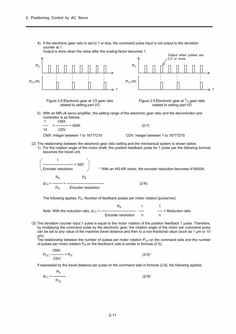
2. Positioning Control by AC Servo
2-11
4) If the electronic gear ratio is set to 1 or less, the command pulse input is not output to the deviation
counter at 1. Output is done when the value after the scaling factor becomes 1.
Figure 2.8 Electronic gear at 1/2 gear ratio Figure 2.9 Electronic gear at 2/5 gear ratio related to setting part I/O related to setting part I/O
5) With an MR-J4 servo amplifier, the setting range of the electronic gear ratio and the denominator and
numerator is as follows. 1 CMX < < 4000 (2-7) 10 CDV
CMX: Integer between 1 to 16777215 CDV: Integer between 1 to 16777215 (2) The relationship between the electronic gear ratio setting and the mechanical system is shown below.
1) For the rotation angle of the motor shaft, the position feedback pulse for 1 pulse per the following formula becomes the travel unit.
1 × 360゚ Encoder resolution * With an HG-KR motor, the encoder resolution becomes 4194304.
PB PB
∆0 = = (2-8) Pf0 Encoder resolution
The following applies: Pf0: Number of feedback pulses per motor rotation [pulse/rev]
PB 1 1 Note: With the reduction ratio, ∆0 = = Reduction ratio Encoder resolution n n
(3) The deviation counter input 1 pulse is equal to the motor rotation of the position feedback 1 pulse. Therefore,
by multiplying the command pulse by the electronic gear, the rotation angle of the motor per command pulse can be set to any value of the machine travel distance and then to a non-fractional value (such as 1 μm or 10 μm). The relationship between the number of pulses per motor rotation PC0 on the command side and the number of pulses per motor rotation Pf0 on the feedback side is similar to formula (2-5).
CMX PC0 = Pf0 (2-5)' CDV
If expressed by the travel distance per pulse on the command side in formula (2-8), the following applies:
PB ∆C = (2-8)' PC0
PC
PC1=Pf
t
PC
PC1=Pf
t
Output when pulses are 2.5 or more

2. Positioning Control by AC Servo
2-12
According to the relationship with (2-5), the following applies.
PB PB CMX CMX ∆c = = = ∆0 (2-9) PC0 Pf0 CDV CDV
Also, if the electronic gear ratio is set to the following, the travel distance per command pulse ∆c can be set to any value, regardless of the mechanical system (Pf0, PB).
CMX ∆C Pf0 = = ∆c (2-10) CDV ∆0 PB
(4) The motor speed is determined by the pulse train FC1, which is input to the deviation counter after multiplying
the command pulse by the electronic gear ratio. Thus, the motor can be rotated at a high speed by making fC1 large, even if the number of output pulses from the positioning controller (command pulse frequency) fC is small. When the motor is at a constant speed, the input pulse frequency of the deviation counter (fC1) and the feedback pulse frequency fF are balanced. Therefore, the relationship between the motor speed and the electronic gear is expressed by formula (2-11).
CMX N fc1 = fc = Pfo (2-11) CDV 60
The following applies: fC: Command pulse frequency [pps]
fC1: Deviation counter input pulse frequency [pps] N: Motor speed [r/min]
Therefore, the electronic gear ratio when operating the motor with the speed N and the command pulse frequency fc is as follows:
CMX fC1 1 N = = Pfo (2-12) CDV fC fC 60
For example, the electronic gear ratio to rotate the servo motor (HG-KR Series) at 3000 r/min with a command pulse frequency of 200 kpps,
CMX , is as follows: CDV
CMX 1 3000 131072 = × 4194304 × = CDV 200000 60 125

2. Positioning Control by AC Servo
2-13
Example 2.1 Calculate assuming that the differential driver is used. Question 1: Find the machine travel distance ∆0 per feedback pulse. Question 2: Find the servo amplifier side electronic gear ratio K when the QD75-side electronic gear is 1/1 and
the machine travel distance ∆C=0.05 [μm/pulse]. Question 3: For K found in question (2), find the command pulse frequency fc when the motor operates at 3000
[r/min]. Question 4: Find the servo amplifier side electronic gear ratio K when the command pulse frequency is 4 Mpps. Question 1: According to formula (2-8), the following applies:
PB 8 ∆0 = = 0.0019 × 10⁻³[mm/pulse] Pf0 4194304 * When the positioning is 300 mm, 300÷0.0019×10-3=157894736.842 pulses and comes out to be a
fraction. Question 2: Calculate the electronic gear ratio to control the servo motor with the travel distance per feedback pulse (0.0019×10⁻³ [mm/pulse]) by the machine travel distance (0.05×10⁻³ [mm/pulse]) of the positioning device.
According to formula (2-10),
CMX Pf0 4194304 1 4194304 16384 K= =∆c =0.05×10⁻³ × = × = CDV PB 8 20000 8 625 ∆C after putting the above-mentioned electronic gear is as follows:
PB CMX 8 16384 ∆C = × = × = 0.00005 [mm/pulse] Pf0 CDV 4194304 625 * When the positioning is 300 mm, 300÷0.00005=6000000 pulses, and it is not a fraction. * By using the electronic gear ratio found above, it is necessary to verify that the maximum command
frequency for the QD75 positioning controller does not exceed 4 Mpps.
fc Positioning Data
CMX
CDV
Deviation
counterSM
PLG
A
HG-KR servo motor V
Feed screw lead PB=8 [mm/rev]
Pf0
Electronic gear CMX ≤ 16777215 CDV ≤ 16777215 CMX/CDV
=1/10 to 4000 Servo motor HG-KR: 3000 r/min
4194304 p/rev
QD75 positioning controller
Ap
Al×Am
MR-J4 servo amplifier
Setting unit 1/10 μm 1/105 inch 1/105 degree 1 pulse
Travel distance per pulse Ap ≤ 65535 Al ≤ 65535 Am = 1, 10, 100, 1000 Ap (Number of pulses per revolution) Al (Travel distance per revolution) Am (unit scaling)
Maximum pulse command frequencyQD75PN
Open collector, 200 kpps QD75DN
Differential driver, 4 Mpps
Pf0=4194304 p/rev PB=8 mm Speed: 24 m/min
CMX = ?CDV = ?
Ap = ? Al =

2. Positioning Control by AC Servo
2-14
Question 3: According to formula (2-11), the following applies: N 3000 fC1 = Pf0 × = 4194304 × = 209715200 [pps] 60 60
According to formula (2-6), the following applies:
CDV 625 fC = fC1 = × 209715200 = 8000000 = 8 [Mpps] CMX 16384 * The command pulse frequency exceeds 4 Mpps, which is the maximum command pulse frequency for
QD75DN, so control is not possible. (→ Find the electronic gear on the servo amplifier side when the maximum command pulse frequency for QD75DN is 4 Mpps.)
Question 4: According to formula (2-6), the following applies:
CDV CMX fC1 209715200 32768 fC = fC1 ⇒ = = = CMX CDV fC 4×10⁶ 625 Check the positioning accuracy ∆0 after placing the above-mentioned electronic gear.
PB CMX 8 32768 ∆C = × = × = 0.0001 [mm/pulse] Pf0 CDV 4194304 625
Summary of example 2.1 Consider this when positioning is 300 mm.
CAUTION
Because the maximum command pulse frequency differs from the used positioning controller, care must be taken when checking the calculation result. Example Maximum command pulse frequency for QD75D positioning controller QD75D: 1 Mpps QD75DN: 4 Mpps
fc Positioning Data
CMX=32768
CDV=625
Deviation
counterSM
PLG
A
HG-KR servo motor V
Positioning travel distance: 300 [mm]
Pf0
Number of pulses after electronic gear ratio of servo amplifier (Number of motor command
pulses) 157286400 [pulses]
QD75 positioning controller
Ap=1
Al=1×Am=1
MR-J4 servo amplifier
Positioning data 3000000 [pulses]
(300 [mm]÷0.0001 [mm/pulse])
Number of command pulses
3000000 [pulses] Pf0=4194304 p/rev
PB=8 mmMotor speed 37.5 R

2. Positioning Control by AC Servo
2-15
2.5.2 Maximum Input Pulse Frequency The maximum servo amplifier input frequency is determined by the following conditions. (1) For the MR-J4 Series, select the value of the electronic gear from formulas (2-11) and (2-12) so that the
servo motor can be used up to the rated speed with the maximum input pulse frequency (open collector: 200 kpps; differential driver: 4 Mpps). In addition, the overall maximum input pulse frequency including the controller is the maximum frequency satisfying the abovementioned servo amplifier as well as controller. (For the maximum output pulse frequency of the positioning controller, refer to Appendix 3.)
Example 2.2 (1) The maximum input pulse frequency for open collector input of the MR-J4 (3000 r/min) Series is how
many kpps? (2) Find the range of electronic gear K for the MR-J4 when using the MR-J4 rated speed under the maximum
input pulse frequency. (3) With open collector input, the maximum input pulse frequency for the overall MR-J4 and QD75 is how
many kpps?
1) The answer is 200 kpps. 2) According to (2-11) and (2-12), the range of electronic gear value K is as follows.
3000 3000 fC1 209715.2×103 1048576 fC1 = Pf0 × = 4194304 × = 209715.2 × 103 pps 4000 > K ≥ = = 60 60 fC 200×103 1000
3) The frequency that satisfies both MR-J4 and QD75 is 200 kpps.
Example 2.3 (1) The maximum input pulse frequency for differential driver input of the MR-J4 (3000 r/min) Series is how
many kpps? (2) Find the range of electronic gear K for the MR-J4 when using the MR-J4 rated speed under the maximum
input pulse frequency. (3) With differential driver input, the maximum input pulse frequency for the MR-J4 and QD75 overall is
how many kpps?
1) The answer is 4 Mpps. 2) According to (2-11) and (2-12), the range of electronic gear value K is as follows.
3000 3000 fC1 209715.2×103 524288
fC1 = Pf0 × = 4194304 × = 209715.2 × 103 pps 4000 > K ≥ = = 60 60 fC 4×10⁶
10000
3) The frequency that satisfies both MR-J4 and QD75 is 4 Mpps.

2. Positioning Control by AC Servo
2-16
2.6 Speed Pattern and Stop Settling Time 2.6.1 Speed Pattern and Droop Pulse Behavior Droop pulse is the difference between command pulses and feedback pulses in the servo amplifier deviation counter. The behavior is shown in Figure 2.10.
(1) Operation between t0 and t2 Regarding the command pulse, the feedback pulse from the encoder is delayed due to the acceleration delay of the servo motor, and droop pulse ε is generated.
fC1 KfC ε= = [pulse] (2-13) PG1 PG1 PG1: Model loop gain
CMX K:
CDV (2) Operation between t2 and t3
While maintaining the delay of droop pulse in formula (2-13), operation is performed through synchronization of the command pulse and the servo motor speed.
(3) Operation between t3 and t4
Operates to recover the position delay in formula (2-13). Also, for t4 (as soon as command pulses come to an end), the motor does not reach the command position, but is still ran even if the command pulses come to an end.
(4) Operation between t4 and t5
Operates to let out all of the remaining droop pulses. The time between this t4 and t5 is called stop settling time ts.
(5) Motor motion
The actual motion is exponential to the motor speed as well as the droop pulses. At the end, it is stabilized with all the droop pulses out and enters a servo-lock status. The result is as follows. Command quantity of command pulse (area ABCD) = Actual feed length (area AECF) and Acceleration time saving (1) (area ABEA) = Deceleration time decrease (2) (area CFDC)
Figure 2.10 Speed pattern and droop pulse
F
t 0 t 1 t 2 t 4 t 5t
[sec]t 3 D
CEB
A
Tpsd ts
Feedback pulse(Actual movement)
Command pulse
① ②
[pps]
Pul
sefr
eque
ncy

2. Positioning Control by AC Servo
2-17
Example 2.4
With PG1 = 36 [sec-1] on the left, find droop pulse ε for the following deviation counter input. fC1 = KfC = 180 k, 18 k, 0.9 k, 72 [pps] Also covert the droop pulse into the feed length when ∆0 = 0.01 [mm/pulse]. However, when an MR-J4 motor is used, the following applies: (Electronic gear ratio K=1/16)
If ε = KfC/PG1 [pulse], the following can be assumed. When KfC = 180 kpps (1318 r/min)
180000 ε = = 5000 [pulses], feed length conversion value 5000×0.01=50 [mm]
36 When KfC = 18 kpps (132 r/min)
180000 ε = = 500 [pulses], feed length conversion value 500×0.01=5 [mm]
36 When KfC = 0.9 kpps (6.6 r/min)
900 ε = = 25 [pulses], feed length conversion value 25×0.01=0.25 [mm]
36 When KfC = 72 pps (0.53 r/min)
72 ε = = 2 [pulses], feed length conversion value 2×0.01=0.02 [mm]
36 2.6.2 Stop Settling Time ts The stop settling time is the time from the end of command output until positioning is completed. For the part mounters such as the inserter and the mounter, the cycle time is determined by this settling time, thus time minimization is a very important factor.
Stop setting time Command
Droop pulse
t[sec]
[pps]
t 0 t 1 t 2 t 4 t 5t 3
Pul
sefr
eque
ncy

2. Positioning Control by AC Servo
2-18
The stop settling time is enabled to obtain the approximate value by model side position loop gain 1 (PG1) for model adaptive control. However, the value of position loop gain 1 is significantly affected by the machine condition and the value of the load moment of inertia. Therefore, it is necessary to consider the compatibility, including the mechanical system, when a feed of high-frequency operation or a high-response stop setting is required. The stop settling time until the pulses are approximately 10 or less is empirically shown in the following formula.
3 ts (sec)
PG1 If the droop pulses are within the precision required by the machine, the servo motor is considered stopped even if it is running. Also, a positioning completed signal is output. The stop settling time affects the cycle time during high-frequency positioning.
2.7 Relationship between Machine System and Response Level Setting 2.7.1 Response Level Setting With standard control methods, it was necessary to adjust the servo position loop gain or the speed loop gain to match the respective machine conditions. Especially with the ratio of load inertia or machine rigidity, this required sufficient knowledge of the relationship between each loop of the servo system, and adjustment was much more time-consuming. In the MELSERVO-J4 Series, model adaptive control and real-time auto tuning is performed, so the ideal model part as well as the actual loop part are automatically set to the most appropriate gain only by setting the auto tuning response to the value that matches the machine rigidity. Auto tuning response settings can be configured using the parameters. Refer to the summary of MR-J4 in the following table.
Table 2.3 MR-J4 parameter number PA09
Setting value Auto tuning
response Machine target
1 to 13 Slow response Items with a low machine rigidity. Machines with a belt, chain drive, and a large backlash.
14 to 18 Low-to-medium
response Rigidity level of an average, general-purpose machine. Belt, chain, rack and pinion drive, etc. Default setting value.
19 to 23 Medium response Slightly higher level of machine rigidity. For response improvement through a ball screw, a timing belt with high rigidity, etc.
24 to 28 Mid-to-high response Applications with high machine rigidity and when performing positioning very frequently.
29 to 40 Fast response Applications with a very high machine rigidity and when performing positioning very frequently.
Note: Decrease the setting value if hunting occurs in the machine or if the gear noise is loud.
To improve the performance so as to shorten the stop settling time, increase the setting value.
10 pulses 0 pulsesCommand
tS t
When parameter number PA10 is set to 10
In-position signal ON

2. Positioning Control by AC Servo
2-19
2.7.2 Real-Time Auto Tuning If the servo motor is operated by setting the setting value of the auto tuning response to the parameter, the load moment of inertia at that time is auto tuned and the gain for each control loop (position, speed) is set to the most appropriate value with respect to the response setting value already set. At this time, if the setting value of the auto tuning response is not appropriate, unstable occurs due to the generation of vibration. Because of this, it is necessary to review the setting value of the auto tuning response. The result of the tuned load moment of inertia can be checked by the load to motor inertia ratio on the status display monitor. The recommended load to motor inertia ratio has limitations on response, regenerative power, dynamic brake, etc. Normally, the load to motor inertia ratio for the servo motor is recommended to be 30 times or less, as a guide. (For details, refer to the individual catalog.) Setting by real-time auto tuning is possible for a majority of machines, but if adjustment to the limit is required, perform gain adjustment manually.
<Reference> Manual gain adjustment method If the load moment of inertia is excessive, the unbalanced load on the lifts shaft will be enormous, and normal tuning will not be possible. In this case, or when the machine is not compatible with the auto tuning response setting, perform each gain adjustment manually. For details, refer to section 5.3.3.

2. Positioning Control by AC Servo
2-20
Memo

3. Positioning Controller
3-1
3.1 Division of Servo Function and Positioning Controller In positioning control by an AC servo, the functions are divided as follow s by the servo amplifie r and the positioning controller, which generates the command pulse train.
3.1.1 Positioning Controller Side Functions
(1) Command pulse output corresponding to the feed length of a machine (2) Determination of machine speed (command pulse frequency) (3) Determination of operation pattern (acceleration/deceleration time constant) (4) Storing of the logical machine position
3.1.2 Servo Amplifier Side Functions
(1) Positioning control over the command position, according to the pulse train from the positioning controller (2) Servo-lock function (3) Positioning completed signal output function
3.2 Positioning Controller Classification and Configuration
Figure 3.1 Positioning system configuration
(1) The pulse trains output from the positioning module are added up by the deviation counter. The droop amount of this pulse is converted into D/A, becomes DC analog voltage, and then a speed command.
(2) The motor rotates according to the speed command. At the same time, a feedback pulse is returned to the deviation counter by the encoder, and the droop pulse is reduced.
(3) When the pulse train from the pos itioning module becomes a decelerat ion command, the droop pulses of the deviation counter disappear and the motor stops.
Setting data
Sequence program
CMXCDV
Deviationcounter
SM
Encoder
Output Y
Forward pulse train
A
Feedback pulse
Speed command
Programmable controller Servo amplifier
Input X
Positioning module
Reverse rotation
pulse train
D/A converter
Servo motor
Electronic gear
Data read/write
Parameter data Positioning data Home position
return data
Peripheral equipment

3. Positioning Controller
3-2
The servo motor has a wide range of applications, and a large number of items have been proposed and manufactured for positioning devices for the servo motor during progressing systemization with the host controller Therefore, the selection of a suitable positioning controller, similar to the selection of a servo motor, is a very important point for servo system efficiency and for pursuing cost performance. With the above points in mind, the classification and functions of various positioning controllers are explained below.
QD77MSQD75PN/QD75DNQD75M/QD75MHQD70P4/QD70P8
Systemmethod
Stand-alone type(Amplifier with built-inpositioning function)
Sequencer familytype
FX series
Q series
MR - J2S - CP
F X 2 N - 1 P GF X 2 N- 1 0 G MF X 2 N- 1 0 G MF X 2 N- 2 0 G MF X 3 U - 20SSC-H
+
+Servo amplifierServo motor
Servo amplifierServo motor
Multi axiscontroller system
Motioncontroller Q172/Q173 series+
Servo amplifierServo motor
*See Appendix3 for modelselection
MR - J3 - T
L seriesLD77MHLD75P4/LD75D4
Servo amplifierServo motor
+
+
+
+
+
(1) System method
The servo system method, including positioning controllers and servo amplifier, is as follows. (2) Number of controlled axes
The number of servo motors or servo amplifiers that can generally be simultaneously controlled by one positioning controller is expressed. With multiple controlled axes, control is divided into either the simultaneous control method or the independent control method.
1 axis ·········· QD75P1(N), QD75D1(N), QD75M1, QD75MH1, FX2N-10GM,
MR-J2SCP, etc. 2 axis ·········· QD75P2(N), QD75D2(N), QD75M2, QD75MH2, QD77MS2, A1SD75M2,
FX2N-20GM, FX3U-20SSC-H, etc.
Number of controlled axes
4 axis ·········· QD75P4(N), QD75D4(N), QD75M4, QD75MH4, QD77MS4, QD70P4, LD75P4, LD75D4, LD77MH4
8 axis ·········· QD70P8, Q172 series 16 axis ········· Q172(DS), QD77MS16, LD77MH16 32 axis ········· Q173 series
(3) Simultaneous control and independent control 1) Simultaneous control: This function controls multiple axes simultaneously if a positioning controller has two or
more controlled axes. This means that control of multiple axes is performed by a single program, and the operation mode (auto, manual, home position return, etc.), starting, and stopping are performed simultaneously. Also for such cases, these days many positioning controllers are equipped with interpolation control.
2) Independent control: This function controls each axis independently if a positioning controller has two or more controlled axes. This means that control of multiple axes is performed by individual programs, and the operation mode (auto, manual, home position return, etc.), starting, and stopping is also performed individually.

3. Positioning Controller
3-3
(4) Interpolation control
This function controls multiple axes using interconnectivity, and there is generally linear interpolation and circular interpolation. 1) Linear interpolation: Multiple axes are controlled so as to be connected (linked) as closely as possible
from the starting point up to the end point (target position). Trajectory becomes linear in this situation, which is why it is called linear interpolation. There is generally linear interpolation of 2 axes and 3 axes.
(a) Linear interpolation of 2 axes (b) Linear interpolation of 3 axes
Figure 3.2 Linear interpolation operation
Applicable models Linear interpolation of 2 axes FX2N-20GM, QD75P2(N), QD75D2(N), QD75MH2, QD75M2, QD77MS2, FX3U-20SSC-H etc.
Linear interpolation of 3 axes QD75P4(N), QD75D4(N), QD75M4, QD75MH4, QD77MS4, QD77MS16, Q172, Q173, LD75P4, LD75P4, LD77MH4/MH16 etc. (Linear interpolation of 2 axes is also possible)
2) Circular interpolation: Multiple axes are controlled so as to be connected (linked) circularly from the starting
point to the end point (target position). There are countless items in the trajectory of a circular arc connecting between the two points, thus the position of two points is specified by the program along with the radius of the circular arc, the center position, the direction etc.
CW
CCW
Starting point Trajectory of arc center
End point
Figure 3.3 Circular interpolation operation
Applicable models FX2N-20GM, FX3U-20SSC-H, QD75P2(N)/P4(N), QD75D2(N)/D4(N),
QD75M2/M4, QD75MH2/MH4, QD77MS2/MH4/MH16, Q172, Q173, LD75P4, LD75D4, LD77MH4/MH16 etc.
Y axis
X axis Starting point
End point
Y axis
X axis
Starting point
End point
Z axis
Reverse rotation
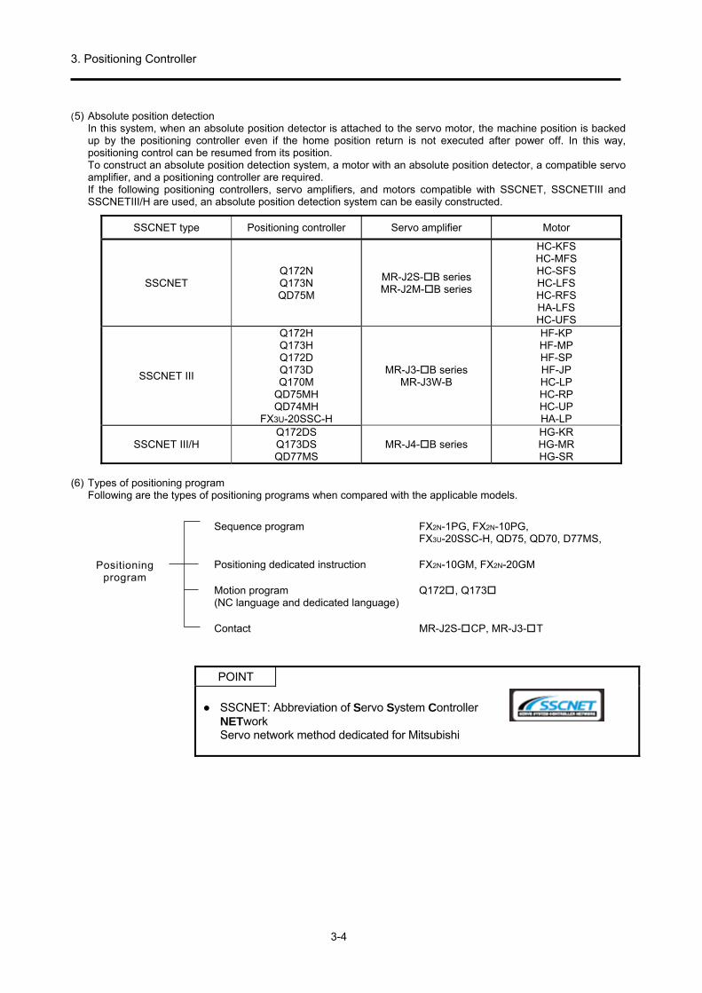
3. Positioning Controller
3-4
(5) Absolute position detection In this system, when an absolute position detector is attached to the servo motor, the machine position is backed up by the positioning controller even if the home position return is not executed after power off. In this way, positioning control can be resumed from its position. To construct an absolute position detection system, a motor with an absolute position detector, a compatible servo amplifier, and a positioning controller are required. If the following positioning controllers, servo amplifiers, and motors compatible with SSCNET, SSCNETIII and SSCNETIII/H are used, an absolute position detection system can be easily constructed.
SSCNET type Positioning controller Servo amplifier Motor
SSCNET Q172N Q173N QD75M
MR-J2S-B series MR-J2M-B series
HC-KFS HC-MFS HC-SFS HC-LFS HC-RFS HA-LFS HC-UFS
SSCNET III
Q172H Q173H Q172D Q173D Q170M
QD75MH QD74MH
FX3U-20SSC-H
MR-J3-B series MR-J3W-B
HF-KP HF-MP HF-SP HF-JP HC-LP HC-RP HC-UP HA-LP
SSCNET III/H Q172DS Q173DS QD77MS
MR-J4-B series HG-KR HG-MR HG-SR
(6) Types of positioning program
Following are the types of positioning programs when compared with the applicable models.
Positioning program
Sequence program FX2N-1PG, FX2N-10PG, FX3U-20SSC-H, QD75, QD70, D77MS,
Positioning dedicated instruction FX2N-10GM, FX2N-20GM
Motion program Q172, Q173 (NC language and dedicated language)
Contact MR-J2S-CP, MR-J3-T
POINT
SSCNET: Abbreviation of Servo System Controller
NETwork Servo network method dedicated for Mitsubishi
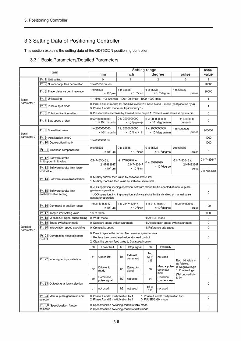
3. Positioning Controller
3-5
3.3 Setting Data of Positioning Controller This section explains the setting data of the QD75DN positioning controller.
3.3.1 Basic Parameters/Detailed Parameters
Item Setting range Initial
value mm inch degree pulse
Basic parameter 1
Pr.1 Unit setting 0 1 2 3 3
Pr.2 Number of pulses per rotation 1 to 65535 pulses 20000
Pr.3 Travel distance per 1 revolution 1 to 65535 × 10-1 m
1 to 65535 × 10-5 inch
1 to 65535 × 10-5 degree
1 to 65535 pulses
20000
Pr.4 Unit scaling 1: 1 time 10: 10 times 100: 100 times 1000: 1000 times 1
Pr.5 Pulse output mode 0: PULSE/SIGN mode; 1: CW/CCW mode; 2: Phase A and B mode (multiplication by 4);
3: Phase A and B mode (multiplication by 1) 1
Pr.6 Rotation direction setting 0: Present value increase by forward pulse output 1: Present value increase by reverse l t t
0
Pr.7 Bias speed at start 0 to 2000000000 × 10-2 mm/min
0 to 2000000000
× 10-3 inch/min0 to 2000000000 × 10-3 degree/min
0 to 4000000 pulses/s
0
Basic parameter 2
Pr.8 Speed limit value 1 to 2000000000
× 10-2 mm/min
1 to 2000000000
× 10-3 inch/min
1 to 2000000000
× 10-3 degree/min 1 to 4000000 pulses
200000
Pr.9 Acceleration time 0 1 to 8388608 ms
1000
Pr.10 Deceleration time 0 1000
Detailed parameter 1
Pr.11 Backlash compensation 0 to 65535
× 10-1 μm
0 to 65535
× 10-5 inch
0 to 65535
× 10-5 degree
0 to 65535
pulse 0
Pr.12 Software stroke limit upper limit value -2147483648 to
2147483647
× 10-1 μm
-2147483648 to
2147483647
× 10-5 inch
0 to 35999999
× 10-5 degree
-2147483648 to
2147483647
pulse
2147483647
Pr.13 Software stroke limit lower limit value
-2147483648
Pr.14 Software stroke limit selection 0: Multiply current feed value by software stroke limit
1: Multiply machine feed value by software stroke limit 0
Pr.15 Software stroke limit enable/disable setting
0: JOG operation, inching operation, software stroke limit is enabled at manual pulse generator operation
1: JOG operation, inching operation, software stroke limit is disabled at manual pulse generator operation
0
Pr.16 Command in-position range 1 to 2147483647
× 10-1 μm
1 to 2147483647
× 10-5 inch
1 to 2147483647
× 10-5 degree
1 to 2147483647
pulse 100
Pr.17 Torque limit setting value 1% to 500% 300
Pr.18 M-code ON signal output timing 0: WITH mode 1: AFTER mode 0
Pr.19 Speed switchover mode 0: Standard speed switchover mode 1: Acceleration speed switchover mode 0
Pr.20 Interpolation speed specifying 0: Composite speed 1: Reference axis speed 0
Pr.21 Current feed value at speed control
0: Do not replace the current feed value at speed control
1: Replace the current feed value at speed control
2: Clear the current feed value to 0 at speed control
0
Pr.22 Input signal logic selection
b0 Lower limit b3 Stop signal b6 Proximity i l
Each bit value is as follows. 0: Negative logic 1: Positive logic
(Set unused bits to 0)
0 b1 Upper limit b4
External command
b7,
b9 to b15
not used
b2 Drive unit ready
b5Zero-point signal
b8 Manual pulse generator input
Pr.23 Output signal logic selection
b0 Command pulse signal
b2 not used b4 Deviation counter clear
0
b1 not used b3 not used b5 to b15
not used
Pr.24 Manual pulse generator input selection
0: Phase A and B multiplication by 4 1: Phase A and B multiplication by 2 2: Phase A and B multiplication by 1 3: PULSE/SIGN mode
0
Pr.150 Speed/position function selection
0: Speed/position switching control of INC mode
2: Speed/position switching control of ABS mode 0

3. Positioning Controller
3-6
Item Setting range Initial
value mm inch degree pulse
Detailed
parameter 2
Pr.25 Acceleration time 1
1 to 8388608 ms
1000
Pr.26 Acceleration time 2 1000
Pr.27 Acceleration time 3 1000
Pr.28 Deceleration time 1 1000
Pr.29 Deceleration time 2 1000
Pr.30 Deceleration time 3 1000
Pr.31 JOG speed limit value 1 to 2000000000 × 10-2 mm/min
1 to 2000000000 × 10-3 inch/min
1 to 2000000000 × 10-3 degree/min
1 to 4000000 pulses 20000
Pr.32 JOG operation acceleration time selection
0 to 3
0
Pr.33 JOG operation deceleration time selection
0
Pr.34 Acceleration/deceleration processing selection
0: Automatic trapezoid acceleration/deceleration processing
1: S-curve acceleration/deceleration processing 0
Pr.35 S-curve ratio 1% to 100% 100
Pr.36 Sudden stop deceleration time 1 to 8388608 ms 1000
Pr.37 Stop group 1 sudden stop selection 0: Normal deceleration stop
1: Sudden stop
0
Pr.38 Stop group 2 sudden stop selection 0
Pr.39 Stop group 3 sudden stop selection 0
Pr.40 Positioning complete signal output time
0 to 65535 ms 300
Pr.41 Circular interpolation error permissible range
0 to 100000
× 10-1 μm
0 to 100000
× 10-5 inch
0 to 100000
× 10-5 degree
0 to 100000
pulse 100
Pr.42 External command function selection 0: External positioning start 1: External speed change request
2: Speed/position/position-speed control switching request 3: Skip request 0
3.3.2 Home Position Return Basic Parameters/Home Position Return Detailed Parameters
Item Setting range Initial
value mm inch degree pulse
Home position return basic parameter
Pr.43 Home position return types
0: Proximity dog method
1: Stopper (1) (By reaching the setting value of the dwell time)
2: Stopper (2) (By zero-point signal when reaching the stopper)
3: Stopper (3) (Method without proximity dog)
4: Count method (1) (Use zero-point signal)
5: Count method (2) (Do not use zero-point signal)
0
Pr.44 Home position return direction 0: Positive direction (address increasing direction)
1: Negative direction (address decreasing direction) 0
Pr.45 Home position address -2147483648 to 2147483647 × 10-1 μm
-2147483648 to 2147483647 × 10-5 inch
0 to 35999999 × 10-5 degree
-2147483648 to 2147483647 pulses
0
Pr.46 Home position return speed 1 to 2000000000 × 10-2 mm/min
1 to 2000000000 × 10-3 inch/min
1 to 2000000000 × 10-3 degree/min
1 to 4000000 pulses/s
1
Pr.47 Creep speed 1
Pr.48 Home position return retry 0: Do not retry home position return with upper/lower limit switch
1: Retry home position return with upper/lower limit switch 0
Home position return detailed parameter
Pr.49 Home position return dwell time 0 to 65535 ms 0
Pr.50 Travel distance setting after proximity dog signal is turned ON
0 to 2147483647
× 10-1 μm
0 to 2147483647
× 10-5 inch
0 to 2147483647
× 10-5 degree
0 to 2147483647
pulse 0
Pr.51 Home position return acceleration time selection
0 to 3
0
Pr.52 Home position return deceleration time selection
0
Pr.53 Home position shift distance -2147483648 to 2147483647 × 10-1 μm
-2147483648 to 2147483647 × 10-5 inch
0 to 35999999 × 10-5 degree
-2147483648 to 2147483647 pulse
0
Pr.54 Home position return torque limit value
1% to 300% 300
Pr.55 Deviation counter clear signal output time
1 to 65535 ms 11
Pr.56 Speed specification at home position shift time
0: Home position return speed
1: Creep speed 0
Pr.57 Dwell time at home position return retry 0 to 65535 ms 0

3. Positioning Controller
3-7
3.3.3 Positioning Data
Setting range Initial value Unit
Item mm inch degree pulse
Operation pattern
Exit (00): Positioning exit (Stop) Continuous (01): Continuous positioning control (Start following positioning data
numbers) Locus (11): Continuous path control (Run to the end point address of the following
positioning data numbers without stopping)
Exit
Peripheral equipment display Setup contents Code number 1: ABS linear 1 Linear control of 1 axis (ABS) 01H 2: INC linear 1 Linear control of 1 axis (INC) 02H 3: Fixed feed 1 Fixed feed control of 1 axis 03H 4: Forward rotation, speed 1 Speed control of 1 axis (forward rotation) 04H 5: Reverse rotation, speed 1 Speed control of 1 axis (reverse rotation) 05H 6: Forward rotation,
speed/position Speed/position switching control (reverse run) 06H
7: Reverse rotation, speed/position
Speed/position switching control (forward run) 07H
8: Forward rotation, position/speed
Position/speed switching control (forward rotation) 08H
9: Reverse rotation Position/speed
Position/speed switching control (reverse rotation) 09H
A: ABS linear 2 Linear interpolation control of 2 axes (ABS) 0AH B: INC linear 2 Linear interpolation control of 2 axes (INC) 0BH C: Fixed feed 2 Fixed feed control by linear interpolation of 2 axes 0 CH D: ABS circular interpolation
Auxiliary point specified circular interpolation control (ABS)
0DH
E: INC circular interpolation Auxiliary point specified circular interpolation control (INC)
0EH
F: ABS circular arc right Center point specified circular interpolation control (ABS, CW)
0FH
G: ABS circular arc left Center point specified circular interpolation control (ABS, CCW)
10H
Control method H: INC circular arc right Center point specified circular interpolation control (INC, CW)
11H -
I: INC circular arc left Center point specified circular interpolation control (INC, CCW)
12H
J: Forward rotation, speed 2 Speed control of 2 axes (forward rotation) 13H K: Reverse rotation, speed 2 Speed control of 2 axes (reverse rotation) 14H L: ABS linear 3 Linear interpolation control of 3 axes (ABS) 15H M: INC linear 3 Linear interpolation control of 3 axes (INC) 16H N: Fixed feed 3 Fixed feed control by linear interpolation of 3 axes 17H O: Forward rotation, speed 3 Speed control of 3 axes (forward rotation) 18H P: Reverse rotation, speed 3 Speed control of 3 axes (reverse rotation) 19H Q: ABS linear 4 Linear interpolation control of 4 axes (ABS) 1AH R: INC linear 4 Linear interpolation control of 4 axes (INC) 1BH S: Fixed feed 4 Fixed feed control by linear interpolation of 4 axes 1 CH T: Forward rotation, speed 4 Speed control of 4 axes (forward rotation) 1DH U: Reverse rotation, speed 4 Speed control of 4 axes (reverse rotation) 1EH V: NOP NOP instruction 80H W: Present value change present value change 81H X: JUMP instruction JUMP instruction 82H Y: LOOP LOOP to LEND start 83H Z: LEND LOOP to LEND end 84H
Acceleration time No. 0 to 3 (Select 0 to 3 for the acceleration time from basic parameter 2 and detailed parameter 2)
0
Deceleration time No. 0 to 3 (Select 0 to 3 for the deceleration time from basic parameter 2 and detailed parameter 2)
0

3. Positioning Controller
3-8
Setting range
Unit Initial valueItem mm inch degree pulse Interpolation target axis 0 to 3 (Set "Interpolation target axis" (partner axis) when performing interpolation
operation of 2 axes) 0: Keep axis 1 as interpolation target axis (partner axis) 1: Keep axis 2 as interpolation target axis (partner axis) 2: Keep axis 3 as interpolation target axis (partner axis) 3: Keep axis 4 as interpolation target axis (partner axis)
0
Pos
ition
ing
addr
ess
/ tra
vel d
ista
nce
Absolute (ABS) present value change
-214748364.8 to 214748364.7 μm
-21474.83648 to 21474.83647 inch
0 to 359.99999 degrees
-2147483648 to 2147483647 pulses
0
Increment (INC) fixed feed
-214748364.8 to 214748364.7 μm
-21474.83648 to 21474.83647 inch
-21474.83648 to 21474.83647 degrees
-2147483648 to 2147483647 pulses
0
Speed/position, position/speed switching control
0 to 214748364.7 μm
0 to 21474.83647 i nches
0 to 21474.83647 degree (Note)
0 to 2147483647 pulses
0
Circular address (Auxiliary point or center point)
-214748364.8 to 214748364.7 μm
-21474.83648 to 21474.83647 inch
- -2147483648 to 2147483647 pulses
0
speed command 0.01 to 20000000.00
mm/min 0.001 to 2000000.000
inches/min0.001 to 2000000.000
degrees/min1 to 4000000
pulses/s 0
Same speed as positioning data before -1 (current speed)
Dwell time
Except JUMP instruction
After 0 to 65535 ms (dwell time) has passed, the positioning completed signal is turned ON.
0 JUMP instruction
1 to 600 (positioning data No. before jump)
M code
JUMP instruction, excluding LOOP
0 to 65535 (M code)
0 JUMP instruction
0 to 10 (condition data No.) 0: Jump without conditions 1 to 10: Jump by satisfying conditions
LOOP 0 to 65535 (number of repeats)
Note: For speed-position switching control in the ABS mode, set an address of 0 to 359.99999. Positioning data setting example
Data No.
Operation pattern
Control method
Acceleration time [ms]
Decel- eration
time [ms]
Interpolationtarget axis
Positioning address / travel
distance [μm]
Circularaddress
Command speed
[mm/min]
dwell time [ms]
M code
1 0: Exit 1: ABS linear 1
0: 100 0: 100 - 50000.0 0.0 2000.00 0 0
2 0: Exit 1: ABS linear 1
0: 100 0: 100 - 75000.0 0.0 2000.00 0 0
3 0: Exit 1: ABS linear 1
0: 100 0: 100 - 100000.0 0.0 2000.00 0 0
4 0: Exit 1: ABS linear 1
0: 100 0: 100 - 150000.0 0.0 2000.00 0 0
5 0: Exit 1: ABS linear 1
0: 100 0: 100 - 200000.0 0.0 2000.00 0 0
6 0: Exit 1: ABS linear 1
0: 100 0: 100 - 25000.0 0.0 2000.00 0 0
7 0: Exit 0: Not
specified 0: 100 0: 100 -
0.0 0.0 0.00 0 0
8 0: Exit 0: Not
specified 0: 100 0: 100 -
0.0 0.0 0.00 0 0
9 0: Exit 0: Not
specified 0: 100 0: 100 -
0.0 0.0 0.00 0 0
10 0: Exit 0: Not
specified 0: 100 0: 100 -
0.0 0.0 0.00 0 0

3. Positioning Controller
3-9
3.4 Position Command Interface In the past, a pulse train was generally output as a position command from the positioning controller to the servo amplifier. Recently, however, with the conversion into software and digitization of each module by micro processors (CPUs), a new method to link bus lines with CPUs for positioning controllers and servo amplifiers has also emerged. Thus, it has becomes possible to construct advanced systems with increased accuracy. Also, in the pulse train method, there are several types of interfaces. A summary with the applicable models and respective characteristics is shown below.
Position command interface
Bus linking method [Positioning controller] (compatible with SSCNET) Q172, Q173, FX3U-20SSC-H, QD75M,
QD75MH, LD77MH, QD77MS [Servo amplifier] MR-J2S-B, MR-J2M-B, MR-J3-B, MR-J4-B
Pulse train method [Positioning controller] (general-purpose interface) FX2N-1PG, FX2N-10PG, FX2N-10GM,
FX2N-20GM, QD75P(N), QD75D(N), QD70, LD75P/D, etc. [Servo amplifier] MR-J4-A, MR-J3-A, MR-J2S-A etc.
Contact method [Servo amplifier with built-in positioning function](integrated amplifier) MR-J2S-CP, MR-J3-T
[Types of pulse train interfaces] (1) Forward/reverse rotation pulse train method and pulse train/direction identification signal method
To specify the rotation direction of a motor for the pulse train, one method is to input from different terminals according to the rotation direction, and another is a switching method according to the rotation direction identification signal. Also, there is a 2-phase pulse train method for input of the pulse train directly from the synchronous encoder.
Forward run pulse train
Reverse run pulse train
(a) Forward/reverse pulse train method
Pulse train
Directiondetermination signal
(b) Direction determination signal method
Forward Reverse
Phase A pulse train
Phase B pulse train
(c) Two-phase pulse train method
Figure 3.4 Rotation direction command method

3. Positioning Controller
3-10
(2) Open collector output type and differential driver output type These are the 2 types of interface hardware. A simple open collector output type was the standard, but the differential driver output type is increasingly used these days due to high-speed pulse trains and the improvement of noise resistance. Mitsubishi's QD75D is a differential driver output type, and the QD75P is an open collector output type.
[Hardware configuration example]
24 V DC
2 m or less
Servo amplifier
Maximum input pulsesFrequency, 200 kbps
Approx. 1.2 kΩ
Equivalent to Am26LS31
10 m or less
Servo amplifier
Maximum input pulsesFrequency, 4 Mpps
Approx.100Ω
(a) Open collector output type (Max. 200 kpps) (b) Differential driver output type (Max. 4 Mpps)
Figure 3.5 Example of pulse train hardware [Pulse train form]
Figure 3.6 Pulse train form
Pulse train
Common
(a) Open-collector type
Pulse train
Pulse train
(b) Differential driver

3. Positioning Controller
3-11
3.5 Fundamentals of Positioning Control with the Positioning Controller
3.5.1 Travel Direction of Machine and Rotation Direction of Servo Motor Counterclockwise rotation direction of the servo motor is considered forward rotation when viewed from the load side. Also, the positive direction of machine travel is generally the direction with increasing coordinates. When it becomes necessary to change the rotation direction of the servo motor so as to match the travel direction of the machine and the rotation direction of servo motor, change the rotation direction setting using the positioning controller parameters. Normal operation cannot be performed if there is a change in the rotation direction due to a change in the servo motor side phase. Therefore, do not change it. The method of changing this rotation direction is the same even if the positioning controller model is different. In addition, check the rotation direction using a function like the JOG operation mode.
Forward rotation (CCW)
Reverse rotation (CW)
Ball screw
Table
Servo motor
Direction of table from ball screwwhen motor is running forward
Direction in which the current position of the machinewill increase
Home position
Figure 3.7 Servo motor rotation direction Figure 3.8 Rotation direction setting example For the model shown in Figure3.8, the servo motor moves in the forward rotation in the direction in which the coordinates are decreased for the machine (negative direction). Therefore, in this case, set the rotation direction of the servo motor as reverse rotation in the positioning controller.
POINT
Forward rotation CCW: Abbreviation of counterclockwise
Reverse rotation CW: Abbreviation of clockwise

3. Positioning Controller
3-12
3.5.2 Types of Home Position Return 1) Types of home position return
Types of home position return
Types of home position
Operation description
Ma
nu
al/
au
to h
om
e p
os
itio
n
Proximity dog type home
position return
Machine home position
(First home position)
The creep speed decelerates according to the proximity dog signal OFF→ON, the output pulses are stopped by the zero-point signal from the servo amplifier after the proximity dog ON→OFF, and a clear signal is output. Then, the droop pulses of the deviation counter become zero, and the home position return is completed.
Fast OPR
Machine home position
(First home position)
Returning to the machine home position only using the home position return speed (high-speed) and without using the creep speed is called home position return. Initially, it is necessary to fix the machine home position with the dog type home position return.
Au
to h
om
e
po
sit
ion
re
turn
Program home position return
Program home position
(Second home position)
Returning to the program home position (standby position) set by the parameters using the home position return speed is called home position return.
Dog type home position return, fast home position return, and program home position return operations
Dog type homeposition return
Fast OPRHome position return speed
Machine OPR
Proximity dog
Program home position return
Home position shift distance
(Set by the parameter)
Machine home position
Zero-point signal
Program home position
(Second home position)
Creep speed
(First home position)
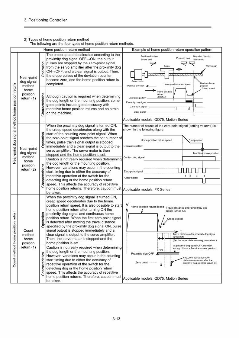
3. Positioning Controller
3-13
2) Types of home position return method The following are the four types of home position return methods.
Home position return method Example of home position return operation pattern
Nea
r-po
int d
og s
igna
l met
hod
hom
e po
sitio
n re
turn
Near-point dog signal
method home
position return (1)
Ope
ratio
n
The creep speed decelerates according to the proximity dog signal OFF→ON, the output pulses are stopped by the zero-point signal from the servo amplifier after the proximity dog ON→OFF, and a clear signal is output. Then, the droop pulses of the deviation counter become zero, and the home position return is completed.
Positive direction
Stroke end
Operation pattern
Proximity dog signal
Clear signal
Home position return speed
Home positionreturndirection
Positive direction
Table
Proximity dog
Machine homeposition
Servo motor
Negative direction
Stroke end
Worm gear
Creep speed
Zero-point signal
Cha
ract
eris
tics
Although caution is required when determining the dog length or the mounting position, some good points include good accuracy with repetitive home position returns and no strain on the machine.
Applicable models: QD75, Motion Series
Near-point dog signal
method home
position return (2)
Ope
ratio
n
When the proximity dog signal is turned ON, the creep speed decelerates along with the start of the counting zero-point signal. When the zero-point signal reaches the set number of times, pulse train signal output is stopped immediately and a clear signal is output to the servo amplifier. The servo motor is then stopped and the home position is set.
The number of counts of the zero-point signal (setting value=4) is shown in the following figure.
Operation pattern
Contact dog signal
Zero-point signal
Clear signal
Home position return speed Creep speed
Machine home position
1 2 3 4
Cha
ract
eris
tics
Caution is not really required when determining the dog length or the mounting position. However, variations may occur in the counting start timing due to either the accuracy of repetitive operation of the switch for the detecting dog or the home position return speed. This affects the accuracy of repetitive home position returns. Therefore, caution must be taken.
Applicable models: FX Series
Co
un
t m
eth
od
ho
me
po
sit
ion
re
turn
Count method home
position return (1)
Ope
ratio
n
When the proximity dog signal is turned ON, creep speed decelerates due to the home position return speed. It is also possible to start home position return after turning ON the proximity dog signal and continuous home position return. When the first zero-point signal is detected after moving the travel distance specified by the proximity dog signal ON, pulse signal output is stopped immediately and a clear signal is output to the servo amplifier. Then, the servo motor is stopped and the home position is set.
V
tTravel distance after proximity dog signalturned ON
(Set the travel distance using parameters.)
Creep speed
Travel distance after proximity dogsignal turned ON
Home position return speed
Zero point
Proximity dog OFFON
First zero-point after traveldistance movement after theproximity dog signal is turned ON
At proximity dog signal OFF, maintainenough distance from the current position.
Cha
ract
eris
tics
Caution is not really required when determining the dog length or the mounting position. However, variations may occur in the counting start timing due to either the accuracy of repetitive operation of the switch for the detecting dog or the home position return speed. This affects the accuracy of repetitive home position returns. Therefore, caution must be taken.
Applicable models: QD75, Motion Series

3. Positioning Controller
3-14
Home position return method Example of home position return operation pattern
Co
un
t m
eth
od
ho
me
po
sit
ion
re
turn
Count method home
position return (2)
Ope
ratio
n
When the proximity dog signal is turned ON, creep speed decelerates due to the home position return speed. It is also possible to start home position return after turning ON the proximity dog signal and continuous home position return. After moving the travel distance specified by the proximity dog signal ON, pulse signal output is stopped immediately and a clear signal is output to the servo amplifier. Then, the servo motor is stopped and the home position is set.
V
Travel distance after proximity dog signalturned ON
(Set the travel distance using parameters.)
Creep speed
Travel distance after proximity dogsignal turned ON
Home position returnspeed
Proximity dog OFFON
At proximity dog signal OFF, maintainenough distance from the current position.
t
Cha
ract
eris
tics
Caution is not really required when determining the dog length or the mounting position. However, variations may occur in the counting start timing due to either the accuracy of repetitive operation of the switch for the detecting dog or the home position return speed. This affects the accuracy of repetitive home position returns. Therefore, caution must be taken. Errors up to 1 ms will occur. Applicable models: QD75, Motion Series
Sto
pp
er
ho
me
po
sit
ion
re
turn
Stopper method home
position return (1)
Ope
ratio
n
When the proximity dog signal is turned ON, the creep speed decelerates due to the home position return speed along with the start of counting the elapsed time. The machine is stopped after striking the stopper, and after the set time (dwell time) has passed, pulse train signal output is stopped and a clear signal is output to the servo amplifier. Then, the servo motor is stopped and the home position is set.Even if the dog signal is turned OFF in progress, home position return is not completed until the set time (dwell time) has passed.
Dwell timecounting start Dwell time
counting end(Home position returncompletion)
(Machine home position)
Proximity dog
Torque limit
Stopper
Cha
ract
eris
tics
Caution is required when determining the dog length, creep speed and set time (dwell time). Keep the creep speed sufficiently low in order to reduce the impact when striking the stopper, and the strength of the stopper or machine applying the torque limit must be considered. Set the set time (dwell time) by adding the time to operate overload protection of the servo amplifier to the time until the machine reaches stopper. In addition, distortion occurs as the machine stops after striking the stopper, which affects the accuracy of repetitive home position returns. Therefore, caution must be taken.
Applicable models: QD75 Series
Stopper method home
position return (2)
Ope
ratio
n
When the proximity dog signal is turned ON, the creep speed decelerates and moves further. The machine is stopped after striking the stopper and reaching the torque limit value set by servo amplifier. The pulse output from the controller is then stopped by the zero-point signal due to the signal (limiting torque) confirming the stop status, and then the home position return is completed.
(Machine home position)
Torque limit
Stopper
(Home positionreturn completion)
Zero-point signal
Limiting torque
Deviation counter clear
Proximity dog
Cha
ract
eris
tics Caution must be taken similar to home position
return by the stopper method (1). Even if the dog signal is turned OFF in progress, home position return is not completed unless the abovementioned torque limit signal is input. Torque limit can be applied in 2 ways: by configuring the settings in the QD75 and by giving analog commands directly to the servo amplifier.
Applicable models: QD75 Series

3. Positioning Controller
3-15
Home position return method Example of home position return operation pattern
Sto
pp
er
ho
me
po
sit
ion
re
turn
Stopper method home
position return (3)
Ope
ratio
n
Movement is done by the creep speed from the start of the home position return, and the machine is stopped by striking the stopper. Pulse output from the controller is stopped by a zero-point signal (signal confirming stop status), a clear signal is output to the servo amplifier, and then the home position return is completed.
(Machine home position)
Torque limit
Stopper
Zero-point signal
Deviation counter clear
Cha
ract
eris
tics Caution must be taken similar to home position
return by the stopper method (2). A proximity dog signal is not required. The deceleration distance to the creep speed can be used even without enough being provided.
Applicable models: QD75, Motion Series
Data set method home position
return
Ope
ratio
n
This home position return method can be executed for absolute position detection systems. Move the machine to any position using JOG operation, and set that position as the home position by executing a home position return. (Motor does not operate)
(Machine home position)
JOG
Move up to the targetmachine position usingJOG, perform "data set" atthat position, and set it asthe home position.
Cha
ract
eris
tics
After power-on, it is necessary to pass the zero-point before executing a home position return. In the current value display upon power supply OFF and ON, a max. of approximately 1% errors occur due to motor rotation. The home position reply data used for home position returns are nothing but the selection of the home position return method and the setting of the home position address.
Applicable models: QD75 (SSCNET-compatible), Motion Series

3. Positioning Controller
3-16
Memo

4. Functions and Operations of MELSERVO-J4
4-1
This section describes the MR-J4 servo amplifier (pulse train method).
4.1 Function List
This section describes the MR-J4 function list.
Function Description Position control mode Used as a position control servo. Speed control mode Used as a speed control servo. Torque control mode Used as a torque control servo. Position/speed control change mode
Using an input device, control can be switched between position control and speed control.
Speed/torque control change mode
Using an input device, control can be switched between speed control and torque control.
Torque/position control change mode
Using an input device, control can be switched between torque control and position control.
High-resolution encoder High-resolution encoder of 4194304 pulses/rev is used as the encoder of the rotary servo motor compatible with the MELSERVO-J4 series.
Absolute position detection system
Merely setting a home position once makes home position return unnecessary at every power-on.
Gain switching function You can switch gains during rotation and during stop, and can use an input device to switch gains during operation.
Advanced vibration suppression control II
This function suppresses vibration at the arm end or residual vibration.
Adaptive filter II Servo amplifier detects mechanical resonance and sets filter characteristics automatically to suppress mechanical vibration.
Low-pass filter Suppresses high-frequency resonance which occurs as servo system response is increased.
Machine analyzer function Analyzes the frequency characteristic of the mechanical system by simply connecting an MR Configurator2 installed personal computer and servo amplifier. MR Configurator2 is necessary for this function.
Robust filter This function provides better disturbance response in case low response level that load to motor inertia ratio is high for such as roll send axis.
Slight vibration suppression control
Suppresses vibration of ±1 pulse produced at a servo motor stop.
Electronic gear Input pulses can be multiplied by 1/10 to 4000. S-pattern acceleration/ deceleration time constant
Speed can be increased and decreased smoothly.
Auto tuning Automatically adjusts the gain to optimum value if load applied to the servo motor shaft varies.
Brake unit Used when the regenerative option cannot provide enough regenerative power. Can be used for the 5 kW or more servo amplifier.
Power regeneration converter Used when the regenerative option cannot provide enough regenerative power. Can be used for the 5 kW or more servo amplifier.
Regenerative option Used when the built-in regenerative resistor of the servo amplifier does not have sufficient regenerative capability for the large regenerative power generated.
Alarm history clear Alarm history is cleared. Input signal selection (device settings)
ST1 (Forward rotation start), ST2 (Reverse rotation start), and SON (Servo-on) and other input device can be assigned to any pins.
Output signal selection (device settings)
The output devices including MBR (Electromagnetic brake interlock) can be assigned to certain pins of the CN1 connector.
Output signal (DO) forced output
Output signal can be forced on/off independently of the servo status. Use this function for checking output signal wiring, etc.
Restart after instantaneous power failure
If the input power supply voltage had reduced to cause an alarm but has returned to normal, the servo motor can be restarted by merely switching on the start signal. (available in the future)
Command pulse selection Command pulse train form can be selected from among three different types. Torque limit Servo motor torque can be limited to any value. Speed limit Servo motor speed can be limited to any value. Status display Servo status is shown on the 5-digit, 7-segment LED display. External I/O signals display On/off statuses of external I/O signals are shown on the display.
Automatic VC offset Voltage is automatically offset to stop the servo motor if it does not come to a stop when VC (Analog speed command) or VLA (Analog speed limit) is 0 V.
Alarm code output If an alarm has occurred, the corresponding alarm number is outputted in 3-bit code.
Test operation mode Jog operation, positioning operation, motor-less operation, DO forced output, and program operation MR Configurator2 is required to perform positioning operation or program operation.
Analog monitor output Servo status is output in terms of voltage in real time.
MR Configurator2 Using a personal computer, you can perform the parameter setting, test operation, monitoring, and others.

4. Functions and Operations of MELSERVO-J4
4-2
Function Description
One-touch tuning Gain adjustment is performed just by one click on a certain button on MR Configurator2 or operation section.
Tough drive function
This function makes the equipment continue operating even under the condition that an alarm occurs. The tough drive function includes two types: the vibration tough drive and the instantaneous power failure tough drive.
Drive recorder function
This function continuously monitors the servo status and records the status transition before and after an alarm for a fixed period of time. You can check the recorded data on the drive recorder window on MR Configurator2 by clicking the "Graph" button. However, the drive recorder will not operate on the following conditions. 1. You are using the graph function of MR Configurator2. 2. You are using the machine analyzer function. 3. [Pr. PF21] is set to "-1".
STO function This function is a functional safety that complies with IEC/EN 61800-5-2. You can create a safety system for the equipment easily.
Servo amplifier life diagnosis function
You can check the cumulative energization time and the number of on/off times of the inrush relay. This function gives an indication of the replacement time for parts of the servo amplifier including a capacitor and a relay before they malfunction. MR Configurator2 is necessary for this function.
Power monitoring function This function calculates the power running energy and the regenerative power from the data in the servo amplifier such as speed and current. Power consumption and others are displayed on MR Configurator2.
Machine diagnosis function
From the data in the servo amplifier, this function estimates the friction and vibrational component of the drive system in the equipment and recognizes an error in the machine parts, including a ball screw and bearing. MR Configurator2 is necessary for this function.
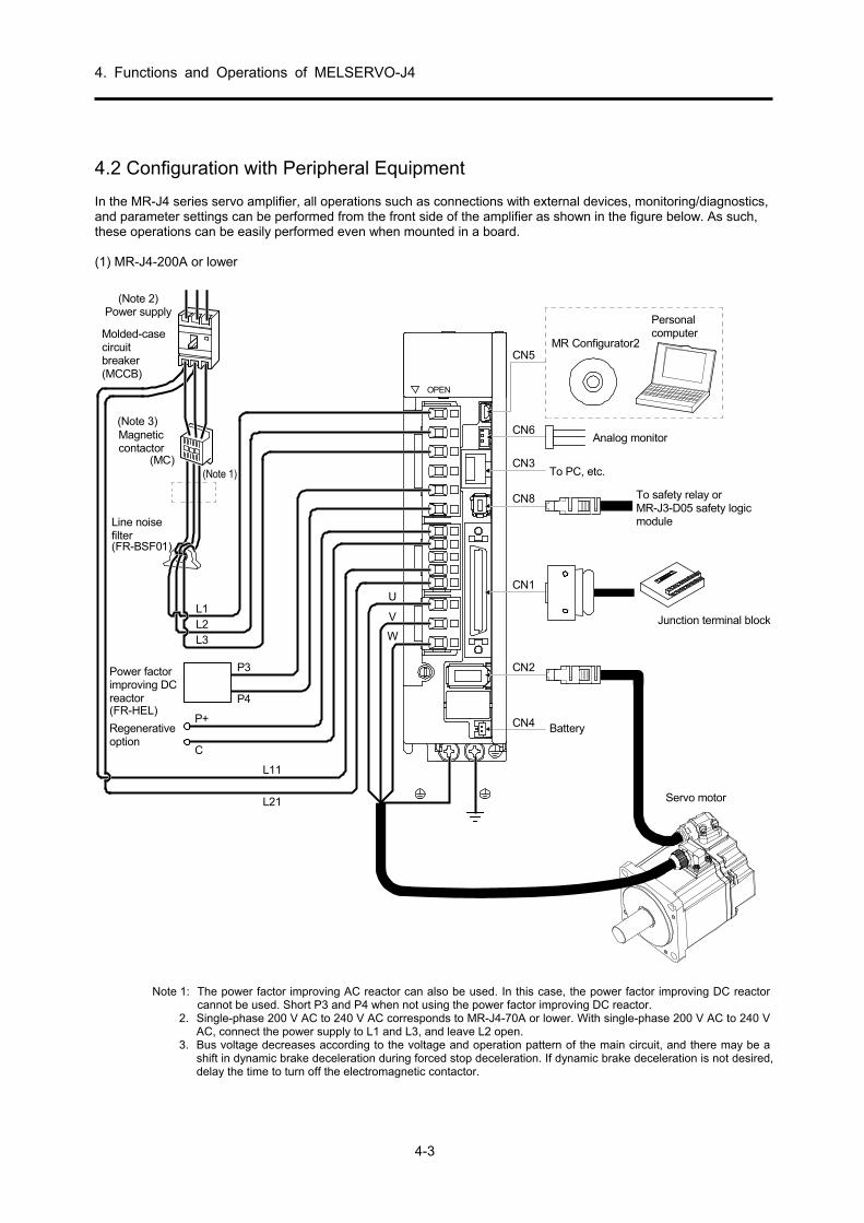
4. Functions and Operations of MELSERVO-J4
4-3
4.2 Configuration with Peripheral Equipment In the MR-J4 series servo amplifier, all operations such as connections with external devices, monitoring/diagnostics, and parameter settings can be performed from the front side of the amplifier as shown in the figure below. As such, these operations can be easily performed even when mounted in a board. (1) MR-J4-200A or lower
CN4
Line noisefilter(FR-BSF01)
CN5
Regenerativeoption
P+
C
L11
L21
P3
P4
Servo motor
Personalcomputer
MR Configurator2
CN3
CN6
CN8
CN1
CN2
W
V
U
Magneticcontactor
L1L2L3
(Note 3)
(Note 1)(MC)
Power factorimproving DCreactor(FR-HEL)
Molded-casecircuitbreaker(MCCB)
RS T
To safety relay orMR-J3-D05 safety logicmodule
Analog monitor
Junction terminal block
Power supply(Note 2)
Battery
To PC, etc.
OPEN
Note 1: The power factor improving AC reactor can also be used. In this case, the power factor improving DC reactor
cannot be used. Short P3 and P4 when not using the power factor improving DC reactor. 2. Single-phase 200 V AC to 240 V AC corresponds to MR-J4-70A or lower. With single-phase 200 V AC to 240 V
AC, connect the power supply to L1 and L3, and leave L2 open. 3. Bus voltage decreases according to the voltage and operation pattern of the main circuit, and there may be a
shift in dynamic brake deceleration during forced stop deceleration. If dynamic brake deceleration is not desired, delay the time to turn off the electromagnetic contactor.

4. Functions and Operations of MELSERVO-J4
4-4
(2) MR-J4-350A (example)
CN5
Personalcomputer
MR Configurator2
CN6
CN3
CN8
CN1
To safety relay orMR-J3-D05 safety logicmodule
Analog monitor
To PC, etc. (Note 4)
Junction terminal block
Line noisefilter(FR-BSF01)
Regenerativeoption
P+
C
L11
L21
P3
P4
Servo motor
CN2
W
VU
Magneticcontactor(MC)
L1L2L3
(Note 3)
(Note 1)
Power factorimprovingDC reactor(FR-HEL)
Power supply(Note 2)
CN4Battery
Molded-casecircuit breaker(MCCB)
RS T
Note 1: The power factor improving AC reactor can also be used. In this case, the power factor improving DC reactor
cannot be used. Short P3 and P4 when not using the power factor improving DC reactor. 2. For power supply specifications, refer to the MR-J4- servo amplifier instruction manual. 3. Bus voltage decreases according to the voltage and operation pattern of the main circuit, and there may be a
shift in dynamic brake deceleration during forced stop deceleration. If dynamic brake deceleration is not desired, delay the time to turn off the electromagnetic contactor.
4. The RS-422 communication function is compatible with Ver.A3 and later.

4. Functions and Operations of MELSERVO-J4
4-5
4.3 Operation after Installation
WARNING
Do not operate the switches with wet hands. Doing so may cause an electric shock.
CAUTION
Check the parameters before starting operation. Failure to do so may cause some machines to operate unexpectedly.
Since the radiator, regenerative resistor, servo motor, or other parts of the servo amplifier may reach high temperatures for some time during energization or after power-off, perform safety practices such as providing covers so that these parts are not touched or do not come into contact with other parts (cables, etc.) by mistake. Failure to do so may cause burn injuries or damage to parts.
Never touch the servo motor rotor while operating. Doing so may cause injury.
4.3.1 Startup Procedure
Wiring check Visually check whether the wires are correctly connected to theservo amplifier and the servo motor, or check using the DO forcedoutput function, etc.
Surrounding environment check Check the surrounding environment of the servo amplifier andservo motor.
Individual parameter settings Set the parameters as necessary, such as the control mode to beused and the regenerative option selection.
Test operation of just the servo motor in the test operation mode
For the test operation, with the servo motor disconnected from themachine and operated at as low a speed as possible, checkwhether the servo motor rotates correctly.
Test operation on just the servo motor according to commands
For the test operation, with the servo motor disconnected from themachine and operated at as low a speed as possible, sendcommands to the servo amplifier and check whether the servomotor rotates correctly.
Test operation with the servo motor and machine connected
After connecting the servo motor to the machine, check themotion of the machine by sending operation commands from thecontroller.
Gain adjustment Adjust the gain to optimize the machine motions.
Operation
Stop Stop giving commands and stop operation.
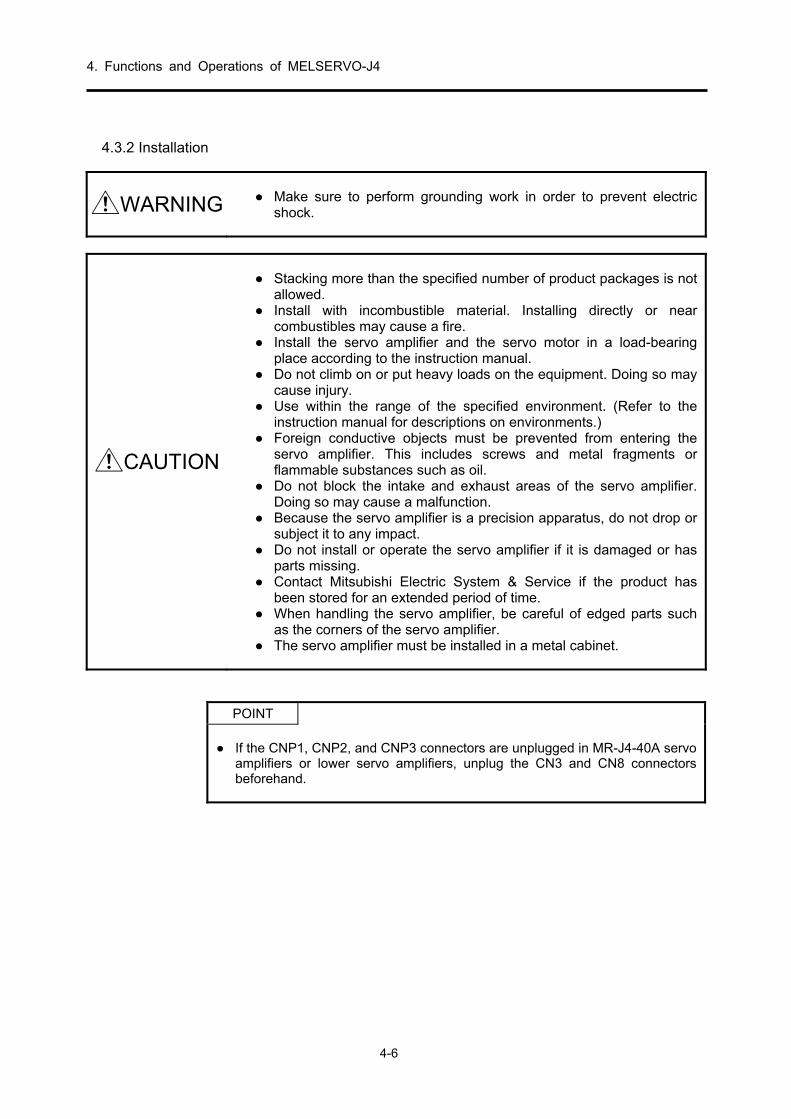
4. Functions and Operations of MELSERVO-J4
4-6
4.3.2 Installation
WARNING
Make sure to perform grounding work in order to prevent electric shock.
CAUTION
Stacking more than the specified number of product packages is not
allowed. Install with incombustible material. Installing directly or near
combustibles may cause a fire. Install the servo amplifier and the servo motor in a load-bearing
place according to the instruction manual. Do not climb on or put heavy loads on the equipment. Doing so may
cause injury. Use within the range of the specified environment. (Refer to the
instruction manual for descriptions on environments.) Foreign conductive objects must be prevented from entering the
servo amplifier. This includes screws and metal fragments or flammable substances such as oil.
Do not block the intake and exhaust areas of the servo amplifier. Doing so may cause a malfunction.
Because the servo amplifier is a precision apparatus, do not drop or subject it to any impact.
Do not install or operate the servo amplifier if it is damaged or has parts missing.
Contact Mitsubishi Electric System & Service if the product has been stored for an extended period of time.
When handling the servo amplifier, be careful of edged parts such as the corners of the servo amplifier.
The servo amplifier must be installed in a metal cabinet.
POINT
If the CNP1, CNP2, and CNP3 connectors are unplugged in MR-J4-40A servo
amplifiers or lower servo amplifiers, unplug the CN3 and CN8 connectors beforehand.

4. Functions and Operations of MELSERVO-J4
4-7
(1) Mounting direction and distance
CAUTION
The mounting direction must be correct. Doing so may cause a
malfunction. Secure the prescribed distance between the servo amplifier and the
inner surface of the cabinet or other devices. Doing so may cause a malfunction.
(a) 7 kW or lower (1) For single installations
40 mm or more
10 mm ormore
10 mm ormore
40 mm ormore
Servo amplifier
Cabinet Cabinet
80 mm or moreWiring margin
Ceiling
Ground
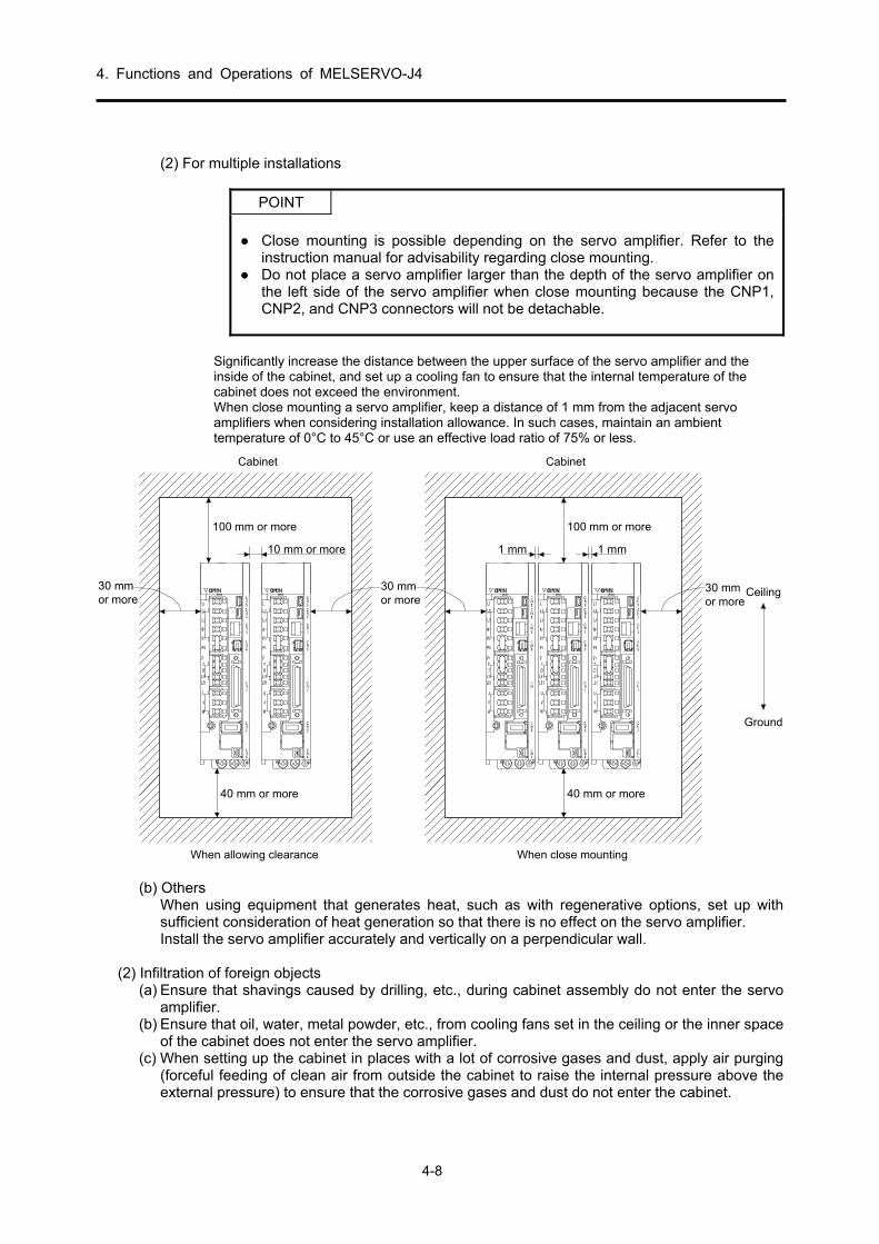
4. Functions and Operations of MELSERVO-J4
4-8
(2) For multiple installations
POINT
Close mounting is possible depending on the servo amplifier. Refer to the
instruction manual for advisability regarding close mounting. Do not place a servo amplifier larger than the depth of the servo amplifier on
the left side of the servo amplifier when close mounting because the CNP1, CNP2, and CNP3 connectors will not be detachable.
Significantly increase the distance between the upper surface of the servo amplifier and the inside of the cabinet, and set up a cooling fan to ensure that the internal temperature of the cabinet does not exceed the environment. When close mounting a servo amplifier, keep a distance of 1 mm from the adjacent servo amplifiers when considering installation allowance. In such cases, maintain an ambient temperature of 0°C to 45°C or use an effective load ratio of 75% or less.
100 mm or more
10 mm or more
30 mmor more
30 mmor more
40 mm or more
Cabinet
Ceiling
Ground
100 mm or more
1 mm
30 mmor more
40 mm or more
Cabinet
1 mm
When allowing clearance When close mounting
(b) Others When using equipment that generates heat, such as with regenerative options, set up with sufficient consideration of heat generation so that there is no effect on the servo amplifier. Install the servo amplifier accurately and vertically on a perpendicular wall.
(2) Infiltration of foreign objects
(a) Ensure that shavings caused by drilling, etc., during cabinet assembly do not enter the servo amplifier.
(b) Ensure that oil, water, metal powder, etc., from cooling fans set in the ceiling or the inner space of the cabinet does not enter the servo amplifier.
(c) When setting up the cabinet in places with a lot of corrosive gases and dust, apply air purging (forceful feeding of clean air from outside the cabinet to raise the internal pressure above the external pressure) to ensure that the corrosive gases and dust do not enter the cabinet.

4. Functions and Operations of MELSERVO-J4
4-9
(3) Mounting direction
(a) Standard servo motor The following table shows the mounting direction of a standard servo motor.
Servo motor series Mounting direction
HG-MR HG-KR HG-SR
Can be installed in all directions
When installing a servo motor horizontally, it is recommended that the connector part face downward. When installing vertically or diagonally, set up a connection cable and cable holder.
Cableholder
(b) Servo motor with electromagnetic brake A servo motor with an electromagnetic brake can also be installed in the same direction as a standard servo motor. When installed with the shaft upward, a sliding sound from the brake disk can occasionally be heard, but this is not a malfunction.
(c) Geared servo motor
The mounting direction of a geared servo motor changes depending on the type of reducer. Make sure to install in the specified direction. For details, refer to the servo motor instruction manual (vol. 3).

4. Functions and Operations of MELSERVO-J4
4-10
(4) Caution when removing and setting a load
CAUTION
Absolutely do not strike the shaft end with a hammer, etc., during
assembly. Doing so may damage the encoder.
(a) For servo motors with a key groove, use the screw hole at the end of the shaft to mount the pulley to the shaft. To install, first insert both screw bolts in the screw holes of the shaft, place the washer at the end of coupling, and tighten with a nut.
Pulley
Servo motor
Double-end stud
Nut
Washer
(b) For shafts without a key groove, use a friction coupling. (c) When extracting the pulley, ensure that there is not excessive load or shock on the shaft and
use a pulley remover. (d) Set up protective covers, etc., to ensure the safety of rotating parts such as pulleys installed on
the shaft. (e) When installing a pulley on the shaft, if the shaft end needs to be threaded, place a request
with Mitsubishi. (f) The direction of the encoder attached to the servo motor cannot be changed. (g) When installing the servo motor, tighten sufficiently with a spring washer, etc., so that the bolt
does not loosen due to vibration.

4. Functions and Operations of MELSERVO-J4
4-11
(5) Permissible load for the shaft
CAUTION
Do not use a rigid (solid body) coupling because it will apply an
excessive bend load on the shaft and there may be a possibility of bearing deterioration or servo motor axis breakage.
For the permissible load of a shaft specific to the servo motor, refer to the servo motor instruction manual (vol. 3).
(a) Use a flexible coupling, and ensure that shaft misalignment is less than the permissible radial
load of the shaft. (b) When using a pulley/sprocket and a timing belt, select ones that can fit in the permissible radial
load. (c) If the permissible load is exceeded, it may lead to bearing deterioration and shaft damage. (d) Loads shown in this section are one-way static loads, and eccentric loads are not included.
Eccentric loads should be as small as possible. Otherwise, servo motor damage may occur.
(6) Countermeasures against entry of oil Ensure that foreign particles such as oil do not mix inside of the servo motor shaft. When installing the servo motor, keep the items in this section in mind.
(a) Do not use cables soaked in oil.
Cover
Servomotor
Oil or water puddle
<Defect> Capillary action
(b) For shaft installation, ensure that there is no oil from the load side, gear box, etc.
Lubricating oil
Gear
Servo motor
(c) With oils such as cutting oil, there may be an influence on seal adhesion, packing, cables, etc., depending on the type of oil.
(d) Because there may be cases when use cannot be allowed in standard specification servo
motors in environments where there is usually oil mist and normal oil, grease, etc., inquire with Mitsubishi.

4. Functions and Operations of MELSERVO-J4
4-12
(7) Cable
Ensure that the cable does not move by fixing the power supply and encoder cable drawn out from the servo motor to the servo motor. Disconnection may occur. Also, do not make alterations to the connector, terminal, etc., at the end of the cable.
(8) Servo motor with oil seal For servo motors with an oil seal, oil penetration from outside the oil seal can be prevented. Install appropriately in accordance with this section. For servo motors with an oil seal, there may be a creaking sound from the oil seal when operating, but this is not a problem with the function. (a) Pressure/oil level
Install the servo motor horizontally, and ensure that the height (h) of the oil side of the gearbox is always lower than the lip. If the oil side is higher than the oil lip, oil will penetrate inside the servo motor, causing a malfunction.
GearServo motor
Oil seal
Shaft
Oil surface h
Lip
If pressure on the oil seal is strong, friction will increase and cause the life to decrease. Therefore, set up a suction hole in the gearbox so that the internal pressure of the gearbox does not increase, and ensure that the internal pressure is constant.
(b) Temperature
The life of the oil seal decreases if the lip temperature is high. The allowable temperature for the material used for the lip is 100°C, and because the lip will be subject to a temperature rise of 10°C to 15°C at maximum rotation, ensure that no high temperature oil is splashed on the lip.
(9) Encoder cable stress
(a) Sufficiently examine the clamping method of the cable and ensure that bending stress and
cable empty weight stress is not applied to the cable connection part. (b) When using in applications where the servo motor itself moves, fix the cable (detector, power
supply, brake) by gradually slackening from the connector so that there is no stress on the servo motor connector. Use the optional encoder cable within the bending life range. With cables for the power supply and brake wiring, use within the bending life range of the power supply used.
(c) Ensure that the cable casing is not cut by sharp chips, that it does not rub against the
mechanical radian, and that there is no chance of people or cars stepping on the cable. (d) When the servo motor is installed in a machine that moves, ensure that the bend radius is as
large as possible. Refer to the next page for the bending life.

4. Functions and Operations of MELSERVO-J4
4-13
(10) Cable bending life
The bending life of the cable is displayed. This graph is a calculated value. Because it is not a guaranteed value, in reality a little allowance should be provided.
1×10⁷
5×10⁷
1×10⁸
5×10⁶
1×10⁶
5×10⁵
1×10⁵
5×10⁴
1×10⁴
5×10³
1×10³
4 7 10 20 40 70 100 200
Bending radius [mm]
a: Long bending life encoder cableLong bending life motor power cableLong bending life motor brake cable
a
b
Num
ber
ofbe
nds
[num
ber
oftim
es]
b: Standard encoder cableStandard motor power cableStandard motor brake cable

4. Functions and Operations of MELSERVO-J4
4-14
4.3.3 Wiring System and Sequence (1) Power-on procedure
1) With the power supply wiring, make sure to use a magnetic contactor in the main circuit power supply (three-phase: L1/L2/L3; one-phase: L1/L3) as shown in section 4.2. Configure so that the magnetic contactor is turned off at the same time as an alarm is generated in the external sequence.
2) Turn on the control circuit power supply (L11/L21) at the same time or before turning on the main circuit
power supply. If the main circuit power supply is not turned on, a warning is displayed on the display. However, the warning disappears and operation returns to normal when the main circuit power supply is turned on.
3) The servo amplifier can receive SON (servo-on) signals 2.5 s to 3.5 s after the main circuit power supply
is turned on. Therefore, if SON (servo-on) is turned on at the same time as the main circuit power supply, the base circuit will be turned on after 2.5 s to 3.5 s. After approximately 5 ms, RD (Ready) is turned on and operation becomes available. (Refer to (3) in this section.)
4) When RES (reset) is turned on, the base circuit shuts off, and the servo motor shaft goes into a free state.

4. Functions and Operations of MELSERVO-J4
4-15
(2) Connection example
Wire the power supply and main circuit so that when an alarm occurrence is detected and the power supply is shut off, SON (servo-on) also turns off at the same time. Always connect a magnetic contactor between the power supply and the main circuit power supply (L1/L2/L3) of the servo amplifier in order to configure a power supply shut-off on the power supply side of the servo amplifier.
MC(Note 6)
ALM
DICOM
DOCOM
CN3
(Note 4)
DC24V
MalfunctionRA1
L1
L2
L3
Three-phase200 V to 240 V AC
Servo amplifier
P3
P4
P+
L11
L21
N-
D
C
U
V
W
(Note 1)(Note 9)
(Note 2)
CNP1
CNP3
PE
CNP2
Servo motor
U
V
WM
Motor
EncoderCN2(Note 3)Encoder
cable
(Note 5)
MalfunctionRA1
Off
MC
ONMC
SKEmergency stop switch
CN1
Forced stop 2
Servo-on(Note 4)
EM2
SON
DOCOM
CN8(Note 8)Short-circuit connector(Servo amplifier accessory)
(Note 7)Main circuit power supply
MCCB
Note 1. Make sure to connect between P3 and P4. (Wiring is complete when shipped) For harmonics countermeasures, refer to section 7.3.3 of this manual.
2. Make sure to connect between P+ and D. (Wiring is complete when shipped) 3. Use of the optional cable is recommended for the encoder cable.
For cable selection, refer to the servo motor instruction manual (vol. 3). 4. This is with a sink I/O interface. 5. For servo motor power cable connection, refer to the servo motor instruction manual (vol. 3). 6. Use an electromagnetic contactor with an operation delay time (interval between the current being applied to
the coil and closure of the contacts) of 80 ms or less. Bus voltage decreases according to the voltage and operation pattern of the main circuit, and there may be a shift in dynamic brake deceleration during forced stop deceleration. If dynamic brake deceleration is not desired, delay the time to turn off the electromagnetic contactor.
7. In order to prevent unexpected restarting of the servo amplifier, configure the circuit so that EM2 is also turned off when the main circuit power supply is turned off.
8. When not using the STO function, mount the short-circuit connector supplied with the servo amplifier. 9. If the wire used for L11 and L21 is thinner than the wire used for L1, L2, and L3, do not use a fuse breaker. 10. To avoid a malfunction, do not connect the U, V, W, and CN2 phase terminals of the servo amplifier to the
servo motor of an incorrect axis.
Power supply/main circuit wiring (three-phase 200 V AC to 240 V power supply for MR-J4-10A to MR-J4-350A)
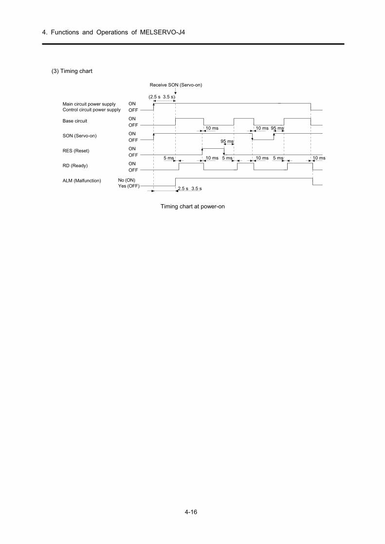
4. Functions and Operations of MELSERVO-J4
4-16
(3) Timing chart
95 ms
95 ms
RD (Ready)
RES (Reset)
SON (Servo-on)OFFON
OFFON
ONOFF
Base circuitOFFON
OFFON
10 ms5 ms
10 ms
10 ms5 ms
10 ms
5 ms 10 ms
(2.5 s 3.5 s)
Receive SON (Servo-on)
Main circuit power supplyControl circuit power supply
No (ON)ALM (Malfunction)
2.5 s 3.5 sYes (OFF)
Timing chart at power-on

4. Functions and Operations of MELSERVO-J4
4-17
(4) Timing chart at alarm generation
CAUTION
When an alarm occurs, remove the cause, verify that no operation
signal is input, secure safety, and resume operation after clearing the alarm.
POINT
In torque control mode, the forced stop deceleration function cannot be used.
When an alarm occurs in the servo amplifier, the base circuit is shut off, and the servo motor stops with dynamic braking. At the same time, shut off the main circuit power supply with an external sequence. Although the alarm can be cleared by turning the control circuit power supply OFF→ON, by pressing the "SET" button on the current alarm screen, or by OFF→ON of Reset (RES), the alarm cannot be truly cleared until the cause of the alarm is removed. (a) When using the forced stop deceleration function
POINT
This is for when [Pr. PA04] was set to "2 _ _ _" (initial value).
(1) When the forced stop deceleration function is enabled
Ignore command.
Alarm occurrence
Alarm No.No alarm
(Note)Model speed command=0and below zero speed
MBR(Electromagneticbrake interlock)
ON
OFF
ON (No)
OFF (Yes)
Base circuit(Supply energy toservo motor)
ON
OFF
Servo amplifier display
0 r/min
Servo motor speed
ALM (Malfunction)
Note: A model speed command is generated inside the servo amplifier for forced stop deceleration of the servo motor.
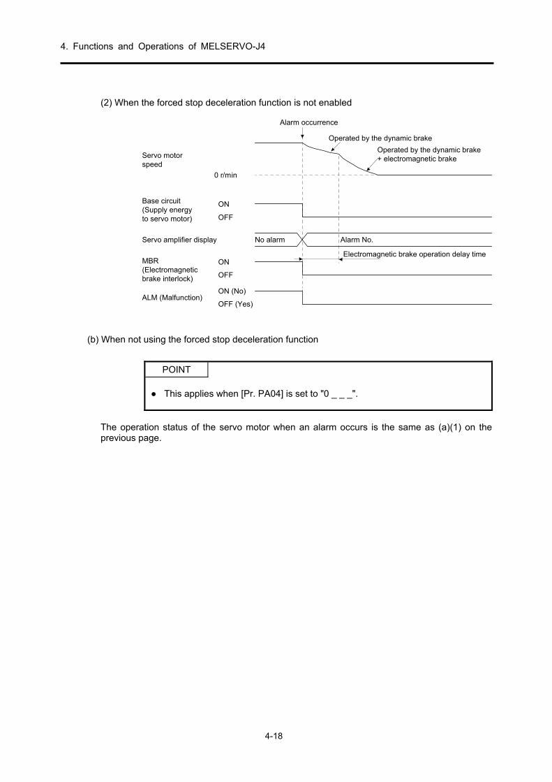
4. Functions and Operations of MELSERVO-J4
4-18
(2) When the forced stop deceleration function is not enabled
MBR(Electromagneticbrake interlock)
ON
OFF
ON (No)
OFF (Yes)
Base circuit(Supply energyto servo motor)
ON
OFF
Servo amplifier display
0 r/min
Servo motorspeed
ALM (Malfunction)
No alarm Alarm No.
Operated by the dynamic brake
Operated by the dynamic brake+ electromagnetic brake
Electromagnetic brake operation delay time
Alarm occurrence
(b) When not using the forced stop deceleration function
POINT
This applies when [Pr. PA04] is set to "0 _ _ _".
The operation status of the servo motor when an alarm occurs is the same as (a)(1) on the previous page.

4. Functions and Operations of MELSERVO-J4
4-19
(1) Regenerative error
If regenerative error (AL. 30) occurs and operation is performed by repeatedly clearing the alarm by turning the control circuit power supply OFF→ON, accidents may occur due to heat generation of the external regenerative resistor.
(2) Momentary power failure of the power supply
Undervoltage (AL.10) occurs when the input power supply is in the following states. The power failure of the control circuit power supply continues for 60 ms or more, and the control
circuit is not completely OFF. The bus voltage drops to 200 V DC or less for MR-J4-A and 380 V DC or less for MR-J4-A4.
(3) With position control mode (incremental)
When an alarm occurs, the home position disappears. When operation is restarted after clearing the alarm, execute home position return.

4. Functions and Operations of MELSERVO-J4
4-20
(5) Interface internal connection figure
3
DOCOM
SON SON SONCN115
SP2 SP2 16PC ST1 RS2 17TL ST2 RS1 18
RES RES 19CR SP1 41
EM2 42LSP 43LSN 44LOP 45
46OPC 12
2047
PP 10PG 11NP 35NG 36
LSPLSNLOP
DICOMDOCOM
LOP
RESSP1
P T CN1
21
22
23
24
25
48
49
DICOM
INP SA
ZSP
INP
TLC
RD
ZSP
TLC
ALM
RD
ZSP
TLC
RD
SA
P S
CN1 P S T4567893334
543617
CN3 P S T
LALARLB
LBRLZ
LZROPLG
SDPSDNRDPRDNLGLG
CN6 P S T
MO1
MO2
LG
3
2
1
Differential linedriver output(35 mA or lower)
Open collectoroutput
Approx. 100 Ω
Approx. 100 Ω
CN1P T
2VC VLA
27TLA TLA TC
1P15
3LG28LG30LG
ケースSD
(Note 2)
It is isolated.
DC15V
Approx.6.2 kΩ
Approx.6.2 kΩ
RS-422
Analog monitor
Servo amplifier
24V DC
CN2 P S T
24
78
MRMRR
MDMDR
LG
Encoder
E
Servo motor
(Note 3)(Note 3)
USB
P T
D+GND
VBUSD-
1235
CN5
(Note 1)
(Note 1)
(Note 1)
(Note 1)
(Note 1)
(Note 1)
(Note 1)
(Note 1)
±10 V DC±10 V DC
RA
RA
M
TS
S
S
Approx. 1.2 kΩ
Approx. 1.2 kΩ
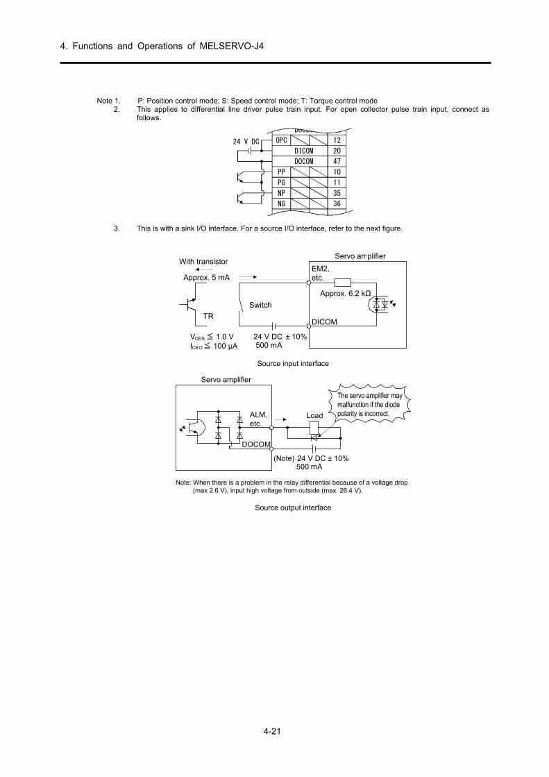
4. Functions and Operations of MELSERVO-J4
4-21
Note 1. P: Position control mode; S: Speed control mode; T: Torque control mode
2. This applies to differential line driver pulse train input. For open collector pulse train input, connect as follows.
DOCOM 46
OPC 12
20
47
PP 10
PG 11
NP 35
NG 36
DICOM
DOCOM
24 V DC
3. This is with a sink I/O interface. For a source I/O interface, refer to the next figure.
Approx. 6.2 kΩ
Approx. 5 mA
TR
24 V DC ± 10%500 mA
Switch
With transistorEM2,etc.
Servo amplifier
DICOM
VCES ≦ 1.0 VICEO≦ 100 µA
Source input interface
(Note) 24 V DC ± 10%500 mA
The servo amplifier maymalfunction if the diodepolarity is incorrect.
Servo amplifier
ALM,etc.
Load
DOCOM
Note: When there is a problem in the relay differential because of a voltage drop(max 2.6 V), input high voltage from outside (max. 26.4 V).
Source output interface

4. Functions and Operations of MELSERVO-J4
4-22
4.3.4 Standard Connection Figure (1) Position control
(1) Connection of all I/O signals
(Note 12)
Plate
Plate
Servo amplifier
2 m or lower
3 MO1
2 MO2
(Note 7)CN6
± DC10 V
Analog monitor 1
Analog monitor 2
Malfunction (Note 6)
Zero speed detection
Limiting torque
Encoder phase A pulse(Differential line driver)
21 DICOM
48 ALM
23 ZSP
25 TLC
24 INP
4 LA5 LAR
7 LBR
34 LG33 OP
SD
10 m or lower
2 m or lower
Control common
Encoder phase Z pulse(Open collector)
(Note 7)CN1
LG
DICOM
10 m or lower (Note 8)
41
2046
49101135
93
36
CLEARCOM
12
1516
1413
11
CLEARRDYCOMREADY
PULSE F+PULSE F-
PG0PG0 COM
PULSE R+PULSE R- 18
10
17
9
DOCOM
CR
RDPPPGNPNGLZ
LZR8
(Note 11)
(Note 7)(Note 2)CN1
Positioning moduleQD75D
24 V DC (Notes 4 and 12)
In-position
Control commonSD
RA1
RA2
RA3
RA4
Plate
(Note 1)
2 m or lower
10 m or lower
Upper limit setting
4215191718434447127
SD
EM2SONRESPCTL
LSPLSN
DOCOM
P15RTLALG 28
(Note 7)CN1
Forced stop 2Servo-onResetProportional controlExternal torque limit selectionForward rotation stroke endReverse rotation stroke end
(Note 3 and 5)
(Note 5)
+
(Note 10)USB cable(Optional)
(Note 9)MR Configurator2
CN5
CN8
Analog torque limit+10 V/max. torque
Personalcomputer
(Note 12)
(Note 13)Short-circuit connector(Servo amplifier accessory)
(Note 14) Main circuit power
LB
1 LG
supply
Encoder phase B pulse(Differential line driver)
± DC10 V
Connection I at the time of position control

4. Functions and Operations of MELSERVO-J4
4-23
Note 1. To prevent electric shock, always connect the protective earth (PE) terminal (marked with ) of the servo
amplifier to the protective earth (PE) of the cabinet. 2. Do not mistake the diode direction. If connected the other way round, the servo amplifier will malfunction and
no signal will be output. Also, the protection circuits of EM2 (forced stop 2), etc., may not operate. 3. At the time of operation, make sure to turn on EM2 (forced stop 2). (Normally closed contact) 4. Supply a power supply of 24 V DC ± 10% 500 mA from outside for the interface. 500 mA is the value when all
I/O signals are used. The current capacity can be lowered by reducing the number of I/O points. 5. At the time of operation, make sure to turn on EM2 (forced stop 2), LSP (forward rotation stroke end), and
LSN (reverse rotation stroke end). (Normally closed contact) 6. ALM (malfunction) is on when normal and no alarm is generated. When turned off (when an alarm is
generated), stop the programmable controller signal with a sequence program. 7. A signal with the same name is connected inside the servo amplifier. 8. Command pulse train input is for differential line driver types. Open-collector types are 2 m or less. 9. Use SW1DNC-MRC2-J. 10. The personal computer can also be connected using RS-422 communication of the CN3 connector. However,
the USB communication function (CN5 connector) and the RS-422 communication function (CN3 connector) are exclusive functions. Simultaneous use is not possible.
Personalcomputer RS-232C/RS-422 conversion cable
Recommended part: Interface cableDSV-CABV (Diatrend)
To RS-232 C connector
CN3
Servo amplifier
11. This connection is not required for QD75D. However, depending on the positioning module used, a connection between the control common and the LG of the servo amplifier is recommended to improve noise tolerance.
12. This is with a sink I/O interface. 13. When not using the STO function, mount the short-circuit connector supplied with the servo amplifier. 14. In order to prevent unexpected restarting of the servo amplifier, configure the circuit so that EM2 is also turned
off when the main circuit power supply is turned off.

4. Functions and Operations of MELSERVO-J4
4-24
(2) Connection of minimum required I/O signals
Connections below the minimum are required to move the motor. Connection of the output signal is not required. 1) Servo-on: Because this signal is used to start the main circuit, it absolutely
must be turned on before operation. When turned on, the servo-lock state is initiated.
2) Forward/reverse rotation stroke end: Connect to the limit switch on the normal load side. When turned off, movement is not possible in that direction. Movement will be in the reverse direction. If a load side limit switch such as a roll feed does not exist, always short-circuit between the DOCOM.
3) Forward/reverse pulse train: When a pulse train is input, the motor moves according to the pulse frequency/count. When not input, the motor stops and there is servo-lock.
4) Reset: Used to clear the alarm. Because an alarm can be cleared even when the control circuit power supply is off, this signal is not absolutely necessary.
Moreover, when the reset signal is on, servo-lock is cleared and the motor is freed.
5) Emergency stop: During operation, make sure to short-circuit the emergency stop signal (EMG) with the DOCOM using the emergency stop switch (normally closed contact).
24 V DC power supply
Servo amplifier
Forward run pulse train
Reverse run pulse train
Servomotor
Emergency stop
Servo-onReset
Forward rotation stroke end
Reverse rotation stroke end
Plate
Connection I at the time of position control

4. Functions and Operations of MELSERVO-J4
4-25
(3) Connection of minimum required I/O signals when operating with QD75
1) Servo-on 2) Forward/reverse rotation stroke end 3) Forward/reverse pulse train: Connect with the QD75 terminal as shown in the following figure. 4) Reset 5) Clear: Used to clear the counter when returning to the home position. 6) Zero pulse: Used as the home position signal when returning to the home position. 7) Ready: The servo-on state is output to the QD75, and it is used as an interlock signal. 8) Emergency stop: During operation, make sure to short-circuit the emergency stop signal (EMG) with
DOCOM using the emergency stop switch (normally closed contact).
Reset
Servo-onEmergency stop
Reverse rotation stroke end
Forward rotation stroke end
42
15
19
17
18
43
44
47
EMG
SON
RES
PC
TL
LSP
LSN
DOCOM
CN1CN2 Encoder cable
Servo motor
Servo amplifier
LG
DICOM
10 m or lower
41
20
46
49
10
11
35
9
3
36
CLEARCOM
12
15
16
14
13
11
CLEAR
RDYCOM
REDY
PULSE F+
PULSE F-
PG05
PG0 COM
PULSE R+
PULSE R- 18
10
17
9
DOCOM
CR
RD
PP
PG
NP
NG
LZ
LZR
8
CN1QD75D
Positioning module +
-
24 V DCpowersupply
To QD75Dcommon terminal
* For details on connections related to Q75, refer to the QD75 manual.
Connection III at the time of position control

4. Functions and Operations of MELSERVO-J4
4-26
[Supplementary explanation]
(1) Pulse train input types Generally, the command pulse inputs the forward/reverse rotation pulse train by an open-collector type or a differential system, which is suitable even for FX2N-20GM/10GM/10PG/1PG, QD75P/QD75D, and QD70P. With MR-J4 Series amplifiers, compatibility with the following pulse trains when switching parameters is also enabled in order to enable compatibility with pulse trains of various other command modules.
1) Types of pulse train forms
Parameter No. PA13
setting value Pulse train type
Upon forward rotation command
Upon reverse rotation command
Remarks
0010h
Neg
ativ
e lo
gic
Forward rotation pulse train
Reverse rotation pulse train
NP
PPQD75P, QD75D, QD70P FX2N-20GM/10GM/10PG/1PG(Setting value at shipping)
0011h Pulse train + code
PP
L HNP
QD75P, QD75D, QD70P, FX2N-20GM/10GM/10PG/1PG
0012h
Phase A pulse train
Phase B pulse train
PP
NP
QD75P, QD75D
0000h
Pos
itive
logi
c
Forward rotation pulse train
Reverse rotation pulse train NP
PP
QD75P, QD75D, QD70P
0001h Pulse train + code LH
PP
NPQD75P, QD75D, QD70P
0002h
Phase A pulse train
Phase B pulse train
PP
NPQD75P, QD75D
Note: An or arrow in the table indicates the import timing of the pulse train.

4. Functions and Operations of MELSERVO-J4
4-27
2) Types of hardware The following configurations can be selected depending on the hardware of command module.
Servo amplifier
Servo amplifier
Approx.1.2 kΩ
Approx.1.2 kΩ
DOCOM
OPC
PP
24 V DC
NP
SD
PP
NP
SD
(注)
(Note)
Note:
Approx. 100 Ω
PG
NG
The pulse train input interface uses a photocoupler. Becauseof this, it is not usually operated as the current decreaseswhen the resistor is connected to the pulse train signal line.
Note: The pulse train input interface uses a photocoupler. Becauseof this, it is not usually operated as the current decreaseswhen the resistor is connected to the pulse train signal line.
Approx. 100 Ω
(a) Open-collector type (b) Differential line driver type
(2) Torque limit
When parameter number PA11 (Forward rotation torque limit) and parameter number PA12 (Reverse rotation torque limit) are set, the maximum torque is always limited during operation.
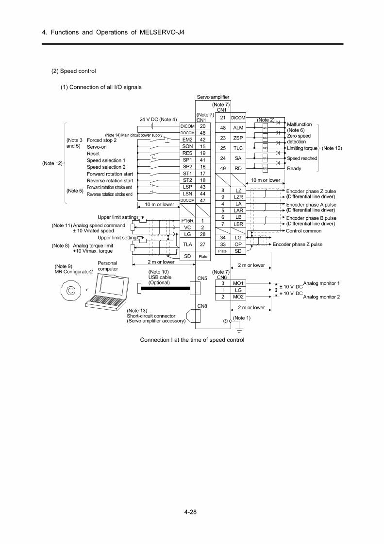
4. Functions and Operations of MELSERVO-J4
4-28
(2) Speed control
(1) Connection of all I/O signals
(Note 14) Main circuit power supply
CN8(Note 13)Short-circuit connector(Servo amplifier accessory)
(Note 1)
(Note 2)
(Note 7)CN1
(Note 7)CN1
Plate
Servo amplifier
(Note 7)CN6
2 m or lower
3 MO1
2 MO2
21 DICOM
48 ALM
23 ZSP
25 TLC
24 SA
49 RD
(5 LAR
7 LBR
34 LG33 OP
SD
2 m or lower
(9 LZR
2046
DICOM
DOCOM
10 m or lower
21
2 m or lower
Upper limit setting28
27
Plate
Upper limit setting
VC
SD
TLA
LG
P15R
+
(Note 10)USB cable(Optional)
CN5
(Note 11) Analog speed command± 10 V/rated speed
(Note 8) Analog torque limit+10 V/max. torque
(Note 9)MR Configurator2
Personalcomputer
24 V DC (Note 4)
RA1
RA2
RA3
RA4
RA5
421519
1718434447
4116
EM2SONRES
ST1ST2LSPLSN
DOCOM
SP1SP2
Reverse rotation stroke end
Forced stop 2Servo-onResetSpeed selection 1
Forward rotation startSpeed selection 2
Reverse rotation startForward rotation stroke end
(Note 3and 5)
(Note 5)
(Note 12)
DC± 10 VDC± 10 V
Analog monitor 1
Analog monitor 2
Encoder phase A pulse(Differential line driver)
Encoder phase B pulse(Differential line driver)
Control common
Encoder phase Z pulse
Encoder phase Z pulse(Differential line driver)
(Note 12)
Malfunction(Note 6)Zero speeddetectionLimiting torque
Speed reached
Ready
10 m or lower
8 LZ
4
6
LA
LB
1 LG
Connection I at the time of speed control

4. Functions and Operations of MELSERVO-J4
4-29
Note 1. To prevent electric shock, always connect the protective earth (PE) terminal (marked with ) of the servo
amplifier to the protective earth (PE) of the cabinet. 2. Do not mistake the diode direction. If connected the other way round, the servo amplifier will malfunction and
no signal will be output. Also, the protection circuits of EM2 (forced stop 2), etc., may not operate. 3. At the time of operation, make sure to turn on EM2 (forced stop 2). (Normally closed contact) 4. Supply a power supply of 24 V DC ± 10% 500 mA from outside for the interface. 500 mA is the value when all
I/O signals are used. The current capacity can be lowered by reducing the number of I/O points. 5. At the time of operation, make sure to turn on EM2 (forced stop 2), LSP (forward rotation stroke end), and
LSN (reverse rotation stroke end). (Normally closed contact) 6. ALM (malfunction) is on when normal and no alarm is generated. 7. A signal with the same name is connected inside the servo amplifier. 8. If use of TL (external torque limit selection) is enabled in [Pr.PD03] to [Pr.PD22], TLA can be used. 9. Use SW1DNC-MRC2-J. 10. The personal computer can also be connected using RS-422 communication of the CN3 connector. However,
the USB communication function (CN5 connector) and the RS-422 communication function (CN3 connector) are exclusive functions. Simultaneous use is not possible.
RS-232C/RS-422 conversion cable
CN3
Personalcomputer
Recommended part: Interface cableDSV-CABV (Diatrend)
To RS-232 C connector
Servo amplifier
11. When a minus voltage is input, use an external power supply. 12. This is with a sink I/O interface. 13. When not using the STO function, mount the short-circuit connector supplied with the servo amplifier. 14. In order to prevent unexpected restarting of the servo amplifier, configure the circuit so that EM2 is also
turned off when the main circuit power supply is turned off.

4. Functions and Operations of MELSERVO-J4
4-30
(2) Connection of minimum required I/O signals
Connections below the minimum are required to move the motor. Connection of the output signal is not required. 1) Servo-on: Because this signal is used to start the main circuit, it absolutely must be turned on before
operation.
When turned on, the servo-lock state is initiated. 2) Speed selection 1, 2: Select whether the speed command is the parameter setting value or the
external analog setting value.
The following figure shows an external analog speed command. 3) Forward rotation/reverse rotation start: Used as a start signal. 4) Reset: Used to clear the alarm. Because an alarm can be cleared even when the control circuit power
supply is off, this signal is not absolutely necessary.
Moreover, when the reset signal is on, servo-lock is cleared and the motor is freed. 5) Emergency stop: During operation, make sure to short-circuit the emergency stop signal (EMG) with
DOCOM using the emergency stop switch (normally closed contact).
24 V DCpowersupply
Servo amplifier
Emergency stop
Servo-onReset
Speed selection 1
Speed selection 2Forward rotation start
Reverse rotation startForward rotation stroke end
Reverse rotation stroke end
Analog speed command±10 V/rated speed
10 m or lower
Servomotor
Plate
Upper limit setting
Connection II at the time of speed control

4. Functions and Operations of MELSERVO-J4
4-31
[Supplementary explanation] External connection of speed command
(a) Speed selection 1 (SP1)/Speed selection 2 (SP2) and speed command value
The rotation speed settings according to internal speed commands 1 to 3 using speed selection 1 (SP1)/speed selection 2 (SP2) and the rotation speed settings according to analog speed command (VC) are selected as shown in the following table.
Note: External input signal
Rotation speed command value SP2 SP1
0 0 Analog speed command (VC)
0 1 Internal speed command 1 (Parameter number PC05)
1 0 Internal speed command 2 (Parameter number PC06)
1 1 Internal speed command 3 (Parameter number PC07)
Note. 0: OFF 1: ON
(b) Forward rotation start (ST1)/Reverse rotation start (ST2)
Forward rotation start (ST1)/reverse rotation start (ST2) are used to start and stop the motor. When both ST1 and ST2 are OFF or ON, there is deceleration stop and the servo-lock state is entered. If speed setting is done by an external analog voltage, the relation between the motor rotation direction and the voltage polarity start signal is as shown in the following table.
Forward rotation (CCW)
Reverse rotation (CW)
(Note 1) Input device (Note 2) Rotation direction
ST2 ST1 VC (Analog speed command) Internal speed
command + polarity 0V - polarity
0 0 Stop
(servo-lock) Stop
(servo-lock) Stop
(servo-lock) Stop
(servo-lock)0 1 CCW Stop
(no servo-lock) CW CCW
1 0 CW CCW CW
1 1 Stop
(servo-lock) Stop
(servo-lock) Stop
(servo-lock) Stop
(servo-lock) Note 1. 0: Off
1: On 2. When the torque limit is cleared during servo-lock, the servo motor may rotate rapidly depending on the position
deviation amount for the command position.

4. Functions and Operations of MELSERVO-J4
4-32
(c) External wiring example
The external connection of the speed command is displayed according to the external analog voltage. (1) When the polarity of the analog voltage is operated in forward/reverse only with
Japanese resistorRRS10 equivalent
ST2
DOCOM
P15R
VC
LG
SD
2 kΩ 2 kΩ
Servo amplifier
ST1
Reverse rotation
Forward rotation
-10V +10V
Rated speed
(2000 r/min)
Rated speed(2000 r/min)
ST10N
ST20N
External connection I of speed command
(d) Torque limit When parameter number PA11 (Forward rotation torque limit) and parameter number PA12 (Reverse rotation torque limit) are set, the maximum torque is always limited during operation.

4. Functions and Operations of MELSERVO-J4
4-33
(3) Torque control
(1) Connection of all I/O signals
24 V DC (Note 4)
Servo amplifier
(Note 6)CN6
2 m or lower
3 MO1
2 MO2
DC± 10 VDC± 10 V
Analog monitor 1
(Note 1)
9
(Note 2)
Malfunction(Note 5)Zero speeddetectionLimitingspeed
21 DICOM
48 ALM
23 ZSP
25 VLC
5 LAR
7 LBR
34 LG33 OP
SD
10 m or lower
2 m or lower
Control common
Encoder phase Z pulse(Open collector)
(Note 6)CN1
49 RD Ready
Encoder phase Z pulse(Differential line driver)LZR
(Note 6)CN1
2046
DICOM
DOCOM
Personal computer
+
(Note 8) USB cable(Optional)
CN5
27
1
2 m or lower
Upper limit setting28
2
Plate
Upper limit setting
TC
SD
VLA
LG
P15RAnalog torque command±8 V/max. torque
(Note 9) Analog speed limit0 to ±10 V/rated speed
(Note 7)MR Configurator2
(Note 10)
Plate
(Note 10)
10 m or lower
4215
19
1718
47
Forced stop 2Servo-on
Reset
Forward rotation startReverse rotation start
(Note 3)
4116Speed selection 2
EM2SON
RES
RS1RS2
DOCOM
SP1SP2
Speed selection 1
RA1
RA2
RA3
RA4
(Note 11)Short-circuit connector(Servo amplifier accessory)
CN8
(Note 12) Main circuit power supply
8
6
4
1
LZ
LA
LB
LG
Encoder phase A pulse(Differential line driver)
Encoder phase B pulse(Differential line driver)
Analog monitor 2
Torque control connection

4. Functions and Operations of MELSERVO-J4
4-34
Note 1. To prevent electric shock, always connect the protective earth (PE) terminal (marked with ) of the servo
amplifier to the protective earth (PE) of the cabinet. 2. Do not mistake the diode direction. If connected the other way round, the servo amplifier will malfunction and
no signal will be output. Also, the protection circuits of EM2 (forced stop 2), etc., may not operate. 3. At the time of operation, make sure to turn on EM2 (forced stop 2). (Normally closed contact) 4. Supply a power supply of 24 V DC ± 10% 500 mA from outside for the interface. 500 mA is the value when all
I/O signals are used. The current capacity can be lowered by reducing the number of I/O points. 5. ALM (malfunction) is on when normal and no alarm is generated. 6. A signal with the same name is connected inside the servo amplifier. 7. Use SW1DNC-MRC2-J. 8. The personal computer can also be connected using RS-422 communication of the CN3 connector. However,
the USB communication function (CN5 connector) and the RS-422 communication function (CN3 connector) are exclusive functions. Simultaneous use is not possible.
Personalcomputer RS-232C/RS-422 conversion cable
Recommended part: Interface cableDSV-CABV (Diatrend)
To RS-232 C connector
CN3
Servo amplifier
9. When a minus voltage is input, use an external power supply. 10. This is with a sink I/O interface. 11. When not using the STO function, mount the short-circuit connector supplied with the servo amplifier. 12. In order to prevent unexpected restarting of the servo amplifier, configure the circuit so that EM2 is also
turned off when the main circuit power supply is turned off.

4. Functions and Operations of MELSERVO-J4
4-35
[Supplementary explanation] (1) External connection of torque control
a. Torque command and generated torque The relationship between the applied voltage of the analog torque command (TC) and the generated torque of the servo motor is shown in the figure on the left. The output torque command value corresponding to the voltage may have a difference of approximately 5% depending on the product. Moreover, if the voltage is -0.05 to +0.05 V, the generated torque may change. A torque generation direction dependant on forward rotation selection (RS1)/reverse rotation selection (RS2) when an analog torque command (TC) is used is shown in Table 4.1.
Table 4.1 Torque generation direction
Between RS1 and DOCOM
Between RS2 and DOCOM
Rotation direction
+ polarity 0 V - polarity
Open Open No torque
No torque
No torque
Short-circuit
Open
CCW (forward rotation power drive / reverse
rotation regenerative
driving)
CW (reverse rotation power drive/forward
rotation regenerative
drive)
Open Short-circuit
CW (reverse rotation power drive/forward
rotation regenerative
drive)
CCW (forward rotation power drive/reverse
rotation regenerative
drive)
Short-circuit
Short-circuit
No torque No torque
TC applied voltage [V]
Maximumtorque
Tor
que
0 +8 (-8)
Parameter number PC38Offset range-999 to +999 mV
Connection example Analog torque command offset range
(2) Torque limit When parameter number PA11 (Forward rotation torque limit) and parameter number PA12 (Reverse rotation torque limit) are set, the maximum torque is always limited during operation. The relationship between the generated torque of the servo motor and the limit value is the same as (1) mentioned above. However, an analog torque limit (TLA) cannot be used.
b. Connection figure Connect according to the following figure.
c. Analog torque command offset An offset voltage of -999 to 999 mV as shown in the next figure can be added to the TC applied voltage with parameter number PC38.
-8
CCW direction
+0. 05+8TC applied voltage [V]
CW directionMaximum torque
-0. 05
Generatedtorque
Maximum torque
Forward rotation (CCW)
Reverse rotation (CW)
Servo amplifier
RS1
RS2
SG
TC
LG
SD
-8 to+8V
ボ プ
DOCOM
Torque control level (when RS1: ON)

4. Functions and Operations of MELSERVO-J4
4-36
(3) Speed limit a. Speed limit value and rotation speed
Limits the rotation speed set in parameter number PC05 to PC11 (internal speed limit 1 to 7) or the rotation speed set by the applied voltage of the analog speed limit (VLA). The relationship between the applied voltage of the analog speed limit (VLA) and the servo motor speed is shown in the figure on the left. A limit direction according to forward rotation selection (RS1)/reverse rotation selection (RS2) is shown in Table 4.2.
Table 4.2 RS1/RS2 and speed limit direction
Between RS1 and DOCOM
Between RS2 and DOCOM
Speed limit direction
Analog speed limit (VLA)
Internal speed limit
+ polarity - polarity 1 to 3
Short-circuit
Open CCW CW CCW
Open Short-circuit
CW CCW CW
VLA applied voltage and rotation speed (when RS1: ON)
b. Connection figure Generally, connect according to the following figure.
Servo amplifier
P15R
VLA
LG
SD
1 kΩ2 kΩ
Japanese resistorRRS10 equivalent
DOCOM
SP2
SP1
Connection example 1
Torque limit and torque control Because the generated torque of the motor is proportional to a current, the generated torque of the motor can be freely controlled by controlling the current of the AC servo motor. Usually, although an AC servo motor (synchronous type) has a maximum torque of 300% or more, when controlling the position and speed, controlling so that no torque is generated above a certain value is known as "torque limit". On the other hand, controlling so that the generated torque of motor is always maintained constantly at a certain value is known as "torque control". Torque limiting is used to control power during pressing operations, reducer protection, etc., and control is performed so that no more than the required power is applied to a load or machine. Torque control is used when the power on the material (tension) is kept constant even if the speed changes due to a winding device, etc., and the speed depends on the generated torque and load torque.
Rotationspeed[r/min]
-10
Rated speed
CCW direction
0 +10VLA applied voltage [V]CW
direction
Rated speed
Forward rotation (CCW)
Reverse rotation (CW)

4. Functions and Operations of MELSERVO-J4
4-37
c. Speed selection 1 (SP1)/speed selection 2 (SP2)/speed selection (SP3) and speed command value The rotation speed settings according to internal speed commands 1 to 3 using speed selection 1 (SP1)/speed selection 2 (SP2)/speed selection 3(SP3) and the rotation speed settings according to analog speed limit (VLA) are selected as shown in Table 4.3. In the factory settings for MR-J4-A servo amplifiers, speed selection 3 (SP3) is not assigned to an external input signal. Internal speed commands 4 to 7 can be used when speed selection 3 (SP3) is assigned to a connector CN1 pin as external input signals by parameter number PD03 to PD12. However, with this training machine, because assigning speed selection 3 (SP3) and selecting using a switch is not possible, internal speed commands 4 to 7 cannot be used. If the speed is commanded by internal speed commands 1 to 7, the speed will not change according to the ambient temperature.
Table 4.3 SP1/SP2/SP3 and speed command value
d. During speed limit (VLC)
When the servo motor speed reaches the rotation speed limited by internal speed limit 1 to 7 or the analog speed limit, there is conduction between VLC and DICOM.
Input signal(Note) Speed command
SP3 SP2 SP1
0 0 0 Analog speed limit (VLA)
0 0 1 Internal speed limit 1 (Parameter number PC05)
0 1 0 Internal speed limit 2 (Parameter number PC06)
0 1 1 Internal speed limit 3 (Parameter number PC07)
1 0 0 Internal speed limit 4 (Parameter number PC08)
1 0 1 Internal speed limit 5 (Parameter number PC09)
1 1 0 Internal speed limit 6 (Parameter number PC10)
1 1 1 Internal speed limit 7 (Parameter number PC11)
Note. 0: OFF between DOCOMs (open) 1: ON between DOCOMs (short-circuit)

4. Functions and Operations of MELSERVO-J4
4-38
4.3.5 Power-On (1) Confirmation
Confirm the installation and the wiring performed in 4.3.2 and 4.3.3 again thoroughly before power-on. (a) Installation: Confirm the installation status based on section 4.3.2. Especially check for influences on the
amplifier ambient temperature from the heating element in the panel, for contact between the heating element and the cables, and check the waterproof/oil-proof measures of the servo motor.
(b) Wiring: Check the wiring based on section 4.3.3. Because an error in main circuit connections may also lead to module damage, a thorough check is especially required.
Although the main items are listed below, there may be other model-specific problems. For details, refer to the respective installation guides and instruction manuals.
(2) Wiring
Perform the following checks before operation. (a) Wiring of power supply system
Check the following items before turning on the main circuit or control circuit power supply.
1) Wiring of power supply system The power supply supplied to the power input terminals (L1, L2, L3, L11, L21) of the servo amplifier should meet the regulated specifications.
2) Servo amplifier/servo motor connection The phases of the servo motor power terminals (U, V, W) of the servo amplifier and the power
input terminals (U, V, W) of the servo motor should match. Servo amplifier Servo motor
M
U
V
W
U
V
W
The power supply supplied to the servo amplifier should not be connected to a servo motor power
terminal (U, V, W). A connected servo amplifier or servo motor has malfunctioned. Servo amplifier Servo motor
U V W
U V W
M
The ground terminal of the servo motor should be connected to the PE terminal of the servo
amplifier. Servo amplifier Servo motor
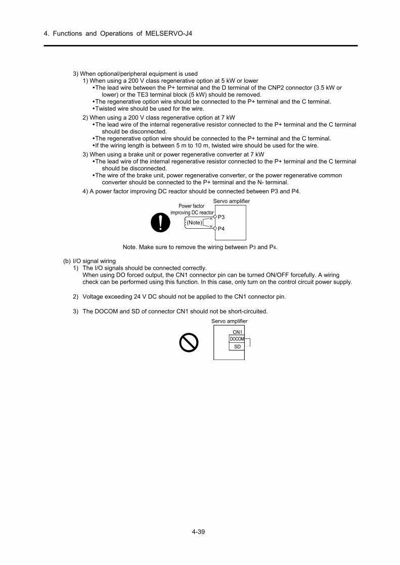
4. Functions and Operations of MELSERVO-J4
4-39
3) When optional/peripheral equipment is used
1) When using a 200 V class regenerative option at 5 kW or lower The lead wire between the P+ terminal and the D terminal of the CNP2 connector (3.5 kW or
lower) or the TE3 terminal block (5 kW) should be removed. The regenerative option wire should be connected to the P+ terminal and the C terminal. Twisted wire should be used for the wire.
2) When using a 200 V class regenerative option at 7 kW The lead wire of the internal regenerative resistor connected to the P+ terminal and the C terminal
should be disconnected. The regenerative option wire should be connected to the P+ terminal and the C terminal. If the wiring length is between 5 m to 10 m, twisted wire should be used for the wire.
3) When using a brake unit or power regenerative converter at 7 kW The lead wire of the internal regenerative resistor connected to the P+ terminal and the C terminal
should be disconnected. The wire of the brake unit, power regenerative converter, or the power regenerative common
converter should be connected to the P+ terminal and the N- terminal.
4) A power factor improving DC reactor should be connected between P3 and P4.
(Note)
Power factorimproving DC reactor
P3
P4
Servo amplifier
Note. Make sure to remove the wiring between P3 and P4.
(b) I/O signal wiring 1) The I/O signals should be connected correctly.
When using DO forced output, the CN1 connector pin can be turned ON/OFF forcefully. A wiring check can be performed using this function. In this case, only turn on the control circuit power supply.
2) Voltage exceeding 24 V DC should not be applied to the CN1 connector pin. 3) The DOCOM and SD of connector CN1 should not be short-circuited.
Servo amplifier
DOCOM
SD
CN1

4. Functions and Operations of MELSERVO-J4
4-40
(3) Surrounding environment
(a) Cable routing 1) Excessive force should not be applied to the wiring cable. 2) The encoder cable should not exceed its bending life. 3) Excessive force should not be applied to the connector part of the servo motor.
(b) Environment
There should be no places where the signal wire or power cable is short-circuited by wire offcuts, metal powder, etc.
(4) Start-up of position control mode Start up according to section 4.3.1. Contents specific to the position control mode are described here.
(a) Power-on
Turn ON the power according to the following procedure. Make sure to follow this procedure at power-on.
1) Turn OFF servo-on (SON). 2) Check that a command pulse train is not input. 3) Turn ON the main circuit power supply and the control circuit power supply.
Data is displayed 2 seconds after "C" (Cumulative feedback pulses) is displayed on the display.
With absolute position detection systems, when power is turned on the first time, the Absolute position erased (AL. 25) alarm occurs, and servo-on is not possible. Clear by shutting off the power supply once and then turning it on again. Moreover, if the power is switched on and the servo motor is operating at a speed of 3000 r/min or more, position mismatching may occur due to such things as external forces. Power must therefore be switched on when the servo motor is stopped.
(b) Power supply shut-off 1) Check that a command pulse train is not input. 2) Turn OFF servo-on (SON). 3) Shut-off the main circuit power supply and the control circuit power supply.
(5) Stop In the following statuses, the servo amplifier interrupts and stops the operation of the servo motor. For servo motors with an electromagnetic brake, refer to the servo amplifier instruction manual (vol. 3).
Operation/command stop status Turn off SON (servo-on) The base circuit is shut off and the servo motor enters a free run.
Alarm occurrence Perform deceleration stop of the servo motor. However, an alarm will occur when stopping by operating dynamic braking.
EM2 (Forced stop 2) off Perform deceleration stop of the servo motor. [AL. E6 Servo forced stop warning] occurs. In torque control mode, EM2 and EM1 use the same function signal.
STO (STO1, STO2) off The base circuit shuts off and the servo motor stops by operation of the dynamic brake.
Turn off LSP (forward rotation stroke end) or LSN (reverse rotation stroke end)
There is a servo-lock due to a sudden stop. It is possible to operate in the reverse direction.
4. Functions and Operations of MELSERVO-J4
4-41
(6) Start-up of speed control mode
Start up according to section 4.3.1. Contents specific to the speed control mode are described here.
(a) Power-on
Turn ON the power according to the following procedure. Make sure to follow this procedure at power-on.
1) Turn OFF servo-on (SON). 2) Check that Forward rotation start (ST1)/Reverse rotation start (ST2) are OFF. 3) Turn ON the main circuit power supply and the control circuit power supply.
Data is displayed 2 seconds after "r" (Servo motor speed) is displayed on the display.
(b) Power supply shut-off
1) Turn OFF Forward rotation start (ST1)/Reverse rotation start (ST2). 2) Turn OFF servo-on (SON). 3) Shut-off the main circuit power supply and the control circuit power supply.
(7) Stop In the following statuses, the servo amplifier interrupts and stops the operation of the servo motor. For servo motors with an electromagnetic brake, refer to the servo amplifier instruction manual (MR-J4-_A).
Operation/command stop status
Turn off SON (servo-on) The base circuit is shut off and the servo motor enters a free run.
Alarm occurrence Perform deceleration stop of the servo motor. However, an alarm will occur when stopping by operating dynamic braking.
EM2 (Forced stop 2) off Perform deceleration stop of the servo motor. [AL. E6 Servo forced stop warning] occurs. In torque control mode, EM2 and EM1 use the same function signal.
STO (STO1, STO2) off The base circuit shuts off and the servo motor stops by operation of the dynamic brake.
Turn off LSP (forward rotation stroke end) or LSN (reverse rotation stroke end)
There is a servo-lock due to a sudden stop. It is possible to operate in the reverse direction.
Turn on/off ST1 (Forward rotation start) and ST2 (Reverse rotation start) simultaneously
The servo motor undergoes a deceleration stop.
POINT
A sudden stop indicates a deceleration stop when the deceleration time
constant is zero.

4. Functions and Operations of MELSERVO-J4
4-42
(8) Torque control mode startup
Start up according to section 4.3.1. This section describes content specific to torque control mode.
(a) Power-on
Turn ON the power according to the following procedure. Make sure to follow this procedure at power-on.
1) Turn OFF servo-on (SON). 2) Check that Forward rotation start (RS1)/Reverse rotation start (RS2) are OFF. 3) Turn ON the main circuit power supply and the control circuit power supply.
Data is displayed 2 seconds after "U" (Analog torque command) is displayed on the display.
(b) Power supply shut-off
1) Turn OFF Forward rotation start (RS1)/Reverse rotation start (RS2). 2) Turn OFF servo-on (SON). 3) Shut-off the main circuit power supply and the control circuit power supply.
(9) Stop In the following statuses, the servo amplifier interrupts and stops the operation of the servo motor. For servo motors with an electromagnetic brake, refer to the servo amplifier instruction manual (MR-J4-_A).
Operation/command stop status
Turn off SON (servo-on) The base circuit is shut off and the servo motor enters a free run.
Alarm occurrence Perform deceleration stop of the servo motor. However, an alarm will occur when stopping by operating dynamic braking.
EM2 (Forced stop 2) off Perform deceleration stop of the servo motor. [AL. E6 Servo forced stop warning] occurs. In torque control mode, EM2 and EM1 use the same function signal.
STO (STO1, STO2) off The base circuit shuts off and the servo motor stops by operation of the dynamic brake.
Turn on/off RS1 (forward rotation selection) and RS2 (reverse rotation selection) simultaneously
The servo motor is free-running.
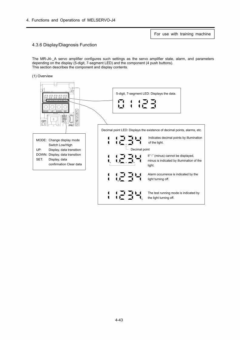
4. Functions and Operations of MELSERVO-J4
4-43
4.3.6 Display/Diagnosis Function The MR-J4-_A servo amplifier configures such settings as the servo amplifier state, alarm, and parameters depending on the display (5-digit, 7-segment LED) and the component (4 push buttons). This section describes the component and display contents. (1) Overview
MODE UP DOWN SET
MODE: Change display mode
Switch Low/High
UP: Display, data transition
DOWN: Display, data transition
SET: Display, data
confirmation Clear data
5-digit, 7-segment LED: Displays the data.
Decimal point LED: Displays the existence of decimal points, alarms, etc.
Decimal point
Indicates decimal points by illumination
of the light.
If “-” (minus) cannot be displayed,
minus is indicated by illumination of the
light.
Alarm occurrence is indicated by the
light turning off.
The test running mode is indicated by
the light turning off.
For use with training machine

4. Functions and Operations of MELSERVO-J4
4-44
(2) Display Flow
The following display mode is displayed if the "MODE" button is pressed once. For the individual display mode contents, refer to the details on the following pages. Enable basic setting parameter [Pr.PA19 Parameter write inhibited] to refer to and operate the gain/filter parameters, the extension setting parameters, and the I/O setting parameters.
FunctionTransition of display mode Initial screen
Status display
One-touch tuning.Select for one-touch tuning.
Current alarm display, alarmhistory display, and parametererror No. display.
Display and setting of basicsetting parameters.
Display and setting of gain/filterparameters.
Display and setting of extensionsetting parameters.
Display and setting ofinput/output setting parameters.
Display and setting of extensionsetting parameter 2.
Display and setting of extensionsetting 3 parameters.
Sequence display, external signaldisplay, output signal (DO) forcedoutput, test operation, software versiondisplay, VC auto offset, servo motorseries ID display, servo motor type IDdisplay, servo motor encoder ID display,drive recorder enable/disable display.
Displays at power-on.(Note)
One-touch tuning
Diagnostics
Alarm
Basic settingparameters
Gain/filterparameters
Extension settingparameters
I/O settingparameters
Extension setting2 parameters
Extension setting2 parameters
button
Servo status display.
Note: When the axis name is set to the servo amplifier by MR Configurator2, the axisname is displayed first before the servo status is displayed.
For use with training machine

4. Functions and Operations of MELSERVO-J4
4-45
(3) Status Display
The servo status during operation can be displayed on the 5-digit, 7-segment LED indicator. The contents can be changed arbitrarily with the "UP" or "DOWN" button. When selected, a symbol is displayed and the data is displayed by pressing the "SET" button. However, the data is displayed only at power-on after the status display symbol selected in [Pr. PC36] is displayed for 2 s.
(a) Display transition
Shift to the status display mode using the "MODE" button, and transition the display as follows by pressing the "UP" or "DOWN" button.
DOWN
UP
Module total power consumption 2 (100 kw units)
Servo motor speed
Cumulative feedbackpulses
Pulse droop
Cumulative commandpulses
Command pulsefrequency
Analog speedcommand voltageAnalog speed limitvoltage
Analog torque limitvoltageAnalog torquecommand voltage
Regenerative loadratio
Effective load ratio
Peak load ratio
Instantaneous torque
Within one-revolutionposition (1-pulseunits)
Within one-revolution position(1000-pulse units)
ABS counter
Load to motor inertia ratio
Bus voltage
Encoder inside temperature
Settling time
Oscillation detectionfrequency
Number of tough driveoperations
Module power consumption 1(1 W units)
Module power consumption 2(1 kW units)
Module total powerconsumption 1 (1 Wh units)
Module total power consumption2 (100 kWh units)
To cumulative feedback pulses
For use with training machine
Droop pulse

4. Functions and Operations of MELSERVO-J4
4-46
(b) Display example
A display example is shown in the following table.
11252 rev
ABS counter
-12566 revON
Item StatusDisplay method
Servo amplifier display
Forward rotation at
2500 r/min
Servo motor speed
Reverse rotation at
3000 r/min
Load to motor inertia
ratio
During reverse operation, "-" is displayed.
x 7.00
At negative power, the 2, 3, 4, and 5 digit
dots illuminate.
For use with training machine

4. Functions and Operations of MELSERVO-J4
4-47
(4) Status display list
The servo statuses that can be displayed are shown in the following table.
Table 4.4 (1/2)
Status display Sym-bol
Unit Description
Cumulative feedback pulses
C pulse
Counts and display the return pulse from the servo motor encoder. Although the count continues even after ±99999 is exceeded, only 5 digits are displayed on the servo amplifier display. Therefore, the last 5 digits of the actual value are displayed. Press the "SET" button to set to 0. With a minus numerical value, the 2nd, 3rd, 4th, and 5th decimal points are illuminated.
Servo motor speed r r/min Displays the servo motor speed. 0.1 r/min units are rounded off and displayed.
Droop pulse E pulse
Displays the droop pulse of the deviation counter. With a reverse rotation pulse, the 2nd, 3rd, 4th, and 5th decimal points are illuminated. Although the count continues even after ±99999 is exceeded, only 5 digits are displayed on the servo amplifier display. Therefore, the last 5 digits of the actual value are displayed. The displayed pulse count is in encoder pulse units.
Cumulative command pulses
P pulse
Counts and display position command input pulse. Because the value displayed is from before electronic gear (CMX/CDV) multiplication, the display of the cumulative feedback pulses may not match. Although the count continues even after ±99999 is exceeded, only 5 digits are displayed on the servo amplifier display. Therefore, the last 5 digits of the actual value are displayed. Press the "SET" button to set to 0. At reverse rotation, the 2nd, 3rd, 4th, and 5th decimal points are illuminated.
Command pulse frequency
n kpps The frequency of the position command input pulse is displayed. The value before electronic gear (CMX/CDV) multiplication is displayed.
Analog speed command voltage Analog speed limit voltage
F V
(1) Torque control mode The input voltage of the analog speed limit (VLA) is displayed.
(2) Speed control mode The input voltage of the analog speed command (VC) is displayed.
Analog torque command voltage Analog torque limit voltage
U V
(1) Position control mode/speed control mode The voltage of the analog torque limit (TLA) is displayed. (2) Torque control mode The voltage of the analog torque command (TC) is displayed.
Regenerative load ratio
L % The regenerative power ratio with respect to the permissible regenerative power is displayed as %.
Effective load ratio J % The continuous effective load torque is displayed. The rated torque is assumed to be 100%, and the effective value of the previous 15 seconds is displayed.
Peak load ratio b % The maximum value of the generated torque is displayed. The rated torque is assumed to be 100%, and the maximum value of the previous 15 seconds is displayed.
Instantaneous torque T % The instantaneous torque is displayed. The generated torque value, assuming the rated torque as 100%, is displayed in real time.
Within one-revolution position (1 pulse unit)
Cy1 pulse
Within one-revolution position is displayed in increments of encoder pulses. Although the count continues even after ±99999 is exceeded, only 5 digits are displayed on the servo amplifier display. Therefore, the last 5 digits of the actual value are displayed. Rotating in the CCW direction causes addition.
Within one-revolution position (100 pulse unit)
Cy2 1000 pulse
Within one-revolution position is displayed in increments of 1000 encoder pulses. Rotating in the CCW direction causes addition.
ABS counter LS rev In absolute position detection systems, the travel distance from the home position is displayed in the multi-revolution counter value of the absolute position encoder.
Load to motor inertia ratio
dC times The estimated ratio of load moment of inertia converted into an equivalent value on the servo motor shaft with respect to the servo motor moment of inertia is displayed.
Bus voltage Pn V The voltage of the main circuit converter (between P-N) is displayed. Encoder inside temperature
ETh °C The internal temperature detected by encoder is displayed.
Settling time ST ms The settling time is displayed. When 1000 mm/s is exceeded, "1000" is displayed. Oscillation detection frequency
oF Hz The frequency at the time of oscillation detection is displayed.
Number of tough drive operations
Td times The number of times that the tough drive function has been operated is displayed.
Module power consumption 1 (1 W unit)
PC1 W
Module power consumption is displayed in 1 W units. The power drive is displayed when positive, and regenerative driving is displayed when negative. Although the count continues even after ±99999 is exceeded, only 5 digits are displayed on the servo amplifier display. Therefore, the last 5 digits of the actual value are displayed.
For use with training machine

4. Functions and Operations of MELSERVO-J4
4-48
Table 4.4 (2/2)
Status display Sym- bol
Unit Description
Module power consumption 2 (1 kW unit)
PC2 kW Module power consumption is displayed in 1 kW units. The power drive is displayed when positive, and regenerative driving is displayed when negative.
Module total power consumption 1 (1 Wh unit)
TPC1 Wh
Module total power consumption is displayed in 1 Wh units. The positive value at the time of power driving is integrated, and a negative value at the time of regenerative driving is integrated. Although the count continues even after ±99999 is exceeded, only 5 digits are displayed on the servo amplifier display. Therefore, the last 5 digits of the actual value are displayed.
Module total power consumption 2 (100 kWh unit)
TPC2 100 kWh
Module total power consumption is displayed in 100 kWh units. The positive value at the time of power driving is integrated, and a negative value at the time of regenerative driving is integrated.
(5) Change of status display screen The status display items of the servo amplifier display at power-on can be changed by changing [Pr. PC36]. The display items in the initial status can be changed as follows in the control mode.
Control mode Displayed items
Position Cumulative feedback pulses Position/speed Cumulative feedback pulses/servo motor speed
Speed Servo motor speed Speed/torque Servo motor speed/analog torque command voltage
Torque Analog torque command voltage
Torque/position Analog torque command voltage/cumulative feedback
pulses
For use with training machine

4. Functions and Operations of MELSERVO-J4
4-49
(6) Diagnostic display mode
This mode is used to check the status of the external sequence.
Table 4.5 Diagnostic display list table
Name Display Description
Sequence
Not ready. When initializing or when an alarm occurs.
Ready. When initialization is complete and operation is possible by servo-on.
Drive recorder enabled/disabled display
Drive recorder enabled. When an alarm occurs this state, the status when the alarm occurred is recorded by the drive recorder.
Drive recorder disabled. In the following statuses, the drive recorder will not operate. 1. When the MR Configurator2 graph function is in use.2. When the machine analyzer function is in use. 3. When [Pr. PF21] is set to "-1".
External I/O signals display Refer to section 4.3.9.
The ON/OFF statuses of external I/O signals are displayed. For each segment, the upper portion corresponds to the input signal and the lower portion corresponds to the output signal.
Output signal (DO) forced output
The digital output signal can be forced ON/OFF.
Test operation mode
JOG operation
JOG operation can be executed when there is no command from an external controller. For details, refer to section 4.3.13 (2).
Positioning operation
Positioning operation can be executed once when there is no command from an external controller. MR Configurator2 (setup software) SW1DNC-MRC2-J is required to perform positioning operation.
Motor-less operation
The status display can be monitored without connecting the servo motor when the output signal is output according to the external input signal as if the servo motor were actually operating. For details, refer to section 4.3.13 (4).
Machine analyzer operation
The resonance point of the machine system can be measured only by connecting the servo amplifier. MR Configurator2 (setup software) SW1DNC-MRC2-J is required to perform machine analyzer operation.
For manufacturer adjustment
This is used for manufacturer adjustment.
For use with training machine

4. Functions and Operations of MELSERVO-J4
4-50
Name Display Description
Software version low
Displays the software version.
Software version high
Displays the software system number.
VC automatic offset
Even if VC (analog speed command) and VLA (analog speed limit) are set to 0 V, when the servo motor rotates slowly by the offset voltage of the internal and external analog circuits of the servo amplifier, the offset voltage is automatically zero-adjusted. To use, enable according to the following procedure. When enabled, the offset voltage where the value of [Pr.PC37] is auto-adjusted is enforced. (1) Press "SET" once. (2) Set 1 as the 1st digit in "UP" and "DOWN". (3) Press "SET". If the VC or VLA input voltage is between -0.4 and +0.4 V, this function cannot be used.
Motor series ID
When the "SET" button is pressed, the motor series ID of the currently connected servo motor is displayed. For a display description, refer to the MELSERVO Servo Motor Instruction Manual (Set 3).
Motor type ID
When the "SET" button is pressed, the motor type ID of the currently connected servo motor is displayed. For a display description, refer to the MELSERVO Servo Motor Instruction Manual (Set 3).
Detector ID
When the "SET" button is pressed, the detector ID of the currently connected servo motor is displayed. For a display description, refer to the MELSERVO Servo Motor Instruction Manual (Set 3).
For manufacturer adjustment
This is used for manufacturer adjustment.
For manufacturer adjustment
This is used for manufacturer adjustment.
For use with training machine

4. Functions and Operations of MELSERVO-J4
4-51
(7) Alarm display mode
The current alarm and previous alarm history and the parameter errors are displayed. The generated alarm number and the parameter number with an error are displayed in the lower two digits of the display. A display example is shown in the following table.
Table 4.6
Name Display Description
Current alarm
No alarm has occurred.
[AL. 33.1 Main circuit voltage malfunction] occurred. Flashes when an alarm occurs.
Alarm history
[AL.50.1 Overload thermal error at the time of operation] was not generated the previous time.
[AL.33.1 Main circuit voltage malfunction] was not generated for the last 2 times.
[AL.10.1 Voltage drop in the control circuit power] was not generated for the last 3 times.
...
...
The alarm has not gone off for the last 10 times. The alarm has not gone off for the last 11 times. The alarm has not gone off for the last 12 times.
...
...
The alarm has not gone off for the last 16 times.
Parameter error number
[AL. 37 Parameter error] has not occurred.
A fault exists in the data contents of [Pr. PA12 Reverse rotation torque limit].
For use with training machine

4. Functions and Operations of MELSERVO-J4
4-52
Function when an alarm occurs (1) The currently generated alarm is displayed on any mode screen. (2) The other screens can be viewed by pressing the component button even when an alarm has occurred. At
this time, the decimal point at the 4th digit keeps flashing. (3) Clear the alarm by any of the following methods after removing the cause.
(a) Turn the power supply off and on. (b) Press the "SET" button on the current alarm screen. (c) Turn RES (reset) on.
(4) Erase the alarm history with [Pr. PC18]. (5) Shift to the next history using "UP" or "DOWN".
For use with training machine

4. Functions and Operations of MELSERVO-J4
4-53
(8) Display operation
Display and parameter settings are configured by the LED indicator and the push button switch (following figure) on the front of the amplifier. The following section explains the operating procedure.
MODE UP DOWN SET
MODE: Change display mode
Switch Low/High
UP: Display, data transition
DOWN: Display, data transition
SET: Display, data confirmation
Clear data
(8-1) Power-on (1) Turn the servo-on signal (SON) OFF. (2) When the power supply (NFB) is turned on, C
(cumulative feedback pulses) is displayed on the display. (In position control mode)
Notice: The initial display at power-on changes according to the control mode. In position control mode: C (cumulative feedback pulses) In speed control mode: r (motor rotation speed) In torque control mode: U (torque command voltage) In addition, the initial display at power-on can be changed by parameter number PC36.
(8-2) SON signal ON
When the Servo-on signal (SON) is ON, operation is possible and the servo motor shaft is locked. (Servo-lock state) If there is no servo-lock, a servo-on state has not been initiated. Check for an external sequence in the diagnostics display. Check method
Power-on
Press MOD 2 times.
Note: One-touch tuning is initiated first.
Turn ON SON. This display appears with servo-on.
For use with training machine

4. Functions and Operations of MELSERVO-J4
4-54
(8-3) Status display
The initial display of the status display differs depending on the control mode. In position control mode, when <DOWN> is pressed under 'Cumulative feedback pulses' in the initially displayed status, the display contents of the figure in section 4.3.6 (2) shift from top to bottom. Press the <UP> switch to return the display to the top. When the initial display is to be changed to arbitrary contents, selection can be done with parameter number PC18.
(8-4) Diagnostics display
The display shifts to the diagnostics display mode when the <MODE> button is pressed from the status display mode. The contents to be viewed can be accessed with the <UP> and <DOWN> buttons.
(8-5) Alarm display
To view the alarm contents or the history, the current alarm code is displayed by pressing the <MODE> button again from the diagnostics display mode. When no current alarm is generated,
is displayed. By pressing the <UP> button, the previous alarm code is displayed and the history up to 16 previous alarms can be viewed. Alarm history is stored even after power-off.
Current alarm|
(Error excessive) * The display flashes.
<UP> |
Previous alarm |
(Overvoltage) <UP>
|
Second previous alarm
(No alarm generated)
(8-6) When an alarm occurs during operation
When operating an alarm during motor operation, the current alarm can be immediately displayed from any display screen.
Alarm generation
(Overspeed) Note: The other screens can be viewed by pressing
the component button even when an alarm has occurred. At this time, the decimal point at the 4th digit keeps flashing. Example: When the effective load ratio is being viewed during alarm generation The decimal point at the 4th digit flashes.
For use with training machine

4. Functions and Operations of MELSERVO-J4
4-55
4.3.7 Parameters In digital servos, operations such as gain adjustment and offset adjustment of analog I/O signals, which is performed by conventional analog servos, are set by parameters. Moreover, if a mode other than the position/speed/torque control mode is selected, the functions are switched. A parameter list for MR-J4-type servo amplifiers is shown in the following table.
CAUTION
Never perform extreme adjustments and changes to the parameters,
or the operation may become unstable. If fixed values are written in the digits of a parameter, do not change
these values. Do not change parameters for manufacturer settings.
(1) Parameter list (For details on the operation method, refer to section 4.3.8.) When using this servo as the position control mode, basic parameters at the time of installation can be set mainly by setting basic setting parameters. To enable a parameter whose abbreviation is preceded by *, turn the power OFF and then ON after setting the parameter.
(a) Basic setting parameters ([Pr. PA_ _ ])
No. Abbre-viation
Name Initial value Unit Control mode
Posi-tion
Speed Torque
PA01 *STY Operation mode 1000h PA02 *REG Regenerative option 0000h PA03 *ABS Absolute position detection system 0000h PA04 *AOP1 Function selection A-1 2000h PA05 *FBP Number of command input pulses per revolution 10000
PA06 CMX Electronic gear numerator (command input pulse magnification numerator)
1
PA07 CDV Electronic gear denominator (command input pulse magnification denominator)
1
PA08 ATU Auto tuning mode 0001h PA09 RSP Auto tuning response 16 PA10 INP In-position range 100 pulse PA11 TLP Forward rotation torque limit 100.0 % PA12 TLN Reverse rotation torque limit 100.0 % PA13 *PLSS Command pulse input form 0100h PA14 *POL Rotation direction selection 0
PA15 *ENR Encoder output pulses 4000 pulse/
rev
PA16 *ENR2 Encoder output pulses 2 1 PA17
For manufacturer setting 0000h
PA18 0000h PA19 *BLK Parameter writing inhibit 00AAh PA20 *TDS Tough drive setting 0000h PA21 *AOP3 Function Selection A-3 0001h PA22 For manufacturer setting 0000h PA23 DRAT Drive recorder arbitrary alarm trigger setting 0000h PA24 AOP4 Function Selection A-4 0000h
PA25 OTHO
V One-touch tuning - Overshoot permissible level 0 [%]
PA26
For manufacturer setting
0000h PA27 0000h PA28 0000h PA29 0000h PA30 0000h PA31 0000h PA32 0000h

4. Functions and Operations of MELSERVO-J4
4-56
(b) Gain/filter setting parameter ([Pr. PB_ _ ])
No. Abbre-viation
Name Initial value Unit Control mode
Posi-tion
Speed Torque
PB01 FILT Adaptive tuning mode (adaptive filter II) 0000h
PB02 VRFT Vibration suppression control tuning mode (advanced vibration suppression control II)
0000h
PB03 PST Position command acceleration/deceleration time constant (position smoothing)
0 ms
PB04 FFC Feed forward gain 0 % PB05 For manufacturer setting 500 PB06 GD2 Load to motor inertia ratio 7.00 times PB07 PG1 Model loop gain 15.0 rad/s PB08 PG2 Position loop gain 37.0 rad/s PB09 VG2 Speed loop gain 823 rad/s PB10 VIC Speed integral compensation 33.7 ms PB11 VDC Speed differential compensation 980 PB12 OVA Overshoot amount compensation 0 [%] PB13 NH1 Machine resonance suppression filter 1 4500 Hz PB14 NHQ1 Notch shape selection 1 0000h PB15 NH2 Machine resonance suppression filter 2 4500 Hz PB16 NHQ2 Notch shape selection 2 0000h PB17 NHF Shaft resonance suppression filter 0000h PB18 LPF Low-pass filter setting 3141 rad/s PB19 VRF11 Vibration suppression control 1 - Vibration frequency 100.0 Hz PB20 VRF12 Vibration suppression control 1 - Resonance frequency 100.0 Hz PB21 VRF13 Vibration suppression control 1 - Vibration frequency damping 0.00 PB22 VRF14 Vibration suppression control 1 - Resonance frequency damping 0.00 PB23 VFBF Low-pass filter selection 0000h PB24 *MVS Slight vibration suppression control selection 0000h PB25 *BOP1 Function selection B-1 0000h PB26 CDP Gain switching selection 0000h
PB27 CDL Gain switching condition 10 [kpps], [pulse], [r/min]
PB28 CDT Gain switching time constant 1 ms PB29 GD2B Load to motor inertia ratio after gain switching 7.00 times PB30 PG2B Position loop gain after gain switching 0.0 rad/s PB31 VG2B Speed loop gain after gain switching 0 rad/s PB32 VICB Speed integral compensation after gain switching 0.0 ms
PB33 VRF1B Vibration suppression control 1 - Vibration frequency after gain switching
0.0 Hz
PB34 VRF2B Vibration suppression control 1 - Resonance frequency after gain switching
0.0 Hz
PB35 VRF3B Vibration suppression control 1 - Vibration frequency damping after gain switching
0.00
PB36 VRF4B Vibration suppression control 1 - Resonance frequency damping after gain switching
0.00
PB37
For manufacturer setting
1600 PB38 0.00 PB39 0.00 PB40 0.00 PB41 0000h PB42 0000h PB43 0000h PB44 0.00 PB45 CNHF Command notch filter 0000h PB46 NH3 Machine resonance suppression filter 3 4500 Hz PB47 NHQ3 Notch shape selection 3 0000h PB48 NH4 Machine resonance suppression filter 4 4500 Hz PB49 NHQ4 Notch shape selection 4 0000h PB50 NH5 Machine resonance suppression filter 5 4500 Hz

4. Functions and Operations of MELSERVO-J4
4-57
No. Abbre-viation
Name Initial value Unit Control mode
Posi-tion
Speed Torque
PB51 NHQ5 Notch shape selection 5 0000h PB52 VRF21 Vibration suppression control 2 - Vibration frequency 100.0 Hz PB53 VRF22 Vibration suppression control 2 - Resonance frequency 100.0 Hz PB54 VRF23 Vibration suppression control 2 - Vibration frequency damping 0.00 PB55 VRF24 Vibration suppression control 2 - Resonance frequency damping 0.00
PB56 VRF21
B Vibration suppression control 2 - Vibration frequency after gain switching
0.0 Hz
PB57 VRF22
B Vibration suppression control 2 - Resonance frequency after gain switching
0.0 Hz
PB58 VRF23
B Vibration suppression control 2 - Vibration frequency damping after gain switching
0.00
PB59 VRF24
B Vibration suppression control 2 - Resonance frequency damping after gain switching
0.00
PB60 PG1B Model loop gain after gain switching 0.0 rad/s PB61
For manufacturer setting
0.0 PB62 0000h PB63 0000h PB64 0000h
(c) Extension setting parameters ([Pr. PC_ _ ])
No. Abbre-viation
Name Initial value Unit Control mode
Posi-tion
Speed Torque
PC01 STA Acceleration time constant 0 ms PC02 STB Deceleration time constant 0 ms PC03 STC S-curve acceleration/deceleration time constant 0 ms PC04 TQC Torque command time constant 0 ms PC05 SC1 Internal speed command 1 100 r/min
Internal speed limit 1 PC06 SC2 Internal speed command 2 500 r/min
Internal speed limit 2 PC07 SC3 Internal speed command 3 1000 r/min
Internal speed limit 3 PC08 SC4 Internal speed command 4 200 r/min
Internal speed limit 4 PC09 SC5 Internal speed command 5 300 r/min
Internal speed limit 5 PC10 SC6 Internal speed command 6 500 r/min
Internal speed limit 6 PC11 SC7 Internal speed command 7 800 r/min
Internal speed limit 7 PC12 VCM Analog speed command maximum speed 0 r/min
Analog speed limit maximum speed PC13 TLC Analog torque command maximum output 100.0 % PC14 MOD1 Analog monitor 1 output 0000h PC15 MOD2 Analog monitor 2 output 0001h PC16 MBR Electromagnetic brake sequence output 0 ms PC17 ZSP Zero speed 50 r/min PC18 *BPS Alarm history clear 0000h PC19 *ENRS Encoder output pulses selection 0000h
PC20 *SNO Station number setting 0 Statio
n
PC21 *SOP RS-422 communication function selection 0000h PC22 *COP1 Function selection C-1 0000h PC23 *COP2 Function selection C-2 0000h PC24 *COP3 Function selection C-3 0000h PC25 For manufacturer setting 0000h PC26 *COP5 Function selection C-5 0000h PC27 *COP6 Function selection C-6 0000h PC28
For manufacturer setting 0000h
PC29 0000h

4. Functions and Operations of MELSERVO-J4
4-58
No. Abbre-viation
Name Initial value Unit Control mode
Posi-tion
Speed Torque
PC30 STA2 Acceleration time constant 2 0 ms PC31 STB2 Deceleration time constant 2 0 ms PC32 CMX2 Command input pulse multiplication numerator 2 1 PC33 CMX3 Command input pulse multiplication numerator 3 1 PC34 CMX4 Command input pulse multiplication numerator 4 1 PC35 TL2 Internal torque limit 2 100.0 % PC36 *DMD Status display selection 0000h PC37 VCO Analog speed command offset 0 mV
Analog speed limit offset PC38 TPO Analog torque command offset 0 mV
Analog torque limit offset PC39 MO1 Analog monitor 1 offset 0 mV PC40 MO2 Analog monitor 2 offset 0 mV PC41
For manufacturer setting 0
PC42 0 PC43 ERZ Error excessive alarm detection level 0 rev PC44
For manufacturer setting
0000h PC45 0000h PC46 0 PC47 0 PC48 0 PC49 0 PC50 0000h PC51 RSBR Forced stop deceleration time constant 100 ms PC52
For manufacturer setting 0
PC53 0
PC54 RSUP1 Vertical axis freefall prevention compensation amount 0 0.0001 rev
PC55
For manufacturer setting
0 PC56 100 PC57 0000h PC58 0 PC59 0000h PC60 *COPD Function selection C-D 0000h PC61
For manufacturer setting
0000h PC62 0000h PC63 0000h PC64 0000h PC65 0000h PC66 0000h PC67 0000h PC68 0000h PC69 0000h PC70 0000h PC71
2 0000h
PC72 0000h PC73 0000h PC74 0000h PC75 0000h PC76 0000h PC77 0000h PC78 0000h PC79 0000h PC80 0000h

4. Functions and Operations of MELSERVO-J4
4-59
(d) I/O setting parameters ([Pr. PD_ _ ])
No. Abbre-viation
Name Initial value Unit Control mode
Posi-tion
Speed Torque
PD01 *DIA1 Input signal automatic on selection 1 0000h PD02 For manufacturer setting 0000h PD03 *DI1L Input device selection 1L 0202h PD04 *DI1H Input device selection 1H 0002h PD05 *DI2L Input device selection 2L 2100h PD06 *DI2H Input device selection 2H 0021h PD07 *DI3L Input device selection 3L 0704h PD08 *DI3H Input device selection 3H 0007h PD09 *DI4L Input device selection 4L 0805h PD10 *DI4H Input device selection 4H 0008h PD11 *D15L Input device selection 5L 0303h PD12 *DI5H Input device selection 5H 0003h PD13 *DI6L Input device selection 6L 2006h PD14 *DI6H Input device selection 6H 0020h PD15 For manufacturer setting 0000h
PD16 0000h PD17 *DI8L Input device selection 8L 0A0Ah PD18 *DI8H Input device selection 8H 0000h PD19 *DI9L Input device selection 9L 0B0Bh PD20 *DI9H Input device selection 9H 0000h PD21 *DI10L Input device selection 10L 2323h PD22 *DI10H Input device selection 10H 0023h PD23 *DO1 Output device selection 1 0004h PD24 *DO2 Output device selection 2 000Ch PD25 *DO3 Output device selection 3 0004h PD26 *DO4 Output device selection 4 0007h PD27 For manufacturer setting 0003h PD28 *DO6 Output device selection 6 0002h PD29 *DIF Input filter setting 0004h PD30 *DOP1 Function selection D-1 0000h PD31 For manufacturer setting 0000h PD32 *DOP3 Function selection D-3 0000h PD33 For manufacturer setting 0000h PD34 DOP5 Function selection D-5 0000h PD35 For manufacturer setting 0000h PD36 0000h PD37 0000h PD38 0 PD39 0 PD40 0 PD41 0000h PD42 0000h PD43 0000h PD44 0000h PD45 0000h PD46 0000h PD47 0000h PD48 0000h
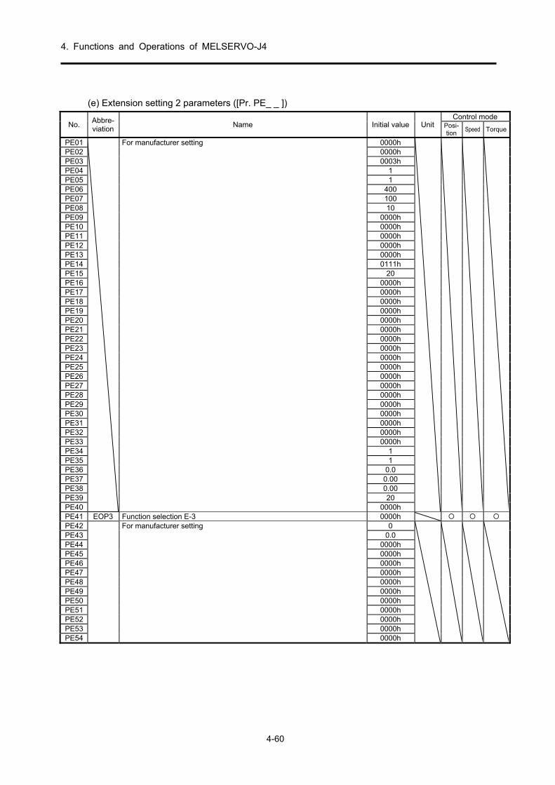
4. Functions and Operations of MELSERVO-J4
4-60
(e) Extension setting 2 parameters ([Pr. PE_ _ ])
No. Abbre-viation
Name Initial value Unit Control mode
Posi-tion
Speed Torque
PE01 For manufacturer setting 0000h
PE02 0000h PE03 0003h PE04 1 PE05 1 PE06 400 PE07 100 PE08 10 PE09 0000h PE10 0000h PE11 0000h PE12 0000h PE13 0000h PE14 0111h PE15 20 PE16 0000h PE17 0000h PE18 0000h PE19 0000h PE20 0000h PE21 0000h PE22 0000h PE23 0000h PE24 0000h PE25 0000h PE26 0000h PE27 0000h PE28 0000h PE29 0000h PE30 0000h PE31 0000h PE32 0000h PE33 0000h PE34 1 PE35 1 PE36 0.0 PE37 0.00 PE38 0.00 PE39 20 PE40 0000h PE41 EOP3 Function selection E-3 0000h PE42 For manufacturer setting 0
PE43 0.0 PE44 0000h PE45 0000h PE46 0000h PE47 0000h PE48 0000h PE49 0000h PE50 0000h PE51 0000h PE52 0000h PE53 0000h PE54 0000h

4. Functions and Operations of MELSERVO-J4
4-61
No. Abbre-viation
Name Initial value Unit Control mode
Posi-tion
Speed Torque
PE55 For manufacturer setting 0000h
PE56 0000h PE57 0000h PE58 0000h PE59 0000h PE60 0000h PE61 0.00 PE62 0.00 PE63 0.00 PE64 0.00
(f) Extension setting 3 parameters ([Pr. PF_ _ ])
No. Abbre-viation
Name Initial value Unit Control mode
Posi-tion
Speed Torque
PF01 For manufacturer setting 0000h
PF02 0000h PF03 0000h PF04 0 PF05 0 PF06 0000h PF07 1 PF08 1 PF09 *FOP5 Function selection F-5 0000h PF10 For manufacturer setting 0000h
PF11 0000h PF12 10000 PF13 100 PF14 100 PF15 DBT Electronic dynamic brake operating time 2000 [ms] PF16 For manufacturer setting 0000h
PF17 10 PF18 0000h PF19 0000h PF20 0000h PF21 DRT Drive recorder switching time setting 0 [s] PF22 For manufacturer setting 200 PF23 OSCL1 Vibration tough drive - Oscillation detection level 50 [%] PF24 *OSCL
2 Vibration tough drive function selection 0000h
PF25 CVAT Instantaneous power failure tough drive - Detection time 200 [ms] PF26 For manufacturer setting 0
PF27 0 PF28 0 PF29 0000h PF30 0 PF31 FRIC Machine diagnosis function - Friction judgment speed 0 [r/min]
PF32 For manufacturer setting 50
PF33 0000h PF34 0000h PF35 0000h PF36 0000h PF37 0000h PF38 0000h PF39 0000h PF40 0000h

4. Functions and Operations of MELSERVO-J4
4-62
No. Abbre-viation
Name Initial value Unit Control mode
Posi-tion
Speed Torque
PF41 For manufacturer setting 0000h
PF42 0000h PF43 0000h PF44 0000h PF45 0000h PF46 0000h PF47 0000h PF48 0000h
(2) Parameters that must be set or confirmed before operation
When there is a mistake when setting the parameters explained here, the motor will not work and an alarm will occur. Make sure to check before operation, and if different from the initial value, change the settings.
(a) Parameter writing inhibit
Parameter Initial value Unit
Setting range
Control mode
No. Abbre-viation
Name Posi-tion
Speed Torque
PA19 *BLK Parameter writing inhibit 00AAh Refer to the
text
POINT
After setting this parameter, it can be enabled by turning the power supply
OFF→ON.
With this servo amplifier, the basic setting parameters, gain/filter parameters, and extension setting parameters can be changed in the shipped state. Writing can be prohibited in order to prevent improper changes by setting parameter number PA19. The following table shows the references and parameters for which writing is enabled by setting parameter number PA19. Operation of parameters marked with is possible.
PA19 Setting value
operationPA PB PC PD PE PF
Other than the below
Read Write
000Ah Read Only 19 Write Only 19
000Bh Read Write
000Ch Read Write
00AAh (Initial value)
Read Write
100Bh Read Write Only 19
100Ch Read Write Only 19
10AAh Read Write Only 19
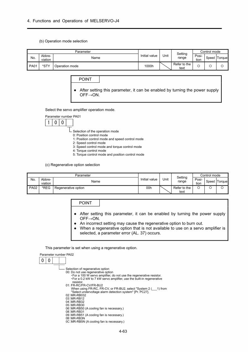
4. Functions and Operations of MELSERVO-J4
4-63
(b) Operation mode selection
Parameter Initial value Unit
Setting range
Control mode
No. Abbre-viation
Name Posi- tion
Speed Torque
PA01 *STY Operation mode 1000h Refer to the
text
POINT
After setting this parameter, it can be enabled by turning the power supply
OFF→ON.
Select the servo amplifier operation mode.
1 00
Parameter number PA01
Selection of the operation mode0: Position control mode1: Position control mode and speed control mode2: Speed control mode3: Speed control mode and torque control mode4: Torque control mode5: Torque control mode and position control mode
(c) Regenerative option selection
Parameter Initial value Unit
Setting range
Control mode No. Abbre-
viation Name
Posi- tion
Speed Torque
PA02 *REG Regenerative option 00h Refer to the text
POINT
After setting this parameter, it can be enabled by turning the power supply
OFF→ON. An incorrect setting may cause the regenerative option to burn out. When a regenerative option that is not available to use on a servo amplifier is
selected, a parameter error (AL. 37) occurs.
This parameter is set when using a regenerative option.
0 0
Parameter number PA02
Selection of regenerative option00: Do not use regenerative option・For a 100 W servo amplifier, do not use the regenerative resistor.・For a 0.2 kW to 7 kW servo amplifier, use the built-in regenerative
resistor.01: FR-RC/FR-CV/FR-BU2
When using FR-RC, FR-CV, or FR-BU2, select "System 2 (___1) from"Select undervoltage alarm detection system" [Pr. PC27].
02:MR-RB03203:MR-RB1204:MR-RB3205:MR-RB3006:MR-RB50 (A cooling fan is necessary.)08:MR-RB3109:MR-RB51 (A cooling fan is necessary.)0B:MR-RB3N0C:MR-RB5N (A cooling fan is necessary.)

4. Functions and Operations of MELSERVO-J4
4-64
(d) Use absolute position detection system
Parameter Initial value Unit
Setting range
Control mode
No. Abbre- viation
Name Posi- tion
Speed Torque
PA03 *ABS Absolute position detection system 0h Refer to the text
POINT
After setting this parameter, it can be enabled by turning the power supply OFF→ON.
This parameter is set when using the absolute position detection system in the position control mode.
0 0 0
Parameter number PA03
Select "Absolute position detection system".0: Disabled (incremental system)1: Enabled: (Absolute position detection
system by DIO)
(e) Use electromagnetic brake interlock (MBR)
Parameter Initial value Unit
Setting range
Control mode
No. Abbre- viation
Name Posi- tion
Speed Torque
PA04 *AOP1 Function selection A-1 2000h Refer to the text
POINT
After setting this parameter, it can be enabled by turning the power supply OFF→ON.
This parameter is set when assigning the electromagnetic brake.
00 0
Parameter number PA04
Select "Forced stop deceleration function".0: Forced stop deceleration function is
disabled (use EM1)2: Forced stop deceleration function is
enabled (use EM2)Refer to the following table for details.
Setting value EM2/EM1 Deceleration method
EM2 or EM1 is off Alarm occurred
0 _ _ _ EM1 MBR (electromagnetic brake interlock) turns off without the forced stop deceleration.
MBR (electromagnetic brake interlock) turns off without the forced stop deceleration.
2 _ _ _ EM2 MBR (electromagnetic brake interlock) turns off after the forced stop deceleration.
MBR (electromagnetic brake interlock) turns off after the forced stop deceleration.
(f) Number of command input pulses per servo motor revolution
Parameter Initial value Unit Setting range
Control mode
No. Abbre- viation
Name Posi- tion
Speed Torque
PA05 *FBP Number of command input pulses per revolution
10000 1000 to 1000000
POINT
After setting this parameter, it can be enabled by turning the power supply OFF→ON.
The servo motor rotates once with the set command input pulse. When "Number of command input pulses per revolution (1 _ _ _ )" is selected in "Electronic gear selection" of [Pr. PA21], the set value of this parameter is enabled.

4. Functions and Operations of MELSERVO-J4
4-65
(g) Electronic gear
Parameter Initial value Unit
Setting range
Control mode
No. Abbre- viation
Name Posi- tion
Speed Torque
PA06 CMX Electronic gear numerator (command pulse multiplication numerator)
1 1 to
16777215
PA07 CDV Electronic gear denominator (command pulse multiplication denominator)
1 1 to
16777215
CAUTION
When there are setting errors, unexpected high-speed rotations may occur, leading to damage.
POINT
The standard setting range of the electronic gear is CDV
CMX<
10
1<4000. When a
value outside the range is set, there is noise during acceleration/deceleration, and operation may not be possible at the set speed and the acceleration/deceleration time constant.
The electronic gear settings must be performed in the servo-off status in order to prevent runaway due to incorrect settings.
To enable the parameter, select "Electronic gear (0 _ _ _)" or "J3A electronic gear setting value compatibility mode (2 _ _ _)" in "Electronic gear selection" for [Pr. PA21]. (1) Electronic gear concepts
The machine can also be moved at arbitrary magnification with respect to the input pulse.
CDV
FBPPt
CMX
+
-
[Pr.PA06]・[Pr.PA07]
“1000”~“1000000”
M
X16
"2"
CDVCMX"1"
[Pr.PA21](x _ _ _ )
4194304 [pulses/rev]Pt (servo motor resolution):
Number of command pulses per revolution [Pr. PA05]
Commandpulse train
Select “Electronic gear”. Electronic gear
“0” (Initial value)
Deviation counter
Servo motor
Encoder
CMX
CDV=
Parameter No.PA06
Parameter No.PA07
The calculation method of the electronic gear is explained in the following setting example.
POINT
The following parameter symbols are required when calculating the electronic gear each time. Pb: Ball screw lead [mm] n: Reduction ratio Pt: Servo motor resolution [pulse/rev] ∆0: Travel distance per command pulse [mm/pulse] ∆S: Travel distance per servo motor revolution [mm/rev] ∆θ°: Angle per pulse [°/pulse] ∆θ: Angle per revolution [°/rev]

4. Functions and Operations of MELSERVO-J4
4-66
When moving in increments of 10 μm per pulse
Machine specifications Ball screw lead: Pb=10 [mm] Reduction ratio: n=1/2 Servo motor resolution: Pt=4194304
[pulse/rev]
Pb=10[mm]NM
n=NL/NM=1/ 2NL
n
4194304 [ pulse/ rev]Servo motor
CMX
CDV=∆0/
P
ΔS
t=∆0/
P
n・Pb
t=10x10-3/
2・101
4194304
/=
1000
8388608=
125
1048576
Therefore, set CMX=1048576 and CDV=125.
Conveyor setting example When rotating in increments of 0.01° per pulse
Machine specifications Table: 360°/rev Reduction ratio: n=625/12544 Servo motor resolution: Pt=4194304
[pulse/rev]
Servo motor4194304 [pulse/rev]
Table
Timing belt: 625/12544
703125
1644167168=
360625/12544・
4194304=0.01・
Δθ
P=Δθ°・
CDV
CMX t (5.1)
In this state, because CMX is not within the setting range, a reduction of the fraction is required. If CMX is reduced until within the setting range, the first place below the decimal point is rounded off.
5625
13153337≒
5625
13153337.3=
703125
1644167168=
CDV
CMX
Therefore, set CMX=13153337 and CDV=5625.
POINT
When rotating infinitely in one direction with the index table, etc., the rounded
off errors accumulate and the index position is shifted. For instance, even if 36000 pulse is input as the command in the previous example, in the table it becomes as follows, and positioning is not possible at the same position in the table.
36000/5625
13153337/4194304
1/12544
625/360°=359.99989°

4. Functions and Operations of MELSERVO-J4
4-67
(2) Precautions when reducing
The calculated value before reduction and the calculated value after reduction must be as close as possible. With the examples in (1)(b) of this section, errors will decrease if reduced so that CDV has no fractions. If a fraction is calculated in expression (5.1) before reduction, the following applies.
83=2338.3710703125
1644167168=
CDV
CMX (5.2)
When reduced so that CMX is not a fraction, the following applies.
59=2338.58936278
14681664≒
6277.9
14681664=
703125
1644167168=
CDV
CMX (5.3)
When reduced so that CDV is not a fraction, the following applies.
22=2338.37105625
13153337≒
5625
13153337.3=
703125
1644167168=
CDV
CMX (5.4)
Therefore, it is understood that the result of expression (5.4) is a value close to the calculation result of expression (5.2). Thus, the setting values of (1)(b) in this section are CMX=13153337 and CDV=5625.
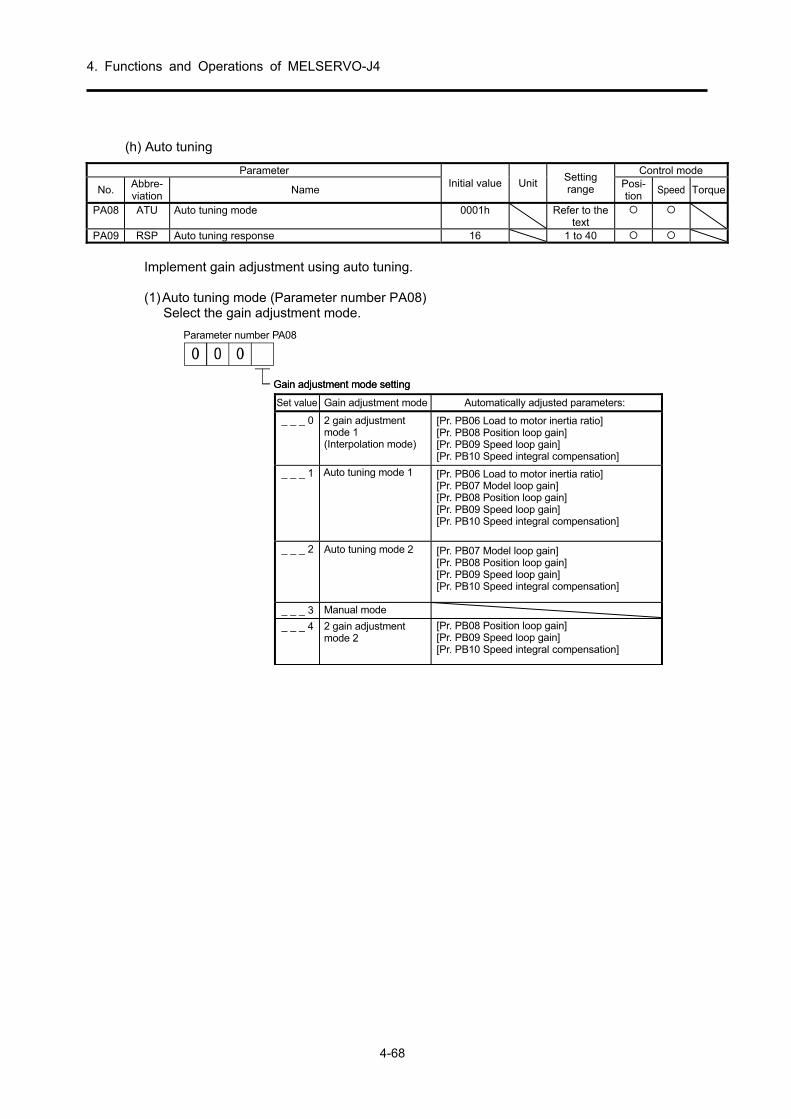
4. Functions and Operations of MELSERVO-J4
4-68
(h) Auto tuning
Parameter Initial value Unit
Setting range
Control mode
No. Abbre- viation
Name Posi- tion
Speed Torque
PA08 ATU Auto tuning mode 0001h Refer to the text
PA09 RSP Auto tuning response 16 1 to 40
Implement gain adjustment using auto tuning. (1) Auto tuning mode (Parameter number PA08)
Select the gain adjustment mode.
_ _ _ 0
_ _ _ 1 Auto tuning mode 1
_ _ _ 2
_ _ _ 3
_ _ _ 4
Parameter number PA08
Gain adjustment mode settingGain adjustment mode setting
Set value Gain adjustment mode Automatically adjusted parameters:
2 gain adjustmentmode 1(Interpolation mode)
[Pr. PB06 Load to motor inertia ratio][Pr. PB08 Position loop gain][Pr. PB09 Speed loop gain][Pr. PB10 Speed integral compensation]
[Pr. PB06 Load to motor inertia ratio][Pr. PB07 Model loop gain][Pr. PB08 Position loop gain][Pr. PB09 Speed loop gain][Pr. PB10 Speed integral compensation]
[Pr. PB07 Model loop gain][Pr. PB08 Position loop gain][Pr. PB09 Speed loop gain][Pr. PB10 Speed integral compensation]
[Pr. PB08 Position loop gain][Pr. PB09 Speed loop gain][Pr. PB10 Speed integral compensation]
Auto tuning mode 2
Manual mode
2 gain adjustmentmode 2

4. Functions and Operations of MELSERVO-J4
4-69
(2) Auto tuning response (Parameter number PA09)
Decrease the setting value when the machine causes hunching and there is excessive gear noise. Decrease the setting value when improving performance, such as reducing the stop setting time.
Setting value
Response level
Target machine resonance
frequency [Hz]
Setting value
Response level
Target machine resonance
frequency [Hz]
1 Slow
response 2.7 21
Medium response
67.1
2
3.6 22
75.6 3 4.9 23 85.2 4 6.6 24 95.9 5 10.0 25 108.0 6 11.3 26 121.7 7 12.7 27 137.1 8 14.3 28 154.4 9 16.1 29 173.9 10 18.1 30 195.9 11 20.4 31 220.6 12 23.0 32 248.5 13 25.9 33 279.9 14 29.2 34 315.3 15 32.9 35 355.1 16 37.0 36 400.0 17 41.7 37 446.6 18 47.0 38 501.2 19 52.9 39 571.5
20 Medium response
59.6 40 Fast
response 642.7
(i) In-position range
Parameter Initial value Unit
Setting range
Control mode
No. Abbre- viation
Name Posi- tion
Speed Torque
PA10 INP In-position range 100 pulse 0 to 65535
The range is set in command pulse units before the electronic gear is calculated when positioning not completed (INP) is output. The value can be changed to detector output pulse units by setting parameter number PC24.
ON
OFF
Command pulse
Feedback pulses
Positioning complete (INP)
Command pulse
Servo motor feedback pulses
In-position range [pulse]

4. Functions and Operations of MELSERVO-J4
4-70
(j) Torque limit
Parameter Initial value Unit
Setting range
Control mode
No. Abbre- viation
Name Posi- tion
Speed Torque
PA11 TLP Forward rotation torque limit 100.0 % 0 to 100.0 PA12 TLN Reverse rotation torque limit 100.0 % 0 to 100.0
The torque generated by the servo motor can be limited. (1) Forward rotation torque limit (Parameter number PA11)
Set the parameter assuming that the maximum torque is 100 [%]. The parameter is set when limiting the torque with CCW power driving and CW regenerative driving of the servo motor. When "0.0" is set, no torque is generated. When torque is output by analog monitor output, the torque with the higher value between this parameter or parameter number PA12 (reverse rotation torque limit) becomes the maximum output voltage (+8 V).
(2) Reverse rotation torque limit (Parameter number PA12)
Set the parameter assuming that the maximum torque is 100 [%]. The parameter is set when limiting the torque with CW power driving and CCW regenerative driving of the servo motor. When "0.0" is set, no torque is generated.

4. Functions and Operations of MELSERVO-J4
4-71
(k) Command pulse input form selection Parameter
Setting digit
Function Initial value Unit
Control mode
No. Abbre- viation
Name Posi- tion
Speed Torque
PA13 *PLSS Command pulse input form
_ _ _ x Command input pulse train form selection 0 Forward/reverse rotation pulse train 1 Signed pulse train 2 Phase A/phase B pulse train
0h
_ _ x _ Pulse train logic selection 0 Positive logic 1 Negative logic
0h
_ x _ _ Command input pulse train filter selection Selecting the proper filter enables noise immunity enhancement. 0 If the command input pulse train is 4 Mpps or less 1 If the command input pulse train is 1 Mpps or less 2 If the command input pulse train is 500 kpps or less 3 If the command input pulse train is 200 kpps or less (compatible from software version A5 onward) "1" corresponds to commands up to 1 Mpps. When a command of 1 Mpps to 4 Mpps is input, set "0".
1h
x _ _ _ For manufacturer setting 0h
POINT
After setting this parameter, it can be enabled by turning the power supply OFF→ON.
Select the input form of pulse train input signals. Three forms of command pulse types can be input, and positive logic or negative logic can be selected. An or arrow in the table indicates the import timing of the pulse train. Phase A and phase B pulse trains are imported by multiplying by 4.
Command pulse input form selection
Setting value Pulse train type
At forward rotation (forward direction)
command
At reverse rotation (reverse direction)
command
0010h
Neg
ativ
e lo
gic
Forward rotation pulse train(Forward direction pulse)
Reverse rotation pulse train(Reverse direction pulse) NP
PP
0011h Pulse train + code
PP
L HNP
0012h Phase A pulse train Phase B pulse train
PP
NP
0000h
Po
sitiv
e lo
gic
Forward rotation pulse train(Forward direction pulse)
Reverse rotation pulse train(Reverse direction pulse)
NP
PP
0001h Pulse train + code
LH
PP
NP
0002h Phase A pulse train Phase B pulse train
PP
NP

4. Functions and Operations of MELSERVO-J4
4-72
(l) Servo motor rotation direction selection
Parameter Initial value Unit
Setting range
Control mode
No. Abbre- viation
Name Posi- tion
Speed Torque
PA14 *POL Rotation direction selection 0 0, 1
POINT
After setting this parameter, it can be enabled by turning the power supply
OFF→ON.
Select the servo motor rotation direction relative to the input pulse train.
Parameter number PA14
Setting value
Servo motor rotation direction
At forward run pulse input (Note) At reverse run pulse input (Note)
0 CCW CW 1 CW CCW
Forward rotation (CCW)
Reverse rotation (CW)
(m) Encoder output pulses
Parameter Initial value Unit
Setting range
Control mode
No. Abbre- viation
Name Posi- tion
Speed Torque
PA15 *ENR Encoder output pulses 4000 pulse/
rev1 to
4194304
POINT
After setting this parameter, it can be enabled by turning the power supply
OFF→ON.
Set for the output pulse count, the dividing ratio, or the electronic gear ratio per rotation of the encoder output pulses output by the servo amplifier. (After multiplication of 4) Set the numerator of the electronic gear when "Phase A/phase B pulse electronic gear setting (_ _ 3 _)" is selected in "Encoder output pulse setting selection" of [Pr. PC19]. The maximum output frequency is 4.6 Mpps. Set to within this range.

4. Functions and Operations of MELSERVO-J4
4-73
(1) For output pulse specification
Set parameter number PC19 to "0" (initial value). Set the number of pulses per servo motor revolution. Output pulse = setting value [pulse/rev]. For instance, when "5600" is set in parameter number PA15, the actual output phase A/phase B pulses are as follows.
Phase A/phase B output pulse=4
5600=1400 [pulse]
(2) For output dividing ratio setting
Set parameter number PC19 to "1". The number of pulses per servo motor revolution is divided by the set value.
Output pulse = Resolution per servo motor revolution
Set value[pulse/rev]
For instance, when "8" is set in parameter number PA15, the actual output phase A/phase B pulses are as follows.
Phase A/phase B output pulse=8
4194304/4
1=131072 [pulse]
(3) When a pulse train the same as the command pulse is output
Set parameter number PC19 to "2". Output the feedback pulse from the servo motor detector through the following process. The feedback pulse can be output with the same pulse unit as the command pulse.
CDV
CMX
Pt
FBP
Motor
Feedback pulses
Detector
Parameter number PA05Parameter number PA06 • PA07
Phase A and phase B output pulse
(Initial value)
Other than “0”

4. Functions and Operations of MELSERVO-J4
4-74
(n) Operation pattern in speed control mode
Parameter Initial value Unit
Setting range
Control mode
No. Abbre- viation
Name Posi- tion
Speed Torque
PC01 STA Acceleration time constant 0 ms 0 to 50000 PC02 STB Deceleration time constant 0 ms 0 to 50000 PC05 SC1 Internal speed command 1/internal speed limit 1 100 r/min
0 to Instanta-
neous allowance Rotation speed
(Note)
PC06 SC2 Internal speed command 2/internal speed limit 2 500 r/min PC07 SC3 Internal speed command 3/internal speed limit 3 1000 r/min PC08 SC4 Internal speed command 4/internal speed limit 4 200 r/min PC09 SC5 Internal speed command 5/internal speed limit 5 300 r/min PC10 SC6 Internal speed command 6/internal speed limit 6 500 r/min PC11 SC7 Internal speed command 7/internal speed limit 7 800 r/min
Note: With the torque control mode, these parameters become the internal speed limit. Set the operation pattern in speed control mode.
Ratedspeed
Rotation speedIf the set speed command is lower thanthe rated speed, acceleration/decelerationtime also reduces.
0 r/min
Set value of [Pr.PC01] Set value of [Pr.PC02]
Hour
For example, for a servo motor with a rated speed of 3000 r/min, set 3000 (3 s) to increase the speed from 0 to 1000 r/min in 1 s.
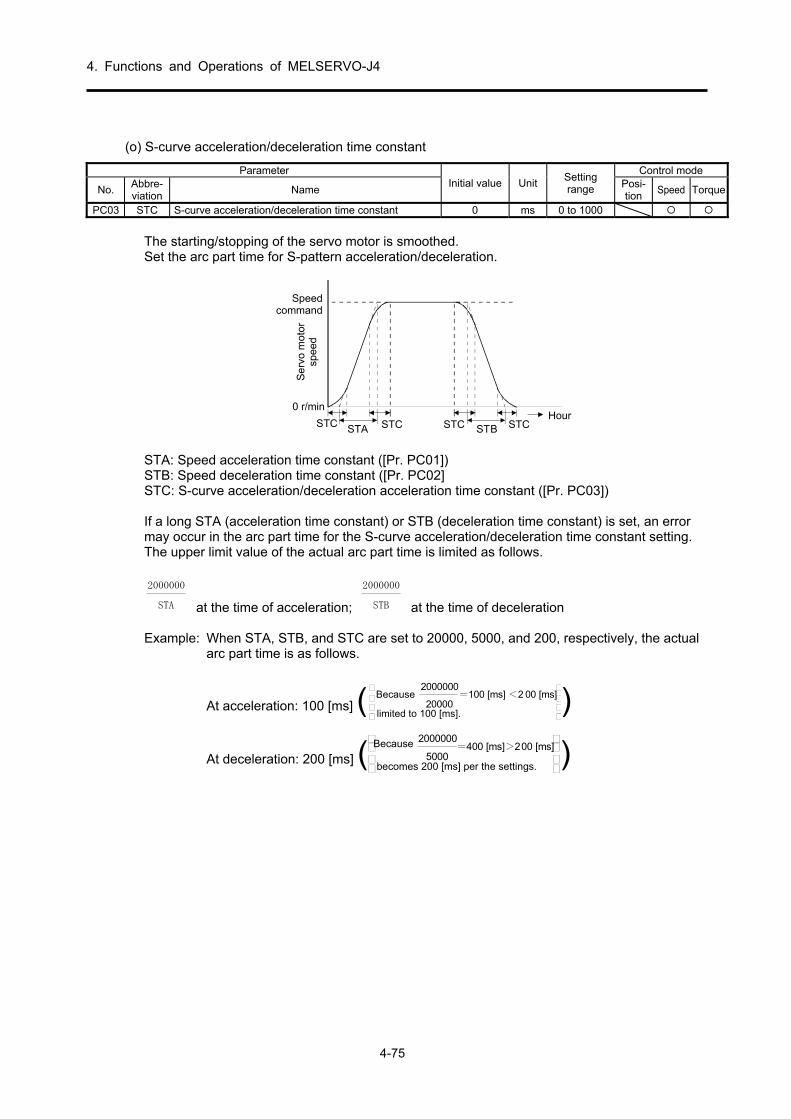
4. Functions and Operations of MELSERVO-J4
4-75
(o) S-curve acceleration/deceleration time constant
Parameter Initial value Unit
Setting range
Control mode
No. Abbre- viation
Name Posi- tion
Speed Torque
PC03 STC S-curve acceleration/deceleration time constant 0 ms 0 to 1000
The starting/stopping of the servo motor is smoothed. Set the arc part time for S-pattern acceleration/deceleration.
0 r/min
STASTC STC STBSTC STC
Speedcommand
Ser
vom
otor
spee
d
Hour
STA: Speed acceleration time constant ([Pr. PC01]) STB: Speed deceleration time constant ([Pr. PC02] STC: S-curve acceleration/deceleration acceleration time constant ([Pr. PC03]) If a long STA (acceleration time constant) or STB (deceleration time constant) is set, an error may occur in the arc part time for the S-curve acceleration/deceleration time constant setting. The upper limit value of the actual arc part time is limited as follows.
STA
2000000
at the time of acceleration; STB
2000000
at the time of deceleration Example: When STA, STB, and STC are set to 20000, 5000, and 200, respectively, the actual
arc part time is as follows.
At acceleration: 100 [ms] (limited to 100 [ms].
00 [ms]=100 [ms] <220000
2000000Because )
At deceleration: 200 [ms] (becomes 200 [ms] per the settings.
00 [ms]=400 [ms]>25000
2000000Because )

4. Functions and Operations of MELSERVO-J4
4-76
(p) Torque command time constant
Parameter Initial value Unit
Setting range
Control mode
No. Abbre-viation
Name Posi- tion
Speed Torque
PC04 TQC Torque command time constant 0 ms 0 to 50000
Set the primary delay filter constant for the torque command.
TQC TQC
Torque
Torque command
After filtering
Hour
TQC: Torque command time constant

4. Functions and Operations of MELSERVO-J4
4-77
4.3.8 Parameter Setting After power-on, initialize the parameter value depending on the operation conditions. The parameters are described in section 4.3.7. Set based on the settings specifications. In particular, make sure to check the parameters described in section 4.3.7 (2). [Operating procedure] Parameter mode transition Shifting to each parameter mode is done with the "MODE" button, and pressing the "UP" or "DOWN" button will transition the display as follows.
[Pr.PB01]
[Pr.PA02]
[Pr.PA01] [Pr.PD01]
[Pr.PD02]
[Pr.PD47]
[Pr.PD48]
[Pr.PC01]
[Pr.PC02]
[Pr.PC79]
[Pr.PC80]
[Pr.PB02]
[Pr.PB63]
[Pr.PB64]
[Pr.PA31]
[Pr.PA32]
[Pr.PE01]
[Pr.PE02]
[Pr.PE63]
[Pr.PE64]
[Pr.PF01]
[Pr.PF02]
[Pr.PF47]
[Pr.PF48]
MODE
UP
DOWN
To status display mode
From alarm modeBasic settingparameters
Gain/filter parametersExtension setting
parametersI/O settingparameters
Extension setting 2parameters
Extension setting 3parameters
For use with training machine

4. Functions and Operations of MELSERVO-J4
4-78
……
……
……
パラメータ番号を表示します。"UP"ボタンまたは"DOWN"ボタンを押すと番号が変わり ます。
"SET"ボタンを2回押します。
指定したパラメ ータの設定値が点滅します。
"UP"ボタンを2回押します。
点滅中は設定値を変更できます。"UP"ボタンまたは"DOWN"ボタンを使用してく ださい。(_ _ _ 2:速度制御モード )
"SET"ボタンを押して確定します。
Displays the parameter number.Pressing the "UP" button or "DOWN" button will change theparameter number.
Press the "SET" button twice.
Press the "UP" button twice.
Press the "SET" button to confirm the value.
The set value of the specified parameter starts flashing.
The set value can be changed while it is flashing.
Use the "UP" or "DOWN" button.(_ _ _2: Speed control mode)
Press the "UP" or "DOWN" button to move to the next parameter. Changes to parameter number PA01 are enabled when the power is turned OFF once and then ON again after changing the setting value.
[Parameter setting example (setting value is less than 5 digits)] This example shows the operation method after power-on when the servo has been changed to the speed control mode.
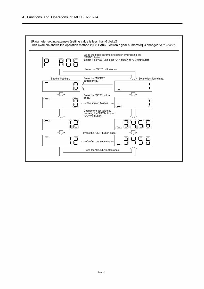
4. Functions and Operations of MELSERVO-J4
4-79
画面が点滅します。
"MODE"ボタンを押して基本パラメ ータの画面にします。"UP"ボタンまたは"DOWN"ボタンを押して [Pr.PA06]を選択してく ださい。
"SET"ボタンを1回押します。
"SET"ボタンを1回押します。
上1桁の設定
"UP"ボタンまたは"DOWN"ボタンで設定値を変更します。
"SET"ボタンを1回押します。
設定値を確定します。
"MODE"ボタンを1回押します。
"MODE"ボタンを1回押します。
下4桁の設定
…… ……
…… …
Go to the basic parameters screen by pressing the"MODE" button.Select [Pr. PA06] using the "UP" button or "DOWN" button.
Press the "SET" button once.
Set the first digit. Set the last four digits.Press the "MODE"button once.
Press the "SET" buttononce.
Press the "SET" button once.
Change the set value bypressing the "UP" button or"DOWN" button.
The screen flashes.
Confirm the set value.
Press the "MODE" button once.
[Parameter setting example (setting value is less than 6 digits)] This example shows the operation method if [Pr. PA06 Electronic gear numerator] is changed to "123456".
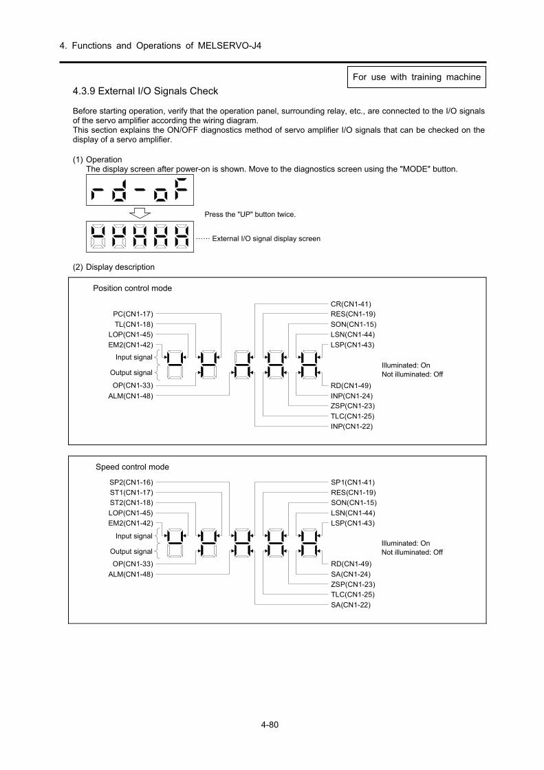
4. Functions and Operations of MELSERVO-J4
4-80
4.3.9 External I/O Signals Check Before starting operation, verify that the operation panel, surrounding relay, etc., are connected to the I/O signals of the servo amplifier according the wiring diagram. This section explains the ON/OFF diagnostics method of servo amplifier I/O signals that can be checked on the display of a servo amplifier. (1) Operation
The display screen after power-on is shown. Move to the diagnostics screen using the "MODE" button.
……
"UP"ボタンを2回押します。
外部入出力信号表示画面
Press the "UP" button twice.
External I/O signal display screen
(2) Display description
Position control mode
点灯: オン
消灯: オフ
PC(CN1-17)
TL(CN1-18)
LOP(CN1-45)
EM2(CN1-42)
入力信号
出力信号
OP(CN1-33)
ALM(CN1-48)
CR(CN1-41)RES(CN1-19)
SON(CN1-15)
LSN(CN1-44)
LSP(CN1-43)
RD(CN1-49)
INP(CN1-24)ZSP(CN1-23)
TLC(CN1-25)
INP(CN1-22)
Input signal
Output signalIlluminated: OnNot illuminated: Off
Speed control mode
点灯: オン
消灯: オフ
SP2(CN1-16)
ST1(CN1-17)
ST2(CN1-18)
LOP(CN1-45)
EM2(CN1-42)
入力信号
出力信号
OP(CN1-33)
ALM(CN1-48)
SP1(CN1-41)
RES(CN1-19)
SON(CN1-15)
LSN(CN1-44)
LSP(CN1-43)
RD(CN1-49)
SA(CN1-24)
ZSP(CN1-23)
TLC(CN1-25)
SA(CN1-22)
Input signal
Output signalIlluminated: OnNot illuminated: Off
For use witFor use with training machine

4. Functions and Operations of MELSERVO-J4
4-81
Torque control mode
点灯: オン
消灯: オフ
SP2(CN1-16)
RS2(CN1-17)
RS1(CN1-18)
LOP(CN1-45)
EM2(CN1-42)
入力信号
出力信号
OP(CN1-33)
ALM(CN1-48)
SP1(CN1-41)
RES(CN1-19)
SON(CN1-15)
RD(CN1-49)
ZSP(CN1-23)
VLC(CN1-25)
Input signal
Output signalIlluminated: OnNot illuminated: Off

4. Functions and Operations of MELSERVO-J4
4-82
4.3.10 Test Operation of Position Control Mode Before starting this operation, implement the test operation and confirm that the machine operates normally. For the power on/off method of the servo amplifier, refer to section 4.3.5 (4).
Test operation of just the servo motor through JOG operation of the
test operation mode
Confirm that the servo amplifier and servo motor operatenormally. Check whether the servo motor rotates correctly using the test operation mode at as low a speed as possible with the servomotor disconnected from the machine. For more on the testoperation mode, refer to section 4.3.13.
Test operation on just the servo motor according to commands
Confirm that the servo motor rotates correctly at the lowestpossible speed using commands from controller. Check that the servo motor rotates with the following procedure. 1) Turn on EM2 (forced stop) and SON (servo-on). When in the
servo-on state, RD (ready) is turned on. 2) Turn on LSP (forward rotation stroke end) and LSN (reverse
rotation stroke end). 3) The servo motor rotates when the pulse train is input from the
controller. After the first low speed command, confirm therotation direction of the servo motor, etc. If movement in the intended direction is not carried out, examine the input signal.
Test operation with the servo motor and machine connected
Interlock the servo motor and the machine, and confirm that themachine operates normally using commands from the controller.Check that the servo motor rotates with the following procedure. 1) Turn on EM2 (forced stop) and SON (servo-on). When in the
servo-on state, RD (ready) is turned on. 2) Turn on LSP (forward rotation stroke end) and LSN (reverse
rotation stroke end). 3) The servo motor rotates when the pulse train is input from the
controller. After the first low speed command, confirm the operationdirection of the machine, etc. If movement in the intendeddirection is not carried out, examine the input signal. Check the status display to confirm that there are no problems in theservo motor speed, the command pulse frequency, the loadfactor, etc.
4) Next, implement automatic operation confirmation using the
controller program.

4. Functions and Operations of MELSERVO-J4
4-83
4.3.11 Test Operation of Speed Control Mode Before starting this operation, implement the test operation and confirm that the machine operates normally. For the power on/off method of the servo amplifier, refer to section 4.3.5 (6).
Test operation of just the servo
motor through JOG operation of thetest operation mode
Confirm that the servo amplifier and servo motor operatenormally. Check whether the servo motor rotates correctly using the testoperation mode at as low a speed as possible with the servo motor disconnected from the machine. For more on the testoperation mode, refer to section 4.3.13.
Test operation on just the servo motor according to commands
Confirm that the servo motor rotates correctly at the lowestpossible speed using commands from controller. Check that the servo motor rotates with the following procedure. 1) Turn on EM2 (forced stop) and SON (servo-on). When in the
servo-on state, RD (ready) is turned on. 2) Turn on LSP (forward rotation stroke end) and LSN (reverse
rotation stroke end). 3) The servo motor rotates when VC (analog speed command)
is input from the controller and ST1 (forward rotation start) orST2 (reverse rotation start) are turned on. After the first lowspeed command, confirm the rotation direction of the servo motor, etc. If movement in the intended direction is not carriedout, examine the input signal.
Test operation with the servo motor and machine connected
Interlock the servo motor and the machine, and confirm that themachine operates normally using commands from the controller.Check that the servo motor rotates with the following procedure. 1) Turn on EM2 (forced stop) and SON (servo-on). When in the
servo-on state, RD (ready) is turned on. 2) Turn on LSP (forward rotation stroke end) and LSN (reverse
rotation stroke end). 3) The servo motor rotates when VC (analog speed command)
is input from the controller and ST1 (forward rotation start) orST2 (reverse rotation start) are turned on. After the first lowspeed command, confirm the operation direction of the machine, etc. If movement in the intended direction is notcarried out, examine the input signal. Check the statusdisplay to confirm that there are no problems in the servomotor speed and load factors, etc.
4) Next, implement automatic operation confirmation using the
controller program.

4. Functions and Operations of MELSERVO-J4
4-84
4.3.12 Test Operation of Torque Control Mode Before starting this operation, implement the test operation and confirm that the machine operates normally. For the power on/off method of the servo amplifier, refer to section 4.3.5 (8).
Test operation of just the servo
motor through JOG operation of thetest operation mode
Confirm that the servo amplifier and servo motor operatenormally. Check whether the servo motor rotates correctly using the test operation mode at as low a speed as possible with the servomotor disconnected from the machine. For more on the testoperation mode, refer to section 4.3.13.
Test operation on just the servo motor according to commands
Confirm that the servo motor rotates correctly at the lowestpossible speed using commands from controller. Check that the servo motor rotates with the following procedure. 1) Turn on SON (servo-on). When in the servo-on state, RD
(ready) is turned on. 2) The servo motor rotates when VTC (analog torque command)
is input from the controller and RS1 (forward rotationselection) or RS2 (reverse rotation selection) are turned on.After the first low torque command, confirm the rotationdirection of the servo motor, etc. If movement in the intended direction is not carried out, examine the input signal.
Test operation with the servo motor and machine connected
Interlock the servo motor and the machine, and confirm that themachine operates normally using commands from the controller.Check that the servo motor rotates with the following procedure. 1) Turn on SON (servo-on). When in the servo-on state, RD
(ready) is turned on. 2) The servo motor rotates when VTC (analog torque command)
is input from the controller and RS1 (forward rotationselection) or RS2 (reverse rotation selection) are turned on.After the first low torque command, confirm the operationdirection of the machine, etc. If movement in the intendeddirection is not carried out, examine the input signal. Check the status display to confirm that there are no problems in theservo motor speed and load factors, etc.
3) Next, implement automatic operation confirmation using the
controller program.

4. Functions and Operations of MELSERVO-J4
4-85
4.3.13 Test Operation Mode
CAUTION
The test operation mode is for confirming servo operation. Do not
use in this operation. If an unexpected operating status arises, stop using EM2 (forced
stop).
POINT
With the test operation mode, the absolute position detection system by DIO
(Set [Pr. PA03] to "_ _ _ 1") cannot be used. MR Configurator2 is required for positioning operation. Test operation cannot be executed without turning off SON (servo-on).
(1) Mode switching The display screen after power-on is displayed. Select JOG operation/motor-less operation using the following procedure. Move to the diagnostics screen using the "MODE" button.
"UP"ボタンを4回押します。
"SET"ボタンを2s以上押します。
この画面になると JOG運転が可能になり ます。
テスト 運転モード になると 点滅します。
……
Press the "UP" button four times.
Once in the test operation mode, it will flash.
Once this screen is displayed,JOG operation will be enabled.
Keep the "SET" button pressed fortwo seconds or more.

4. Functions and Operations of MELSERVO-J4
4-86
(2) JOG operation
POINT
When performing JOG operation, turn on EM2, LSP, and LSN. LSP and LSN
can be turned ON automatically by setting [Pr. PD01] to "_ C _ _".
JOG operation can be executed when there is no command from a controller.
(a) Operation/Drive
The servo motor rotates while the "UP" or "DOWN" button is pressed. Rotation stops if the button is released. When using MR Configurator2, operation conditions can be changed. The following table shows the initial conditions and setting ranges of the operation.
Item Initial setting Setting range
Rotation speed [r/min] 200 0 to permissible instantaneous
speed Acceleration/deceleration
time constant [ms] 1000 0 to 50000
The following table offers an explanation of the buttons.
Button Description
"UP" Rotates in the CCW direction when pressed. Stops when released.
"DOWN" Rotates in the CW direction when pressed. Stops when released.
When performing JOG operation using MR Configurator2, deceleration of the servo motor stops when the USB cable is removed during operation.
(b) Status display The servo status can be confirmed during JOG operation. The display switches to the status display screen if the "MODE" button is pressed while JOG operation is enabled. Execute JOG operation using the "UP" or "DOWN" button while on this screen. The display switches to the following status display screen each time the "MODE" button is pressed and cycles through before returning to the JOG operation enabled status screen. For details on the status display contents, refer to section 4.5.3. The status display screen can be changed using the "UP" or "DOWN" button while in the test operation mode.
(c) Termination of JOG operation Terminate JOG operation by shutting off the power supply once or by pressing the "SET" button for 2 s or more after moving to the next screen by pressing the "MODE" button.

4. Functions and Operations of MELSERVO-J4
4-87
(3) Positioning operation
POINT
MR Configurator2 is required to perform positioning operation. When performing positioning operation, turn on EM2 (forced stop).
Positioning operation can be executed when there is no command from an external controller. (a) Operation/Drive
In the MR Configurator2 menu, click on [Test operation]→[Positioning operation].
②
③
④
⑤ ⑥
⑦
⑧
①
⑨
⑩
⑪ ⑫
⑬
⑭
⑮
(1) Travel distance unit selection Displayed only when the positioning operation screen is started for the first time. Select the pulse travel distance unit.
(2) Motor rotation speed [r/min]
Input the servo motor speed in the "Motor rotation speed" input column. (3) Acceleration/deceleration time constant [ms]
Input the acceleration/deceleration time constant in the "Acceleration/Deceleration time constant" input column.
(4) Travel distance [pulse]
Input the travel distance in the "Travel distance" input column. (5) Automatic ON of LSP, LSN
Click the check box to enable if the external stroke signal is turned on automatically. When not checked, turn on LSN and LSP from outside.

4. Functions and Operations of MELSERVO-J4
4-88
(6) Phase Z signal movement
Move until the initial phase Z signal turns on for the travel distance and travel direction.
(7) Travel distance unit selection
Using the option button, select whether the travel distance set in (4) should be in command pulse units or encoder pulse units. When command input pulse units is selected, movement is done by the value that the electronic gear is multiplied to the travel distance set. When encoder output pulse units is selected, the electronic gear is not multiplied.
(8) Enable repeat operation
To repeat operation, click on the check box. The following table shows the initial setting values and setting ranges of repeat operation.
Item Initial setting Setting range
Repeat pattern Forward rotation
(CCW) → Reverse rotation (CW)
Forward rotation (CCW) → Reverse rotation (CW)
Forward rotation (CCW) → Forward rotation (CCW)
Reverse rotation (CW) → Forward rotation (CCW)
Reverse rotation (CW) → Reverse rotation (CW)
Dwell time [s] 2.0 0.1 to 50.0 Operation frequency [times] 1 1 to 9999
For continuous operation with a repeating pattern/dwell time set as in the table above, click on the "Make the aging function valid" check box.
(9) Servo motor start
The servo motor rotates in the forward direction if the "Forward rotation" button is clicked. The servo motor rotates in the reverse run direction if the "reverse rotation" button is clicked.
(10) Servo motor pause
Rotation of the servo motor pauses if the "Pause" button is clicked during servo motor rotation. This button is enabled during servo motor operation.
(11) Servo motor stop
The servo motor stops if the "Stop" button is clicked during servo motor rotation.
(12) Forced stop
A sudden stop is initiated if the "Forced stop" button is clicked during servo motor rotation. This button is enabled during servo motor operation.
(13) Operating status
Displays the operation status and operation frequency during repeat operation. (14) Axis number
Displays the number of the axis in operation. (15) Closing the positioning operation window
The positioning operation mode is cleared and the window closed if the upper-right "X" button is clicked.
(b) Status display
The status display can be monitored even during positioning operation.

4. Functions and Operations of MELSERVO-J4
4-89
(4) Motor-less operation
The status can be displayed without connecting the servo motor when the output signal is output according to the input device as if the servo motor were actually operating. Use is possible in a sequence check of the upper programmable controllers, etc.
(a) Operation/Drive
Select motor-less operation after turning off SON (servo-on). After that, operate from the outside similar to normal operation.
(b) Start of motor-less operation
After setting [Pr. PC60] to "_ _ _ 1", turn off the power supply and turn it on again. After that, operate from the outside similar to normal operation.
(c) Termination of motor-less operation
Turn off the power supply after setting [Pr. PC60] to "_ _ _ 0" in order to terminate motor-less operation.
(5) Program operation
Positioning operation that combines multiple operation patterns is possible without using a controller. Use after a forced stop has been cleared. Use is possible regardless of whether the servo is on/off or if a controller is connected. Operation is performed on the program operation screen of MR Configurator2. For details, refer to the MR Configurator2 instruction manual.
Operation Screen operation Start Click the "Operation start" button. Stop Click the "Stop" button.
Forced stop Click the "Forced stop" button.
(6) Output signal (DO) forced output
Output signals can be turned on/off forcibly regardless of the status of the servo. Use for output signal wiring checks, etc. Operation is done on the DO forced output screen of MR Configurator2.
4.3.14 Useful Functions for Start-Up/Diagnostics The MR-J4 servo amplifier provides useful functions for start-up and diagnostics besides "external I/O signal checking" in section 4.3.9 and "test operation" in section 4.3.13. The main items are listed below. (1) One-touch tuning: Gain adjustment of the servo amplifier is possible only by push-button operation
or by one click of the MR Configurator2 button. (2) Auto tuning: The servo gain can be automatically adjusted per the moment of inertia of load.
High, medium, low can be selected depending on the condition of the machine. (3) VC automatic offset: The offset of analog input signals such as the speed command can be
automatically corrected. (4) Display of reason for stop: When the motor stops, its cause is shown on a segment of the display. This is
convenient for troubleshooting. (5) DO forced output: Forced output of the digital output signal of the amplifier is performed. This is
convenient for start-up because the external relays, lamps, etc., can be checked. (6) Advanced gain search: This advanced servo adjustment easily allows device performance to be used to
the fullest, even without servo expertise. Note: MR Configurator2 is required when executing advanced gain searches.

4. Functions and Operations of MELSERVO-J4
4-90
Memo

5. Training Machine Operation
5-1
5.1 Overview of AC Servo Training Device
5.1.1 External Appearance/Configuration of Training Machine
機構部
操作パネル1操作パネル2
シーケンサ
Q32SB,Q61SPQ03UDECPU,QD75D1N,QX40
サーボアンプ
MR-J4-10A
Programmablecontroller
Servo amplifier
Operation panel 2
Mechanism
Operation panel 1
負荷用パウダーブレーキ
ZKB-0.06YN
150mm定規
タイミ ングベルト機械原点復帰用
検出器およびド グ
サーボモータ
HG-KR053
Servo motor
Detector and dogfor machine OPR
Powder brakefor load
Timing belt
150 mm regular
主電源N F BMain powersupply NFB

5. Training Machine Operation
5-2
5.1.2 Configuration of Input/Output Operation Panel
操作パネル1
操作パネル2
Operation panel 1
Operation panel 2

5. Training Machine Operation
5-3
5.2 Practical Training of MR-J4 Servo Amplifier
5.2.1 Speed Control
(1) Settings before power-on Always set all operation switches to OFF.
操作パネル2 操作パネル1Operation panel 2 Operation panel 1

5. Training Machine Operation
5-4
(2) Power-on
1) Connect the enclosed 100 V AC cable to match the shape of the outlet (two-pole
parallel or two-pole parallel with grounding). 2) Put the main power supply NFB to ON.
主電源N F B2) Main powersupply NFB
3) Press the main circuit power supply ON button. Power is applied to the main circuit
of servo amplifier.
3) 主回路電源ONボタンMain circuit power supplyON button

5. Training Machine Operation
5-5
(3) Parameter setting
Before operating the training machine, set the parameters to the training device setting values (speed control) per the following table. For how to set the parameters, refer to section 4.3.8.
POINT
To enable a parameter whose abbreviation is preceded by *, turn the power OFF
and then ON after setting the parameter.
(a) Basic setting parameters list
No. Abbre- viation
Name
Control mode Initial value
Unit
Setting value of training machine
Posi-tion
Speed TorquePosition control
Speed control
PA01 *STY Operation mode 1000h 1000 1002
PA02 *REG Regenerative option 0000h 0000 0000 PA03 *ABS Absolute position detection system 0000h 0000 0000 PA04 *AOP1 Function selection A-1 2000h 2000 2000 PA05 *FBP Number of command input pulses per revolution 10000 10000 10000
PA06 CMX Electronic gear numerator (command input pulse magnification numerator)
1 4194304 4194304
PA07 CDV Electronic gear denominator (command input pulse magnification denominator)
1 10000 10000
PA08 ATU Auto tuning mode 0001h 0001 0001 PA09 RSP Auto tuning response 16 16 16 PA10 INP In-position range 100 pulse 100 100 PA11 TLP Forward rotation torque limit 100.0 % 100.0 100.0 PA12 TLN Reverse rotation torque limit 100.0 % 100.0 100.0 PA13 *PLSS Command pulse input form 0000h 0000 0000 PA14 *POL Rotation direction selection 0 0 0
PA15 *ENR Encoder output pulses 4000 pulse/
rev 4000 4000
PA16 *ENR2 Encoder output pulses 2 1 1 1 PA17
For manufacturer setting 0000h 0000 0000
PA18 0000h 0000 0000 PA19 *BLK Parameter writing inhibit 00AAh 00AA 00AA PA20 *TDS Tough drive setting 0000h 0000 0000 PA21 *AOP3 Function selection A-3 0001h 0001 0001 PA22 For manufacturer setting 0000h 0000 0000 PA23 DRAT Drive recorder arbitrary alarm trigger setting 0000h 0000 0000 PA24 AOP4 Function selection A-4 0000h 0000 0000 PA25 OTHOV One-touch tuning overshoot permissible level 0 % 0 0 PA26
For manufacturer setting
0000h 0000 0000 PA27 0000h 0000 0000 PA28 0000h 0000 0000 PA29 0000h 0000 0000 PA30 0000h 0000 0000 PA31 0000h 0000 0000 PA32 0000h 0000 0000

5. Training Machine Operation
5-6
(b) Gain/filter parameters list
No. Abbre- viation
Name Control mode
Initial value
Unit
Setting value of training machine
Posi-tion
Speed TorquePosition control
Speed control
PB01 FILT Adaptive tuning mode (Adaptive filter II)
0000h 0000 0000
PB02 VRFT Vibration suppression control tuning mode (Advanced vibration suppression control II)
0000h 0000 0000
PB03 PST Position command acceleration/deceleration time constant (position smoothing)
0 ms 0 0
PB04 FFC Feed forward gain 0 % 0 0 PB05 For manufacturer setting 500 500 500 PB06 GD2 Load to motor inertia ratio 7.0 times 7.0 7.0 PB07 PG1 Model loop gain 15.0 rad/s 15.0 15.0 PB08 PG2 Position loop gain 37.0 rad/s 37.0 37.0 PB09 VG2 Speed loop gain 823 rad/s 823 823 PB10 VIC Speed integral compensation 33.7 ms 33.7 33.7 PB11 VDC Speed differential compensation 980 980 980 PB12 OVA Overshoot amount compensation 0 0 0 PB13 NH1 Machine resonance suppression filter 1 4500 Hz 4500 4500 PB14 NHQ1 Notch shape selection 1 0000h 0000 0000 PB15 NH2 Machine resonance suppression filter 2 4500 Hz 4500 4500 PB16 NHQ2 Notch shape selection 2 0000h 0000 0000 PB17 NHF Shaft resonance suppression filter 0000h Note Note PB18 LPF Low-pass filter setting 3141 rad/s 3141 3141
PB19 VRF11 Vibration suppression control 1 - Vibration frequency
100.0 Hz 100.0 100.0
PB20 VRF12 Vibration suppression control 1 - Resonance frequency
100.0 Hz 100.0 100.0
PB21 VRF13 Vibration suppression control 1 - Vibration frequency damping
0.00 0.00 0.00
PB22 VRF14 Vibration suppression control 1 - Resonance frequency damping
0.00 0.00 0.00
PB23 VFBF Low-pass filter selection 0000h 0000 0000 PB24 *MVS Slight vibration suppression control selection 0000h 0000 0000 PB25 *BOP1 Function selection B-1 0000h 0000 0000 PB26 CDP Gain switching selection 0000h 0000 0000
PB27 CDL Gain switching condition 10 kpps]/
[pulse]/[r/min]
10 10
PB28 CDT Gain switching time constant 1 ms 1 1 PB29 GD2B Load to motor inertia ratio after gain switching 7.00 times 7.00 7.00 PB30 PG2B Position loop gain after gain switching 0.0 rad/s 0.0 0.0 PB31 VG2B Speed loop gain after gain switching 0 rad/s 0 0 PB32 VICB Speed integral compensation after gain switching 0.0 ms 0.0 0.0
PB33 VRF1B Vibration suppression control 1 - Vibration frequency after gain switching
100.0 Hz 100.0 100.0
PB34 VRF2B Vibration suppression control 1 - Resonance frequency after gain switching
100.0 Hz 100.0 100.0
PB35 VRF3B Vibration suppression control 1 - Vibration frequency damping after gain switching
0.00 0.00 0.00
PB36 VRF4B Vibration suppression control 1 - Resonance frequency damping after gain switching
0.00 0.00 0.00
PB37
For manufacturer setting
1600 1600 1600 PB38 0.00 0.0 0.0 PB39 0.00 0.0 0.0 PB40 0.00 0.0 0.0 PB41 0000h 0000 0000 PB42 0000h 0000 0000 PB43 0000h 0000 0000 PB44 0.00 0000 0000

5. Training Machine Operation
5-7
No. Abbre- viation
Name Control mode
Initial value
Unit
Setting value of training machine
Posi-tion
Speed TorquePosition control
Speed control
PB45 CNHF Command notch filter 0000h 0000 0000 PB46 NH3 Machine resonance suppression filter 3 4500 Hz 4500 4500 PB47 NHQ3 Notch shape selection 3 0000h 0000 0000 PB48 NH4 Machine resonance suppression filter 4 4500 Hz 4500 4500 PB49 NHQ4 Notch shape selection 4 0000h 0000 0000 PB50 NH5 Machine resonance suppression filter 5 4500 Hz 4500 4500 PB51 NHQ5 Notch shape selection 5 0000 0000 0000
PB52 VRF21 Vibration suppression control 2 - Vibration frequency
100.0 Hz 100.0 100.0
PB53 VRF22 Vibration suppression control 2 - Resonance frequency
100.0 Hz 100.0 100.0
PB54 VRF23 Vibration suppression control 2 - Vibration frequency damping
0.00 0.00 0.00
PB55 VRF24 Vibration suppression control 2 - Resonance frequency damping
0.00 0.00 0.00
PB56 VRF21B Vibration suppression control 2 - Vibration frequency after gain switching
0.0 Hz 0.0 0.0
PB57 VRF22B Vibration suppression control 2 - Resonance frequency after gain switching
0.0 Hz 0.0 0.0
PB58 VRF23B Vibration suppression control 2 - Vibration frequency damping after gain switching
0.00 0.00 0.00
PB59 VRF24B Vibration suppression control 2 - Resonance frequency damping after gain switching
0.00 0.00 0.00
PB60 PG1B Model loop gain after gain switching 0.0 rad/s 0.0 0.0 PB61
For manufacturer setting
0.0 0.0 0.0 PB62 0000h 0000 0000 PB63 0000h 0000 0000 PB64 0000h 0000 0000
Note: An arbitrary value is set automatically.

5. Training Machine Operation
5-8
(c) Extension setting parameters list
No. Abbre- viation
Name Control mode
Initial value
Unit
Setting value of training machine
Posi-tion
Speed TorquePosition control
Speed control
PC01 STA Acceleration time constant 0 ms 0 0 PC02 STB Deceleration time constant 0 ms 0 0 PC03 STC S-curve acceleration/deceleration time constant 0 ms 0 0 PC04 TQC Torque command time constant 0 ms 0 0 PC05 SC1 Internal speed command 1 100 r/min 100 100
Internal speed limit 1 PC06 SC2 Internal speed command 2 500 r/min 500 500
Internal speed limit 2 PC07 SC3 Internal speed command 3 1000 r/min 1000 1000
Internal speed limit 3 PC08 SC4 Internal speed command 4 200 r/min 200 200
Internal speed limit 4 PC09 SC5 Internal speed command 5 300 r/min 300 300
Internal speed limit 5 PC10 SC6 Internal speed command 6 500 r/min 500 500
Internal speed limit 6 PC11 SC7 Internal speed command 7 800 r/min 800 800
Internal speed limit 7 PC12 VCM Analog speed command maximum speed 0 r/min 0 0
Analog speed limit maximum speed PC13 TLC Analog torque command maximum output 100.0 % 100.0 100.0 PC14 MOD1 Analog monitor 1 output 0000h 0002 0002 PC15 MOD2 Analog monitor 2 output 0001h 0001 0001 PC16 MBR Electromagnetic brake sequence output 0 ms 0 0 PC17 ZSP Zero speed 50 r/min 50 50 PC18 *BPS Alarm history clear 0000h 0000 0000 PC19 *ENRS Encoder output pulses selection 0000h 0000 0000 PC20 *SNO Station number setting 0 Station 0 0 PC21 *SOP RS-422 communication function selection 0000h 0000 0000 PC22 *COP1 Function selection C-1 0000h 0000 0000 PC23 *COP2 Function selection C-2 0000h 0000 0000 PC24 *COP3 Function selection C-3 0000h 0000 0000 PC25 For manufacturer setting 0000h 0000 0000 PC26 *COP5 Function selection C-5 0000h 0000 0000 PC27 *COP6 Function selection C-6 0000h 0000 0000 PC28
For manufacturer setting 0000h 0000 0000
PC29 0000h 0000 0000 PC30 STA2 Acceleration time constant 2 0 ms 0 0 PC31 STB2 Deceleration time constant 2 0 ms 0 0 PC32 CMX2 Command input pulse multiplication numerator 2 1 1 1 PC33 CMX3 Command input pulse multiplication numerator 3 1 1 1

5. Training Machine Operation
5-9
No. Abbre- viation
Name Control mode
Initial value
Unit
Setting value of training machine
Posi-tion
Speed TorquePosition control
Speed control
PC34 CMX4 Command input pulse multiplication numerator 4 1 1 1 PC35 TL2 Internal torque limit 2 100.0 % 100.0 100.0 PC36 *DMD Status display selection 0000h 0000 0000 PC37 VCO Analog speed command offset 0 mV 0 0
Analog speed limit offset PC38 TPO Analog torque command offset 0 mV 0 0
Analog torque limit offset PC39 MO1 Analog monitor 1 offset 0 mV 0 0 PC40 MO2 Analog monitor 2 offset 0 mV 0 0 PC41
For manufacturer setting 0 0 0
PC42 0 0 0 PC43 ERZ Error excessive alarm detection level 0 rev 0000 0000 PC44
For manufacturer setting
0000h 0000 0000 PC45 0000h 0000 0000 PC46 0 0000 0000 PC47 0 0000 0000 PC48 0 0000 0000 PC49 0 0000 0000 PC50 0000h 0000 0000 PC51 RSBR Forced stop deceleration time constant 100 ms 100 100 PC52
For manufacturer setting 0 0 0
PC53 0 0 0
PC54 RSUP1 Vertical axis freefall prevention compensation amount
0 0.0001 rev
0 0
PC55
For manufacturer setting
0 0 0 PC56 100 100 100 PC57 0000h 0000 0000 PC58 0 0 0 PC59 0000h 0000 0000 PC60 *COPD Function selection C-D 0000h 0000 0000 PC61
For manufacturer setting
0000h 0000 0000 PC62 0000h 0000 0000 PC63 0000h 0000 0000 PC64 0000h 0000 0000 PC65 0000h 0000 0000 PC66 0000h 0000 0000 PC67 0000h 0000 0000 PC68 0000h 0000 0000 PC69 0000h 0000 0000 PC70 0000h 0000 0000 PC71 0000h 0000 0000 PC72 0000h 0000 0000 PC73 0000h 0000 0000 PC74 0000h 0000 0000 PC75 0000h 0000 0000 PC76 0000h 0000 0000 PC77 0000h 0000 0000 PC78 0000h 0000 0000 PC79 0000h 0000 0000 PC80 0000h 0000 0000

5. Training Machine Operation
5-10
(d) I/O setting parameters list
No. Abbre- viation
Name Control mode
Initial value
Unit
Setting value of training machine
Posi-tion
Speed TorquePosition control
Speed control
PD01 *DIA1 Input signal automatic on selection 1 0000h 0C00 0C00 PD02 For manufacturer setting 0000h 0000 0000 PD03 *DI1L Input device selection 1L 0202h 0202 0202 PD04 *DI1H Input device selection 1H 0002h 0002 0002 PD05 *DI2L Input device selection 2L 2100h 2100 2100 PD06 *DI2H Input device selection 2H 0021h 0021 0021 PD07 *DI3L Input device selection 3L 0704h 0700 0700 PD08 *DI3H Input device selection 3H 0007h 0007 0007 PD09 *DI4L Input device selection 4L 0805h 0505 0505 PD10 *DI4H Input device selection 4H 0008h 0000 0000 PD11 *DI9 Input device selection 5L 0303h 0303 0303 PD12 *DI5H Input device selection 5H 0003h 0003 0003 PD13 *DI6L Input device selection 6L 2006h 0606 0606 PD14 *DI6H Input device selection 6H 0020h 0006 0006 PD15 For manufacturer setting 0000h 0000 0000 PD16 0000h 0000 0000 PD17 *DI8L Input device selection 8L 0A0Ah 0800 0800 PD18 *DI8H Input device selection 8H 0000h 0008 0008 PD19 *DI9L Input device selection 9L 0B0Bh 2000 2000 PD20 *DI9H Input device selection 9H 0000h 0020 0020 PD21 *DI10L Input device selection 10L 2323h 2323 2323 PD22 *DI10H Input device selection 10H 0023h 0023 0023 PD23 *DO1 Output device selection 1 0004h 0002 0002 PD24 *DO2 Output device selection 2 000Ch 000C 000C PD25 *DO3 Output device selection 3 0004h 0004 0004 PD26 *DO4 Output device selection 4 0007h 0007 0007 PD27 For manufacturer setting 0003h 0003 0003 PD28 *DO6 Output device selection 6 0002h 0002 0002 PD29 *DIF Input filter setting 0004h 0004 0004 PD30 *DOP1 Function selection D-1 0000h 0000 0000 PD31 For manufacturer setting 0000h 0000 0000 PD32 *DOP3 Function selection D-3 0000h 0000 0000 PD33 For manufacturer setting 0000h 0000 0000 PD34 DOP5 Function selection D-5 0000h 0000 0000

5. Training Machine Operation
5-11
(e) Extension setting 2 parameters ([Pr. PE_ _ ])
No. Abbre- viation
Name Control mode
Initial value
Unit
Setting value of training machine
Posi-tion
Speed TorquePosition control
Speed control
PE41 EOP3 Function selection E-3 0000h 0000 0000
(f) Extension setting 3 parameters ([Pr. PF_ _ ])
No. Abbre- viation
Name Control mode
Initial value
Unit
Setting value of training machine
Posi-tion
Speed TorquePosition control
Speed control
PF21 DRT Drive recorder switching time setting 0 [s] 0 0 PF22 For manufacturer setting 200 200 200 PF23 OSCL1 Vibration tough drive - Oscillation detection level 50 [%] 50 50 PF24 *OSCL2 Vibration tough drive function selection 0000h 0000 0000 PF25 CVAT Instantaneous power failure tough drive -
Detection time 200 [ms]
200 200
PF26 For manufacturer setting 0 0 0 PF27 0 0 0 PF28 0 0 0 PF29 0000h 0000 0000 PF30 0 0 0 PF31 FRIC Machine diagnosis function - Friction judgment
speed 0 [r/min]
0 0
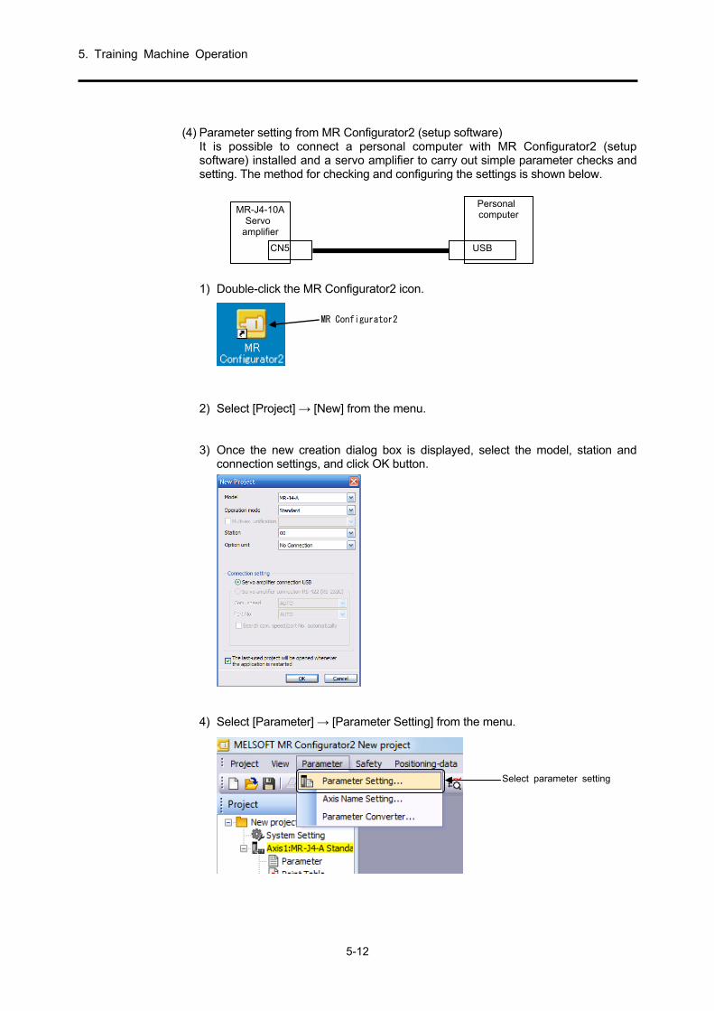
5. Training Machine Operation
5-12
(4) Parameter setting from MR Configurator2 (setup software)
It is possible to connect a personal computer with MR Configurator2 (setup software) installed and a servo amplifier to carry out simple parameter checks and setting. The method for checking and configuring the settings is shown below.
1) Double-click the MR Configurator2 icon.
MR Configurator2
2) Select [Project] → [New] from the menu. 3) Once the new creation dialog box is displayed, select the model, station and
connection settings, and click OK button.
4) Select [Parameter] → [Parameter Setting] from the menu.
MR-J4-10A Servo
amplifier
CN5
Personal computer
USB
Select parameter setting

5. Training Machine Operation
5-13
5) The following parameter setting window opens, and parameter reading, writing,
or referencing can be done. Set the training machine parameters.

5. Training Machine Operation
5-14
(5) Operation
(a) Internal 3-speed operation
1) Operate according to the following procedure and confirm that the forward and reverse speed rotations are as per the internal speed command values 1 to 3 (parameter number PC05 to PC07). The speed can be confirmed on the display on the front of the servo amplifier (5-digit, 7-segment Human Machine Interface (HMI)) or on the MR Configurator2 monitor on the personal computer.
サーボオン ON → 正転始動 ON → 速度選択1 ON → 速度選択2ON → 速度選択1OFF → 正転始動 OFF
逆転始動 ON → 速度選択1 ON → 速度選択2ON → 速度選択1OFF → 逆転始動 OFF
パラメータ
No.PC05100r/minで回転
パラメータ
No.PC07100 0r/min
で回転
パラメータ
No.PC06500r/minで回転
Reverserotationstart
Servo-on Speedselection 1
Speedselection 1
Parameternumber PC05
Rotating at100 r/min
Parameternumber PC07
Rotating at1000 r/min
Parameternumber PC06
Rotating at500 r/min
Speedselection 1
Speedselection 1
Speedselection 2
Speedselection 2
Forwardrotationstart
Reverserotationstart
Forwardrotationstart
2) Change the internal speed command value from 1 to 3 (parameter number PC05 to PC07) and confirm.
(b) External analog speed command (VC) operation
Operation can be performed through VC input that sets the internal 3 speeds (speed selection 1, speed selection 2) to OFF. 1) Set the forward rotation start or reverse rotation start switch to ON and
confirm that the speed can be varied by turning the analog speed command potentiometer.
* When the motor rotates with speed command zero, this does not occur at the time
of operation by internal speed command due because of the input offset of the external speed command signal. In such cases, the motor rotation can be stopped by the method in Section 5.2.1 (5) (c) 4).

5. Training Machine Operation
5-15
(c) Setting confirmation according to various parameters (For Parameter details, refer to
section 4.3.7.) 1) Confirmation of acceleration/ deceleration time constant
Confirm the operation by setting the acceleration time constant (parameter number PC01) and the deceleration time constant (parameter number PC02).
Setting example ······ Parameter number PC01:0 → 1000 (1 second) Parameter number PC02:0 → 2000 (2 seconds)
2) Confirmation of S-curve acceleration/deceleration time constant Confirm the operation by setting the acceleration time constant (parameter number PC01), the deceleration time constant (parameter number PC02), and the S-curve acceleration/deceleration time constant (parameter number PC03).
For details, refer to section 4.3.7 (2) (o). 3) Confirmation of torque limit value
Set the internal torque limit (parameter number PA11/PA12).
Setting example ······ Forward rotation torque limit (parameter number PA11): 100% → 33% (Torque is limited to 1/3 the maximum torque, with the output torque restricted to no more than the rated torque.)
The analog torque limit potentiometer is enabled when the torque limit selection switch is turned ON.
4) Adjustment of VC offset By setting the analog speed command offset (parameter number PC37), it is adjusted in such a way that the motor does not rotate when the command speed voltage is 0 V.
Setting example ······ Analog speed command (parameter number PC37): 0 mV → mV (When forward rotation start is ON, a minus value is set when rotation is in the CCW direction.)
5) Adjustment of analog monitor offset Set the analog monitor ch. 1 offset (parameter number PC39) and correct the monitor output meter.
6) Monitor output setting
The monitor output contents can be changed by setting the analog monitor 1 output (parameter number PC14).
Setting example ······ 0002: Motor speed (+8 V/maximum speed) 0003: Generated torque (+8 V/maximum torque)

5. Training Machine Operation
5-16
7) Status display setting
The status display shown at power-on is selected by setting the status display selection (parameter number PC36).
Setting example ······ 100: Cumulative feedback pulses
101: Servo motor speed 8) Confirmation of various status displays
1) Using a load-setting device, confirm the display contents of the peak load ratio, effective load ratio, etc., while the motor is operating.
2) Confirm the output of speed command F, rotation speed r, and the speed meter (meter pointer fluctuation) by varying the analog speed command maximum speed (parameter number. PC12) from 0 to 2000 with a 10 V command.

5. Training Machine Operation
5-17
5.2.2 Position Control
(1) Settings before power-on Always set all operation switches to OFF.
操作パネル2 操作パネル1Operation panel 2 Operation panel 1
(2) Power-on Turn on the power by referring to section 5.2.1 (2).

5. Training Machine Operation
5-18
(3) Parameter setting
Before operating the training machine, set the parameters to the training device setting values (position control) in section 5.2.1 (3).
(4) Operation
(a) Servo-on Turn on the servo by setting the servo-on (SON) to ON.
(b) JOG operation
1) Set the manual/auto switching switch to the manual side. 2) If the forward movement JOG button is turned to ON, the motor will rotate to the
forward movement side (counterclockwise direction). (Only while the button is ON)
3) If the reverse movement JOG button is turned ON, the motor will rotate to the reverse movement side (clockwise direction). (Only while the button is ON)
(c) Automatic operation
Execute the home position return before automatic operation.
1) Set the manual/auto switching switch to the manual side.
2) When the home position return button is set to ON, the motor returns to the home position. For the home position return operation, refer to section 3.5.2. With automatic operation, turn the switch for manual/automatic switching to the automatic side.
3) If the continuous operation/one-cycle operation switch is set to one-cycle operation and the start button is pressed, operation with the pattern shown in the following figure is implemented once. Press the stop button to stop the operation.
4) If the continuous operation/one-cycle operation switch is set to continuous operation and the start button is pressed, operation with the pattern shown in the following figure is implemented repeatedly. Press the stop button to stop the operation.
-500r/min
10r/min
-10r/min
移動距離(単位mm)
0
50 50 50 50 75 75 75 75100 50 100 150 150 150
逆
A A正
逆 逆 逆 逆 逆
A A正 A A正 A A正 A A B B C正 正
-1000r/min
-2000r/min
500r/min
1000r/min
2000r/min
Travel distance (unit: mm)
ForwardReverse Reverse Reverse Reverse Reverse
ReverseForward Forward Forward Forward Forward
Note: For A, B, and C, dwell time A = 500 ms, B = 1 s, C = 2 s.

5. Training Machine Operation
5-19
(d) Timing belt mechanism and home position operation
The specifications of the mechanical part (timing belt mechanism) for this training machine are as follows. 1) Specifications of timing belt mechanism
No. Item Specifications
1 Belt length L = 550mm (one revolution)
2 Number of pulley teeth on the servo motor side
Z1 = 20
3 Number of pulley teeth on the powder brake side
Z2 = 40
4 Number of belt teeth Z3 = 110
5 Pulley moment of inertia on the servo motor side
JP1 = 0.109 kg cm2
6 Pulley moment of inertia on the powder brake side
JP2 = 0.719 kg cm2
7 Moment of inertia on the powder brake Ja = 0.61 kg cm2
8 Moment of inertia of the servo motor itself JM = 0.045 kg cm2
9 Belt travel distance per motor rotation ∆S = 100 mm
10 Feedback pulse of the motor Pf0 = 4194304 p/rev
<Clipping data> Find the load moment of inertia at motor shaft JL.
2212
aP2P1L
2
61.0719.0109.0
)/Z(Z
J+J+J=J
0.44 kg cm2
The ratio of moment of inertia of the motor and load is JL/JM = 0.44/0.045 9.8 times.
2) In the home position
operation, when the machine OPR switch ON action is repeated 11 times, the reference point is set as shown in the figure on the right. In other words, the reference points shown in the figure on the right match 1 out of 11 times.
定規の長さ
黄色マーク(基準点)
赤色マーク(基準点)Z1=20 Z2=40
Z3=110
Specified length 150mm
Yellow mark(Reference point)
Red mark(Reference point)
Timing belt
∆S = 100 mm/rev
4194304/rev
Deviationcounter
Commandpulse
Multiplyingfactor
Electronicgear
Servomotor
CMX/CDV=1/10 to 4000
Pf0
Max. 4000 kpps(4 Mpps)
Command pulsePositioning
controller
QD75D1N
fc1
∆0
×4
Pc fc ∆c(fc0)
SM
PLG
A
2
11
100
550
S
L=n

5. Training Machine Operation
5-20
(e) Operation confirmation by various parameter settings (For Parameter details, refer to
section 4.3.7.) 1) Electronic gear settings and concepts (parameter number PA06, PA07)
Investigate whether a per-pulse belt travel distance ∆ c = 0.001 mm (1 μm) unit is possible.
rotationmotor per ΔS distance lBelt trave
Δlc pulse 1in belt by the traveleddistance × Pfo pulsefeedback Motor ratiogear Electronic =
CDV
CMX
3125
131072
12500
524288
100
001.04194304===
2) With an electronic gear ratio of 131072/3125, find fc when the motor speed is 3000 r/min. Investigate whether a per-pulse belt travel distance ∆c = 0.001 mm (1 μm) unit is possible.
r/min30004194304
/312513107260f
Pf0
CMX/CDV60fcN
C===
4000kppskpps50003125/13107260
30004194304fC >==
The maximum command frequency of positioning device QD75D1N is 4000 kpps (4 Mpps)Because the maximum command frequency is exceeded, the settings are disabled.
3) Investigate whether a per-pulse belt travel distance ∆c = 0.05 mm (50 μm) unit is
possible.
125
262144
2500
5242880
100
05.04194304ratiogear Electronic ===
CDV
CMX
With an electronic gear ratio of 262144/125, find fc when the motor speed is 3000 r/min.
4000kppskpps100125/26214460
30004194304fc <==
The maximum command frequency of positioning device QD75D1N is 4000 kpps (4 Mpps).There is no problem even at 6000 r/min because 200 kpps < 4000 kpps, which means the maximum command frequency is not exceeded.
* In this training device, the feed length for each pulse is 0.01 mm.
100004194304
10001.04194304==
CDV
CMX
Command pulse multiplication numerator (Parameter number PA06): 4194304 Set command pulse multiplication denominator (parameter number PA07): 10000.
4) Set the in-position range (parameter number PA10). 5) Set the position loop gain (parameter number PB07/PB08).

5. Training Machine Operation
5-21
5.3 Operation Status Adjustment
5.3.1 Adjustment of Servo Amplifier Unit
The following table shows the gain adjustment carried out in the servo amplifier units. Implement "Auto tuning mode 1" at the beginning for gain adjustment. When satisfactory adjustment is not obtained, implement "Auto tuning mode 2" followed by "Manual mode".
(1) Gain adjustment mode explanation
Gain adjustment mode Parameter number
PA08 setting Load to motor inertia ratio
estimation Automatically set
parameter Manually set parameter
Auto tuning mode 1 (Initial value)
0001 Normal estimation GD2 ([Pr. PB06]) PG1 ([Pr. PB07]) PG2 ([Pr. PB08]) VG2 ([Pr. PB09]) VIC ([Pr. PB10])
RSP ([Pr. PA09])
Auto tuning mode 2 0002 Fix to the value of [Pr. PB06] PG1 ([Pr. PB07]) PG2 ([Pr. PB08]) VG2 ([Pr. PB09]) VIC ([Pr. PB10])
GD2 ([Pr. PB06]) RSP ([Pr. PA09])
Manual mode 0003 GD2 ([Pr. PB06]) PG1 ([Pr. PB07]) PG2 ([Pr. PB08]) VG2 ([Pr. PB09]) VIC ([Pr. PB10])
2 gain adjustment mode 1 (interpolation mode)
0000 Normal estimation GD2 ([Pr. PB06]) PG2 ([Pr. PB08]) VG2 ([Pr. PB09]) VIC ([Pr. PB10])
PG1 ([Pr. PB07]) RSP ([Pr. PA09])
2 gain adjustment mode 2 0004 Fix to the value of [Pr. PB06] PG2 ([Pr. PB08]) VG2 ([Pr. PB09]) VIC ([Pr. PB10])
GD2 ([Pr. PB06]) PG1 ([Pr. PB07]) RSP ([Pr. PA09])

5. Training Machine Operation
5-22
(2) Sequence of adjustment and usage of modes
2ゲイン調整モード1(補間モード )
2軸以上で補間する?
運転中の負荷変動が大きい?
開始
終了
Yes
No
Yes
No
Yes
No
No
Yes
ワンタ ッ チ調整
Yes
Yes
Yes
エラー処置可能?
処置実施
調整OK?
正常終了?
2 ゲイン調整モード 2
マニュアルモード
オート チューニングモード 1
Yes
調整OK?
オート チューニングモード 2
No
NoNo
調整OK?
調整OK?
No
Start
Interpolate with2 or more axes?
Is there high loadfluctuation during
operation?
One-touch tuning Execute the action
Is error action possible? Auto tuning mode 1
Auto tuning mode 2
Adjustment OK?
Adjustment OK?
Adjustment OK?
Manual mode
2 gain adjustment mode 2
Normal termination?
Adjustment OK?
End
2 gain adjustment mode 1(Interpolation mode)

5. Training Machine Operation
5-23
5.3.2 One-Touch Tuning
One-touch tuning can be implemented using MR Configurator2 or with push-button operation. The following parameters are automatically adjusted in one-touch tuning.
List of parameters automatically adjusted by one-touch tuning
Parameter Abbreviation Name Parameter Abbreviation Name
PA08 ATU Auto tuning mode PB14 NHQ 1 notch shape selection 1 PA09 RSP Auto tuning response PB15 NH2 Machine resonance
suppression filter 2
PB01 FILT Adaptive tuning mode (adaptive filter II)
PB16 NHQ2 Notch shape selection 2 PB18 LPF Low-pass filter setting
PB02 VRFT
Vibration suppression control tuning mode (advanced vibration suppression control II)
PB19 VRF11 Vibration suppression control 1 - Vibration frequency
PB20 VRF12 Vibration suppression control 1 - Resonance frequency
PB03 PST
Position command acceleration/deceleration time constant (position smoothing)
PB21 VRF13 Vibration suppression control 1 - Vibration frequency damping
PB22 VRF14 Vibration suppression control 1 - Resonance frequency damping
PB06 GD2 Load to motor inertia ratio PB23 VFBF Low-pass filter selection PB07 PG1 Model loop gain PB47 NHQ3 Notch shape selection 3 PB08 PG2 Position loop gain PB48 NH4 Machine resonance
suppression filter 4 PB09 VG2 Speed loop gain PB49 NHQ4 Notch shape selection 4 PB10 VIC Speed integral compensation PB51 NHQ5 Notch shape selection 5 PB12 OVA Overshoot amount
compensation PE41 EOP3 Function selection E-3
PB13 NH1 Machine resonance suppression filter 1
(1) Flow of one-touch tuning
(a) When MR Configurator2 is used Implement one-touch tuning with the following procedure.
Start
To start up the system, refer to section 4.3.1.
Start out-touch tuning of MR Configurator2.
Select the response mode (high mode, basic mode, low mode) from the one-touch tuningscreen of MR Configurator2.
Press the start button to execute one-touch tuning. Press the start button while the motor is running. Ifone-touch tuning ends normally, the parameters given in the table above are automatically adjusted.
Run (rotate) the servo motor with an external controller.(One-touch tuning does not operate while the servo motor is stopped.)
End
Start up the system
Operation
Select response mode
Execute one-touch tuning
Activate one-touch tuning
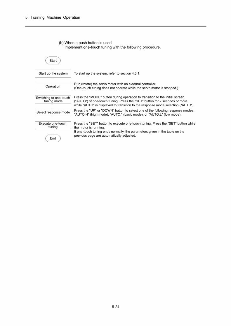
5. Training Machine Operation
5-24
(b) When a push button is used
Implement one-touch tuning with the following procedure.
Start
Start up the system To start up the system, refer to section 4.3.1.
Run (rotate) the servo motor with an external controller.(One-touch tuning does not operate while the servo motor is stopped.)
Press the "UP" or "DOWN" button to select one of the following response modes:"AUTO.H" (high mode), "AUTO." (basic mode), or "AUTO.L" (low mode).
Press the "SET" button to execute one-touch tuning. Press the "SET" button whilethe motor is running.If one-touch tuning ends normally, the parameters given in the table on theprevious page are automatically adjusted.
Press the "MODE" button during operation to transition to the initial screen("AUTO") of one-touch tuning. Press the "SET" button for 2 seconds or morewhile "AUTO" is displayed to transition to the response mode selection ("AUTO").
Operation
Select response mode
End
Execute one-touchtuning
Switching to one-touchtuning mode

5. Training Machine Operation
5-25
(2) One-touch tuning display transition/operation method
(a) When MR Configurator2 is used
1) Selection of response mode Select the response mode (3 types) of one-touch tuning from the one-touch tuning screen of MR Configurator2.
Response mode Explanation
High mode Response mode for devices with high machine rigidity.
Basic mode Response mode for standard machines.
Low mode Response mode for devices with low machine rigidity.
For the response mode targets, refer to the following table.
Response mode Machine characteristics
Arm robot
High-accuracymachine tool
devices
General machinetool carrier
machine
InserterMounterBonder
Standard value of the corresponding machine
Slow response
Fast response
ResponselevelLow mode Basic mode High mode

5. Training Machine Operation
5-26
2) Implementation of one-touch tuning
If a response mode is selected in 1) and the start button is pressed while the motor is being driven, one-touch tuning will start. If the start button is pressed when the motor has stopped, "C002" or "C004" is displayed in the error code status. (For error codes, refer to the "List of error codes at the time of one-touch tuning" table under 4) on the next page.)
The adjustment progress is displayed in the progress display screen as follows during one-touch tuning. One-touch tuning is complete when the progress is 100%.
Adjustment parameters are written to the servo amplifier when one-touch tuning is completed. "0000" is displayed in the error code status. After completion of adjustment, the settling time and overshoot amount are displayed in the adjustment result.
3) Stopping of one-touch tuning
If the stop button is pressed during one-touch tuning, one-touch tuning is stopped. If one-touch tuning is stopped, "C0000" is displayed in the error code status.

5. Training Machine Operation
5-27
4) In case of error
When an adjustment error occurs during adjustment, one-touch tuning is terminated. At that time, because the error code is displayed in the error code status, confirm the cause of the adjustment error occurrence.
List of error codes at the time of one-touch tuning
Error code Name Description Action
C000 Cancellation during adjustment
"SET" of the stop button or the push button has been pressed during one-touch tuning.
C0001 Excessive overshoot The overshoot is higher than the value set in [Pr. PA10 In-position range].
Increase the in-position setting.
C002 Servo off during adjustment Implementation of one-touch tuning in the servo-off status in was attempted.
Implement one-touch tuning after the servo is on.
C003 Control mode error Implementation of one-touch tuning with torque control as the control mode was attempted.
Implement one-touch tuning after changing the control mode from the controller to position control or speed control.
C004 Time-out
1. The one-cycle time during operation has exceeded 30 s.
Lower the one-cycle time during operation to 30 s or less.
2. The command speed is low. Change the servo motor rotation speed to 100 r/min or more.
3. The operation interval of continuous operation is short.
Ensure that the stopping interval during operation is 200 ms.
C005 Load to motor inertia ratio estimation error
1. Estimation of the load to motor inertia ratio at the time of one-touch tuning has failed.
Operate so that the following estimation conditions are fulfilled. The time until reaching 2000 r/min is
the deceleration time constant for 5 s or less.
The rotation speed is 150 r/min or more.
The load to motor inertia ratio is ×100 or less.
The acceleration/deceleration torque is 10% or more than the rated torque.
2. Estimation of the load to motor inertia ratio could not be carried out due to the oscillation effect.
Implement one-touch tuning after setting to an auto tuning mode where load to motor inertia ratio estimation is not carried out as follows. Select "Auto tuning mode 2 (_ _ _ 2)",
"Manual mode (_ _ _ 3)", or "2 gain adjustment mode 2 (_ _ _ 4)" in "Gain adjustment mode selection" of "[Pr. PA08]".
Set [Pr. PB06 Load to motor inertia ratio] accurately according to the manual setting.
COOF Invalid one-touch tuning "One-touch tuning function selection" of [Pr. PA21] is "Invalid (_ _ _0)".
Set the parameter to "Valid (_ _ _1)".
5) In case of alarm
When a servo alarm occurs during one-touch tuning, one touch tuning stops. 6) In case of warning
When a warning occurs whereby operation can continue during one-touch tuning, one-touch tuning is continued and executed. When a warning occurs whereby operation cannot continue during one-touch tuning, one-touch tuning is stopped.
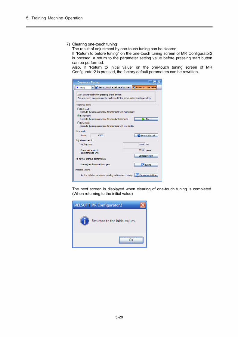
5. Training Machine Operation
5-28
7) Clearing one-touch tuning
The result of adjustment by one-touch tuning can be cleared. If "Return to before tuning" on the one-touch tuning screen of MR Configurator2 is pressed, a return to the parameter setting value before pressing start button can be performed. Also, if "Return to initial value" on the one-touch tuning screen of MR Configurator2 is pressed, the factory default parameters can be rewritten.
The next screen is displayed when clearing of one-touch tuning is completed. (When returning to the initial value)

5. Training Machine Operation
5-29
(b) When a push button is used
1) Selection of response mode Select the response mode (three types) of one-touch tuning using the "UP" or "DOWN" button. For the response mode targets, refer to (2) (a) 1) of this section.
DOWNUP
Response mode selection display
Low mode: Response mode for devices with low machine rigidity.
Basic mode: Response mode for standard machines.
How mode: Response mode for devices with high machine rigidity.
2) Implementation of one-touch tuning If a response mode is selected in 1) and the "SET" button is pressed, one-touch tuning starts.
During one-touchtuning
End display
Shows the progress status of one-touch tuning from 0% to 100%.During one-touch tuning, the decimal point moves from right to left and is illuminated.During one-touch tuning, the screen can transition to the status display by pressingthe "MODE" button.
When one-touch tuning ends, the parameters that are automatically adjusted duringone-touch tuning are written to the servo amplifier.

5. Training Machine Operation
5-30
3) Stopping of one-touch tuning
Stop symbol display
Error code
Initial screen
2 s interval
The screen transitions to the initial screen when the "SET" button is pressed.
When the screen has transitioned to the one-touch tuning mode, the one-touch tuningmode can be stopped by pressing the "SET" button while any item is displayed.
The stop symbol and error code "C 000" (cancellation during tuning) are alternatelydisplayed at 2 s intervals.
4) In case of error Stop symbol display
Error code
Initial screen
2 s interval
The screen transitions to the initial screen when the "SET" button is pressed.
If an error occurs during one-touch tuning, one-touch tuning is terminated and the stop symboland error codes "C 001" to "C 00F" are displayed alternately at 2 s intervals.
To check the cause of the error, refer to the table in section (1) (a) (1).
5) In case of alarm During one-touch tuning
Alarm display
If an alarm occurs during one-touch tuning, one-touch tuning is terminated and the screentransitions to the alarm display.

5. Training Machine Operation
5-31
6) In case of warning
During one-touch tuning
Alarm display (warning)
If a warning occurs during one-touch tuning, the screen transitions to the alarm displayand displays a warning.If the warning is a kind that allows operation to continue, the one-touch tuningoperation will be continued.
7) Clearing of one-touch tuning For the parameters that can be cleared, refer to the table in section 5.3.2. The result of one-touch tuning can be overwritten to the factory default parameters using the clear mode. The one-touch tuning result can be returned to the parameter setting value before adjustment using the back mode.
1) Press the "MODE" button and transition to the initial screen "AUTO" of one-
touch tuning. 2) Select the clear mode or the back mode using the "UP" or "DOWN" button.
DOWNUP
One-touch tuning clear mode selection
Auto mode
Clear mode
Back mode
One-touch tuning is cleared when the "SET" button is pressed for 2 s or more.
The screen transitions to the initial screen when one-touch tuning is completely cleared.
One-touch tuning clear mode display (initial value restoration)
Initial screen
Executes the selected one-touch tuning clear mode. During execution, the one-touchtuning clear mode symbol flashes for 3 s.

5. Training Machine Operation
5-32
(3) Cautions during one-touch tuning
(a) One-touch tuning is not possible in the torque control mode. (b) One-touch tuning is not possible when an alarm occurs or a when a warning
whereby operation cannot be continued occurs. (c) One-touch tuning can be implemented during test operation mode executions
with "".
One-touch tuning method
Test operation mode
Output signal (DO) forced output
JOG operation
Positioning operation
Motor-less operation
Program operation
Using MR Configurator2 ¡ Operation by push button

5. Training Machine Operation
5-33
5.3.3 Auto Tuning
(1) Auto tuning mode The characteristics (load to motor inertia ratio) of the machine are estimated in real time, and a real-time auto tuning function that automatically sets the appropriate gain corresponding to that value is built-in to the servo amplifier. Gain adjustment of the servo amplifier can be easily carried out by this function.
(a) Auto tuning mode 1 The servo amplifier has auto tuning mode 1 set by default. The load to motor inertia ratio of the machine is normally estimated by this mode, and the appropriate
gain is automatically set. The parameters that can be automatically adjusted by auto tuning mode 1 are as shown in the
following table.
Parameter number Abbre-viation
Name
PB06 GD2 Load to motor inertia ratio PB07 PG1 Model loop gain PB08 PG2 Position loop gain PB09 VG2 Speed loop gain PB10 VIC Speed integral compensation
POINT
If auto tuning mode 1 does not satisfy the following conditions, it may not
operate normally. The time until reaching 2000 r/min is the deceleration time constant for 5 s or
less. The rotation speed is 150 r/min or more. The load to motor inertia ratio is ×100 or less. The acceleration/deceleration torque is 10% or more than the rated torque.
For machines with operating conditions where a disturbance torque can be rapidly added during acceleration/deceleration or with large gutters at the extremes, auto tuning will not function normally. In such cases, adjust the gain with auto tuning mode 2 or the manual mode.
(b) Auto tuning mode 2 Auto tuning mode 2 is used when normal gain adjustment cannot be carried out in auto tuning mode 1. Because estimation of the load to motor inertia ratio is not carried out in this mode, set an accurate value of the load to motor inertia ratio (parameter number PB06). The parameters that can be automatically adjusted by auto tuning mode 2 are as shown in the following table.
Parameter number Abbre-viation
Name
PB07 PG1 Model loop gain PB08 PG2 Position loop gain PB09 VG2 Speed loop gain PB10 VIC Speed integral compensation
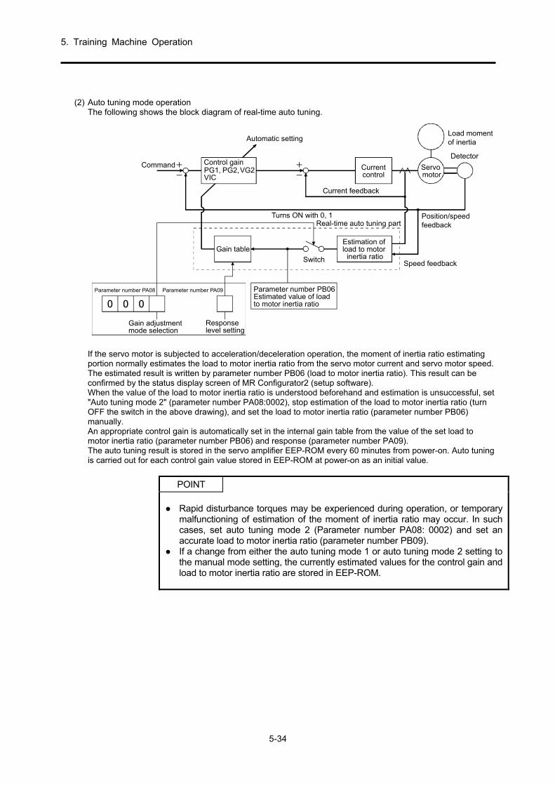
5. Training Machine Operation
5-34
(2) Auto tuning mode operation
The following shows the block diagram of real-time auto tuning.
PG1, PG2,VG2VIC
+
-
+
-
0 0 0
Command Control gain
Automatic setting
Turns ON with 0, 1Real-time auto tuning part
Current feedback
Detector
Position/speedfeedback
Speed feedback
Estimation ofload to motor
inertia ratioGain table
Gain adjustmentmode selection
Responselevel setting
Parameter number PA08 Parameter number PA09 Parameter number PB06Estimated value of loadto motor inertia ratio
Switch
Servomotor
Load momentof inertia
Currentcontrol
If the servo motor is subjected to acceleration/deceleration operation, the moment of inertia ratio estimating portion normally estimates the load to motor inertia ratio from the servo motor current and servo motor speed. The estimated result is written by parameter number PB06 (load to motor inertia ratio). This result can be confirmed by the status display screen of MR Configurator2 (setup software). When the value of the load to motor inertia ratio is understood beforehand and estimation is unsuccessful, set "Auto tuning mode 2" (parameter number PA08:0002), stop estimation of the load to motor inertia ratio (turn OFF the switch in the above drawing), and set the load to motor inertia ratio (parameter number PB06) manually. An appropriate control gain is automatically set in the internal gain table from the value of the set load to motor inertia ratio (parameter number PB06) and response (parameter number PA09). The auto tuning result is stored in the servo amplifier EEP-ROM every 60 minutes from power-on. Auto tuning is carried out for each control gain value stored in EEP-ROM at power-on as an initial value.
POINT
Rapid disturbance torques may be experienced during operation, or temporary
malfunctioning of estimation of the moment of inertia ratio may occur. In such cases, set auto tuning mode 2 (Parameter number PA08: 0002) and set an accurate load to motor inertia ratio (parameter number PB09).
If a change from either the auto tuning mode 1 or auto tuning mode 2 setting to the manual mode setting, the currently estimated values for the control gain and load to motor inertia ratio are stored in EEP-ROM.

5. Training Machine Operation
5-35
(3) Adjustment procedure using auto tuning
Because auto tuning is enabled by default, only by operation of the servo motor can an appropriate gain that conforms to the machine automatically set. If necessary, adjustment is completed only by changing the response setting value. The following shows the adjustment procedure.
END
Yes
No
Yes
No
No
Yes
Auto tuning adjustment
Repeated acceleration/deceleration
Set to auto tuning mode 2(parameter number PA08: 0002) andmanually set the load to motor inertiaratio (parameter number PB06).
Adjust the response level so that thedesired response level is achievedwithout generation of vibration.
Repeated acceleration/deceleration
Required performanceachieved?
To manual mode
The auto tuningconditions are not satisfied.
(Difficult to estimate the loadto motor inertia ratio
stability)
Is the estimatedvalue of load to motor inertia
ratio stable?

5. Training Machine Operation
5-36
(4) Auto tuning mode response setting
Set the response of the entire servo system with [Pr. PA09]. A higher response setting will result in a shorter settling time with better compliance characteristics for the command, but a setting too high will cause vibrations. Therefore, set so that the desired response is obtained in a range where vibrations do not occur. When a high response cannot be set up to the prescribed response because of a machine resonance that exceeds 100 Hz, the machine resonance can be suppressed by selecting filter tuning mode in [Pr. PB01] and machine resonance suppression filter in [Pr. PB13] to [Pr.PB16] and [Pr. PB46] to [Pr. PB51]. A high response setting is also possible by suppressing the machine resonance.
Parameter number PA09
Response level setting
[Pr.PA09]
1 2.7 67.1
2 22 75.6
3 23 85.2
4 24 95.9
5 25 108.0
6 26 121.7
7 27 137.1
8 28 154.4
9 29 173.9
10 30 195.9
11 31 220.6
12 32 248.5
13 33 279.9
14 34 315.3
15 35 355.1
16 36 400.0
17 37 446.6
18 38 501.2
19 52.9 571.5
20 59.6 642.7
21
3.6
4.9
6.6
10.0
11.3
12.7
14.3
16.1
18.1
20.4
23.0
25.9
29.2
32.9
37.0
41.7
47.0
39
40
Set value Set valueResponselevel
Slowresponse
Mediumresponse
Mediumresponse
Fastresponse
Target machineresonance frequency
[Hz]
Target machineresonance frequency
[Hz]
Responselevel
Machine characteristics Machine characteristics

5. Training Machine Operation
5-37
5.3.4 Manual Mode
When satisfactory adjustment is not possible with auto tuning, manual adjustment is carried out for all of the gain.
POINT
When machine resonance occurs, suppression of the machine resonance is
possible with the filter tuning mode (parameter number PB01) and the machine resonance suppression filter (parameter number PB13 to PB16). (Refer to section 5.4.2.)
(1) With speed control
(a) Parameter Parameters that are used for gain adjustment are as follows.
Parameter number Abbre-viation
Name
PB06 GD2 Load to motor inertia ratio PB07 PG1 Model loop gain PB09 VG2 Speed loop gain PB10 VIC Speed integral compensation
(b) Adjustment procedure
Procedure Operation Description
1 Rough adjustment is carried out by auto tuning.
2 Change the settings for auto tuning to manual mode (parameter number PA08:0003).
3 Set the estimated value in the load to motor inertia ratio. (It is not necessary to change the setting when the value estimated by auto tuning is accurate.)
4 Set the model loop gain low. Set the speed integral compensation high.
5 The speed loop gain is high in ranges without vibrations and abnormal noise, and if vibrations occur, it returns slightly.
Set the speed loop gain high.
6 The speed integral compensation is low in ranges where no vibrations are output, and if vibrations occur, it returns slightly.
Set a low time constant for the speed integral compensation.
7 The model loop gain increases, and if overshooting occurs, it returns slightly.
Set the model loop gain high.
8
When the gain cannot be increased due to machine system resonance and the prescribed response cannot be obtained, the response may be increased if procedures 3 to 7 are implemented after suppressing resonance with the adaptive tuning mode and machine resonance suppression filters.
Machine resonance suppression Refer to sections 5.4.1 and 5.4.2.
9 Fine adjustment of each gain is carried out while observing the settling characteristics and the rotation status.
Fine adjustment

5. Training Machine Operation
5-38
(c) Adjustment description
1) Speed loop gain (parameter number PB09) This parameter decides the speed control loop response. If a high value is set, although response will increase, if the setting is too high, the machine will vibrate easily. The response frequency of the actual speed loop is as determined by the following formula.
Speed loop response frequency (Hz) = Speed loop gain set value
(1 + Load to motor inertia ratio) × 2π
2) Speed integral compensation (VIC: Parameter number PB10)
Speed control loop results in proportional integral control so that there is no steady deviation for commands. Set the integral control time constant for speed integral compensation. A higher setting value results in a worse response. However, when the load to motor inertia ratio is high and vibrating elements exist in the machine system, the machine system may vibrate easily if it is not increased to some extent. The targets are as shown in the following formula. Speed integral compensation setting value (ms)
≥ 2000 to 3000
Speed loop gain set value/(1 + Load to motor inertia ratio set value)
(3) Model loop gain (PG1: Parameter number PB07)
This parameter decides the position command response. If the model loop gain is high, even though the compliance characteristics for position command improve, if it is too high, overshooting occurs easily at the settling time.
Model loop gain target ≤
(2) With position control (a) Parameter
Parameters that are used for gain adjustment are as follows.
Parameter number Abbre-viation
Name
PB06 GD2 Load to motor inertia ratio PB07 PG1 Model loop gain PB08 PG2 Position loop gain PB09 VG2 Speed loop gain PB10 VIC Speed integral compensation
×(1 + Load to motor inertia ratio)
Speed loop gain set value
81to
41

5. Training Machine Operation
5-39
(b) Adjustment procedure
Procedure Operation Description
1 Rough adjustment is carried out by auto tuning.
2 Change the settings for auto tuning to manual mode (parameter number PA08:0003).
3 Set the estimated value in the load to motor inertia ratio. (It is not necessary to change the setting when the value estimated by auto tuning is accurate.)
4 Set the model loop gain and position loop gain low. Set the speed integral compensation high.
5 The speed loop gain is high in ranges without vibrations and abnormal noise, and if vibrations occur, it returns slightly.
Set the speed loop gain high.
6 The speed integral compensation is low in ranges where no vibrations are output, and if vibrations occur, it returns slightly.
Set a low time constant for the speed integral compensation.
7 The position loop gain is high, and if vibrations occur, it returns slightly.
Set the position loop gain high.
8 The model loop gain increases, and if overshooting occurs, it returns slightly.
Set the model loop gain high.
9
When the gain cannot be increased due to machine system resonance and the prescribed response cannot be obtained, the response may be increased if procedures 3 to 8 are implemented after suppressing resonance with the adaptive tuning mode and machine resonance suppression filters.
Machine resonance suppression Refer to sections 5.4.1 and 5.4.2.
10 Fine adjustment of each gain is carried out while observing the settling characteristics and the rotation status.
Fine adjustment
(c) Adjustment description
1) Speed loop gain (VG2: Parameter number PB09) This parameter decides the speed control loop response. If a high value is set, although response will increase, if the setting is too high, the machine will vibrate easily. The response frequency of the actual speed loop is as determined by the following formula.
Speed loop response frequency (Hz) = Speed loop gain set value
(1 + Load to motor inertia ratio) × 2π
2) Speed integral compensation (VIC: Parameter number PB10)
Speed control loop results in proportional integral control so that there is no steady deviation for commands. Set the integral control time constant for speed integral compensation. A higher setting value results in a worse response. However, when the load to motor inertia ratio is high and vibrating elements exist in the machine system, the machine system may vibrate easily if it is not increased to some extent. The targets are as shown in the following formula. Speed integral compensation setting value (ms)
≥ 2000 to 3000
Speed loop gain set value/(1 + Load to motor inertia ratio set value)

5. Training Machine Operation
5-40
(3) Position loop gain (PG2: Parameter number PB08)
This parameter decides the response regarding position control loop disturbances. If the position loop gain is high, the change regarding disturbances becomes small, but if the setting is too large, the machine system will vibrate easily.
Position loop gain target ≤
(4) Model loop gain (PG1: Parameter number PB07) This parameter decides the position command response. If the model loop gain is high, even though the compliance characteristics for position command improve, if it is too high, overshooting occurs easily at the settling time.
Model loop gain target ≤
×(1 + Load to motor inertia ratio)
Speed loop gain set value
×(1 + Load to motor inertia ratio)
Speed loop gain set value
81to
41
81to
41

5. Training Machine Operation
5-41
5.3.5 Adjustment Using MR Configurator2
(1) Communication I/F The MELSERVO-J4 Series is equipped with a USB interface in addition to the standard RS-422 interface. Communicable data includes parameter contents (including various gains), monitor-related information (contents such as current, speed, and pulse drop, which can be displayed on the amplifier LED), I/O signals, and alarm displays. The protocols and command-related information required for communication are public, so the software for communication can be created by the user. For USB
CN5
Servo amplifier
Personal computer
To USBconnector
USB cableMR-J3USBCBL3M(Optional)
For RS-422
CN3 CN3 CN3
Personal computer
To RS-232 Cconnector RS-422/232 C converter
Servo amplifier Servo amplifier Servo amplifier

5. Training Machine Operation
5-42
(2) Features of MR Configurator2
MR Configurator2 provides a more useful engineering environment and further improves the setting/start-up adjustment/maintainability efficiency of the servo amplifier. A portion of the new functions is introduced below.
(a) Servo assistant
Complete setup of the servo amplifier just by following the guidance display.
(b) Group parameter settings
Group parameter settings can be easily configured on the parameter setting screen.
The related functions can be easily called with the short-cut buttons.
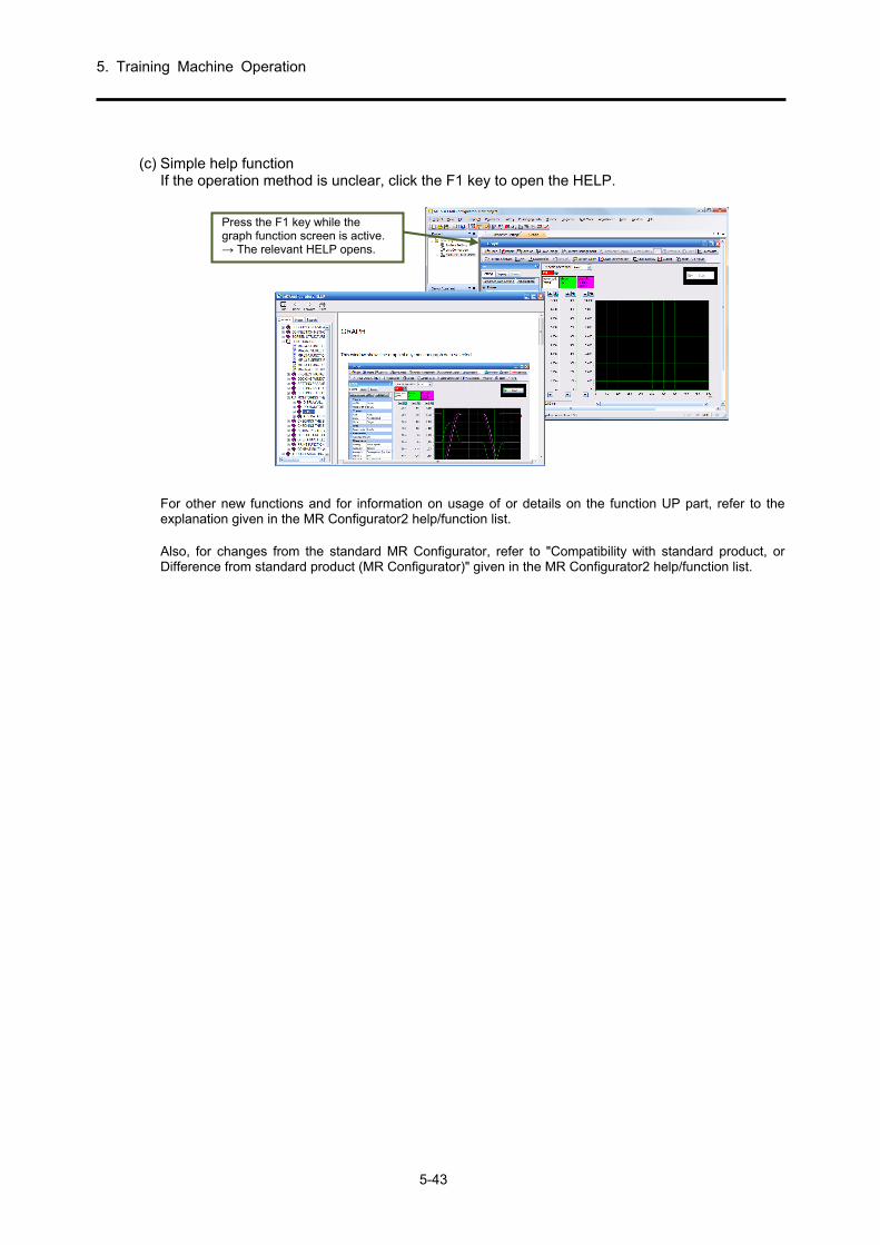
5. Training Machine Operation
5-43
(c) Simple help function
If the operation method is unclear, click the F1 key to open the HELP.
For other new functions and for information on usage of or details on the function UP part, refer to the explanation given in the MR Configurator2 help/function list. Also, for changes from the standard MR Configurator, refer to "Compatibility with standard product, or Difference from standard product (MR Configurator)" given in the MR Configurator2 help/function list.
Press the F1 key while the graph function screen is active. → The relevant HELP opens.
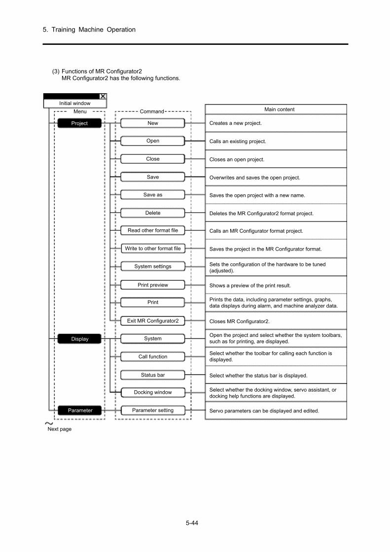
5. Training Machine Operation
5-44
(3) Functions of MR Configurator2
MR Configurator2 has the following functions.
Initial window
Menu
Project
Display
Parameter
Command
New Creates a new project.
Calls an existing project.Open
Closes an open project.Close
Overwrites and saves the open project.Save
Saves the open project with a new name.Save as
Deletes the MR Configurator2 format project.Delete
Calls an MR Configurator format project.Read other format file
Saves the project in the MR Configurator format.Write to other format file
Shows a preview of the print result.Print preview
Closes MR Configurator2.Exit MR Configurator2
Select whether the status bar is displayed.Status bar
Servo parameters can be displayed and edited.Parameter setting
Next page
Select whether the docking window, servo assistant, ordocking help functions are displayed.
Docking window
Select whether the toolbar for calling each function isdisplayed.
Call function
Sets the configuration of the hardware to be tuned(adjusted).
System settings
Prints the data, including parameter settings, graphs,data displays during alarm, and machine analyzer data.
Open the project and select whether the system toolbars,such as for printing, are displayed.
System
Main content

5. Training Machine Operation
5-45
Continue from previous page
Monitor
Diagnostics
Test operation
Menu Command Main content
Next page
Displays each servo status items in numerical values.Batch display
Displays the servo status in a graph format.Graph
Displays the reason why the servo motor is not running.No rotation reason display
Displays the life diagnostics information.Life diagnostics
Executes the JOG operation.JOG operation
Executes the positioning operation.Positioning operation
Executes the motor-less operation.Motor-less operation
Executes the DO forced output.DO forced output
Executes the program operation.Program operation
Displays the start/end of operation, and the alarm andwarnings during operation in a time series format.
Test operation event information
Displays the monitor and parameters related to the linearfunction.
Linear diagnostics
Displays the monitor and parameters related to the fullyclosed function.
Fully closed diagnostics
Displays the system configuration information.System configuration display
Checks the absolute position data in the absolute positiondetection system.
ABS data display
Displays the monitor data when an alarm or warningoccurs in the current amplifier.
Data display in the event of an alarm
Displays the details when an alarm or warning occurs inthe current amplifier.Displays the history of past alarms or warnings in a listformat.
Alarm display
Displays the status of the I/O signal, analog monitor, etc.Input/output monitor indicator

5. Training Machine Operation
5-46
Continue from previous page
Menu Command Main content
Adjustment
Tool
Window
Help
Sets and adjusts the gain parameters.Tuning
Executes the machine analyzer.Machine analyzer
Executes the advanced gain search.Advanced gain search
Displays the screens in a cascade format.Cascade
Displays the screens in a vertical tiled format.Tile vertically
Displays the screens in a horizontal tiled format.Tile horizontally
Minimizes and arranges the screen icons.Arrange icons
Closes all the displayed windows.Close all windows
Displays the version information.Version information
Displays the MR Configurator2 help.MR Configurator2 help
Displays the homepage of Mitsubishi Electric FA.Mitsubishi Electric FA Homepage
Sets the enable/disable settings for the machine unitconversion display and the unit/pulse/travel distance usedin unit conversion.
Machine unit conversion settings
Retrieves the parameter setting range from the connectedamplifier and updates the MR Configurator2 data file.
Parameter setting range update

5. Training Machine Operation
5-47
(4) Graph ([Monitor] - [Graph] Menu) In the graph window, optional monitor graph data is displayed as a graph.
Operating procedure (1) Waveform section to be output
Select Motor speed in Analog CH1
↓ Torque in Analog CH2 Pulse drop+ in Analog CH3 INP in Digital
(2) Collection condition setting ↓ Set INP on the falling edge in
the trigger (3) Collection of waveform data
50 ms/Div of horizontal axis sampling
↓ Click the button. Training machine automatic operation start (Switch ON the start button on the operation panel.)
(4) Observe the collected waveform ↓ Adjustment of horizontal axis
scale (5) Saving the waveform data
↓ Click the menu.
(6) Graph completion * Details can be confirmed using
Help.
(5) Tuning ([Adjustment]-[Tuning] menu) In the tuning window, adjust the gain parameter and configure the settings so that operating is possible according to the objective.
Operating procedure (1) Select Auto tuning mode ↓ Select Auto tuning mode 2 (2) Set the load to motor inertia
ratio ↓ Set to 9.8 times *1 *1: The load inertia moment ratio
is the value calculated in (4) (d) of section 5.2.2.
* Details can be confirmed using
Help.
(2) Collection condition setting
(1) Waveform section to be output
(1) Check
(2) Set the load to motor inertia ratio

5. Training Machine Operation
5-48
(6) Machine analyzer ([Adjustment] - [Machine Analyzer] Menu)
The machine system and frequency features are displayed using relational expressions (Bode plot) for the normal, gain, and phase frequency. Gain indicates the size of the response of the machine system for the torque input, and phase indicates the phase delay of the speed response for the torque input. If the machine system is rigid and there is no resonance point, gain is linear. There is generally some resonance point in the machine system, and the frequency or size of the resonance can be measured by the machine analyzer. The following figure is a measurement example when a resonance of 638 Hz exists in the machine system. If the speed gain continues to increase, the machine will vibrate easily at that resonance frequency because the gain increases in the resonance point and the response of the machine for the input torque increases.
Operating procedure (1) Set the machine analyzer ↓ Leave as default (2) Run the machine analyzer
↓ Click the
button. (3) Observing the waveform data ↓ Resonance point, anti-
resonance point check (4) Filter setting ↓ Not required if not resonating (5) Saving the file
↓ Click the menu.(6) Finish * Details can be confirmed using
Help.
Yellow line: Anti-resonance point; Red line: Resonance point
If the resonance frequency of the machine system can be measured, then the frequency of the machine resonance suppression filter (parameter number PB13, parameter number PB15) can be decided based on this result, and the machine vibration can be controlled when gain increases.
Torque
Loading machine
Transmissionmechanism
(1) Check

5. Training Machine Operation
5-49
(7) Test operation (positioning operation) ([Test Operation]-[Positioning Operation] menu)
Positioning operation can be executed once when there is no command from an external controller. (a) Operation/Drive
When performing positioning operation, connect EMG-DOCOM. When the "Forward rotation"/"Reverse rotation" button on the MR Configurator2 is clicked, the servo motor rotates and travels for the set travel distance before stopping. The operation conditions can be changed on MR Configurator2. The initial operating values and setting ranges are given in the following table.
Item Initial setting Setting range
Motor rotation speed [r/min]
200 1 to 6900
Acceleration and deceleration time constant
[ms] 1000 0 to 50000
Travel distance [pulse] Value obtained from the
amplifier 0 to 2147483647
An explanation of the keys is given in the following table.
Button Description
"Forward rotation"
If this button is clicked, the motor rotates in the CCW direction.
"Reverse rotation"
If this button is clicked, the motor rotates in the CW direction.
"Pause"
If this button is clicked during work, the work is paused. If the "Pause" button is clicked once more, the remaining distance is deleted. To restart the operation, click the same button that initiated the operation.
Forward rotation(CCW)
Reverse rotation (CW)
If the communication cable comes off, the servo motor will stop suddenly.
(b) Status display
The status of the servo can be displayed on the monitor even during positioning operation.
POINT MR Configurator2 is required to perform positioning operation.

5. Training Machine Operation
5-50
(8) Test operation (program operation) ([Test Operation]-[Program Operation] menu)
(a) Program example
Press the <Start (G)> button to automatically set the SON to ON and start operation simultaneously.
Execute 3 times.
Se
rvom
otorsp
eed
Operation 2Rotation speed: 2000r/minAcceleration/decelerationtime constant: 1200msTravel distance: -10000pulse
Operation 1Rotation speed: 1000r/minAcceleration/decelerationtime constant: 1200msTravel distance: 12000pulse
Describe the program in single-byte characters and enter a line break (press the <Enter> key)at the end of the line.
Operation 1
Operation 2
ProgramRepeat the program 3 times up to STOP.
Travel 12000 pulses in the CCW direction.
Wait 10 seconds for the next operation.Set the command rotation speed to 2000 r/min.Travel 100000 pulses in the CW direction.
Set the acceleration/deceleration time constant to 1200 ms.
Set the command rotation speed to 1000 r/min.
Hold the execution of the program until theinput signal setting 0 (SON) turns to ON.
The acceleration/deceleration time constant of operation 1 and operation 2 is the same. In this case, there is no need to set the acceleration/deceleration time constant in operation 2. In this way, the operation program only gives the setting value to be changed from the previous operation. Note: For program operation where the "Program Operation" window and other windows (for example,
the "Monitor Batch Display" window) are displayed at the same time, the progress of the program is delayed and the dwell command time becomes longer than the setting value.
Details on the simplified language of the program operation can be checked under Help.

5. Training Machine Operation
5-51
5.4 Special Adjustment Function
POINT
Use of the functions displayed in this section is generally unnecessary. Use these functions when the machine status is unsatisfied according to the adjustment methods from section 5.3.
If there is a specific resonance point in the mechanical system and if the servo system response is increased, the mechanical system may resonate (vibration or abnormal noise) at that resonance frequency. The resonance of the machine system can be controlled by using the machine resonance suppression filter and adaptive tuning.
5.4.1 Filter Setting
In the MR-J4 servo amplifier, the filter settings can be configured as shown in the following figure.
[Pr.PB18] [Pr.PB13] [Pr.PB15] [Pr.PB46]
[Pr.PB49][Pr.PB48]
[Pr.PB17]
[Pr.PE41][Pr.PB50]
PWM M
Commandpulse train
Speed control
Commandfilter
Low-passfilter setting
Load
Servo motor
Encoder
Robust filter
Machineresonance
suppressionfilter 1
Machineresonance
suppressionfilter 2
Machineresonance
suppressionfilter 3
Machineresonance
suppressionfilter 4
Shaft resonancesuppression filter
Machineresonance
suppressionfilter 5
5.4.1.1 Machine Resonance Suppression Filter
POINT
The machine resonance suppression filter is the delay element for the servo system. Because of this, if a mistaken resonance frequency is set, and if the notch characteristics are deepened, vibrations may increase.
If the mechanical resonance frequency is unknown, lower the notch frequency. The point where the resonance is smallest is the optimum notch frequency setting.
A deeper notch depth will have a greater effect in reducing mechanical resonance, but because the phase delay is larger, vibration may increase.
A wider notch depth will have a greater effect in reducing mechanical resonance, but because the phase delay is larger, vibration may increase.
The mechanical characteristics can be assessed in advance with a machine analyzer that uses MR Configurator2. This enables the required notch frequency and the notch characteristics to be determined.
If there is a specific resonance point in the machine system, and the response of the servo system continues to increase, the machine system may vibrate (vibration and acoustic noise) at that resonance frequency. The resonance of the machine system can be controlled by using the machine resonance suppression filter and adaptive tuning. The setting range is from 10 Hz to 4500 Hz.

5. Training Machine Operation
5-52
(1) Working
The machine resonance suppression filter is the filter function (notch filter) that controls the resonance of the machine system by decreasing a specific frequency gain. The frequency (notch frequency) that decreases the gain and the depth and width that decrease the gain can be set.
Mac
hine
syst
emre
spon
sele
vel
Not
chch
arac
teris
tics
Machine resonance point
Frequency
Frequency
Notch width
Notch depth
Notch frequency
At most, the following five machine resonance suppression filters can be set.
Filter Set parameter Precautions Parameters reset by the vibration tough
drive function
Parameters automatically set
by one-touch tuning
Machine resonance suppression filter 1
PB01/PB13/PB14 Automatic adjustment is possible using "Filter tuning mode selection" of [Pr. PB01].
PB13 PB01/PB13/
PB14
Machine resonance suppression filter 2
PB15/PB16 PB15 PB15/PB16
Machine resonance suppression filter 3
PB46/PB47 PB47
Machine resonance suppression filter 4
PB48/PB49
If this filter is enabled, the shaft resonance suppression filter cannot be used. The shaft resonance suppression filter is enabled in the initial setting.
PB48/PB49
Machine resonance suppression filter 5
PB50/PB51
Even if it is set, this filter is disabled when the robust filter is being used. The robust filter is disabled in the initial setting.
PB51

5. Training Machine Operation
5-53
(2) Parameter
(a) Machine resonance suppression filter 1 ([Pr. PB13]/[Pr. PB14]) Set the notch frequency, notch depth, and notch width of machine resonance suppression filter 1 ([Pr. PB13]/[Pr. PB14]). When "Manual setting (_ _ _ 2)" is selected in "Filter tuning mode selection" of [Pr. PB01], the machine resonance suppression filter 1 setting is enabled.
(b) Machine resonance suppression filter 2 ([Pr. PB15]/[Pr. PB16])
Use is possible by enabling (_ _ _ 1) "Machine resonance suppression filter 2 selection" of [Pr. PB16]. The setting method of machine resonance suppression filter 2 ([Pr. PB15]/[Pr. PB16]) is the same as machine resonance suppression filter 1 ([Pr. PB13]/[Pr. PB14]).
(c) Machine resonance suppression filter 3 ([Pr. PB46]/[Pr. PB47])
Use is possible by enabling (_ _ _ 1) "Machine resonance suppression filter 3 selection" of [Pr. PB47]. The setting method of machine resonance suppression filter 3 ([Pr. PB46]/[Pr. PB47]) is the same as machine resonance suppression filter 1 ([Pr. PB13]/[Pr. PB14]).
(d) Machine resonance suppression filter 4 ([Pr. PB48]/[Pr. PB49])
Use is possible by enabling (_ _ _ 1) "Machine resonance suppression filter 4 selection" of [Pr. PB49]. However, when machine resonance suppression filter 4 is enabled, the shaft resonance suppression filter cannot be set. The setting method of machine resonance suppression filter 4 ([Pr. PB48]/[Pr. PB49]) is the same as machine resonance suppression filter 1 ([Pr. PB13]/[Pr. PB14]).
(e) Machine resonance suppression filter 5 ([Pr. PB50]/[Pr. PB51])
Use is possible by enabling (_ _ _ 1) "Machine resonance suppression filter 5 selection" of [Pr. PB51]. However, when the robust filter is enabled (Pr. PE41]: _ _ _ 1), machine resonance suppression filter 5 cannot be used. The setting method of machine resonance suppression filter 5 ([Pr. PB50]/[Pr. PB51]) is the same as machine resonance suppression filter 1 ([Pr. PB13]/[Pr. PB14]).

5. Training Machine Operation
5-54
5.4.1.2 Adaptive Filter II
POINT
The machine resonance frequency that is compatible with adaptive filter II
(adaptive tuning) is approximately 100 Hz to 2.25 kHz. Manually configure the settings for resonance frequencies outside of this range.
When adaptive tuning is executed, vibration signals are forcibly added, which increases the vibration noise.
If adaptive tuning is executed, the machine resonance is detected for a maximum of 10 seconds and a filter is generated. After the filter is generated, it is automatically transferred to the manual mode.
Adaptive tuning generates the most appropriate filter using the currently set control gain. If vibration is generated when the response level settings are raised, execute adaptive tuning again.
Adaptive tuning generates a filter with the most appropriate notch depth for the set control gain. If an additional filter margin is desired for the machine resonance, deepen the notch depth in the manual mode.
If the machine system has complex resonance characteristics, the result might not be obtained.
(1) Working The adaptive filter II (adaptive tuning) is a function that detects the machine resonance of the servo amplifier for a fixed period, and automatically sets the filter characteristics to control the vibration of the machine system. Because the filter characteristics (frequency and depth) are set automatically, there is no need to be aware of the resonance frequency of the machine system.
Mac
hin
esy
stem
resp
onse
leve
lN
otch
dep
th
Not
chd
epth
Ma
chin
esy
ste
mre
spon
sele
vel
Machine resonance point
When machine resonance is highand frequency is low
When machine resonance is lowand frequency is high
Machine resonance point
Frequency
FrequencyNotch frequency Notch frequency
Frequency
Frequency
(2) Parameter
Select the filter tuning setting method of [Pr. PB01 Adaptive tuning mode (adaptive filter II)].
[Pr.PB01]
0
0
1
2
PB13 PB14
0 0
Filter tuning mode selection
Filter tuning mode selection
DisabledAutomatic setting
Manual setting
Automatically set parametersSet value
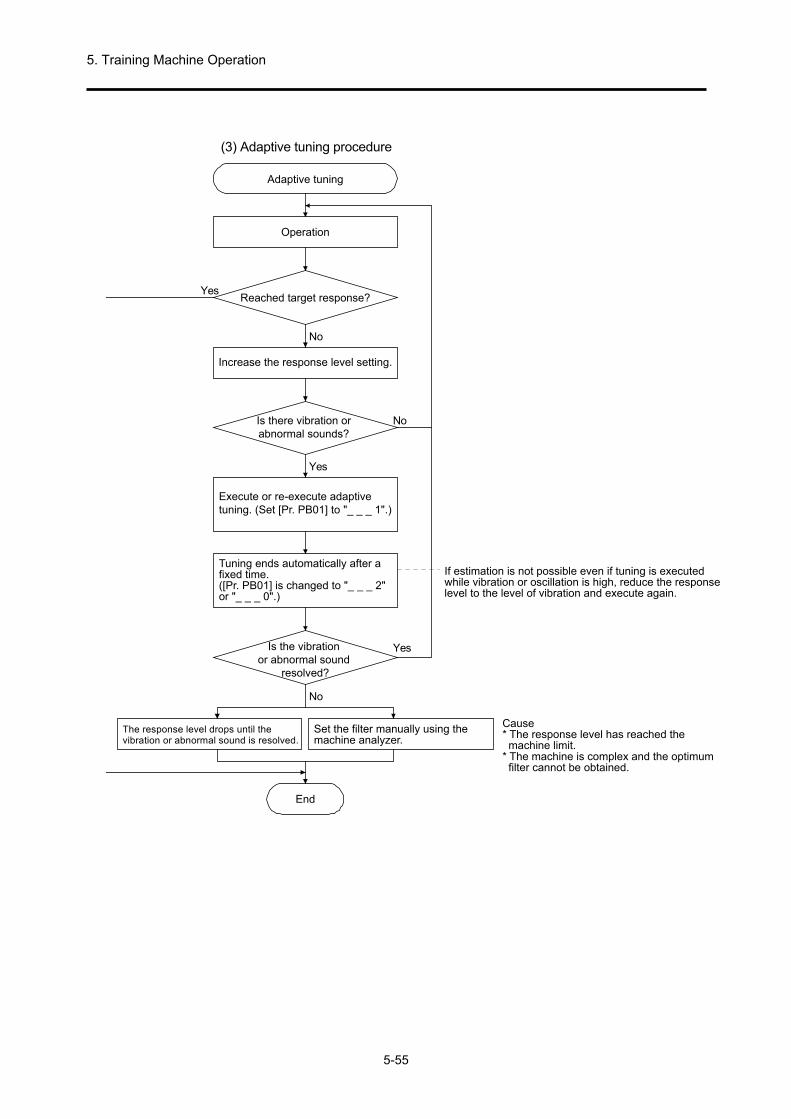
5. Training Machine Operation
5-55
(3) Adaptive tuning procedure
Yes
No
No
Yes
Yes
No
Adaptive tuning
Operation
Reached target response?
Is there vibration orabnormal sounds?
Execute or re-execute adaptivetuning. (Set [Pr. PB01] to "_ _ _ 1".)
Tuning ends automatically after afixed time.([Pr. PB01] is changed to "_ _ _ 2"or "_ _ _ 0".)
If estimation is not possible even if tuning is executedwhile vibration or oscillation is high, reduce the responselevel to the level of vibration and execute again.
Cause* The response level has reached themachine limit.
* The machine is complex and the optimumfilter cannot be obtained.
Set the filter manually using themachine analyzer.
The response level drops until thevibration or abnormal sound is resolved.
Increase the response level setting.
Is the vibrationor abnormal sound
resolved?
End
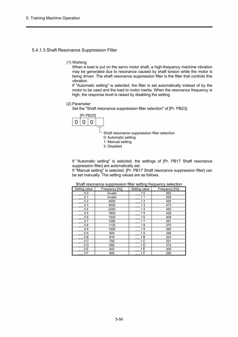
5. Training Machine Operation
5-56
5.4.1.3 Shaft Resonance Suppression Filter
(1) Working
When a load is put on the servo motor shaft, a high-frequency machine vibration may be generated due to resonance caused by shaft torsion while the motor is being driven. The shaft resonance suppression filter is the filter that controls this vibration. If "Automatic setting" is selected, the filter is set automatically instead of by the motor to be used and the load to motor inertia. When the resonance frequency is high, the response level is raised by disabling the setting.
(2) Parameter
Set the "Shaft resonance suppression filter selection" of [Pr. PB23].
[Pr.PB23]
0 0 0
Shaft resonance suppression filter selection0: Automatic setting1: Manual setting2: Disabled
If "Automatic setting" is selected, the settings of [Pr. PB17 Shaft resonance suppression filter] are automatically set. If "Manual setting" is selected, [Pr. PB17 Shaft resonance suppression filter] can be set manually. The setting values are as follows.
Shaft resonance suppression filter setting frequency selection
Setting value Frequency [Hz] Setting value Frequency [Hz] _ _ 0 0 Invalid _ _ 1 0 562 _ _ 0 1 Invalid _ _ 1 1 529 _ _ 0 2 4500 _ _ 1 2 500 _ _ 0 3 3000 _ _ 1 3 473 _ _ 0 4 2250 _ _ 1 4 450 _ _ 0 5 1800 _ _ 1 5 428 _ _ 0 6 1500 _ _ 1 6 409 _ _ 0 7 1285 _ _ 1 7 391 _ _ 0 8 1125 _ _ 1 8 375 _ _ 0 9 1000 _ _ 1 9 360 _ _ 0 A 900 _ _ 1 A 346 _ _ 0 B 818 _ _ 1 B 333 _ _ 0 C 750 _ _ 1 C 321 _ _ 0 D 692 _ _ 1 D 310 _ _ 0 E 642 _ _ 1 E 300 _ _ 0 F 600 _ _ 1 F 290

5. Training Machine Operation
5-57
5.4.1.4 Low-Pass Filter
(1) Working When a ball screw is used and the response level of the servo system is raised, a high-frequency resonance may be generated. To prevent this, the low-pass filter is enabled for the torque command by the initial value. The filter frequency of this low-pass filter is automatically adjusted to the value from the following formula.
Filter frequency ([rad/s]) =VG2
× 10 1+GD2
If "Manual setting (_ _ 1 _)" is selected in "Low-pass filter selection" of [Pr. PB23], manual settings can be configured in [Pr. PB18].
(2) Parameter Set "Low-pass filter selection" of [Pr. PB23].
[Pr.PB23]
000
Low-pass filter selection0: Automatic setting1: Manual setting2: Disabled
5.4.1.5 Advanced Vibration Suppression Control II
POINT
The "Gain adjustment mode selection" of "[Pr. PA08]" is enabled with "Auto
tuning mode 2 (_ _ _ 2)", "Manual mode (_ _ _ 3)", and "2 gain adjustment mode 2 (_ _ _ 4)".
The compatible machine resonance frequency in the vibration suppression control tuning mode is from 1.0 Hz to 100.0 Hz. Manually configure the settings for vibration that is out of this range.
To change the vibration suppression control related parameter, change after stopping the servo motor. Failure to do so may result in the servo motor working unexpectedly.
For positioning operation during vibration suppression control tuning execution, set the stop time period until the vibration is attenuated and stopped.
In some cases, vibration suppression control tuning cannot be estimated correctly if the residual vibration of the servo motor is small.
Vibration suppression control tuning sets the most appropriate parameter using the currently set control gain. Set vibration suppression control tuning again when the response level is raised.
Set [Pr. PA24] to "_ _ _ 1" when using vibration suppression control 2.

5. Training Machine Operation
5-58
(1) Working
Vibration suppression control is used to further suppress vibrations such as work-side vibrations or base shaking. Determine the positioning by adjusting the work on the servo motor side so that the machine does not shake.
t t
Pos
ition
Pos
ition
Servo motor sideLoad side
Vibration suppression control off(Normal control)
Vibration suppression control on
Servo motor sideLoad side
By executing advanced vibration suppression control II ([Pr. PB02 Vibration suppression control 2 tuning mode]), the vibration frequency of the machine system is automatically estimated, and a maximum of two load side vibrations can be suppressed. Also, transition to the manual setting after performing the positioning operation a fixed number of times in the vibration suppression control tuning mode. With the manual setting, vibration suppression control 1 in [Pr. PB19] to [Pr. PB22] and vibration suppression control 2 in [Pr. PB52] to [Pr. PB55] can be adjusted using manual settings.
(2) Parameter
Set [Pr. PB02 Vibration suppression control tuning mode (advanced vibration suppression control II)]. When one vibration suppression control is used, set to "Vibration suppression control 1 tuning mode selection". When two vibration suppression controls are used, set to "Vibration suppression control 1 tuning mode selection" and "Vibration suppression control 2 tuning mode selection".
[Pr.PB02]
0
_ _ _ 0
_ _ _ 1
_ _ _ 2PB19 PB20 PB21 PB22
_ _ 0 _
_ _ 1 _
_ _ 2 _PB52 PB53 PB54 PB55
0
Vibration suppression control 1 tuning mode
DisabledAutomatic setting
Manual setting
DisabledAutomatic setting
Manual setting
Vibration suppression control 1 tuning mode selection Automatically set parameters
Vibration suppression control 2 tuning mode selection Automatically set parameters
Set value
Set value
Vibration suppression control 2 tuning mode

5. Training Machine Operation
5-59
(3) Vibration suppression control tuning procedure
The following figure is for vibration suppression control 1. For vibration suppression control 2, set [Pr. PB02] to "_ _ 1 _" and execute vibration suppression control tuning.
No
Yes
No
No
Yes
Yes
Vibration suppression control tuning
Operation
Reached target response?
Is the vibration atthe workpiece end/device
high?
Increase the response level setting.
Stop operation
Re-start operation
End
Is the vibrationat the workpiece end/device
resolved?
Execute or re-execute vibrationsuppression control tuning.(Set [Pr. PB02] to "_ _ _ 1".)
Tuning ends automatically after afixed number of positioningoperations. ([Pr. PB02] is changedto "_ _ _ 2" or "_ _ _ 0".)
Cause* Estimation cannot be done because the vibrationon the load side is not transmitted to the servomotor side.
* The response level has reached the vibrationfrequency of the model position gain(vibration suppression control limit).
The response level drops until thevibration or abnormal sound at theworkpiece end/device is resolved.
Set the vibration suppression controlmanually from the machine analyzeror the load side vibration waveform.

5. Training Machine Operation
5-60
(4) Vibration suppression control manual mode
POINT
If the vibrations of the load side are not transmitted to the servo motor side, there is no effect even if the vibration frequency of the servo motor side is set.
If the anti-resonance frequency and resonance frequency can be checked by the machine analyzer or the external measuring instrument, vibration suppression performance will be best not when the values are the same but when they are set separately.
If the [Pr. PB07 Model loop gain] value and the relation between the resonance frequency and the anti-resonance frequency is as follows, then there is no effect of vibration suppression control.
With vibration suppression control 1
[Pr. PB19] < 1
(0.9 × [Pr. PB07]) 2π
[Pr. PB20] < 1
(0.9 × [Pr. PB07]) 2π
With vibration suppression control 2 [Pr. PB52] < 5.0 + 0.1 × [Pr. PB07] [Pr. PB53] < 5.0 + 0.1 × [Pr. PB07]
Measure the work-side vibration and the device vibration using the machine analyzer or the external measuring instrument, and then manual adjustment of the vibration suppression control can be done by setting the following parameters.
Setting item Vibration suppression
control 1 Vibration suppression
control 2
Vibration frequency for vibration suppression control
[Pr. PB19] [Pr. PB52]
Resonance frequency for vibration suppression control
[Pr. PB20] [Pr. PB53]
Vibration suppression control - Vibration frequency damping
[Pr. PB21] [Pr. PB54]
Vibration suppression control - Resonance frequency damping
[Pr. PB22] [Pr. PB55]
Procedure 1. Select "Manual setting (_ _ _ 2)" in "Vibration suppression control 1 tuning mode selection" of [Pr. PB02], or select "Manual setting (_ _ _ 2)" in "Vibration suppression control 2 tuning mode selection".
Procedure 2. Set vibration frequency for the vibration suppression control and resonance frequency for the vibration suppression control with the following method.
(a) When the vibration peak can be checked using the machine analyzer or the external measuring instrument with MR Configurator2
1Hz
Gaincharacteristics
Phase
-90deg.
300Hz
Vibration suppressioncontrol 1 - Resonance frequency
Vibration suppressioncontrol 1 - Resonance frequency
(Anti-resonance frequency)[Pr.PB19]
[Pr.PB20]
(Anti-resonance frequency)[Pr.PB52]
Vibration suppression control 2 - Resonance frequency[Pr.PB53]
Resonances of 300 Hz or more are not covered.
Vibration suppression control 2 - Vibration frequency
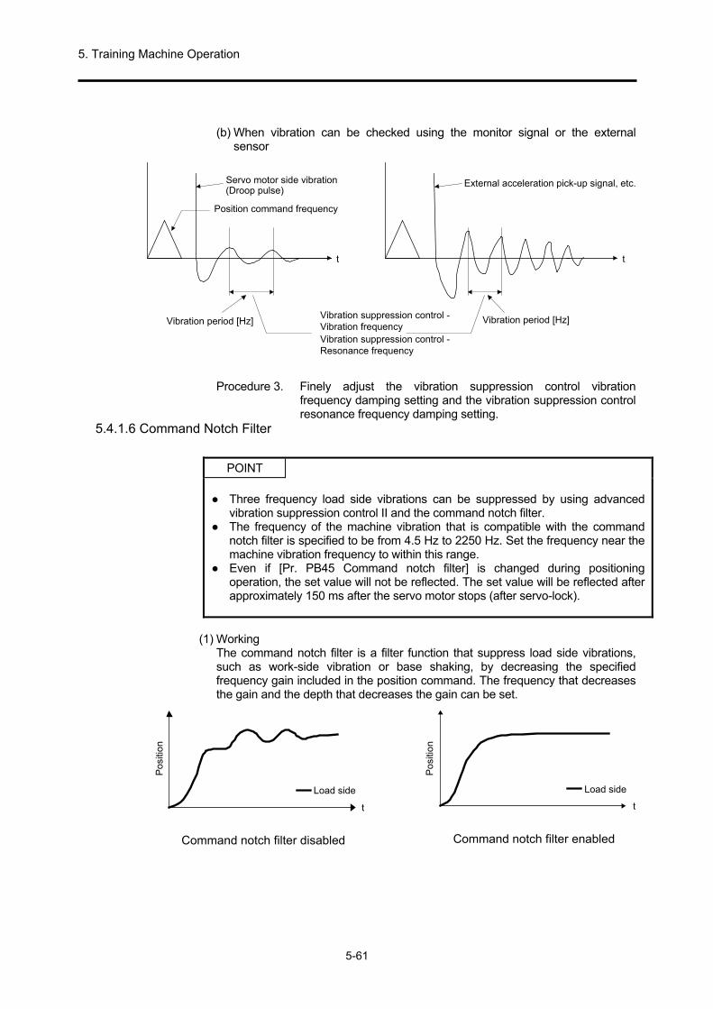
5. Training Machine Operation
5-61
(b) When vibration can be checked using the monitor signal or the external
sensor
t
Servo motor side vibration(Pulse droop)
t
External acceleration pick-up signal, etc.
Vibration suppression control -Vibration frequencyVibration suppression control -Resonance frequency
Vibration period [Hz] Vibration period [Hz]
Position command frequency
Procedure 3. Finely adjust the vibration suppression control vibration frequency damping setting and the vibration suppression control resonance frequency damping setting.
5.4.1.6 Command Notch Filter
POINT
Three frequency load side vibrations can be suppressed by using advanced
vibration suppression control II and the command notch filter. The frequency of the machine vibration that is compatible with the command
notch filter is specified to be from 4.5 Hz to 2250 Hz. Set the frequency near the machine vibration frequency to within this range.
Even if [Pr. PB45 Command notch filter] is changed during positioning operation, the set value will not be reflected. The set value will be reflected after approximately 150 ms after the servo motor stops (after servo-lock).
(1) Working The command notch filter is a filter function that suppress load side vibrations, such as work-side vibration or base shaking, by decreasing the specified frequency gain included in the position command. The frequency that decreases the gain and the depth that decreases the gain can be set.
Load side
t
Command notch filter disabled
Load side
t
Command notch filter enabled
Pos
ition
Pos
ition
(Droop pulse)

5. Training Machine Operation
5-62
(2) Parameter Set [Pr. PB45 Command notch filter] as follows. Set the command notch filter setting frequency to a value near the vibration frequency on the load side.
Set value
Command notch filter setting frequency
Set value Frequency[Hz]
Frequency[Hz] Set value Frequency
[Hz]
00
01
02
03
0
04
05
06
07
08
09
0A
0B
0C
0D
0E
0F
10
11
12
13
14
15
1617
18
19
1A
1B1C
1D
1E
1F
20
21
22
23
24
25
26
27
28
29
2A
2B
2C
2D
2E
2F
30
31
32
33
34
35
3637
38
39
3A
3B3C
3D
3E
3F
40
41
42
43
44
45
46
47
4849
4A
4B
4C
4D
4E
4F
50
51
52
53
54
55
56
57
58
59
5A
5B
5C
5D
5E
5F
Disabled
2250
1125
750
562
450
375
321
281
250
225
204
187
173
160
150
140
132
125
118
112
107
102
97
93
90
86
83
80
77
75
72
70
66
62
59
56
53
51
48
46
45
43
41
40
38
37
36
35.2
33.1
31.3
29.6
28.1
26.8
25.6
24.5
23.4
22.5
21.6
20.8
20.1
19.4
18.8
18.2
17.6
16.5
15.6
14.8
14.1
13.4
12.8
12.2
11.7
11.3
10.8
10.4
10.0
9.7
9.4
9.1
8.8
8.3
7.8
7.4
7.0
6.7
6.4
6.1
5.9
5.6
5.4
5.2
5.0
4.9
4.7
4.5
Notch depth
0
1
2
3
4
5
6
7
8
9
A
B
CD
E
F
Set value Depth [dB]
[Pr.PB45]
-40.0
-24.1
-18.1
-14.5
-12.0
-10.1
-8.5
-7.2
-6.0
-5.0
-4.1
-3.3
-2.5
-1.8
-1.2-0.6

5. Training Machine Operation
5-63
5.4.2 Gain Switching Function
With this function, the gain can be switched. Gain can be switched during rotation and when stopped, and also when using the input device during the operation. 5.4.2.1 Application
This function is used in the following cases.
(1) Although the gain during servo-lock is to be increased, the gain during rotation is to be decreased so that the driving sound is suppressed.
(2) When gain is to be decreased during the settling time in order to shorten the stop
settling time. (3) When gain is to be switched by the input device so that servo system stability is
maintained to counteract wide fluctuations of load to motor inertia ratio when stopped (when a heavy transport material is packed on the cart).

5. Training Machine Operation
5-64
5.4.2.2 Function Block Diagram Each control gain, load to motor inertia ratio, and vibration suppression control can be switched based on the conditions selected from [Pr. PB26 Gain switching function] and [Pr. PB27 Gain switching condition].
Command pulsefrequency
+-
Pulse droop
Model speed
Input device (CDP)
Comparator
Switching
CDP[Pr.PB26]
+-
+-
GD2[Pr.PB06]
GD2B[Pr.PB29]
Valid GD2value
Valid VRF12value
Valid VRF11value
Valid VRF13value
Valid VRF14value
Valid VRF21value
Valid VRF22value
Valid VRF23value
Valid VRF24value
Valid PG1value
Valid PG2value
Valid VG2value
Valid VICvalue
PG1[Pr.PB07]
PG1B[Pr.PB60]
PG2[Pr.PB08]
PG2B[Pr.PB30]
VG2[Pr.PB09]
VG2B[Pr.PB31]
VIC[Pr.PB10]
VICB[Pr.PB32]
VRF11[Pr.PB19]
VRF11B[Pr.PB33]
VRF12[Pr.PB20]
VRF12B[Pr.PB34]
CDL[Pr.PB27]
VRF13[Pr.PB21]
VRF13B[Pr.PB35]
VRF14[Pr.PB22]
VRF14B[Pr.PB36]
VRF21[Pr.PB52]
VRF21B[Pr.PB56]
VRF22[Pr.PB53]
VRF22B[Pr.PB57]
VRF23[Pr.PB54]
VRF23B[Pr.PB58]
VRF24[Pr.PB55]
VRF24B[Pr.PB59]
Droop pulse

5. Training Machine Operation
5-65
5.4.2.3 Parameter When using the gain switching function, make sure to select "Manual mode (_ _ _ 3)" in "Gain adjustment mode selection" of [Pr. PA08 Auto tuning mode]. The gain switching function cannot be used in the auto tuning mode.
(1) Variable gain operation setting parameter
Parameter
number Abbreviation Name Unit Description
PB26 CDP Gain switching selection
Select the switching condition.
PB27 CDL Gain switching condition
[kpps] /[pulse] /[r/min]
Set the value of the switching conditions.
PB28 CDT Gain switching time constant
[ms] The filter time constant can be set with regard to the gain changes while switching.
(a) [Pr. PB26 Gain switching function]
Set the gain switching conditions. Select the switching conditions in the first and second digits.
Gain switching selection0: Disabled1: Input device (CDP (gain switching))2: Command frequency3: Pulse droop4: Servo motor speed
0
Gain switching condition0: Gain enabled after switching above the switching condition1: Gain enabled after switching under the switching condition
[Pr.PB26]
0
(b) [Pr. PB27 Gain switching condition] Set the level for switching the gain when "Command frequency", "Droop pulse", or "Servo motor speed" is selected in [Pr. PB26 Gain switching function]. The setting unit is as follows.
Gain switching condition Unit
Command frequency [kpps] Droop pulse [pulse]
Servo motor speed [r/min]
(c) [Pr. PB28 Gain switching time constant]
The first-order delay filter can be set for each gain at the time of gain switching. Use to reduce the impact on the machine when the gain difference is not excessive when gain switching.
Droop pulse

5. Training Machine Operation
5-66
(2) Changeable gain parameter
Control gain Before switching After switching
Parameter Abbreviation Name Parameter Abbreviation Name Load to motor inertia ratio PB06 GD2
Load to motor inertia ratio
PB29 GD2B Gain switching Load to motor inertia ratio
Model loop gain PB07 PG1 Model loop gain PB60 PG1B
Gain switching Model loop gain
Position loop gain PB08 PG2 Position loop gain PB30 PG2B
Gain switching Position loop gain
Speed loop gain PB09 VG2 Speed loop gain PB31 VG2B
Gain switching Speed loop gain
Speed integral compensation
PB10 VIC Speed integral compensation
PB32 VICB Gain switching Speed integral compensation
Vibration suppression control 1 Vibration frequency
PB19 VRF11 Vibration suppression control 1 Vibration frequency
PB33 VRF11B Vibration suppression control 1 after gain switching Vibration frequency
Vibration suppression control 1 Resonance frequency
PB20 VRF12 Vibration suppression control 1 Resonance frequency
PB34 VRF12B Vibration suppression control 1 after gain switching Resonance frequency
Vibration suppression control 1 Vibration frequency damping
PB21 VRF13
Vibration suppression control 1 Vibration frequency damping
PB35 VRF13B Vibration suppression control 1 after gain switching Vibration frequency damping
Vibration suppression control 1 Resonance frequency damping
PB22 VRF14
Vibration suppression control 1 Resonance frequency damping
PB36 VRF14B Vibration suppression control 1 after gain switching Resonance frequency damping
Vibration suppression control 2 Vibration frequency
PB52 VRF21 Vibration suppression control 2 Vibration frequency
PB56 VRF21B Vibration suppression control 2 after gain switching Vibration frequency
Vibration suppression control 2 Resonance frequency
PB53 VRF22 Vibration suppression control 2 Resonance frequency
PB57 VRF22B Vibration suppression control 2 after gain switching Resonance frequency
Vibration suppression control 2 Vibration frequency damping
PB54 VRF23
Vibration suppression control 2 Vibration frequency damping
PB58 VRF23B Vibration suppression control 2 after gain switching Vibration frequency damping
Vibration suppression control 2 Resonance frequency damping
PB55 VRF24
Vibration suppression control 2 Resonance frequency damping
PB59 VRF24B Vibration suppression control 2 after gain switching Resonance frequency damping
(a) [Pr. PB06] to [Pr. PB10]
These parameters are normally the same as manual adjustment. If gain switching is performed, the values of load to motor inertia ratio, position loop gain, speed loop gain, and speed integral compensation can be changed.
(b) [Pr. PB19] to [Pr. PB22]/[Pr. PB52] to [Pr. PB55] These parameters are normally the same as manual adjustment. If gain switching is performed when the servo motor is stopped, the vibration frequency, resonance frequency, vibration frequency damping settings, and resonance frequency damping settings can be changed.
(c) [Pr. PB29 Load to motor inertia ratio after gain switching] Set the load to motor inertia ratio after switching. When the load to motor inertia ratio is not changed, set it to the same value as the [Pr. PB06 load to motor inertia ratio] value.
(d) [Pr. PB30 Position loop gain after gain switching]/[Pr. PB31 Speed loop gain after gain switching]/[Pr. PB32 Speed integral compensation after gain switching] Set the position loop gain, speed loop gain, and speed integral compensation after gain switching.
(e) Vibration suppression control after gain switching ([Pr. PB33] to [Pr. PB36]/[Pr. PB56]/[Pr. PB59]/[Pr. PB60 Model loop gain after gain switching]) Gain switching vibration suppression control and model loop gain can only be used by turning the input device (CDP) on/off. The vibration frequency, resonance frequency, vibration frequency damping settings, and resonance frequency damping settings of vibration suppression control 1 and vibration suppression control 2 can be changed.

5. Training Machine Operation
5-67
5.4.2.4 Gain Switching Procedure
This section explains by giving an example of the settings.
(1) If switching by the input device (CDP) is selected
(a) Settings Parameter Abbreviation Name Setting value Unit
PB06 GD2 Load to motor inertia ratio 4.00 [times] PB07 PG1 Model loop gain 100 [rad/s] PB08 PG2 Position loop gain 120 [rad/s] PB09 VG2 Speed loop gain 3000 [rad/s] PB10 VIC Speed integral compensation 20 [ms] PB19 VRF11 Vibration suppression control 1 - Vibration frequency 50 [Hz] PB20 VRF12 Vibration suppression control 1 - Resonance frequency 50 [Hz]
PB21 VRF13 Vibration suppression control 1 - Vibration frequency damping
0.20
PB22 VRF14 Vibration suppression control 1 - Resonance frequency damping
0.20
PB52 VRF21 Vibration suppression control 2 - Vibration frequency 20 [Hz] PB53 VRF22 Vibration suppression control 2 - Resonance frequency 20 [Hz]
PB54 VRF23 Vibration suppression control 2 - Vibration frequency damping
0.10
PB55 VRF24 Vibration suppression control 2 - Resonance frequency damping
0.10
PB29 GD2B Load to motor inertia ratio after gain switching 10.00 [times] PB60 PG1B Model loop gain after gain switching 50 [rad/s] PB30 PG2B Position loop gain after gain switching 84 [rad/s] PB31 VG2B Speed loop gain after gain switching 4000 [rad/s] PB32 VICB Speed integral compensation after gain switching 50 [ms]
PB26 CDP Gain switching function 0001
(Switch the input device (CDP) on/off.)
PB28 CDT Gain switching time constant 100 [ms]
PB33 VRF11B Vibration suppression control 1 - Vibration frequency after gain switching
60 [Hz]
PB34 VRF12B Vibration suppression control 1 - Resonance frequency after gain switching
60 [Hz]
PB35 VRF13B Vibration suppression control 1 - Vibration frequency damping after gain switching
0.15
PB36 VRF14B Vibration suppression control 1 - Resonance frequency damping after gain switching
0.15
PB56 VRF21B Vibration suppression control 2 - Vibration frequency after gain switching
30 [Hz]
PB57 VRF22B Vibration suppression control 2 - Resonance frequency after gain switching
30 [Hz]
PB58 VRF23B Vibration suppression control 2 - Vibration frequency damping after gain switching
0.05
PB59 VRF24B Vibration suppression control 2 - Resonance frequency damping after gain switching
0.05

5. Training Machine Operation
5-68
(b) Timing chart when switching
Gain after switching
63.4%
CDT = 100ms
Gain before switchingChange in each gain
CDP (gain switching) OFF ON OFF
Model loop gain 100 → 50 → 100 Load to motor inertia ratio 4.00 → 10.00 → 4.00 Position loop gain 120 → 84 → 120 Speed loop gain 3000 → 4000 → 3000 Speed integral compensation 20 → 50 → 20 Vibration suppression control 1 - Vibration frequency
50 → 60 → 50
Vibration suppression control 1 - Resonance frequency
50 → 60 → 50
Vibration suppression control 1 - Vibration frequency damping
0.20 → 0.15 → 0.20
Vibration suppression control 1 - Resonance frequency damping
0.20 → 0.15 → 0.20
Vibration suppression control 2 - Vibration frequency
20 → 30 → 20
Vibration suppression control 2 - Resonance frequency
20 → 30 → 20
Vibration suppression control 2 - Vibration frequency damping
0.10 → 0.05 → 0.10
Vibration suppression control 2 - Resonance frequency damping
0.10 → 0.05 → 0.10
(2) When switching is done using droop pulse
In this case, vibration suppression control after gain switching and model loop gain after gain switching cannot be used.
(a) Settings
Parameter Abbre- viation
Name Setting value Unit
PB06 GD2 Load to motor inertia ratio 4.00 [times] PB08 PG2 Position loop gain 120 [rad/s] PB09 VG2 Speed loop gain 3000 [rad/s] PB10 VIC Speed integral compensation 20 [ms]
PB29 GD2B Load to motor inertia ratio after gain switching
10.00 [times]
PB30 PG2B Position loop gain after gain switching 84 [rad/s] PB31 VG2B Speed loop gain after gain switching 4000 [rad/s]
PB32 VICB Speed integral compensation after gain switching
50 [ms]
PB26 CDP Gain switching function 0003
(Switch using droop pulse.)
PB27 CDL Gain switching condition 50 [pulse] PB28 CDT Gain switching time constant 100 [ms]

5. Training Machine Operation
5-69
(b) Timing chart when switching
Gain after switching
63.4%
CDT = 100ms
Gain before switchingChange in each gain
Pulse droop [pulse]+CDL
- CDL0
Command pulse Pulse droop
Load to motor inertia ratio 4.00 → 10.00 → 4.00 → 10.00 Position loop gain 120 → 84 → 120 → 84 Speed loop gain 3000 → 4000 → 3000 → 4000 Speed integral compensation 20 → 50 → 20 → 50
Droop pulse
Droop pulse

5. Training Machine Operation
5-70
5.4.3 Tough Drive Function
POINT
Set whether to enable/disable the tough drive function using [Pr. PA20 Tough
drive setting].
Tough drive function is a function that continues operation so that the device does not stop even when there is an alarm.
5.4.3.1 Vibration Tough Drive Function
The vibration tough drive function is a function that instantly resets the filter and prevents vibration when the machine resonance vibration frequency fluctuates and when machine resonance occurs due to changes in the machine over the years. In order to reset the machine resonance suppression filter with the vibration tough drive function, it is important that [Pr. PB13 Machine resonance suppression filter 1] and [Pr. PB15 Machine resonance suppression filter 2] are set in advance. Set [Pr. PB13] and [Pr. PB15] using the following method.
(1) Implementation of one-touch tuning (refer to section 5.3.2) (2) Manual setting (refer to section 5.3.4)
Operate the vibration tough drive function if the retrieved resonance frequency is within ±30% of the range with regard to the set value of [Pr. PB13 Machine resonance suppression filter 1] and [Pr. PB15 Machine resonance suppression filter 2]. The sensitivity can be set for the detection level of the vibration tough drive function using [Pr. PF23 Vibration tough drive - Oscillation detection level].
POINT
The resetting of [Pr. PB13] and [Pr. PB15] is always executed by the vibration
tough drive function; however, the number of writes to EEP-ROM in 1 hour is 1. [Pr. PB46 Machine resonance suppression filter 3], [Pr. PB48 Machine
resonance suppression filter 4], and [Pr. PB50 Machine resonance suppression filter 5] are not reset by the vibration tough drive function.
Vibrations less than 100 Hz cannot be detected by the vibration tough drive function.

5. Training Machine Operation
5-71
The following figure shows the function block diagram of the vibration tough drive function. Compare the detected machine resonance frequency with [Pr. PB13 Machine resonance suppression filter 1] and [Pr. PB15 Machine resonance suppression filter 2], and reset the machine resonance frequency considering the closest set value.
Filter Set parameter Precautions
Parameters to be reset using the
vibration tough drive function
Machine resonance suppression filter 1
PB01/PB13/PB14 Automatic adjustment is possible using "Filter tuning mode selection" of [Pr. PB01].
PB13
Machine resonance suppression filter 2
PB15/PB16 PB15
Machine resonance suppression filter 3
PB46/PB47
Machine resonance suppression filter 4
PB48/PB49 If this filter is enabled, the shaft resonance suppression filter cannot be used. The shaft resonance suppression filter is enabled in the initial setting.
Machine resonance suppression filter 5
PB50/PB51 Even if it is set, this filter is disabled when the robust filter is being used. The robust filter is disabled in the initial setting.
Commandpulse train
Commandfilter
Machineresonance
suppressionfilter 1
Machineresonance
suppressionfilter 4
Machineresonance
suppressionfilter 5
Machineresonance
suppressionfilter 2
Machineresonance
suppressionfilter 3
Parameters reset by thevibration tough drive function
Encoder
Servo motor
PWM M
Load
[Pr.PB13] [Pr.PB15] [Pr.PB46]
+-
Shaft resonancesuppression filter Robust filter
[Pr.PB48] [Pr.PB50]
[Pr.PB17]
[Pr.PB49] [Pr.PE41]
Torque
ALM(Malfunction)
WNG(Warning)
MTTR(During tough drive)
ON
OFF
[Pr. PF23 Vibration tough drive - Oscillation detection level]
The machine resonance is detected and the filter is automatically reset.
ON is not allowed by the vibration tough drive function.
ON
OFF
ON
OFF
5s
Update the parameter ofthe setting closest to themachine resonancefrequency.

5. Training Machine Operation
5-72
5.4.3.2 Instantaneous Power Failure Tough Drive
CAUTION
During the instantaneous power failure tough drive, the torque can be restricted depending on the set value of [Pr. PF25 Instantaneous power failure tough drive - Detection time] or the load status.
The momentary power failure tolerance increases due to the instantaneous tough drive function. However, it does not comply with the SEMI-F47 standard.
The instantaneous tough drive function is a function that avoids [AL. 10 Undervoltage] even if instantaneous power failure occurs during operation. When instantaneous power failure tough drive is activated, the momentary power failure tolerance can be increased and, at the same time, the "AL. 10 Undervoltage" alarm level can be changed using the electrical energy charged in the capacitor in the servo amplifier during instantaneous power failure. The [AL. 10.1 Voltage drop in the control circuit power] detection period for the control circuit power supply can be changed in [Pr. PF25 Instantaneous power failure tough drive - Detection time]. Also, the [AL. 10.2 Voltage drop in the main circuit power] detection level for bus voltage is set automatically.
POINT
MBR (Electromagnetic brake interlock) cannot be turned off during instantaneous power failure tough drive.
Regardless of the set value of [Pr. PF25 Instantaneous power failure tough drive - Detection time], if the load at the time of momentary power failure is large, there may be an undervoltage alarm ([AL. 10.2]) due to a drop in bus voltage.
(1) When control circuit power supply momentary power failure period > [Pr. PF25 Instantaneous power failure tough drive - Detection time] When the control circuit power supply momentary power failure period exceeds [Pr. PF25 Instantaneous power failure tough drive - Detection time], an alarm occurs. MTTR (during tough drive) is turned on after a momentary power failure is detected. MBR (electromagnetic brake interlock) is turned off when an alarm occurs.
Control circuitpower supply
Bus voltage
Undervoltage level(158 V DC)
ALM(Malfunction)
WNG(Warning)
MTTR(During tough drive)
MBR(Electromagneticbrake interlock)
Base circuit
Control circuit power supplymomentary power failure time

5. Training Machine Operation
5-73
(2) When control circuit power supply momentary power failure period < [Pr. PF25 Instantaneous power failure tough drive - Detection time] Depending on the bus voltage drop status, the operation condition will differ.
(a) When the bus voltage drops below 158 V DC during the control circuit power
supply momentary power failure period [AL. 10 Undervoltage] occurs when the bus voltage drops below 158 V DC even if instantaneous power failure tough drive is enabled.
[Pr.PF25]
ON
OFF
ON
OFF
ON
OFF
ON
OFF
ON
OFF
ON
OFF
Control circuitpower supply
Bus voltage
Undervoltage level(158 V DC)
ALM(Malfunction)
WNG(Warning)
MTTR(During tough drive)
MBR(Electromagneticbrake interlock)
Base circuit
Control circuit power supplymomentary power failure time
(b) When the bus voltage does not drop below 158 V DC during the control circuit power supply momentary power failure period No alarm occurs and operation continues as is.
[Pr.PF25]
ON
OFF
ON
OFF
ON
OFF
ON
OFF
ON
OFF
ON
OFF
Control circuitpower supply
Bus voltage
Undervoltage level(158 V DC)
ALM(Malfunction)
WNG(Warning)
MTTR(During tough drive)
MBR(Electromagneticbrake interlock)
Base circuit
Control circuit power supplymomentary power failure time

5. Training Machine Operation
5-74
5.4.4 Connection of Laboratory Device
MR-J4-10A
AC100V
F(5A)
QD75D1N
Servo amplifier
24 V DCpower supply
Main circuitpower supply
Positioning module
Signal name Pinnumber
Signalname
Pinnumber
Forward run pulse train
Reverse run pulse train
Ready
Detector phase Z pulse
Clear
Shield
Digital I/F power supply input
Digital I/F common
Control common
Emergency stop
Servo-on
Reset
Speed selection 1
Speed selection 2
Forward rotation start
Reverse rotation start
Torque limit selection
Digital I/F common
Digital I/F power supply input
Malfunction
Zero speed detection
Limiting torque
Positioning completed/speed reached
Ready
15 V DC power output
Analog speed command
Control common
Analog torque limit
Shield
Differential drivercommon terminal
Input module
Manual/auto switchingswitch
Start button
Stop button
Home position return button
Continuous operation/one-cycleoperation switch
Servo alarm
Reverse rotation JOGbutton
Forward rotation JOGbutton
Home position dog(DOG)
Plate
Plate
Step-up transformer100 V AC→230 VAC
Torque limitselection

5. Training Machine Operation
5-75
MR-J4-10A
HG-KR053
MR-PWS1CBL2M-A2-L
MR-J3ENCBL2M-A2-L
MR-J3USBCBL3M
Servo amplifier
Servo motor
Servo motorpower cable Timing belt
mechanism
Powderbrake
300 mA total
Encoder cable
+1 mA totalSignalname
Pinnumber
Communication cable(Optional)
Load factor
Load set value
Monitor 1

5. Training Machine Operation
5-76
Memo

6. Selection
6-1
6.1 Temporary Selection of Motor Capacity
The aim of the guidelines for selecting the AC servo capacity for the drive axis structure is as follows. (1) Aim of control loop stability
Load moment of inertia JL ≤ Motor rotor moment of inertia JM × Suggested load moment of inertia (2) Load torque allowance
Load torque TL ≤ Motor rated torque TM × 0.5 to 0.8 6.1.1 Load Moment of Inertia JL This is the moment of inertia of the drive system after the span ring structure and coupling linked with the motor output shaft that form the motor load. The electromagnetic brake and motor reduceris also included. Also, in the AC servo system, the unit used for the load moment of inertia JLis [kgcm2], and the calculation formula of the load moment of inertia is given in Table 6.1. 6.1.2 Load Torque TL
This is said to be the thrust, frictional force, and the unbalanced torque, which act on the machine moving parts that form the motor load. Also, the unit used for the load torque TL is [Nm], and the calculation formula of the load torque is given in Table 6.2. Remarks: Various calculation formula symbols are used as per Appendix 1.

6. Selection
6-2
6.1.3 Load Moment of Inertia/Load Torque Calculation Formula (1) Load moment of inertia calculation formula
The typical calculation formula for the moment of inertia is given in Table 6.1.
Table 6.1 Calculation formula of load moment of inertia
Type Mechanism Calculation formula
1. Cylinder Axis of rotation
·················· (6-1)
JL: Load moment of inertia [kgcm2] ρ: Density of cylinder material [kg/cm3] L: Length of cylinder [cm] D1: Outside diameter of cylinder [cm] D2: Inside diameter of cylinder [cm] W: Weight of the cylinder [kg]
Reference data: Material density – Iron: 7.8/10-3[kg/cm3] Aluminum: 2.7/10-3 [kg/cm3] Copper: 8.96/10-3 [kg/cm3]
2. Rectangular prism
Axis of rotation
········································· (6-2)
a, b, R: Left figure [cm]
3. Object that moves linearly Motor
························································ (6-3)
JL: Load moment of inertia at motor shaft [kg/cm2] V: Speed of object moving linearly [mm/min] N: Motor rotation speed [r/min]
Z1, Z2: Number of gear teeth
4. Object to be suspended
················································ (6-4)
JP: Pulley moment of inertia [kgcm2] D: Pulley diameter [cm]
5. Motor shaft conversion load moment of inertia
Load B
Load A
Motor
··························· (6-5)
JA, JB: Load A, Moment of inertia B [kgcm2] J11to J31: Moment of inertia of gear [kgcm2] N1to N3: Speed of each shaft [r/min]

6. Selection
6-3
(2) Load torque calculation formula
The typical calculation formula for the load torque is given in Table 6.2.
Table 6.2 Load torque calculation formula
Type Mechanism Calculation formula
Linear movement
Load B
Load A
Motor
····················· (6-6)
F: Strength of linearly moving machine in axial direction (thrust) [N] η: Efficiency of the drive system
For example, when moving the table as in the figure to the left, the force F is obtained as follows:
F = Fc + μ (Wg + FG) ········································· (6-7)
Fc: Force applied in the axial direction of the moving part (thrust) [N] FG: Tightening force of the table guide surface [N] µ: Friction coefficient V: Speed of object moving linearly [mm/min] N: Motor rotation speed [r/min] W: Object mass [kg] g: Gravitational acceleration [ 9.8 m/s2 ] ∆S: Feed length of moving object in 1 rotation of the motor [mm]
Rotary movement
Motor
······································· (6-8)
TLO: Load torque on the load shaft [Nm] TL: Friction load torque of motor shaft conversion [Nm] TF: Friction torque of the moving part [Nm]
Vertical movement
Counterweight
Load
When rising TL = TU + TF ··················································· (6-9)
When descending TL = - η2TU + TF ·············································· (6-10)
TU: Unbalanced torque [Nm] TF: Friction torque of the moving part [Nm]
······· (6-11)
································ (6-12)
W1: Weight of load [kg] W2: Mass of counterweight [kg] η: Drive system efficiency µ: Friction coefficient (sieve)

6. Selection
6-4
6.2 Reduction Ratio In order to sufficiently exert the servo motor capacity, it is important to efficiently pull the servo motor power and to use the servo system that includes the machine by increasing its stability and response. For this, the major element is the reduction ratio, which is introduced between the servo motor and the machine. The conditions for selecting the reduction ratio correctly are explained below. (1) To use the maximum motor output (power), select so that the motor is operated at the rated speed when the
machine is at its fastest. 1) The servo motor gives the maximum output (rated output) at the rated speed. 2) The load torque at motor shaft and load moment of inertia at motor shaft of the machine decreases when the
reduction ratio increases. In other words, when the reduction ratio is selected so as to operate at the rated speed, the observed load from the motor will become lighter.
(2) In order to stably increase the response of the servo system, select the reduction ratio and motor capacity so that
the load to motor inertia ratio is less than a factor of the recommended load to motor inertia ratio (less than 30 times for HC-MFS motor).
Motor shaft conversion load JL Load to motor inertia ratio m = < Recommended load to motor inertia ratio
Motor JM
The response can be increased by decreasing the load to motor inertia ratio. Therefore, select so that it is as small (m<2) as possible at the time of high-frequency transmission.
(3) To ensure positioning accuracy, it is preferred that the feed length for 1 pulse ∆0 is small.
The following is usually a guide for the relationship between machine accuracies ∆ε and ∆0.
∆0 < to 51
101 )( × ∆
Note: Refer to section 2.5.1 for the relationship between ∆0 and the reduction ratio.
<Reference> 1. The power during acceleration time is smallest when m = 1 is set. In other words, set to the following:
1 / n = J / JM L This reduction ratio is generally referred to as the optimum reduction ratio. 2. In case of accelerating using the spur gear or pulley, take care as the load moment of inertia increases conversely due to
deceleration if the pulley diameter on the machine side is increased in order to increase the reduction ratio.

6. Selection
6-5
6.3 Operation Pattern and Motor Required Torque The operation pattern is generally divided into acceleration time Tpsa, constant-speed operation tc, acceleration time Tpsd, stop settling time ts, and stop time tst, and then considered. The energy required while accelerating the object having moment of inertia (load moment of inertia JL) is called acceleration torque Ta, and similarly it is called deceleration torque Td while decelerating. Also, in the stop settling time after decelerating from the constant-speed operation, the friction load torque TL is operated similar to that during the constant-speed operation.
6.3.1 Acceleration Torque Ta The calculation formula for acceleration torque Ta is the expression (6-13):
(JL+JM)No - Ta = (1-ε ) [Nm] ······················································· (6-13)
9.55×10⁴Tpsa
Use the simplified calculation formula (6-14).
(JL+JM)No Ta = [Nm] ······································································· (6-14)
9.55×10⁴Tpsa
6.3.2 Deceleration Torque Td The calculation formula of deceleration torque Td is the same as (6-15):
(JL+JM)No - Td = ・(1-ε ) [Nm] ······················································· (6-15)
9.55×10⁴Tpsa
Use the simplified calculation formula (6-16).
(JL+JM)No Td = [Nm] ······································································· (6-16)
9.55×10⁴Tpsa
Also, when Tpsa = Tpsd, the acceleration torque and the deceleration torque have the same value Ta = -(Td).
Tpsa Tp
Tpsa Tp

6. Selection
6-6
6.3.3 Operation Pattern If the items describe up to here are organized as an operation pattern, the following will apply. (1) The motor torque required during a constant speed is the load torque at motor shaft TL. (2) Increasing/decreasing the load torque at motor shaft TL is positive/negative depending on the conditions. (3) The motor torque required during acceleration/deceleration is as follows.
Motor torque during acceleration TMa = Load torque TL+ Acceleration torque Ta Motor torque during deceleration TMd = Load torque TL- Deceleration torque Td
(4) The motor decelerates by supplying energy to the machine at power drive deceleration when TMd = TL - Td > 0.
(5) The motor is decelerated by applying brakes to the machine when there is regenerative braking (regenerative mode) when TMd = TL – Td < 0. The regenerative power flow is from the machine side to the amplifier side.
(6) If the deceleration pattern and the torque pattern are arranged, the result will look like Figure 6.1.
Figure 6.1 Operation pattern and individual section torque pattern
Pu
lse
freq
uen
cy
Mot
or
rota
tion
spe
ed
Loa
dto
rqu
eA
ccel
erat
ion/
dece
lera
tion
torq
ue
(a)
Acc
eler
atio
n/
dece
lera
tion
torq
ue(b
)N
eces
sary
mo
tor
torq
ue
Input pulse frequency
Motor rotation speed
(Remarks)
Due to a control system delay,the acceleration anddeceleration torque is as shownin Figure (a). However, forsimplification of the calculations,the torque is calculated with Taand Tb of Figure (b).
One operation cycle
Power runningmode
Regenerativedriving mode
tC tC
t0
tf
tst stop time [s]
tf 1 operation torque [s]
[s]
[s]
[s]
t[s]
[s]

6. Selection
6-7
6.3.4 Determining Motor Capacity The availability of the motor is first determined by whether it can cover the necessary motor torque in Figure 6.1. However, in addition to this, it is necessary to examine the rise in motor temperature and the regenerative brake heat capacity for repetitive usage. A temporary selected motor can be used if it fulfills the following three conditions. (1) Motor torque TMa required during acceleration in Figure 6.1
TMa = TL+Ta < Motor maximum torque TMmax ··········································································· (6-17) (2) Motor torque TMd required during deceleration in figure 6.1
TMd = TL-Td < Motor maximum torque TMmax ············································································ (6-18) (3) Continuous effective load torque Trms
Trms ≤ Motor rated torque TM ········································································································· (6-19) The continuous effective load torque Trms represents the load torque that is equivalent to when there is a continuous temperature rise in a motor that operates in an intermittent cycle. Therefore, if Trms ≤ TM, there is no temperature issue. Trms in Figure 6.1 is obtained using the following formula.
T Tpsa + T (t0 - Tpsa - Tpsd - Ts) + T Tpsd Trms = [Nm] ············· (6-20)
tf If any of the above conditions ((1), (2) or (3)) are not fulfilled, revise the machine side conditions, the operation pattern, and the motor capacity, and reexamine using a similar procedure. If all of the above conditions ((1), (2) and (3)) are fulfilled, then there is no issue of torque or temperature rise even if the temporarily selected motor is operated using the speed pattern and cycle time according to plan. However, if negative torque occurs in the torque pattern, the efficiency of the regenerative brake of the servo amplifier also needs to be studied. Refer to the examination of regenerative brake option necessity in section 6.3.5.
(One operation cycle)
2 Ma
2 L
2Md

6. Selection
6-8
6.3.5 Capacity Selection Flow and Calculation
(1) Ball screw horizontal (1) Selection flow
Capacity selection start
Calculation of travel distanceper motor rotation
Calculation of motor rotationspeed
Load moment of inertiacalculation
Motor shaft calculationLoad torque calculation
Acceleration torque examination
Continuous effective loadtorque calculation
Examination of regenerativebrake option necessity
Deceleration torque examination
Capacity selection complete
Motor temporaryselection
Calculation of stop setting time
Acceleration possible
Deceleration possible
Continuous operationpossible
Apply regenerativebrake
Regenerative brakeselection
YES
YES
YES
YES
YESNO
NO
NO
NO
Calculation ofacceleration/deceleration time
Selection guideline Judgment Calculate the travel distance per motor rotation ∆S = PB x 1/n x 1/nm [mm/rev]
Calculate the motor rotation speed N0 = V0/∆S [r/min]
Calculate the stop settling time ts = 3 x 1/Kp [s]
Calculate the acceleration/deceleration time Tsa = Tsd = t0-(L/V0 x 60+ts) [s]
Calculate the load moment of inertia at motor shaft JB = (π x 0.0078 x (LB/10))/32 x (DB/10)4 [kgcm2] JF = (WT+WL) x (∆S / 20π)2 [kgcm2] JL = JMG+JMB+JF+JG+JC+J0+JB x (1/n)2 x (1/nm)2 [kgcm2]
Calculate the load torque at motor shaft TL = (Fc+ μ x (WT+WL) x g+FG) x ∆S /(2000 x π x η) [Nm]
The rated torque of the motor is more than the load torque at motor shaft The moment of inertia is less than the recommended load to motor inertia ratio (catalog value) The Motor rated speed is more than the motor rotation speed at the time of positioning The electrical accuracy is within the request specifications ∆L=(∆S / Pf) x 1000 [µm/pulse]
(0.5 to 0.8)/ Ttyp > TL m = JL/JM < catalog value NR > NO ∆L < request specifications
Calculate the acceleration torque (motor required torque required during acceleration time) TMa = ((JL+JM) x N0)/(9.55 x 10000 x Tsa)+TL [Nm] Check whether the motor maximum torque is greater than the acceleration torque
Tmax > TMa
Calculate the deceleration torque (motor required torque required during deceleration time) TMd = ((JL+JM) x N0)/(9.55 x 10000 x Tsa)+TL [Nm] Check whether the motor maximum torque is greater than the deceleration torque Peak load ratio is within 300% Rp = (Maximum value |TMa|,|TMd|)/Ttyp x 100
Tmax > TMd Rp < 300
Calculate the continuous effective load torque tc = t0-Tsa-Tsd-ts [s] Trms = (TMa2 x Tsa + TL2 x tc + TMd2 x Tsd) / tf [Nm] Check whether the fixed torque of motor is greater than the continuous execution load torque Effective load ratio is within 100% Rrms = (Trms/Ttyp) x 100
Ttyp > Trms Rrms < 100
Calculate the regenerative power Ea = 0. 1047 x NO/2 x TMa x Tsa [J] Ed = 0. 1047 x NO/2 x TMd x Tsd [J] Ef = 0. 1047 x NO x TL x tc [J] Check whether regenerative power has occurred Absolute value of total negative energy within Em = Ea, Ed, Ef Pr = ηm x Em-(Wa x t)-Ec/tf [W] Select the permissible regenerative brake option that is more than the regenerative power Regenerative load ratio is within 100% Ld = (Pr/Ptyp) x 100
Pr > 0 Regenerative option > Pr Ld < 100

6. Selection
6-9
(2) Various important symbols related to the load and operation
Term Symbol Unit
Mac
hine
-sid
e sp
ecifi
catio
ns
Table weight WT kg Load mass WL kg Load anti-drag force Fc N Tightening force of the table guide surface FG N Speed deceleration ratio 1/n Reducer moment of inertia JG kgcm2 Coupling moment of inertia JC kgcm2 Other output shaft conversion moments of inertia JO kgcm2 Ball screw lead PB mm Ball screw diameter DB mm Ball screw length LB mm Drive system efficiency η Friction coefficient µ Fast feed speed VO mm/min Positioning length L mm Positioning time tO s 1 cycle time tf s
Spe
cific
atio
ns u
sed
for
sear
chin
g
Travel distance per motor rotation ∆S mm/rev Motor rotation speed NO r/min Stop settling time ts s Acceleration time Tsa s Deceleration time Tsd s Moment of inertia of ball screw JB kgcm2 Moment of inertia of object moving linearly JF kgcm2 Load moment of inertia at motor shaft JL kgcm2 Load torque at motor shaft TL Nm Acceleration torque (motor required torque required during acceleration time)
TMa Nm
Deceleration torque (motor required torque required during deceleration time)
TMd Nm
Continuous effective load torque Trms Nm Regenerative power Pr W Energy at time of acceleration Ea J Energy at time of deceleration Ed J Energy at time of constant speed Ef J Absolute value of negative energy total Em J Maximum regenerative power Pmax W Interval energy at time of maximum regeneration Emax J Reduction ratio of motor with reducer 1/nm *1 Encoder resolution Pf *1 pulse/rev Position loop gain Kp 1/s Moment of inertia of reducer of motor with reducer JMG *1 kgcm2 Moment of inertia of brake of motor with brake JMB *1 kgcm2 Motor moment of inertia JM *1 kgcm2 Recommended load to motor inertia ratio m *1 Motor rated speed NR *1 r/min Gravitational acceleration g m/s2 Motor maximum torque Tmax *1 Nm Motor rated torque Ttyp *1 Nm Motor inverse efficiency ηm *1 % Amplifier processing Wa *1 W Regenerative operation period t s Capacitor charging energy Ec *1 J Rated power of regeneration unit Ptyp *1 W Regenerative time during maximum regenerative driving tmax s
Note: (1) If there is a code max or min with the symbol (example: Tmax), then it represents a maximum value or a
minimum value, respectively. (2) If 1. 2. 3. n is attached to the symbol (example: I1, I2) then it represents an amount when respective
conditions differ in the amount represented by the symbol. *1. This numerical value is decided based on the combination of the temporarily selected capacity of the servo motor
and the servo amplifier. *2. The minimum required specifications for selecting the capacity is the coupling method in the load, the positioning
accuracy, and the shaded portion of the above table.

6. Selection
6-10
(2) Ball screw vertical (1) Selection flow
Capacity selection start
Calculation of travel distanceper motor rotation
Calculation of motor rotationspeed
Load moment of inertiacalculation
Motor shaft calculationLoad torque calculation
Continuous effective loadtorque calculation
Examination of regenerativebrake option necessity
Capacity selection complete
Motor temporaryselection
Calculation of stop setting time
Moving up possible
Moving down possible
Continuous operationpossible
Apply regenerativebrake
Regenerative brakeselection
YES
YES
YES
YES
YESNO
NO
NO
NO
Calculation ofacceleration/deceleration time
Examination of the acceleration/deceleration torque at the time
of moving up
Examination of the acceleration/deceleration torque at the time
of moving down
Selection guideline Judgment Calculate the travel distance per motor rotation ∆S = PB x 1/n x 1/nm [mm/rev]
Calculate the motor rotation speed N0 = V0/∆S [r/min]
Calculate the stop settling time ts = 3 x 1/Kp [s]
Calculate the acceleration/deceleration time Tsa = Tsd = t0-(L/V0 x 60+ts) [s]
Calculate the load moment of inertia at motor shaft JB = (π x 0.0078 x (LB/10))/32 x (DB/10)4 [kgcm2] JF = (WT+WL+WC) x (∆S / 20π)2 [kgcm2] JL = JMG+JMB+JF+JG+JC+J0+JB x (1/n)2 x (1/nm)2 [kgcm2]
Calculate the load torque at motor shaft TU = (Fc+ (WT+WL-WC) x g) x ∆S / 2000 x π [Nm] TF = μ x (WT+WL+WC) x g+FG) x ∆S / 2000 x π [Nm] TLu = (TU+TF) / η [Nm] (-TU+TF) > 0: TLd = (-TU+TF) / η [Nm] (-TU+TF) < 0: TLd = (-TU+TF) / η [Nm]
The rated torque of the motor is more than the load torque at motor shaft at the time of moving up The rated torque of the motor is more than the load torque at motor shaft at the time of moving down The moment of inertia is less than the recommended load to motor inertia ratio (catalog value) The Motor rated speed is more than the motor rotation speed at the time of positioning The electrical accuracy is within the request specifications ∆L=(∆S / Pf) x 1000 [µm/pulse]
(0.5 to 0.8)Ttyp > Tlu (0.5 to 0.8)Ttyp > Tld m = JL/JM < catalog value NR > NO ∆L < request specifications
Calculate the acceleration/deceleration torque at the time of moving up Acceleration: TMau = ((JL+JM) x N0)/(9.55 x 10000 x Tsa)+TLu [Nm] Deceleration: TMdu = -((JL+JM) x N0)/(9.55 x 10000 x Tsd)+TLu [Nm] Check whether the maximum torque of the motor is greater than the acceleration torque when moving up Check whether the maximum torque of the motor is greater than the acceleration torque when moving down
Tmax > TMau Tmax > TMdu
Calculate the acceleration/deceleration torque at the time of moving down Acceleration: TMad = ((JL+JM) x N0)/(9.55 x 10000 x Tsa)+TLd [Nm] Deceleration: TMdd = -((JL+JM) x N0)/(9.55 x 10000 x Tsd)+TLd [Nm] Check whether the maximum torque of the motor is greater than the deceleration torque when moving up Check whether the maximum torque of the motor is greater than the deceleration torque when moving down Peak load ratio is within 300% Rp = (Maximum value |TMa|,|TMd|)/Ttyp x 100
Tmax > TMad Tmax > TMdd Rp < 300
Calculate the continuous effective load torque tc = t0-Tsa-Tsd-ts [s]
Trms =(Tmau2 +Tmad2)×Tsa+(Tmdu2 +TMdd2)×Tsd + (Tlu2 + TLd2)×tc + TU2×(tf - 2 × t0+2×ts)
tf Check whether the fixed torque of the motor is greater than the continuous execution load torque Effective load ratio is within 100% Rrms = (Trms2/Ttyp) x 100
Ttyp > Trms Rrms < 100
Calculate the regenerative power Eau = 0.1047 x NO/2 x TMau x Tsa [J] Edu = 0.1047 x NO/2 x TMdu x Tsd [J] Efu = 0.1047 x NO x TLu x tc [J] Ead = 0.1047 x NO/2 x TMad x Tsa [J] Edd = 0.1047 x NO/2 x TMdd x Tsd [J] Efd = 0.1047 x NO x TLd x tc [J] Check whether regenerative power has occurred Absolute value of total negative energy within Em = Eau, Edu, Efu, Ead, Edd, Efd Pr = ηm x Em-(Wa x t)-Ec/tf [W] Select the permissible regenerative brake option that is more than the regenerative power Regenerative load ratio is within 100% Ld = (Pr/Ptyp) x 100
Pr > 0 Regenerative option > Pr Ld < 100

6. Selection
6-11
(2) Various important symbols related to the load and operation
Term Symbol Unit
Mac
hine
-sid
e sp
ecifi
catio
ns
Table weight WT kg Load mass WL kg Counterweight mass WC kg Load anti-drag force Fc N Tightening force of the table guide surface FG N Speed deceleration ratio 1/n Reducer moment of inertia JG kgcm2 Coupling moment of inertia JC kgcm2 Other output shaft conversion moments of inertia JO kgcm2 Ball screw lead PB mm Ball screw diameter DB mm Ball screw length LB mm Drive system efficiency η Friction coefficient µ Fast feed speed VO mm/min Positioning length L mm Positioning time tO s 1 cycle time tf s
Spe
cific
atio
ns u
sed
for
sear
chin
g
Travel distance per motor rotation ∆S mm/rev Motor rotation speed NO r/min Stop settling time ts s Acceleration time Tsa s Deceleration time Tsd s Moment of inertia of ball screw JB kgcm2 Moment of inertia of object moving linearly JF kgcm2 Load moment of inertia at motor shaft JL kgcm2 Load torque at motor shaft TL Nm Acceleration torque (motor required torque required duringacceleration time)
TMa Nm
Deceleration torque (motor required torque required duringdeceleration time)
TMd Nm
Continuous effective load torque Trms Nm Regenerative power Pr W Energy at time of acceleration Ea J Energy at time of deceleration Ed J Energy at time of constant speed Ef J Absolute value of negative energy total Em J Maximum regenerative power Pmax W Interval energy at time of maximum regeneration Emax J Reduction ratio of motor with reducer 1/nm *1 Encoder resolution Pf *1 pulse/rev Position loop gain Kp 1/s Moment of inertia of reducer of motor with reducer JMG *1 kgcm2 Moment of inertia of brake of motor with brake JMB *1 kgcm2 Motor moment of inertia JM *1 kgcm2 Recommended load to motor inertia ratio m *1 Motor rated speed NR *1 r/min Gravitational acceleration g m/s2 Motor maximum torque Tmax *1 Nm Motor rated torque Ttyp *1 Nm Motor inverse efficiency ηm *1 % Amplifier processing Wa *1 W Regenerative operation period t s Capacitor charging energy Ec *1 J Rated power of regeneration unit Ptyp *1 W Regenerative time during maximum regenerative driving tmax s
Note: (1) If there is a code max. or min. with the symbol (example: Tmax), then it represents a maximum value or a
minimum value, respectively. (2) If 1. 2. 3. n is attached to the symbol (example: I1, I2) then it represents an amount when respective
conditions differ in the amount represented by the symbol. *1. This numerical value is decided based on the combination of the temporarily selected capacity of the servo
motor and the servo amplifier. *2. The minimum required specifications for selecting the capacity is the coupling method in the load, the
positioning accuracy, and the shaded portion of the above table.

6. Selection
6-12
6.3.6 Calculation Example (1) Ball screw horizontal
System configuration figure Machine specifications
External Reducer
Motor
Table weight WT: 200.00 kg
Load mass WL: 50.00 kg
Load anti-drag force Fc: 0.01 N
Tightening force of the table guide surface
FG: 0.01 N
Reduction ratio (NL/NM) 1/n: 1/1
Reducer moment of inertia JG: 0.20 kgcm2
Coupling moment of inertia JC: 2.00 kgcm2
Other output shaft conversion moments of inertia
J0: 0.10 kgcm2
Ball screw lead PB: 10.00 mm
Ball screw diameter DB: 20.00 mm
Ball screw length LB: 1500.00 mm
Drive system efficiency η 0.90
Friction coefficient µ 0.10
Fast feed speed VO: 20000.00 mm/min
Positioning length/rotation L: 400.00 mm
Positioning time tO: 1.50 s
1 cycle time tf: 2.30 s
Item Calculation Remarks
1. Calculation of various load factors
Calculation of travel distance per motor rotation (for a motor without reducer: 1
1nm
)
s PBn nm
1 1
= 10×1×1 = 10.0 [mm/rev]
2. Motor rotation speed during maximum machine speed
Motor rotation speed calculation
NV
S0
0
= 2000/10.0 = 2000 [r/min]
<Reference>: If the obtained N0 surpasses the motor maximum speed, operation is not possible, and it will therefore be necessary to either reduce the maximum machine speed V0 or increase the feed length ∆S per motor rotation.
3. Operation pattesrn
Obtain the acceleration/deceleration time of the servo motor from the positioning time and positioning speed (maximum machine speed) specifications of the machine. Generally, the acceleration and deceleration time are set equally by the linear acceleration/deceleration for the motor. Thus, even in this example, the operation pattern is obtained with these prerequisites. (Position loop gain Kp is set to 70.) Obtain the acceleration/deceleration time in the following manner rather than the previous figure. Stop setting time calculation
tsKp
31
= 3×1/70 = 0.043 [s]
Acceleration/deceleration time calculation
Tsa Tsd tL
Vts
0
060 1.5 - (400/20000×60+0.043)
= 0.257 [s]

6. Selection
6-13
Item Calculation Remarks
4. Load moment of inertia calculation
The load moment of inertia is a numerical value specified by the machine manufacturer; however, for this drive system, the calculation can be done as shown below. When calculating the load moment of inertia, make sure that the converted value is set to the motor shaft.
(1) Ball screw
JBLB DB
1
320 0078
10 10
4
. = 1
323 1416 0 0078
1500
10
20
10
4
. .
= 1.838 [kgcm2] (2) Object which moves linearly
JF WT WLS
10 2
2
= ( ).
200 5010
10 2 3 1416
2
= 6.333 [kgcm2]
(3) Load moment of inertia at motor shaft (for a motor without reducer: JMG=0; for a motor without brake: JMB=0)
JL JMG JMB JF JG JC J JBn nm
01 1
2 2
= 0+0+6.333+ 0.2+2+0.1+1.838×(1)2×12 = 10.470 [kgcm2]
<Reference>: The moment of inertia targets all objects that are operating due to rotation of the motor. Therefore, it is necessary to consider all of these.
5. Load torque calculation
The load torque is a numerical value specified by the machine manufacturer; however, for this drive system, the calculation can be done as shown below. When calculating the load torque, make sure that the converted value is set to the motor shaft. (Gravitational acceleration g = 9.8)
Load torque at motor shaft TL
TLFc WT WL g FG S
n
1000 2
1
= 0 01 01 200 50 9 8 0 01
1000
10
2 31416
1
0 9
. . ( ) . .
. .
= 0.433 [Nm]
6. Temporary selection of the motor
If the load torque and load moment of inertia is obtained, an approximate temporary selection of the motor capacity can be done. The guidelines for the temporary selection are as follows: (1) The motor rated torque Ttyp should be more than the load torque.
(Normally, there should be a margin of about 50% to 80% of the rated torque Ttyp.) (2) The load moment of inertia JL should be m times less than the moment of inertia JM of
the motor itself (the allowable load moment of inertia ratio HG-KR is 30). Temporary selected motor HG-KR Temporary selected servo amplifier MR-J4-A/B
Ttyp = 2.4 > TL = 0.433
JM = 0.6 > JL/30 = 0.349
7. Acceleration/ deceleration torque calculation
Finally, after obtaining the load torque, load moment of inertia, and operation pattern of the motor, confirm that the required torque when accelerating and decelerating using the temporarily selected motor in the above points is less than the maximum torque of the temporarily selected motor. If the maximum torque is exceeded, the motor will not be able to follow the acceleration/deceleration time obtained in the previous points and will cause servo faults.
Acceleration torque
= 1.436 [Nm] ≤ Maximum torque Tmax of motor
Deceleration torque
= -0.569 [Nm] < Maximum torque Tmax of motor

6. Selection
6-14
Item Calculation Remarks
8. Calculation of continuous effective load torque
Obtain the continuous effective load torque from the operation pattern and the required torque obtained in the previous section, and verify that this value does not exceed the rated torque of the temporarily selected motor. Continuous effective load torque
Trms
Tma Tsa TL t Tsa Tsd ts TMd Tsd
tf
2 2 20
=
= 0.586 [N/m] < Rated torque Ttyp of the motor 2.4
9. Examination of regenerative brake option necessity
Examine whether the regenerative option is required according to the regenerative power and maximum regenerative power.
Energy at time of acceleration EaN
TMa Tsa 010470
2.
= 0.1047×2000/2×1.436×0.257 = 38.629 [J]
Energy at time of deceleration EdN
TMd Tsd 010470
2.
= 0.1047×2000/2×(-0.569)×0.257 = -15.312 [J] Energy at time of constant speed Ef N TL to Tsa Tsd ts 01047 0.
= 0.1047×2000×0.433×0.943 = 85.556 [J] Absolute value of negative energy total Em = |(total negative energy in Ea, Ed, Ef|
= |-15.312| = 15.312 [J]
Regenerative power =
= 0 [W] < Internal regenerative power 20 [W] <: Not required; >: Required
Regenerative brake option not required Regenerative brake option required Use the regenerative brake that is greater than the regenerative power. Model name
10. Selection result
The selection results based on the above examination are as follows: [Selection result] Servo motor HG-KR73
Servo amplifier MR-J4-70A/B
Regenerative option None
Motor rotation speed during maximum machine speed: 2000 [r/min] Acceleration time: 0.257 [s] Motor torque necessary for acceleration: 1.436 [Nm] Motor torque necessary for deceleration: -0.569 [Nm] Calculation of continuous effective load torque: 0.586 [Nm]

6. Selection
6-15
(2) Ball screw vertical
System configuration figure Machine specifications
External Reducer
Motor
Table weight WT: 80.00 kg Load mass WL: 50.00 kg Counterweight mass WC 100.00 kg Load anti-drag force Fc: 0.01 N Tightening force of the table guide surface
FG: 0.01 N
Reduction ratio (NL/NM) 1/n: 2-Jan Reducer moment of inertia JG: 0.20 kgcm2Coupling moment of inertia JC: 2.00 kgcm2Other output shaft conversion moments of inertia
J0: 0.10 kgcm2
Ball screw lead PB: 10.00 mm Ball screw diameter DB: 20.00 mm Ball screw length LB: 1500.00 mm Drive system efficiency η 0.90 Friction coefficient µ 0.10
Fast feed speed VO: 10000.00mm/ min
Positioning length/rotation L: 400.00 mm Positioning time tO: 2.60 s 1 cycle time tf: 8.20 s Balance cylinder retaining force
FB: 0.00 N
Item Calculation Remarks
1. Calculation of various load factors
Calculation of travel distance per motor rotation (for a motor without reducer: 1
1nm
)
s PBn nm
1 1 = 10×0.5×1 = 5 [mm/rev]
2. Motor rotation speed during maximum machine speed
Motor rotation speed calculation
NV
S0
0
= 10000/5.0 = 2000 [r/min]
<Reference>: If the obtained N0 surpasses the motor maximum speed, operation is not possible, and it will therefore be necessary to either reduce the maximum machine speed V0 or increase the feed length ⊿S per motor rotation.
3. Operation pattern
Obtain the acceleration/deceleration time of the servo motor from the positioning time and positioning speed (maximum machine speed) specifications of the machine. Generally, the acceleration and deceleration time are set equally by the linear acceleration/deceleration for the motor. Thus, even in this example, the operation pattern is obtained with these prerequisites. (Position loop gain Kp is set to 70.) Obtain the acceleration/deceleration time in the following manner rather than the previous figure. Stop setting time calculation
tsKp
31
= 3×1/70 = 0.043 [s]
Acceleration/deceleration time calculation
Tsa Tsd tL
Vts
00
60 = 2.6-(400/10000×60+0.043)
= 0.157 [S]

6. Selection
6-16
Item Calculation Remarks
4. Load moment of inertia calculation
The load moment of inertia is a numerical value specified by the machine manufacturer; however, for this drive system, the calculation can be done as shown below. When calculating the load moment of inertia, make sure that the converted value is set to the motor shaft.
(1) Ball screw
JBLB DB
1
320 0078
10 10
4
. = 1
323 1416 0 0078
1500
10
20
10
4
. .
= 1.838 [kgcm2]
(2) Object which moves linearly
JF WT WL WCS
10 2
2
= ( ).
.80 50 100
5 0
10 2 3 1416
2
= 1.456 [kgcm2]
(3) Load moment of inertia at motor shaft (for a motor without reducer: JMG=0)
JL JMG JMB JF JG JC J JBn nm
01 1
2 2
= 0+0.000+1.456+ 0.2+2+0.1+1.838×(0.5)2×12 = 4.216 [kgcm2]
<Reference>: The moment of inertia targets all objects that are operating due to rotation of the motor. Therefore, it is necessary to consider all of these.
5. Load torque calculation
The load torque is a numerical value specified by the machine manufacturer; however, for this drive system, the calculation can be done as shown below. When calculating the load torque, make sure that the converted value is set to the motor shaft. (Gravitational acceleration g = 9.8)
Unbalanced torque
TU
Fc WT WL WC g S
1000 2
= 0 01 50 100 9 8
1000
5
2 31416
. (80 ) .
.
= 0.234 [Nm]
Friction torque
TF
WT WL WC g FG S
1000 2
= 01 80 50 100 9 8 0 01
1000
5
2 3146
. ( ) . .
.
= 0.179 [Nm]
Load torque at motor shaft when rising
TLuTU TF
=
0 234 0179
0 9
. .
.
= 0.459 [Nm]
Load torque at motor shaft when descending When (-TU+TF) > 0
TLdTU TF
= = [Nm]
When (-TU+TF) < 0
TLd TU TF = (-0.234+0.179)×0.9 = -0.05 [Nm]
6. Temporary selection of the motor
If the load torque and load moment of inertia is obtained, an approximate temporary selection of the motor capacity can be done. The guidelines for the temporary selection are as follows: (1) The motor rated torque Ttyp should be more than the load torque.
(Normally, there should be a margin of about 50% to 80% of the rated torque Ttyp.) (2) The load moment of inertia JL should be m times less than the moment of inertia JM of
the motor itself (the allowable load moment of inertia ratio HG-MR is 30). (3) Select a vertical shaft motor that has brakes for safety.
Temporary selected motor HG-MR43B Temporary selected servo amplifier MR-J4-A/B
Ttyp = 1.3 > TL = 0.459
Ttyp = 1.3 > TLd = -0.05
JM = 0.142 > JL/30 = 0.1757

6. Selection
6-17
Item Calculation Remarks
7. Calculation of acceleration, deceleration torque when moving up
Finally, after obtaining the load torque, load moment of inertia, and operation pattern of the motor, confirm that the required torque when accelerating and decelerating at the time of moving up using the temporarily selected motor in the above points is less than the maximum torque of the temporarily selected motor. If the maximum torque is exceeded, the motor will not be able to follow the acceleration/deceleration time obtained in the previous points and will cause servo faults. Acceleration torque at the time of moving up
=
= 1.104 [Nm] < Maximum torque Tmax of motor 1.9 Deceleration torque at the time of moving up
=
= -0.186 [Nm] < Maximum torque Tmax of motor 1.9
8. Calculation of acceleration, deceleration torque when moving down
Next, confirm that the required torque during acceleration/deceleration at the time of moving down is less than the maximum torque of the temporarily selected motor. If the maximum torque is exceeded, the motor will not be able to follow the acceleration/deceleration time obtained in the previous points and will cause servo faults. Acceleration torque at the time of moving down
=
= 0.596 [Nm] < Maximum torque Tmax of motor 1.9 Deceleration torque at the time of moving down
=
= -0.694 [Nm] < Maximum torque Tmax of motor 1.9
9. Calculation of continuous effective load torque
Obtain the continuous effective load torque from the operation pattern and the required torque obtained in the previous section, and verify that this value does not exceed the rated torque of the temporarily selected motor. Fixed speed time calculation tc to Tsa Tsd ts = 2.6-0.157-0.157-0.043
= 2.243 [s] Continuous effective load torque
TrmsTMau TMad Tsa TMdu TMdd Tsd TLu TLd tc TU tf t ts
tf
( ) ( ) ( ) ( )2 2 2 2 2 2 2 2 0 2
=
= 0.347 [N/m] < Rated torque Ttyp of the motor 1.3

6. Selection
6-18
Item Calculation Remarks
10. Examination of regenerative brake option necessity
Examine whether the regenerative option is required according to the regenerative power and maximum regenerative power. Acceleration energy at the time of moving up
Eau N TMau Tsa 01047
20
.
=
= 18.405 [J] Deceleration energy at the time of moving up
Edu N TMdu Tsd 01047
20
.
=
= -3.307 [J] Fixed speed energy at the time of moving up Efu N TLu tc 01047 0. = 0.1047×2000×0.459×2.243 = 215.585 [J] Acceleration energy at the time of moving down
Ead N TMad Tsa 0 1047
20
.=
= 215.585 [J] Deceleration energy at the time of moving down
Edd N TMdd Tsd 01047
20
. =
= 10.048 [J] Fixed speed energy at the time of moving down
Efd N TLd tc 01047 0. = 0.1047×2000×(-0.049)×2.243 = -23.015 [J] Absolute value of negative energy total
Em = |(total negative energy in Eau, Edu, Efu, Ead, Edd, Efd|
= |(-3.307)+(-11.664)| = -14.971 [J] Regenerative power
Pr m Em Wa t Ec
tf =
= 2.330 [W] < Internal regenerative power 10 [W] <: Not required; >: Required
Regenerative brake option not required Regenerative brake option required Use the regenerative brake that is greater than the regenerative power. Model name

6. Selection
6-19
Item Calculation Remarks
11. Selection result
The selection results based on the above examination are as follows: [Selection result] Servo motor HG-MR43B
Servo amplifier MR-J4 -40A/B
Regenerative option None
Motor rotation speed during maximum machine speed: 2000 [r/min] Acceleration time: 0.257 [s] Motor torque necessary for acceleration: 1.120 [Nm] Motor torque necessary for acceleration: 0.611 [Nm] Motor torque necessary for deceleration: -0.201 [Nm] Motor torque necessary for deceleration: -0.710 [Nm] Calculation of continuous effective load torque: 0.347 [Nm]

6. Selection
6-20
6.4 Capacity Selection Software
By preparing screens corresponding to each machine and by setting the various constants, the most appropriate servo amplifier, servo motor (including brake and reducer), and regenerative option can be selected.
If capacity selection software is used, the following effects can be expected. Compared with manual calculation, there are no
calculation errors. There are no omissions in calculation. The calculation period can be shortened.
Features (1) Windows-compatible
Compatible with personal computers operating Windows 98 or later. Memory: 24 MB or more Hard Disk: 130 MB or more
(2) Provides a high-capacity machine. It is also compatible with ball screw, rack and pinion, roll feed, rotary table, cart, lift, conveyor, and other machines (input inertia value).
(3) Unit conversion is easy. Calculation and conversion is easily possible in any unit, including SI units, MKS weight units, inches, and pounds.
Training Input the specifications given on page 6-12 and 6-15, and confirm the calculation results.
Specifications
Item Description
Types of machine components and elements
Ball screw horizontal, Ball screw vertical, rack and pinion, roll feed, rotary table, cart, lift, conveyor, linear servo, and others (input inertia value)
Result output
Item Selected servo amplifier model, selected servo motor model, selected regenerative option model, load moment of inertia, load moment of inertia ratio, peak torque, peak torque ratio, regenerative power, regenerative power ratio
Print Print the various input elements, operation patterns, calculation processes, feed speeds (or motor rotation speeds) and torque graphs of selection processes, and selection results.
Data storage Set a file name for the various input elements, operation patterns, and selection results to save
Moment of inertia calculation function
Cylinder, center deviation, transmission, linear movement, hoisting, cone, truncated cone

7. Noise Reduction Techniques, Leakage Current, Harmonics
7-1
7.1 Noise Reduction Techniques There are two types of noise, noise that penetrates the servo amplifier from the outside and causes a malfunction, and noise that radiates from the servo amplifier and causes the peripheral devices to malfunction. The following measures must be taken because the servo amplifier is an electronic device that handles weak signals. Also, the servo amplifier output is subjected to chopping by high carrier frequencies, leading to noise. If peripheral equipment malfunctions due to this noise generation, take countermeasures for controlling noise. These countermeasures differ slightly depending on the noise transmission path.
7.1.1 Noise Reduction Techniques (1) General countermeasures Do not run the servo amplifier power cables (I/O cables) and signal cables parallel to each other, and use
separate wiring. Use shielded twisted pair cables for the connecting cables and control signal cables in the encoder, and
connect the external conductor of the shielded wire to the SD terminal. Ground the servo amplifier and servo motor at one grounding point.
(2) Noise that penetrates from the outside and causes the servo amplifier to malfunction When there is a fear of servo amplifier malfunction due to installation of devices that generate a lot of noise (which use a magnetic contactor, electromagnetic brakes, many relays, etc.) near the servo amplifier, the following countermeasures must be taken. Provide a surge killer for devices that generate a lot of electromagnetic noise to suppress the
electromagnetic noise. Install a data line filter to the signal wire.
Ground the shield of the encoder connecting wires and the signal wire for control using a clamp fitting. A surge absorber is built in to the servo amplifier, but it is recommended that a varistor be installed in the
power supply input part of the device to protect the servo amplifier and the other equipment from larger external noise or lightning surges.
(3) Noise radiated from the servo amplifier leading to malfunctions of peripheral equipment Noise generated by the servo amplifier is classified into noise that radiates from the cables connected to the servo amplifier and servo amplifier main circuits (Input/output), noise that is electromagnetically and electro-statically induced to the signal cables of peripheral equipment close to the main circuit power supply, and noise that is transmitted through the power supply cables.
…Circuit 4), 5)
Noise propagated through power cables
Noise directly radiated from the servo amplifier
Noise radiated from power cables
Noise radiated from wires connected to the servo motor
Grounding wire noise from arising due to leakage current
Air-propagatednoise
Noise generatedby the servo amplifier
Electromagneticinduction noise
…Circuit 6)
…Circuit 1)
…Circuit 2)
…Circuit 3)
…Circuit 7)
…Circuit 8)
Noise propagatedby the electric circuit
Electrostaticinduction noise

7. Noise Reduction Techniques, Leakage Current, Harmonics
7-2
Instrument Receiver
Servo motor
Sensor
Sensor powersupply
Servoamplifier
Noise transmission
path Countermeasures
1), 2), 3)
When devices that handle weak signals and that are liable to malfunction due to electromagnetic noises, (e.g., instruments, receivers, and sensors) are contained in the enclosure that contains the servo amplifier, or when their signal cables run near the servo amplifier, the devices may malfunction due to air-propagated electromagnetic noises. Therefore, the following countermeasures must be taken. 1. Install the devices that are easily affected as far away from the servo amplifier as possible.2. Lay the signal wires that are easily affected as far away from the I/O cables of the servo
amplifier as possible. 3. Do not run the signal cables and power cables (servo amplifier I/O cables) parallel to each
other and do not bundle them together. 4. Install line noise filters to the I/O cables or radio noise filters to the input to control the
radiated noise of the line. 5. Use shielded wire as signal cables and power cables, and insert them into individual metal
ducts.
4), 5), 6)
When signal cables are run in parallel or are bundled with power cables, electromagnetic induction and electrostatic induction noise may be reproduced in the signal cables and may cause malfunctions. Therefore, the following countermeasures must be taken. 1. Install the devices that are easily affected as far away from the servo amplifier as possible.2. Lay the signal wires that are easily affected as far away from the I/O cables of the servo
amplifier as possible. 3. Do not run the signal cables and power cables (servo amplifier I/O cables) parallel to each
other and do not bundle them together. 4. Use shielded cables as signal cables and power cables, and insert them into individual
metal ducts.
7)
When peripheral equipment and the servo amplifier are connected to the same power supply, the noise generated by the servo amplifier may flow back through the power supply cable and may cause device malfunctions. Therefore, the following countermeasures must be taken. 1. Install a radio noise filter (FR-BIF) to the power cable (input cable) of the servo amplifier. 2. Install a line noise filter (FR-BSF01/FR-BLF) to the power cable of the servo amplifier.
8) If a closed-loop circuit is formed by the grounding wire of the peripheral equipment and the servo amplifier, leakage current may flow, which can cause device malfunctions. In such cases, malfunctions can be prevented if the grounding wire is disconnected.

7. Noise Reduction Techniques, Leakage Current, Harmonics
7-3
7.2 Leakage Current Chopper currents of harmonics controlled by the PWM flow to the AC servo. Leakage current that contains harmonics is greater than leakage current in motors that operate on AC power. Select the earth-leakage circuit breaker by referring to the following formula, and make sure to ground the servo amplifier, servo motor, etc. Also, shorten the wiring distance of the I/O cables as much as possible so as to decrease the leakage current, and separate the grounding cables as much as possible (approx. 30 cm).
Rated sensitivity current ≥ 10×Ig1+Ign+Iga+K×(Ig2+Igm) [mA]
K: Constant that takes harmonics into consideration
Ign
Noise filterWire
Wire
Ig1 Iga Ig2 Igm
MServo
amplifier
NV
earth-leakage current breakerK Type
Proprietary product
Products compatible with harmonics/ surges
NV-SP NV-SW NV-CP NV-CW NV-HW
1
General products BV-C1 NFB NV-L
3
Ig1: Leakage current on the electric path from the earth-leakage current breaker to the servo
amplifier input terminal (obtain from Figure 7.1) Ig2: Leakage current on the electric path from the servo amplifier output terminal to the servo motor
(obtain from Figure 7.1) Ign: Leakage current when a filter is connected on the input side (4.4 mA for one piece for FR-BIF) Iga: Leakage current of servo amplifier (obtain from Table 7.2) Igm: Leakage current of servo motor (obtain from Table 7.1)
Leak
age
curr
ent
Wire size
Figure 7.1 Leakage current example per 1 km with CV cables with metal wiring (Ig1, Ig2)

7. Noise Reduction Techniques, Leakage Current, Harmonics
7-4
Table 7.1 Leakage current example of servo motor (Igm)
Servo motor output [kW] Leakage current [mA] 0.05 to 1 0.1
2 0.2 3.5 0.3 5 0.5 7 0.7
Table 7.2 Leakage current example of servo amplifier (Iga)
Servo amplifier capacity [kW]
Leakage current [mA]
0.1 to 0.6 0.1 0.75 to 3.5 0.15
5, 7 2
Table 7.3 Earth-leakage current breaker selection example
Servo amplifier capacity [kW]
Earth-leakage current breaker rated sensitivity current [mA]
MR-J4-10A to MR-J4-350A
15
MR-J4-500A 30 MR-J4-700A 50
<Note>
EN standard filters have a greater leakage current and therefore may not be usable in Japan.

7. Noise Reduction Techniques, Leakage Current, Harmonics
7-5
7.3 Harmonics
7.3.1 Fundamental Harmonic and Harmonics Harmonics is defined as having multiple integral part frequencies of fundamental waves (generally power supply frequencies) and is referred to as a distorted wave obtained by combining multiple harmonics and a single fundamental wave. (Refer to figure 7.3.) A distorted wave generally includes the harmonics (kHz - MHz order) of the harmonic area; however, it normally treats 40th to 50th harmonics (up to 3 kHz) as distributed system harmonics. Generally, problems that are different from the problem of the harmonic area with random conditions are exhibited. For example, issues such as radio wave damage due to the personal computer or noise (refer to section 7.1) are local issues that are related to machine hardware and differ from the harmonics that target power networks. It is important to clarify this first.
∞
i = iO + Σ insin (2 πfnt + ψn) ································································································· (7.1) n = 1
n = 1, 2, 3...... f = Fundamental frequency
Fundamentalwave
Second harmonicwave
Third harmonicwave
Combination
Distortedwave
Figure 7.2 Fundamental harmonics and harmonics Figure 7.3 Distorted wave
Table 7.3 Difference between harmonics and noise
Item Harmonics Noise
Frequency Normally 40th to 50th, 3 kHz or less
Harmonics (numeric, 10 kHz to MHz order)
Environment Relates to path, power impedance
Relates to space, distance, wiring path
Quantitative understanding
Theoretical calculation possible Random occurrence, quantitative grasping difficult
Emissions Nearly proportional to load capacity
Changes with current variation ratio (gets larger as switching speed increases)
Affected equipment tolerance
Specified by standards of each device
Different depending on maker's equipment specifications
Countermeasure examples
Attach the reactor (L) Expand the distance ()

7. Noise Reduction Techniques, Leakage Current, Harmonics
7-6
7.3.2 Characteristics of Rectification Circuits and Harmonic Occurrence The occurrence source of harmonics could be rectifiers, alternating power conditioners, etc. Large harmonics occur from the rectifier circuits in the converter part of a general-purpose servo. As shown in Table 7.4, there are two types of rectifier circuits depending on the main circuit method, and the three-phase bridge method is mostly adopted in general-purpose servos.
Table 7.4 Rectifier circuit methods and harmonics
Circuit name Fundamental circuit figure High-frequency numberHigh-frequency content
ratio
Single-phase bridge
n = 4K ±1
K = 1, 2, ……
Kn × 1 / n
Three-phase bridge
n = 6K + 1
K = 1, 2, ……
Kn × 1 / n
Kn: Coefficient determined by the control delay angle and the commutation overlap angle

7. Noise Reduction Techniques, Leakage Current, Harmonics
7-7
7.3.3 Harmonics Countermeasures In September 1994, the Ministry of International Trade and Industry established the Harmonic Suppression Guidelines for harmonics suppression countermeasures. Since January 2004, the guidelines related to power supply harmonics suppression for servo amplifiers were unified with the "Harmonic Suppression Measures Guideline for Consumers Receiving High Voltage or Extra-High Voltage". As a result, consumers subject to this guideline should calculate the harmonic current based on the guideline for the entire servo amplifier, and measures must be enforced so that the limit level is not exceeded. Consider the necessity using the following procedure.
Creation of specific consumersCreation, installation, or improvement ofharmonic wave generator, or changes inthe power contract or power type
Equivalent capacitycalculation for each
equipment
Equivalent capacitycalculation of
harmonics generator
Calculation of harmonicwave outflow current
Is the harmonic waveoutflow current below the
upper limit value?
Power company powersupply agreement
Suppressioncountermeasure
review
Excess reference capacity
Below reference capacity
NO
YES
①
②
③
④
[Exception] The equipment to be added or updated are not targetedif the upper limit value of the harmonic wave outflow currentis satisfied or if the equipment is equivalent to a 12-pulseconverter device.A
pplic
atio
n
Even users who are not subject to the above guidelines should connect power factor improving reactors (FR-BAL or FR-BEL) as usual.

7. Noise Reduction Techniques, Leakage Current, Harmonics
7-8
(1) Power factor improving DC reactor (FR-HEL) Compared to the power factor improving AC reactor (FR-HAL), a power factor improving DC reactors can decrease loss. In addition, it is effective in reducing input-side harmonics.
Figure 7.2 Figure 7.3
(Note)
(Note) When the power factor improving DC reactor is used, remove the short-circuit bar between P3 and P4.
Servo amplifier
Servo amplifier Power factor improving
DC reactor Exterior figure
Application power supply
[mm2] MR-J4-10A, MR-J4-20A
FR-HEL-0.4K
Figure 7.2 2 (AWG 14)
MR-JR-40A FR-HEL-0.75K
MR-J4-60A MR-J4-70A
FR-HEL-1.5K
MR-J4-100A FR-HEL-2.2K MR-J4-200A FR-HEL-3.7K
Figure 7.3 MR-J4-350A FR-HEL-7.5K 3.5 (AWG 12) MR-J4-500A FR-HEL-11K 5.5 (AWG 10) MR-J4-700A FR-HEL-15K 8 (AWG 8)

7. Noise Reduction Techniques, Leakage Current, Harmonics
7-9
(2) Power factor improving AC reactor (FR-HAL)
4-d mounting holes(Remove the varnish only at thelower right (top and back side)) (Note)
Terminal assignment
(Note) Use when laying the grounding wire. (Note) Use when laying the grounding wire.
Figure 7.4 Figure 7.5
Terminal assignment
4-d mounting holes(Remove the varnish only at thelower right (top and back side)) (Note)
Servo amplifierThree-phase 200 V
Three-phase200 V to 240 V AC
(Note)Single-phase200 V to 240 V AC
Servo amplifierSingle-phase 200 V
(Note) With a single-phase power supply of 200 V to 240 V AC,connect the power supply to L1 and L3 and do not connect anything to L2.
Servo amplifier Power factor improving
AC reactor Exterior figure
MR-J4-10A, MR-J4-20A
FR-HAL-0.4K
Figure 7.4 MR-JR-40A FR-HAL-0.75K
MR-J4-60A MR-J4-70A
FR-HAL-1.5K
MR-J4-100A FR-HAL-2.2K MR-J4-200A FR-HAL-3.7K MR-J4-350A FR-HAL-7.5K
Figure 7.5 MR-J4-500A FR-HAL-11K MR-J4-700A FR-HAL-15K

7. Noise Reduction Techniques, Leakage Current, Harmonics
7-10
Memo

8. Maintenance and Inspection
8-1
The AC servo amplifier is a static unit consisting mainly of semiconductor devices. Daily inspection must be performed to prevent any faults from occurring due to adverse effects of the operating environment (due to such factors as temperature, humidity, dust, dirt, and vibration), changes in parts over time, service life, and other factors. 8.1 Precautions for Maintenance and Inspection When accessing the AC servo amplifier for inspection, because the smoothing capacitor is in a high-voltage state even after the power supply has been switched OFF, wait until the charge lamp goes off, use a tester to make sure that the voltage across main circuit terminals P and N is 0 V, and then perform the inspection. 8.2 Check Items
(1) Daily inspection
Basically, check for the following faults during operation. (1) Motor operation fault (2) Improper installation environment (3) Cooling system fault (4) Unusual vibration and noise (5) Abnormal overheating, discoloration
During operation, check the input voltage of the AC servo with a tester. (2) Periodic inspection
Check areas that are inaccessible during operation and that require periodic inspection. (1) Cooling system fault: Clean the air filter, etc., if necessary. (2) Tightening check and retightening: The screws and bolts may become loose due to vibration,
temperature changes, etc. Check and tighten if necessary. (3) Check the conductors and insulation material for corrosion and damage. (4) Check the cooling fan, smoothing capacitor, and relays, and replace if necessary.

8. Maintenance and Inspection
8-2
Table 8.1 Daily and periodic inspection
Are
a of
insp
ectio
n
Check item Check points
Ins
pe
cti
on
in
terv
al
Check method Judgment criteria Instrument
Da
ily
Per
iodi
cally
Environment Check ambient temperature, humidity, dust, etc.
Thermo- meter, hygrometer, recorder
Gen
eral
Storage environment
Check ambient temperature, humidity, dust, etc.
Measure using a thermometer or hygrometer
(1) Motor: -10°C to +70°C (Non-freezing) 90% RH or less (Non-condensing) Amplifier: -20°C to +65°C (Non-freezing) 90% RH or less (Non-condensing)
Thermo- meter, hygrometer, recorder
General devices Check for unusual vibrations and noise.
Auditory and visual check
No fault should be found. -
Power supply voltage
Check for normal main circuit voltage.
Servo amplifier board Voltage measurement across the L1, L2, and L3 phases
Refer to the standard specifications.
Tester, digital multimeter
Mai
n ci
rcui
t
Overall (1) Check for loosening in the tightened parts.
(2) Check for overheating traces on each part.
(3) Cleaning
(1) Retighten (2) Visual check
(1)(2) No fault should be found.
Bus bar/wire (1) Check the conductors for distortion.
(2) Check the wire coating for breakage and deterioration.
(1)(2) Visual check (1)(2) No fault should be found.
Terminal block Check for damage. Visual check No fault should be found.
Mai
n ci
rcui
t
Smoothing capacitor
(1) Check for liquid leakage.
(2) Check for protruding and bulging of the safety valve.
(3) Measure static capacity.
(1)(2) Visual check (3) Measure using
capacity-measuring instrument.
(1)(2) No fault should be found.
(3) The rated capacity
should be 85% or more.
Capacity meter
Relay (1) Check for a chattering during operation.
(2) Check the timer operating period.
(3) Check for contact
being made.
(1) Auditory check (2) Time from power
supply ON to relay suction
(3) Visual check
(1) No fault should be found.
(2) Operation should take
0.1 to 0.15 seconds. 3) No fault should be found.
Universal counter
Resistor (1) Check for cracks in the resistor insulation.
(2) Check for disconnection.
(1) Visual check Cement resistance and winding resistance
(2) Disconnect one side and measure using a tester.
(1) No fault should be found.
(2) Errors should be within
±10% of the indicated resistance value.
Tester, digital multimeter

8. Maintenance and Inspection
8-3
Are
a of
insp
ectio
n
Check item Check points
Ins
pe
cti
on
in
terv
al
Check method Judgment criteria Instrument
Da
ily
Per
iodi
cally
Con
trol
circ
uit p
rote
ctio
n ci
rcui
t
Operation check (1) Check the output voltage balance of each phase with only the servo unit (no load) operating.
(2) Check for faults in the protection/display circuit by performing the sequence protection operation.
(1) Measure the voltage between servo amplifier output terminal phase U, V, and W.
(2) Simulate shortening
of the protection circuit output of the servo amplifier.
(1) Inter-phase voltage balance is within 4 V.
(2) There is a faulty
operation in the sequence.
Digital multimeter Rectifier-type voltmeter
Coo
ling
syst
em Cooling fan (1) Unusual vibration
and noise (2) Check for loose
screws and bolts.
(1) Turn by hand when not energized.
(2) Retighten
(1) Rotation should be smooth.
(2) No fault should be found.
Dis
pla
y
Display Check whether the charge lamp and the 7-segment LED display is OFF.
Show the amplifier board lamp and indicator.
Check whether it is illuminated.
Ser
vo m
otor
Overall (1) Unusual vibration and noise
(2) Check for an unusual odor.
(1) Auditory, feeling, and visual check
(2) Check for abnormal odors due to overheating or damage.
(1)(2) No fault should be found.
Detector Check for unusual vibrations and noise.
Auditory and sensory check
No fault should be found.
Cooling fan (1) Unusual vibration and noise
(2) Check for adherence of mist or foreign material.
(1) Turn by hand when not energized.
(2) Visual check
(1) Rotation should be smooth.
(2) No fault should be found.
Bearing Check for unusual vibrations and noise.
Auditory and sensory check
No fault should be found.

8. Maintenance and Inspection
8-4
8.3 Part Replacement The following parts exhibit mechanical wear and aging of physical properties that may cause performance degradation or malfunctions in the module. Therefore, periodic inspection and periodic replacement of these parts is required as a part of periodic maintenance. (1) Smoothing capacitor: The characteristics of the smoothing capacitor deteriorate due to adverse
effects of ripple currents, etc. The life of a capacitor greatly depends on the ambient temperature and usage conditions, but when operated continuously in an air-conditioned environment, it should last 10 years.
(2) Relay types: Loose connections occur due to contact wear caused by switching currents. A life of 100,000 cumulative switchings (switching life) can be expected, but this greatly depends on the power capacity.
(3) Servo amplifier cooling fan: The cooling fan has a bearing life of 10000 to 30000 hours. Therefore, with continuous operation, the fan needs to be replaced every two to three years. In addition, when unusual noises or vibrations are noticed during inspection, the cooling fan must be replaced immediately.
(4) Servo motor bearing: If operated at the rated speed and rated load, replacement should be performed after every 20000 to 30000 hours. However, because the working life greatly depends on the operation conditions, replace immediately if any unusual noise or unusual vibration is noticed during inspection.
(5) Servo motor oil seal: Replacement should be performed every 5000 hrs when operated at the rated speed. However, because the working life greatly depends on the operation conditions, replace immediately if an oil leak or other malfunction is detected during inspection.
(6) Battery: The battery has a life of five years from the date of manufacturing.
Table 8.2 Standard part replacement cycle
Part name Standard replacement
period Remarks
Servo amplifier
Smoothing capacitor 10 years The standard replacement period is a reference. Even if the standard replacement period has not passed, the part may need to be replaced if a fault is detected. For part replacement, contact Mitsubishi Electric System & Service. Battery replacement can be performed by the user.
Relay -
Cooling fan 10000 to 30000 hours
(2 to 3 years)
Servo motor
Bearings 20000 to 30000 hours
Encoder 20000 to 30000 hours
Oil seal 5000 hours
Battery Five years from the date of
manufacturing
(Including the oil seal used in the reducer)

8. Maintenance and Inspection
8-5
8.4 Troubleshooting
POINT
For details about alarms and warnings, refer to the MELSERVO-J4
Instruction Manual (Troubleshooting). Turn on the SON (servo-on) at the same time an alarm occurs and
disconnect the power supply.
When a malfunction occurs during operation, an alarm or a warning is displayed. When an alarm or a warning occurs, take the proper action as described in the MELSERVO-J4 Servo Amplifier Instruction Manual (Troubleshooting). If an alarm occurs, the ALM (failure) turns off. If [Pr. PD34] is set to "_ _ _ 1", an alarm code can be output. The alarm code is output with the on/off of bits 0 to 2. There is no alarm code for a warning ([AL.91] to [AL.F3]). The alarm code in the table is output at the time of alarm occurrence. Normally, no alarm code is output. After removing the cause of the alarm, the alarm can be canceled using any of the methods makred with in the clear column. Warnings are automatically canceled if the occurrence cause is cleared. To stop alarms and warnings mentioned as SD in the stop method, use the timing brake after forced stop deceleration. To stop alarms and warnings mentioned as DB in the stop method, use the timing brake without performing forced stop deceleration.

8. Maintenance and Inspection
8-6
8.4.1 Alarm/Warning List When a malfunction occurs during operation, an alarm or a warning is displayed. When an alarm or a warning occurs, take the proper action as described in section 1.2 in the separate MELSERVO-J4 Servo Amplifier Instruction Manual (Troubleshooting). If an alarm occurs, the ALM (failure) turns off.
10 10.1
10.2
11 11.1
11.2
12 12.1
12.2
3.21
4.21
5.21
13 13.1
2.31
14 14.1
2.41
3.41
4.41
5.41
6.41
7.41
8.41
9.41
A.41
15 15.1
2.51
16 16.1
2.61
3.61
5.61
6.61
7.61
A.61
B.61
C.61
D.61
E.61
F.61
17 17.1
3.71
4.71
5.71
6.71
19 19.1
2.91
1A 1A.1
2.A1
1E 1E.1
2.E1
1F 1F.1
2.F1
No. Name Detaileddisplay Detail name
Ala
rm
Undervoltage
Switch setting error
Memory error 1 (RAM)
Clock error
Control process error
Memory error 2 (EEP-ROM)
Encoder initial communicationerror 1
Board error
Memory error 3 (FLASH-ROM)
Servo motor combination error
Encoder initial communicationerror 2
Encoder initial communicationerror 3
Voltage drop in the control circuit power
Voltage drop in the main circuit powerAxis number setting error
Disabling control axis setting error
RAM error 1
RAM error 2
RAM error 4
RAM error 3
RAM error 5
Control clock error 1
Control clock error 2
Control process error 1
Control process error 2
Control process error 3
Control process error 4
Control process error 5
Control process error 6Control process error 7
Control process error 8
Control process error 9
Control process error 10
EEP-ROM error during operation
EEP-ROM error at power-on
Encoder initial communication - Receive data error 1
Encoder initial communication - Receive data error 2
Encoder initial communication - Receive data error 3
Encoder initial communication - Transmission data error 1
Encoder initial communication - Transmission data error 2
Encoder initial communication - Transmission data error 3
Encoder initial communication - Process error 1
Encoder initial communication - Process error 2
Encoder initial communication - Process error 3Encoder initial communication - Process error 4
Encoder initial communication - Process error 5
Encoder initial communication - Process error 6
Board error 1
Board error 2
Board error 3
Board error 4
Board error 5
Flash-ROM error 1Flash-ROM error 2
Servo motor combination error
Servo motor control mode combination error
Encoder malfunction
Load side encoder malfunction
Incompatible encoder
Load side incompatible encoder
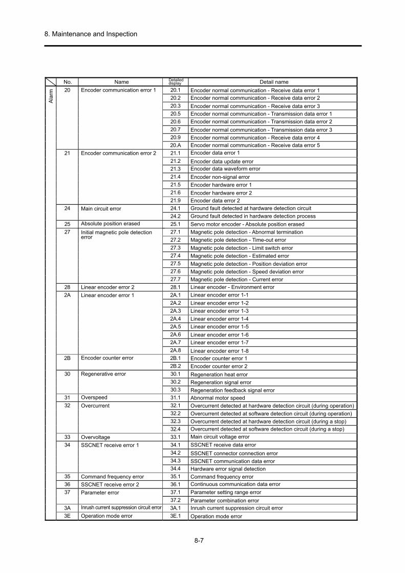
8. Maintenance and Inspection
8-7
20 20.1
2.02
3.02
5.02
6.02
7.02
9.02
A.02
21 21.1
2.12
3.12
4.12
5.12
6.12
9.12
24 24.1
2.42
25 25.1
27 27.1
2.72
3.72
4.72
5.72
6.72
7.72
28 28.1
2A 2A.1
2.A2
3.A2
4.A2
5.A2
6.A2
7.A2
8.A2
2B 2B.1
2.B2
30 30.1
2.03
3.03
31 31.1
32 32.1
2.23
3.23
4.23
33 33.1
34 34.1
2.43
3.43
4.43
35 35.1
36 36.1
37 37.1
2.73
3A 3A.1
3E 3E.1
No. Name Detaileddisplay Detail name
Ala
rm
Encoder communication error 1
Encoder communication error 2
Main circuit error
Absolute position erased
Initial magnetic pole detectionerror
Linear encoder error 2
Linear encoder error 1
Encoder counter error
Regenerative error
Overspeed
Overcurrent
Overvoltage
SSCNET receive error 1
SSCNET receive error 2
Command frequency error
Parameter error
Inrush current suppression circuit error
Operation mode error
Encoder normal communication - Receive data error 1
Encoder normal communication - Receive data error 2
Encoder normal communication - Receive data error 3
Encoder normal communication - Transmission data error 1
Encoder normal communication - Transmission data error 2
Encoder normal communication - Transmission data error 3
Encoder normal communication - Receive data error 4Encoder normal communication - Receive data error 5Encoder data error 1
Encoder data update errorEncoder data waveform error
Encoder non-signal error
Encoder hardware error 1
Encoder hardware error 2
Encoder data error 2
Ground fault detected at hardware detection circuit
Ground fault detected in hardware detection process
Servo motor encoder - Absolute position erased
Magnetic pole detection - Abnormal termination
Magnetic pole detection - Time-out error
Magnetic pole detection - Limit switch error
Magnetic pole detection - Estimated error
Magnetic pole detection - Position deviation error
Magnetic pole detection - Speed deviation error
Magnetic pole detection - Current error
Linear encoder - Environment error
Linear encoder error 1-1
Linear encoder error 1-2
Linear encoder error 1-3
Linear encoder error 1-4
Linear encoder error 1-5
Linear encoder error 1-6
Linear encoder error 1-7
Linear encoder error 1-8
Encoder counter error 2
Encoder counter error 1
Regeneration heat error
Regeneration signal error
Regeneration feedback signal error
Abnormal motor speed
Overcurrent detected at hardware detection circuit (during operation)
Overcurrent detected at software detection circuit (during operation)
Overcurrent detected at hardware detection circuit (during a stop)
Overcurrent detected at software detection circuit (during a stop)
Main circuit voltage error
SSCNET receive data error
SSCNET connector connection error
SSCNET communication data error
Hardware error signal detection
Command frequency errorContinuous communication data error
Parameter setting range error
Parameter combination errorInrush current suppression circuit error
Operation mode error

8. Maintenance and Inspection
8-8
42
42.3
42.8
42.9
42.A
45 45.1
46 46.1
2.64
3.64
5.64
6.64
47 47.1
2.74
50 50.1
2.05
3.05
4.05
5.05
6.05
51 51.1
2.15
52 52.1
3.25
4.25
5.25
54 54.1
56 56.2
3.65
63 63.1
2.36
70 70.1
2.07
3.07
5.07
6.07
7.07
A.07
B.07
C.07
D.07
E.07
F.07
71 71.1
2.17
3.17
5.17
6.17
7.17
9.17
A.17
42.142.2
No. Name Detaileddisplay Detail name
Ala
rm
Load-side encoder normalcommunication error 1
Servo control error(When using linear servo motor ordirect drive motor)
Fully closed loop control error(When using fully closed loopcontrol)
Main circuit device overheat
Servo motor overheat
Cooling fan error
Overload 1
Overload 2
Error excessive
Oscillation detection
Forced stop error
STO timing error
Load-side encoder initialcommunication error 1
STO1 off
Servo control error by position deviation
Servo control error by speed deviation
Servo control error by torque/thrust deviation
Fully closed loop control error by position deviation
Fully closed loop control error by speed deviation
Main circuit device overheat error
Servo motor temperature error 1
Servo motor temperature error 2
Thermistor disconnectedServo motor temperature error 3
Servo motor temperature error 4
Cooling fan stop error
Cooling fan speed reduction error
Thermal overload error 1 during operation
Thermal overload error 2 during operation
Thermal overload error 4 during operation
Thermal overload error 1 during a stop
Thermal overload error 2 during a stop
Thermal overload error 4 during a stop
Thermal overload error 3 during operation
Thermal overload error 3 during a stopExcessive pulse droop 1
Excessive pulse droop 2
Excessive pulse droop 3
Error excessive during 0 torque limit
Oscillation detection error
Over speed during forced stop
Basic estimated distance over during forced stop
Fully closed loop error by position deviation with stop command
STO2 off
Load-side encoder initial communication - Receive data error 1
Load-side encoder initial communication - Receive data error 2
Load-side encoder initial communication - Receive data error 3
Load-side encoder initial communication - Transmission data error 1
Load-side encoder initial communication - Transmission data error 2Load-side encoder initial communication - Transmission data error 3
Load-side encoder initial communication - Process error 1
Load-side encoder initial communication - Process error 2
Load-side encoder initial communication - Process error 3
Load-side encoder initial communication - Process error 4
Load-side encoder initial communication - Process error 5
Load-side encoder initial communication - Process error 6
Load-side encoder communication - Receive data error 1
Load-side encoder communication - Receive data error 2
Load-side encoder communication - Receive data error 3
Load-side encoder communication - Transmission data error 1
Load-side encoder communication - Transmission data error 2
Load-side encoder communication - Transmission data error 3
Load-side encoder communication - Transmission data error 4
Load-side encoder communication - Transmission data error 5
droop pulse
droop pulse
droop pulse
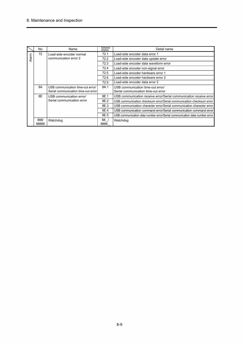
8. Maintenance and Inspection
8-9
72 72.1
2.27
3.27
4.27
5.27
6.27
9.27
8A 8A.1
8E 8E.1
2.E8
3.E8
4.E8
5.E8
888/88888
88._/8888._
No. Name Detaileddisplay Detail name
Ala
rm Load-side encoder normalcommunication error 2
USB communication time-out error/Serial communication time-out error
USB communication error/Serial communication error
Watchdog
Load-side encoder data error 1
Load-side encoder data update error
Load-side encoder data waveform error
Load-side encoder non-signal error
Load-side encoder hardware error 1
Load-side encoder hardware error 2
Load-side encoder data error 2
USB communication time-out error/Serial communication time-out error
USB communication receive error/Serial communication receive error
USB communication checksum error/Serial communication checksum error
USB communication character error/Serial communication character error
USB communication command error/Serial communication command error
USB communication data number error/Serial communication data number error
Watchdog

8. Maintenance and Inspection
8-10
91 91.1
92 92.1
3.29
95 95.1
2.59
96 96.1
2.69
3.69
99 99.1
2.99
9F 9F.1
2.F9
E0 E0.1
E1 E1.1
2.1E
3.1E
4.1E
5.1E
6.1E
7.1E
8.1E
E2 E2.1
E3 E3.1
2.3E
5.3E
E4 E4.1
E5 E5.1
2.5E
3.5E
E6 E6.1
E7 E7.1
E8 E8.1
2.8E
E9 E9.1
2.9E
3.9E
EA EA.1
EB EB.1
EC EC.1
ED ED.1
F0 F0.1
3.0F
F2 F2.1
2.2F
F3 F3.1
No. Name Detaileddisplay Detail name
Ala
rm
Servo amplifier overheat warningBattery cable disconnectionwarning
STO warning
Home position setting warning
Stroke limit warning
Battery warning
Excessive regeneration warning
Overload warning 1
Servo motor overheat warning
Absolute position counter warning
Parameter warning
ABS time-out warning
Servo forced stop warning
Controller forced stop warning
Cooling fan speed reductionwarning
Main circuit off warning
ABS servo-on warning
Other axis error warning
Overload warning 2
Output watt excess warning
Tough drive warning
Drive recorder - Miswriting warning
Oscillation detection warning
STO2 off detection
Main circuit device overheat warning
Encoder battery cable disconnection warning
Battery degradation
STO1 off detection
In-position warning at home positioning
Command input warning at home positioning
Servo off warning at home positioning
Forward rotation stroke end off
Reverse rotation stroke end off
Low battery
Battery degradation warning
Excessive regeneration warningThermal overload warning 1 during operation
Thermal overload warning 2 during operation
Thermal overload warning 3 during operation
Thermal overload warning 4 during operation
Thermal overload warning 1 during a stopThermal overload warning 2 during a stop
Thermal overload warning 3 during a stop
Thermal overload warning 4 during a stop
Servo motor temperature warningMulti-revolution counter travel distance excess warning
Encoder absolute positioning counter warning
Absolute position counter warning
Parameter setting range error warning
Time-out during ABS data transfer
ABSM off during ABS data transfer
SON off during ABS data transfer
Forced stop warningController forced stop warning
Decreased cooling fan speed warning
Cooling fan stop
Servo-on signal on during main circuit off
Bus voltage drop during low speed operation
Ready-on signal on during main circuit off
ABS servo-on warning
Other axis error warning
Overload warning 2
Output watt excess warning
Instantaneous power failure tough drive warning
Vibration tough drive warningDrive recorder - Area writing time-out warning
Drive recorder - Data miswriting warning
Oscillation detection warning

8. Maintenance and Inspection
8-11
8.4.2 Alarm Corrective Action
CAUTION
When an alarm has occurred, eliminate the cause, ensure safety, and
deactivate the alarm before restarting operation. Failure to do so may cause injury.
If [AL.25 Absolute position erased] occurs, make sure to perform home position setting again. Failure to do so may result in the servo motor working unexpectedly.
Turn off the servo at the same time an alarm occurs and disconnect the main circuit power supply.
POINT
When the following alarms occur, cancel the alarm and do not resume
operation by repeating. Doing so may cause failure of the servo amplifier and the servo motor. At the same time as the cause of the alarm occurrence is cleared, re-start operation after waiting a cooling time of 30 minutes or more.
• [AL.30 Regenerative error] • [AL.45 Main circuit device overheat] • [AL.46 Servo motor overheat] • [AL.50 Overload 1] • [AL.51 Overload 2]
For details regarding the corrective action for these alarms, refer to section 1.2 of "MELSERVO-J4 Servo Amplifier Instruction Manual (Troubleshooting) SH-030109". In addition, follow this instruction manual to clear the cause of the alarm. If MR Configurator2 is used, the cause of the alarm can be referenced.

8. Maintenance and Inspection
8-12
8.4.3 Warning Corrective Action
CAUTION
If [AL.E3 Absolute position counter warning] occurs, make sure to
perform home position setting again. Failure to do so may result in the servo motor working unexpectedly.
POINT
When the following warnings occur, repeatedly turn the power supply of the
servo amplifier on/off and do not restart operation. Failure to do so may cause failure of the servo amplifier and the servo motor. When the power supply of the servo amplifier is turned on/off while a warning occurs, restart operation after waiting a cooling time of 30 minutes or more.
• [AL.91 Servo amplifier overheat warning] • [AL.E0 Excessive regeneration warning] • [AL.E1 Overload warning 1] • [AL.E2 Servo motor overheat warning] • [AL.EC Overload warning 2]
For details regarding corrective action for these alarms, refer to section 1.3 of "MELSERVO-J4 Servo Amplifier Instruction Manual (Troubleshooting) SH-030109". In addition, follow this instruction manual to clear the cause of the warning. If MR Configurator2 is used, the cause of the warning can be referenced.

Appendix
Appendix-1
Appendix 1. Various Symbols
Appendix table 1 List of various symbols Ta
Td
TMa
TMd
TL
Tu
TF
TLO
Trms
TM
Tmmax
JL
JLO
JM
Nr
No
N
Vo
V
PB
Z1
Z2
: Acceleration torque
: Deceleration torque
: Motor torque necessary for acceleration
: Motor torque necessary for deceleration
: Load torque at motor shaft
: Unbalanced torque
: Load friction torque
: Load torque on load shaft
: Continuous effective load torque at motor shaft
: Motor rated torque
: Motor maximum torque
: Load moment of inertia at motor shaft
: Load moment of inertia on load shaft
: Rotor moment of inertia of the motor
: Motor rated speed
: Motor speed during maximum machine speed
: Motor speed
: Maximum machine high speed
: Machine speed
: Ball screw lead
: Number of gear teeth on motor shaft side
: Number of gear teeth on load shaft side
[Nm]
[Nm]
[Nm]
[Nm]
[Nm]
[Nm]
[Nm]
[Nm]
[Nm]
[Nm]
[Nm]
[kgcm2]
[kgcm2]
[kgcm2]
[r/min]
[r/min]
[r/min]
[mm/min]
[mm/min]
[mm]
Pf
fc1
fc
f0
Tpsa
Tpsd
Kp
Tp
∆0
∆c
P
tf
to
tst
tc
ts
m
ε
∆ε
∆S
: Number of feedback pulses
: Electronic gear output pulse frequency
: Electronic gear input pulse frequency
: Input pulse frequency during maximum machine speed
: Acceleration time of command pulse frequency
: Deceleration time of command pulse frequency
: Position loop gain
: Position loop time constant (Tp = 1/Kp)
: Feed length per electronic gear output pulse
: Feed length per electronic gear input pulse
: Feed length per rotation
: Number of command input pulses
: 1 operation cycle
: Positioning time
: Stop time
: Rated operation time
: Stop settling time
: Inertia ratio (m = JL/JM)
: Number of droop pulses
: Positioning accuracy
: Feed length per motor rotation
Example: For ball screw
[pulse/rev]
[pps]
[pps]
[pps]
[s]
[s]
[s-1]
[s]
[mm/pulse]
[mm/pulse]
[mm]
[pulse]
[s]
[s]
[s]
[s]
[s]
[pulse]
[mm]
[mm]
Z1
Reduction ratio 1/n =
Z2
Speed is reduced when 1/n < 1 and increased when 1/n > 1
With direct connection ∆S = PB
When reduction ratio is 1/n ∆S = PB1/n
Remarks 1. When the moment of inertia unit is expressed by GD2, GD2 = 4×J.
2. In the system of units, 1 kgm2 = 10000 kgcm2. 3. These various symbols are mainly for the servo amplifier and are described in relation to input and
output. Considered from the positioning controller side For example, it can be read as follows: Electronic gear input pulse frequency fc → Command output pulse frequency Feed length per electronic gear input pulse ∆c → Feed length per command output pulse (command minimum feed unit).

Appendix
Appendix-2
Appendix 2. Drive System Types
(1) Types of Motion Direction Depending on the servo motor, there are various types of machine drive systems, and all are used for different purposes (request accuracy, feed accuracy, travel distance, machine operation content during work, etc.). The following section shows the types of machine motion direction by classifying these drive system mechanisms while considering the connection with the servo motor. For linear movement, mm is used as the command unit, and for rotary movement, an angle or division number is used. The torque value turns out negative with vertical motion; thus, attention is required when reviewing the capacity.
Line
ar m
otio
n
Movement direction classification Horizontal direction Vertical direction (lifting)
PLG
Servomotor Deceleration gear
Ball screwMovable table
SM
B
W
Electromagnetic brake
DecelerationgearServo motor
Counterweight
Chain
Ball screw
Including the ball screw, this is the most common drive form used in the table feed or transportation machine of various machines using rack and pinion, belt, etc.
This drive form is used in the lift shaft of transportation machines or in robot vertical axes. As shown in the figure, a counterweight for load balance is often attached, and a motor with an electromagnetic brake is used to preventing dropping at the time of power failure.
Rot
atio
nal m
otio
n
Worm gear
Bevel gearServo motor
Timing belt
Servo motor
[Example 1. Consolidation by gear] [Example 2. Consolidation by belt]
This drive form is used in the axis of rotation of index tables, etc. The speed of the rotation shaft (axis of rotation of a table) is generally low, and use with a reduced speed by a gear or pulley teeth ratio is common.
Appendix figure 1 Types of motion direction

Appendix
Appendix-3
2) Actual drive system examples When performing positioning control with a position servo, the basis is the machine feed length per pulse. To calculate, it is necessary to decide the machine travel distance per motor rotation (symbol: ∆S; unit: mm). This section shows overview figures of various drive systems used for linear motion, as provided in 1), and their basic formulas.
Drive system type Features and basic formula
(1)
Bal
l scr
ew
Moving part
Ball screw lead (Symbol: Pn)Reduction ratio (1/n)
This typical drive system is used when performing highly accurate positioning over a comparatively short travel distance.
A smaller ball screw lead (shown in the figure to the left) results in higher precision and lower feed speed. (Provided that the drive servo is same.)
Basic formula
Feed length per motor rotation ∆S (mm) = PB(mm)1/n The following applies for direct coupling connections without a reducer ∆S = PB
(2)
Rac
k an
d P
inio
n Reduction ratio (1/n)
PCφ
Pinion part symbol
Module(Symbol: m)
Number of pinion teeth (Symbol: Z)
Rack pitch(Symbol: PL)
Rack
Rac
kP
inio
n
A form having carved teeth witha fixed pitch on a straight bar
A gear having carvedteeth with a fixed pitchin a circle
Pinion
This drive system is used for positioning over a comparatively long distance.
In most methods, the pinion side is generally fixed and the rack side moves, but sometimes the rack is fixed and the pinion side, including the motor part, is moved.
Basic formula
∆S (mm) = PL(mm)Z1/n or ∆S = PCφπ1/n
Appendix figure 2 Drive system (1)

Appendix
Appendix-4
Drive system type Features and basic formula
(3)
Tim
ing
belt
Belt pitch (Symbol: Pr)
Reduction ratio (1/n)
Number of pulley teeth(Symbol: Z)
Pulley teeth
Timing pulley
Timing pulley
Timing belt
Timing belt
Pu
lley
and
bel
tim
age
This drive system is used in a wide range from large transportation machines to precision machines.
Unlike V-belts or flat belts, which are frequently used with ordinary motors, feeding takes place by interlocking pulley and belt teeth. This means there are no errors due to slipping. However, the precision drops due to changes such as abrasion over the years, which depends on the material of the belt. Therefore, maintenance needs to be considered. Also, the belt pitch is manufactured in the inch system, and when considering the command pulse and feed length settings, caution must be taken because a fraction will occur with mm conversion.
Basic formula
∆S (mm) = PT (mm)Z1/n
(4)
Cha
in
Number of sprocket teeth(Symbol: Z)
Reduction ratio (1/n)
Chain pitch(Symbol: Pc)
Chain This drive system is mainly used in
large transportation machines. It is applicable when feeding over
long distances at high speeds. The chain pitch employs the inch
system similar to a timing belt, so care must be taken with regard to the feed length setting. Also, countermeasures must be taken considering the precision is affected by the occurrence of initial elongation.
Basic formula
∆S (mm) = PC (mm)Z1/n
Appendix figure 2 Drive system (2)

Appendix
Appendix-5
Drive system type Features and basic formula
(5)
Rol
l fee
d
Feed roll
Diameter of feed roll(Symbol: D)
Reduction ratio (1/n)
Workpiece (material)
In this system, a workpiece is fed (sent) by abrasion power after rotating the roll.
It is frequently used in fixed feeding represented by a roll feeder for a press machine, or for feeding film sheets, paper, etc. (drawing control, cutter, etc.).
To improve the positioning accuracy, it is necessary to prevent slippage between the roll and material, and process the roll into an exact circle.
π is basically an irrational number, thus compensation is required without avoiding the command pulse and feed length conversion fraction.
Basic formula
∆S (mm) = πD (mm)1/n
(6)
Car
t tra
vel
Cart
Cart drive part
Drive axis (both left and right wheels)
Diameter of drive wheel (Symbol: D)
Gear deceleration (1/n)
In this system, a servo motor is installed in the traveling cart and is used as a drive source.
As shown in the figure to the left, it is common for systems to rotate the servo motor by drive wheels. However, sufficient consideration is required to prevent slippage between the wheels and the rail.
Rack and pinion is used in systems other than that shown in the figure to the left, and a mechanism to move the pinion part at the fixing rack is also frequently used.
Basic formula (for the figure on the left)
∆S (mm) = πD (mm)1/n
Appendix figure 2 Drive system (3)

Appendix
Appendix-6
Appendix 3. Positioning Controller
Controller Positioning module type
Module type
FX2N-1PG FX2N-10PG FX2N-10GM FX2N-20GMQD75D1 QD75P1
QD75D2 QD75P2
QD75D4 QD75P4
Sys
tem
con
figur
atio
n
PC-to-PC network Note:
(1) A solid line between a controller and an amplifier shows a bus connection. (2) A dotted line shows a pulse train.
CC-LINK CPU
Module
Amplifier Motor
MELSECNET/H
CPU
Positioning module
Servo amplifier
Servo motor
I/F
sp
ecifi
catio
ns
Positioning module to amplifier
Pulse train / bus connection
Pulse train Pulse train
Command language (language used)
* Language response
+ ladder diagram Data table method + ladder diagram
Data table method + ladder diagram
Encoder specifications
INC/ABS method
INC/ABS INC/ABS INC/ABS INC/ABS
Maximum number of controllable axes 1 axis 1 axis 1 axis 2 axes 1 axis 2 axes 4 axes
Output pulse frequency 10 KPPS 100 KPPS 200 KPPS 200 KPPS QD75D: 1 MPPS (Differential driver) QD75P: 200 KPPS (Open collector)
Interpolation control function * * * Linear/circular * Linear/circular interpolation
Main control functions Position/speed Position/speed Position/speed Position/speedPosition/speed/position-speed switching/
speed-position switching/fixed feed
Positioning model selection points and merits
(1) Number of servo control axes
For small-scale axis
control
For small-scale axis
control
For control of 1 axis
For control of 2 axes
For control of 1 axis
For control of 2 axes
For control of 4 axes
(2) Sequence function (I/O points) (memory capacity)
All positioning data is for ladder diagrams and small-
scale I/O systems For small-scale I/O systems.
3.8 K steps when
individually connected to
FX2N or FX2NC
7.8 K steps when
individually connected to
FX2N or FX2NC
Any QCPU can be selected. Position data is acquired with the data table
method. (600 points/axis)
(3) Servo control function
For easy positioning
For easy positioning
1 axis
Linear and circular
interpolation functions for 2 axes are available
1 axis
Linear, circular interpolation control,
speed/position control, position/speed control,
fixed feed, etc.
(4) Cost performance, etc.
Compact, low-price system. Use in combination with CPU.
Compact, low-price system. Use in combination with CPU.
Compact, low-price system. Can also be used individually.
Compact, low-price system. Can also be used individually.
Compact (1 slot occupying 32 points), low cost. Ladder diagram between CPU and module, and pulse train, cable length restrictions between positioning module and servo amplifier. Electronic gears can be used for both QD75 and the servo amplifier. Position data is stored in flash ROM (battery not required).
Applicable servo amplifier series group
* MR-J2-Jr MR-J3-A
All other pulse train I/F methods can be used.
MR-J2-Jr MR-J3-A
All other pulse train I/F methods can be used.
Per
iphe
ral
equi
pmen
t
Programming tools and S/W package for positioning
GX Developer FX-20P FX-10P
E-20TP FX-PCS-VPS/WIN
(Windows version) GX Configurator-QP
<Special notes> 1. The MR-J3-T type is a CC-Link-compatible servo amplifier. The number of connectable servo amplifiers with 1
master module is 42 max. (when 1 station is occupied), and 32 when 2 stations are occupied.
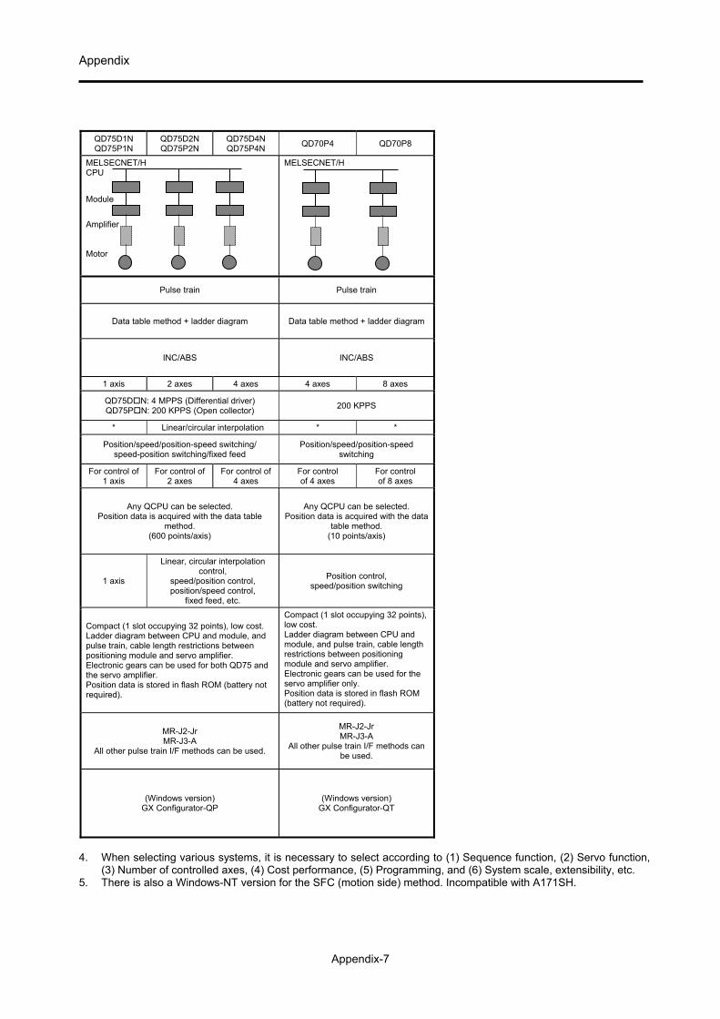
Appendix
Appendix-7
QD75D1N QD75P1N
QD75D2N QD75P2N
QD75D4N QD75P4N
QD70P4 QD70P8
MELSECNET/H CPU
Module
Amplifier Motor
MELSECNET/H
Pulse train Pulse train
Data table method + ladder diagram Data table method + ladder diagram
INC/ABS INC/ABS
1 axis 2 axes 4 axes 4 axes 8 axes
QD75DN: 4 MPPS (Differential driver) QD75PN: 200 KPPS (Open collector)
200 KPPS
* Linear/circular interpolation * *
Position/speed/position-speed switching/ speed-position switching/fixed feed
Position/speed/position-speed switching
For control of 1 axis
For control of 2 axes
For control of 4 axes
For control of 4 axes
For control of 8 axes
Any QCPU can be selected. Position data is acquired with the data table
method. (600 points/axis)
Any QCPU can be selected. Position data is acquired with the data
table method. (10 points/axis)
1 axis
Linear, circular interpolation control,
speed/position control, position/speed control,
fixed feed, etc.
Position control, speed/position switching
Compact (1 slot occupying 32 points), low cost. Ladder diagram between CPU and module, and pulse train, cable length restrictions between positioning module and servo amplifier. Electronic gears can be used for both QD75 and the servo amplifier. Position data is stored in flash ROM (battery not required).
Compact (1 slot occupying 32 points), low cost. Ladder diagram between CPU and module, and pulse train, cable length restrictions between positioning module and servo amplifier. Electronic gears can be used for the servo amplifier only. Position data is stored in flash ROM (battery not required).
MR-J2-Jr MR-J3-A
All other pulse train I/F methods can be used.
MR-J2-Jr MR-J3-A
All other pulse train I/F methods can be used.
(Windows version) GX Configurator-QP
(Windows version) GX Configurator-QT
4. When selecting various systems, it is necessary to select according to (1) Sequence function, (2) Servo function,
(3) Number of controlled axes, (4) Cost performance, (5) Programming, and (6) System scale, extensibility, etc. 5. There is also a Windows-NT version for the SFC (motion side) method. Incompatible with A171SH.

Appendix
Appendix-8
Controller Positioning module type
Module type
QD75M1 QD75M2 QD75M4 QD75MH1 QD75MH2 QD75MH4
Sys
tem
con
figur
atio
n
PC-to-PC network
Note: (1) A solid line between a controller and an amplifier shows a bus connection. (2) A dotted line shows a pulse train.
MELSECNET/H CPU Module
Amplifier Motor
CPU
Positioning module
Servo amplifier
Servo motor
I/F
sp
ecifi
catio
ns
Positioning module to amplifier
Pulse train / bus connection
Bus connection
Command language (language used)
* Data table method + ladder diagram
Encoder specifications
INC/ABS method
INC/ABS
Maximum number of controllable axes 1 axis 2 axes 4 axes -
Output pulse frequency High-speed serial communication method
Interpolation control function * Linear/circular interpolation -
Main control functions Position/speed/position-speed switching/
speed-position switching/fixed feed
Positioning model selection points and merits
(1) Number of servo control axes
For control of 1 axis
For control of 2 axes
For control of 4 axes
-
(2) Sequence function (I/O points) (memory capacity)
Any QCPU can be selected. Position data is acquired with the data table method. (600 points/axis) (A program for communication is also not required when using ABS.)
(3) Servo control function
1 axis
Linear, circular interpolation controlspeed/position control
position/speed control, fixed feed, etc.
-
(4) Cost performance, etc.
A ladder diagram is required between the CPU and the module, which are compact (1 slot occupies 32 points), low price, and easily wired, and an SSCNET bus and an all axes servo ON signal Y1 is required between the positioning module and the servo amplifier. Electronic gears inside the servo amplifier are not available (none). An electronic gear multiplying factor is required when using a taper. Some servo amplifier parameters can be set from the QD75M(H) side.
Applicable servo amplifier series group
* MR-J3-B
Per
iphe
ral
equi
pmen
t
Programming tools and S/W package for positioning
(Windows version) GX Configurator-QP
<Special notes>
1. The MR-J3-T type is a CC-Link-compatible servo amplifier. The number of connectable servo amplifiers with 1 master module is 42 max. (when 1 station is occupied), and 32 when 2 stations are occupied.

Appendix
Appendix-9
QD77MS2 QD77MS4 QD77MS16
SSCNET III(/H)
Bus connection
Data table method + ladder diagram
INC/ABS
2 axes 4 axes 16 axes
High-speed serial communication method
Linear/circular interpolation
Position/speed/position-speed switching/ speed-position switching/fixed feed
For control of 2 axes
For control of 4 axes
For control of 16 axes
Any QCPU can be selected. Position data is acquired with the data table method. (600 points/axis) (A program for communication is also not required when using ABS.)
Linear, circular interpolation control speed/position control
position/speed control, fixed feed, etc.
A ladder diagram is required between the CPU and the module, which are compact (1 slot occupying 32 points) and easily wired, and an SSCNET bus and an all axes servo ON signal Y1 is required between the positioning module and the servo amplifier. Electronic gears inside the servo amplifier are not available (none). An electronic gear multiplying factor is required when using a taper.
MR-J4-B, MR-J3-B
(Windows version) GX Works2, MR-Configurator2
4. When selecting various systems, it is necessary to select according to (1) Sequence function, (2) Servo function,
(3) Number of controlled axes, (4) Cost performance, (5) Programming, and (6) System scale, extensibility, etc. 6. By using the actuator I/F module (analog output), driving of a vector INV, another company's vector INV, etc., is
possible, as is torque control, etc., of tension control. 7. Fully closed loop control is possible with MR-J3-B-RJ006. 8. When using QD75M and QD75MH, perform everything, including servo amplifier side parameters, from the
positioning module side. Accordingly, programming is easy when software is used. Use of software is recommended especially for fixed parameters.

Appendix
Appendix-10
Controller Positioning module type
Module type
Q172HCPU Q173HCPU Q172DCPU Q173DCPU Q172DSCPU Q173DSCPU
Sys
tem
con
figur
atio
n
PC-to-PC network
Note: (1) A solid line between a controller and an amplifier shows a bus connection. (2) A dotted line shows a pulse train.
MELSECNET/H
CPU Module
Amplifier Motor
SSCNET III(/H)
CPU
Positioning module
Servo amplifier
Servo motor
I/F
sp
ecifi
catio
ns
Positioning module to amplifier
Pulse train / bus connection
Bus connection
Command language (language used)
* Dedicated language method + ladder diagram
(With NC language SV43) Dedicated language method +
ladder diagram
Encoder specifications
INC/ABS method
INC/ABS
Maximum number of controllable axes 8 axes 32 axes 8 axes 32 axes 16 axes 32 axes
Output pulse frequency High-speed serial communication method
Interpolation control function Linear/circular interpolation
Main control functions Position/speed/position-speed switching fixed feed/position tracking control/cam
Positioning model selection points and merits
(1) Number of servo control axes
For control of 8 axes max.
For control of 32 axes max.
For control of 8 axes max.
For control of 32 axes max.
For control of 16 axes max.
For control of 32 axes max.
(2) Sequence function (I/O points) (memory capacity)
Any QCPU can be selected. (With a multiple CPU system) When using Q25HCPU: I/O=256 points 34 ns/step
(3) Servo control function
Linear interpolation control of 4 axes, circular interpolation control of 2 axes Speed/position, constant speed control, fixed feed Position tracking control
(4) Cost performance, etc.
(1) Use of motion language, NC language (SV43) (2) SV13/SV22/SV43/SV54 can be selected (3) SSCNET method between controller and servo amplifier (4) ABS unlimited length positioning is possible
(1) Use of motion language (2) SV13/SV22 can be selected(3) SSCNET method between
controller and servo amplifier
(4) ABS unlimited length positioning is possible
Applicable servo amplifier series group
* MR-J3-B MR-J4-B
Per
iphe
ral
equi
pmen
t
Programming tools and S/W package for positioning
(Windows version) MT Developer, MT Developer2 (Windows version) MT Developer, MT Developer2
<Special notes>
1. The MR-J3-T type is a CC-Link-compatible servo amplifier. The number of connectable servo amplifiers with 1 master module is 42 max. (when 1 station is occupied), and 32 when 2 stations are occupied.

Appendix
Appendix-11
A171SH CPUN
A172SH CPUN
MR-J2S-CP MR-J3-T
MNET(II), MNET/B (MNET/10)
Bus connection -
Dedicated language method + ladder diagram
(With NC language SV43) Point table method/contact input
INC/ABS INC/ABS
4 axes 8 axes 1 axis
High-speed serial communication method
-
Linear/circular interpolation *
Position/speed/position-speed switching
fixed feed/position tracking control/cam Position
For control of 4 axes max.
For control of 8 axes max.
For control of 1 axis
A2SH or equivalent I/O=512 points
14 K step 25 μs/step
A2SH-S One phase or
equivalent I/O=1024 points
30K step 25 μs/step
All positioning data is acquired with the built-in point table method. For small-scale I/O systems.
Linear interpolation control of 4 axes, circular interpolation control of 2 axes
Speed/position, constant speed control, fixed feed
Position tracking control
For easy positioning
(1) Use of motion language, NC language (SV43)
(2) SV13/SV22/SV43/SV54 can be selected
(3) SSCNET method between controller and servo amplifier
(4) ABS unlimited length positioning is possible
Compact system with low cost. Can be used individually.
MR-J3-B MR-J3-T
(DOS/V, PC98) (MS-DOS version) For OS: SW*SRX-SV13/SW*NX-SV13 For peripherals: SW*SRX-GSV13/22
: SW*NX-GSV13/22 : SW**-CAMP
General-purpose personal computerbody component
4. When selecting various systems, it is necessary to select according to (1) Sequence function, (2) Servo function,
(3) Number of controlled axes, (4) Cost performance, (5) Programming, and (6) System scale, extensibility, etc. 5. There is also a Windows-NT version for the SFC (motion side) method. Incompatible with A171SH. 6. By using the actuator I/F module (analog output), driving of a vector INV, another company's vector INV, etc., is
possible, as is torque control, etc., of tension control. 7. Fully closed loop control is possible with MR-J3-B-RJ006. 8. When using QD75M and QD75MH, perform everything, including servo amplifier side parameters, from the
positioning module side. Accordingly, programming is easy when software is used. Use of software is recommended especially for fixed parameters.

Appendix
Appendix-12
Appendix 4. Terminology Adaptive vibration suppression control
If there is a specific resonance point in the mechanical system and if the servo system response is increased, the mechanical system may resonate (vibration or abnormal noise) at that resonance frequency. With the adaptive vibration suppression control function, the servo amplifier detects machine resonance and sets filter properties automatically, and then controls the vibration of the machine system.
Analog control <opposite: digital control>
Such control methods are implemented by a control circuit configured using analog elements such as an operational amplifier.
Absolute (absolute position) detector <opposite: increment detector>
With this detector, angle data per detector rotation can be output externally, and those products capable of producing 8- to 12-bit data over 360 degrees are commonly used. The servo motor detector is used when configuring the absolute position system in combination with the rotation amount counter to understand the position in one motor rotation. The figure below is a general structure of an absolute position detector. In this case, a 7-bit absolute position signal is output.
Sensor
Axis of rotation
Rotating glass disk ( )7 slits createdin a radial direction
Example of absolute position encoder structure
Primary delay time constant
This is the exponential time constant that shows the time until 63% of the final value is reached. (Refer to the diagram in the "Acceleration time constant" section.)
Position loop gain
Here, the response to the commands for position control are indicated. A summary position control block diagram with the speed control system as Gv(s) is shown here. Here, the position loop gain is as follows. Position loop gain = KpGv(s) = Kp (1/sec) The speed loop has feedback, so the gain is approximately 1. Here, the position loop gain is expressed as a position response level: Kp = ωpc (rad/sec).
Kp Gv(S) 1/SPosition
Position control Speed loop Machine
Inertia (moment of inertia)
Refer to the section on moment of inertia.

Appendix
Appendix-13
Impact drop For the value representing the fluctuating range of output to input commands in feedback control, when the load is changed stepwise, the temporal response characteristics are shown by the magnitude of the temporal variation as well as the duration. It is enabled especially when integral operations are included.
Response level
The position, speed, and current loop are present in the servo system, but traceability for the respective command is shown and generally indicates the speed response level.
Auto tuning (real-time auto tuning)
The performance of the machine (especially response level and stability) that drives the servo motor is dependent on the mechanical characteristics (moment of inertia, rigidity). Therefore, adjustment operation is required to get the best machine performance, and this operation is called tuning. Auto tuning means that the above tuning is performed automatically, and it indicates a function that automatically adjusts the speed loop gain and position loop gain, which are generally set by the servo amplifier. Real-time auto tuning indicates a function by which tuning is performed automatically by tracking the mechanical characteristics in particular even if there is a change during operation.
All-digital control (digital control)
This method allows control by a circuit that is configured by the microcomputer and its peripheral LSI as well as logic IC.
Regenerative brake
Usually, power is supplied from amplifier to the motor when driving a load by the motor. This status is called power running. Similar to the when the motor decelerates or a decreasing load is being driven, the rotation energy of the motor and the load flows to the amplifier when decelerating the load speed. This status is called regeneration. In a servo amplifier, regenerative energy is consumed by a capacitor and a resistor, and a regenerative brake torque is obtained. The regenerative brake torque is adjusted automatically according to the deceleration pattern, but a regenerative option is used for operations with frequent regenerative driving.
Rotation ripple
The ripple is generally slightly large due to the quick changes/variations in speed with respect to the command, and becomes small at high speeds.
Angular frequency (ω)
The number of cycles per second is expressed with Hz (hertz) as a unit to show a continuous sine wave, but here the angular frequency is expressed using an angle (radian). Frequency fHz is converted into 2πf rad/sec.
Acceleration time
The acceleration time is the time needed between the current speed and the next speed when changing the motor speed.

Appendix
Appendix-14
Acceleration time constant The acceleration time constant is the time from the start of acceleration to the completion of acceleration when accelerating from a motor stop status to a specific speed (rated speed, speed limit for parameters, etc.) * With acceleration patterns of a primary delay function, the acceleration time constant is the time until the
actual speed reaches 63.5% of the target speed.
Primary delay time constant
Acceleration pattern with a time constant of a primary delay
Acceleration time and acceleration time constant
tO: Acceleration time until reference speed=Acceleration time constant
t1: Acceleration time until speed N1
t2: Acceleration time until speed N2 Acceleration
Acceleration is the change in speed expressed as a ratio to acceleration time and becomes a slope with respect to the time of the change in speed. Also, acceleration is generally used during linear movement and is expressed by [m/s2].
Moment of inertia (inertia)
The moment of inertia is the quantity showing the rotation load of a rotating body. It is equivalent to the linear movement mass. Definitional formula: J=mr2 Here, J: Moment of inertia [kgcm2]
m: Mass [kg] r: Radius of rotation [cm]
Although GD2 is conventionally used as the quantity for expressing the moment of inertia, the following shows the relationship with r (radius) from the above formula expressed by 2r (diameter): GD2=m(2r)2=4J
Gain search The gain that improves the settling characteristics can be found automatically. (Enabled only in position control mode) While automatically changing the gain, the gain with the shortest settling time and smallest overshoot is searched for. This works well when a high level of adjustment is required. In addition, advance preparation before executing a gain search can be easily done with the gain search setting wizard.
Capacitor regeneration
Capacitor regeneration is a method of performing a regenerative operation by charging the regenerative energy into the main circuit capacitor. Because no heat is generated, repeated use is possible if the regenerative energy is smaller than the energy charged into the capacitor. However, only a small amount of energy can be charged into the capacitor, so applicability is limited to small-capacity models.

Appendix
Appendix-15
Differential transmission method When transmitting one signal, this method is a system for transmitting the signal and the polarity reversal signal simultaneously as a pair. The receiving side has excellent noise resistance and is used for transmission of high-speed signals, including pulse train I/O signals, in order to determine the logic of signals as a set. Generally, the sending side is called a driver while the receiving side is called a receiver, and a dedicated IC is used.
Sending side
Driver Receiver
Receiving side
Frequency response (characteristics)
This response quantitatively shows the speed response level. Showing until what frequency the motor can actually respond when the speed command is changed into sine wave as a micro speed command with roughly 10 r/min, the response is expressed by ωc [rad/sec] or fc (Hz). It is best to make the speed loop gain high so as to increase this frequency response level. However, if it becomes too high, vibration or instability will occur more easily due to rigidity of the mechanical system.
Stroke end The machine has a movable range (stroke), and position control is performed within this range. In addition, the machine needs to be forcibly stopped to protect it when this range is exceeded by mistake. The following two methods are available for setting the stroke end. (1) Install limit switches at both ends of the machine, and connect to the stroke end terminal of the positioning
controller or the servo amplifier. When these limit switches are operated, the servo motor will be stopped immediately.
(2) Set the range to the positioning controller parameters. Also called a soft limit, the range is checked when positioning starts, and the servo motor does not operate because of the occurrence of an error.
The operating range of the machine is restricted by the above machine limit (1) as well as the soft limit (2). The machine is stopped if the limit is exceeded and by starting in the opposite direction is thus freed. During the first operation, it is necessary to check the operation of the stroke end limit. Meanwhile, with the presence of a stroke end similar to a rotary table, the machine may have disadvantages. In this case, use the stroke end terminal of the positioning controller or the servo amplifier by short-circuiting. Also, with the response from the positioning controller, there are some items for which "Not used" is set to the parameters, depending on the model, and for some items the current position must be changed by a proper position.

Appendix
Appendix-16
Speed variation As a value representing the fluctuation range of the output speed for inputting commands in feedback control, the speed variation, generally based on the speed with a rated load, is the ratio of speed variation with no load or with a rated load value in the reverse direction. Although represented earlier as an offset related to the amplification factor (gain), when integral operation is incorporated, the speed variation is often dependent on the other causes. Therefore, it is necessary to focus rather on impact drop characteristics.
Speed loop gain
The speed loop gain represents the response level for commands in the speed control. If the constant determined by the motor is set to K1, the following applies:
K1 1(JL+JM) S
Kv
ω
Speed
Speed command + Speed control
ω
The reverse speed loop gain is as follows:K1・KV
Speed loop gain =JM+JL
KV: Speed amplifier gainJL: Load inertiaJM: Motor inertia
Dynamic brakes
This brake function is used to stop the machine quickly in case of power failure or a malfunction of the servo amplifier by obtaining a large brake torque from an electromagnetic brake. However, no holding torque during a stop is present. This function is built in to the MR-H servo amplifier. This function is not available in IM servos using an induced current electric motor.
Droop pulse
This position deviation (number of pulses) is retained inside the servo amplifier during position servo operation and is normally proportional to the pulse frequency command at low speeds. When positioning is completed, it is within ±1 pulse.
Hour
Pulse droop
Com
man
dpu
lse
freq
uenc
y
Ground fault
Ground fault refers to the status in which any of the main power supply circuit lines of the servo amplifier (P or N after diode commutation) and the power cable of a motor (U, V, W) is short-circuited to ground.
Resistance regeneration
This method obtains the braking torque by consuming regenerative energy after passing it through a resistor connected to the bus amplifier.
Droop pulse
Appendix
Appendix-17
Stop settling time The servo motor operates with a fixed deviation for the position command. Therefore, after completion of the commands for a stop, there is a delay until the servo motor stops. This delay time is called the stop settling time, which is ts time in the above droop pulse figure, and is expected to be roughly 3Tp. (Tp: Position loop time constant) When reviewing the operation pattern of the servo motor, it is necessary to consider the stop settling time.
Digital control (opposite: analog control)
This control method is implemented by control circuits that are configured with digital elements. Nowadays, in response to the increasing number of mathematical operations, methods that utilize processing with software using a micro-computer and micro-processor are often used. The advantage of the digital control method is that there are no offsets and temperature drifts, and performance is stable and repeatability is high.
Power regeneration
Power regeneration is a method for returning the regenerative energy to the power supply side through the bus amplifier. A dedicated module is required for return to the power supply side, but compared with the resistance regeneration method, power regeneration has the advantage of less heat generation and reduced installation dimensions as well as a larger amount of regenerative energy. For these reasons, power regeneration is mainly used in continuous regenerative operations such as for large-capacity models and elevated axes.
Electronic gear
The electronic gear changes the ratio of feedback pulses to command pulses. However, position resolution does not change because it is determined by the encoder. The changed ratio can be set to a fraction depending on the parameters. Unlike with a mechanical gear, the torque of the motor does not increase even if the reduction ratio is increased.
Electromagnetic brake
Electromagnetic brakes equipped in motors with electromagnetic brakes are non-exciting operation-type brakes used either for preventing dropping in case of a power failure or a malfunction of the servo amplifier due to vertical axis drive, or as protection during a stop.
Torque linearity
The torque linearity shows the relationship with the torque generated by the motor in response to the torque command. Especially when using for torque control, there is a dead band near zero torque. Also, the magnetic energy of the magnet used in the motor changes according to the temperature. As a result, the torque linearity is also affected. For ferrite magnets it is -0.2/°C, and for rare-earth magnets it is -0.33/°C.
Backlash compensation
There is an essentially dead band (clearance) in the mechanical system. This dead band is called the backlash. If backlash is present, that part of the machine will not operate even if the servo motor rotates. Therefore, an error occurs in the part with the backlash in the current position of the positioning controller and the position of the machine. However, this error is not cumulative. The following backlash compensation function is used to compensate this error. If the backlash amount is set to the parameters of the positioning controller, an extra pulse train signal equivalent to the part having the backlash is output only when the rotation direction of the servo motor is changed. The motor will rotate at this time, but the machine will not move. In addition, the positioning controller will not count this pulse train signal as the current position. In this way, the position of the machine and the current position of the positioning controller are matched, and the error due to the backlash will be corrected. (1) Backlash compensation is effective after executing the home position return. (2) When backlash settings have changed, a home position return must always be executed.

Appendix
Appendix-18
Power rate The power rate represents the speed when the motor accelerates itself by increasing the output that can be issued by the motor with a constant-torque motor. This rate is defined as follows.
TR2
Q= ×10 [kW/s] JM TR: Motor output torque [Nm] JM: Moment of inertia of motor [kgcm2]
Proportional control
Proportional control is also called P control. The manipulated value Y is proportional to the deviation value ε; thus it is expressed by Y=εKp. If a mechanically locked motor becomes stuck even for 1 pulse after positioning completion, a large current passes through the motor and tries to compensate for the position mismatch. To avoid this, if proportional control is performed simultaneously with positioning completion, the torque gain decreases and the current is suppressed. Also, it is possible to suppress vibration during servo-lock using proportional control. In this proportional control, the operation takes place immediately to prevent deviation with an unexpected disturbance. However, it is not possible to completely reduce deviation for continuous disturbances. This is because the control system continues to operate in a corrective manner with a continuous disturbance. Therefore, deviation is required to a certain extent.
Feedback control
Feedback control is considered the control that detects the difference between the command and the actual speed using a closed loop, and then the command value is corrected in order to reduce this difference.
Feed forward control
Feed forward control refers to control that sends a speed command before a droop pulse increase when the pulse command is input during position loop control.
Bus voltage
Voltage that is rectified by a power converter, once converted into DC, is again converted into AC by the inverter, and drives the AC motor. The voltage of the DC portion is called bus voltage.
Machine analyzer
The servo amplifier vibrates the servo motor for approximately 0.1 to 2 seconds at a random torque, and the speed is measured at that time. Then, MR Configurator2 analyzes the reading of the torque and speed data from the servo amplifier. As a result, the response frequency characteristics of the speed for the motor torque of a machine can be measured. By looking at these characteristics, it is possible to understand at what frequency the mechanical system has a resonance point, which allows setting of the machine vibration suppression filter to be performed easily.
Start the machine
analyzerTorque excitation
Setupsoftware
Torquespeed data
Servoamplifier
Speed feedbackServomotor
Machine

Appendix
Appendix-19
Model adaptive control and real-time auto tuning Model adaptive control is Mitsubishi's independent control logic developed on the basis of current control theory. With this control, the model loop and actual loop gain are automatically set on the basis of the load inertia obtained by real-time auto tuning, and the settings for machine stability with an increased response to commands can be configured.
Com
mand
Ideal model part
Load
Load
Actual servomotor andmachine
Actual loop part
Real-time autotuning part
Explanation As shown in the above figure, the model adaptive control within the control logic consists of three parts.
(1) Ideal model part (2) Real-time auto tuning part (3) Actual loop part (disturbance suppression part)
The ideal model part adjusts the most appropriate gain for the inertia estimated through real-time auto tuning. Because there is no machine disturbance or backlash, each gain shows good characteristics even with fast responses. Model side position loop gain (PG1) is used in the calculation of droop pulses or the stop settling time. Real-time auto tuning calculates the inertia of load from the current and the time during acceleration/deceleration. This is extremely effective in machines in which the inertia changes greatly, such as transportation machines. Manual setting is also possible in machines where real time auto tuning is not possible (when the unbalance is large in the vertical axis, when the load inertia exceeds the permissible value, when the droop pulse of interpolation operation is to be kept constant). The actual loop part (disturbance control unit) is designed based on conventional PI control, and when an error occurs in the model speed created in the ideal model part and actual motor speed due to the disturbance torque, a torque command is sent from the actual loop side in order to follow the model speed from the actual loop part. Although a high gain is set for imparting the disturbance suppression effect, vibrations occur if it is too high. The value of this gain is also adjusted to the appropriate level with respect to the inertia ratio. The appropriate gain value of the model part and the actual loop part is set on the basis of the set real time auto tuning response setting value. Therefore, when the response is to be raised, the response setting value must be reviewed. Because the model adaptive control is configured as mentioned above, easily responding to complex machine adjustments is possible, a feat which was not possible with the conventional method and in extreme frequency applications.

Appendix
Appendix-20
RISC RISC is the abbreviation of "Reduced Instruction Set Computer" and is a new type of computer wherein commands and the command format are simplified compared to conventional micro-processors (called CISC in regard to RISC). Because of this, it is possible to increase the processing speed, which means execution of enormous operation processing, such as model adaptive control of a servo in real time, is possible.

Appendix
Appendix-21
Appendix 5. Protection Model of Motor
(1) Classification according to JIS For the symbols of the protection model of the electric motor, arrange the symbols in Appendix table 6.1 as the first symbols and those in Appendix table 6.2 as the second symbols after JP. Example: JP 4 4
Second symbol (Appendix table 6.2) First symbol (Appendix table 6.1)
Note: Insert W between JP and the first symbol for outdoor use, E for explosion-proof types, and C for
protection against other forms of harmful air. Example JPW44: E and C are not 1EC standards.
Appendix table 6.1 Protection models for humans and solid foreign matter (first symbol)
Model Symbol Description
Non-protection
type
0 A structure in which special protection is not provided against contact with the human body or invasion of solid foreign matter.
Half-protection
type
1 A structure in which a large part of a human body, for example, a hand, is prevented from accidentally touching the rotating part or the guidance section inside the machine.
Protection type
2 A structure that prevents invasion of solid foreign matter exceeding a diameter of 50 mm. A structure that prevents fingers from touching the rotating part or the conductive part inside the machine. A structure that prevents invasion of solid foreign matter exceeding a diameter of 12 mm.
Totally enclosed
type
4 A structure in which tools or wires with a minimum width and minimum thickness more than 1 mm are prevented from touching the rotating part or the dielectric part inside the machine. A structure that prevents invasion of solid foreign matter exceeding a diameter of 1 mm. However, intakes and exhausts of drainage holes and cooling fans are better if the structure of symbol 2 is used.
Dust-proof type
5 A structure that prevents any matter from touching the rotating part or the dielectric part inside the machine. A structure that prevents the invasion of dust as much as possible and assists normal operation without trouble even if there is any invasion.
Appendix table 6.2 Protection model for intrusion of water (second symbol)
Model Symbol Description
Non-protection
type
0 A structure with no special protection against the intrusion of water.
Drip-proof type
2 A structure in which a drop of water dropped in a vertical direction within 15° has no harmful effects.
Rain-proof type
3 A structure in which a drop of water dropped in a vertical direction within 60° has no harmful effects.
Splash-proof type
4 A structure in which a drop of water from any direction has no harmful effects.
Jet-proof type
5 A structure in which a jet flow from any direction has no harmful effects.
Breakwater wave type
6 A structure in which a strong jet flow from any direction has no harmful effects.
Dust-proof type
7 A structure in which being drenched or immersed in water for a specified time has no harmful effects even if there is water intrusion.
Sub- mersible
type
8 A structure that operates normally under water.

Appendix
Appendix-22
(2) Classification according to IEC For protection models of electric motors, arrange the symbols in Appendix table 6.3 as the first symbols and those in Appendix table 6.4 as the second symbol after IP. Example: IP 6 5
Second symbol (Appendix table 6.4) First symbol (Appendix table 6.3)
Appendix table 6.3 Degrees of protection for invasion of solid foreign matter (first symbol)
Model Symbol Description
Unprotected 0 Unprotected
Diameter ≥ 50 mm
1 Protects from invasion of solid foreign matter as small as 50 mm, for example, a hand.
Diameter ≥ 12.5 mm
2 Protects from invasion of solid foreign matter as small as 12 mm, for example, a finger.
Diameter ≥ 2.5 mm
3 Protects from invasion of solid foreign matter having a diameter of 2.5 mm or more, for example, the tip of a tool or a wire.
Diameter ≥ 1.0 mm
4 Protects from invasion of solid foreign matter having a diameter of 1.0 mm or more, for example, a wire or flake.
Dust-proof type
5 Protects from dust. No invasion of dust will disturb normal operation.
Dust-resistant type
6 Safe dustproof structure. Invasion of dust is impossible.
Appendix table 6.4 Degrees of protection for intrusion of water (second symbols)
Model Symbol Description
Unprotected 0 Unprotected
Vertical drop 1 Protects from a drop of water dropped vertically, for example, condensation.
Drop (15 degrees deviation)
2 Protects from a drop of water in a range of 15 degrees from vertical.
Sprinkles 3 Protects from spray in a range of 60 degrees from vertical.
Splashes 4 Protects against water droplets from all directions.
Jet 5 Protects against strong jets of water from all directions.
Powerful jet 6 Protects against strong jets of water, such as waves. No intrusion of water will disturb normal operation.
Temporary submersion
7 Even if submerged between 150 mm and 1 m, there is no intrusion of water that will disturb normal operation.
Continuous submersion
8 Underwater usage is possible. Can be used for a long period of time under water.

Appendix
Appendix-23
Appendix 6. QD75D1N Setting Values (Training Machine)
(1) Parameter (Axis 1)
Item Setting value Remarks
Basic parameter 1
Unit setting 0 mm Number of pulses per rotation 1 pulse Travel distance per 1 revolution 10.0 μm Unit scaling 1 ×1 Pulse output mode 1 CW/CCW mode
Rotation direction setting 0 Current value increment with forward rotation pulse output
Bias speed at start 0.00 mm/min
Basic parameter 2
Speed limit value 600000.00
mm/min
Acceleration time 0 100 ms Deceleration time 0 100 ms
Detailed parameter 1
Backlash compensation 0.0 μm Software stroke limit upper limit value 214748364.7 μm Software stroke limit upper lower value -214748364.8 μm
Software stroke limit selection 0 Multiply current feed value by software limit
Software stroke limit enable/disable setting 1 Disabled Command in-position range 100.0 μm Torque limit setting value 300 % M code ON signal output timing 0 WITH mode Speed switchover mode 0 Standard speed switchover mode Interpolation speed specification method 0 Composite speed
Current feed value at speed control 0 Does not replace the current feed value
Lower limit 1 Positive logic Upper limit 1 Positive logic Drive unit ready 0 Negative logic Stop signal 0 Negative logic External command 0 Negative logic Zero-point signal 0 Negative logic Proximity signal 0 Negative logic Manual pulse generator input 0 Negative logic Command pulse signal 0 Negative logic Deviation counter clear 0 Negative logic Manual pulse generator input selection 0 Phase A and B mode
Speed/position function selection 0 Speed/position switching control (INC mode)

Appendix
Appendix-24
Item Setting value Remarks
Detailed parameter 2
Acceleration time 1 10 ms Acceleration time 2 50 ms Acceleration time 3 1000 ms Deceleration time 1 10 ms Deceleration time 2 50 ms Deceleration time 3 1000 ms
JOG speed limit value 600000.00
mm/min
JOG operation acceleration time selection 0 100 JOG operation deceleration time selection 0 100 Acceleration/deceleration processing selection
0 Trapezoid acceleration/deceleration processing
S-curve ratio 100 % Sudden stop deceleration time 1000 ms Stop group 1 sudden stop selection 0 Normal deceleration stop Stop group 2 sudden stop selection 0 Normal deceleration stop Stop group 3 sudden stop selection 0 Normal deceleration stop In-position signal output time 300 ms Circular interpolation permissible error range
10.0 μm
External command function selection 0 External positioning start
Home position
return basic parameter
Home position return method 0 Near-point dog signal method
Home position return direction 1 Negative direction (address decreasing direction)
Home position address 0.0 μm Home position return speed 5000.00 mm/min Creep speed 1000.00 mm/min
Home position return retry 1 Retry home position return with limit switch
Home position return
detailed parameter
Home position return dwell time 0 ms Travel distance after proximity dog signal turned on
0.0 μm
Home position return acceleration time selection
3 1000
Home position return deceleration time selection
3 1000
Home position shift distance 0.0 μm Home position return torque limit value 300% Deviation counter clear signal output time 11 ms Speed specification at home position shift time
0 Home position return speed
Dwell time at home position return retry 0 ms

Appendix
Appendix-25
(2) Positioning data (Axis 1)
Data No.
Operation pattern
Control method
Acceleration time
Deceleration time
Interpolationtarget axis
Positioning address
Command speed
Dwell time
M code
1 1: Continuous 02: INC linear 1 0: 100 ms 0: 100 ms - -50000.0 50000.00 500 02 1: Continuous 02: INC linear 1 0: 100 ms 0: 100 ms - 50000.0 50000.00 500 03 1: Continuous 02: INC linear 1 0: 100 ms 0: 100 ms - -100000.0 100000.00 500 04 1: Continuous 02: INC linear 1 0: 100 ms 0: 100 ms - 50000.0 50000.00 500 05 1: Continuous 02: INC linear 1 0: 100 ms 0: 100 ms - -100000.0 100000.00 500 36 1: Continuous 02: INC linear 1 0: 100 ms 0: 100 ms - 50000.0 50000.00 500 07 1: Continuous 02: INC linear 1 0: 100 ms 0: 100 ms - -50000.0 50000.00 500 08 1: Continuous 02: INC linear 1 0: 100 ms 0: 100 ms - 150000.0 200000.00 500 09 1: Continuous 02: INC linear 1 0: 100 ms 0: 100 ms - -75000.0 100000.00 500 0
10 1: Continuous 02: INC linear 1 0: 100 ms 0: 100 ms - -75000.0 1000.00 1000 011 1: Continuous 02: INC linear 1 0: 100 ms 0: 100 ms - 75000.0 100000.00 500 012 1: Continuous 02: INC linear 1 0: 100 ms 0: 100 ms - 75000.0 1000.00 1000 013 1: Continuous 02: INC linear 1 0: 100 ms 0: 100 ms - -150000.0 200000.00 1000 014 0: Exit 02: INC linear 1 0: 100 ms 0: 100 ms - 150000.0 200000.00 2000 015 16 17 18 19 20 1: Continuous 02: INC linear 1 0: 100 ms 0: 100 ms - 0.0 1000.00 0 021 0: Exit 83: LOOP 0: 100 ms 0: 100 ms - 0.0 0.00 0 6553522 1: Continuous 02: INC linear 1 0: 100 ms 0: 100 ms - -50000.0 50000.00 500 023 1: Continuous 02: INC linear 1 0: 100 ms 0: 100 ms - 50000.0 50000.00 500 024 1: Continuous 02: INC linear 1 0: 100 ms 0: 100 ms - -100000.0 100000.00 500 025 1: Continuous 02: INC linear 1 0: 100 ms 0: 100 ms - 50000.0 50000.00 500 026 1: Continuous 02: INC linear 1 0: 100 ms 0: 100 ms - -100000.0 100000.00 500 327 1: Continuous 02: INC linear 1 0: 100 ms 0: 100 ms - 50000.0 50000.00 500 028 1: Continuous 02: INC linear 1 0: 100 ms 0: 100 ms - -50000.0 50000.00 500 029 1: Continuous 02: INC linear 1 0: 100 ms 0: 100 ms - 150000.0 200000.00 500 030 1: Continuous 02: INC linear 1 0: 100 ms 0: 100 ms - -75000.0 100000.00 500 031 1: Continuous 02: INC linear 1 0: 100 ms 0: 100 ms - -75000.0 1000.00 1000 032 1: Continuous 02: INC linear 1 0: 100 ms 0: 100 ms - 75000.0 100000.00 500 033 1: Continuous 02: INC linear 1 0: 100 ms 0: 100 ms - 75000.0 1000.00 1000 034 1: Continuous 02: INC linear 1 0: 100 ms 0: 100 ms - -150000.0 200000.00 1000 035 1: Continuous 02: INC linear 1 0: 100 ms 0: 100 ms - 150000.0 200000.00 2000 036 0: Exit 84: LEND 0: 100 ms 0: 100 ms - 0.0 0.00 0 037 0: Exit 02: INC linear 1 0: 100 ms 0: 100 ms - 0.0 1000.00 0 0
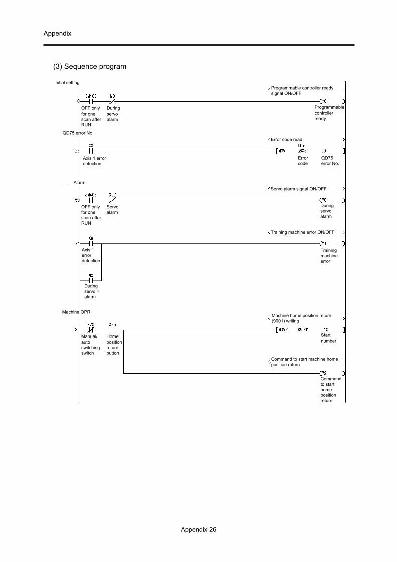
Appendix
Appendix-26
(3) Sequence program
Commandto starthomepositionreturn
Command to start machine homeposition return
Machine home position return(9001) writing
Initial setting
OFF onlyfor onescan afterRUN
Duringservo alarm
QD75 error No.
Axis 1 errordetection
Alarm
Servoalarm
OFF onlyfor onescan afterRUN
Axis 1errordetection
Duringservo alarm
Machine OPR
Manual/autoswitchingswitch
Homepositionreturnbutton
Programmable controller readysignal ON/OFF
Programmablecontrollerready
Error code read
QD75error No.
Errorcode
Servo alarm signal ON/OFF
Duringservo alarm
Training machine error ON/OFF
Startnumber
Trainingmachineerror

Appendix
Appendix-27
Positioning operation
Startbutton
One cycle/continuousswitchingswitch
Manual/autoswitchingswitch
Positioning data No. 1 setting
Startnumber
Positioning data No. 20 setting
Startnumber
Command to start positioning operation
Commandto startpositioning
Conversion of positioning startcommand into pulse form
Positioningstartcommandpulse
Holding of positioning start command
Storage ofpositioningstartcommand
Axis 1:Positioningstart
Axis 1startcompletion
JOG in-operationflag
Positioningstartcommandpulse
Commandto startpositioning
Commandto starthomepositionreturn
One cycle/continuousswitchingswitch

Appendix
Appendix-28
Setting of positioning start number
Storage ofpositioningstartcommand
Startnumber
Positioningstartnumber
Execution of positioning start
Axis 1:Positioningstart
Positioning start commandstorage OFF
Storage ofpositioningstartcommand
Positioning start signal OFF
Axis 1:Positioningstart
JOG in-operation flag ON
JOG in-operationflag
End of JOG operation
JOG in-operationflag
ReverserotationJOGbutton
ForwardrotationJOGbutton
ForwardrotationJOGbutton
ReverserotationJOGbutton
Axis 1BUSY
Manual/autoswitchingswitch
QD75ready
ForwardrotationJOGbutton
JOG operation
Axis 1errordetection
Axis 1BUSY
Axis 1startcompletion
Axis 1:Positioningstart
ReverserotationJOGbutton

Appendix
Appendix-29
JOG in-operationflag
ForwardrotationJOGbutton
JOG in-operationflag
Axis 1:ReverserotationJOGstart
JOG in-operationflag
Axis 1:ForwardrotationJOGstart
ReverserotationJOGbutton
Stop
Stopbutton
Trainingmachineerror
Axis 1BUSY
Stopcommandsignal
Stopbutton
Axis 1BUSY
Axis 1:Axis stop
Axis 1:Axis stop
Axis stop signal OFF by axis stop
Execution of stop
Stopcommandsignal
Conversion of stop commandinto pulse form
Axis 1:ReverserotationJOG start
Execution of reverse rotationJOG operation
Axis 1:ForwardrotationJOG start
Execution of forward rotationJOG operation
JOGoperatingspeed(lower 16-bit)
JOG operating speed writing
JOGoperatingspeed(lower16-bit)
Setting of JOG operating speed(5000.00 mm/min)

Appendix
Appendix-30
Memo

AC Servo School TextAC Servo Practice Course
(MELSERVO-J4)
AC Servo School Text AC Servo Practice Course (MELSERVO-J4)
AC Servo School TextAC Servo Practice Course (MELSERVO-J4)
Specifications subject to change without notice.
When exported from Japan, this manual does not require application to theMinistry of Economy, Trade and Industry for service transaction permission.
HEAD OFFICE : TOKYO BUILDING, 2-7-3 MARUNOUCHI, CHIYODA-KU, TOKYO 100-8310, JAPANNAGOYA WORKS : 1-14 , YADA-MINAMI 5-CHOME , HIGASHI-KU, NAGOYA , JAPAN
MODEL
MODELCODE
SH-030146ENG-A (1509) MEE