series 2 regenerative blowers operating and maintenance · pdf file ·...
TRANSCRIPT
2395 Apopka Blvd. • Apopka, FL 32703 • Phone: 877-347-4788 • Fax: 407-886-6787 • [email protected] • PentairAES.com
Series 2 Regenerative BlowersOperating and Maintenance Instructions
(Part Nos. SST10–SST80)

Table of Contents Page
Safety Messages . . . . . . . . . . . . . . . . . . . . . . . . . . . . . . . . . . . . . . . . . . . . .2
Guidelines for Product Use . . . . . . . . . . . . . . . . . . . . . . . . . . . . . . . . . . . .2
Wiring . . . . . . . . . . . . . . . . . . . . . . . . . . . . . . . . . . . . . . . . . . . . . . . . . . . . .2
Operating and Maintenance Instructions . . . . . . . . . . . . . . . . . . . . . . . . .2
Description . . . . . . . . . . . . . . . . . . . . . . . . . . . . . . . . . . . . . . . . . . . . .2
Application/Installation Environment . . . . . . . . . . . . . . . . . . . . . . . . . .2
Installation . . . . . . . . . . . . . . . . . . . . . . . . . . . . . . . . . . . . . . . . . . . . . . . . . .3
Minimum Clearances . . . . . . . . . . . . . . . . . . . . . . . . . . . . . . . . . . . . .3
Installation Procedure. . . . . . . . . . . . . . . . . . . . . . . . . . . . . . . . . . . . . . . . .3
Startup . . . . . . . . . . . . . . . . . . . . . . . . . . . . . . . . . . . . . . . . . . . . . . . . . . . . .3
Potential Risks . . . . . . . . . . . . . . . . . . . . . . . . . . . . . . . . . . . . . . . . . . . . . . .3
Maintenance and Servicing . . . . . . . . . . . . . . . . . . . . . . . . . . . . . . . . . . . .3
Troubleshooting Chart . . . . . . . . . . . . . . . . . . . . . . . . . . . . . . . . . . . . . . . .5
Exploded View of Blower . . . . . . . . . . . . . . . . . . . . . . . . . . . . . . . . . . . . . .6
Standard Warranty . . . . . . . . . . . . . . . . . . . . . . . . . . . . . . . . . . . . . . . . . . .7
Safety MessagesSafety is important to us. We have included safety messages throughout this manual and for your protection. Please read and follow all directions.
A safety message has a safety alert symbol followed by an explanation of what the hazard is, what can happen and what you should do to avoid injury. This is the safety alert symbol:
The safety alert symbol and "WARNING" or "CAUTION" will precede all safety messages:
WARNINGYou will be killed or seriously injured if you don't follow instructions.
CAUTIONYou can be killed or seriously injured if you don't
follow instructions.
ELECTRICAL SHOCK HAZARDDisconnect electrical power at the circuit breaker or fuse box before installing this product. Install where it will not come into contact with water or other liquids and where it will be weather protected. Electrically ground this product. Failure to follow these instructions can result in death, fire or electrical shock.
Guidelines for Product Use• Pump only clean, dry air. Do not pump flammable or explosive gases or use
in an atmosphere that contains such gases.
• Operate at 32–104°F (0–40°C).
• Protect unit from dirt and moisture.
• Blower must be installed with the properly sized inlet (included) and in-line filters, gauges and relief valves to protect against dirt and overheating.
WiringMake sure the wiring is done by a qualified electrician familiar with NEMA MG2 safety standards, national electric code and all local safety codes. Select fuses, motor protective switches or thermal protective switches to provide protection. Fuses act as short circuit protection for the motor, not as protection against overload. Incoming line fuses help to withstand the motor's starting current. Motor starters with thermal magnetic overload or circuit breakers protect the motor from overload or reduced voltage conditions. See the wiring diagram(s) attached to the product for required electrical information.
Check that the power source is correct in order to properly operate a dual-voltage motor. Only SST10 and SST15 are shipped from the factory wired for 115V unless otherwise requested.
Operating and Maintenance InstructionsDescriptionAll regenerative blowers are dynamic compression devices and utilize a noncontacting impeller to accelerate the gas and a specially designed housing to compress the gas. Cooling is accomplished by using the motor fan to blow air over the housing. In larger models, the housing is specially designed with cooling fins to allow a wider range of operation. Both the inlet and outlet ports have built-in silencers and mesh screens. Both the inlet and outlet have an inside connection thread corresponding to DIN ISO 228. On larger units, multiple suction and discharge connection configurations may be available.
The blower shares a bearing with the motor. The seal between the bearing and the motor is not gas tight in most models, therefore these blowers are not recommended for handling of toxic or explosive gases. Contact Aquatic Eco-Systems for additional options if explosive or toxic gases will be handled.
A full range of accessory items are available, including vacuum or pressure relief valves, check valves, suction filters, motor starters, vacuum/pressure cross-over valves and in-line filters.
Application/Installation Environment
CAUTIONThese blowers are designed for use in general industry. Suitable personnel protection according to OSHA requirements is provided, but the equipment should not be operated in residential settings. Sweetwater® blowers can be operated as either vacuum pumps or compressors. They are suitable for use with air having a relative humidity up to 90%, but not generally suitable for handling corrosive or erosive gases. Special versions for toxic or aggressive gases may be available. Use of the standard blower in aggressive environments may cause damage to the blower or exposure to gases being handled in the local environment.
CAUTION Dangerous (flammable or explosive) or aggressive (corrosive) gases should not be handled by the standard blower.
Handling of flammable or aggressive gases and vapors may be possible by using a specially configured or modified blower. Contact factory for additional information. The standard blower is not suitable for operation in explosive environments as defined by NFPA 70. Contact factory for assistance.
CAUTIONThe ambient and suction temperatures should be between 40º and 104ºF. For temperatures outside this range, please contact the factory. The maximum permissible pressure difference for vacuum or pressure is dependent on the motor rating and power supply frequency. Operation at an ambient temperature of 104ºF (40ºC) is the maximum permissible, and will result in a reduction of 10% of maximum vacuum or pressure attainable by the unit.
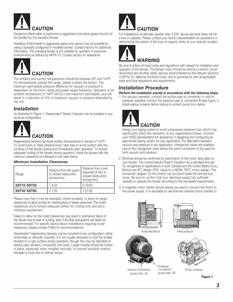
InstallationAs illustrated in Figure 1, Sweetwater® Series 2 blowers can be installed in any physical configuration.
CAUTIONRegenerative blowers can have surface temperatures in excess of 120ºF. To avoid burns or other physical injury, take care to avoid contact with the surfaces of the blower during and immediately after operation. To ensure adequate cooling of the blower during operation, install the blower with the minimum clearance as indicated in the table below.
Minimum Installation Clearances
RangeDistance from fan guard to closest obstruction (inches/mm)
Distance from cover (opposite of fan) to closest obstruction (inches/mm)
SST10–SST35 1.4/34 0.79/20
SST40–SST80 2.1/53 1.57/40 Please note that it may be desirable, where possible, to allow for larger clearances to allow access for maintenance or repair personnel. The noted clearances are to ensure adequate airflow for cooling only and are a minimum requirement.
Failure to allow for the noted clearances may result in premature failure of the blower due to lack of cooling, even if all other precautions are taken as recommended. For specific advice about installations requiring closer clearances, please contact PAES for recommendations.
Sweetwater® regenerative blowers can be mounted in any configuration, either horizontally or vertically mounted. It is not usually necessary to bolt the smaller blowers to a rigid surface during operation, though this may be desirable to reduce pipe vibration, movement and noise. Larger models should be bolted in place, especially when installed vertically, to prevent possible rotation, damage or injury due to startup torque.
Horizontal Mount Vertical Mount
Vacuum Connection (pump inlet—A)
Pressure Connection Pump Cutaway(pump inlet—B)
Figure 1
3
CAUTIONFor installations at altitudes greater than 3,250' above sea level there will be a loss in capacity. Please contact your factory representative for assistance in determining the extent of the loss of capacity likely at your specific location.
WARNINGBe sure to follow all local codes and regulations with respect to installation and operation of the blower. The blower motor should be wired to a branch circuit disconnect and all other safety devices recommended by the relevant sections of NFPA 70, National Electrical Code, and in accordance with all applicable state and local regulations and requirements.
Installation ProcedurePerform the installation exactly in accordance with the following steps: 1. For vacuum operation, connect the suction pipe to connection A, and for
pressure operation connect the pressure pipe to connection B (see Figure 1). Install startup screens before startup to protect pump from debris.
CAUTION Design your piping system to avoid unnecessary pressure loss, which may
significantly affect the operation of any regenerative blower. Contact your PAES representative for assistance in designing and configuring an appropriate piping system for your application. For alternation between vacuum and pressure in any application, changeover valves are available. Use of the changeover valve allows the same connection to be used for both vacuum and pressure.
2. Electrical should be confirmed by examination of the motor data plate on your blower. The motors feature Class F insulation as a standard and are UL-recognized for applications in both Canada and the United States (CUL). Motors are IEC design IP55, equal to a NEMA TEFC motor design. The connection diagram for the motors can be found inside the terminal box cover. Be sure to confirm that your electrical supply has sufficient capacity to operate the blower according to the nameplate requirements.
3. A magnetic motor starter should always be used to connect the motor to the power supply. It is advisable to use thermal overload motor starters to

provide maximum protection for the motor and wiring. All cabling used on starters should be secured with good quality cable clamps.
We recommend that the motor starters used feature a time delay trip on high amperage to avoid nuisance trips on startup. When the unit is started cold, over amperage may be experienced for a short time due to the higher resistance of the windings at lower temperatures.
If using a change over or solenoid valve, ensure that the voltage connected to the valve matches that shown on the valve instructions or nameplate. Most valves are rated for 115V/60 Hz or 230V/50 Hz. Connection of these valves to higher voltages may result in immediate valve failure.
WARNING The electrical installation should be made by a qualified electrician and in
complete compliance with all NFPA 70 (National Electrical Code) requirements along with all state and local code requirements. The main disconnect and motors starters are assumed to be provided by others.
4. Install the necessary relief valves and confirm their proper operation.
Startup
CAUTIONDo not start the blower motor more than 10 times in one hour. If multiple and frequent startups are required by your application, install a minimum run timer in the motor control circuit to avoid decreased motor life and possible fire due to over-starting of the motor.
1. Before operation, confirm the correct direction of rotation by jogging (switching rapidly on and off) the motor and observing the motor fan rotation in the same direction as the arrow. If the direction of rotation is incorrect, lock out the power and switch two leads (three phase) or rewire (single phase) to effect the opposite rotation direction. Recheck the direction of rotation before proceeding.
2. When checking the current draw of the motor with an ammeter, be sure to confirm the voltage at the motor junction box. Low voltage conditions may result in difficulty starting or in unexpected motor failure or motor starter trips.
Potential Risks for Operators Noise emission: Hearing protection is not normally required at the expected noise generation levels; however, local conditions may result in higher ambient noise. If this is the case and local noise exceeds OSHA recommended levels for expected exposure time (typically 85 dBA for eight hours), hearing protection should be used.
OUTLET
INLET
�gure 2
Maintenance and Servicing
WARNINGBe sure the power supply is disconnected and locked out before attempting to do any maintenance on the unit. It is critical that the unit be locked out from starting during maintenance as severe injury or death could result from exposure to high voltage or rotating parts.
CAUTIONAllow the blower to cool to a surface temperature of less than 100ºF before attempting maintenance. Prolonged exposure to temperatures above 120ºF can cause severe burns.
Clean the blower surfaces periodically to avoid build up of dust or other debris. Build up of debris can cause overheating and premature failure of the blower. If an inlet filter is being use, ensure that it remains clean during operation by examining the filter cartridge for debris build up. Replace dirty or clogged filter.
The filter element should be cleaned monthly or as frequently as required by local conditions. Excessive pressure drop will develop from use of clogged or dirty filters. This pressure drop will degrade blower performance and increase operating temperatures, leading possibly to premature pump failure.
CAUTIONDo not attempt to check the filter during operation of the blower. Only check the filter after disconnecting the power from the blower and locking out the power to prevent an unexpected start.
4

5
Troubleshooting ChartFault Cause Remedy Responsible Party
Motor does not start, no noise. Two or more power legs interrupted. Check fuses, terminals, etc., for source of interruption and correct.
Electrician
Motor does not start, humming noise. One power supply lead interrupted. Check fuses, terminals, etc., for source of interruption and correct.
Electrician
Impeller is jammed. Open blower cover, remove debris and clean.
Service Technician
Check impeller clearance and reset if necessary.
Defective bearing. Replace defective bearing. Service Technician
Motor starter trips at startup. Incorrect starter setting. Ensure starter setting is correct (check current on nameplate)
Electrician
Winding short circuit. Megger motor Electrician
Motor overloaded due to operation of pump at excessive differential pressures.
Inspect filters, mufflers and connection pipes. Clean as required. Check relief valve operation. Reset or replace as necessary.
Operator
Impeller Jammed. See above fault Motor does not start, humming noise, cause jammed impeller.
Operator
No vacuum or pressure. Severe leak in system. Close off pump and run deadheaded to confirm pump is operating properly. If so, find and fix leak in the system.
Operator
Wrong rotation. Check air flow direction and change direction of rotation if necessary.
Operator/Electrician
Insufficient air flow. System too small. Use larger system. Operator
Inlet piping too long or too small. Increase pipe diameter to reduce pressure loss in inlet piping. Contact PAES for assistance in determining correct pipe size.
Operator
Leak at connection to vacuum system. Check for leaks and repair if necessary. Operator
Change in impeller geometry due to erosion.
Clean impeller and examine for wear. Replace if necessary.
Service Technician
Inlet filter clogged. Change filter element; remove clog. Operator
Relief valve incorrectly set. Reset or replace relief valve. Contact PAES for assistance.
Operator
Abnormal flow noises. Flow speed too high. Clean pipes or use larger pipes to connect unit to process.
Operator
Muffler soiled. Clean muffler inserts, replace if necessary.
Operator
Abnormal running noise. Ball bearing defective or insufficient lubrication on bearing.
Re-grease or replace bearing as required.
Service Technician

Sw
eetwater
® Series 2 B
lowers E
xploded View

7
Wiring Diagrams
Airtech 3BA Blower
115 Volt, 1 phase, 60 Hz
Low Voltage Connections
L1 N or L2
Z3
Z1/1CA2/2CA2U1 1CA1/2CA1 U4
U3 U2 Z4 Z2
CAP A
CAP B
Airtech 3BA Blower
230 Volt, 1 phase, 60 Hz
High Voltage Connections
L1 N or L2
Z3
Z1/2CA2U1/1CA2 1CA1/2CA1 U4
U3 U2 Z4 Z2
CAP A
CAP B

LIMITED WARRANTYPentair Aquatic Eco-Systems, Inc. (PAES) warrants that its products shall, at the time of delivery and for a period of twelve (12) months thereafter, except for filters, be free from l defects in materials and workmanship; and, if any such product shall prove to be defective in material or workmanship under normal intended usage and maintenance during the warranty period, upon examination by PAES or its authorized representative, then PAES shall repair or replace, at its sole option, such defective products at its own expense; provided, however, that the Purchaser shall be required to ship each such defective product, freight prepaid, to PAES’ designated facility. The warranty on products and/or components not manufactured by PAES, is limited to the warranty, if any, provided by the original manufacturer of said product or component. PAES sole warranty in regard to any components or products that are not manufactured by it shall be limited to the repair or replacement of the product, as set forth herein, with the condition that the Purchaser first return such defective item, freight prepaid, to PAES’ designated facility. After PAES has made an inspection of the product, and has confirmed that there is a defect in the manufacture of the product, a credit will be issued to Purchaser’s account. PAES HAS MADE NO AFFIRMATION OF FACT AND HAS MADE NO PROMISE RELATING TO THE GOODS BEING SOLD THAT HAS CREATED OR AMOUNTED TO AN EXPRESS WARRANTY OR THAT THE GOODS CONFORM TO ANY AFFIRMATION OR PROMISE. PAES DISCLAIMS ANY IMPLIED WARRANTY OF MERCHANTIBILITY AND FITNESS. PAES SHALL NOT BE RESPONSIBLE FOR ANY CONSEQUENTIAL DAMAGES RESULTING FROM ANY PRODUCT DEFECT. THERE ARE NO WARRANTIES WHICH EXTEND BEYOND THE DESCRIPTION ON THE FACE HEREOF.
This Warranty does not extend to any Equipment that have been subjected to:
1. Damage caused by careless handling, improper repackaging, or shipping.
2. Damage due to misapplication, misuse, abuse or failure to properly operate equipment.
3. Damage caused by improper installation or storage.
4. Damage due to unauthorized product modifications or repairs.
5. Damage caused by negligence, or failure to properly maintain products.
6. Accidental damage, fire, acts of God, or other circumstances outside the control of PAES.
2395 Apopka Blvd. • Apopka, FL 32703 • Phone: 877-347-4788 • Fax: 407-886-6787 • [email protected] • PentairAES.com
8
Y High Voltage, 415-460 Volts
W2 U2 V2
U1 V1 W1
L1 L2 L3
∆ Low Voltage, 220-250 Volts
W2 U2 V2
U1 V1 W1
L1 L2 L3
3-Phase
SST10 Blower Wiring Diagram
115 Volt, 1 phase, 60 Hz
230 Volt, 1 phase, 60 Hz
2TB1 and 2TB2 are connections for thermal protection, Do not connect to 2TB1 and 2TB2 when using power cord
2TB2
2TB1
V1 2TB2
V2 U2 2TB1
L1 N or L2
L1
U1
N or L2
V2 U2
U1 V1