design and development of a regenerative blower for … · design and development of a regenerative...
TRANSCRIPT

American Institute of Aeronautics and Astronautics
1
Design and Development of a Regenerative Blower for EVA Suit Ventilation
Michael G. Izenson,1 Weibo Chen,2 Roger W. Hill,3 and Scott D. Phillips4 Creare Incorporated, Hanover, New Hampshire, 03755
and
Heather L. Paul5 NASA Lyndon B. Johnson Space Center, Houston, Texas, 77058
Ventilation subsystems in future space suits require a dedicated ventilation fan. The unique requirements for the ventilation fan—including stringent safety requirements and the ability to increase output to operate in buddy mode—combine to make a regenerative blower an attractive choice. This paper describes progress in the design, development, and testing of a regenerative blower designed to meet requirements for ventilation subsystems in future space suits. We have developed analysis methods for the blower’s complex, internal flows and identified impeller geometries that enable significant improvements in blower efficiency. We verified these predictions by test, measuring aerodynamic efficiencies of 45% at operating conditions that correspond to the ventilation fan’s design point. We have developed a compact motor/controller to drive the blower efficiently at low rotating speed (4500 rpm). Finally, we have assembled a low-pressure oxygen test loop to demonstrate the blower’s reliability under prototypical conditions.
Nomenclature A = Cross-sectional flow area in blower (m2) do = Impeller diameter (m) Ds = Specific diameter (-) N = Impeller rotating speed (s-1) Ns = Specific speed (-) U = Impeller tip speed (m/s)
V = Volumetric flow rate (m3/s) p = Pressure rise (Pa) Paero = Blower aerodynamic power (W) Pmech = Mechanical power input to blower impeller (W) Pin = Overall input power to blower (W) T = Torque on blower impeller (N-m) aero = Blower aerodynamic efficiency (-) = Gas density (kg/m3) φ = Flow coefficient (-) ψ = Head coefficient (-) = Blower rotational speed (rad/s)
1 Principal Engineer, P.O. Box 71, Senior Member of AIAA. 2 Engineer, P.O. Box 71. 3 Engineer, P.O. Box 71. 4 Engineer, P.O. Box 71. 5 Space Suit PLSS Project Engineer, Space Suit and Crew Survival Systems Branch, Crew and Thermal Systems Division, 2101 NASA Parkway, Mail code EC5.
https://ntrs.nasa.gov/search.jsp?R=20110008716 2018-06-28T10:21:12+00:00Z

American Institute of Aeronautics and Astronautics
2
I. Introduction Circulation of ventilation gas through the pressure garment and Portable Life Support System (PLSS) is a critical
function in space suits. The forced convection enabled by this circulation flow keeps humidity levels and carbon dioxide concentration low and removes both sensible and latent heat from the pressure garment. Current designs for exploration space suits call for a dedicated ventilation fan, which is a departure from prior spacesuit designs. As a result, developing a fan that can meet the challenging requirements for space suit ventilation is a critical technology need. The ventilation fan must produce a pressure rise on the order of 1 kPa to force the required ventilation flow through the pressure garment and the PLSS. The fan must also avoid high internal velocities that increase the risk of an oxygen fire. Conventional centrifugal or axial blowers cannot achieve the needed pressure rise at low speed. A regenerative blower, which provides multiple stages of pressurization using a single, low-speed impeller, is uniquely suited for exploration space suits.
A. Spacesuits for Future Exploration Missions Although extravehicular activity (EVA) suits have been used extensively in the Apollo, Space Shuttle, and
International Space Station Programs, new spacesuit technology is needed for future space exploration missions. These future missions will call for extended stays in space with frequent EVA and will require improved reliability, reduced logistical and maintenance burdens, and decreased life cycle costs. NASA has completed studies to define the optimum design for the exploration EVA suit life support system. To meet the requirements for these future spacesuits, NASA has found that the ventilation subsystem should include a dedicated ventilation fan and specified its performance requirements.
1. Ventilation Flow Requirements The ventilation subsystem is one of three critical subsystems that make up the PLSS, along with the O2
subsystem and the thermal subsystem. The ventilation subsystem provides a circulating gas loop that transports expired CO2 and water vapor from the pressure garment through PLSS components that scrub CO2 and remove water vapor. Figure 1 shows a simplified version of the ventilation subsystem, based on the detailed schematics described by Conger et al.6 The ventilation blower provides the motive power needed to circulate the ventilation gas through the pressure garment, CO2 scrubber, heat exchanger, filters, valves, and quick disconnects. Ventilation gas leaving the blower flows through a heat exchanger cooled by the thermal subsystem, then enters the pressure garment. There it picks up heat, moisture, and CO2 generated by the crew member and flows back into the ventilation gas loop via gas passages in the liquid cooling and ventilation garment (LCVG). The ventilation gas then flows through equipment to remove CO2 and water vapor, possibly a humidity control subsystem, and then back to the blower.
The ventilation gas blower must meet challenging
design requirements due to its critical functions and the unique conditions in the PLSS. Some of the key requirements are:
Safe operation in an oxygen environment. The gas supplied via the oxygen subsystem is pure oxygen, therefore ventilation gas flowing through the space suit and PLSS is primarily oxygen. The blower must be made from materials and be designed to operate in a way that eliminates the possibility of an oxygen fire. This requirement limits the speed of the blower’s internal components to prevent ignition due to impact with particles that may be present in the ventilation gas.
Generate high pressure rise. The ventilation blower must force the ventilation gas through several components in series (Figure 1), each of which requires a significant pressure difference to enable the required ventilation gas flow.
6 Conger, B., et al., “Proposed Schematic for an Advanced Development Lunar Portable Life Support System,” 40th International Conference on Environmental Systems, Paper no. AIAA 2010-6038, Barcelona, Spain, July 2010.
FromLCVG
To/From ThermalSubsystem
CO2 and WaterVapor Removal
VentilationBlower
In-LineFilter
HX
QDs
O2
Figure 1. Ventilation subsystem for future space suits

American Institute of Aeronautics and Astronautics
3
Operation in buddy mode. EVA mission planners foresee the need for a high degree of adaptability in the event of possible hardware failure in the PLSS. In particular, the PLSS is required to provide “buddy mode” capability, in which the PLSS from one EVA suit is able to sustain the environment inside a second EVA suit in case the second suit’s PLSS fails. In buddy mode, the ventilation blower must provide enough aero power to force an adequate flow of ventilation gas through two pressure garments simultaneously.
Table 1 lists the primary design requirements for the ventilation fan. The current baseline requirements (4.7 actual ft3/min with a pressure rise of 2.7 in. H2O) correspond to the fan performance needed to properly manage CO2 and humidity levels in the current, baseline space suit design. The high flow rate requirements correspond to an alternate space suit design with a higher ventilation flow requirement. The buddy mode requirement is based on a single ventilation fan providing enough flow for two space suits connected in series, hence twice the flow rate and a larger pressure drop. The maximum power consumption requirement (8.0 W) is defined only for the baseline case, as buddy mode operation is expected to be very infrequent and power conservation is not a key priority. The blower mass should not exceed 0.91 kg (2.0 lbm) and its volume should be less than half a liter. The service life of 2500 hr corresponds to 100 eight-hour EVAs multiplied by an appropriate safety factor. The blower must achieve this reliability goal while operating in potentially dusty lunar or planetary environments.
Table 1. Design Requirements for Spacesuit Ventilation Fan
Helmet Flow Rate Requirement Current Baseline
High Flow Rate
Buddy Mode
Operating pressure (psia) 4.3 4.3 4.3 Volumetric flow rate (actual ft3/min) 4.7 5.9 9.4 P in space suit (in. H2O) 2.7 4.1 6.75 P at 1 atm pressure (in. H2O) 9.2 14.0 23.1 Maximum power consumption (W) 8.0 — — Aero power at suit pressure (W) 1.5 2.8 7.4 Maximum mass (without controller) (kg) 0.914 Maximum size (L) 0.49 Service life (hr) 2500
2. Context This paper presents results from an ongoing development program sponsored by the Crew and Thermal Systems
Division of NASA Johnson Space Center. Our prior paper presented results from an initial feasibility study that showed that a regenerative blower was an attractive option for space suit ventilation. The feasibility study entailed proof-of-concept tests of a regenerative blower, sensitivity studies, design analysis, and conceptual design. The study showed that a small regenerative blower could meet the ventilation requirements for future space suits while operating at oxygen-safe speeds and built from oxygen-safe materials. This paper presents initial results from the subsequent prototype development program, including detailed computation fluid dynamics analysis of flow in the blower, initial test results demonstrating high aerodynamic efficiency, and detailed design of the blower.
B. Regenerative Blower for Space Suit Ventilation A regenerative blower is well suited to meet the requirements for a space suit ventilation fan thanks to its unique
mechanism of imparting momentum to gas. Figure 2a shows the basic design concept for a regenerative blower, which comprises an impeller with blades located on its periphery that impels the gas through a channel surrounding a toroidal core that extends the length of the perimeter. The gas spirals around the core, interacting with the impeller blades several times before leaving the blower. In this way the regenerative blower uses a single impeller to impart multiple stages of pumping to the gas. Referring to Figure 2a, the total pressure of the ventilation gas increases continually as it flows clockwise around the periphery of the blower. The “stripper seal” shown in the bottom drawing of Figure 2a prevents the high-pressure exit gas from flowing directly into the inlet of the blower.
Figure 2b shows a typical impeller from a regenerative blower, and Figure 2c provides a side view of a regenerative impeller and the flow path of gas around the toroidal core.

American Institute of Aeronautics and Astronautics
4
(b) Typical Impeller
Blade Rotation
Flow Direction
Blade Rotation
Flow Direction
(a) Regenerative Blower Concept (c) Internal Flow Figure 2. Ventilation subsystem for future space suits Compact and efficient regenerative blowers have already been developed for terrestrial applications similar to
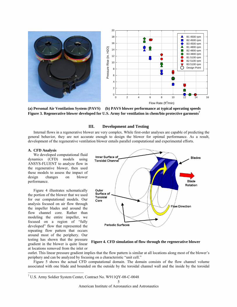
space suit ventilation. The U.S. Army Soldier System Center has sponsored development of a Personal Air Ventilation System (PAVS) with the goal of relieving heat stress for soldiers wearing chem/bio protective gear in hot environments. The PAVS draws air through activated carbon filters and then forces the clean air through the garments, providing a ventilating flow through the protective garment that can significantly reduce heat stress. Figure 3a shows a photograph of a PAVS, which comprises a dual regenerative blower, two C2-A1 filters, and a battery pack. Figure 3b shows typical performance data at rotating speeds of 4500, 4800, and 5100 rpm. At the design point of 10 ft3/min, the regenerative PAVS produces a pressure rise of 5 in. H2O. The flow rates and large pressure losses needed to force ventilating air through filters and protective garments are very similar to the requirements for the space suit ventilation fan. The performance of the PAVS prototype shows that a regenerative blower can produce flows that are suitable for space suit ventilation while operating at low speed.
American Institute of Aeronautics and Astronautics
5
III. Development and Testing Internal flows in a regenerative blower are very complex. While first-order analyses are capable of predicting the
general behavior, they are not accurate enough to design the blower for optimal performance. As a result, development of the regenerative ventilation blower entails parallel computational and experimental efforts.
A. CFD Analysis We developed computational fluid
dynamics (CFD) models using ANSYS-FLUENT to analyze flow in the regenerative blower, then used these models to assess the impact of design changes on blower performance.
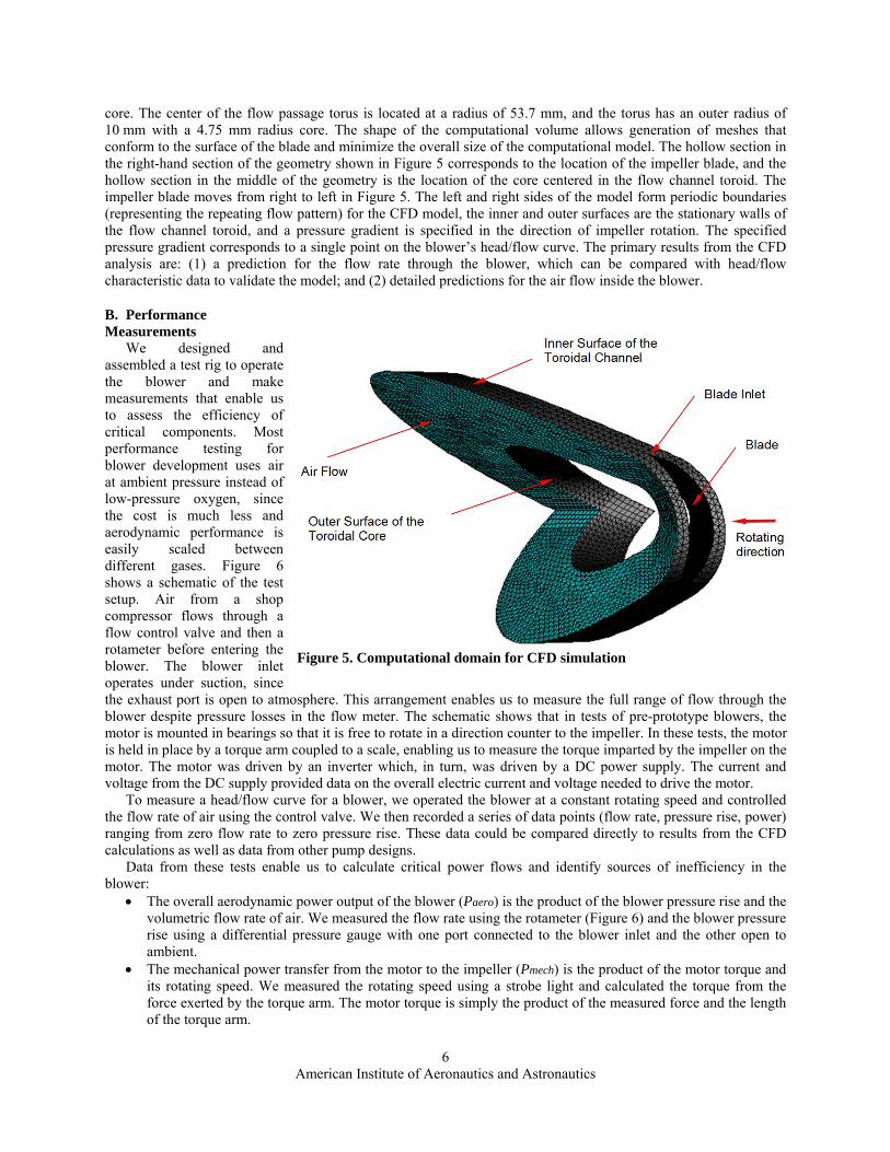
Figure 4 illustrates schematically the portion of the blower that we used for our computational models. Our analysis focused on air flow through the impeller blades and around the flow channel core. Rather than modeling the entire impeller, we focused on a region of “fully developed” flow that represented the repeating flow pattern that occurs around most of the periphery. Our testing has shown that the pressure gradient in the blower is quite linear at locations removed from the inlet or outlet. This linear pressure gradient implies that the flow pattern is similar at all locations along most of the blower’s periphery and can be analyzed by focusing on a characteristic “unit cell.”
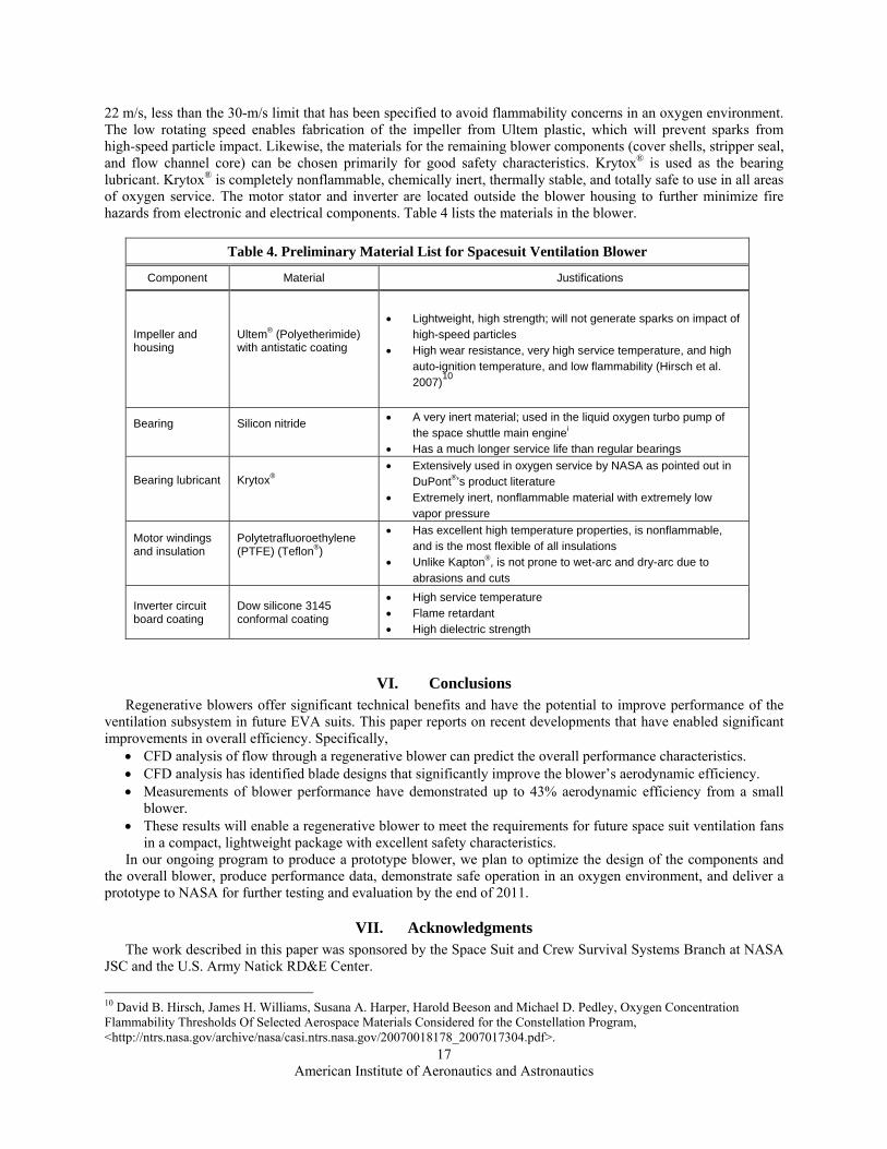
Figure 5 shows the actual CFD computational domain. The domain consists of the flow channel volume associated with one blade and bounded on the outside by the toroidal channel wall and the inside by the toroidal
7 U.S. Army Soldier System Center, Contract No. W911QY-08-C-0048
(a) Personal Air Ventilation System (PAVS) (b) PAVS blower performance at typical operating speeds Figure 3. Regenerative blower developed for U.S. Army for ventilation in chem/bio protective garments7
Figure 4. CFD simulation of flow through the regenerative blower
Flow Rate (ft3/min)
0 2 4 6 8 10 12 14 16
Pre
ssu
re R
ise
(in.
H2
O)
0
2
4
6
8
10
12
14
16
18
20
B1 4500 rpmB2 4500 rpmB3 4500 rpmB1 4800 rpm B2 4800 rpmB3 4800 rpmB1 5100 rpm B2 5100 rpm B3 5100 rpm Design Point
American Institute of Aeronautics and Astronautics
6
core. The center of the flow passage torus is located at a radius of 53.7 mm, and the torus has an outer radius of 10 mm with a 4.75 mm radius core. The shape of the computational volume allows generation of meshes that conform to the surface of the blade and minimize the overall size of the computational model. The hollow section in the right-hand section of the geometry shown in Figure 5 corresponds to the location of the impeller blade, and the hollow section in the middle of the geometry is the location of the core centered in the flow channel toroid. The impeller blade moves from right to left in Figure 5. The left and right sides of the model form periodic boundaries (representing the repeating flow pattern) for the CFD model, the inner and outer surfaces are the stationary walls of the flow channel toroid, and a pressure gradient is specified in the direction of impeller rotation. The specified pressure gradient corresponds to a single point on the blower’s head/flow curve. The primary results from the CFD analysis are: (1) a prediction for the flow rate through the blower, which can be compared with head/flow characteristic data to validate the model; and (2) detailed predictions for the air flow inside the blower.
B. Performance Measurements
We designed and assembled a test rig to operate the blower and make measurements that enable us to assess the efficiency of critical components. Most performance testing for blower development uses air at ambient pressure instead of low-pressure oxygen, since the cost is much less and aerodynamic performance is easily scaled between different gases. Figure 6 shows a schematic of the test setup. Air from a shop compressor flows through a flow control valve and then a rotameter before entering the blower. The blower inlet operates under suction, since the exhaust port is open to atmosphere. This arrangement enables us to measure the full range of flow through the blower despite pressure losses in the flow meter. The schematic shows that in tests of pre-prototype blowers, the motor is mounted in bearings so that it is free to rotate in a direction counter to the impeller. In these tests, the motor is held in place by a torque arm coupled to a scale, enabling us to measure the torque imparted by the impeller on the motor. The motor was driven by an inverter which, in turn, was driven by a DC power supply. The current and voltage from the DC supply provided data on the overall electric current and voltage needed to drive the motor.
To measure a head/flow curve for a blower, we operated the blower at a constant rotating speed and controlled the flow rate of air using the control valve. We then recorded a series of data points (flow rate, pressure rise, power) ranging from zero flow rate to zero pressure rise. These data could be compared directly to results from the CFD calculations as well as data from other pump designs.
Data from these tests enable us to calculate critical power flows and identify sources of inefficiency in the blower:
The overall aerodynamic power output of the blower (Paero) is the product of the blower pressure rise and the volumetric flow rate of air. We measured the flow rate using the rotameter (Figure 6) and the blower pressure rise using a differential pressure gauge with one port connected to the blower inlet and the other open to ambient.
The mechanical power transfer from the motor to the impeller (Pmech) is the product of the motor torque and its rotating speed. We measured the rotating speed using a strobe light and calculated the torque from the force exerted by the torque arm. The motor torque is simply the product of the measured force and the length of the torque arm.
Figure 5. Computational domain for CFD simulation

American Institute of Aeronautics and Astronautics
7
The electrical power input to the blower (Pin) is the product of the input current and voltage. The ratios of these power measurements indicate how efficiently the blower can convert the input electric power to output aerodynamic power. For example, the motor efficiency is the ratio of input electric power to output mechanical power (Pmech/Pin). The blower’s mechanical efficiency is the ratio of aero power output to mechanical power input (Paero/Pmech).
IV. Analysis and Test Results The results of our CFD analysis show both important details of the internal flow structure and can be used to
compute the overall head/flow performance and efficiency of the blower. These data in turn can be compared with results of blower tests to validate the models and demonstrate possible improvements. We have found that our CFD model is capable of predicting head/flow performance within 10%. We have used CFD successfully to assess the effects of impeller design changes and identify a design that optimizes the blower’s aerodynamic efficiency.
A. CFD Analysis Results Figure 7, Figure 8, and Figure 9 show typical, detailed results from the CFD analysis. The simulation conditions
correspond to air at atmospheric pressure with the impeller rotating at 4600 rpm. In Figure 7 and Figure 8, the blade is located on the left and is moving into the page. These results show that the flow rotates counterclockwise around the torus core. The flow passes downward through the impeller blades, which accelerate the flow so that the air leaving the blade passage has the highest velocity magnitude. The flow simulation results suggest a strong flow separation in the toroidal direction when the blower pressure rise is significantly higher than the design value of 5 in. H2O (Figure 9). Flow separation in the poloidal direction persists under all the flow conditions (Figure 9).8
8 The toroidal direction is the direction of impeller rotation. The poloidal direction is perpendicular to the toroidal direction, represented by circles that surround the flow channel core.
P T
ShopAir
FlowControl
Rotameter
Blower
P
DC Power Supply
1.234 1.234
Current Voltage
Torque Arm
Motor
Bearings
Exhaust
Inverter
Figure 6. Test facility to measure blower performance at atmospheric pressure

American Institute of Aeronautics and Astronautics
8
Figure 7. Velocity magnitude contours on the CFD model periodic boundaries
Figure 8. Velocity vectors on the CFD model periodic boundaries

American Institute of Aeronautics and Astronautics
9
Figure 9. Variation in velocity fields as a function of imposed pressure gradient. The coarse scale (right-hand red/yellow plots) shows forward vs. backwards flow regions.
Figure 10 shows stream traces for the flow in three different locations in the blower for three different imposed
pressure gradients. The stream traces in the figure are constructed by assembling results from multiple computational domains in series and highlighting a single stream trace as it passes from one domain to the next. The flow in the figure is highlighted by three stream traces, one starting near the root of the blade (red), one near the middle (green), and one near the tip (blue). The figure presents results for three levels of overall blower pressure rise: 2.5, 5.0, and 10 in. H2O. For each of these specified levels of pressure rise, the figure shows the stream traces as viewed from the side (i.e., looking parallel to the axis of the impeller) and from end-on (i.e., along the axis of the flow channel core).
The CFD results illustrate some key features of flow through the regenerative blower: 1. The overall flow pattern is consistent with the basic concept of how a regenerative blower works. The
impeller blades impart momentum to the air that propels it upstream before reentering the blade row. The air follows a spiral path through and around the flow channel core that becomes more tightly wound as the pressure gradient increases.
2. The flow is highly three-dimensional. The distance that the air travels upstream before reentering the blades depends strongly on its starting position. The calculations indicate very different behavior for the stream traces depending on whether they start at the blade root, the blade tip, or in between.
3. Pressure gradients strongly affect the flow pattern. Higher pressure gradients make it more difficult for the air to flow upstream and cause the air to reenter the blades after traveling a shorter path in the direction of blade-row rotation. The path of air propelled by the tips of the impeller blades (nearest the toroid core) is more sensitive to the pressure gradient than the path of air propelled by the blade roots. At low pressure gradients, the air near the blade tip travels furthest upstream. At higher pressure gradients, however, air propelled by the blade tips moves the shortest distance upstream.
4. The CFD results also show significant flow separation near the annular core as flow leaves the blades and makes a sharp turn around the core. This flow separation reduces the effective cross-sectional area for flow and introduces additional mixing losses. Both effects reduce the blower flow rate and efficiency. Flow separation due to the sharp turn around the core is not unexpected.
5 in H2O
10 in H2O
2.5 in H2O
Toroidal Velocity (m/s) Poloidal Velocity (m/s)

American Institute of Aeronautics and Astronautics
10
Overall P (in. H2O)
Stream Traces – Side View Stream Traces – End View
2.5
5.0
10.0
Figure 10. Calculated stream traces in the regenerative blower
B. Comparison of CFD Results With Blower Performance Data We used the CFD analyses and detailed measurements of blower performance to improve the design of the
blower. A key finding was that CFD analysis could successfully guide the blower design. Specifically, CFD was able to predict how blade design affected the aerodynamic efficiency of the blower.
We examined three blade designs: a baseline design that was used in the proof-of-concept blower described in our prior paper, and two variants denoted blade 2 and blade 3. These blades are all similar in size and pitch, but differ in features of their shape that affect the gas velocity distribution at the blade exit. Blade 2 was designed to increase the gas velocity at the blade exit relative to the baseline blade design, and blade 3 was designed to decrease the gas velocity relative to the baseline. We evaluated a wide range of mesh resolutions and several of the available turbulence models to compare the solution results. We have found that the CFD results are sensitive to both the grid resolutions and the turbulence model. As a result, we expected that direct comparisons of the CFD simulations to experimental data would be difficult. However, the CFD results should still be useful. Comparison of CFD results from simulations of the three blade designs should still enable us to draw conclusions that would guide changes in design to improve performance and assessment of experimental data.
Figure 11 shows the predicted aerodynamic efficiency as a function of flow rate for the three blade designs based on the CFD simulations. The aerodynamic efficiency is defined as follows:
Flow Separation

American Institute of Aeronautics and Astronautics
11
T
pVaero
(1)
The simulation conditions correspond to air at atmospheric pressure with the impeller rotating at 4600 rpm. We ran simulations for a range of imposed pressure rise from the inlet to the outlet of the blower to generate performance curves. The simulation and experimental data for the baseline blade design are in relatively good agreement, with a peak efficiency around 37 to 38% at flow rates in the range 5.0 to 5.5 ft3/min. The simulations show a slightly higher efficiency at higher flow rates than the experimental results.
The results in Figure 11 also show the dramatically different predicted performance for the blades 2 and 3. For blade 2, the predicted efficiency is about eight percentage points higher than the baseline blade and occurs at a higher flow rate. For blade 3, the predicted performance is slightly worse than the symmetric blade design. Increasing the blade spacing (pitch) by 30% (and reducing the number of blades accordingly) is predicted to offer a slight improvement in efficiency.
0
0.1
0.2
0.3
0.4
0.5
0 1 2 3 4 5 6 7 8
Original Blade Design (experiment)
Original Blade Design (CFD)
Blade Design 2 (CFD)
Blade Design 3 (CFD)
Ae
rod
ynam
ic E
ffici
ency
Flow (CFM)
Figure 11. Aerodynamic efficiency for three blade designs We fabricated impellers based on blade designs 2 and 3 and confirmed by test that the CFD analyses correctly
predicted the efficiency trend. Figure 12 shows that the blower with blade 2 generates a much higher pressure rise than the other two designs. As discussed in the next section, the aerodynamic efficiency of the impeller with blade design 2 achieves maximum aero efficiencies greater than 40% over rotating speeds ranging from 3200 to 6000 rpm. For the nominal ventilation flow rate, maximum efficiency was achieved by rotating the impeller at speeds in the range 4000 to 4500 rpm. Figure 13 compares the measured and predicted efficiency of the impeller with forward-tilted blades. The CFD results are in reasonably good agreement with the experimental data, predicting correctly: (1) the optimal impeller design, (2) the flow rate for maximum efficiency, and (3) the aerodynamic efficiency achieved at the optimal flow rate.

American Institute of Aeronautics and Astronautics
12
0
2
4
6
8
10
12
14
16
18
0 2 4 6 8 10 12 14Flow Rate (CFM)
Pre
ssur
e R
ise
(in.
H2 O
)
Original blades
Blade Design 2
Blade Design 3
5/13/2010
Simple Stripper Seal4590 rpm
Figure 12. Head/flow performance of regenerative blower with modified impeller designs
Figure 13. Actual and predicted blower efficiency (blade design 2, 4600 rpm)
To compare the overall flow patterns predicted by CFD with the performance of the actual blower, we injected a
small amount of chalk dust into the blower while it was operating. The dust would follow the general flow path of gas through the blower and leave traces on the blower housing that could be compared with the CFD results. After a chalk dust test, we disassembled the blower to observe the chalk dust pattern and compare with the CFD results. Although this approach could not provide detailed information on the velocity distribution, it was easy to measure the overall pitch of the spiral flow path of gas through the blower. We found that the measured spiral pitch agreed with the CFD predictions to within 15%.
0
0.1
0.2
0.3
0.4
0.5
0 1 2 3 4 5 6 7 8
CFD Prediction
Experiment
Ae
rody
nam
ic E
ffici
ency
Flow (CFM)

American Institute of Aeronautics and Astronautics
13
C. Blower Aerodynamic Efficiency Measurements After identifying the optimal blade design (blade design 2) for the regenerative blower, we produced detailed
performance maps by measuring the blower performance for rotating speeds ranging from 3200 to 6000 rpm. These tests were conducted using air at atmospheric pressure in our benchtop test rig (Figure 6) to enable direct measurement of the blower’s aero efficiency. Figure 14 shows head/flow performance curves for the blower with blade design 2 at five rotating speeds, with flow rates up to 10 ft3/min and pressure rises that exceed 15 in. H2O. The data in the plot have been reduced to the dimensionless head coefficient () and flow coefficient ():
UAN
V
U
p
221
(2)
In dimensionless form, all the data fall on essentially the same curve, showing that the measurements are consistent from test to test and that conventional turbomachine scaling applies to the regenerative blower.
Also plotted in the figure is the design point for the ventilation fan (scaled to standard pressure9). The point shown on the plot was calculated assuming a rotating speed of 4300 rpm. The operating point lies on the measured head/flow curves, and shows that the blower will meet the nominal head/flow requirements while rotating at 4300 rpm.
Figure 14. Head/flow performance of regenerative blower with blade design 2
We also measured the blower’s aerodynamic efficiency at each of the test points shown in Figure 14. The
efficiency of the blower with the most efficient blade design (#2) is plotted in Figure 15 as a function of volumetric flow rate and rotating speed. At a rotating speed of 4590 rpm, the peak efficiency of 41% is achieved at a flow coefficient of 0.53, which corresponds to the specified operating point of the blower (5 ft3/min). At this efficiency, the mechanical power required by the impeller is only 3.7 W. These data show that the analysis and test program has 9 Corresponding operating points are found using standard scaling laws for turbomachines and incompressible fluids. To relate tests at standard conditions to operation in a space suit, the blower must achieve the specified volumetric flow at the specified rotating speed with a pressure rise that is directly proportional to gas density. Therefore the required pressure rise in the benchtop test apparatus is (14.7 psia/4.3 psia) = 3.4 times larger than the 2.7 in. H2O specified for the ventilation fan at low pressure, 3.4 2.7 = 9.2 in. H2O, as shown in Figure 14.

American Institute of Aeronautics and Astronautics
14
successfully produced a blower that achieves a high, maximum aerodynamic efficiency at the desired operating point.
Figure 15. Aero efficiency of regenerative blower with blade design 2 These data show significant improvement compared to the performance of the proof-of-concept blower
described in our earlier paper. The earlier blower met the baseline ventilation flow requirements at a rotating speed of 5400 rpm, consuming 9 W of electric power. The current prototype can achieve buddy mode flow requirements by operating at a speed of 7800 rpm and consuming 17 W of shaft power. The earlier prototype would have needed to rotate at 9800 rpm to achieve the buddy mode head/flow requirements.
V. Prototype Blower Design
We have completed the mechanical design of the impeller and blower housing and have fabricated components in preparation for detailed performance measurements. Table 2 lists the main design features of the current prototype design. The design goal is to provide optimal performance for the nominal flow conditions (4.7 ft3/min and 2.7 in. H2O) with the capability of short, infrequent operation under buddy mode when necessary. Normal rotating speed is 4300 rpm with a power consumption of 6.9 W. Figure 16 shows the impeller and the outer housing of the blower. The overall diameter of the blower is 5.6 in. The blower height is 1.4 in. at the center and 1.3 in. at the circumference.

American Institute of Aeronautics and Astronautics
15
Figure 16. Ultem impeller and housing
A. Analysis of Efficiency and Power Consumption The blade and flow passage design of the prototype are the same as prior test blowers, so we are confident that
the aero efficiency of the prototype will match our prior test data. The compact motor is still under development, and predictions of overall efficiency rely on projected mechanical and electrical losses. Based on the parasitic losses of different components determined from separate effects tests, we estimated the DC power input for the blower. The expected blower power input is about 7 W under the baseline design conditions and overall blower efficiency is about 22%. The blower power input will be about 2 W lower than the proof-of-concept blower reported previously. The main losses in the system include flow losses, bearing and drag losses, and motor losses.
Table 2. Preliminary Design and Predicted Performance of the Regenerative Ventilation Blower
Performance Operating mode Normal operation Flow rate (actual ft3/min) 4.7 Pressure rise (in. H2O) 2.7 Rotating speed (rpm) 4300 Power consumption (W) 6.9 Design Impeller material Ultem Flow passage material Ultem Impeller diameter at blade root (in.) 3.5
Bearings Silicon nitride hybrid bearing
Bearing lubricant Krytox® Pressure boost per stage (in. H2O) 0.72 Mass Breakdown Impeller (g) 61 Housing and flow passages (g) 316 Inlet/outlet assembly (g) 45 Bearings (g) 3 Motor and controller (g) 195 Auxiliary components (g) 60 TOTAL (g) 680

American Institute of Aeronautics and Astronautics
16
B. Mechanical Design and Fabrication The blower impeller and housings are made of Ultem thermoplastic. We selected Ultem for its high mechanical
strength and high auto-ignition temperature. The impeller was fabricated by 5-axis CNC milling, then bonded to the rotor of an outrunner Brushless DC Permanent Magnet motor. The motor stator is separated from the ventilation gas by a thin wall that is an integral part of the blower cover (Figure 17). The impeller is supported by the outer races of two hybrid ceramic ball bearings. The inner races of the bearings are, in turn, supported by a stationary shaft connected to the housing. The shaft also supports the housing covers to reduce deflection due to internal pressure when operating in a vacuum. Housing deflection and mechanical stresses under expected differential pressures were estimated with ANASYS® software. The results from structural analyses confirm that there will be no mechanical interference due to the housing deflection and the maximum stresses in the housing are well below the material yield strength.
Figure 17. Cross-section/exploded view of ventilation blower design model
C. Cooling The heat generated in the motor stator flows by conduction to an aluminum plate bonded to it. The aluminum
plate will be cooled either by the ventilation flow or by other heat sinks available in the PLSS. The total heat dissipated from the stator is about 1 W. The motor inverter will dissipate about 0.4 W of heat and also needs to be actively cooled. However, the small inverter can be located remotely from the blower at locations where cooling is readily available.
D. Safety Features The regenerative blower will improve overall safety, due primarily to its low rotating speed and the oxygen-safe
materials that can be used thanks to the low rotating speed. At 4300 rpm, the tip speed of the impeller is only about
Table 3. Analysis of Power Consumption
Proof-of-Concept Projected Prototype Power Consumption Aero power (W) 1.5 1.5 Flow losses (W) 3 2.5 Bearing and impeller drag losses (W) 3 1.5 Motor losses (W) 1 1.0 Inverter losses (W) 0.5 0.4 TOTAL power input (W) 9 6.9 Aero efficiency 0.33 0.4 Motor efficiency 0.88 0.85 Inverter efficiency 0.94 0.94 Overall efficiency 0.17 0.22
American Institute of Aeronautics and Astronautics
17
22 m/s, less than the 30-m/s limit that has been specified to avoid flammability concerns in an oxygen environment. The low rotating speed enables fabrication of the impeller from Ultem plastic, which will prevent sparks from high-speed particle impact. Likewise, the materials for the remaining blower components (cover shells, stripper seal, and flow channel core) can be chosen primarily for good safety characteristics. Krytox® is used as the bearing lubricant. Krytox® is completely nonflammable, chemically inert, thermally stable, and totally safe to use in all areas of oxygen service. The motor stator and inverter are located outside the blower housing to further minimize fire hazards from electronic and electrical components. Table 4 lists the materials in the blower.
Table 4. Preliminary Material List for Spacesuit Ventilation Blower
Component Material Justifications
Impeller and housing
Ultem® (Polyetherimide) with antistatic coating
Lightweight, high strength; will not generate sparks on impact of high-speed particles
High wear resistance, very high service temperature, and high auto-ignition temperature, and low flammability (Hirsch et al. 2007)
10
Bearing Silicon nitride A very inert material; used in the liquid oxygen turbo pump of the space shuttle main enginei
Has a much longer service life than regular bearings
Bearing lubricant Krytox® Extensively used in oxygen service by NASA as pointed out in
DuPont®’s product literature Extremely inert, nonflammable material with extremely low
vapor pressure
Motor windings and insulation
Polytetrafluoroethylene (PTFE) (Teflon®)
Has excellent high temperature properties, is nonflammable, and is the most flexible of all insulations
Unlike Kapton®, is not prone to wet-arc and dry-arc due to abrasions and cuts
Inverter circuit board coating
Dow silicone 3145 conformal coating
High service temperature Flame retardant High dielectric strength
VI. Conclusions Regenerative blowers offer significant technical benefits and have the potential to improve performance of the
ventilation subsystem in future EVA suits. This paper reports on recent developments that have enabled significant improvements in overall efficiency. Specifically,
CFD analysis of flow through a regenerative blower can predict the overall performance characteristics. CFD analysis has identified blade designs that significantly improve the blower’s aerodynamic efficiency. Measurements of blower performance have demonstrated up to 43% aerodynamic efficiency from a small
blower. These results will enable a regenerative blower to meet the requirements for future space suit ventilation fans
in a compact, lightweight package with excellent safety characteristics. In our ongoing program to produce a prototype blower, we plan to optimize the design of the components and
the overall blower, produce performance data, demonstrate safe operation in an oxygen environment, and deliver a prototype to NASA for further testing and evaluation by the end of 2011.
VII. Acknowledgments The work described in this paper was sponsored by the Space Suit and Crew Survival Systems Branch at NASA
JSC and the U.S. Army Natick RD&E Center.
10 David B. Hirsch, James H. Williams, Susana A. Harper, Harold Beeson and Michael D. Pedley, Oxygen Concentration Flammability Thresholds Of Selected Aerospace Materials Considered for the Constellation Program, <http://ntrs.nasa.gov/archive/nasa/casi.ntrs.nasa.gov/20070018178_2007017304.pdf>.

American Institute of Aeronautics and Astronautics
18
VIX. References 3Barnes, B., Conger, B., Leavitt, G., Autrey, D. and Wells, J., “Constellation Space Suit Element PLSS Baseline Schematics
and Internal Interfaces,” Rev. B, CTSD-CX-5117, JSC-65563, NASA/Johnson Space Center, September 2009. 4CRAVE DO-39 PLSS Fan Assembly Development for Exploration Technology, Contract No. NNJ05HB39B, Fan Assembly
Concept and Design Report, Hamilton Sundstrand, Final Report. 5Kempf, R., Vogel, M. and Paul, H., “Ventilation Transport Trade Study for Future Space Suit Life Support Systems,” 38th
International Conference on Life Support Systems, SAE International, Paper No. 2008-01-2115, June 29–July 2, 2008. 6Paul, H., Jennings, M. and Vogel, M., “Fan Performance Testing and Oxygen Compatibility Assessment Results for Future
Space Suit Life Support Systems,” 2009 International Conference on Environmental Systems, SAE International, Paper No. 2009-01-2448, July 2009.
7Balje, O. E., Turbomachines: A Guide to Design, Selection, and Theory, John Wiley & Sons, Inc.: New York, 1981. 8Sixsmith, H. and Altmann, H., “A Regenerative Compressor,” Vol. 99, No. 3, J Eng Ind., ASME Trans., 1977, pp. 637–647. 9Swift, W. L., Nutt, W. E. and Sixsmith, H., “A Helium Regenerative Compressor,” Advances in Cryogenic Engineering,
(Albuquerque, NM), edited by P. Kittel, Vol. 39A, Plenum Press, New York, NY, 1994, pp. 901–908. 10Kline-Schoder, R. J. and Sorensen, P. H., “Miniature High Vacuum Pumps for Analytical Instruments,” Presented at: 6th
Harsh-Environment Mass Spectrometry Workshop, Coco Beach, FL, 17–20 Sep 2007.
X. Contact Dr. Michael G. Izenson is a Principal Engineer at Creare Inc., where he has developed innovative thermal
technologies for over 20 years. E-mail address: [email protected].
XI. Acronyms CFD: computational fluid dynamics CFM: ft3/min CO2: carbon dioxide CSSE: Constellation Space Suit Element CSSS: Constellation Space Suit System DN: bearing diameter rotating speed EVA: extravehicular activity JSC: Johnson Space Center LCVG: liquid cooling and ventilation garment PLSS: Portable Life Support System PTFE: polytetrafluoroethylene (Teflon®) rpm: revolutions/min i <http://www.nasa.gov/offices/oce/llis/0890.html>