series 1 ink jet system operations manual, 5802657 … · diagraph, an itw company section 1:...
TRANSCRIPT
OperationsManual
1 Missouri Research Park Drive • St. Charles, MO 63304 • 1-800-521-3047 • ServiceLine 1-800-526-2531Illinois Tool Works Inc © 2002
5802-657
Series 1Ink Jet System
Revision E

Diagraph, an ITW Company Table of Contents
5802-657 Operations Manual Rev E
Section 1: Introduction . . . . . . . . . . . . . . . . . . . . . . . . . . . . . . . . . . . . . . . . . . . . . . . . . . . . . . . . . . . .1
Section 2: Safety . . . . . . . . . . . . . . . . . . . . . . . . . . . . . . . . . . . . . . . . . . . . . . . . . . . . . . . . . . . . . . . . . .3
Section 3: System Components . . . . . . . . . . . . . . . . . . . . . . . . . . . . . . . . . . . . . . . . . . . . . . . . . . . . . .53.1 Series 1 Controller . . . . . . . . . . . . . . . . . . . . . . . . . . . . . . . . . . . . . . . . . . . . . . . . . . . . . . . . 53.2 Bracketry . . . . . . . . . . . . . . . . . . . . . . . . . . . . . . . . . . . . . . . . . . . . . . . . . . . . . . . . . . . . . . . 63.3 Printheads . . . . . . . . . . . . . . . . . . . . . . . . . . . . . . . . . . . . . . . . . . . . . . . . . . . . . . . . . . . . . . 73.4 Ink Regulator . . . . . . . . . . . . . . . . . . . . . . . . . . . . . . . . . . . . . . . . . . . . . . . . . . . . . . . . . . . . 83.5 Photosensor . . . . . . . . . . . . . . . . . . . . . . . . . . . . . . . . . . . . . . . . . . . . . . . . . . . . . . . . . . . . . 93.6 Encoder . . . . . . . . . . . . . . . . . . . . . . . . . . . . . . . . . . . . . . . . . . . . . . . . . . . . . . . . . . . . . . . . 93.7 PC Software (PC-Based Systems Only) . . . . . . . . . . . . . . . . . . . . . . . . . . . . . . . . . . . . . . . 93.8 LC/400 Hand-Held Terminal (Stand-Alone Systems Only) . . . . . . . . . . . . . . . . . . . . . . . 10
Section 4: Getting Started . . . . . . . . . . . . . . . . . . . . . . . . . . . . . . . . . . . . . . . . . . . . . . . . . . . . . . . . .11
Section 5: Installation . . . . . . . . . . . . . . . . . . . . . . . . . . . . . . . . . . . . . . . . . . . . . . . . . . . . . . . . . . . .155.1 Components ID . . . . . . . . . . . . . . . . . . . . . . . . . . . . . . . . . . . . . . . . . . . . . . . . . . . . . . . . . 155.2 Testing the Electrical Outlet . . . . . . . . . . . . . . . . . . . . . . . . . . . . . . . . . . . . . . . . . . . . . . . 15
Electrical Line Transients . . . . . . . . . . . . . . . . . . . . . . . . . . . . . . . . . . . . . . . . . . . . . . 155.3 Materials Required for Installation . . . . . . . . . . . . . . . . . . . . . . . . . . . . . . . . . . . . . . . . . . 165.4 Installing Bracketry . . . . . . . . . . . . . . . . . . . . . . . . . . . . . . . . . . . . . . . . . . . . . . . . . . . . . . 165.5 Mounting Printheads . . . . . . . . . . . . . . . . . . . . . . . . . . . . . . . . . . . . . . . . . . . . . . . . . . . . . 175.6 Mounting Photosensor Bracketry (5700-435) . . . . . . . . . . . . . . . . . . . . . . . . . . . . . . . . . . 175.7 Mounting the Photosensor . . . . . . . . . . . . . . . . . . . . . . . . . . . . . . . . . . . . . . . . . . . . . . . . . 175.8 Photosensor Sensitivity Adjustment . . . . . . . . . . . . . . . . . . . . . . . . . . . . . . . . . . . . . . . . . 185.9 The Encoder . . . . . . . . . . . . . . . . . . . . . . . . . . . . . . . . . . . . . . . . . . . . . . . . . . . . . . . . . . . . 185.10 Setting Up the Stand/Shelf Assembly . . . . . . . . . . . . . . . . . . . . . . . . . . . . . . . . . . . . . . . 195.11 Controller Connections . . . . . . . . . . . . . . . . . . . . . . . . . . . . . . . . . . . . . . . . . . . . . . . . . . 19
Removing the Cover . . . . . . . . . . . . . . . . . . . . . . . . . . . . . . . . . . . . . . . . . . . . . . . . . . 19Cable Connections . . . . . . . . . . . . . . . . . . . . . . . . . . . . . . . . . . . . . . . . . . . . . . . . . . . . 20Securing Loose Cable . . . . . . . . . . . . . . . . . . . . . . . . . . . . . . . . . . . . . . . . . . . . . . . . . 20Interface Board Settings . . . . . . . . . . . . . . . . . . . . . . . . . . . . . . . . . . . . . . . . . . . . . . . 21Setting DIP Switches on the Logic Boards . . . . . . . . . . . . . . . . . . . . . . . . . . . . . . . . . 25Setting Printhead Addresses . . . . . . . . . . . . . . . . . . . . . . . . . . . . . . . . . . . . . . . . . . . . 26Setting the Fixed Speed Reporter . . . . . . . . . . . . . . . . . . . . . . . . . . . . . . . . . . . . . . . . 27Calculating the Print Indentation . . . . . . . . . . . . . . . . . . . . . . . . . . . . . . . . . . . . . . . . . 27Setting the Indentation for SA99 and PC-Based Systems . . . . . . . . . . . . . . . . . . . . . . 27Selecting Indentation for the SA99 Message Select . . . . . . . . . . . . . . . . . . . . . . . . . . 28Continuous Printing (SA99 or PC System) . . . . . . . . . . . . . . . . . . . . . . . . . . . . . . . . . 28
5.12 Configuring the IDS . . . . . . . . . . . . . . . . . . . . . . . . . . . . . . . . . . . . . . . . . . . . . . . . . . . . 29Ink Line Connections . . . . . . . . . . . . . . . . . . . . . . . . . . . . . . . . . . . . . . . . . . . . . . . . . 29Attaching Ink Regulators . . . . . . . . . . . . . . . . . . . . . . . . . . . . . . . . . . . . . . . . . . . . . . . 30Plumbing the System . . . . . . . . . . . . . . . . . . . . . . . . . . . . . . . . . . . . . . . . . . . . . . . . . . 30Connecting the Printheads . . . . . . . . . . . . . . . . . . . . . . . . . . . . . . . . . . . . . . . . . . . . . . 30Connecting the Beacon to the IDS . . . . . . . . . . . . . . . . . . . . . . . . . . . . . . . . . . . . . . . 31Connecting the Ink Supply . . . . . . . . . . . . . . . . . . . . . . . . . . . . . . . . . . . . . . . . . . . . . 31Connecting Power to the Controller/IDS . . . . . . . . . . . . . . . . . . . . . . . . . . . . . . . . . . 31Priming . . . . . . . . . . . . . . . . . . . . . . . . . . . . . . . . . . . . . . . . . . . . . . . . . . . . . . . . . . . . 31Checking Ink Pressure . . . . . . . . . . . . . . . . . . . . . . . . . . . . . . . . . . . . . . . . . . . . . . . . . 32
Diagraph, an ITW Company Table of Contents
5802-657 Operations Manual Rev E
Setting Ink Pressure . . . . . . . . . . . . . . . . . . . . . . . . . . . . . . . . . . . . . . . . . . . . . . . . . . . 33Final Installation Checklist . . . . . . . . . . . . . . . . . . . . . . . . . . . . . . . . . . . . . . . . . . . . . 35
Section 6: LC/400 Hand-Held Terminal . . . . . . . . . . . . . . . . . . . . . . . . . . . . . . . . . . . . . . . . . . . . .396.1 LC/400 Keypad . . . . . . . . . . . . . . . . . . . . . . . . . . . . . . . . . . . . . . . . . . . . . . . . . . . . . . . . . 39
Substitute LCD Characters . . . . . . . . . . . . . . . . . . . . . . . . . . . . . . . . . . . . . . . . . . . . . 39Function Keys . . . . . . . . . . . . . . . . . . . . . . . . . . . . . . . . . . . . . . . . . . . . . . . . . . . . . . . 39Shift Functions . . . . . . . . . . . . . . . . . . . . . . . . . . . . . . . . . . . . . . . . . . . . . . . . . . . . . . . 40
6.2 LC/400 Menu Options . . . . . . . . . . . . . . . . . . . . . . . . . . . . . . . . . . . . . . . . . . . . . . . . . . . . 406.3 Selecting a Printhead . . . . . . . . . . . . . . . . . . . . . . . . . . . . . . . . . . . . . . . . . . . . . . . . . . . . . 416.4 Selecting a Message to Print . . . . . . . . . . . . . . . . . . . . . . . . . . . . . . . . . . . . . . . . . . . . . . . 416.5 Writing and Saving a Message . . . . . . . . . . . . . . . . . . . . . . . . . . . . . . . . . . . . . . . . . . . . . 41
Changing Factory Defaults . . . . . . . . . . . . . . . . . . . . . . . . . . . . . . . . . . . . . . . . . . . . . 426.6 Editing a Message . . . . . . . . . . . . . . . . . . . . . . . . . . . . . . . . . . . . . . . . . . . . . . . . . . . . . . . 426.7 Autocodes . . . . . . . . . . . . . . . . . . . . . . . . . . . . . . . . . . . . . . . . . . . . . . . . . . . . . . . . . . . . . 42
Autocode Formats . . . . . . . . . . . . . . . . . . . . . . . . . . . . . . . . . . . . . . . . . . . . . . . . . . . . 42Using the Number Sequence Code . . . . . . . . . . . . . . . . . . . . . . . . . . . . . . . . . . . . . . . 43Creating an Upper Limit Sequence . . . . . . . . . . . . . . . . . . . . . . . . . . . . . . . . . . . . . . . 43Using the Pallet Count Code . . . . . . . . . . . . . . . . . . . . . . . . . . . . . . . . . . . . . . . . . . . . 44Font Selection Code (Using 9-dot Fonts) . . . . . . . . . . . . . . . . . . . . . . . . . . . . . . . . . . 44Font Selection Code (Using 18-dot Fonts) . . . . . . . . . . . . . . . . . . . . . . . . . . . . . . . . . 45The Variable Field Prompt . . . . . . . . . . . . . . . . . . . . . . . . . . . . . . . . . . . . . . . . . . . . . 45The Weight Code . . . . . . . . . . . . . . . . . . . . . . . . . . . . . . . . . . . . . . . . . . . . . . . . . . . . . 45Special Expiration Date Code {K} . . . . . . . . . . . . . . . . . . . . . . . . . . . . . . . . . . . . . . . 46
6.8 Checking Printhead Status . . . . . . . . . . . . . . . . . . . . . . . . . . . . . . . . . . . . . . . . . . . . . . . . . 46Status Messages . . . . . . . . . . . . . . . . . . . . . . . . . . . . . . . . . . . . . . . . . . . . . . . . . . . . . . 46
6.9 The Utility Menu . . . . . . . . . . . . . . . . . . . . . . . . . . . . . . . . . . . . . . . . . . . . . . . . . . . . . . . . 47Change Item Number . . . . . . . . . . . . . . . . . . . . . . . . . . . . . . . . . . . . . . . . . . . . . . . . . 47Set Character Width . . . . . . . . . . . . . . . . . . . . . . . . . . . . . . . . . . . . . . . . . . . . . . . . . . 47Set Character Spacing . . . . . . . . . . . . . . . . . . . . . . . . . . . . . . . . . . . . . . . . . . . . . . . . . 48Font Choices . . . . . . . . . . . . . . . . . . . . . . . . . . . . . . . . . . . . . . . . . . . . . . . . . . . . . . . . 48Selecting a Font . . . . . . . . . . . . . . . . . . . . . . . . . . . . . . . . . . . . . . . . . . . . . . . . . . . . . . 49Set Time . . . . . . . . . . . . . . . . . . . . . . . . . . . . . . . . . . . . . . . . . . . . . . . . . . . . . . . . . . . . 49Set Date . . . . . . . . . . . . . . . . . . . . . . . . . . . . . . . . . . . . . . . . . . . . . . . . . . . . . . . . . . . . 49Reset Printhead . . . . . . . . . . . . . . . . . . . . . . . . . . . . . . . . . . . . . . . . . . . . . . . . . . . . . . 49Purge Valves . . . . . . . . . . . . . . . . . . . . . . . . . . . . . . . . . . . . . . . . . . . . . . . . . . . . . . . . 50Change Pallet Count . . . . . . . . . . . . . . . . . . . . . . . . . . . . . . . . . . . . . . . . . . . . . . . . . . 50Set Indentation (SA99 Select System Only) . . . . . . . . . . . . . . . . . . . . . . . . . . . . . . . . 50
6.10 Special Options . . . . . . . . . . . . . . . . . . . . . . . . . . . . . . . . . . . . . . . . . . . . . . . . . . . . . . . . 50European/Canadian Date . . . . . . . . . . . . . . . . . . . . . . . . . . . . . . . . . . . . . . . . . . . . . . . 51One Consecutive Count . . . . . . . . . . . . . . . . . . . . . . . . . . . . . . . . . . . . . . . . . . . . . . . . 51Disable Message Advance . . . . . . . . . . . . . . . . . . . . . . . . . . . . . . . . . . . . . . . . . . . . . . 51Individual Message Counts . . . . . . . . . . . . . . . . . . . . . . . . . . . . . . . . . . . . . . . . . . . . . 51Thumbwheel Message Selection Active . . . . . . . . . . . . . . . . . . . . . . . . . . . . . . . . . . . 51Reset Count to 1 at Power Up or Hardware Reset . . . . . . . . . . . . . . . . . . . . . . . . . . . 52Mirror-Image Print or Lower Half of 1-inch 18-dot Printhead . . . . . . . . . . . . . . . . . . 52Relationship of Special Item Number Options . . . . . . . . . . . . . . . . . . . . . . . . . . . . . . 52Entering the Total Option Value . . . . . . . . . . . . . . . . . . . . . . . . . . . . . . . . . . . . . . . . . 52Determining Which Options Are Already Set . . . . . . . . . . . . . . . . . . . . . . . . . . . . . . . 53

Diagraph, an ITW Company Table of Contents
5802-657 Operations Manual Rev E
Section 7: Maintenance . . . . . . . . . . . . . . . . . . . . . . . . . . . . . . . . . . . . . . . . . . . . . . . . . . . . . . . . . . .557.1 Controller Maintenance . . . . . . . . . . . . . . . . . . . . . . . . . . . . . . . . . . . . . . . . . . . . . . . . . . . 55
Daily Start Up . . . . . . . . . . . . . . . . . . . . . . . . . . . . . . . . . . . . . . . . . . . . . . . . . . . . . . . 55Daily Shutdown . . . . . . . . . . . . . . . . . . . . . . . . . . . . . . . . . . . . . . . . . . . . . . . . . . . . . . 55Intermittent (As Required) . . . . . . . . . . . . . . . . . . . . . . . . . . . . . . . . . . . . . . . . . . . . . 55Annually . . . . . . . . . . . . . . . . . . . . . . . . . . . . . . . . . . . . . . . . . . . . . . . . . . . . . . . . . . . 55
7.2 Printhead Maintenance . . . . . . . . . . . . . . . . . . . . . . . . . . . . . . . . . . . . . . . . . . . . . . . . . . . 55Overnight Shutdown . . . . . . . . . . . . . . . . . . . . . . . . . . . . . . . . . . . . . . . . . . . . . . . . . . 55Overnight Startup . . . . . . . . . . . . . . . . . . . . . . . . . . . . . . . . . . . . . . . . . . . . . . . . . . . . 55Shutdowns of Seven Days or Longer . . . . . . . . . . . . . . . . . . . . . . . . . . . . . . . . . . . . . 56If You Purchased Spare Printheads . . . . . . . . . . . . . . . . . . . . . . . . . . . . . . . . . . . . . . . 56
7.3 Ink Delivery System Maintenance . . . . . . . . . . . . . . . . . . . . . . . . . . . . . . . . . . . . . . . . . . 57Daily Startup . . . . . . . . . . . . . . . . . . . . . . . . . . . . . . . . . . . . . . . . . . . . . . . . . . . . . . . . 57Daily Shutdown . . . . . . . . . . . . . . . . . . . . . . . . . . . . . . . . . . . . . . . . . . . . . . . . . . . . . . 57Intermittent (As Required) . . . . . . . . . . . . . . . . . . . . . . . . . . . . . . . . . . . . . . . . . . . . . 57Annually . . . . . . . . . . . . . . . . . . . . . . . . . . . . . . . . . . . . . . . . . . . . . . . . . . . . . . . . . . . 57General Notes On IDS Maintenance . . . . . . . . . . . . . . . . . . . . . . . . . . . . . . . . . . . . . . 57
7.4 Diagnosis and Repair of Contaminated Ink Delivery Systems . . . . . . . . . . . . . . . . . . . . . 58Ink Regulator Maintenance . . . . . . . . . . . . . . . . . . . . . . . . . . . . . . . . . . . . . . . . . . . . . 58
7.5 Printhead Failure and Flushing . . . . . . . . . . . . . . . . . . . . . . . . . . . . . . . . . . . . . . . . . . . . . 59Preload Adjustment . . . . . . . . . . . . . . . . . . . . . . . . . . . . . . . . . . . . . . . . . . . . . . . . . . . 59Pulse Width Adjustment . . . . . . . . . . . . . . . . . . . . . . . . . . . . . . . . . . . . . . . . . . . . . . . 59Broaching the Orifice . . . . . . . . . . . . . . . . . . . . . . . . . . . . . . . . . . . . . . . . . . . . . . . . . 59
7.6 Changing Ink Containers . . . . . . . . . . . . . . . . . . . . . . . . . . . . . . . . . . . . . . . . . . . . . . . . . . 59
Section 8: Troubleshooting . . . . . . . . . . . . . . . . . . . . . . . . . . . . . . . . . . . . . . . . . . . . . . . . . . . . . . . .618.1 Troubleshooting Notes . . . . . . . . . . . . . . . . . . . . . . . . . . . . . . . . . . . . . . . . . . . . . . . . . . . 61
Interface Board Terminology . . . . . . . . . . . . . . . . . . . . . . . . . . . . . . . . . . . . . . . . . . . 61Logic Board Terminology . . . . . . . . . . . . . . . . . . . . . . . . . . . . . . . . . . . . . . . . . . . . . . 62Self-Diagnostic Test . . . . . . . . . . . . . . . . . . . . . . . . . . . . . . . . . . . . . . . . . . . . . . . . . . 63Normal Operational LED Indications . . . . . . . . . . . . . . . . . . . . . . . . . . . . . . . . . . . . . 63
8.2 Troubleshooting Tests . . . . . . . . . . . . . . . . . . . . . . . . . . . . . . . . . . . . . . . . . . . . . . . . . . . . 63System Operations Test . . . . . . . . . . . . . . . . . . . . . . . . . . . . . . . . . . . . . . . . . . . . . . . . 63Interface Jumper Check . . . . . . . . . . . . . . . . . . . . . . . . . . . . . . . . . . . . . . . . . . . . . . . . 64Logic Board Settings Check . . . . . . . . . . . . . . . . . . . . . . . . . . . . . . . . . . . . . . . . . . . . 64Purge Test . . . . . . . . . . . . . . . . . . . . . . . . . . . . . . . . . . . . . . . . . . . . . . . . . . . . . . . . . . 64Print Test . . . . . . . . . . . . . . . . . . . . . . . . . . . . . . . . . . . . . . . . . . . . . . . . . . . . . . . . . . . 64Photosensor Test . . . . . . . . . . . . . . . . . . . . . . . . . . . . . . . . . . . . . . . . . . . . . . . . . . . . . 64Photosensor Sensitivity Test . . . . . . . . . . . . . . . . . . . . . . . . . . . . . . . . . . . . . . . . . . . . 65Encoder Functional Testing . . . . . . . . . . . . . . . . . . . . . . . . . . . . . . . . . . . . . . . . . . . . . 65Printhead Ink Pressure Test . . . . . . . . . . . . . . . . . . . . . . . . . . . . . . . . . . . . . . . . . . . . . 67Ink Regulator Input Pressure Test . . . . . . . . . . . . . . . . . . . . . . . . . . . . . . . . . . . . . . . . 67Ink Delivery System Output Pressure Test . . . . . . . . . . . . . . . . . . . . . . . . . . . . . . . . . 67Power Supply Functional Test . . . . . . . . . . . . . . . . . . . . . . . . . . . . . . . . . . . . . . . . . . . 67
8.3 Controller Power Supply Troubleshooting . . . . . . . . . . . . . . . . . . . . . . . . . . . . . . . . . . . . 678.4 Printhead Power Troubleshooting . . . . . . . . . . . . . . . . . . . . . . . . . . . . . . . . . . . . . . . . . . . 688.5 Troubleshooting with a Logic Probe . . . . . . . . . . . . . . . . . . . . . . . . . . . . . . . . . . . . . . . . . 698.6 Solutions to Common Problems . . . . . . . . . . . . . . . . . . . . . . . . . . . . . . . . . . . . . . . . . . . . 71
The System Will Not Turn On . . . . . . . . . . . . . . . . . . . . . . . . . . . . . . . . . . . . . . . . . . 71
Diagraph, an ITW Company Table of Contents
5802-657 Operations Manual Rev E
The System Will Not Print . . . . . . . . . . . . . . . . . . . . . . . . . . . . . . . . . . . . . . . . . . . . . 71Print Quality is Poor . . . . . . . . . . . . . . . . . . . . . . . . . . . . . . . . . . . . . . . . . . . . . . . . . . 71
8.7 Troubleshooting the IDS . . . . . . . . . . . . . . . . . . . . . . . . . . . . . . . . . . . . . . . . . . . . . . . . . . 71Error Conditions . . . . . . . . . . . . . . . . . . . . . . . . . . . . . . . . . . . . . . . . . . . . . . . . . . . . . 71Indication Signals . . . . . . . . . . . . . . . . . . . . . . . . . . . . . . . . . . . . . . . . . . . . . . . . . . . . 72
8.8 Problems and Remedies . . . . . . . . . . . . . . . . . . . . . . . . . . . . . . . . . . . . . . . . . . . . . . . . . . 728.9 Print Quality Troubleshooting . . . . . . . . . . . . . . . . . . . . . . . . . . . . . . . . . . . . . . . . . . . . . . 76
How to Use this Section: . . . . . . . . . . . . . . . . . . . . . . . . . . . . . . . . . . . . . . . . . . . . . . . 768.10 Print Problem Causes . . . . . . . . . . . . . . . . . . . . . . . . . . . . . . . . . . . . . . . . . . . . . . . . . . . 78
Setting Ink Pressure . . . . . . . . . . . . . . . . . . . . . . . . . . . . . . . . . . . . . . . . . . . . . . . . . . . 80Ink Regulator Maintenance Procedure . . . . . . . . . . . . . . . . . . . . . . . . . . . . . . . . . . . . 80Printhead Pulse Width Adjustment . . . . . . . . . . . . . . . . . . . . . . . . . . . . . . . . . . . . . . . 80Cleaning the Front Plate of a Clogged Printhead . . . . . . . . . . . . . . . . . . . . . . . . . . . . 81Broaching the Orifice . . . . . . . . . . . . . . . . . . . . . . . . . . . . . . . . . . . . . . . . . . . . . . . . . 81Printhead Pre-Load Adjustment . . . . . . . . . . . . . . . . . . . . . . . . . . . . . . . . . . . . . . . . . 81
8.11 Replacing the Pump . . . . . . . . . . . . . . . . . . . . . . . . . . . . . . . . . . . . . . . . . . . . . . . . . . . . . 83Tools and Materials . . . . . . . . . . . . . . . . . . . . . . . . . . . . . . . . . . . . . . . . . . . . . . . . . . . 83Removing the Faulty Pump . . . . . . . . . . . . . . . . . . . . . . . . . . . . . . . . . . . . . . . . . . . . . 84Installing the New Pump . . . . . . . . . . . . . . . . . . . . . . . . . . . . . . . . . . . . . . . . . . . . . . . 84
Appendix A: System Specifications . . . . . . . . . . . . . . . . . . . . . . . . . . . . . . . . . . . . . . . . . . . . . . . . .85Description . . . . . . . . . . . . . . . . . . . . . . . . . . . . . . . . . . . . . . . . . . . . . . . . . . . . . . . . . . . . . . . 85Controller/IDS . . . . . . . . . . . . . . . . . . . . . . . . . . . . . . . . . . . . . . . . . . . . . . . . . . . . . . . . . . . . . 85Photosensor . . . . . . . . . . . . . . . . . . . . . . . . . . . . . . . . . . . . . . . . . . . . . . . . . . . . . . . . . . . . . . . 88
Appendix B: Theory of Operation . . . . . . . . . . . . . . . . . . . . . . . . . . . . . . . . . . . . . . . . . . . . . . . . . .89Controller/IDS Features . . . . . . . . . . . . . . . . . . . . . . . . . . . . . . . . . . . . . . . . . . . . . . . . . . . . . . 89
Interface Board (5700-567) . . . . . . . . . . . . . . . . . . . . . . . . . . . . . . . . . . . . . . . . . . . . . 89Logic Board (5701-061) . . . . . . . . . . . . . . . . . . . . . . . . . . . . . . . . . . . . . . . . . . . . . . . 89Ink Delivery System . . . . . . . . . . . . . . . . . . . . . . . . . . . . . . . . . . . . . . . . . . . . . . . . . . 90Power Supplies . . . . . . . . . . . . . . . . . . . . . . . . . . . . . . . . . . . . . . . . . . . . . . . . . . . . . . 90Printheads . . . . . . . . . . . . . . . . . . . . . . . . . . . . . . . . . . . . . . . . . . . . . . . . . . . . . . . . . . 90Ink Regulator . . . . . . . . . . . . . . . . . . . . . . . . . . . . . . . . . . . . . . . . . . . . . . . . . . . . . . . . 92
Appendix C: Testing an Electrical Outlet . . . . . . . . . . . . . . . . . . . . . . . . . . . . . . . . . . . . . . . . . . . .93Background Information About AC Wiring . . . . . . . . . . . . . . . . . . . . . . . . . . . . . . . . 93
Appendix D: Electrostatic Discharge . . . . . . . . . . . . . . . . . . . . . . . . . . . . . . . . . . . . . . . . . . . . . . . .95What is ESD? . . . . . . . . . . . . . . . . . . . . . . . . . . . . . . . . . . . . . . . . . . . . . . . . . . . . . . . 95What causes ESD? . . . . . . . . . . . . . . . . . . . . . . . . . . . . . . . . . . . . . . . . . . . . . . . . . . . . 95What Are the Effects of ESD? . . . . . . . . . . . . . . . . . . . . . . . . . . . . . . . . . . . . . . . . . . . 95What Prevents ESD? . . . . . . . . . . . . . . . . . . . . . . . . . . . . . . . . . . . . . . . . . . . . . . . . . . 95
Appendix E: IDS Performance . . . . . . . . . . . . . . . . . . . . . . . . . . . . . . . . . . . . . . . . . . . . . . . . . . . . .97Vertical Height Measurements . . . . . . . . . . . . . . . . . . . . . . . . . . . . . . . . . . . . . . . . . . 97Horizontal Distance Measurements . . . . . . . . . . . . . . . . . . . . . . . . . . . . . . . . . . . . . . . 98
Appendix F: Maximum dpi Calculation . . . . . . . . . . . . . . . . . . . . . . . . . . . . . . . . . . . . . . . . . . . . .99
Appendix G: Host Interface Guide . . . . . . . . . . . . . . . . . . . . . . . . . . . . . . . . . . . . . . . . . . . . . . . .101Defining the Interface . . . . . . . . . . . . . . . . . . . . . . . . . . . . . . . . . . . . . . . . . . . . . . . . . . . . . . 101
The Connection . . . . . . . . . . . . . . . . . . . . . . . . . . . . . . . . . . . . . . . . . . . . . . . . . . . . . 102

Diagraph, an ITW Company Table of Contents
5802-657 Operations Manual Rev E
Connection Functionality . . . . . . . . . . . . . . . . . . . . . . . . . . . . . . . . . . . . . . . . . . . . . 102Protocol . . . . . . . . . . . . . . . . . . . . . . . . . . . . . . . . . . . . . . . . . . . . . . . . . . . . . . . . . . . 103CRC Calculation Program . . . . . . . . . . . . . . . . . . . . . . . . . . . . . . . . . . . . . . . . . . . . . 103Syntax . . . . . . . . . . . . . . . . . . . . . . . . . . . . . . . . . . . . . . . . . . . . . . . . . . . . . . . . . . . . 104
Information Exchange . . . . . . . . . . . . . . . . . . . . . . . . . . . . . . . . . . . . . . . . . . . . . . . . . . . . . . 105Printing from Keyboard via DOS . . . . . . . . . . . . . . . . . . . . . . . . . . . . . . . . . . . . . . . 105Logic Board Configuration . . . . . . . . . . . . . . . . . . . . . . . . . . . . . . . . . . . . . . . . . . . . 106Messages from Host to Logic Board . . . . . . . . . . . . . . . . . . . . . . . . . . . . . . . . . . . . . 106Additional Messages from Host to Logic Board . . . . . . . . . . . . . . . . . . . . . . . . . . . . 113
Appendix H: Font Samples . . . . . . . . . . . . . . . . . . . . . . . . . . . . . . . . . . . . . . . . . . . . . . . . . . . . . . .117
Appendix I: Glossary of Terms . . . . . . . . . . . . . . . . . . . . . . . . . . . . . . . . . . . . . . . . . . . . . . . . . . .123
Reference Drawings . . . . . . . . . . . . . . . . . . . . . . . . . . . . . . . . . . . . . . . . . . . . . . . . . . . . . . . . . . . . .125Controller Drawings . . . . . . . . . . . . . . . . . . . . . . . . . . . . . . . . . . . . . . . . . . . . . . . . . . . . . . . 125Controller Block Diagrams . . . . . . . . . . . . . . . . . . . . . . . . . . . . . . . . . . . . . . . . . . . . . . . . . . 137Component Assembly Drawings . . . . . . . . . . . . . . . . . . . . . . . . . . . . . . . . . . . . . . . . . . . . . . 149

Diagraph, an ITW Company Table of Contents
5802-657 Operations Manual Rev E

Diagraph, an ITW Company Section 1: Introduction
5802-657 Operations Manual Rev E Page 1 of 149
Section 1: IntroductionThe Diagraph Series 1 Ink Jet System is a fast, accurate and efficient way to mark shippingcontainers and materials with letters, numbers and graphics. Through advanced technol-ogy, the system can accurately place high-quality printing on a product or carton at highspeeds.An ink jet system sprays small ink drops onto the surface of a carton. These drops formcharacters to convey a message that easily identifies the contents of the package. Ink jetprinting occurs at a “printstation”, a group of printheads that print after triggering from a sin-gle photosensor.The typical printing application includes printheads mounted on both sides of a conveyor tofacilitate printing on both sides of the product or carton. Printheads on both sides that aretriggered by the same photosensor comprise one printstation. Each printstation contains from one to 16 printheads, connected to Series 1 Controllersthat tell them what, where, when and how to print. A Controller can control up to four 9-dotprintheads, two 18-dot heads, or two 9-dot and one 18-dot head.
Scanned sample of ink jet printing.

Diagraph, an ITW Company Section 1: Introduction
Page 2 of 149 5802-657 Operations Manual Rev E

Diagraph, an ITW Company Section 2: Safety
5802-657 Operations Manual Rev E Page 3 of 149
Section 2: SafetyOnly Diagraph trained personnel should operate and service the equipment.CAUTION: The Series 1 Ink Jet System contains hazardous voltage (115/230VAC). Unlessotherwise directed, turn off the equipment’s main power before:• Performing preventive maintenance• Servicing the equipment in any mannerESD protection should be worn when servicing internal printed circuit boards.After service to the equipment is completed, replace all protective devices such as ground-ing cables and covers before operating equipment.WARNING: This equipment contains ink under pressure. Be sure to depressurize the sys-tem before servicing.TSO ink contains ethanol and isopropanol. MEK ink contains methyl ethyl keytone. TWPink contains ethylene glycol. It is extremely important to:• Clean up all spills with the appropriate conditioners immediately and dispose of all
waste according to local and state regulations.• Wear safety glasses and protective clothing, including gloves, when handling all inks
and conditioners.• Store inks and conditioners under the recommended conditions found on the MSD
sheet.The following safety symbols will be found throughout this manual. Pay attention to thesesymbols wherever they appear.
Wear safety goggles when working with industrial inks or solutions!
Stop and do this before proceeding!
Caution or Warning!
NOTE:
Always disconnect power when servicing equipment!
Wear ESD protection for this procedure!
!
!

Diagraph, an ITW Company Section 2: Safety
Page 4 of 149 5802-657 Operations Manual Rev E
Diagraph, an ITW Company Section 3: System Components
5802-657 Operations Manual Rev E Page 5 of 149
Section 3: System ComponentsThe Diagraph Series 1 Ink Jet System has the following components:• Controller/Ink Delivery System (CIDS)• Bracketry• Printhead(s) with Ink Regulator(s)• Photosensor• Encoder• User Input Device -- a PC or the LC/400 Hand-Held Terminal
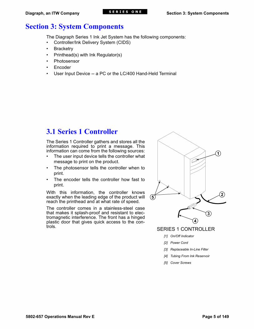
3.1 Series 1 ControllerThe Series 1 Controller gathers and stores all theinformation required to print a message. Thisinformation can come from the following sources:• The user input device tells the controller what
message to print on the product.• The photosensor tells the controller when to
print.• The encoder tells the controller how fast to
print.With this information, the controller knowsexactly when the leading edge of the product willreach the printhead and at what rate of speed.The controller comes in a stainless-steel casethat makes it splash-proof and resistant to elec-tromagnetic interference. The front has a hingedplastic door that gives quick access to the con-trols.
1
2
34
5
SERIES 1 CONTROLLER[1] On/Off Indicator
[2] Power Cord
[3] Replaceable In-Line Filter
[4] Tubing From Ink Reservoir
[5] Cover Screws

Diagraph, an ITW Company Section 3: System Components
Page 6 of 149 5802-657 Operations Manual Rev E
3.2 BracketryBracketry is the structure that supports the control-ler/IDS, printheads and other accessories.
The controller/IDS is mounted on the ControllerStand/Shelf Assembly (5760-361).
Printhead bracketry is modular and can assume several configurations: • Single pole conveyor mount• Double pole conveyor mount• Single pole floor mount• Double pole floor mount• Multi-panel floor mount
Controller
CONTROLLERSTAND/SHELFASSEMBLY
SINGLE POLECONVEYOR MOUNT
DOUBLE POLECONVEYOR MOUNT

Diagraph, an ITW Company Section 3: System Components
5802-657 Operations Manual Rev E Page 7 of 149
3.3 PrintheadsThe Diagraph Integrated ValveTM (I.V.)printhead uses a flexible membranesandwiched between two plates, whichby solenoid activation propels ink drop-lets onto moving surfaces.This design keeps the ink between thefront plate and membrane, away fromthe solenoids.The I.V. printhead is capable of printingat very high line speeds with a minimumof required maintenance. It can producehighly legible ¼” to 2” tall alphanumerics,special characters and logos.
Each type of I.V. printhead hasspecific distances above andbelow the orifices, spaces inwhich the printhead cannotprint. These non-printingzones are critical whendesigning printhead layout inmulti-head applications. Thefigure at right shows the printand non-print areas obtainedwhen two 9-dot printheads arestacked on a vertical bracket,as in the Single Pole FloorMount illustration earlier in thissection. Table 1 lists the eightmodels of I.V. printheads andtheir characteristics.
SINGLEPOLE
FLOORMOUNT
DOUBLE POLEFLOOR MOUNT
MULTI-PANEL FLOOR MOUNT
PRINTHEADINSIDE
PRINTINGZONE
A
B
A
B
PRINTINGZONE
ORIFICES
[A] Non-print Top Area [B] Non-print Base Area

Diagraph, an ITW Company Section 3: System Components
Page 8 of 149 5802-657 Operations Manual Rev E
3.4 Ink RegulatorThe ink regulator, supplied with the printhead, regulates ink pres-sure to the printhead. The regulator is preset at the factory to thecorrect output pressure.
Table 1: Printhead Models
PartNumber
Type Characteristics Non-printBaseArea (B)
Non-printTopArea (A)
Total Non-print Area(A+B)
5700-406 1/2" 9-dot Porous
Prints 1/4", 5/16" and 1/2" tall characters on
porous substrate
.800" 1.14" 1.94"
5700-407 1/2" 9-dot Non-porous
Prints 1/4", 5/16" and 1/2" tall characters on non-porous substrate
.800" 1.14" 1.94"
5700-404 7/8" 9-dot Porous
Prints 7/16", 5/8" and 7/8" tall characters on
porous substrate
.610" .93" 1.54"
5700-405 7/8" 9-dot Non-porous
Prints 7/16", 5/8" and 7/8" tall characters on non-porous substrate
.610" .93" 1.54"
5700-402 1" 18-dot Porous
Prints 1/4", 3/8", 1/2" and 1" tall characters on
porous substrate
2.14" 2.10" 4.24"
5700-403 1" 18-dot Non-porous
Prints 1/4", 3/8", 1/2" and 1" tall characters on non-
porous substrate
2.14" 2.10" 4.24"
5700-448 2" 18-dot Porous
Prints 1/4", 3/8", 1/2", 1" and 2" tall characters on
porous substrate
1.64" 1.42" 3.06"
5700-452 2" 18-dot Non-porous
Prints 1/4", 3/8", 1/2", 1" and 2" tall characters on
non-porous substrate
1.64" 1.42" 3.06"
5701-034 2" 18-dotPigmented
Prints 1/4", 3/8", 1/2", 1" and 2" tall characters
1.64" 1.42" 3.06"
INK REGULATOR

Diagraph, an ITW Company Section 3: System Components
5802-657 Operations Manual Rev E Page 9 of 149
3.5 PhotosensorThe photosensor is both a light source and a sensor. It emits light and detects the arrival ofa product when the product reflects the light source back to the sensor. The sensor thensends a signal to the controller to start the printing cycle. A red LED on the back of the sen-sor illuminates when a reflective object is detected.
3.6 EncoderThe variable speed encoder assembly (5700-731) provides conveyor line speed informa-tion to the controller. The controller offers abuilt-in fixed speed reporter or an optionalvariable speed encoder.Use the fixed speed reporter setting when theconveyor speed is constant and less than300 feet per minute. The desired line speedis set by turning a potentiometer on the inter-face board until print quality is acceptable.(See Section 5, Installation.)Use a variable speed encoder when the linespeed varies or has frequent starts and stops.In addition to providing line speed informa-tion, an encoder allows automatic disabling ofprinting when the line stops.
3.7 PC Software (PC-Based Systems Only)The IVpro software provides the following capabilities for the controller and printhead:• Creating or editing a message• Checking the status of a printhead or a printstation• Routing a message to a printhead• Performing utility functions
Potentiometer
PHOTOSENSOR BACK
LED
PHOTOSENSOR FRONT
ENCODER ASSEMBLY

Diagraph, an ITW Company Section 3: System Components
Page 10 of 149 5802-657 Operations Manual Rev E
3.8 LC/400 Hand-Held Terminal (Stand-Alone Systems Only)
In a stand-alone system, the LC/400 (5700-636) is theprimary tool for gaining access to the Series 1 system.It enables the user to perform the same functionslisted under PC Software, above.The LC/400 consists of a keypad and a liquid crystaldisplay (LCD). Color-coded keys divide the normalupper- and lower-case keys. In addition, there areeleven function keys to carry out specific tasks suchas moving the cursor or deleting a letter.The 40-character liquid crystal display shows the newor edited message. It also displays a stored message,information about the operating status of the system,and menu items.
1 3 4 5
6 7 8 9 ¢ A
B ? C " D [ E ( F <
G ! H ' I ] J ) K >
L M N O / P =
Q R S : T U ®
V { W ' X . Y , Z }
& % #$
+ -
^
SHIFTON SP
*
CASEMENU
LOCKENTER 0
ERASE CANCEL2 DEL

Diagraph, an ITW Company Section 4: Getting Started
5802-657 Operations Manual Rev E Page 11 of 149
Section 4: Getting StartedController descriptions contain the following abbreviations for distinguishing features:• 1-PH: Designed to operate a single printhead• 2-PH: Designed to operate two printheads• 4-PH: Designed to operate four printheads• MS: Message Select• NP: Non-porous for inks designed to adhere to non-porous surfaces• P: Porous for inks designed for absorptive surfaces• SA: Stand Alone• PC-Based: Designed to run from a computer interface with Diagraph IVpro software
The Series 1 system is available with the following components, options and service kits:
Table 2: Controller Types
Domestic/European Controllers Japanese Controllers
Part No. Description Part No. Description
5700-996NP SA-99MS 2-PH NP 5700-802NP SA-99MS 1-PH NP
5700-996P SA-99MS 2-PH P 5700-802P SA-99MS 1-PH P
5700-998NP SA-99MS 4-PH NP 5700-803P SA-99MS 2-PH P
5700-998P SA-99MS 4-PH P 5700-805P SA-99MS 4-PH P
5701-002NP PC-Based 2-PH NP 5700-807P SA-99MS 4-PH Multi-Tasking P
5701-002P PC-Based 2-PH P 5700-808NP PC-Based 1-PH NP
5701-004NP PC-Based 4-PH NP 5700-808P PC-Based 1-PH P
5701-004P PC-Based 4-PH P 5700-811P PC-Based 4-PH P
5700-812P PC-Based 2-PH Multi-Tasking P
Table 3: Series 1 Components
Part Number Description
Controller/IDS Accessories
5760-361 Controller stand/shelf assembly
5701-038 Software, CD
1301-875 50’ x ¼" bev-a-line tubing
1901-141 Power cord
5700-991 Ink filter kit
5700-277 Spare parts kit
5700-209 ¼" elbow barb quick disconnect

Diagraph, an ITW Company Section 4: Getting Started
Page 12 of 149 5802-657 Operations Manual Rev E
5700-508 ¼" barb quick disconnect
5700-934 Controller to printhead cable assembly, 25’
5700-967 Ink out beacon
5700-994 Effluent kit
1902-964 Flush bottle assembly
5700-743 Ink pressure gauge
5700-962 Replacement accumulator
5700-966 Replacement pump assembly
Standard Integrated Valve (IV) Printheads
5700-406 ½" 9-dot porous
5700-407 ½" 9-dot non-porous
5700-404 7/8" 9-dot porous
5700-405 7/8" 9-dot non-porous
5700-402 1" 18-dot porous
5700-403 1" 18-dot non-porous
5700-448 2" 18-dot porous
5700-452 2" 18-dot non-porous
5701-034 2" 18-dot pigmented
Printhead Bracketry
5760-353 Single printhead conveyor mounting kit
5760-354 Multi printhead conveyor mounting kit (requires single printhead kits)
5760-355 Printhead floor mounting kit (requires single printhead kits)
5760-356 Multi head floor mounting kit with 24" bar (requires single head kits)
5760-357 Multi head floor mounting kit with 44" bar (requires single head kits)
5760-360 Printhead angle bracket with T-nuts
Printhead Cables
5700-245 Printhead cable assembly, 2’
5700-727 Printhead cable assembly, 10’
5700-934 Printhead cable assembly, 25’
Table 3: Series 1 Components (Continued)
Part Number Description

Diagraph, an ITW Company Section 4: Getting Started
5802-657 Operations Manual Rev E Page 13 of 149
Encoder
5700-731 Encoder assembly with mounting bracket
5700-924 Encoder 10’ extension cable
Photosensor
5700-216 Photosensor, diffuse type
5700-933 Photosensor 10’ extension cable
5700-435 Photosensor optional mounting bracketry
Table 3: Series 1 Components (Continued)
Part Number Description

Diagraph, an ITW Company Section 4: Getting Started
Page 14 of 149 5802-657 Operations Manual Rev E
Diagraph, an ITW Company Section 5: Installation
5802-657 Operations Manual Rev E Page 15 of 149
Section 5: Installation
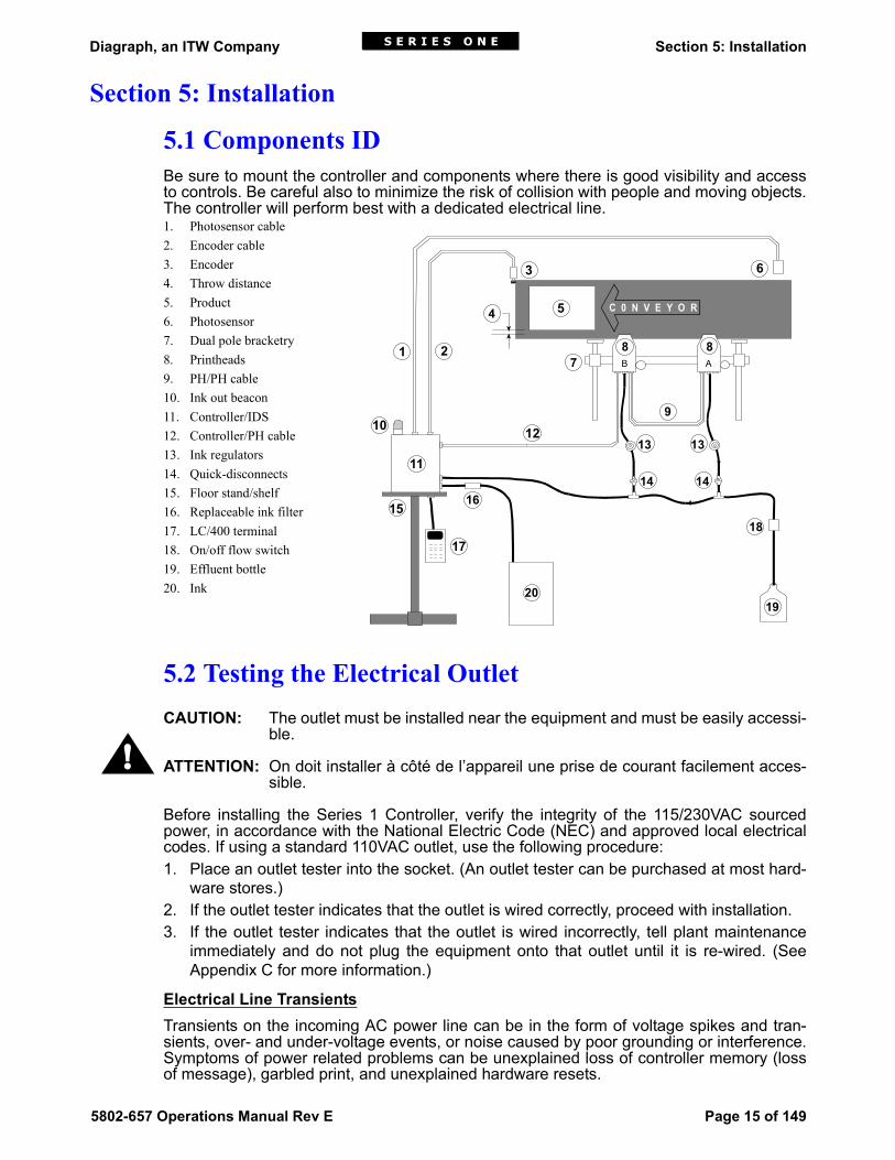
5.1 Components IDBe sure to mount the controller and components where there is good visibility and accessto controls. Be careful also to minimize the risk of collision with people and moving objects.The controller will perform best with a dedicated electrical line.1. Photosensor cable2. Encoder cable3. Encoder4. Throw distance5. Product6. Photosensor7. Dual pole bracketry8. Printheads9. PH/PH cable10. Ink out beacon11. Controller/IDS12. Controller/PH cable13. Ink regulators14. Quick-disconnects15. Floor stand/shelf16. Replaceable ink filter17. LC/400 terminal18. On/off flow switch19. Effluent bottle20. Ink
5.2 Testing the Electrical OutletCAUTION: The outlet must be installed near the equipment and must be easily accessi-
ble.
ATTENTION: On doit installer à côté de l’appareil une prise de courant facilement acces-sible.
Before installing the Series 1 Controller, verify the integrity of the 115/230VAC sourcedpower, in accordance with the National Electric Code (NEC) and approved local electricalcodes. If using a standard 110VAC outlet, use the following procedure:1. Place an outlet tester into the socket. (An outlet tester can be purchased at most hard-
ware stores.)2. If the outlet tester indicates that the outlet is wired correctly, proceed with installation.3. If the outlet tester indicates that the outlet is wired incorrectly, tell plant maintenance
immediately and do not plug the equipment onto that outlet until it is re-wired. (SeeAppendix C for more information.)
Electrical Line TransientsTransients on the incoming AC power line can be in the form of voltage spikes and tran-sients, over- and under-voltage events, or noise caused by poor grounding or interference.Symptoms of power related problems can be unexplained loss of controller memory (lossof message), garbled print, and unexplained hardware resets.
C 0 N V E Y O R
B A
6
8
9
4
1312
21
11
15
20
3
8
17
5
7
13
1414
18
19
16
10
!

Diagraph, an ITW Company Section 5: Installation
Page 16 of 149 5802-657 Operations Manual Rev E
The best way to eliminate these types of problems is to install the controller on a dedicatedline with a line conditioner. A dedicated line refers to an AC line that only the system com-ponents are plugged into. This is most effective when the source is at the building mainservice entrance. Good quality line conditioners will provide protection against all AC line problems with theexception of power outages; if power outages are a problem at the installation, an uninter-ruptible power supply (UPS) should be installed. CAUTION: Not for use in a computer room as defined in the Standard for the Protection ofElectronic Computer/Data Processing Equipment, ANSI/NFPA 75.ATTENTION: Ne peut être utilissé dans une salle d'ordinateurs telle que définie dans lasnorme ANSI/NFPA 75 Standard for Protection of Electronic Computer/Data ProcessingEquipment.
5.3 Materials Required for InstallationYou will need the following items:• Bottle of conditioner• Lint-free wipes• Socket wrench• 1/4" nut driver• Set of Allen wrenches• Ink pressure gauge (5700-743)• Safety goggles• Level• Tape measure• Effluent bottle (5700-994)Use appropriate safety equipment and procedures. Leave printheads in their shipping car-tons until all bracketry is in place and tightened down.
5.4 Installing Bracketry
The controller/IDS is mounted onthe Controller Stand/Shelf Assem-bly (5760-361). Follow the assem-bly instructions included with theparts kit. The illustrations in this sectionshow printhead mounting via singlepole conveyor mounted bracketry.See Section 3, System Compo-nents, for other printhead bracketryoptions. With all conveyor-mounted options,plant maintenance will need to drillholes in the conveyor for finalattachment.
!
VERTICAL BARWITH CORNERBRACKETS
CONVEYOR WITHPRINTHEAD BRACKETRY
Horizontal Bar
Vertical Bar

Diagraph, an ITW Company Section 5: Installation
5802-657 Operations Manual Rev E Page 17 of 149
5.5 Mounting Printheads
Unpack the printhead(s) just beforemounting on the bracketry.Attach the printhead to the bracketrywith a printhead mounting bracket asshown.You may need to vertically adjusteach bracket’s horizontal bar later tofine-tune message placement. This isespecially true when using multipleprintheads, as message lines willneed to be synchronized with eachother.The maximum vertical density ofstacked 9-dot printheads is four. Themaximum vertical density of stacked18-dot printheads is two.NOTE: When adjusting the horizontalbar or printhead mounting bracket,always support the printhead withyour hand to keep it from falling forward onto the conveyor.
5.6 Mounting Photosensor Bracketry (5700-435)
1. Drill two holes into the conveyor using thephotosensor bracket base to mark the drillholes.
2. Attach the base to the conveyor.3. Slide the vertical bar into the base and
tighten in place.4. Slide the crossbar into the horizontal
clamp and tighten with an Allen wrench.
5.7 Mounting the PhotosensorPosition the photosensor (5700-216) approximately two inches upstream from the firstprinthead. The maximum placement distance is 99.9 inches minus the distance betweenthe leading edge of the target item and the point where the message begins on the sub-strate. The distance between the photosensor and the farthest printhead must be less thanthe distance between products (leading edge to leading edge) to guarantee that all print-heads have finished printing on the first item before the next item reaches the photosensor.The photosensor depth range can be adjusted by turning the sensitivity potentiometer onthe back of the photosensor. The photosensor normally has a range of about 30", but canbe adjusted down to about 6".CAUTION: The shorter the range, the more sensitive photosensor triggering is, increasingthe possibility of false triggers from graphics on the product. It is best not to adjust sensitiv-ity unless the 30" range is causing false triggers.
MOUNTING APRINTHEAD
To Controller
Conveyor

Diagraph, an ITW Company Section 5: Installation
Page 18 of 149 5802-657 Operations Manual Rev E
5.8 Photosensor Sensitivity AdjustmentIf product sensing problems exist (not detecting product, multiple or false trips), the photo-sensor sensitivity may require adjustment.1. Ensure that the photosensor is positioned per-
pendicular to the product.2. Turn sensitivity potentiometer (located on the
rear of the photosensor housing) counter-clockwise 10 turns to limit its depth range.
3. Place object to be sensed approximately in thecenter of the conveyor, and rotate the sensitiv-ity potentiometer slowly clockwise until thephotocell LED illuminates.
4. Move object to the sensing distance seen innormal operation (should be less than dis-tance in step 3). Slowly move object back and forth in front of photosensor while moni-toring the LED. The LED should remain on throughout the length of the object. If theLED turns off on any part of the object, increase sensitivity until the LED remains illumi-nated throughout the length of the object.
5. Remove object; check that the photosensor is not sensing objects on the opposite sideof the conveyor.
5.9 The EncoderIn applications where the con-veyor line speed varies greatly, orwhere there are frequent startsand stops, it may be necessary toinstall an external encoder (5700-731). The encoder uses a wheelthat rolls against the conveyorline to track its speed. It sends asignal to the controller, whichmakes adjustments for reportedchanges in the line speed.It is not necessary to install theencoder immediately adjacent tothe printheads. It is more impor-tant to place it where it will accu-rately measure the speed of theconveyor. Install it in contact withthe conveyor, or with a wheel orroller moving the same speed asthe conveyor.The encoder’s mounting bracket is spring-loaded. Adjust the spring collar to ensure thatthe encoder maintains stable contact with the conveyor.NOTE: Do not jam the encoder wheel against the surface of the conveyor. A radial force ofover 40 lbs. will reduce the life of the bearings.
Potentiometer
PHOTOSENSOR BACK
LED
Spring
MountingBracket
Encoder Wheel
Conveyor
Out to Controller
Mounting BracketShaft
Encoder
ENCODERASSEMBLY

Diagraph, an ITW Company Section 5: Installation
5802-657 Operations Manual Rev E Page 19 of 149
5.10 Setting Up the Stand/Shelf Assembly
The stand/shelf assembly (5760-361) elevates thecontroller to a height convenient for operations.1. Assemble the T-stand per instruction sheet 5760-
361N.2. Remove the rubber feet from the bottom of the
controller.3. Place the controller on top of the shelf and posi-
tion it so that the front panel is easily accessible.4. Using the screws and rubber foot spacers from
the bottom of the controller, securely mount thecontroller to the shelf.
5.
5.11 Controller Connections
Removing the Cover1. Place the controller on a workbench.2. Open the hinged door at the front of the unit.3. Loosen the six cover screws with a slot head screw-
driver.4. Slide the cabinet housing up and set it aside.5. Be sure to plug in the 5V/15V power supply and the
ink out beacon. (Consult the label located on the rearpanel of the IDS.)
The controller requires a constant electrical source. Aproperly grounded, dedicated line is recommended forink jet equipment. A dedicated line minimizes the risk ofinterruptions in the printing process due to power lineinterference. If using an electrical source other than115VAC, set the voltage selector switch to the correctvoltage.
Controller
CONTROLLERSTAND/SHELFASSEMBLY
CONTROLLER WITHCOVER OFF

Diagraph, an ITW Company Section 5: Installation
Page 20 of 149 5802-657 Operations Manual Rev E
Cable ConnectionsVerify that the 5VDC, 15VDC and Ink Out cables are connected to the interface board. TheDB15 cable should be attached to the DATA port.Gather the remaining cables that came with your system. When routing cables, make surethat ALL cables connecting to the controller pass through the base plate of the controllerBEFORE they are attached to their ports. 1. Controller to First Printhead
Attach the Printhead-Controller cable (5700-934) with the female DB15 connector tothe printhead. Tighten in place with the attached jack screws.Slide the other end of the control cable with the male DB15 connector through the slotin the base plate and attach it to the controller. Consult the card cage silkscreen for theconnector marked HEADS. Tighten in place with the attached jack screws.
2. First Printhead to Second PrintheadAttach the Printhead-Printhead cable (5700-934) with the male connector to the firstprinthead. Tighten in place with the attached jack screws.Attach the other end of the printhead cable (with the female connector) to the next print-head in the printstation and tighten in place with the attached jack screws.
3. LC/400 Holster to ControllerConnect the DB25 end of the LC/400-PHC cable into the slot on the optionalLC/400 holster (5700-295). Tighten withthe jack screws and standoffs supplied.Use a nut driver to tighten in place.Slide the DB15 end of the LC/400-Con-troller cable through the slot in the baseplate and attach it to either DATA porton the rear panel of the controller.
4. Encoder to ControllerDisregard this step if you are using theinternal fixed speed reporter. Slide the DB15 end of the Encoder-Controller cable (5700-924), attached tothe encoder, through the slot in thebase plate and attach it to the controller. Consult the card cage silkscreen for the con-nector marked ENCODER.
5. Photosensor to ControllerSlide the DB9 end of the Photosensor-Controller cable (5700-933), attached to thephotosensor, through the slot in the base plate and attach it to the controller. Consultthe card cage silkscreen for the connector marked PHOTOCELL.
Securing Loose CableAfter making all cable connections, use plastic tie-wraps or similar straps to secure slacklengths of unused cable. Do not attempt to cut the cables to length.

Diagraph, an ITW Company Section 5: Installation
5802-657 Operations Manual Rev E Page 21 of 149
Interface Board SettingsRefer to the following diagrams for the proper jumper settings for your configuration.

Diagraph, an ITW Company Section 5: Installation
Page 22 of 149 5802-657 Operations Manual Rev E

Diagraph, an ITW Company Section 5: Installation
5802-657 Operations Manual Rev E Page 23 of 149

Diagraph, an ITW Company Section 5: Installation
Page 24 of 149 5802-657 Operations Manual Rev E

Diagraph, an ITW Company Section 5: Installation
5802-657 Operations Manual Rev E Page 25 of 149
Setting DIP Switches on the Logic BoardsThe system uses dual in-line package (DIP) switches toset the printhead addresses and to add or remove certainfeatures. These eight switches are on the Controller logicboards.Each pair of logic boards (with an attached interfaceboard) can power up to two 9-dot printheads or one 18-dot printhead. The controller canhouse as many as two sets of boards; thus controlling up to four 9-dot printheads or two18-dot heads. Each logic board contains a block of eight DIP switches that perform func-tions described in the table below.DIP switch settings 1-4 can be changed when the power is ON. Always turn the power OFFwhen changing DIP switch settings 5-8.
Table 4: DIP Switch Functions
Switch # Function
1 If ON, a test message will print when the system is running, even withoutsending a message to print. Turn OFF for normal operation.
2 In the SA99 system, turn ON if printing is to be on a continuous, unbrokensurface. Turn OFF to print once per product.
3 OFF to identify the lower half of an 18-dot printhead. ON when configured for18-dot.
4 Sets special options. Always keep this OFF during normal operation. Moreinformation on setting special options is found later in this section.
5-8 Set these switches to the proper printhead addresses as detailed below.
1 2 3 4 5 6 7 8

Diagraph, an ITW Company Section 5: Installation
Page 26 of 149 5802-657 Operations Manual Rev E
NOTE: Some logic boards label the DIP switches OPEN or CLOSED, rather than OFF orON. In this case, OPEN is the same as OFF and CLOSED is the same as ON.
Setting Printhead AddressesFor a single head stand-alone system, set switches 5-7 to ON and 8 to OFF. For a multiplehead system, assign each printhead controller logic board, with its respective printhead, aletter from A through O. This is the "Printhead Address". Do not duplicate addresses.Determine the lettering scheme by assigning letters to all the logic boards in your systembeginning with the letter A. Mark each logic board visibly with its address letter or number.Next, set the last four DIP switches (5-8) on each labeled logic board to correspond to itsassigned letter or number according to the tables below.
Table 5: Printhead Addresses for the PC-Based Controller
SW 1 2 3 4 5 6 7 8 9 10 11 12 13 14 15 16
5 off off off off off off off off ON ON ON ON ON ON ON ON
6 off off off off ON ON ON ON off off off off ON ON ON ON
7 off off ON ON off off ON ON off off ON ON off off ON ON
8 off ON off ON off ON off ON off ON off ON off ON off ON
Table 6: Printhead Addresses for the Stand-Alone Controller
SW A B C D E F G H I J K L M N O
5 off off off off off off off ON ON ON ON ON ON ON ON
6 off off off ON ON ON ON off off off off ON ON ON ON
7 of ON ON off off ON ON off off ON ON off off ON ON
8 ON off ON off ON off ON off ON off ON off ON off ON

Diagraph, an ITW Company Section 5: Installation
5802-657 Operations Manual Rev E Page 27 of 149
Setting the Fixed Speed ReporterThe fixed speed reporter approximates the speed of the conveyor line and sends a con-stant speed signal to the controller. The operator must properly set a suitable approximateprint speed to send to the controller because the fixed speed reporter does not make con-tact with the conveyor.1. Make sure that jumper P18 is in the front position.2. Run a print sample.3. If the message appears elongated, use a slotted tip screwdriver and turn the potentiom-
eter for the fixed speed reporter clockwise several turns. This increases both the linespeed being reported to the controller and the rate the dots are printed. The net resultis a compressed image.
4. Print another sample and adjust as necessary.5. Continue this process until the print quality is acceptable.6. If the message appears too compressed, turn the potentiometer counterclockwise. This
decreases the rate at which the dots are printed, and elongates the image.7. Print another sample and adjust as necessary. Continue this process until print quality
is acceptable.
NOTE: The maximum line speed of the fixed speed reporter is 300 feet per minute.
Calculating the Print IndentationPrint Indentation, or Start Print Delay, is the distancefrom the leading edge of the product to the start ofprinting. This will be the distance to the start of themessage for right-to-left printing, and to the end ofthe message for left-to-right printing.Two distances must be taken into account beforesetting the print indentation:1. The distance between the photosensor and the
nozzle array of the printhead (A to B in the figureat right).
2. The distance between the leading edge of thetarget item and the point on the item where themessage will begin printing (C to D). The leadingedge depends on the direction the conveyor ismoving.
3. Step 1 + Step 2 = Print Indentation.You will need to calculate the print indentation foreach printhead.
Setting the Indentation for SA99 and PC-Based SystemsThe Start Print Delay adjustment for the SA99 system is set with three rotary thumbwheelswitches on each logic board in the controller. These switches, from top to bottom, are cal-ibrated in 10", 1" and 0.1" increments.1. Locate the three rotary thumbwheels on the logic board.2. Turn the wheels until the appropriate numbers are showing. To create a print indenta-
tion of 24.5", set the thumbwheels as shown at left.Remember to set the Start Print Delay for each logic board.
STOCK264-96
CD
BA
STOCK264-96
CDB A
4
5
2

Diagraph, an ITW Company Section 5: Installation
Page 28 of 149 5802-657 Operations Manual Rev E
Selecting Indentation for the SA99 Message SelectEnter the message indentation for the SA99 Message Select system through the LC/400hand-held terminal. Set Indentation appears under the Utility menu.1. Turn on the controller and when the LCD asks for a new printhead, type the printhead
letter address for the appropriate printhead.2. Scroll through menus and select the Utility menu option.3. Scroll through the Utility menu functions to the Set Indentation screen. Answer yes by
pressing Y and the screen will display the current indentation screen.4. Type in the new indentation value. Remember, the value displayed represents hun-
dredths of an inch: 1200 = 12 inches, and 2400 = 24 inches. 5. The LCD will flash the new indentation value and then ask if you want to print in contin-
uous (web) mode. Press SP for NO if you want to print single messages on individualitems.
Continuous Printing (SA99 or PC System)To print on a continuous, unbroken surface like a roll of fabric or paper, set the Start PrintDelay to print the same message continuously at regular intervals.1. Open the hinged front door of the controller/IDS.2. Turn on DIP switch #2.3. Set the thumbwheels to the desired distance between printed messages.4. Turn the RUN/STOP switch to RUN.5. Start the conveyor.If using an SA99 Message Select system, activate the continuous (web) printing mode byselecting YES in step 5 of the previous section.NOTE: An SA99 or PC system is adequate if the distance between prints in web mode isequal to the repeat distance. If the distance from the start of print to the leading edge of theproduct cannot equal the repeat distance, an SA99 Message Select system is required.
Diagraph, an ITW Company Section 5: Installation
5802-657 Operations Manual Rev E Page 29 of 149
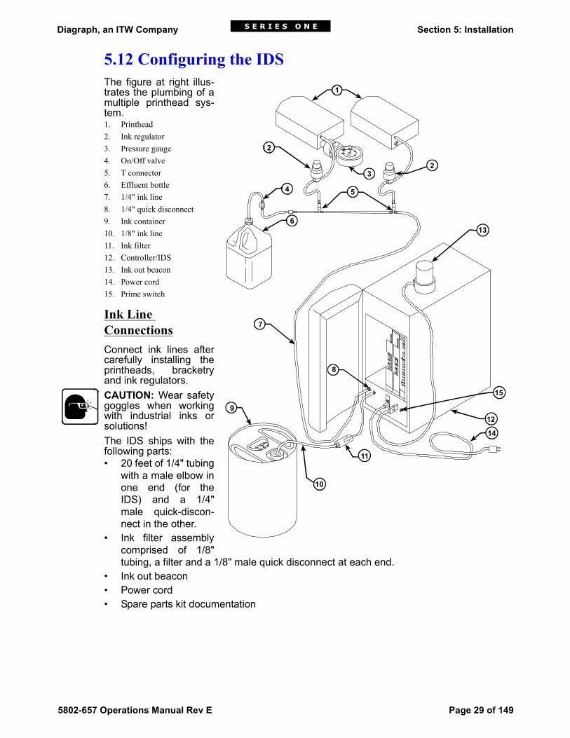
5.12 Configuring the IDSThe figure at right illus-trates the plumbing of amultiple printhead sys-tem.1. Printhead2. Ink regulator3. Pressure gauge4. On/Off valve5. T connector6. Effluent bottle7. 1/4" ink line8. 1/4" quick disconnect9. Ink container10. 1/8" ink line11. Ink filter12. Controller/IDS13. Ink out beacon14. Power cord15. Prime switch
Ink Line ConnectionsConnect ink lines aftercarefully installing theprintheads, bracketryand ink regulators.CAUTION: Wear safetygoggles when workingwith industrial inks orsolutions!The IDS ships with thefollowing parts:• 20 feet of 1/4" tubing
with a male elbow inone end (for theIDS) and a 1/4"male quick-discon-nect in the other.
• Ink filter assemblycomprised of 1/8"tubing, a filter and a 1/8" male quick disconnect at each end.
• Ink out beacon• Power cord• Spare parts kit documentation
1
2
23
54
6
11
9
7
8
12
13
14
15
10

Diagraph, an ITW Company Section 5: Installation
Page 30 of 149 5802-657 Operations Manual Rev E
Attaching Ink RegulatorsAttach a single T-nut loosely to the bottom side ofthe regulator bracket.Slide the regulator bracket and T-nut into the slot-ted bar and tighten into place.
Plumbing the SystemObtain a pair of diagonal cutters to cut the cableties and tubing1. The IDS may be located up to 100 feet away
from the printheads. Refer to Appendix E,"IDS Performance", to ensure that the verticaldistance between the IDS and the printheadsallows for adequate ink pressure.
2. Be sure to slide the tubing completely over theexposed barbs on the fittings to prevent inkline leaks while under pressure.
3. Construct a spine from the 1/4" tubing and the T connectors, one connector for eachregulator. Plan to position each regulator conveniently close to the printhead it will sup-ply.
4. To connect the IDS to the first printhead, start at the end of the tubing fitted with theelbow connector. Cut the tubing and insert the barbed end of a T connector.
5. Reconnect the tubing to the other barb on the T connector and route the tubing to thenext regulator.
6. Cut the tubing and insert the barbed end of a T connector for the second regulator.7. Repeat the previous steps until there is a T connector in the supply line for each regula-
tor. Connect the male quick disconnect of the T connector to the female quick discon-nect of the regulator.
8. Attach the cut end of the remaining 1/4" tubing to the last printhead T connector.9. Cut the tubing off about six inches beyond the last T connector and insert the male
quick disconnect. Connect to the female quick disconnect on the tube from the effluentbottle.
10. Connect the male elbow in the 1/4" tubing to the female quick disconnect marked OUTon the IDS.
Connecting the PrintheadsConnect the ink line with the male fitting from each regulator to the female quick disconnecton its printhead. Listen for a click when you push the connector into the fitting. The thumbtab on the coupling will be in its out position when successfully attached. Test the ink line’ssecurity by gently tugging on it to ensure connection.
Regulator Bracket
Regulator
Correct Incorrect

Diagraph, an ITW Company Section 5: Installation
5802-657 Operations Manual Rev E Page 31 of 149
Connecting the Beacon to the IDSSet the Ink Out beacon where it can be seen by floor personnel. Connect the beacon to theIDS front panel using the attached cable with the two-pin connector. The beacon will flashwhen the ink pail is empty or an error condition exists.
Connecting the Ink SupplyCAUTION: Wear safety goggles whenever working with ink or ink supply lines. Check withyour supervisor for additional safety directives.1. Place a pail of Diagraph ink on the floor near the IDS.2. Remove the plastic cap and tube assembly attached to the side of the pail. The cap is
designed to remove the maximum amount of ink from the pail. Do NOT cut it or reposi-tion the weight on its end.
3. Unscrew the plastic shipping cap and dispose of it.4. Insert the tube from the cap and tube assembly into the pail and screw the cap on
tightly.5. Connect the 1/8" ink supply line from the IDS to the female quick disconnect in the ink
cap. Make sure the couplings snap into place.
Connecting Power to the Controller/IDSBe sure that the ON/OFF switch [2] is set to OFF (0).
Check the window [1] at the top of the power module for the correct voltage setting. Plugthe power cord from the junction box into the power entry module input [3].
PrimingCAUTION: Do not run pressurized ink before all ink line connections are made.Priming is a manual procedure that draws ink from the pails and fills the system’s ink lines.This is necessary for all new installations or whenever the system has run out of ink com-pletely.1. Before beginning, make sure the controller is off.2. Check all ink line fittings again to ensure they are intact so no ink will leak.3. Turn the ON/OFF switch to ON. The power LED illuminates and the Ink Out beacon
flashes, indicating that the system is out of ink.
INKOUT
INKIN
BEACON PRIME
[1] [2]
[3]
[1] Voltage Indicator
[2] ON/OFF Switch
[3] Power Entry Module
115
!

Diagraph, an ITW Company Section 5: Installation
Page 32 of 149 5802-657 Operations Manual Rev E
4. Open the shutoff valve in the inktubing to the effluent bottle bypushing the connectors together.
5. For the next three steps, positionyourself so that you can reachboth the Prime button and the in-line shutoff valve while keepingan eye on the Ink Out beacon.
6. Press and hold the Prime button,which turns the pump on. After 5seconds, close the shutoff valveby depressing the metal tab onthe valve, while continuing to holdthe Prime button.
7. Release the Prime button whenthe beacon stops flashing. Thesystem will continue to pressurizeuntil the accumulator becomesfull of ink.NOTE: If manual primingexceeds 30 seconds, the pumpwill shut off, the power LED willflash and the beacon will illuminate, indicating an error condition.
8. Optional: If there is air in the lines at the effluent bottle, exhaust by quickly opening andclosing the shutoff valve.
9. If the system failed to prime, see Section 8, Troubleshooting.10. If the beacon continues to flash, check for an ink leak. If a leak is a discovered, turn off
the controller, disconnect the ink line from the primary ink pail and fix the leak.11. If there is no leak but the beacon continues to flash, see Section 8, Troubleshooting.
Checking Ink PressureVariations in ink pressure produce different dotsizes; the higher the pressure, the larger thedot. NOTE: One should not adjust dot size byadjusting ink pressure. Over-pressurizing aprinthead can result in leakage, or cause ink toshoot across the conveyor. Under-pressurizingcan cause ink to drip from the front plate whileprinting.Connect the pressure gauge with its femalequick-disconnect to the effluent port on theprinthead. The needle on the gauge will reflectthe ink pressure at the printhead.
CLOSE SHUTOFF VALVE
MetalTab
OPEN SHUTOFF VALVE
PressureGauge
Regulator
Diagraph, an ITW Company Section 5: Installation
5802-657 Operations Manual Rev E Page 33 of 149
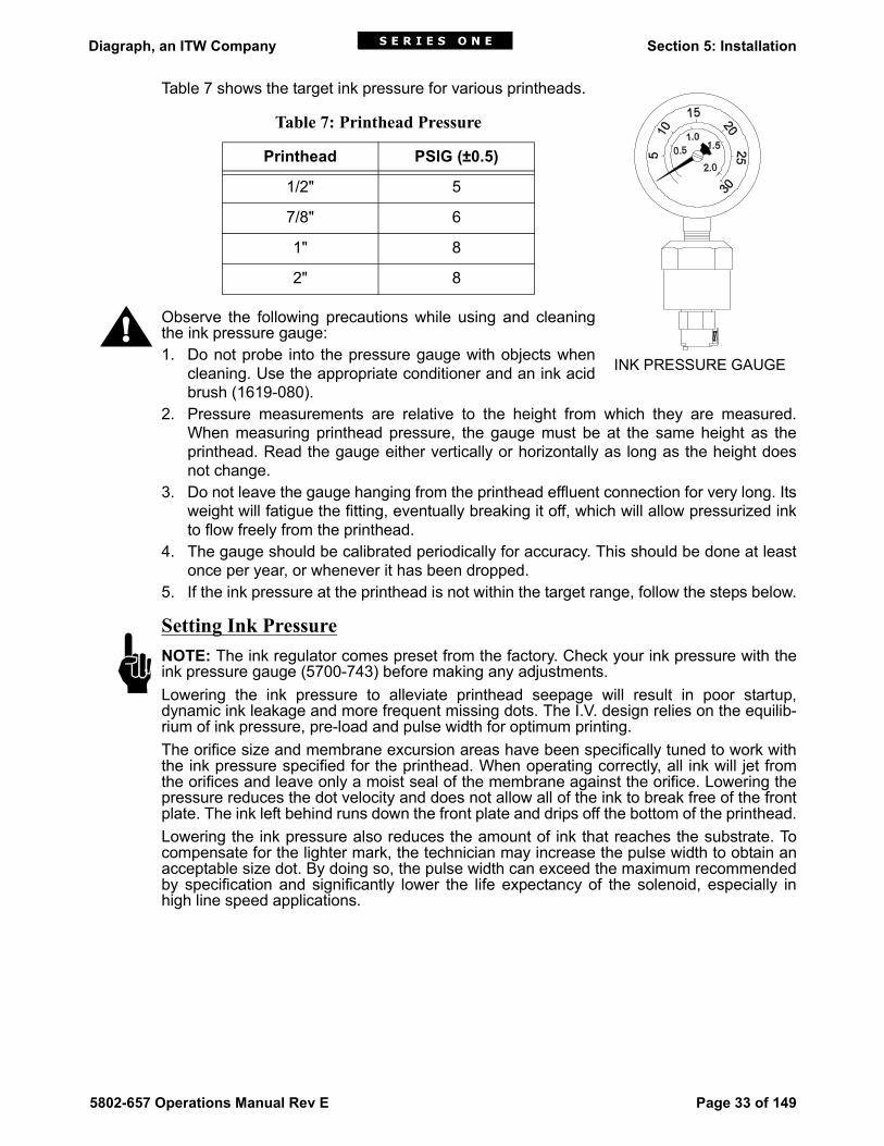
Table 7 shows the target ink pressure for various printheads.
Observe the following precautions while using and cleaningthe ink pressure gauge:1. Do not probe into the pressure gauge with objects when
cleaning. Use the appropriate conditioner and an ink acidbrush (1619-080).
2. Pressure measurements are relative to the height from which they are measured.When measuring printhead pressure, the gauge must be at the same height as theprinthead. Read the gauge either vertically or horizontally as long as the height doesnot change.
3. Do not leave the gauge hanging from the printhead effluent connection for very long. Itsweight will fatigue the fitting, eventually breaking it off, which will allow pressurized inkto flow freely from the printhead.
4. The gauge should be calibrated periodically for accuracy. This should be done at leastonce per year, or whenever it has been dropped.
5. If the ink pressure at the printhead is not within the target range, follow the steps below.
Setting Ink PressureNOTE: The ink regulator comes preset from the factory. Check your ink pressure with theink pressure gauge (5700-743) before making any adjustments.Lowering the ink pressure to alleviate printhead seepage will result in poor startup,dynamic ink leakage and more frequent missing dots. The I.V. design relies on the equilib-rium of ink pressure, pre-load and pulse width for optimum printing.The orifice size and membrane excursion areas have been specifically tuned to work withthe ink pressure specified for the printhead. When operating correctly, all ink will jet fromthe orifices and leave only a moist seal of the membrane against the orifice. Lowering thepressure reduces the dot velocity and does not allow all of the ink to break free of the frontplate. The ink left behind runs down the front plate and drips off the bottom of the printhead.Lowering the ink pressure also reduces the amount of ink that reaches the substrate. Tocompensate for the lighter mark, the technician may increase the pulse width to obtain anacceptable size dot. By doing so, the pulse width can exceed the maximum recommendedby specification and significantly lower the life expectancy of the solenoid, especially inhigh line speed applications.
Table 7: Printhead Pressure
Printhead PSIG (±0.5)
1/2" 5
7/8" 6
1" 8
2" 8
INK PRESSURE GAUGE
!
Diagraph, an ITW Company Section 5: Installation
Page 34 of 149 5802-657 Operations Manual Rev E
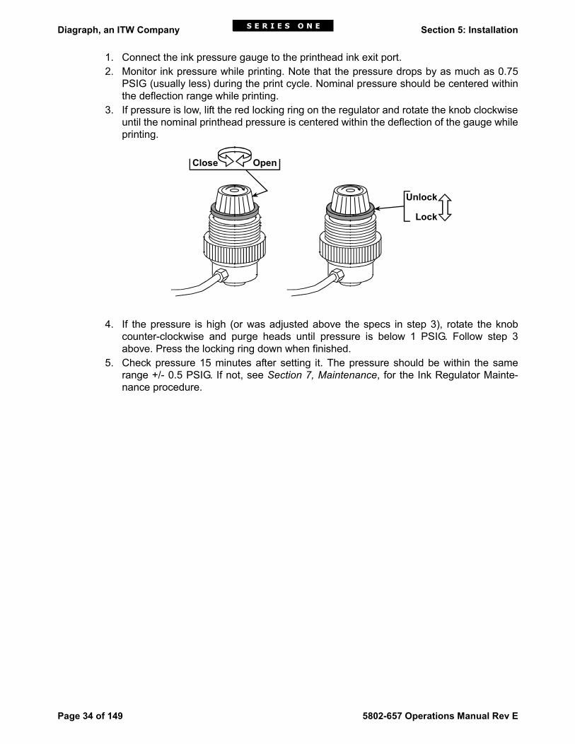
1. Connect the ink pressure gauge to the printhead ink exit port.2. Monitor ink pressure while printing. Note that the pressure drops by as much as 0.75
PSIG (usually less) during the print cycle. Nominal pressure should be centered withinthe deflection range while printing.
3. If pressure is low, lift the red locking ring on the regulator and rotate the knob clockwiseuntil the nominal printhead pressure is centered within the deflection of the gauge whileprinting.
4. If the pressure is high (or was adjusted above the specs in step 3), rotate the knobcounter-clockwise and purge heads until pressure is below 1 PSIG. Follow step 3above. Press the locking ring down when finished.
5. Check pressure 15 minutes after setting it. The pressure should be within the samerange +/- 0.5 PSIG. If not, see Section 7, Maintenance, for the Ink Regulator Mainte-nance procedure.
Unlock
Lock
Close Open

Diagraph, an ITW Company Section 5: Installation
5802-657 Operations Manual Rev E Page 35 of 149
Final Installation Checklist1. Record all serial numbers and revision levels below for future reference.
2. Program the controller and/or PC with custom software if required. Load any specialforms or logos.
3. Test print samples. Verify that the system downloads information correctly, and thatprint quality is consistent.
4. Confirm the type of barcodes to be printed. Print and verify the barcodes with RJSModel 2 Verifier.
5. Remove the inlet ink line while the system is ON to verify that the low ink indicators areworking on the interface and logic boards, and the ink out beacon is working.
6. Record the jumper settings on the interface board, and the DIP switches on logicboards.
Interface Board 1 Jumpers (Circle Connections)
MODEL # SERIAL # REV. LEVEL#
Interface Board 1
Interface Board 2
Logic Board 1
Logic Board 2
Logic Board 3
Logic Board 4
Power Supply
Printhead 1
Printhead 2
Printhead 3
Printhead 4
Firmware Version
Software Version
Controller
LC/400 Terminal
Portable Terminal
PC Base
• • P4 P18 P20
• • • • • • •
• • • •

Diagraph, an ITW Company Section 5: Installation
Page 36 of 149 5802-657 Operations Manual Rev E
Interface Board 2 Jumpers
Logic Board 1 DIP Switches (Check Boxes)
Logic Board 2 DIP Switches
Logic Board 3 DIP Switches
• • P3 • • • P12 • •
• • • • • P14
• • I • • • P15 • • • J15
• • • P16
• • P4 P18 P20
• • • • • • •
• • • •
• • P3 • • • P12 • •
• • • • • P14
• • I • • • P15 • • • J15
• • • P16
1 2 3 4 5 6 7 8
NONE
1 2 3 4 5 6 7 8
NONE
1 2 3 4 5 6 7 8
NONE

Diagraph, an ITW Company Section 5: Installation
5802-657 Operations Manual Rev E Page 37 of 149
Logic Board 4 DIP Switches
Logic Board 1 Jumpers (Circle Connections)
Logic Board 2 Jumpers
Logic Board 3 Jumpers
1 2 3 4 5 6 7 8
NONE
H G F EDC A
• • • • • • • • •
• • • • • • • • •
• • • • • • • •
B • • F • • E • • D • •
• • • • • • • •
H G F EDC A
• • • • • • • • •
• • • • • • • • •
• • • • • • • •
B • • F • • E • • D • •
• • • • • • • •
H G F EDC A
• • • • • • • • •
• • • • • • • • •
• • • • • • • •
B • • F • • E • • D • •
• • • • • • • •

Diagraph, an ITW Company Section 5: Installation
Page 38 of 149 5802-657 Operations Manual Rev E
Logic Board 4 Jumpers
Comments:
H G F EDC A
• • • • • • • • •
• • • • • • • • •
• • • • • • • •
B • • F • • E • • D • •
• • • • • • • •
Final Test Tech: Date:
Quality Control: Date:
Diagraph, an ITW Company Section 6: LC/400 Hand-Held Terminal
5802-657 Operations Manual Rev E Page 39 of 149
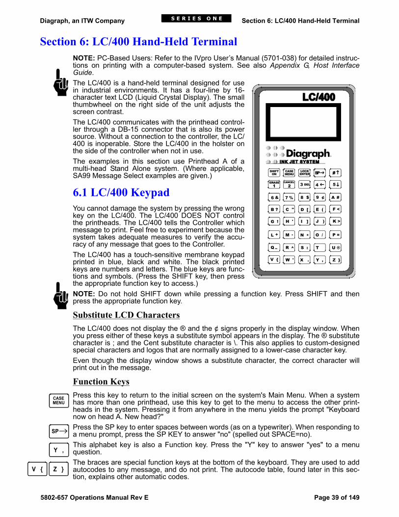
Section 6: LC/400 Hand-Held TerminalNOTE: PC-Based Users: Refer to the IVpro User’s Manual (5701-038) for detailed instruc-tions on printing with a computer-based system. See also Appendix G, Host InterfaceGuide.The LC/400 is a hand-held terminal designed for usein industrial environments. It has a four-line by 16-character text LCD (Liquid Crystal Display). The smallthumbwheel on the right side of the unit adjusts thescreen contrast.The LC/400 communicates with the printhead control-ler through a DB-15 connector that is also its powersource. Without a connection to the controller, the LC/400 is inoperable. Store the LC/400 in the holster onthe side of the controller when not in use.The examples in this section use Printhead A of amulti-head Stand Alone system. (Where applicable,SA99 Message Select examples are given.)
6.1 LC/400 KeypadYou cannot damage the system by pressing the wrongkey on the LC/400. The LC/400 DOES NOT controlthe printheads. The LC/400 tells the Controller whichmessage to print. Feel free to experiment because thesystem takes adequate measures to verify the accu-racy of any message that goes to the Controller.The LC/400 has a touch-sensitive membrane keypadprinted in blue, black and white. The black printedkeys are numbers and letters. The blue keys are func-tions and symbols. (Press the SHIFT key, then pressthe appropriate function key to access.)NOTE: Do not hold SHIFT down while pressing a function key. Press SHIFT and thenpress the appropriate function key.
Substitute LCD CharactersThe LC/400 does not display the ® and the ¢ signs properly in the display window. Whenyou press either of these keys a substitute symbol appears in the display. The ® substitutecharacter is ; and the Cent substitute character is \. This also applies to custom-designedspecial characters and logos that are normally assigned to a lower-case character key. Even though the display window shows a substitute character, the correct character willprint out in the message.
Function KeysPress this key to return to the initial screen on the system's Main Menu. When a systemhas more than one printhead, use this key to get to the menu to access the other print-heads in the system. Pressing it from anywhere in the menu yields the prompt "Keyboardnow on head A. New head?"Press the SP key to enter spaces between words (as on a typewriter). When responding toa menu prompt, press the SP KEY to answer "no" (spelled out SPACE=no).This alphabet key is also a Function key. Press the "Y" key to answer "yes" to a menuquestion. The braces are special function keys at the bottom of the keyboard. They are used to addautocodes to any message, and do not print. The autocode table, found later in this sec-tion, explains other automatic codes.
1 3 4 5
6 7 8 9 ¢ A
B ? C " D [ E ( F <
G ! H ' I ] J ) K >
L M N O / P =
Q R S : T U ®
V { W ' X . Y , Z }
& % #$
+ -
^
SHIFTON SP
*
CASEMENU
LOCKENTER 0
ERASE CANCEL2 DEL
CASEMENU
SP
Y ,
Z }V {

Diagraph, an ITW Company Section 6: LC/400 Hand-Held Terminal
Page 40 of 149 5802-657 Operations Manual Rev E
Shift FunctionsTo enter a lower-case character one time in your label, press SHIFT, CASE, then theappropriate character.Press SHIFT then any of these keys to move through message lines, information state-ments (in the Printhead Status Function) or through several of the functions available in theUtility Menu.
To change the case of a letter key, press SHIFT then LOCK. Locked mode means that allletters in the messages will appear in the display window in their capitalized form. Theprinthead will always print in capital letters although lower case fonts are available uponrequest. The Locked mode does not affect those upper-case characters selected by non-alphabetical character keys such as #, & and so forth. It is best to leave the locked modeengaged to avoid confusion.Press SHIFT then DEL to delete the character immediately to the left of the cursor. Thearrow will then move back to that position.Press SHIFT then ERASE to erase the entire message.Press ENTER to save a message to the Printhead Controller memory or to enter a valueinto a function in the Utility Menu. In the Message Editing Function, press SHIFT then CANCEL to cancel the entire editingsession and return the last message saved to the display window. In the Utility Menu, useCANCEL to move to the next function.
6.2 LC/400 Menu OptionsThe Series 1 system has a Main Menu and a Utility Menu. The Main Menu offers fivechoices:1. Printhead Selection: Keyboard now on head A. New?2. Message Routing: Select msg to print?3. Message Editing: Write or review message?4. Printhead Status: Show printhead status?5. Utility Menu: Utility menu?The Utility Menu has ten functions:1. Change item number?2. Set character width?3. Set character spacing?4. Set font?5. Set indentation? (Available in the SA99 Select system only.)6. Set time?7. Set date?8. Reset printhead?9. Purge valves?10. Change pallet count?Additional special features can add functions to these menus.The five Main Menu choices, identified by their respective prompts, appear in the LCD.To use the system, simply do what the system requests. The system asks for an answer of"yes" or "no", a number, or a message.
SHIFTON
CASEMENU
SP 0 4 5
LOCKENTER
ERASE1
3 DEL
LOCKENTER
CANCEL2

Diagraph, an ITW Company Section 6: LC/400 Hand-Held Terminal
5802-657 Operations Manual Rev E Page 41 of 149
The following section details the functions that are available. The directions and examplesare for multiple printhead systems.
6.3 Selecting a PrintheadAfter turning on the Controller/IDS, you can begin to enter messages into the system withthe LC/400. If the system has two printheads "daisy-chained" together, the LC/400 cancommunicate with both Controller logic boards (which then communicate with both print-heads) in the system. 1. Press MENU (it may be necessary to press it more than once). The display shows:2. Enter the letter of the appropriate printhead.3. Label all printheads and controller boards with letters from A-O. (See "Setting Print-
head Addresses" in Section 5 more information.) The system will automaticallyadvance to the next function in the Main Menu, Message Routing.
Although it is possible to scroll through the various functions using the up and downarrows, the ONLY way to access the function that changes the printheads is by pressingMENU.
6.4 Selecting a Message to PrintThis function enables you to send any stored message to a printhead. Do not use this func-tion until you have created several messages.For the initial startup, answer no by pressing SP when the LCD prompts "Select msg toprint". Advance to the "Write or Review Message" function (see below). Return to this functionwhen you have stored several messages in the controller.Press Y to answer yes when the LCD prompts "Selecting msg to print". Three choices ofaction are possible:1. Press ENTER to print the message number shown on the LCD.2. Press the up and down arrows to view all the messages in the system one at a time,
and press ENTER when the desired message appears on the LCD.3. Type in the number of the message to print and press ENTER.The system verifies that the message was sent successfully and then advances to the nextfunction, Write or Review Message.With the SA99 Message Select system, the print message is selected using the thumb-wheel switches. Simple dial in the message number on the printhead’s corresponding logicboard.
6.5 Writing and Saving a MessageEach logic board on the PHC can store as many as 99 messages. Each message line pro-vides room for up to 40 characters, including spaces between words. Follow these steps tocreate a message:1. Press Y for yes when the LCD prompts "Write or review msg?"2. The LCD will request a new message number. Press SP to select the first available
blank message line or type the message number desired and press ENTER.As an exercise, type in the test message DIAGRAPH SERIES 1 SYSTEM. If you make amistake, use the arrow keys to move the cursor to the immediate right of the mistake andpress DEL. When done, press ENTER to save the message to the controller’s memory.After saving, you will get a chance to change the print values.The expression "print values" refers to the parameters that affect the appearance of thecharacters and messages printed by the Series 1 system: Font, character width and char-

Diagraph, an ITW Company Section 6: LC/400 Hand-Held Terminal
Page 42 of 149 5802-657 Operations Manual Rev E
acter spacing. Font is the type style in which the characters will appear. Character width isthe measurement from dot column to dot column in 1/100s of an inch. Character spacing,the amount of space between characters, in measured in empty dot columns.For every print value, there is a default value that the system uses in printing unless youset an alternate value. The default font is Font #1, a 9-dot high, bold font. The default char-acter width is 0.08" between dot columns. Default character spacing is three dot columns.
Changing Factory DefaultsThe prompt "Change print values?" adjusts the factory-set values for writing or editing amessage. For now, press SP to move past these prompts. (See "Utility Menu Functions"later in this section for more information on these prompts.) To write or review other mes-sages, scroll through the message lines using the up and down arrows.
6.6 Editing a MessageYou will now change DIAGRAPH SERIES 1 SYSTEM to DIAGRAPH SERIES 1 INK JETSYSTEM with appended date and time autocodes.1. Press MENU to return to the top of the Main Menu and then scroll through the functions
until the "Write or review msg" prompt appears.2. Press Y to access edit function.3. Type the message number to edit and press ENTER. For this example, use the right
arrow to move the cursor to highlight the initial S in SYSTEM and type INK JET fol-lowed by a space. Use DEL to correct errors. Enter the autocodes for time {T} and date{D} at the end of the message. Be sure to insert a space between the autocodes.
4. Press ENTER. The LCD will ask if you want to change values.5. As in the previous example, accept the factory-set values by pressing SP to answer no
and complete the edit.After saving, the LCD returns to the edited message. After creating or editing a messageline, use the scroll keys to review the other message lines, or press MENU to return to thetop of the Main Menu. From there, proceed to other functions by pressing SP.
6.7 AutocodesAutocodes are codes used to print various configurations of time, date, numeric sequenceand font selection. Place all autocodes within the braces {} found in the lower corners of theLC/400 keyboard. Autocodes are not case sensitive.Some autocodes print their messages in familiar forms such as the date as a six-digit figureor the time on a twenty-four hour clock. Other autocodes print their messages in code withthe month as a single letter (A through L) or the hour as two digits (00-23). This allows youto print more information in the same amount of space. Used properly, these codes can bea powerful tool for tracking production and inventory.While it is possible to enter more than one autocode in the same set of braces, it is best toleave a space between them to save confusion. For example, {DN} will print 03/25/96748,while {D N} will print 03/25/96 748.To enter a symbol that is not one of the autocodes, for example a # symbol, enter it before,between or after the commands in the braces. {D} #{N} will print 03/25/96 #748. Again,leave a space so that the characters do not run together.
Autocode FormatsDate Codes: Autocodes offer eight different formats for printing the date:
D Full conventional date: six digits plus slashes (month/day/year: 01/01/00)

Diagraph, an ITW Company Section 6: LC/400 Hand-Held Terminal
5802-657 Operations Manual Rev E Page 43 of 149
J Julian Date: the numeric day of the year. Three digits, 001-366 (001 = January 1)M Month only. Two digits, 01-12.A Day of the month only. Two digits, 01-31.I Dayof the year as two letters, AA-OBL Month only as a single letter, A-LB Day of the month as a single character: 1-9 signifies the first through the ninth and A-
V is the tenth through the thirty-first. Y Year as two digits: 99
Time Codes: Autocodes offer four different formats for printing time:T Time as reported by a 24-hour clock, four digits plus colon: 00:00H Hour only, two digit: 00-23G Hour as a single letter: A-X (the day starts at midnight)Q Time in 15-minute intervals as two numbers, 00-95
Font Selection: Autocodes offer six different fonts: {F#} where # is 1-61 Nine-dot tall bold, proportional2 Nine-dot tall single, proportional3 Seven-dot tall single, proportional4 Seven-dot tall single, fixed width5 Top half, 18-dot tall proportional6 Bottom half, 18-dot tall proportional
Number Sequence: Autocodes offer two ways to count items:N Number sequence from 1 to 999999P Pallet count
Using the Number Sequence CodeUse this autocode to print sequential numbers from 1 to 999999 or any subset with asmaller upper limit. When the counter reaches the top of the sequence, it automaticallyresets and starts again with 1. The Item Counter runs whenever the controller is turned on.1. Reset the Item Counter (change Item Number function under the Utility Menu) before
beginning with a new sequence.2. Check the TOTAL of the Item Counter by pressing Y at the "Check Printhead Status?"
prompt. The LCD will then display a status screen. At the beginning of the second lineof this screen, you will see "Total=" and a number. That number is the number of thenext item to pass in front of the photosensor.
3. To reset the Item Counter, use the Change Item Number function in the Utility Menu.The Item Counter will always reset and start printing with 1, so it makes sense to startwith 1 for a consistent sequence.
Creating an Upper Limit SequenceTo define the upper limit, choose the maximum number of items you want to pass in front ofthe photocell before the counter resets. Enter this number immediately after the N insidethe braces ({}). {N10000} would run a sequence from 00001 to 10000; {N99} would runfrom 01 to 99.

Diagraph, an ITW Company Section 6: LC/400 Hand-Held Terminal
Page 44 of 149 5802-657 Operations Manual Rev E
When you set an upper limit inside the braces, the system will print zeros for unfilledspaces. For example, if you set your upper limit at 999 {N999}, the label for the ninth itemwill print as "009" and the label for the ninety-ninth as "099". The basic {N} command doesnot include these zeros and the numbers appear as 1, 2, 3..., 454, 455, and so on.While {N99} will print 01 through 99 and then restart the counter at 01, {N00} is a specialcase that will print 00 through 99, then 00, 01, etc. Print 0 to 9, 00 to 99, and so on by enter-ing the zeros (0, 00, 000, 0000) as the upper limit. However, use the Change Item NumberFunction to make the first sequence start at 0.A 40-character message is the limit on the LC/400 screen. However, the autocode com-mands can make the printed message run longer. With these commands, the actual lengthof the message can expand to as many as 60 characters. The message "Product ID#:" witha time, date and sequence from 1 to 999999 would read "Product ID#: {T D N}" on the ter-minal and would be 20 characters long. When printed, though, the message would be 32 characters long and read: "Product ID#:15:40 03/25/93 1079," 32 characters long. To see the message, scroll the Current Messageline of the Show Printhead Status Function using the left and right arrow keys.
Using the Pallet Count CodePallet count coding splits the one-to-six-digit item number into two sections, pallet countand item count. The pallet count increases by one every time the item count reaches thepre-set limit. You are telling the Controller that each pallet will contain a certain number ofitems; after reaching that number, start a new pallet.The basic command to print a pallet count is {P}. Follow the "P" with a one-to-five digitnumber that specifies the number of units per pallet {P25}. In this case, the target itemprints with a pallet number of "1" until 25 items are printed. Item 26 will print with a palletcount of "2".Use code {N} to include an item count in the Pallet Count Code. When used in a PalletCount Code, this will print the pallet count and the item number within that pallet. Whenusing both of these codes, follow each by the same limit value {P25N25}.The pallet count and the item count together can never be longer than six digits. The itemcount limit determines how many digits can be in each count. For example, {P25N25} hasthe unit count of the pallet set at two digits (upper limit set to 25) and the pallet count set upto four digits (possible upper limit 9999).Note that the upper limit set in the pallet code is the number of units within the pallet, notthe number of pallets to be marked. The number of items within the pallet sets the bench-mark for the pallet count. Setting the pallet count at 25 results in pallet 1 containing the first25 items, pallet 2 containing the next 25 items and so on.When you reset the system, it starts at pallet 1, item 1. To start at pallet 1, item 1 or anyother value, use the "Change Item Number" function explained later in this section.Within the "Change Item Number" function, the pallet count is the first part of the numbershown and the item count is the last part. For example, if the code currently in use is{P25N25} and the pallet number currently printing is 16, item 3; the item number shown willbe 1603. In the same example, to reset both the pallet and item counts to 1, set the itemnumber at 101.
Font Selection Code (Using 9-dot Fonts)Each Controller has the capacity to print several different fonts. You can select any fontfrom the options available for use in each message. If you do not designate a specific font,the system uses the default font of F1 (a 9-dot tall bold font). You can instruct the Controllerlogic boards to change fonts within a message by including the appropriate font code withina pair of braces.The font selection code is {Fn} where "n" is the number of the code corresponding to thefont desired. For example, to print a message using fonts 2 and 3, enter the following:

Diagraph, an ITW Company Section 6: LC/400 Hand-Held Terminal
5802-657 Operations Manual Rev E Page 45 of 149
DIAGRAPH SERIES 1 {F2} INK JET {F3} SYSTEMThe message begins in the font selected in the "Change print values" function of the utilitymenu, so the printhead would print "DIAGRAPH SERIES 1" in font 1. "INK JET" would bein font 2. "SYSTEM" would appear in font 3.The message will come out the same whether the printhead is printing right-to-left or left-to-right. The new font applies to the text following the {Fn} code as you read the message,regardless of the printing sequence.
Font Selection Code (Using 18-dot Fonts)The system can print an 18-dot tall font using either an 18-dot printhead or two 9-dot print-heads. The system requires two separate fonts to do this: the upper half of an 18-dot pro-portional font (font number 5) and the lower half of an 18-dot proportional font (number 6). To accomplish this send two messages, with exactly the same text, from the controller tothe 18-dot printhead or to the two 9-dot printheads. Both printheads must have the samecharacter width and spacing. The first printhead prints the upper half or top nine dots of thefont and the other printhead prints the lower half or bottom nine dots of the font. You canalso include standard autocodes in your message.Mixing 18-dot characters within a message:You can mix 9-dot and 18-dot characters within a message, if you follow a few simpleguidelines.When printing either 7-dot-high or 9-dot-high text on the same message line as 18-dot-hightext, use a fixed-width font to print the 7-dot or 9-dot text.Special cases include, printing the 7- or 9-dot text to the left of the 18-dot text when printingleft to right or printing the 7- or 9-dot text to the right of the 18-dot text when printing right toleft. Both printheads must use the same fixed-width font and they must print the same num-ber of characters before the 18-dot text. Codes enclosed in braces producing a fixed num-ber of characters are allowed. Once the system prints all of the 18-dot tall text in a message, the rest of the message canprint using proportional fonts. When printing two lines of text followed by one line of 18-dottall text, do not use the 9-dot fonts because there will be no space between the two lines.Instead, use two 7-dot fixed-width fonts to leave a space between the two lines of text. Usethe 9-dot fixed-width font only if one line of 9-dot tall text is being printed. In such a case,send a message containing all spaces in the same 9-dot fixed-width font to the other sec-tion of the 18-dot printhead. The key is that both 9-dot sections of the 18-dot printheadmust have the same number of characters (including spaces) in their message lines.Printing 18-dot time and date codes may be a bit more complicated, as it is difficult to syn-chronize the clocks in the two Logic boards. Although the clocks are quite accurate, theycan run slightly slow or fast, so the time may not be exactly the same for the two print-heads.NOTE: For PC-based systems, additional autocodes are available. Information on these isavailable with the IVpro software that ships with the PC-based system.
The Variable Field PromptThis autocode, entered as {Z}, prompts the operator to input variable data before a mes-sage prints. The prompt has a maximum character length of 30, including the Z. (Example:{Z Enter Part Number})
The Weight CodeUse this code to insert any value into your message via the serial port from an externaldevice, such as a scanner or a scale. There are two variations of this autocode:• RW: Inserts external data read through a COM port into a message• RL: Inserts external data read through a COM port into a messageExample: <STX>RW<data><CR> or <STX>RL<data><CR>

Diagraph, an ITW Company Section 6: LC/400 Hand-Held Terminal
Page 46 of 149 5802-657 Operations Manual Rev E
These autocodes only read data preceded by "RW" or "RL". Be sure to turn ON the Exter-nal Data option under the Print Menu and select the correct COM port under the SetupMenu.
Special Expiration Date Code {K}This autocode shows the expiration date in the following format:{K 01 2002 08 2} • K = autocode• 01 = month• 2002 = year• 08 = number of years in the cycle• 2 = sets digit limits in month
6.8 Checking Printhead StatusThe Printhead Status Function provides information on the operational status of each print-head. This function shows three reporting screens: the Summary screen, the Current Sta-tus screen and the Current Message screen.1. Access this function by pressing SHIFT followed by the up arrow until the LCD prompts
"Show printhead status?"2. Press Y to answer yes.The first line of the summary screen shows the number of messages printed per minute(calculated every 15 seconds as a running average).The second line is the total number of items printed since the current message began print-ing. The second section of the line reads "All OK" when the system is operating properly.This section also provides warnings for conditions that require attention and could show"WARNING" or "ERROR". The Current Status screen explains the conditions indicated. Press the down arrow to move to the Current Status screen.
Status MessagesThe Current Status screen shows the message number currently being printed, the fontused and the status of the printhead. The letter of the printhead precedes the message.Some status messages are error or warning conditions, while others are merely informa-tional.Line stopped indicates that the controller is no longer receiving speed information from theencoder.Purging indicates that the valves are currently purging on a command from the operator. Aburst of ink or conditioner is being ejected through all orifices.Printing indicates that the printhead is currently printing a message.Bad msg indicates that there is no message stored on the message line selected for thisprinthead, or that the stored message contains a bad autocode.Standing by indicates that the printhead is not currently printing, but is ready to print. Thisreport can also appear with Line stopped, meaning that although the line has stopped, theprinthead is standing by ready to print.Error time (and item number): After any error message, the LCD window shows the time ofday the error occurred and the item count at the time of the error. Compare the number onthe current status line to the "Total" number on the Summary line to show how many itemshave passed since the error occurred.Msg advanced means that the Message Advance button on the controller has beenpressed.

Diagraph, an ITW Company Section 6: LC/400 Hand-Held Terminal
5802-657 Operations Manual Rev E Page 47 of 149
If the current status line indicates more than one of these conditions at the same time, youwill see that the message extends beyond the 40-character limit of the display window. Ifso, a small arrow indicates the direction (right or left) in which the message continues. Usethe appropriate arrow key on the keyboard to move in the direction of the arrow. Notice thatthe cursor will move not from one character to the next, but from one status entry to thenext.Press the down arrow to move to the third Printhead Status information screen, the CurrentMessage screen. The message currently being printed will appear in the display window.Scroll the Current Message line (Show Printhead Status) to the left and right to accommo-date any added length message. Using the arrow keys, you can scroll horizontally to readthe entire message as it appears when printed. You will not see this message if the print-head is disabled or not being used.When you have finished reviewing the Printhead Status screens, press the MENU key. Thiskey releases the Printhead Status function and returns you to the Main Menu.
6.9 The Utility MenuPress SP to scan the various functions, which appear as questions:• Change item number?• Set character width?• Set character spacing?• Set font?• Set indentation?• Set time?• Set date?• Reset printhead?• Purge valves?• Change pallet count?Set Indentation is available on the SA99 Message Select system only. On the SA99 model,use the thumbwheel switches on the logic boards to set the indentation. The SA-99 Mes-sage Select reserves the thumbwheel switches for selecting messages to print.Enter a function by pressing Y on the keyboard to answer Yes. Once you access a func-tion, use the up and down arrows to advance to the next or previous function. However, inthe case of the "print value" functions (Set character width? and Set character spacing?),use the arrow keys to scroll through the print values of all stored messages. Press CAN-CEL twice to reach the next function in the menu. Pressing MENU will always advance youto the first prompt in the Main Menu.
Change Item NumberThis function resets sequential numbering in labels to any number (up to 999999). Accessthis function by pressing the SHIFT key followed by the up arrow key until the displayprompts for the Utility Menu. Answer yes and Change Item Number? will appear. Press Yand the LCD will show Next item # now=1. New #? Type a new number and press ENTER.This number becomes the next number that will print. The LCD will flash this new numberand advance to the next function in the Utility Menu.
Set Character WidthThe character width is preset at 8 (.08 inch from the beginning of one dot column to thebeginning of the next dot column). This setting produces an attractive, well-proportionedcharacter. Use this function if you need condensed or elongated characters. To set character width, increase or decrease the width of the dot columns in one-hun-dredth-of-an-inch increments. The available range is from.02 inches per column to.25inches per column.

Diagraph, an ITW Company Section 6: LC/400 Hand-Held Terminal
Page 48 of 149 5802-657 Operations Manual Rev E
The LCD will prompt A: Set character width? Y=yes SPACE=no. Press Y and LCD will askfor a message number from 1 to 99. Type a number and press ENTER. The LCD will showthe printhead letter, the message number and the current column width setting.If you have not changed column width, the preset value of 8 will appear. Type in a new col-umn width and press ENTER. The system will automatically enter the decimal point.WARNING: Do not set the value of the minimum character width less than the value thatwill cause the printhead frequency to exceed 1000 Hz. (See Appendix F: Maximum dpi Cal-culation for a Given Line Speed.)If you are changing the column width of the message currently printing, the LCD will remindyou that the designated message is being printed. This reminder appears because chang-ing the column width now will alter the appearance of the message currently printing.To cancel the command, press SP. The system will return to the "Column width now=W"prompt to provide another opportunity to change widths.Use the arrow keys to view the Character Width settings for the other message lines. If amessage line is empty "No message number M" will appear. Press CANCEL to advance tothe next function on the Utility Menu, Set character spacing? Keep in mind that if you entera value less than 2 or greater than 26, a reminder screen will appear.
Set Character SpacingCharacter spacing is the amount of blank space between individual characters measuredin dot columns. The pre-set character spacing value is three empty dot columns. To changecharacter spacing, use this function. The available range is 0-19 dot columns.After pressing CANCEL, the LCD will prompt A: Set character spacing? Y=yes.SPACE=no. Press Y and the LCD will ask for a message number from 1 to 99. Type in themessage number, and the LCD will display the printhead, the message number and thecurrent character (abbreviated "char") spacing. If you have not changed the column spac-ing, the default value of 3 columns will appear.Enter the new character spacing value from 0 to 19. For example, if you type 2 and pressENTER, the LCD will flash and display spacing now=2cols.If you are changing the character spacing of the message currently printing, the LCD willremind you that the designated message is being printed. This is because changing thecharacter spacing now will alter the appearance of the message currently printing. To can-cel the command, press SP. The system will return to the Character spacing now= promptto provide another opportunity to change the spacing.to continue with the new spacing of 2, press Y and the LCD will show char spacingnow=2cols. This screen also allows access to other messages in the logic board for thisprinthead. Use the scroll keys to view the Character Spacing settings for the other mes-sage lines.Press SHIFT then CANCEL to advance to the next function on the Utility Menu.
Font ChoicesTable 6 shows the six fonts available on the Series 1 System.
Table 8: Series 1 Fonts
Font No.
Description Use
1 9-dot BOLD Proportional font closes up unused space around smallercharacters.
2 9-dot Single Proportional font closes up unused space around smallercharacters.
!

Diagraph, an ITW Company Section 6: LC/400 Hand-Held Terminal
5802-657 Operations Manual Rev E Page 49 of 149
"Fixed Width" refers to a font in which each character occupies the same amount of hori-zontal space. A narrow character such as I occupies the same amount of space as a widercharacter such as W. In contrast, a proportional font allots only as much horizontal spaceas is dictated by the shape of each character; an I occupies far less horizontal space than aW.
Selecting a FontScroll through the Utility to Set a Font? Press Y for yes and the LCD will prompt for a mes-sage number from 1-99. Type the number and press ENTER. The LCD will display theprinthead, the message number and the number of the current font. (If a font has not beendesignated, the preset value of 1 will be displayed.Type the desired font number and press ENTER. If the chosen message is currently print-ing, the LCD will remind you that you are making a change midstream. If press Y the nextcarton will reflect the change. To cancel the change, press SP and the system will return tothe screen that reports the current font number.If Y was pressed, or if the message chosen was not printing, the LCD will show the newlyassigned font on screen.Use the arrow keys to view the font settings of the other messages stored on the logicboard, or press CANCEL to move to the next Utility Menu function.
Set TimeTo reset the logic board’s internal clock, scroll to Set time? and press Y; the LCD will dis-play the current time and prompt for entry of a new one. Type a new time such as 1000(colon is automatically inserted) and press ENTER. The LCD will briefly show the new set-ting and then advance to the Set date? function.
Set DateAt the Set date? prompt, answer Y and the current date will be displayed. Type the newdate. (For June 15, 2002, type 061502; slashes are inserted automatically.) The LCD willbriefly flash the new date and then advance to the Reset printhead? function.
Reset PrintheadThis is a service function that restarts a printhead disconnected by a communication error.At the Reset printhead? prompt, press Y, then Y again to confirm, or SP for no. The systemwill advance to the Purge valves? function.
3 7-dot Single Proportional font closes up unused space around smallercharacters.
4 7-dotFixed Width
Used primarily for messages that mix 7-dot characters with18-dot characters. Produces a 7-dot tall, single dot characterwith fixed characters at 5 columns wide.
5 18-dot Upper Forms the upper 9 dots of an 18-dot proportional character.Must be used with Font 6.
6 18-dot Lower Forms the lower 9 dots of an 18-dot proportional character.Must be used with Font 5.
Table 8: Series 1 Fonts
Font No.
Description Use

Diagraph, an ITW Company Section 6: LC/400 Hand-Held Terminal
Page 50 of 149 5802-657 Operations Manual Rev E
Purge ValvesThe difference between purging through this menu and pressing the Purge button on thelogic board is that this function purges only the designated printhead; the logic board buttonwill simultaneously purge all the heads connected to that board, provided each head’sStop/Run switch is turned ON.At the Purge valves? prompt, press Y, then Y again to confirm. Be sure to hold an absor-bent cloth against the faceplate of the printhead to soak up the ink. While purging, the LCDwill report "Purging Valves". When finished, it will ask if you want to purge again. Press Y topurge again, or SP to advance to the Change pallet count? function.
Change Pallet CountThis function allows you to change the pallet count value if you need to remove a pallet forsome reason. For example, if you are currently printing items with pallet number five onthem and you notice a quality problem with all the items on that pallet, you can restart thecurrent pallet at number five even though six is the next sequential pallet number.At Change pallet count?, press Y. The LCD will display the current pallet and prompt for anew value. Type the new number and press ENTER.
Set Indentation (SA99 Select System Only)This function appears only in systems with SA99 Message Select boards installed. At Set indentation?, press Y to set the start indentation, or the distance from the edge ofthe product to the start of the printed message. The current indentation is displayed in hun-dredths of inches, without the decimal point (455=4.55"). Enter a new value and pressENTER. The LCD reports your new indentation value and asks, Continuous (web) print? To printonce per product, press SP for no. The LCD will confirm your choice (Continuous (web)print is OFF) and exit to the Set time? function.To print in web mode, press Y. The LCD will confirm your choice and show the current mes-sage’s repeat distance, or the distance between the first character of one message to thefirst character of the next message. For example, a message that is 6 inches long, printingin web mode with a repeat distance of 14 inches, will have 8 inches of open space betweenmessages. To ensure that all message lines begin printing at the same time on a printstation with mul-tiple printheads, set all heads on the printstation to the same repeat distance.To change the repeat distance, enter the new value without a decimal and press ENTER.The LCD will flash confirmation of the new value and exit to the Set time? function.
6.10 Special OptionsWith the development of new system capabilities, new versions of firmware are releasedwith these features available to all customers. Before you begin configuring the setup,decide which capabilities you want. Once this is decided, calculate the Total Option Valueto tell the software which options to enable. Use DIP Switch 4 on the Printhead ControllerLogic Board to enter the calculated value for the OPTION VALUE. After entering the TotalOption Value, no changes are necessary unless different options are needed. The following chart shows the eight special options available, and at what level the capabil-ities were introduced. Any level at or above the noted version will have the capability avail-able. For example, to use Capability Number Sixteen for Thumbwheel Message SelectionActive, use firmware version V3.5 or above.When ordering new firmware, be sure to get the latest version available. Note that Versions3.3 and up use delays entered through the keyboard rather than the thumbwheel switches,so if thumbwheel delays are necessary, you need to order the latest version below V3.3. If

Diagraph, an ITW Company Section 6: LC/400 Hand-Held Terminal
5802-657 Operations Manual Rev E Page 51 of 149
higher level capabilities are not desired, you do not need to enable them (If using customfirmware, be sure it has the required capabilities for your needs.).
Setting the Option Value is a four-step process:1. Decide which options you want (and what your firmware can support).2. Calculate the Total Option Value by adding the individual Option Values of selected
options. (This tells the software which functions to enable.)3. Set DIP Switch #4 on each logic board.4. Enter the appropriate Option Value via the LC/400.
European/Canadian DateLeave this option OFF to use American dating (MM/DD/YY). Turn ON to select Canadian/European dating (DD/MM/YY).
One Consecutive CountTurn ON to maintain a consecutive count even after changing messages. Leave OFF tohave the count reset each time a new message is selected.
Disable Message AdvanceTurning this option ON prevents accidental message changes by disabling the messageadvance button located on the interface board inside the Controller/IDS.
Individual Message CountsThis option keeps individual message counts. Turn on to keep a separate count for eachmessage. The count is preserved even when the system power is off.
Thumbwheel Message Selection ActiveThis allows for message selection with the thumbwheel switches located on the logicboards inside the controller, bypassing the LC/400.
Table 9: Special Options
FirmwareVersion
Special Option OptionValue
3.2 European/Canadian Date 1
3.2 One Consecutive Count 2
3.2 Disable Message Advance 4
3.4 Individual Message Counts 8
3.5 Thumbwheel Message Selection Active 16
3.6 Reset Count to 1 at Power Up or Hardware Reset 32
3.633.22
Mirror-image Print or Lower Half of 18-dot Printhead 64
3.67 Enables Bar Code Printing 128
Sum of Desired Option Values = TOTAL OPTION VALUE

Diagraph, an ITW Company Section 6: LC/400 Hand-Held Terminal
Page 52 of 149 5802-657 Operations Manual Rev E
Reset Count to 1 at Power Up or Hardware ResetThis option allows the user to reset the count to 1 by turning on the power or pressing thelogic board reset button.
Mirror-Image Print or Lower Half of 1-inch 18-dot PrintheadThis option enables printing a mirror-image font, and must be on to enable normal printingwith the lower half of the 1-inch 18-dot printhead.
Relationship of Special Item Number OptionsSpecial options 2, 8 and 32 affect the item number. Note that when option 8 is ON, it dis-ables options 2 and 32. The table below shows how these three special options can beused together for special applications.
Entering the Total Option ValueAfter deciding which special options are needed for your application, add up the individualoption values to get the Total Option Value. Use the following procedure to set this value fora single printhead system:1. Turn the controller/IDS OFF.2. Push DIP Switch 4 to the ON (Closed) position.3. Turn the controller/IDS ON. When the introductory screen appears, push any key.4. At the LCD prompt (option = #), enter the Total Option Value and press ENTER. The
screen will display the new option value.5. Turn the controller off. Push DIP Switch 4 to OFF.6. Turn the controller ON to resume normal operation.
Table 10: Special Item Number Options
SpecialOption 8
Ind. Count
SpecialOption 32
Reset Countto 1
SpecialOption 2Consecu-
tiveCount
Result
OFF OFF OFF One count, remembered even when poweris OFF. Resets to 1 when messagechanges.
OFF OFF ON One count, remembered even when poweris OFF. Does not reset when messagechanges.
OFF ON OFF One count, resets to 1 when power is OFF.Resets to one when message changes.
OFF ON ON One count, resets to 1 when power is OFF.Does not reset when message changes.
ON ON or OFF ON or OFF Individual Message Counts rememberedeven when power is OFF. Reverts to Mes-sage Count for new message when mes-sage changes.

Diagraph, an ITW Company Section 6: LC/400 Hand-Held Terminal
5802-657 Operations Manual Rev E Page 53 of 149
NOTE: Each printhead logic board has its own Option Value. Use the following procedurefor a multiple head system:1. Turn off all controllers.2. Push DIP Switch 4 to ON for each logic board in the system.3. Turn all controllers ON.4. Press MENU to display: Keyboard now on head A. New head?5. Enter the letter for the new head address, and press ENTER.6. Press the left arrow key to display the option = # prompt. Enter the desired Option
Value and press ENTER. The screen will display the new value.7. Repeat this for each head in the system.8. Turn off all controllers.9. Turn DIP Switch 4 OFF on every logic board.10. Turn the controllers ON to resume normal operation.
Determining Which Options Are Already SetIf you want to add a special option without losing any of the special options already set, youmust first determine which options have been turned on. This can be done as follows:1. Determine the highest Option Value that is lower than the Total Option Value shown on
the LCD; this option value is among those set. (For example, if the Total Option Value is73, 64 is one of the values selected.)
2. Subtract this option value from the total. 3. Repeat steps 1 and 2 until the result equals 0. Any values that were subtracted were for
options that were ON. Any other options were OFF.EXAMPLE: You wish to add Option 2. • The Total Option Value is shown as 77. The highest Option Value lower than this is 64*.
Subtract this from 77.• 77 - 64 = 13. The highest Option Value lower than this is 8*. Subtract this from 13.• 13- 8 = 5. The highest Option Value lower than this is 4*. Subtract it.• 5 - 4 - 1*. Subtract it.
*All the values that were subtracted represent options currently turned ON in your con-figuration. You now know that Option 2 is not one of them. In order to add it, just add 2to the number shown, and enter a new Total Option Value of 79.

Diagraph, an ITW Company Section 6: LC/400 Hand-Held Terminal
Page 54 of 149 5802-657 Operations Manual Rev E

Diagraph, an ITW Company Section 7: Maintenance
5802-657 Operations Manual Rev E Page 55 of 149
Section 7: MaintenanceThe following maintenance procedures are recommended for clean and efficient operation.
7.1 Controller MaintenanceDaily Start UpBe sure no cables or electrical cords are tangled or damaged before operation.
Daily ShutdownTurn off electrical power to system.
Intermittent (As Required)1. Be sure the photosensor is clean and free of debris.2. Be sure the O-rings (1900-001) on the encoder wheel are present and not worn.3. Be sure the nuts and bolts holding the bracketry in place remain tight.4. Equipment may be cleaned utilizing the appropriate conditioner for the ink in use.
AnnuallyReplace encoder O-rings.
7.2 Printhead MaintenanceWear safety goggles when working with industrial inks or solutions.
Overnight ShutdownShut off all power to the system.
Overnight Startup• Clean the printhead faceplates.
Spray conditioner on a lint-free wipeand wipe the faceplate in a circularmotion to remove ink that has leakedfrom the orifices overnight.
• Purge with ink.To prevent printhead clogging, purgethe printheads by pressing the Purgebutton on the printhead controller.
CAUTION: Pushing the Purge buttoncauses all printheads to purge simulta-neously, so be prepared to catch the ink.
PURGEBUTTON
!

Diagraph, an ITW Company Section 7: Maintenance
Page 56 of 149 5802-657 Operations Manual Rev E
Shutdowns of Seven Days or LongerFlush and thoroughly purge the printhead(s) as follows:1. Begin with the last printhead in the system (the one just before the effluent bottle). To
prevent ink drips, enclose the couplings in a clean cloth when changing connections.Have a cloth handy to wipe up any ink spills.
2. Disconnect the ink line from the female quick disconnect (upper fitting) on the back ofthe printhead, and attach the Flush Bottle assembly (1902-694).
3. Close the shutoff valve and disconnect the effluent bottle assembly from the male quickdisconnect that terminates the ink-feed line to the printheads.
4. Attach the effluent bottle to the effluent port’s male quick disconnect (the lower fitting)on the back of the printhead, and open the shutoff valve.
5. Squeeze the flush bottle to force conditioner through the printhead. Note the color ofthe liquid in the waste line, and continue flushing until it runs clear.
6. Close the shutoff valve and disconnect the effluent bottle and flush bottle assemblies.7. Re-attach the ink line to the printhead.8. Repeat steps 2 through 7 for each printhead in the system. (When starting up again,
you will need to purge each printhead until ink is again flowing to the orifices.)NOTE: Store the effluent bottle where it cannot be knocked over, punctured or damaged.When the effluent bottle is full, dispose of the waste in accordance with local, state and fed-eral regulations.
If You Purchased Spare PrintheadsDiagraph recommends that spare printheads be circulated into operation on a regularbasis. Rotate the printheads every couple of months to keep them performing up to expec-tations. Rotating spare printheads prevents hardening of the internal printhead compo-nents, making startup much easier. Before returning a spare printhead to the shelf, be sureto thoroughly flush it with conditioner.
Effluent Bottle
FlushBottle
FLUSHING THE PRINTHEAD

Diagraph, an ITW Company Section 7: Maintenance
5802-657 Operations Manual Rev E Page 57 of 149
7.3 Ink Delivery System MaintenanceDaily StartupBe sure ink lines are undamaged and free of entanglement in equipment before operation.
Daily ShutdownTurn off electrical power to system.
Intermittent (As Required)When disconnecting ink lines, spray the quick disconnects with the appropriate conditionerto prevent them from sticking open.If the system ink pressure does not build up, and the pump will not run automatically, followthe steps below:1. Be sure there is ink in the container.2. If there is no ink, replace the ink container with a fresh one.3. If there is ink, connect an effluent bottle to the end of the ink line near the printheads
and close the shutoff valve.4. Press and hold the prime button located on the front of the controller/IDS.5. Your should hear the pump running. Now open the shutoff valve and disconnect the
effluent bottle. Hold the prime button until pressure builds up to normal, then release it.
AnnuallyReplace the ink filter assembly (5700-026).CAUTION: To prevent electric shock, turn power OFF at the source.1. Open the front door of the controller and unplug the power cable.2. Disconnect the old filter assembly at its quick disconnects.3. Discard the old filter in accordance with plant safety specifications.4. Connect the new filter by pushing the ink lines into the quick disconnects. Be sure the
arrow on the filter is facing toward the front of the IDS.CAUTION: Ink is under pressure within the ink delivery system and ink lines; be sure tobleed the pressure from the system prior to removing any components.
General Notes On IDS MaintenanceWhen removing components, it is easiest to cut the attached ink line in the center, andremove the tube from the barb after the component is removed.When cutting ink lines within the IDS, it is recommended to place towels on the IDS bottomplate to soak up any residual ink that comes out of the line.Any ink line that is cut in order to remove a component must be replaced; do not attempt toreuse tubing that has been removed from the IDS. REMOVING INK LINES FROM BARBED FITTINGS: From the top of the fitting, pinch thetubing away from the barb with diagonal cutters, then cut. Any nick or scratch on the barbwill result in leakage. (In most cases it is easier to replace the barbed fittings rather thantake a chance that the old fittings will leak due to damage to the barb.)Be sure that tubing is cut square prior to inserting the barb. Failure to insert the barb fullyinto tubing can result in leakage or failure of the barb-to-tube connection.After repairs are complete, operate the IDS and check for leaks prior to returning system toservice.

Diagraph, an ITW Company Section 7: Maintenance
Page 58 of 149 5802-657 Operations Manual Rev E
7.4 Diagnosis and Repair of Contaminated Ink Delivery Systems
The ink delivery system in your Series 1 controller was shipped for use with either Dia-graph TWP (waterbased) or TSO (solvent-based) inks. Do not attempt to switch from onetype to another. Introduction of TSO ink or conditioner to a system that has been runningTWP will create a granular gel-like substance similar to toothpaste. The degree of contami-nation caused will depend on the amount of fluid mixed and how much time it has been inthe system.This procedure covers the diagnosis and repair of system components that are contami-nated or suspected to be contaminated.TOOLS AND SUPPLIES REQUIRED:• Effluent Bottle (5700-994)• Ink Pressure Gauge (5700-743)• Flat head screwdriver• Solenoid Adjustment Tool (1901-388)• Broach• ConditionerFirst, remove the contaminated ink container and replace it with the proper conditioner,then proceed as follows:1. Disconnect ink regulators from the ink lines.2. Open shutoff valve to effluent bottle.3. Flush conditioner through IDS and ink lines until it runs fairly clear.4. Disconnect effluent bottle from end of ink line.5. It is recommended that you change ink lines at this point.6. Connect first printhead regulator to ink line.7. Connect effluent bottle to ink exit port on first printhead.8. Flush conditioner through printhead until it runs fairly clear.9. Disconnect effluent bottle from printhead, and purge printhead 4 or 5 times.10. Repeat steps 6 through 9 for each additional printhead.
Ink Regulator MaintenanceIf print dot size is fluctuating, check the printhead pressure. If the dot size fluctuations canbe correlated to changes in ink pressure, the ink regulator may be in need of service. Dotdiameters will decrease if the regulator input pressure is less than 2.0 PSIG greater thanthe printhead pressure. Prior to performing regulator maintenance, check that the ink regu-lator input pressure is at least 2.0 PSIG greater than printhead pressure. This can bechecked by plugging the ink pressure gauge into the male quick disconnect located in theink line below the regulator.Decreases in pressure can also be caused by obstructions in the valve seat of the ink reg-ulator. Obstructions in the valve seat may cause the pressure to creep up over a 15-minutetime period. For example, the pressure is set at 6 PSIG, and 15 minutes later it hasincreased to 7 PSIG.The following maintenance procedure can remove obstructions from the valve seat area ofthe ink regulator, restoring normal operation. (Ink may be used, but conditioner is recom-mended for this procedure.)1. Unplug the ink regulator from the printhead.2. Plug the regulator output into the effluent bottle.3. Rotate the pressure adjustment clockwise until it stops, then counter-clockwise until it
stops. Repeat six to twelve times.

Diagraph, an ITW Company Section 7: Maintenance
5802-657 Operations Manual Rev E Page 59 of 149
NOTE: Monitor the fluid level in the effluent bottle to ensure that it does not overflowduring this procedure.
4. Turn the ink regulator off (completely counter-clockwise) and connect it to the print-head.
5. Connect the pressure gauge to the printhead ink exit port.6. Turn the regulator up to the specified pressure.7. Monitor ink pressure while printing. Note that the pressure can drop by as much as 0.75
PSIG (usually less) during the print cycle.8. Increase the ink pressure such that the nominal printhead pressure is centered within
the deflection of the gauge while printing.9. Check pressure 15 minutes after setting it. The pressure should be within the same
range ± 0.5 PSIG. If not, repeat the procedure. If the regulator exhibits pressurechanges after performing this procedure two times, the regulator should be replaced.
7.5 Printhead Failure and FlushingPrinthead failure appears as orifice seeping or leakage from contaminant that is trappedbetween the membrane and the post. This contaminant block creates a path for ink seep-age. If the contaminant escapes this area, it usually clogs an orifice, and causes off-targetprinting or obstructs the orifice completely. When printhead failure is observed, flush thesystem as follows:1. Plug the effluent bottle into the fluid exit port of the printhead and allow ink to flow for
about two minutes while purging the printhead. Unplug the bottle to stop the flow.2. Purge the printhead 3 to 5 times.3. Pour some conditioner on a clean cloth and wipe off the front plate.If seepage or leakage is observed, the printhead pre-load may need to be adjusted. Pre-load adjustment may necessitate pulse width adjustment to achieve the required dot diam-eter. CAUTION: Improper pre-load adjustment can damage the printhead and void the warranty.
Preload AdjustmentFor the IV Printhead Preload Adjustment procedure, see Section 8, Troubleshooting.
Pulse Width AdjustmentFor the Printhead Pulse Width Adjustment procedure, see Section 8, Troubleshooting.
Broaching the OrificeIf a printhead orifice is clogged or obstructed, the appropriate orifice should be broached.For the broaching procedure, see Section 8, Troubleshooting.
7.6 Changing Ink ContainersThe IDS delivers ink over long distances to multiple printheads (up to 100 feet in a horizon-tal run). It provides a reservoir of ink for continuous printing even when the ink pail is empty.The following procedure explains how to change ink while the system continues to print.Determine if your ink is porous or non-porous and REPLACE WITH THE SAME KIND OFINK. Changing ink types from any one color to another without first flushing the system withconditioner can damage the ink jet system. CAUTION: NEVER USE PIGMENTED INK IN THE IDS. The IDS is not designed to oper-ate with pigment particles. Use of pigmented ink will permanently clog the IDS.
!
!
Diagraph, an ITW Company Section 7: Maintenance
Page 60 of 149 5802-657 Operations Manual Rev E
When the beacon begins flashing, the system will continue to print, as the accumulatorcontains enough ink for a few more minutes of operation. The amount of print time remain-ing is dependent on the number of printheads and the message being printed, so the oper-ator may have anywhere from five to 30 minutes to change the ink container. If timelyaction is not taken, printed dots will begin to diminish in size until they disappear altogether.Allowing the system to run when the beacon is flashing without swapping in a new pail ofink will not pump more ink out of the old pail. When the beacon starts to flash, the IDS hasstopped pumping ink from the pail because it is empty. CAUTION: Wear eye protection and use appropriate safety equipment when changingpails of ink.1. Disconnect the 1/8 inch ink supply line from the IDS to the female coupling in the ink
pail cap. Dispose of the empty ink container in accordance with local, state and federalregulations.
2. Place a new five-gallon plastic pail of Diagraph ink on the floor near the IDS. 3. Remove the plastic cap and tube assembly attached to the side of the pail. The cap is
designed to remove the maximum amount of ink from the pail. DO NOT cut it or reposi-tion the weight on the end.
4. Unscrew the plastic shipping cap and dispose of it. 5. Insert the tube from the cap and tube assembly into the pail and screw the cap on
tightly. 6. Connect the 1/8 inch ink supply line from the IDS to the female quick disconnect in the
ink cap. Make sure that the couplings snap into place. 7. Push and hold the prime button until the beacon goes off (15 seconds or less).
!

Diagraph, an ITW Company Section 8: Troubleshooting
5802-657 Operations Manual Rev E Page 61 of 149
Section 8: TroubleshootingThe Series 1 Ink Jet System incorporates advanced designs, both in hardware and in soft-ware. However, if the system ever fails to perform properly, some built-in indicators will helpin troubleshooting. This section will help minimize system downtime and explain some ofthe diagnostic features built into the system.
8.1 Troubleshooting NotesMost problems with the controller are related to operator error or incorrect configuration,particularly at installation or when a board has been replaced. The most common configu-ration errors are incorrect setting of the interface board communication jumpers and incor-rect (or duplicate) logic board address settings.Most hardware problems in the Series 1 controller are due to cabling, and are manifestedin the lack of 5 and 15VDC power supply outputs. If the 5VDC output has faulted, the logicboard LEDs will not light; a 15VDC output fault is seen as a No Print failure, and the LEDon the back of the photosensor will not light when tripped. Because the controller uses aquad output power supply, a fault in one output can cause other outputs to shut off. Thebest method of troubleshooting involves removing the loads from the system, and checkingthe output voltage. If the output appears good, apply loads one at a time until the fault reap-pears.Board problems are generally isolated to the logic boards. Interface board failure is veryrare, and should be suspected last in the event of a controller failure.Most ink system problems involve kinked or crushed ink lines, or leaks (internal and exter-nal). If there are no apparent leaks, and the ink system will not supply sufficient pressure atthe output, the pump is the most likely suspect. The accumulator rarely fails, so all othersuspect components should be checked first.Electronic failures in the printhead will normally open the printhead fuse, which will openthe 15VDC line to the driver board and the daisy chain output connector. Mechanical prob-lems generally show up as leakage or print quality issues, but distance from the substrateand solenoid pulse width also affect overall print quality.
Interface Board TerminologyLEDs[A] LOW INK: Indicates a low pressure condition(under 13psi) in the accumulator.SWITCHES[B] PURGE switch, momentary: Pressing thisswitch cycles all of the valves in the printhead at300Hz for 5 seconds and expels ink out throughthe faceplate.[C] MESSAGE ADVANCEPOTENTIOMETER ADJUSTMENTS[D] INT ENC ADJ (internal fixed speed reporteradjustment): Jumper selectable (P18) between anexternal variable speed encoder or an internalfixed speed reporter. The internal reporter pro-vides fixed line speed data, up to 300 feet perminute, via an adjustable potentiometer (R22).[E] PCELL RETRIP ADJ (photocell retrip adjust-ment): Jumper selectable between an externalphotosensor or an internal simulated photosensorsignal. The external photosensor indicates the
PURGE
LOW INK
STOPPED
RUNNING
DELAY
LOW INK
PURGE
MESSAGEADVANCE
INTENC
PCELLRETRIP
TRIG
5V
GNDLATCH
SR
CLKENC
PCELL
RUN
STOP
DRCTION
RESET
10.0-
100-
.010-
ADJ
TEST
POINTS
8
0
8
[A]
[D]
[F]
[N]
[B]
[C]
[E]
[M]
[L]
[K]
[J]
[I]
[H]
[G]
InterfaceBoard
LogicBoards

Diagraph, an ITW Company Section 8: Troubleshooting
Page 62 of 149 5802-657 Operations Manual Rev E
presence of a target item. The internal photosensor provides simulated target item rates forrepetitive printing.[F] TEST POINTS
•TRIG: Digital trigger print signal pulses when either logic board has data to print.•5V: Power supply 5VDC referenced to GND•GND: Power supply DC ground•LATCH: Digital data latch signal used to fire printhead solenoids•SR: Digital serial print data signal•CLK: Digital serial clock signal (18 clock pulses to transfer print data to heads)•ENC: Digital encoder signal•PCELL: Digital photocell signal (0Volts when photocell is tripped)
Logic Board TerminologyLEDs[G] PURGE: Red; flashes alternately with the LOW INK LED when the purge switch ispressed, causing printhead solenoids to cycle at 300Hz.[H] LOW INK: Red; indicates a low pressure condition (less than 13 psi) within the accumu-lator due to an empty ink pail, the beacon not being plugged in or the beacon bulb beingburned out.[I] STOPPED: Yellow; indicates the line speed is zero, or the encoder signal has been lost.[J] RUNNING: Green; indicates the encoder signal is present and the line is running.When the system is first turned on, or after pressing the reset button on the controller,these LEDs will illuminate in sequence as a self-diagnostic check. After successfully com-pleting the check, the controller will illuminate the appropriate LEDs for system status.If three or more LEDs are illuminated, reset the printhead controller. If three or more statusLEDs remain illuminated, it probably signifies a board failure.NOTE: Severe electrical noise and static can cause logic board lock-ups and erroneousLED indications. If the logic board is locked up or has erroneous LED indications, press thereset button (or cycle power) to clear. If the problem repeats, locate the source of the elec-trical noise or static and eliminate it.SWITCHES[K] DELAY: Thumb wheel switches used on an SA99 system to set the Start Print Delay, orthe distance from the leading edge of the product to the start of printing.[L] RUN/STOP: [M] PRINT DIRECTION: Set to the direction in which the conveyor is moving.[N] RESET: Momentary; pressing this switch will reset the logic board processor, clearingregisters and memory.

Diagraph, an ITW Company Section 8: Troubleshooting
5802-657 Operations Manual Rev E Page 63 of 149
Self-Diagnostic TestAs stated above, after the system is turned on or the reset button is pushed, the logic boardperforms a self-diagnostic test. The sequence of the test, and the corresponding indicatorlights, are described below:• GREEN/YELLOW/RED/RED: The firmware first initializes all of the LSI hardware to a
state which turns on all four LEDs. The program delays for one half second to allow theoperator to see the LEDs.
• OFF/YELLOW/RED/RED: RAM test. The green LED remains off for the remainder ofthe self-diagnostic test.
• OFF/OFF/RED/RED: First ROM (firmware) checksum test.• OFF/OFF/OFF/RED: Checksum of remaining ROM tested.• OFF/YELLOW/RED/OFF: RAM and serial I/O are initialized and the interrupts enabled.
Normally, this pattern is set for too short a time to see. However, if there is a problemcaused by enabling the interrupts, this pattern will remain set.
• OFF/YELLOW/OFF/RED: The clock timer chip interrupts are tested. This checks theinterrupt structure as well as the CTCs.
• OFF/YELLOW/OFF/OFF: Yellow LED remains lit until the encoder check changes thedisplay to green (if the encoder is running).
NOTE: The logic board may fail the diagnostic test if the photosensor trips multiple timesduring the test. If the test fails, stop the line and press reset to re-run the test. Additionally,the board may pass diagnostics under these conditions, but fail to print; pressing the purgebutton will return the system to normal operation after the purge cycle is complete.
Normal Operational LED Indications• OFF/YELLOW/OFF/OFF: Encoder signal not present.• GREEN/OFF/OFF/OFF: The green LED lights whenever a line speed signal is present.• X/X/FLASHING RED/OFF: Indicates ink out signal is received from IDS. This may be
caused by ink out, or the beacon is unplugged or bulb is burned out.• X/X/FLASHING RED/FLASHING RED: A purge cycle is in process.NOTE: X indicates normal indication for encoder status (green=running, yellow=stopped).Any other indications during normal operation indicate a logic board problem. Severe elec-trical noise and static can cause logic board lock-ups and erroneous LED indications. If thelogic board has erroneous LED indications (or is locked up), press the reset button (orcycle power) to clear.
8.2 Troubleshooting TestsThese tests assume that the system was functional and it has failed to print, although theycan be used to verify operation after components have been replaced.
System Operations TestThis will test communication and print functionality.1. Send a message to the controller.2. Place cloth in print of printheads. (Cloth should remain in front of printheads for dura-
tion of test.)3. With line running, trip photosensor.4. Check for ink on cloth.NOTE: If test is being run away from conveyor, or conveyor cannot be run during test, theinternal fixed speed reporter (jumpered in on interface board) can be used.
Diagraph, an ITW Company Section 8: Troubleshooting
Page 64 of 149 5802-657 Operations Manual Rev E
Interface Jumper CheckThis check will determine if interface board jumpers are set correctly. Front and rear posi-tions are from front panel.1. Line speed select jumper (P18) should be firmly on rear two pins for encoder.2. Photosensor re-trip jumper (P20) should be firmly on front two pins (photocell re-trip
off).If the line speed jumper is set for internal line speed (front two pins), logic board greenLEDs will be illuminated with the conveyor stopped.NOTE: The positions for the remaining interface board jumpers are shown in Section 5,Installation.
Logic Board Settings CheckThe logic board DIP switches are located behind the LED status indicators.Switches 4-8 set the logic board address for successful communication. Address switchesare only read by the logic board during a reset (power-up, or use of the reset switch).
Purge TestThis test will determine if the printheads are functional1. Place cloth in front of printhead front plate.2. Press interface board purge button.3. Listen for solenoid buzz.4. Check for ink on cloth.NOTE: An encoder signal is not required for the purge function.If solenoids buzz and ink dots appear on cloth, the printhead is functional.If solenoids buzz but no ink dots appear, printhead is clogged or there is an ink supplyproblem.If solenoids do not buzz, there may be a cable, printhead or controller electronics failure.
Print TestThis test will determine if the printheads are printing.1. Place cloth in front of printhead front plate.2. Initiate print cycle by tripping photosensor.3. Check for ink on cloth.NOTE: Encoder signal (green LED) must be present in order to print.Printed dots on cloth indicate that system is printing; delay may be set incorrectly, or photo-sensor is not sensing product correctly.No ink on cloth indicates that the system is not printing.
Photosensor TestThis test will determine if the photosensor is operating normally.1. Place object in front of photosensor and check that red LED on photosensor illumi-
nates.2. Connect voltmeter between interface board test points TP8 (photosensor signal) and
TP3 (ground).3. Voltage should be 5VDC when photosensor is not tripped, and less than 0.6VDC when
tripped.

Diagraph, an ITW Company Section 8: Troubleshooting
5802-657 Operations Manual Rev E Page 65 of 149
NOTE: If the red LED on the photosensor fails to illuminate when an object is placed infront of (but not touching) it, it indicates that the photosensor is disconnected, or the15VDC power supply or photosensor has failed.
Photosensor Sensitivity TestThis test will determine if the photosensor sensitivity is adjusted correctly for the applica-tion.1. Place object approximately ¼ inch in front of photosensor; photosensor should sense
object.2. Place object near the center of the guide rails; photosensor should sense object.3. Place object on far guide rail; photosensor should not sense object. 4. Check that objects on the far side of conveyor do not trip the photosensor.5. Check that color differences in product do not cause multiple photosensor trips at the
furthest sensing distance.NOTE: Test object should be a sample of the actual product. For photosensor sensitivityadjustment procedure, see Section 5, Installation.
Encoder Functional TestingIf you have print quality problems that point to variations in encoder performance or loca-tion with a Series 1 Ink Jet System, this procedure will help you verify proper encoder func-tion.You will need a tachometer (or tape measure and stop watch) and an oscilloscope.All measurements depend on an accurate measurement of the line speed.If you do not have a tachometer, you can determine line speed with a stopwatch and tapemeasure. Measure a known length (the longer the better) and place a mark at the begin-ning and at the end of the measurement. Then use your stopwatch to time the passage ofthe leading edge of the product from the first to last mark. Take three readings and aver-age.For example:You measure a 25 foot distance that passes from the leading edge mark toend mark in 33 seconds = 25ft./33 sec. = 0.76 ft./sec.Multiply by 12 to convert to in./sec. = 0.76ft./sec. x 12 = 9.09 inches per second.Remember this number. Now you'll need to get out your oscilloscope and make some mea-surements on the system you wish to test. Set the vertical resolution of the scope to 5 voltsper division and set the horizontal resolution to 1 millisecond.MEASUREMENTS:Connect the scope ground to TP3 on the interface board. Connect the voltage probe toTP7.You will see 5-volt square waves as in the figure below. These waves generally compressand expand across the width of the display at regular, rhythmic intervals. If you see themcompress sporadically, the encoder is not tracking consistently. For example, when it"bumps" over a seam in the conveyor belt, a momentary compression of the waveform onthe display will occur. If you question the difference between rhythmic and intermittent spo-radic appearance of the 5-volt square waves, and your conveyor has no seam, tape a smallobject, such as a washer or nut, onto the conveyor belt such that it will be hit by theencoder wheel and observe the difference it makes in the waveform appearance.

Diagraph, an ITW Company Section 8: Troubleshooting
Page 66 of 149 5802-657 Operations Manual Rev E
When satisfied that the encoder is tracking normally, calculate the encoder frequency asfollows:Measure the time from the leading edge of one of the 5-volt square waves to the leadingedge of the one next to it.Divide 1 by the time you measured. For example, if you had one square between the lead-ing edges of the 5 volt square waves, and your horizontal sweep is set to 1.0 milliseconds,1/.001 = 1000HZ.From our previous example, we know we're moving at 9.09 inches per second, using a 100d.p.i. encoder. Multiplying the 9.09 by the 100 d.p.i. expected; we get 909.09HZ.Referring to the scope screen (see figure above), since we're set to a 1.0-millisecond hori-zontal sweep, we measure 1.12 squares between the leading edges of the 5 volt squarewaves. Our calculation is as follows: 1/.00112 = 893HZ.To sum up the process for checking encoder accuracy:Determine the line speed in inches per second (accomplished by dividing speed in feet perminute by 5 or multiplying feet per second by 12).Determine encoder resolution (100 d.p.i. for the 5700-731 Series 1 encoder).Multiply the encoder resolution by the line speed in inches per second to determine whatthe frequency should be.Measure the actual frequency with a scope and compare it to the expected value.These two numbers will not agree exactly, but should be within plus or minus 1%.Most of the time, encoder tracking problems are due to tracking on irregular surfaces.These problems are characterized by rapid, inconsistent, jerking movements of the 5-voltsquare waves on the scope. The remainder of encoder tracking problems are usually dueto the wheel contacting a drive wheel or other surface and not the belt. In these cases, the5-volt square wave motion may be uniform, but the measured frequency will not agree withthe expected value you calculate.A failed disk within the encoder will generally appear as large and erratic pulse width differ-ences from one encoder pulse to the next, or no output from the encoder.

Diagraph, an ITW Company Section 8: Troubleshooting
5802-657 Operations Manual Rev E Page 67 of 149
Printhead Ink Pressure TestThis test will determine if the printhead pressure is correct.1. Connect ink pressure gauge (5700-743) to the ink out port on the rear of the printhead.2. While printing (not purging), check the pressure; note that pressure can vary by as
much as 0.75 PSIG while printing. Ink pressure gauge must be level with the printhead.3. Pressure should be such that nominal printhead pressure is centered within the deflec-
tion of the gaugeIf pressure is not correct, reset it according to the procedure in Section 5, Installation.
Ink Regulator Input Pressure TestThis test will determine if the regulator input pressure is within operational range. 1. Connect ink pressure gauge to end of ink line where effluent line is normally attached.2. Check that pressure does not fall below 8 PSIG at any time.NOTE: Lowest pressure should be just prior to when the pump turns on.
Ink Delivery System Output Pressure TestThis test will determine if the IDS output is sufficient for operation. This test requires the construction of a gauge adapter consisting of three fittings (one 5700-209, one 5700-509, and one 5700-561) and about two feet of 1300-875, ¼ inch tubing. Cuttube in half and attach a piece of tube to each barbed end of the 5700-509. Attach the othertwo fittings to the open ends of the tube. 1. Disconnect output ink line from controller.2. Connect gauge to the quick disconnect on the gauge adapter assembly.3. Connect gauge adapter assembly to the controller ink output.4. Connect printhead ink supply line (removed from controller in step 1) to gauge adapter
assembly.5. Monitor pump on and off pressure:
PUMP ON: 12.5 to 18.0 PSIGPUMP OFF: 16.5 to 26.0 PSIG
The minimum range between ON and OFF pressure is 4.0 PSIG.
Power Supply Functional TestThis test will determine if the power supply and cabling are functional.1. If the red LED on the photosensor illuminates when an object is placed in front of it, the
15VDC supply is functional.2. If any LEDs on the logic board are illuminated, the 5VDC power supply is functional.
The 5VDC output can also be read with a voltmeter between interface board test pointsTP2 (+5VDC) and TP3 (ground).
NOTE: The 5 and 15VDC power supply is a dual output supply; a fault on one output maycause both outputs to fail.
8.3 Controller Power Supply TroubleshootingThe controller contains a quad output power supply (only 5VDC and 15VDC are used) toprovide operational voltage to the interface and logic boards, printheads, photosensor andencoder. The 5VDC output can be measured between interface board test points TP2

Diagraph, an ITW Company Section 8: Troubleshooting
Page 68 of 149 5802-657 Operations Manual Rev E
(+5VDC) and TP3 (ground). The 15VDC output can be measured at the power supply out-put connector. Note that a fault in either output circuit can cause the other output to fail.• 5VDC LOADS:
Interface boardLogic boardEncoder
• 15VDC LOADS:PrintheadsPhotosensor
In the event of power supply output loss: 1. Measure the AC input to the power supply. If the AC input voltage is between 100 and
250VAC, the supply should function normally. If the AC input to the supply is less than100VAC, check the AC outlet voltage supplying the system, and the internal AC wiringinside the controller. If the supply AC input voltage is zero, check the fuse in the powerentry module, and the controller internal AC wiring. If the AC input voltage is withinthe supplies operational range, go to step 2.
2. Disconnect the photosensor, encoder and printheads from rear of interface board, andmeasure power supply output voltages. If the voltages return to normal levels, reconnectthe external devices one at a time while monitoring the power supply output. The devicethat is plugged in when the supply output fails has probably failed and should bereplaced. If the power supply outputs do not return to normal levels with the externaldevices removed, go to step 3.
3. Remove the power connections from the logic boards (three wire cables from the inter-face board to the logic boards), and check supply output voltages. If the outputs are nor-mal, connect the power cables to the logic board one at a time. The board that is pluggedin when the outputs fail has probably failed and should be replaced. If the supply outputhas not returned to normal, replace the power supply. If the power supply output voltagehas not returned to normal after replacing the power supply, the interface board orpower supply output cabling may have failed.
NOTE: The controller uses a switching power supply that requires a minimum load to oper-ate. Measuring the power supply outputs with the output cabling removed will not, in mostcases, result in a valid measurement.If the power supply output appears to be intermittent, it is generally a cabling problem. Totrace an intermittent problem, follow the above steps and jiggle the connectors and cablesafter installing.In rare instances, switching power supplies can exhibit a failure mode where the maximumcurrent output is a fraction of the rated output capability. If, after replacing the suspectedfailed system component, the output voltage does not return to the nominal, the power sup-ply may be exhibiting this failure mode.
8.4 Printhead Power TroubleshootingThe 15VDC power supply output powers the photosensor and the printheads. The 15VDCinput is fused on the printhead driver board, then routed to the driver board circuitry and theoutput connector. An electrical fault in the printhead will open the fuse, and the 15VDC willnot be available at the output connector.1. Manually trip the photocell. If the red LED on the rear of the photosensor housing illumi-
nates, it indicates that the 15VDC power supply is functional. If the red LED does not

Diagraph, an ITW Company Section 8: Troubleshooting
5802-657 Operations Manual Rev E Page 69 of 149
illuminate, it indicates a fault in the 15VDC power supply output. (See preceding sec-tion on power supply troubleshooting).
2. Place a towel in front of the printheads, press interface board purge button and checkfor the following conditions:
• Ink on both towels; both printheads performed a normal purge.• Ink on the towel in front of the first printhead; first printhead performed a normal purge,
second printhead failed to purge. Suspect cable from first to second printhead or sec-ond printhead failure.
• No ink on either towel; both printheads failed to perform a normal purge. Suspect cablefrom controller to first printhead or first printhead failure.
8.5 Troubleshooting with a Logic ProbeMost electronic problems on the Series 1 controller can easily be traced by checking thetest points (TP1 through TP8) on the front of the interface board with a logic probe. AWAVETEK LP10A, 17Mhz logic probe (or equivalent), available from most electronic sup-pliers for under thirty dollars, can be used for these tests. An oscilloscope (if available) canalso be used for this test.
P3
P7
P5
P 13
P8
P4 P16 P15 P14 P12
J15
P20
P18
P2P1
P21InterboardConnect
P19
2MhzOscillatorJumper Low Ink LED
Purge Button
Message AdvanceButton
Internal Line Speed Adjustment
Encoder Retrip OscillatorPhotocell Repeat & Retrigger
Data Load Resistors
18 Dot Sync. or Non-Sync.
PT RS-422 or RS-232
5700-567 INTERFACE BOARD
Connections toLogic Board #2
Connections toLogic Board #1
Photocell/Encoder Link
Internal/External Encoder Setting
TP1TP2TP3TP4TP5TP6TP7TP8

Diagraph, an ITW Company Section 8: Troubleshooting
Page 70 of 149 5802-657 Operations Manual Rev E
USING THE PROBE:1. Connect the black clip to the ground test point (TP3).2. Connect the red clip to +5VDC (TP2).3. Set pulse/memory switch to pulse.4. Set logic type to TTL.5. Touch probe tip to desired test point.See logic probe instructions for indications.THE FOLLOWING TESTS WERE DONE IN TWO MODES, STATIC/no print and PURGE.The data indications will be the same for both PURGE and normal printing.
The TRIGGER signal starts the CLOCKOUT, LATCHOUT and SROUT signals. If TRIG-GER is present, and any printhead signal is absent, replace the interface board. If any ofthe printhead signals (LATCHOUT, SROUT, CLOCKOUT) are missing, the printheads willnot print.When the TRIGGER signal is not present, the logic boards are not outputting print data.This indicates mis-configured or failed logic boards.
TP1 -- TRIGGER Outputs a pulse when either logic board has data to printSTATIC LOWPURGE LOW with PULSES
TP2 -- +5VDC Always HIGH
TP3 -- GROUND Always LOW
TP4 -- LATCHOUT Signal that fires printhead solenoidsSTATIC LOWPURGE LOW with PULSES
TP5 -- SROUT Serial print data outputSTATIC LOWPURGE LOW with PULSES
TP6 -- CLOCKOUT Print data clockSTATIC LOWPURGE LOW with PULSES
TP7 -- ENCODER LOW with PULSES on encoder ticks
TP8 -- PHOTOSENSOR Normally HIGH ... LOW on photosensor trip

Diagraph, an ITW Company Section 8: Troubleshooting
5802-657 Operations Manual Rev E Page 71 of 149
8.6 Solutions to Common ProblemsThe System Will Not Turn On• Properly connect the power cord to a 120/240VAC outlet.• Turn the black toggle switch on the front of the controller ON.• Check the power entry module fuse.
The System Will Not Print• Make sure the system is getting power.• Check the encoder for a proper connection. Be sure the encoder wheel is making con-
tact with the conveyor. Check for the green LED.• Make sure the photosensor is being triggered properly.• Make sure you have correctly sent a message to print.• Make sure the system is getting ink.• Clean the frontplates of all printheads and purge.
Print Quality is Poor• Make sure the direction switch for each logic board is set to match the conveyor’s
direction.• Check the encoder for a proper connection. Be sure the encoder wheel is making con-
tact with the conveyor.• Check ink lines for leaks.• Check ink pressure at the printheads.• Adjust individual dot sizes from the rear of the printhead. • Flush all printheads with conditioner.
8.7 Troubleshooting the IDSCAUTION: Be sure to wear the appropriate safety equipment as prescribed by your super-visor when troubleshooting or operating this equipment.
Error ConditionsWhen the IDS encounters an error condition, it will respond by turning off the pump, flash-ing the status LED and illuminating the ink out beacon.The following error conditions produce error reporting:• The fuse for the fan has blown. Note its location
in the illustration at right.• The accumulator failed to reach the minimum
pressure position within approximately 30 sec-onds after the Prime button was pushed.
• The accumulator remains between the mediumand maximum pressure points for approximately40 seconds during a pump on condition.
For continued, satisfactory performance of the IDS,take prompt action when you become aware of errorreporting.Note that you cannot eliminate the error without turning the power switch from ON to OFFto ON again.
FUSE

Diagraph, an ITW Company Section 8: Troubleshooting
Page 72 of 149 5802-657 Operations Manual Rev E
Indication SignalsThe table below identifies the signal combinations for the status LED on the front panel andthe ink out beacon, and explains what these combined signals mean.
8.8 Problems and Remedies
Table 11: Indication Signals
LED BEACON INDICATION ACTION
OFF OFF System is OFF. System is OFF. Power on tobegin operation.
ON Flashing Controller is ON and ink con-tainer is empty.
Verify that the ink container isempty and replace it with a fullone of the same kind of ink.
ON OFF Controller is ON and the inkaccumulator is pressurized.
None. The controller is workingto its specifications.
Flashing Flashing Error Condition See below for diagnoses andremedies.
Table 12: Problems and Remedies
Problem Type
Problem Possible Causes Corrective Actions
Fan The fan has stopped. A blown micro-fuse on the controller board.
(5700-873)
Unplug the controller, remove thecover and replace the micro-fuseon the controller board if it reads>1.0 on an ohmmeter.
The fan motor has burned out.
Order a replacement fan assem-bly (5700-076).

Diagraph, an ITW Company Section 8: Troubleshooting
5802-657 Operations Manual Rev E Page 73 of 149
Leak Ink leaks from the cou-plings mounted in the
IDS.WARNING: It is unsafe to operate the controller
with ink leaking.
Broken or worn fittings. • Turn unit OFF and unplugpower cord.
• Disconnect the ink inlet at theunit.
• Connect the effluent bottle tothe printhead ink line todepressurize the system.
• Disconnect the effluent bottlewhen ink stops flowing.
• Loosen the cover screws andremove controller cover.
• If internal leakage isobserved, see below.
• If source of ink leaks is appar-ent, replace the affected com-ponents.
• If source of leaks is not appar-ent, check to see if the inputor output quick disconnectsneed replacing.
• If the source of leaks cannotbe found, contact Diagraph forexchange or replacement.
Leak Ink is leaking from inside the IDS.
Internal damage. • Turn the unit OFF and unplugit from the wall.
• Disconnect the ink inlet at theunit.
• Connect the effluent bottle tothe printhead ink line todepressurize the system; dis-connect the effluent bottlewhen ink stops flowing.
• Disconnect the ink output tothe printheads from the unit.
• If the source of leaks is appar-ent, replace the affected com-ponents. All componentsidentified at left are replace-able.
• If the source of leaks cannotbe found, contact Diagraph forexchange or replacement.
Table 12: Problems and Remedies (Continued)
Problem Type
Problem Possible Causes Corrective Actions
!
1
1
3
11 9 8 5
10
2
6
4
7
1 1301-875 1/4” Tubing2 5700-966 Pump Assembly3 1301-468 1/8” Tubing4 1902-307 Check Valve5 1900-758 1/8” Quick Disconnect6 5700-561 1/4” Quick Disconnect7 1301-441 Clamps8 5700-181 Tie Wrap9 5700-738 Check Valve10 5700-962 Accumulator11 5700-562 1/4” Tee Assembly

Diagraph, an ITW Company Section 8: Troubleshooting
Page 74 of 149 5802-657 Operations Manual Rev E
Ink container is leaking. Container was punctured during shipping or han-
dling.
Contain seepage using the appro-priate spill hazard kit as pre-scribed. Review the ink’s MSDSand dispose of in accordance withlocal, state and federal regula-tions. Order replacement ink.
Regulator is leaking. • Body or fittings are loosened.
• Broken component.
• Disconnect the ink outlet toprintheads from the unit.
• Connect the effluent bottle tothe printhead ink lines todepressurize the system. Dis-connect the effluent bottlewhen no more ink is flowing.
• Disconnect the regulator fromthe printhead and the ink line.
• Examine the regulator to seeif the body coupling is tight. Ifnot, tighten by hand.
• Determine if any cracking orthe body or loose fittings areresponsible.
• If any physical damage isobserved, order a replace-ment.
• If the tubing fitting is leaking,remove the tube and cleanthe fittings with conditioner.Use a pair of diagonal cuttersto remove about an inch oftubing. Be sure to make agood square cut.
• Reconnect the tubing and besure all components are dryand clean before reassem-bling. Fittings should be handtightened. Perform ink regula-tor maintenance procedurebefore resuming operation.
Table 12: Problems and Remedies (Continued)
Problem Type
Problem Possible Causes Corrective Actions
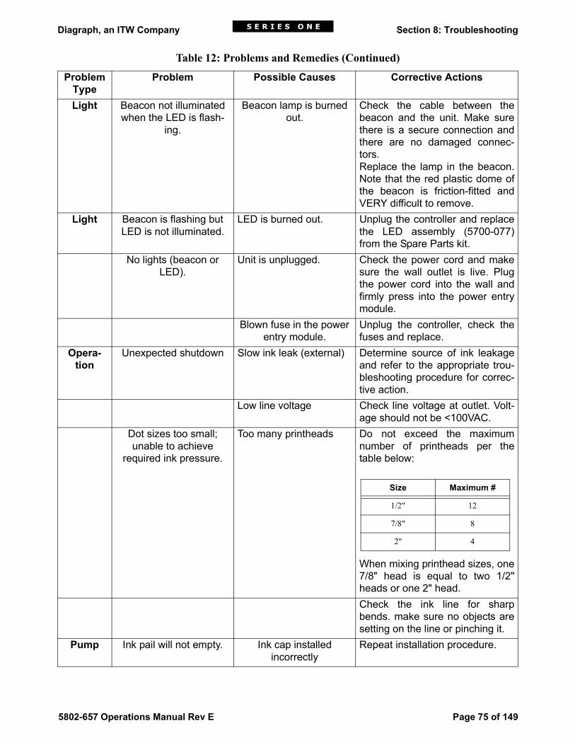
Diagraph, an ITW Company Section 8: Troubleshooting
5802-657 Operations Manual Rev E Page 75 of 149
Light Beacon not illuminated when the LED is flash-
ing.
Beacon lamp is burned out.
Check the cable between thebeacon and the unit. Make surethere is a secure connection andthere are no damaged connec-tors.Replace the lamp in the beacon.Note that the red plastic dome ofthe beacon is friction-fitted andVERY difficult to remove.
Light Beacon is flashing but LED is not illuminated.
LED is burned out. Unplug the controller and replacethe LED assembly (5700-077)from the Spare Parts kit.
No lights (beacon or LED).
Unit is unplugged. Check the power cord and makesure the wall outlet is live. Plugthe power cord into the wall andfirmly press into the power entrymodule.
Blown fuse in the power entry module.
Unplug the controller, check thefuses and replace.
Opera-tion
Unexpected shutdown Slow ink leak (external) Determine source of ink leakageand refer to the appropriate trou-bleshooting procedure for correc-tive action.
Low line voltage Check line voltage at outlet. Volt-age should not be <100VAC.
Dot sizes too small; unable to achieve
required ink pressure.
Too many printheads Do not exceed the maximumnumber of printheads per thetable below:
When mixing printhead sizes, one7/8" head is equal to two 1/2"heads or one 2" head.Check the ink line for sharpbends. make sure no objects aresetting on the line or pinching it.
Pump Ink pail will not empty. Ink cap installed incorrectly
Repeat installation procedure.
Table 12: Problems and Remedies (Continued)
Problem Type
Problem Possible Causes Corrective Actions
Size Maximum #
1/2" 12
7/8" 8
2" 4

Diagraph, an ITW Company Section 8: Troubleshooting
Page 76 of 149 5802-657 Operations Manual Rev E
8.9 Print Quality TroubleshootingHow to Use this Section:1. Look at the problem characters on your substrate and compare them with the figure
below to diagnose the exact name for the problem.2. Refer to Table 13, "Print Quality Definitions", to verify that you classified the problem
correctly.3. Refer to Table 14 to identify possible causes for your printing problem.4. See subsequent pages for solutions to various print quality problems.
Dot sizes too small, unable to achieve
required ink pressure.
Ink flow path obstructed Check the ink line for sharpbends. Make sure no objects aresetting on the line or pinching it.
Pump does not cycle on. Pump is defective. • Set ON/OFF switch to OFFand unplug unit from wall.
• Disconnect ink input from con-tainer at unit.
• Connect effluent bottle toprinthead line to depressurizeink supply; disconnect whenink stops flowing.
• Disconnect ink output to print-heads at unit.
• Loosen cover screws andremove controller cover.
• Follow the pump replacementinstructions later in this sec-tion.
Priming The prime button does not respond after holding it more than 30 seconds.
A time-out has probably occurred on the control-
ler.
Reset the prime button by switch-ing the mode switch from ON to OFF and back to ON. The prime button should again be active.
Possible punctured or disconnected ink line
Unplug the controller and discon-nect the ink out tube. Check
immediately for the ink leak loca-tion. Repair the break and recon-
nect power. Reset the prime button as above.
Flow path obstructed Check the ink line for sharp bends. Make sure no objects are setting on the line or pinching it.
Table 12: Problems and Remedies (Continued)
Problem Type
Problem Possible Causes Corrective Actions

Diagraph, an ITW Company Section 8: Troubleshooting
5802-657 Operations Manual Rev E Page 77 of 149
Table 13: Print Quality Definitions
Internal dot size variation The system prints dots that are different in size at the intersection of a dot column and a dot row.
Extra dots The system continues to print dots outside the designated dot columns.
Tails Dots with small trails of ink, usually a "tear drop" shape instead of a round dot.
Internal Dot Size Variation
Extra DotsTails
Splatter
Dragging Type Dot Size Variation
Undersized Dots
Stuck Open Valve
Oversized Dots
Off Target PrintingNo Print
Dot Columns out of Alignment
Smearing Print
Satellites

Diagraph, an ITW Company Section 8: Troubleshooting
Page 78 of 149 5802-657 Operations Manual Rev E
8.10 Print Problem CausesThe number one cause of poor print quality is distance to the substrate. The print-head must be within 1/8" of the product to be printed.The IV printhead works well when the pulse width, pressure and preload adjustments areall balanced properly. Too little or too much of any one will result in deteriorating print qual-ity and shortened printhead life.Troubleshooting the printhead must be conducted in this order:1. Check the distance to the product.2. Check the ink pressure.3. Check the pulse width.4. Check the preload.If ink pressure variation continues, perform the ink regulator maintenance procedure.
Splatter Dots with a fuzzy edge like the pattern created by the impact of a water balloon.
Dragging type dot size variation
The system prints smaller than average dot sizes at the beginning of print only.
Undersized dot Dots that are smaller than normal.
Stuck open valve The valve seal fails, allowing ink to stream from the ori-fice.
Oversized dot Dots that are larger than normal.
Off target printing One or more dots do not print in the expected location in the character.
No print, or missing dots The valve prints nothing.
Dot columns out of alignment
The dot columns line up in a zigzag pattern.
Smearing print The valve smears the dots together, forming a line.
Tails, splatter, off-target print
This combination of print quality defects means the print-head is too far away from the product.
Message broken A message that is broken into two or more pieces, usually from the encoder slipping.
Dynamic seepage* Ink leakage from orifices, only during printing.
Static seepage* Ink leakage from orifices, only when not printing.
*Seepage is defined as ink running down the front plate from one orifice far enough to connect to an adjacent orifice.
Table 13: Print Quality Definitions (Continued)

Diagraph, an ITW Company Section 8: Troubleshooting
5802-657 Operations Manual Rev E Page 79 of 149
Table 14: Print Problem Causes
Internal dot size variation • Low ink pressure (slight variation is normal)
Extra dots • High ink pressure• Pulse width set too high• Incorrect pre-load
Tails or satellites • Printhead too far from the target• Pulse width set too high• Incorrect pre-load
Splatter • Printheads too far from the target• Pulse width set too high• Orifice damaged by broaching
Undersized dot • Low ink pressure• Pulse width set too low• Incorrect pre-load
Stuck open valve • High ink pressure• Pulse width set too high• Incorrect pre-load
Oversized dot • High ink pressure
Off-target printing • Printhead too far from target• Low ink pressure
No print or missing dots • Low ink pressure• Pulse width set too low• Printhead failure• Controller or cabling failure• Solenoid failure• Clogged orifice• Membrane internal ink leakage due to broach punc-
ture
Dot columns out of alignment
• Encoder O-rings worn
Smearing print • Printhead too close to target• Make sure you are using the correct ink for your • application.
Message is broken • Photosensor is triggering multiple times per box.• Loose cable connections
Garbled printing • System improperly grounded• Excessive line noise
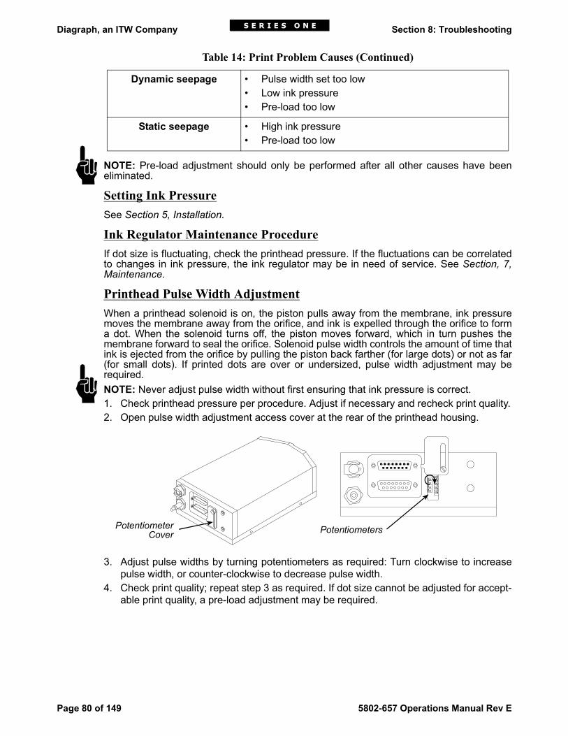
Diagraph, an ITW Company Section 8: Troubleshooting
Page 80 of 149 5802-657 Operations Manual Rev E
NOTE: Pre-load adjustment should only be performed after all other causes have beeneliminated.
Setting Ink PressureSee Section 5, Installation.
Ink Regulator Maintenance ProcedureIf dot size is fluctuating, check the printhead pressure. If the fluctuations can be correlatedto changes in ink pressure, the ink regulator may be in need of service. See Section, 7,Maintenance.
Printhead Pulse Width AdjustmentWhen a printhead solenoid is on, the piston pulls away from the membrane, ink pressuremoves the membrane away from the orifice, and ink is expelled through the orifice to forma dot. When the solenoid turns off, the piston moves forward, which in turn pushes themembrane forward to seal the orifice. Solenoid pulse width controls the amount of time thatink is ejected from the orifice by pulling the piston back farther (for large dots) or not as far(for small dots). If printed dots are over or undersized, pulse width adjustment may berequired. NOTE: Never adjust pulse width without first ensuring that ink pressure is correct.1. Check printhead pressure per procedure. Adjust if necessary and recheck print quality.2. Open pulse width adjustment access cover at the rear of the printhead housing.
3. Adjust pulse widths by turning potentiometers as required: Turn clockwise to increasepulse width, or counter-clockwise to decrease pulse width.
4. Check print quality; repeat step 3 as required. If dot size cannot be adjusted for accept-able print quality, a pre-load adjustment may be required.
Dynamic seepage • Pulse width set too low• Low ink pressure• Pre-load too low
Static seepage • High ink pressure• Pre-load too low
Table 14: Print Problem Causes (Continued)
2
4
6
8
1
3
5
7
9
PotentiometerCover Potentiometers

Diagraph, an ITW Company Section 8: Troubleshooting
5802-657 Operations Manual Rev E Page 81 of 149
Cleaning the Front Plate of a Clogged PrintheadIf dots are missing from the print, the printhead front plate may have dried ink or debris cov-ering the orifices. The front plate is made from graphite and can be damaged; do notattempt to scrape dried ink or debris from front plate. To clean the front plate:1. Wipe the front plate with a conditioner-wetted towel (towel should be very wet).2. A squeeze bottle of conditioner can be used to flush the front plate off.3. Purge the printhead; check if missing dots are purging.4. Wipe the front plate with a conditioner-wetted towel and inspect front plate. (There
should be no dried ink or debris on front plate).5. Repeat steps 1 through 3 until front plate is clean. If cleaning the front plate and purg-
ing do not clear the clogged orifice, follow the orifice broaching procedure.
Broaching the OrificeIf a printhead orifice is clogged or obstructed and wiping the front plate and purging will notclear it, the appropriate orifice should be broached.CAUTION: Failure to follow the broaching instructions can result in damage to the print-head.1. Wipe front plate with conditioner-wetted towel.2. Insert the broach into the orifice. Do not insert further than 1/10 inch.
CAUTION: Inserting the broach in the orifice deeper than 1/10 inch can puncture themembrane and cause a slow leak which will manifest itself as a no print failure severalweeks later, and void the printhead warranty.
3. Remove broach from orifice.4. Purge printhead.5. Repeat 3 or 4 times.6. If the clog or obstruction cannot be broached away, replace printhead.
Printhead Pre-Load AdjustmentPre-load adjustment is sometimes required, as printhead components wear over time.Pre-load adjustment may be required under the following conditions:• Excessive or constant ink leakage• Poor print quality in the form of tails, extra dots, splattering, or a stuck open valve.• Undersized dots (not correctable by pulse width adjustment) and purge die out (rarely)
are indications of over pre-loading.NOTE: If a valve is under pre-loaded, increasing the pre-load can correct the print problem.If the valve is over pre-loaded, the membrane or solenoid wire may be damaged to thepoint where the printhead will have to be replaced. Damage caused by too much pre-loadwill void the printhead warranty.The following is the proper procedure for adjusting I.V. printhead pre-load with the 1902-855 solenoid adjustment tool. This procedure is easiest to perform on a bench away fromthe line. When replacing a printhead, always install the new regulator supplied with theprinthead, and adjust pressure to the correct value.CAUTION: Failure to follow these instructions can result in damage to the printhead. Mak-ing adjustments with a tool other than the solenoid adjustment tool may damage the sole-noid bushings.
!
!
!

Diagraph, an ITW Company Section 8: Troubleshooting
Page 82 of 149 5802-657 Operations Manual Rev E
1. Make sure ink pressure is correct prior to making any adjustments.2. Remove printhead cover. A label inside
of the printhead cover indicates whichbushings and potentiometers to adjustfor each orifice.
3. Remove the rear frame plate by remov-ing the three mounting screws.CAUTION: Be careful to support theprinthead since it is only connected bythe solenoid wires to the driver boardafter the screws are removed. Allowingthe printhead to hang by the solenoidwires can damage the solenoids or driver board. Also, be careful not to allow the driverboard to come into contact with any metal items that might cause an electrical short.
4. Lift the rear frame plate/driver board assembly out of the way to provide access for pre-load adjustment. Handle the assembly by the rear frame plate.
5. Locate the row of bushings inside the printhead. The left side of the printhead coverlabel shows the layout of the bushings. The numbers inside the circles (bushings) cor-respond to the printhead orifices that they control.
6. Rotate the bushing counter-clockwise with the solenoid adjustment tool until inkstreams from the orifice. Ink will shoot out about three feet. Using a tool other than thesolenoid adjustment tool may damage the solenoid bushings.
7. Rotate the bushing clockwise until you see the ink stream deflect slightly.8. From this point, keep track of exactly how far the bushing is rotated (clockwise) to seal
the orifice.
PRINTHEAD COVER LABEL
2 4 3 1
8 6 5 9 7
13579
2468
5/16 5.07/8 6.0
PSI
SOLENOID LOCATION ORIFICE LOCATIONREAR VIEW OFSOL. MTG. BRKT.
SOLENOID ADJUSTMENT MUST BE MADE BY TRAINED PERSONNEL ONLY!
REAR VIEW OFFRONT MTG. BRKT.CAUTION!
BushingMountingScrews

Diagraph, an ITW Company Section 8: Troubleshooting
5802-657 Operations Manual Rev E Page 83 of 149
CAUTION: Do not rotate the bushing more than one full turn clockwise from this position,or the membrane or solenoid may be damaged, voiding the warranty.9. Rotate the bushing clockwise until ink seepage completely stops. 10. Wipe the front plate with a clean, conditioner-wetted cloth. Purge the printhead and
wipe again. Observe the printhead for 15 minutes; if ink seeps from the orifice, repeatsteps 8 through 10.
11. Rotate the bushing 1/8 of a turn, past the point where seepage stops. Do not exceedone full turn.
12. Install printhead in cover and check for seepage. If seepage occurs, remove printheadfrom cover and tighten bushing 1/8 turn. Do not exceed the one full turn limit.NOTE: If the one full turn limit is reached and the seepage has not stopped, replace theprinthead and return it to Diagraph for repair.
8.11 Replacing the PumpTools and Materials• Replacement pump kit (5700-966)• Effluent bottle• Disposable dry wipes• TFE tape or pipe joint compound• 3/8" socket wrench• Xacto knifeCAUTION: Always wear safety goggles when working with pressurized liquid systems.Open the controller pump replacement kit and identify all components. If there are missingor damaged parts, contact the Diagraph ServiceLine at 1-800-526-2531.
!
2
3
4
5
1
1 Tubing Connection to INK IN port2 Check valve for INK OUT port3 Molex connector to controller board4 24 volt AC pump5 1/8” tubing to manifold elbow

Diagraph, an ITW Company Section 8: Troubleshooting
Page 84 of 149 5802-657 Operations Manual Rev E
Removing the Faulty Pump1. Unplug the controller power cord.2. Connect the effluent bottle to the Ink Out port and wait for the accumulator to depres-
surize.3. Remove the controller cover.4. Disconnect the two-pin Molex connector to the pump.5. Remove the four nuts holding the pump to the base, and set them aside.6. Fold a dry wipe and place it under the 1/8" fitting on the input side of the pump.7. Using diagonal cutters, cut the 1/8" tubing connected to the input side of the pump.8. Press the wipe around the severed tubing to absorb any ink.9. Roll a fresh wipe and place it under the elbow fitting on the output side of the pump.10. Position the controller so that the electrical compartment is closest to you. This will
allow you to closely observe the next step and to gain leverage for cutting tubing.11. Using the Xacto knife, cut the tubing between the elbow fitting on the output side of the
pump and the elbow fitting on the accumulator.12. Press the wipe around the cut to absorb leaking ink.13. Remove the pump from the housing and clean up any ink drips.14. Use the diagonal cutters to carefully nibble away the tubing that remains on the mani-
fold elbow fitting. Take care not to cut or scar the fitting. Clean with a wipe when com-plete.
15. Using the diagonal cutters, carefully pinch and pull the 1/8" tubing from the fitting on theINK IN port. Take care not to cut or scar the fitting. Clean with wipe when complete.
Installing the New Pump1. Place the new pump in position.2. Use TFE tape or pipe joint compound on the threads of the elbow on the accumulator
and slide on the tubing from the output side of the pump.3. Use the tape or joint compound on the threads of the male fitting on the purge switch
and slide on the tubing from the input side of the pump.4. Connect the two pin Molex connector to the pump.5. Secure the pump to the housing with the nuts set aside when the old pump was
removed.6. Reconnect ink lines and the effluent bottle.7. Turn on system power.8. Press the prime button; you should hear the pump start. If it does not, unplug the power
cord and check the Molex connector to the pump.9. Hold the prime button until the air evacuates the line and ink runs into the effluent bot-
tle.10. Release the prime button and disconnect the effluent bottle.11. Press the prime button until the system comes up to pressure.12. Replace the system cover.

Diagraph, an ITW Company Appendix A: System Specifications
5802-657 Operations Manual Rev E Page 85 of 149
Appendix A: System Specifications
DescriptionThe Series 1 Controller incorporates the Telemark logic board with a modified (connectoronly) encoder and photosensor. It controls I.V. printheads and houses an ink delivery sys-tem (IDS).The following features provide increased capability and versatility:• Interface board that converts parallel data to serial data• Split line configuration: Dual encoder and photosensor inputs• Daisy chain up to two 9-dot printheads• Internal fixed speed reporter or variable speed reporter• Hand-held terminal interface• External interface
•Low ink alarm•Message advance
• Stainless steel enclosure (EMI, RFI)• Reduced cabling (internal and external)• Improved appearance (internal and external)• Integrated electronics and ink system• Easily upgradeable 1-4 head controller; for customers who want to go beyond four
printheads, the data line can be connected to additional Series 1 controllers.
Controller/IDSTable 15: Controller/IDS Specifications
STAND-ALONE PC-BASED
Input Device LC/400 Hand Held Terminal IBM Compatible PC
Communication RS-232 to TerminalRS-422 Controller to Controller
RS-232 or RS-422 to PCRS-422 Controller to Con-troller
External Sources N/A Scale, Scanner or otherRS-232 interface device
Autocodes Standard: Date, time, Julian/Gregorian date, sequentialnumbering, pallet count.Special Software: Completelibrary of custom and specialautocodes available.
Standard
Special
Message Storage 99 40-character messages Number of 149-charactermessages limited only byPC storage space
Printheads per Input Device
Up to 15; 4 per controller, 15networked
Up to 16; 4 per controller,16 networked

Diagraph, an ITW Company Appendix A: System Specifications
Page 86 of 149 5802-657 Operations Manual Rev E
Font Capabilities 9-dot single and bold, 7-dotproportional and fixed width.18-dot upper and lowercase,special fonts or logos availableupon request.
Full ASCII character set,single, bold, extra bold,condensed, expanded,inverted, reversed, 18-, 9-,7- and 5-dot tall matrices,multiple sizes and fonts onthe same line.
IDS Efficiency 99.9%; less than 1 oz. remains in the pail after use.
Dimensions (Overall) 19.125" x 8.25" x 17.75" (486mm x 210mm x 451mm)
Weight 35.4 lb. (16.6kg)
Case Material Industrial grade stainless steel with fully gasketed plasticfront cover.
Electrical 115/230VAC; 50/60Hz: 5700-969100/200VAC; 50/60Hz: 5700-801
Temperature Operating: 40°F to 100°F (4.4°C to 37.8°C)
Fluid Connections 1/8" female quick disconnect for ink inlet1/4" female quick disconnect for ink outlet
Manual Controls(Front Panel)
ON/OFF SWITCHVOLTAGE/FUSE SELECTOR: Voltage SelectionPUMP PRIME BUTTON: Override auto shutoff
Enclosure Industrial grade stainless steel
Ink Accumulator Capacity
1.4 oz. (40ml) ink available for printing
Fuses System: 2 MDL-2 250V, 2AFan: 1 125V, 315mA
Table 15: Controller/IDS Specifications (Continued)
STAND-ALONE PC-BASED

Diagraph, an ITW Company Appendix A: System Specifications
5802-657 Operations Manual Rev E Page 87 of 149
Table 16: Printhead Supply Capacities
IV Printhead Size Maximum # Printheads
1/2" 12
7/8" 8
2" 4
Barcode 4
0
2
4
6
8
10
12
14
16
18
0 5 10 15 20 24
Height in Feet
ON
/Off
Pres
sure
(PSI
G)
Pump On PressurePump Off PressureMinimum Pressure

Diagraph, an ITW Company Appendix A: System Specifications
Page 88 of 149 5802-657 Operations Manual Rev E
PhotosensorSeries 1 applications use the Allen-Bradley 42SRP-6002, diffuse type photosensor. Thistype of photosensor detects LED radiation scattered back from a diffuse reflective surface.It is designed for use in applications where reflectors or emitters cannot be mounted.
Table 17: Photosensor Specifications
Voltage Supply 10-30VDC
Supply Current 30mA
Output Energized Light
Output Type NPN and PNP
Output Rating 200mA
Response Time 1ms
Operating Distance with White Paper 2:1 Margin: 32" (81cm)
Reverse Polarity Protection Yes
Transmitting LED Infrared 880nm
Field of View 7.5
Ambient Temperature -40°F to 150°F

Diagraph, an ITW Company Appendix B: Theory of Operation
5802-657 Operations Manual Rev E Page 89 of 149
Appendix B: Theory of OperationThe Series 1 controller prints text onto products as they pass through a print station via aconveyor. The conveyor speed is monitored using a variable speed encoder and productsare detected using a photosensor. The text to be printed is defined as a message and issent to the controller from a PC or hand-held terminal.
Controller/IDS FeaturesThe following components are contained within the Series 1 controller/IDS:
Interface Board (5700-567)The Logic boards supply parallel print data tothe Interface board print data set-up and datashift circuits. If either logic board has data toprint, the print set-up circuit generatesRCLOCK, which loads the parallel print datafrom both Logic boards into the shift circuit,and generates a TRIGGER signal that ini-tiates the print cycle. The timing circuit pro-vides CLOCKOUT to the shift and dataconversion circuits; it also generates theLATCHOUT pulse to fire the printhead sole-noids after 18 CLOCKOUT pulses. The datashift circuit converts the parallel print data intoserial data SROUT. CLOCKOUT, LATCHOUTand SROUT are supplied to the differentialconverter to supply the proper printhead dataformat at the printhead connector.Printhead power (15VDC) is also output onthe printhead connector. The encoder input isfed to the logic boards and an 18 dot sync cir-cuit; a jumper selectable internal line speedoscillator is located on the board for fixedspeed applications. The photocell operateson 15VDC and the input signal is opto-iso-lated. The encoder, photocell and low ink sig-nals are available on the inter-boardconnector (P21). Terminal data can be RS-232 or RS-422(jumper selectable). RS-422 is fed straightthrough to the logic boards, while RS-232data is converted to RS-422 for use by the logic boards. The reset circuit provides a one-second pulse (/RES) to clear all counters and registers at power-up. "Message Advance"and "Purge" push buttons are also located on the interface board.
Logic Board (5701-061)The Logic boards operate independently, and each controls one 9-dot printhead. The Logic boards receive RS-422 data from the terminal through the Interface board.When the photosensor is active, the Logic board counts the encoder ticks for the delay, andbegins to send the parallel print data to the Interface board. The message is assembledone character at a time from the selected font, and sent one column at a time in two sec-tions (odd and even columns) to the interface board. (Note that because of the dual columnprinthead, the odd and even column data can not be sent simultaneously.) The Logic board address and some options are set by the DIP switches located on theLogic board; LEDs provide board status information.
P9 J1
J3 J4
J5 J2
J10 J11
ENCODERPRINTHEADS
15 VOLTSUPPLY
5 VOLTSUPPLY
LOW INKSIGNAL PHOTOSENSOR
DATA DATA

Diagraph, an ITW Company Appendix B: Theory of Operation
Page 90 of 149 5802-657 Operations Manual Rev E
Ink Delivery SystemA microprocessor based IDS controller board assembly (5700-749V11) controls the pro-cess of pumping ink via a 24VAC pump. Ink is pumped from an external container into aspring-loaded accumulator, which pressurizes the output of the IDS. The microprocessordetermines the relative position of the accumulator rod to establish the operating pressurerange. The microprocessor uses the three accumulator rod sensor points, detected by theinfrared emitters and detectors located on the sensor board (5700-750), to establish the inkout, pump ON and pump OFF pressure points as follows:1) The system is out of ink if the accumulator rod does not break the infrared beam of theink out (minimum) position. The microprocessor will illuminate the ink out beacon and waitfor the system to be manually primed. The accumulator rod will pass through the minimumpressure point once the system has been successfully primed. The microprocessor willthen ignore the manual prime switch, begin automatic control and activate the pump. Afirmware time-out exists during the manual priming process. An error will be generated(power ON LED will begin flashing) if the accumulator rod does not reach the ink out (mini-mum) position. (See Section 7, Troubleshooting.)2) The pump will remain ON until the accumulator rod passes through the infrared beam ofthe pump OFF (maximum) position, whereupon the microprocessor will turn the pump OFF.3) The accumulator pressure will slowly decrease while the system is printing. The pumpwill remain OFF until the accumulator rod passes through the infrared beam of the pumpON (medium) position. The microprocessor will then activate the pump, increasing pres-sure. The pump will remain ON until the accumulator rod passes through the infrared beamof the pump OFF (maximum) position, whereupon the microprocessor will turn the pumpOFF. A firmware time-out exists during the pump ON cycle. The pump will be turned OFF and anerror will be generated (power ON LED begins flashing) if it takes more than 45 seconds forthe accumulator rod to move from the medium (pump ON) to the maximum (pump OFF)position. (See Section 7, Troubleshooting.)The beacon will illuminate when accumulator pressure falls below the ink out position. Theresistance of the beacon is monitored by the microprocessor and an error is generated ifthe bulb is burned out or if the beacon is not connected. (See Section 7, Troubleshooting.)
Power SuppliesA quad output switching power supply (5700-091) is mounted on the top of the controllerassembly. Only two output voltages are used, 5VDC and 15VDC. 5VDC is supplied to theinterface board, logic board and encoder. 15VDC is supplied to the printheads and the pho-tosensor.The Ink Delivery System is powered by a 24VAC step down transformer (5700-963)located on top of the controller assembly. 24VAC is supplied to the IDS controller board,pump and the beacon.
PrintheadsThe only source of power for the printheads is the 15VDC received from the interfaceboard. The 15VDC is protected by a 4A fuse soldered onto the driver board. This fuse isnot considered a replaceable part. The 15VDC is daisy chained to the second printhead.Thus, the second printhead will not have power if the fuse is blown on the first printhead,though the first printhead may still have power if the fuse in the second printhead is blown. The interface board transmits 18 dots of differential serial data to the first driver board(located inside the rear of the housing). The CLOCK signal shifts the first 9 dots throughthe first driver board to the second printhead while the second 9 dots are shifted into thefirst printhead. The LATCH signal is provided to both printheads. Once the CLOCK signalhas shifted all 18 dots of print data into the printheads, the LATCH signal is generated toactivate the selected printhead solenoids, and a message is printed. The printhead driver board receives clock, data and latch signals from the interface boardand converts them to separate 15-volt pulses of between 250 and 450 milliseconds in

Diagraph, an ITW Company Appendix B: Theory of Operation
5802-657 Operations Manual Rev E Page 91 of 149
length for each solenoid. When the solenoid receives the pulse, the coil magnetizes, pull-ing the drive wire connected to the piston back about 0.003". Ink pressure forces the mem-brane off the seal, allowing ink to escape through the orifice. The entire process takesabout one millisecond. Adjustment of the dot size is accomplished via the potentiometerson the back of the driver board, sometimes called the "pulse width" adjustment.Inside each solenoid is a leaf spring that holds the piston against the membrane with about0.06 pounds of force. This sealing force is called preload. While the preload may some-times require adjustment after long use, too much preload will damage the membrane sealor even bend the solenoid drive wire, either of which will make the printhead inoperableand void the printhead warranty.
Ink pressure set at the printhead’s recommended PSIG provides the necessary force forthe ink drops to escape the orifice and travel the distance to the box. The distance to thebox should be about 1/8". Print quality is inversely proportional to the distance to the box.IV printheads work well when the pulse width, pressure and preload adjustments are allbalanced properly. Too much or too little of any one will result in deteriorating print qualityand shortened printhead life.
Fluid Entry Line
Pistons
FrontPlate
Membrane
Ink ManifoldReservoir
Ink Drop
Orifice
BackPlate
SolenoidDrive Wire

Diagraph, an ITW Company Appendix B: Theory of Operation
Page 92 of 149 5802-657 Operations Manual Rev E
Ink RegulatorThe ink regulator (supplied with the printhead) regulates the ink pressure to the printhead.The ink regulator is directional, and so should always be connected to the top printhead fit-ting, the female quick disconnect.The ink regulator operates by balancing a valve sealing an orifice and reinforced EPDMdiaphragm between a stainless steel spring in the bottom, and a non-wetted spring in con-tact with the adjustment knob on top.When ink pressure into the middle chamber of the regulator exceeds the ink pressure inthe outer chamber, ink flows through the orifice. The diaphragm stretches as pressurizedink fills the outer chamber, until the stem mounted to the middle of it lifts off the valve, allow-ing the bottom spring to seal it up against the orifice.The output pressure is produced by the stretched diaphragm. As ink is used by the print-head, the diaphragm relaxes, the stem pushes the valve seat away from the orifice seal,and ink flows back into the outer chamber until pressure is restored by the tension on thediaphragm. The stroke length of the valve is a function of how far down the valve stem is allowed topush it during recharging. That stroke length is controlled by setting the knob. Clockwiserotation of the knob compresses the top spring, increasing the stroke length and thus theink pressure output. When fully counterclockwise, the diaphragm stem is no longer in con-tact with the valve seat and no ink will flow through the ink regulator once the ink remainingin the outer chamber (normally about 2 ml) is exhausted.The ink pressure gauge (5700-743) is used to indicate ink pressure, and must be usedwhen making pressure adjustments to the system to maintain print quality.

Diagraph, an ITW Company Appendix C: Testing an Electrical Outlet
5802-657 Operations Manual Rev E Page 93 of 149
Appendix C: Testing an Electrical OutletAn outlet tester is the preferred method of checking an electrical outlet, although a voltme-ter can also be used.
Background Information About AC WiringEquipment running at 115VAC must have one hot wire and one neutral wire. Additionally, aseparate ground wire runs to non-current carrying parts of most loads.
*The service equipment is defined as “the equipment used to disconnect the entire buildingand over-current device to protect the entire installation, but not the branch circuits individ-ually.”At the service equipment, a single ground wire connects both the neutral and ground toearth. The NEC calls this wire the “ground electrode conductor.”
Table 18: The Wires in an AC Outlet (115VAC)
WIRE DESCRIPTION FUNCTIONLINE Usually black. Cannot be white or
green.Carries the voltage load to the equip-
ment.NEUTRAL White or natural gray. Grounded at the service equipment*
only. Serves as the return for 115 volts.GROUND Bare, green or green with yellow
stripes; may be metal armor or metal conduit.
Grounded at the service equipment* and every metal box or cabinet. Runs to non-current, carrying parts of most
loads.
115VAC
HOTNEU
GND
0V 115VAC
115VAC
115VAC 0V
0V
115VAC 115VAC
CORRECTLY WIREDOUTLET
INCORRECTLY WIREDHOT AND NEUTRAL
REVERSED
INCORRECTLY WIREDHOT AND GROUND
REVERSED

Diagraph, an ITW Company Appendix C: Testing an Electrical Outlet
Page 94 of 149 5802-657 Operations Manual Rev E

Diagraph, an ITW Company Appendix D: Electrostatic Discharge
5802-657 Operations Manual Rev E Page 95 of 149
Appendix D: Electrostatic DischargeWhat is ESD?Electrostatic Discharge (ESD) is a triboelectric charge generated by separating or rubbingtogether two non-conductive materials.
What causes ESD?Friction can cause ESD. Friction can be generated by walking across a floor, removingtape from a tape dispenser, pulling a work order from a plastic sleeve, rolling the wheels ofa push-cart across the floor, sitting on a foam cushion such as a stool or blowing air acrossa nonconductive surface.
ESD at the print station can be caused by the product rubbing against ungrounded guiderails, conveyor belt static voltage build-up, or a residual static charge on the product fromearlier processing.Generally, ESD problems are more prevalent in the winter months. Heated air has a muchlower relative humidity than the cold air had prior to heating. In many instances ESD prob-lems appear in the fall when the outside temperature drops, and go away in the springwhen the outside temperature begins to rise.
What Are the Effects of ESD?Unexplainable system resets, controller lockups, and multiple prints on the product can besigns of static discharge to the system. When static electricity is discharged to an electroniccircuit (components or printed circuit boards), permanent damage may also occur. Thisdamage may be in the form of reduced functionality, reduced life, or complete non-function-ality. The static charge does not have to be noticeable to the human touch in order to causeproblems in an electronic system. A human being does not start to feel the effects of staticelectricity until the voltage reaches or exceeds 4000 volts. Voltage as small as 100 voltscan cause problems with some sensitive electronic components.
What Prevents ESD?Prevention begins with training and knowledge. The use of wrist straps, heel straps, work-bench mats, floor mats, and monitoring systems for electronic devices will drasticallyreduce the ill effects of ESD when handling circuit boards. Anytime you handle electroniccomponents or printed circuit boards, ESD wrist straps should be used.If static discharge is suspected of causing controller problems at the print station, check thegrounding of the conveyor and print station components. Nonconductive or ungroundedguide rails are the most common cause of static discharge. Ionized air blowers and staticdissipating material have proven effective in eliminating many static problems.
Table 19: Causes of Electrostatic Discharge
Source 70-90% RelativeHumidity Volts
10-20% RelativeHumidity Volts
Walking across a carpet 1,500 35,000
Working at a bench 100 12,000
Sitting on a foam cushion 600 20,000
Removing plastic bag from bench 12,000 20,000
Removing work order from plastic sleeve 600 7,000

Diagraph, an ITW Company Appendix D: Electrostatic Discharge
Page 96 of 149 5802-657 Operations Manual Rev E

Diagraph, an ITW Company Appendix E: IDS Performance
5802-657 Operations Manual Rev E Page 97 of 149
Appendix E: IDS PerformanceThe information in this section will be useful in new system installations and for trouble-shooting installed systems that have suspected pressure problems. What follows is a controlled measurement of Series-1 ink delivery system performance.TWP conditioner pressure versus flow at various vertical and horizontal distances wasmeasured. The results may be used for all TWP ink types. The ink delivery system must switch on between 12.5 and 14.0 PSIG, and off between 16.5and 19 PSIG, while having a minimum on/off differential of 4.0 PSIG. Switching on and offwithin these pressure limits and running at a 50% or less pump duty cycle provides for ade-quate ink flow to support the maximum number of printheads (four 9-dot printheads) whileminimizing pump wear.
Vertical Height MeasurementsFor the following measurements, the system was set up with a 20% pump duty cycle, pro-ducing about a 100 milliliter per minute flow rate. The pressure at which the ink pumpswitched on and off was measured at the fluid output of the indicated height in feet.
There must be a minimum of 2PSIG difference between the lowest ink pressure from theSeries-1 controller and the ink regulator output, to guarantee adequate pressure control tothe printhead. Therefore, finding the required printhead pressure on the chart above, andadding 2 PSI to it, determines the maximum height (in feet) above the ink container that theprintheads may be located. For example, a 6.0 PSIG printhead cannot exceed 13.5 feet inheight above the container.The pressure drop of any upward run of ink is canceled by a downward drop of equallength. For example, an upward run of 24 feet of ink line matched by a downward run of 24feet of ink line, has an on and off pressure equal to that of zero feet. If the line goes up 24feet and down 19 feet, then the pressure will be equal to a 5-foot height differential. Also,be careful to fill the tube with fluid, evacuating all of the air, prior to running the tubebetween the ink supply and the printheads. If air is left in the line, it will decrease the flowrate, though it will not affect the pressure.
0.01.02.03.04.05.06.07.08.09.0
10.011.012.013.014.015.016.017.0
0 1 2 3 4 5 6 7 8 9 10 11 12 13 14 15 16 17 18 19 20 21 22 23 24Height (Feet)
Pump On PressurePump Off PressureMinimum ²P

Diagraph, an ITW Company Appendix E: IDS Performance
Page 98 of 149 5802-657 Operations Manual Rev E
Horizontal Distance MeasurementsFor the following measurements, the system was set up at 20, 40 and 60% pump dutycycles, producing flow rates of 100, 190 and 270 milliliters per minute, respectively. Thepressure at which the pump turned on and off was measured at the fluid output of the indi-cated distance in feet from the controller (at a height of 3 feet above the ink container).
As indicated on the chart above, the pressure loss over a substantial horizontal length oftubing is considerably less than that of even a short vertical length. Once again, a 2.0 PSIGpressure differential is required between the ink regulator input and output. As indicated bythe graph, the Series-1 ink delivery system can support ink line lengths of up to 300 feet.NOTE: Always be extremely careful to follow any local codes covering the installation ofpressurized liquid lines. Additionally, avoid potential entanglement in other equipment.
10.0
11.0
12.0
13.0
14.0
15.0
16.0
17.0
18.00 25 50 75 100
125
150
175
200
225
250
275
300
Horizontal Distance (Feet)
20% @ 100; On20% @ 100; Off40% @ 190; On40% @ 190; Off60% @ 270; On60% @ 270; Off
Duty Cycle @ Flow Rate (mls/min); Pump

Diagraph, an ITW Company Appendix F: Maximum dpi Calculation
5802-657 Operations Manual Rev E Page 99 of 149
Appendix F: Maximum dpi CalculationThe maximum line speed of an I.V. printhead is limited by the maximum frequency of thesolenoid, which is 1000 Hz. The following steps will determine the operating frequency ofthe solenoids in the application. The attached graph can also be used to determine themaximum print resolution for a given line speed.1. Determine the values for:• Line speed in feet per minute: If a tachometer is not available, the line speed can be
estimated by measuring the conveyor belt and using a stop watch to time one completerevolution of the belt. For example, a 20-foot, 7-inch conveyor belt takes 34 seconds tomake a complete revolution. Divide 60 seconds by the number of seconds per revolu-tion (34 in this case). Multiply the resulting number by the length of the belt (21 feet inthis example; always round up to the next foot for this calculation). The answer is 37feet per minute (60/34 x 21 = 37).
• Character Width in inches: In the Series 1, character width is selected through the soft-ware. This setting is measured in 0.01-inch increments; a setting of 4 means that thedistance between the center of one dot column and the center of the next dot column is0.04 inches. The character width must be set between 2 and 25.
2. The operating frequency of the solenoids can be determined with these two parametersby following the next two steps:
• Determine the line speed in inches per second. Divide the line speed in feet per minuteby 5 to get inches per second. A line speed of 200 feet per minute is equal to 40 inchesper second (200/5 = 40).
• Multiply the number of inches per second by the dpi setting to determine the solenoidoperating frequency in Hz (cycles per second). Printing at 25 dpi, at a line speed of 40inches per second, would result in a frequency of 1000 Hz (40 x 25 = 1000).
The operating frequency of an I.V. printhead must be less than or equal to 1000 Hz. If itexceeds 1000 Hz, the printhead will have reliability and print quality problems. In such acase, the best solution is to decrease the print resolution, which will decrease the operatingfrequency.To determine the maximum print resolution for a given conveyor, divide 1000 by the con-veyor speed in inches per second. Using the previous example, 1000 divided by 40 inchesper second equals 25 dpi maximum print resolution. Even if a higher resolution is desired,the I.V. print head is not capable of it without encountering performance and reliability prob-lems.

Diagraph, an ITW Company Appendix F: Maximum dpi Calculation
Page 100 of 149 5802-657 Operations Manual Rev E

Diagraph, an ITW Company Appendix G: Host Interface Guide
5802-657 Operations Manual Rev E Page 101 of 149
Appendix G: Host Interface GuideThis appendix applies only to PC-based systems.
Defining the InterfaceThe Series 1 controller communicates to a PC or other host device through either RS-232or RS-422 serial communications. There are three interface options shown below:
Option 1: PC (9-pin RS-232) to Controller
PC Controller
5700-721 10 ft. cable (Optional: 5700-939 100 ft cable)
PC Controller
5700-722 10 ft. cable (Optional: 5700-939 100 ft cable)
ControllerController
5700-587 10 ft. cable (Optional: 5700-945 100 ft. cable)
Option 2: PC (25-pin RS-232) to Controller
Option 3: Controller to Controller

Diagraph, an ITW Company Appendix G: Host Interface Guide
Page 102 of 149 5802-657 Operations Manual Rev E
The ConnectionThe Series 1 Controller houses an interfaceboard and one or two logic boards. The inter-face board enables the logic board(s) to com-municate with the host through physicalconnections and if necessary, by serial stan-dard conversion. When the interface boardreceives an RS-232 connection, it convertsthe RS-232 signal to RS-422 for communica-tion with the logic boards.The interface board has two data ports thatprovide the same functionality at either con-nection. These ports enable loop communi-cations for up to 16 logic boards in multi-dropconfigurations by cross-connecting interfaceboards.
Connection FunctionalityThe serial ports operate with four signals anda ground:• Data In (RX)• Data Out (TX)• Request to Send (RTS)• Clear to Send (CTS)RX and CTS are input signals to the logicboard while TX and RTS are outputs from thelogic board.
The host sends the CTS (high) when it is ready to receive data from the logic boards. TheCTS is normally high, since input is minimal and buffer storage is not usually a problem.The logic boards send the RTS when they are ready to receive data from the host. TheRTS is very important for proper communication with the logic boards; using the RTS toenable and disable the host transmitter is highly recommended. In a multi-drop configuration, the transmitters for each logic board are disabled and there-fore, effectively disconnected from the circuit. Sending data to the host from the logic boardenables the logic board transmitter.
Table 20: J10 and J11 Pinouts
Pin #
Function Pin #
Function Pin #
Function
1 Ground 6 232RX 11 TXD-
2 RXD+ 7 232TX 12 RTS-
3 TXD+ 8 232CTS 13 CTS-
4 RTS+ 9 +VCC (+5VDC) 14 232DTR
5 CTS+ 10 RXD- 15 +VDD (+15VDC)
P9 J1
J3 J4
J5 J2
J10 J11
ENCODERPRINTHEADS
15 VOLTSUPPLY
5 VOLTSUPPLY
LOW INKSIGNAL PHOTOSENSOR
DATA DATA

Diagraph, an ITW Company Appendix G: Host Interface Guide
5802-657 Operations Manual Rev E Page 103 of 149
ProtocolThe default setting is 9600 baud, 8 data bits, 1 stop bit, even parity; set by DIP switch 4 andthe baud rate jumpers on the logic board.
DIP switch 4 also determines the need for a cyclical redundancychecksum (CRC). An OFF setting indicates the signal is evenparity without a CRC. If it is ON, the signal has no parity and atwo-byte CRC must follow each message.
CRC Calculation ProgramThe following code is written in C:/*CRCO
Factor a new character into the running CRC value .2From 'EDN' magazine 6/4/79 page 84.Based on the CCITT standard polynomial:X ˆ 16 + X ˆ 15 + X ˆ 13 + X ˆ 7 + X ˆ 4 + X ˆ 2 + X + 1
The algorithm is:1. Shift CRC word left one bit (i.e., double it), saving carry in Q-bit.2. Add new character to low byte of CRC only, ignoring carry.3. If Q-bit not zero, then EXCLUSIVE OR the CRC word with hex A097. The Q-bit repre-
sents Xö16, the hex value A097 is the rest of the above polynomial.
The CRC word is kept as two bytes and should be initialized to 0, before the first call to thisroutine.*/char crclow, crchigh:
crc0 (newchar)
Table 21: Baud Rate Settings
Baud RateJumpers
DIP Switch 4 ONCRC ON
DIP Switch 4 OFF
CRC OFF
C 9600 38400
D 4800 19200
E* 2400 9600
F 1200 4800
G 600 2400
H 300 1200
*Default Setting
HHHH GGGG FFFF EEEE DDDD CCCCOOOO OOOO OOOO OOOO OOOO OOOOOOOO OOOO OOOO OOOO OOOO OOOO
DEFAULT SETTING

Diagraph, an ITW Company Appendix G: Host Interface Guide
Page 104 of 149 5802-657 Operations Manual Rev E
char newchar;{
char qbit:,
/* Set Q bit true if left shift will produce carry out of high CRC byte */qbit = crchigh > 127;
/* Shift CRC word left one bit (i.e. double it) */crchigh += crchigh; /* Add high CRC byte to itself */if (crclow > 127) crchigh += 1; /* Add carry from low CRC byte */crclow += crclow; /* Add low CRC byte to itself 8?
/* Add new character to low byte of CRC only, ignoring carry. */ crclow += newchar;
/* If Q-bit not zero, then EXCLUSIVE OR the CRC word with hex A097. */If (qbit) {
crchigh ˆ= 0xA0;crclow ˆ= 0x97;
}}
SyntaxLogic boards only respond to requests from the host-they transmit nothing without arequest. All communication between the host and the logic board(s) share the formatshown in the table below:
STX: Start text character, hex Ø2Logic Board # Address number of the logic board. DIP switches 5 through 8 set the binaryaddress (0-Ah) of each logic board (see Section 5, Installation, for address number combi-nations). FFh is a global address and will transmit a message to all logic boards in a multi-board system. All logic boards will react to the message but not return a response.Byte Count: Length, in bytes, of the message portion of the transmission that beginsimmediately after the byte count byte. The CRC, if implemented, is not included. NOTE: If the message (command plus parameters) is greater than the byte count value,the logic board will ignore the additional bytes after the specified byte count. If the messageis smaller than the byte count value, the logic board will hang while waiting for more char-acters until a time-out occurs. In either case, if a CRC is part of the transmission, the entiremessage will be ignored since the CRC will not match the count.Command Byte: Actual desired action.Message/Data: Requisite data for the designated command.
Pseudo-code
STXØxØ2h
Logic Board #
Byte Count Command Byte
Message/Data
Optional CRC
Bytes 1 1 1 1 Variable 2

Diagraph, an ITW Company Appendix G: Host Interface Guide
5802-657 Operations Manual Rev E Page 105 of 149
Information ExchangeThe basic exchange of information consists of the host requesting or sending informationfollowed by the logic board's response. There are four possible logic board responses:1. ACK acknowledge, (06h)2. NAK negative acknowledge, (06h)3. S status, (53h) followed by ten bytes of status information4. P parameter, (50h) followed by four bytes of configuration informationEvery message from the host must receive a positive acknowledgment from the logicboard. The sole exception is the FFh global address to all logic boards. In the case of astatus request or parameter request, sending the status or parameter message acknowl-edges receipt of the request. For all other messages, the logic board sends an acknowl-edge (ACK 06h) message, if it received the message from the host. If the logic board doesnot respond within 50 milliseconds, the host should re-transmit. If repeated transmissionsfail, the host should use Reset to reset the logic board. The ACK indicates the logic boardreceived the request and will process the request.NOTE: Once the host begins transmitting to a logic board, it must transmit each byte within200 milliseconds of the previous byte or the logic board will have a time-out, assume thatpart of the message is missing, and discard the entire message.Message ExampleSend the message "ABC" to logic board one (address Øh) to print on every box. Thedefault is 9600, 8, 1, e (no CRC).
Response from the logic board:
Printing from Keyboard via DOSThe following procedure sends a command to the controller, address 2, to print ABC.From the DOS prompt type:
MODE COM1 : 96, E, 8, 1 <ENTER> (substitute proper COM port if COM1 is not correct)COPY CON COM1 <ENTER>
Complete the following keystrokes:Press CTRL+BRelease the CTRL+keyPress CTRL+ARelease the CTRL+keyPress CTRL+D
Pseudo-code
STX(ØxØ2h
LogicBoard #
Byte Count
Command byte and parameters
Optional CRC
Hex 02 00 04 45 41 42 43 N/A
Decimal 2 0 4 69 65 66 67 N/A
Pseudo-code
STX(ØxØ2h
LogicBoard #
Byte Count
Command byte and parameters
Optional CRC
Hex 02 00 01 06 N/A
Decimal 2 0 1 6 N/A
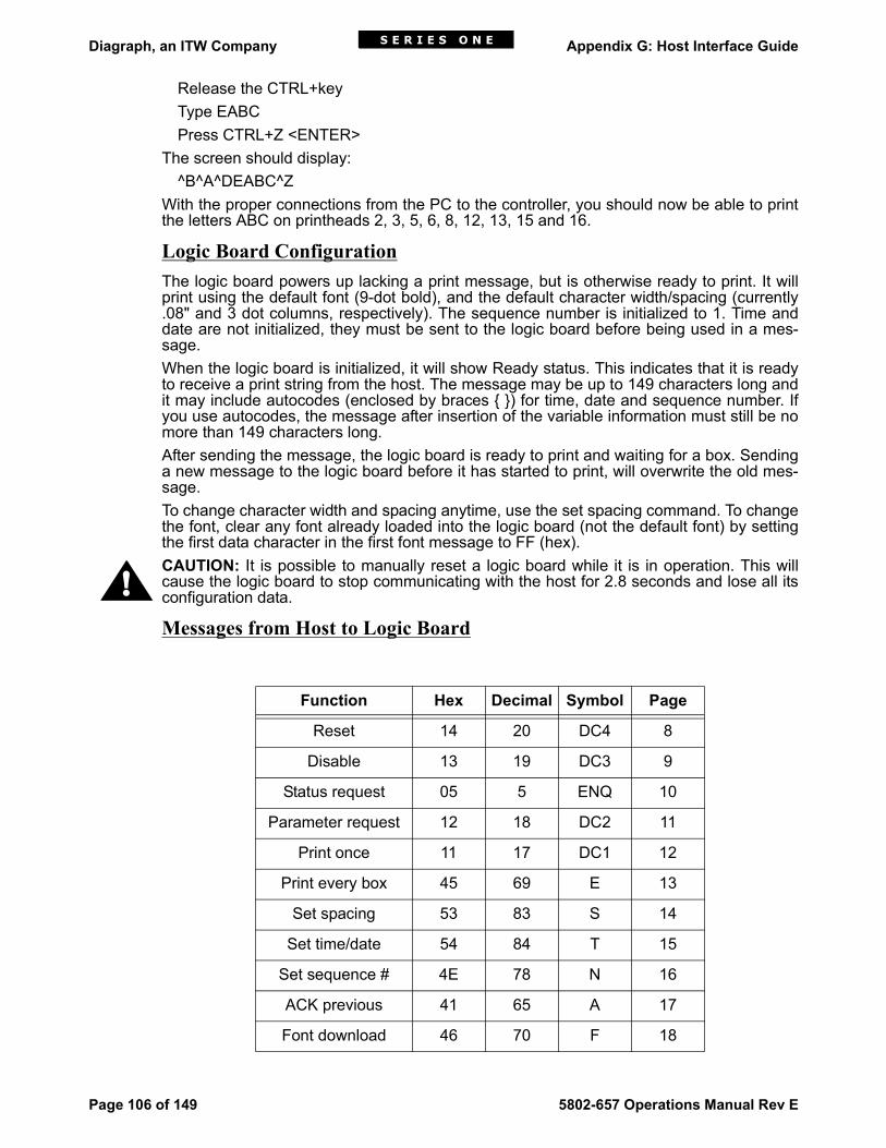
Diagraph, an ITW Company Appendix G: Host Interface Guide
Page 106 of 149 5802-657 Operations Manual Rev E
Release the CTRL+keyType EABCPress CTRL+Z <ENTER>
The screen should display:^B^A^DEABC^Z
With the proper connections from the PC to the controller, you should now be able to printthe letters ABC on printheads 2, 3, 5, 6, 8, 12, 13, 15 and 16.
Logic Board ConfigurationThe logic board powers up lacking a print message, but is otherwise ready to print. It willprint using the default font (9-dot bold), and the default character width/spacing (currently.08" and 3 dot columns, respectively). The sequence number is initialized to 1. Time anddate are not initialized, they must be sent to the logic board before being used in a mes-sage.When the logic board is initialized, it will show Ready status. This indicates that it is readyto receive a print string from the host. The message may be up to 149 characters long andit may include autocodes (enclosed by braces { }) for time, date and sequence number. Ifyou use autocodes, the message after insertion of the variable information must still be nomore than 149 characters long.After sending the message, the logic board is ready to print and waiting for a box. Sendinga new message to the logic board before it has started to print, will overwrite the old mes-sage.To change character width and spacing anytime, use the set spacing command. To changethe font, clear any font already loaded into the logic board (not the default font) by settingthe first data character in the first font message to FF (hex).CAUTION: It is possible to manually reset a logic board while it is in operation. This willcause the logic board to stop communicating with the host for 2.8 seconds and lose all itsconfiguration data.
Messages from Host to Logic Board
Function Hex Decimal Symbol Page
Reset 14 20 DC4 8
Disable 13 19 DC3 9
Status request 05 5 ENQ 10
Parameter request 12 18 DC2 11
Print once 11 17 DC1 12
Print every box 45 69 E 13
Set spacing 53 83 S 14
Set time/date 54 84 T 15
Set sequence # 4E 78 N 16
ACK previous 41 65 A 17
Font download 46 70 F 18
!
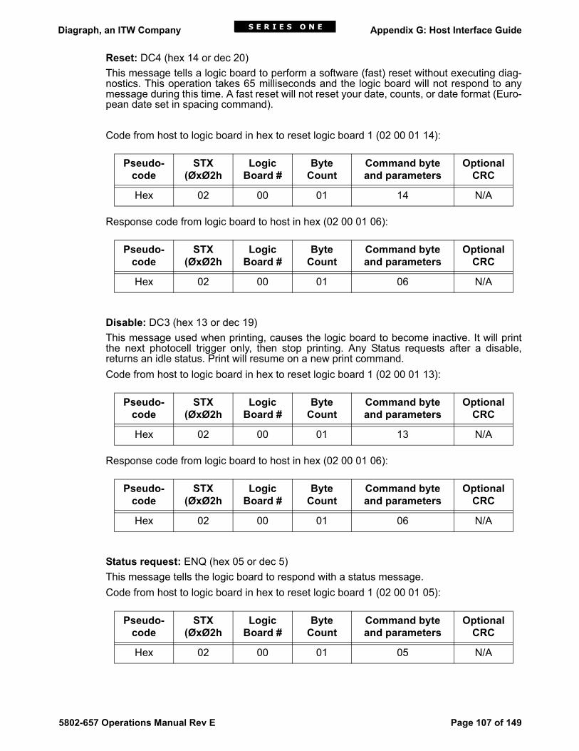
Diagraph, an ITW Company Appendix G: Host Interface Guide
5802-657 Operations Manual Rev E Page 107 of 149
Reset: DC4 (hex 14 or dec 20)This message tells a logic board to perform a software (fast) reset without executing diag-nostics. This operation takes 65 milliseconds and the logic board will not respond to anymessage during this time. A fast reset will not reset your date, counts, or date format (Euro-pean date set in spacing command).
Code from host to logic board in hex to reset logic board 1 (02 00 01 14):
Response code from logic board to host in hex (02 00 01 06):
Disable: DC3 (hex 13 or dec 19) This message used when printing, causes the logic board to become inactive. It will printthe next photocell trigger only, then stop printing. Any Status requests after a disable,returns an idle status. Print will resume on a new print command.Code from host to logic board in hex to reset logic board 1 (02 00 01 13):
Response code from logic board to host in hex (02 00 01 06):
Status request: ENQ (hex 05 or dec 5) This message tells the logic board to respond with a status message.Code from host to logic board in hex to reset logic board 1 (02 00 01 05):
Pseudo-code
STX(ØxØ2h
LogicBoard #
Byte Count
Command byte and parameters
Optional CRC
Hex 02 00 01 14 N/A
Pseudo-code
STX(ØxØ2h
LogicBoard #
Byte Count
Command byte and parameters
Optional CRC
Hex 02 00 01 06 N/A
Pseudo-code
STX(ØxØ2h
LogicBoard #
Byte Count
Command byte and parameters
Optional CRC
Hex 02 00 01 13 N/A
Pseudo-code
STX(ØxØ2h
LogicBoard #
Byte Count
Command byte and parameters
Optional CRC
Hex 02 00 01 06 N/A
Pseudo-code
STX(ØxØ2h
LogicBoard #
Byte Count
Command byte and parameters
Optional CRC
Hex 02 00 01 05 N/A

Diagraph, an ITW Company Appendix G: Host Interface Guide
Page 108 of 149 5802-657 Operations Manual Rev E
Response code from logic board to host in hex (02 00 0B 53 41 14 00 00 30 30 30 30 3031):
This is the response from a logic board just powered up with only power and communica-tions connected. The 53 or (S) is the return byte indicating a status return.The 41 and 14 are the status bytes.The 00 and 00 are the 2 byte return for line speed.The 30 30 30 30 30 31 or (000001) is the sequence count.For a full description of the status return, review the section on messages from the logicboard to the host.
Parameter request: DC2 (hex 12 or dec 18)This message tells a logic board to send the host its operating parameters, in a parametermessage.Code from host to logic board in hex to reset logic board 1 (02 00 01 12):
Response code from logic board to host in hex (02 00 05 50 38 04 03 08):
NOTE: The four bytes 38 04 03 08 = 0434 binary value of indent rotary switches (decimalvalue = 10.8"). Bytes 03 08 = character space and character width.
Print message once: DC1 (hex 11 or dec 17) followed by text.Use this message to only print on the next box. A new DC1 message is needed for eachbox. The text may include autocode fields, such as time, date and sequence number.When the message prints, the logic board will insert the correct values for the autocodes. If the first byte of the text is the control character, BEL (hex 07), the logic board will repeatthe previous text, updating any appropriate autocode fields.
Pseudo-code
STX(ØxØ2h
LogicBoard #
Byte Count
Command byte and parameters
Optional CRC
Hex 02 00 0B 53 4114 00 00 30 30 30 30 30 31
N/A
Pseudo-code
STX(ØxØ2h
LogicBoard #
Byte Count
Command byte and parameters
Optional CRC
Hex 02 00 01 12 N/A
Pseudo-code
STX(ØxØ2h
LogicBoard #
Byte Count
Command byte and parameters
Optional CRC
Hex 02 00 05 02 00 05 50 38 04 03 08
N/A

Diagraph, an ITW Company Appendix G: Host Interface Guide
5802-657 Operations Manual Rev E Page 109 of 149
Code from host to logic board in hex to reset logic board 1 (02 00 02 11 41):
Response code from logic board to host in hex (02 00 01 06):
This will cause the logic board to print the letter "A" on the next box only. "A" is hex 41.
Print every box: E (hex 45 or dec 69) followed by text. Use this message, similar to the DC1 message, to print on boxes. However, the logic boardwill print the text on every box without further commands from the host. If the text includesautocode fields such as, time, date, and sequence number, the logic board will insert thecorrect values for each box printed.Code from host to logic board in hex to reset logic board 1 (02 00 02 45 41):
Response code from logic board to host in hex (02 00 01 06):
This will cause the logic board to print the letter "A" on all boxes without any further actionsfrom the host. "A" is hex 41.
Set spacing: S (hex 53 or dec 83) with spacing parameters. Use this message to set the number of blank column spaces between two printing charac-ters and determine the width of the characters. It also sets the a flag for the European dateformat.Spacing is a byte value of the number of blank dot columns between characters.Thedefault is currently 3 (decimal).Width is a byte value of the distance between dot columns in.01 inch units. The defaultwidth is currently.08 inches or 8 (decimal).Options byte 1 and 2 are byte values that allow the host to set special options in the logicboard. By setting bit 0 in Option 1, the logic board will use the European form for printingvariable date fields. The remaining 15 bits are reserved for future use. To guarantee com-patibility with future logic board versions, all should be zero.
Pseudo-code
STX(ØxØ2h
LogicBoard #
Byte Count
Command byte and parameters
Optional CRC
Hex 02 00 02 11 41 N/A
Pseudo-code
STX(ØxØ2h
LogicBoard #
Byte Count
Command byte and parameters
Optional CRC
Hex 02 00 01 06 N/A
Pseudo-code
STX(ØxØ2h
LogicBoard #
Byte Count
Command byte and parameters
Optional CRC
Hex 02 00 02 45 41 N/A
Pseudo-code
STX(ØxØ2h
LogicBoard #
Byte Count
Command byte and parameters
Optional CRC
Hex 02 00 01 06 N/A

Diagraph, an ITW Company Appendix G: Host Interface Guide
Page 110 of 149 5802-657 Operations Manual Rev E
Code from host to logic board in hex to reset logic board 1 (02 00 05 53 09 04 01 00):
Response code from logic board to host in hex (02 00 01 06):
The above message will set the column width of a printing character to.09, the dot columnsbetween characters to 4 and the date autocodes to the European date format.
Set time /date: T (hex 54 or dec 84) H1 H2 M1 M2 J1 J2 J3 Y1 Y2 The host sends this message to set the current time and date in the logic board. All valuesare ASCII digits, high- order digits first.H1 and H2 are the hour of the day (00 to 23), M1 and M2 represent the minutes (00 to 59).Seconds are set to zero, upon receipt of this message. J1, J2, and J3 are the Julian dates(the day of the year from 001 to 366 (leap year)). Y1 and Y2 are the last two digits of theyear.It is recommended that this message be sent to ALL logic boards simultaneously (usinghex FF for the logic board ID #) to guarantee that all the logic boards on one line are prop-erly synchronized.NOTE: Remember that if you use address FF and no response comes back from any ofthe Controllers, you must poll for ACK.Code from host to logic board 1 in hex (02 00 0A 54 31 30 33 30 30 30 31 39 35):
Response code from logic board to host in hex (02 00 01 06):
The above message sets the time and date to 10:30 am Jan1, 1995.
Set sequence #: N (hex 4E or dec 78) N1 N2 N3 N4 N5 N6 The host sends this message to set the current box sequence number used in printing thesequence number variable field. N1 through N6 are six ASCII digits, with the most signifi-cant digit first. The logic board increments this value by one after printing each box.
Pseudo-code
STX(ØxØ2h
LogicBoard #
Byte Count
Command byte and parameters
Optional CRC
Hex 02 00 05 53 04 09 01 00 N/A
Pseudo-code
STX(ØxØ2h
LogicBoard #
Byte Count
Command byte and parameters
Optional CRC
Hex 02 00 01 06 N/A
Pseudo-code
STX(ØxØ2h
LogicBoard #
Byte Count
Command byte and parameters
Optional CRC
Hex 02 00 0A 54 31 30 33 30 30 30 31 39 35
N/A
Pseudo-code
STX(ØxØ2h
LogicBoard #
Byte Count
Command byte and parameters
Optional CRC
Hex 02 00 01 06 N/A

Diagraph, an ITW Company Appendix G: Host Interface Guide
5802-657 Operations Manual Rev E Page 111 of 149
Code from host to logic board 1 in hex (02 00 07 4E 30 30 30 30 30 31):
Response code from logic board to host in hex (02 00 01 06):
This will set the sequence count to 000001 so the next box to print will be "1" if using the{N} sequence count autocode. Setting the sequence to 000000, will print a "0" on the nextbox.
Acknowledge previous: A (hex 41 or dec 65)The logic boards will not directly acknowledge a message sent to ALL logic boards simulta-neously (using hex FF for the logic board ID#), because their replies might conflict on theshared RS-232 data line. After sending an ALL logic boards message, the host shouldquery each logic board individually using the "acknowledge previous" message. If the logicboard received an ALL logic boards message, which it has not yet acknowledged, it willrespond with an ACK (hex 6). Otherwise, it will return a NAK (hex 15).Code from host to logic board 1 in hex (02 00 01 41):
Response code from logic board to host in hex (02 00 01 06):
The above message will have a response of NAK (15 hex) if a previous message with theaddress FF was not received.
Font message F: (hex 46 or dec 70) [Reset Font] [Character definitions] A font defines the character set used when printing messages. The ROM on the logicboard contains a standard font. To print using another font, you must first download the fontto the logic board via a series of font messages. Any characters not updated by a font mes-sage will continue to use the previous font definition.Font messages share a common format. The first byte is the letter F (hex 46 or dec 70) fol-lowed by an optional "reset font" byte (hex FF or dec 255) and as many character defini-tions as will fit into the remainder of the message. The data portion of the message must beno longer than 100 (decimal) bytes. If the "reset font" byte is present, the logic board willreturn to the standard font defined in the on-board ROM, before the processing and char-
Pseudo-code
STX(ØxØ2h
LogicBoard #
Byte Count
Command byte and parameters
Optional CRC
Hex 02 00 07 4E 30 30 30 30 30 31
N/A
Pseudo-code
STX(ØxØ2h
LogicBoard #
Byte Count
Command byte and parameters
Optional CRC
Hex 02 00 01 06 N/A
Pseudo-code
STX(ØxØ2h
LogicBoard #
Byte Count
Command byte and parameters
Optional CRC
Hex 02 00 01 41 N/A
Pseudo-code
STX(ØxØ2h
LogicBoard #
Byte Count
Command byte and parameters
Optional CRC
Hex 02 00 01 06 N/A

Diagraph, an ITW Company Appendix G: Host Interface Guide
Page 112 of 149 5802-657 Operations Manual Rev E
acter definitions. A font message, with only a "reset font" byte will restore the standard font.A hardware or software logic board reset also causes the logic board to return to the stan-dard font defined.A character definition consists of the ASCII code for the character, followed by two bytes ofinformation for each column in the character. These bytes define which rows in that columnof the character, will fire an ink dot, or will not fire leaving a white space. A set bit repre-sents an ink dot. The rows are numbered from the top; the columns are ordered from left toright. Included in the two bytes is an end- of-character bit, which marks the last column in acharacter definition.The two column definition bytes are defined below:
Byte 1:MSBLSB0 - 0 - Row 1 - Row 3 - Row 5 - Row 7 - Row 9 - 0
Byte 2:MSBLSBEOC - 0 - Row 2 - Row 4 - Row 6 - Row 8 - 0 - 0
The EOC is 0, except for the last byte of the character definition.See the example font download below. (NOTE: Column 8 would have been 0E, 1C; how-ever, the last column must have the MSB bit set making 1C + MSB = 9C.
Description of column 1
Byte 1 = 00001110 = 0EByte 2 = 00011100 = 1C
Column Description
Byte 1 Byte 2
1 0E 1C
2 1E 1C
3 10 28
4 20 28
5 20 28
6 10 28
7 1E 1C
8 0E 9C
Row # 1 2 3 4 5 6 7 8 9
Column 1 0 0 0 1 1 1 1 1 1
Byte 1 0 0 0 0 1 1 1 0
Byte 2 0 0 0 1 1 1 0 0

Diagraph, an ITW Company Appendix G: Host Interface Guide
5802-657 Operations Manual Rev E Page 113 of 149
Code from host to logic board in hex to send this font to logic board 1 (02 00 12 46 42 0E1C 1E 1C 10 28 20 28 20 28 10 28 1E 1C 0E 9C):
Response code from logic board to host in hex (02 00 01 06):
This will download the "A" font created above to the letter "B" ( 42h ).
Additional Messages from Host to Logic Board
Acknowledge: ACK (hex 06 or dec 06) The logic board sends this command to acknowledge correct reception of a message,which requires no other response such as, a reset or disable message.
Non-acknowledge: NAK (hex 15 or dec 21)The logic board sends this message in response to an "acknowledge previous" requestfrom the host, if it has not received a message addressed to ALL logic boards (logic boardID# = hex FF or dec 255), or if it has already acknowledged the last such message.Code from host to logic board in hex to reset logic board 1 (02 00 01 14):
Response code from logic board to host in hex (02 00 01 06):
Pseudo-code
STX(ØxØ2h
LogicBoard #
Byte Count
Command byte and parameters
Optional CRC
Hex 02 00 12 46 42 0E 1C 1E 1C 10 28 20 28 20 28 10 28 1E 1C 0E 9C
N/A
Pseudo-code
STX(ØxØ2h
LogicBoard #
Byte Count
Command byte and parameters
Optional CRC
Hex 02 00 01 06 N/A
Function Hex Decimal Symbol Page
Acknowledge 06 6 ACK 21
Non-acknowledge 15 21 NACK 21
Status 53 83 S 22
Parameters 50 80 P 24
Pseudo-code
STX(ØxØ2h
LogicBoard #
Byte Count
Command byte and parameters
Optional CRC
Hex 02 00 01 14 N/A
Pseudo-code
STX(ØxØ2h
LogicBoard #
Byte Count
Command byte and parameters
Optional CRC
Hex 02 00 01 06 N/A

Diagraph, an ITW Company Appendix G: Host Interface Guide
Page 114 of 149 5802-657 Operations Manual Rev E
Status message: S (hex 53 or dec 83) Status 1, Status 2, Line speed, Sequence #.A logic board sends this message in response to a status request. It consists of the charac-ter S, followed by ten bytes of information in the following format:
Status byte 1:Error - Warning - Idle - Button - Prt every - Print - Dwnfnt - Ready
Error set if a condition exists which will prevent printing.Warning set if a condition exists which requires operator action to avoid becoming an
error.Idle set if logic board is in idle status (disabled).Button set if the message advance button on the logic board has been pressed since
status was last sent.Prt every set if the logic board is configured to print the same message on every box.Print set if the logic board is currently indenting or printing on a box.Dwnfnt set if the font printing is a downloaded font. Cleared if the font printing is the
resident font from ROM.Ready set if the logic board requires a new message to be loaded. This bit is set
after a print is initiated unless "print every box" is in effect.Status byte 2:Low Ink - Spare - Indenting - Line Stop - Purge - Time - Bad Msg - Box
Low ink set if the ink reservoir needs filling. If this bit is set, the WARNING bit in statusbyte 1 will also be set.
Indenting set if the logic board is currently indenting a box in preparation for printing.Line Stop set if pulses are not received from the encoder within a designated amount of
time. If this bit is set, the WARNING bit in status style byte 1 will also be set.Purge set if the logic board is currently purging.Time set if the host has not set the time and date since the logic board's last full
reset (power on or reset button pressed). Printing a message that containsvariable data with this bit set will result in the fields printing with questionsmarks (?) instead of numerals. The logic board will retain the time, date, andsequence number through a fast reset sequence (i.e., one initiated by thehost if the logic board is still operational). It is recommended that the hostalways send the time and date at system initialization. This bit then indicateswhen a logic board has gone through a full reset sequence.
Bad msg set if a box has been detected and the logic board cannot print because thehost has sent no text message, or the host has sent text containing a syntaxerror, such as a bad variable field specification. Note that the text will not beinterpreted until a box is detected, so this bit will not be set until then. If thisbit is set, the ERROR bit in status byte 1 will also be set.
Box detect set if a box has been detected but indenting or printing has not yet begun.
Line speed: Number of containers printed in the last 60 seconds (two-byte binary value,updated every 15 seconds).
Sequence number: Sequence number of the container to be printed after the NEXT boxdetect. This command generates six ASCII digits (most significant first), incremented afterthe message for each container, following the box detect.

Diagraph, an ITW Company Appendix G: Host Interface Guide
5802-657 Operations Manual Rev E Page 115 of 149
Parameter message: P (hex 50) followed by three parameters:Delay switch setting: current setting of the print delay (indentation) thumbwheel switches in0.01 inch units (2-byte binary).Character spacing: number of blank dot columns between adjacent characters (1-bytebinary).Character width: distance between print dot columns in 0.01 inch units (1-byte binary).NOTE: Whenever a two byte binary value is transmitted, the low order (least significant)byte is sent first, followed by the higher byte order.

Diagraph, an ITW Company Appendix G: Host Interface Guide
Page 116 of 149 5802-657 Operations Manual Rev E

Diagraph, an ITW Company Appendix H: Font Samples
5802-657 Operations Manual Rev E Page 117 of 149
Appendix H: Font Samples
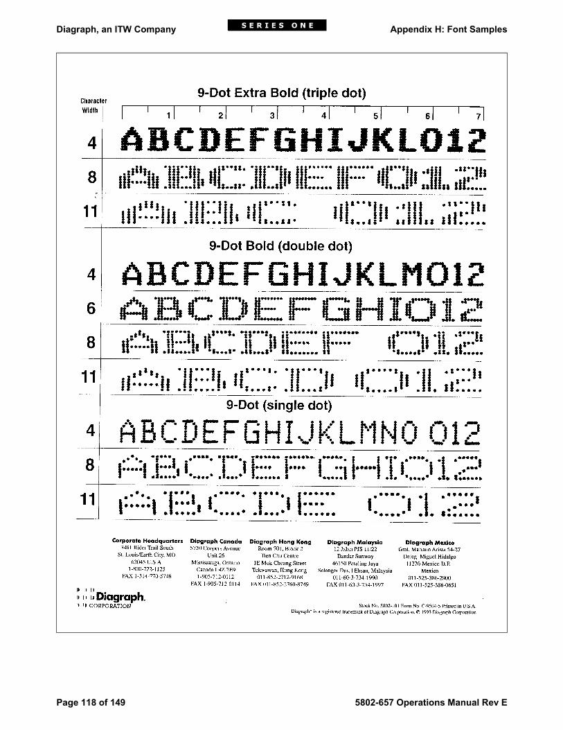
Diagraph, an ITW Company Appendix H: Font Samples
Page 118 of 149 5802-657 Operations Manual Rev E

Diagraph, an ITW Company Appendix H: Font Samples
5802-657 Operations Manual Rev E Page 119 of 149

Diagraph, an ITW Company Appendix H: Font Samples
Page 120 of 149 5802-657 Operations Manual Rev E

Diagraph, an ITW Company Appendix H: Font Samples
5802-657 Operations Manual Rev E Page 121 of 149

Diagraph, an ITW Company Appendix H: Font Samples
Page 122 of 149 5802-657 Operations Manual Rev E

Diagraph, an ITW Company Appendix I: Glossary of Terms
5802-657 Operations Manual Rev E Page 123 of 149
Appendix I: Glossary of TermsAccumulator - Housed within the IDS, theaccumulator stores ink for delivery to theprintheads.Autocode - A custom code entered into amessage to print a variable such as date,time, pallet count or plant location.Bracketry - Mounting hardware for ink jetsystem components.Broken Message - A message that is bro-ken into two or more pieces, usually fromthe encoder slipping.Check Valve - A valve that allows air or liq-uid to flow in only one direction.Columns Out of Alignment - Dot columnsline up in a zigzag pattern.COM - Abbreviation for a serial communi-cations port on a computer. Usuallyexpressed as "COM port" or associatedwith a number, "COM 1" or "COM 2".Conditioner - A non-pigmented ink solventdesigned for flushing and cleaning print-heads and ink line components.Controller - The heart of the ink jet system,this unit gathers information from the com-puter, the photosensor and the encoder,and facilitates the printing of messages bythe printheads.DIP Switches - A collection of smallswitches used to select options on a circuitboard. Dragging Type Dot Size Variation - Dotssmaller than average, at the beginning ofprint only.Dynamic Seepage - Ink seepage from ori-fices only during printing.Encoder - This device gathers line speedinformation via a wheel rolling against aconveyor belt. The controller uses thisinformation to determine when to send printsignals to the printheads.ESD - Electrostatic Discharge is a chargegenerated by separating or rubbingtogether two non-conductive materials.ESD can result in print problems or evendamage to the ink jet system. ESD Protection - Wrist straps, floor matsand other devices should be used whenhandling electronic components to mini-mize ESD.Ethernet Port Server - A communicationsstandard; connects asynchronous serialports to an unshielded twisted pair (UTP)
10BASE-T ethernet connection at a baudrate of 230 Kbps.Extra Dots - These are dots printed outsidethe designated dot columns.Font - A complete set of characters -alphabetic, numeric and punctuation - inone typeface. The font used in this glossaryis Arial.IDS - The Ink Delivery System consists of anumber of components working together totransfer ink from the ink pail to the printedproduct.Ink Filter - A 100-micron filter located inthe ink line to remove any impurities fromthe ink before it reaches the printhead.Ink Regulator - This component is locatedin the ink line close to the printhead and, inconjunction with the ink pressure gauge,can be adjusted to regulate ink pressure tothe printhead.Interface Board - The interface board pro-vides the interface between the logicboards and such external devices as theterminal, photosensor, encoder, printheads,etc.Internal Dot Size Variation - Dots are dif-ferent in size at the intersection of a dot col-umn and a dot row.Jumper - A small plug or wire that alters ahardware configuration by connecting dif-ferent points in an electronic circuit. LED - Light Emitting Diode. There are sev-eral LEDs in the Series 1 system, and theyeither illuminate or extinguish to indicatevarious operating conditions.Logic Board - The logic boards control allprinting and communication functions.Each logic board operates independentlyand controls one nine-dot printhead.MSDS - A Material Safety Data Sheet con-tains federally mandated safety, environ-mental and disposal information about anink or other potentially hazardous material.NEMA - National Electrical ManufacturersAssociation, a trade organization that setsperformance standards for the electricalindustry.Off Target Printing - One or more dots notprinted in the expected location in the char-acter.Photosensor -- A device that emits abeam of light, and sends a print signal to

Diagraph, an ITW Company Appendix I: Glossary of Terms
Page 124 of 149 5802-657 Operations Manual Rev E
the controller when light is reflected back toit by a product passing on a conveyor.Potentiometer - A variable voltage resistorthat can be adjusted with a small screw-driver to effect voltage changes in print-head solenoids.Pressure Gauge - This can be attached tothe ink line and used to measure ink pres-sure, aiding the operator in making adjust-ments to improve print quality.Print Indentation -The sum of two mea-surements: The distance from the photo-sensor to the center of the printhead, plusthe distance from the leading edge of theproduct to the start of printing.Printhead -- A solenoid-activated mecha-nism that propels ink droplets onto a mov-ing surface.
Printstation - One or more printheads setup to mark a given product in a specifiedlocation.psi - Pounds per Square Inch, a measureof pressure.Pulse Width - The amount of time a print-head solenoid is on, one of the factors con-trolling the size of a printed dot.RS-232 - Serial communication standardemployed by personal computers. Itdefines three types of connection (electri-cal, functional and mechanical) usuallyused with 25-pin D-shaped connectors. RS-422 - Serial communication standardwhich allows transmissions over long dis-tances at high speeds.

Diagraph, an ITW Company Reference Drawings
5802-657 Operations Manual Rev E Page 125 of 149
Reference DrawingsThe following pages contain three categories of drawings, with each category arranged innumerical order.
Controller DrawingsEleven Series 1 controller options.


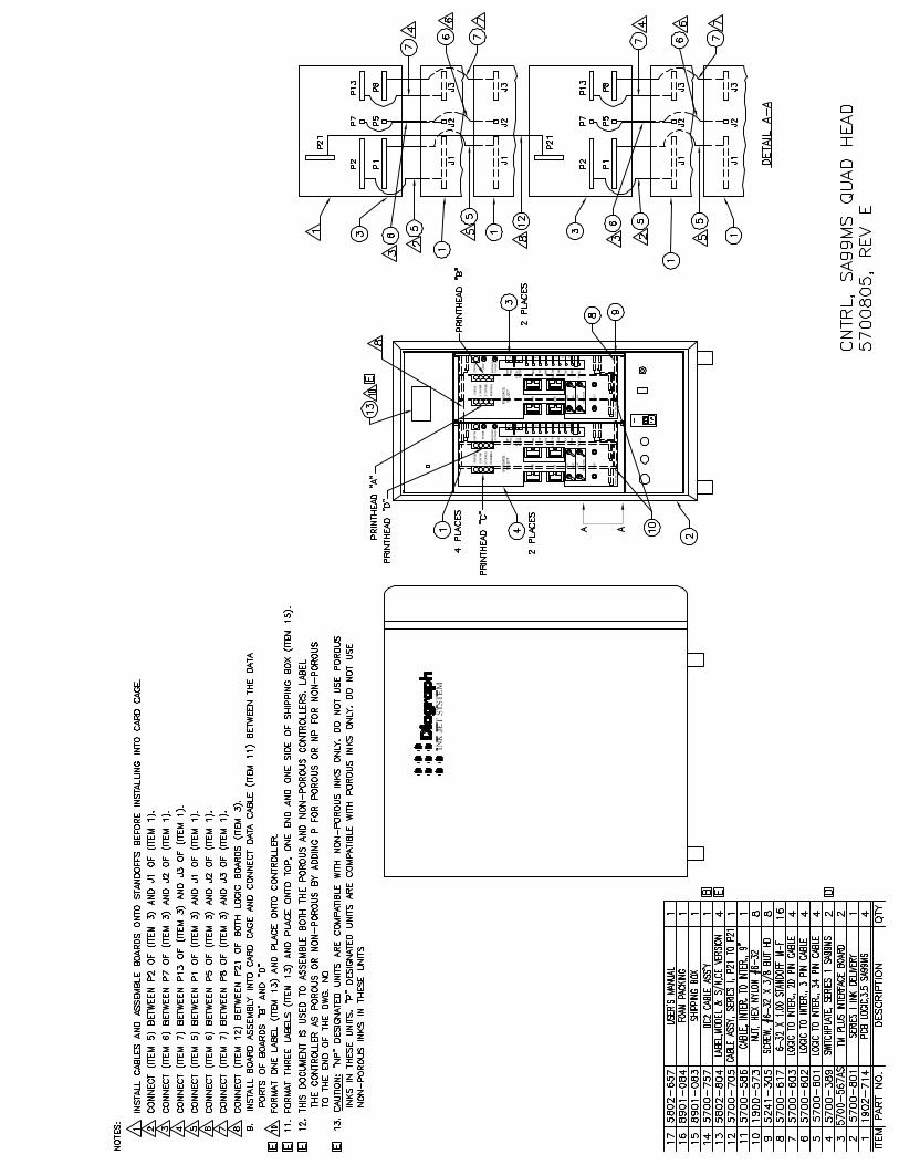


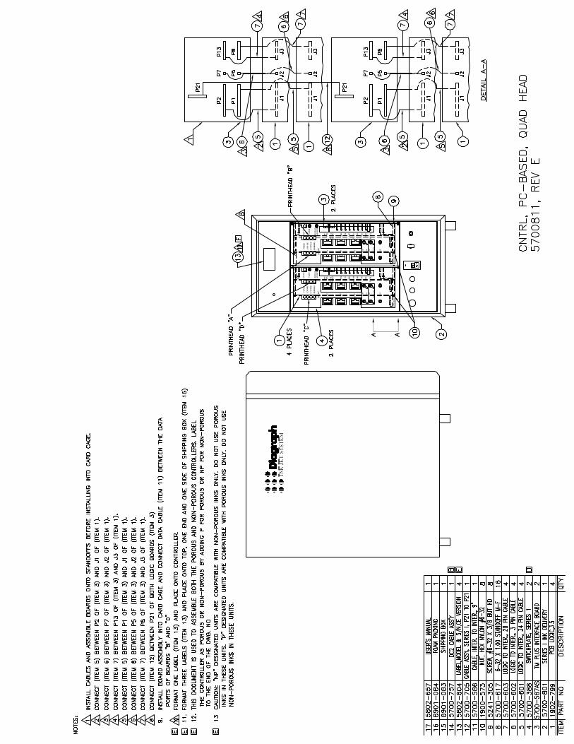


Diagraph, an ITW Company Reference Drawings
5802-657 Operations Manual Rev E Page 137 of 149
Controller Block DiagramsBlock diagrams of the 11 controller options.
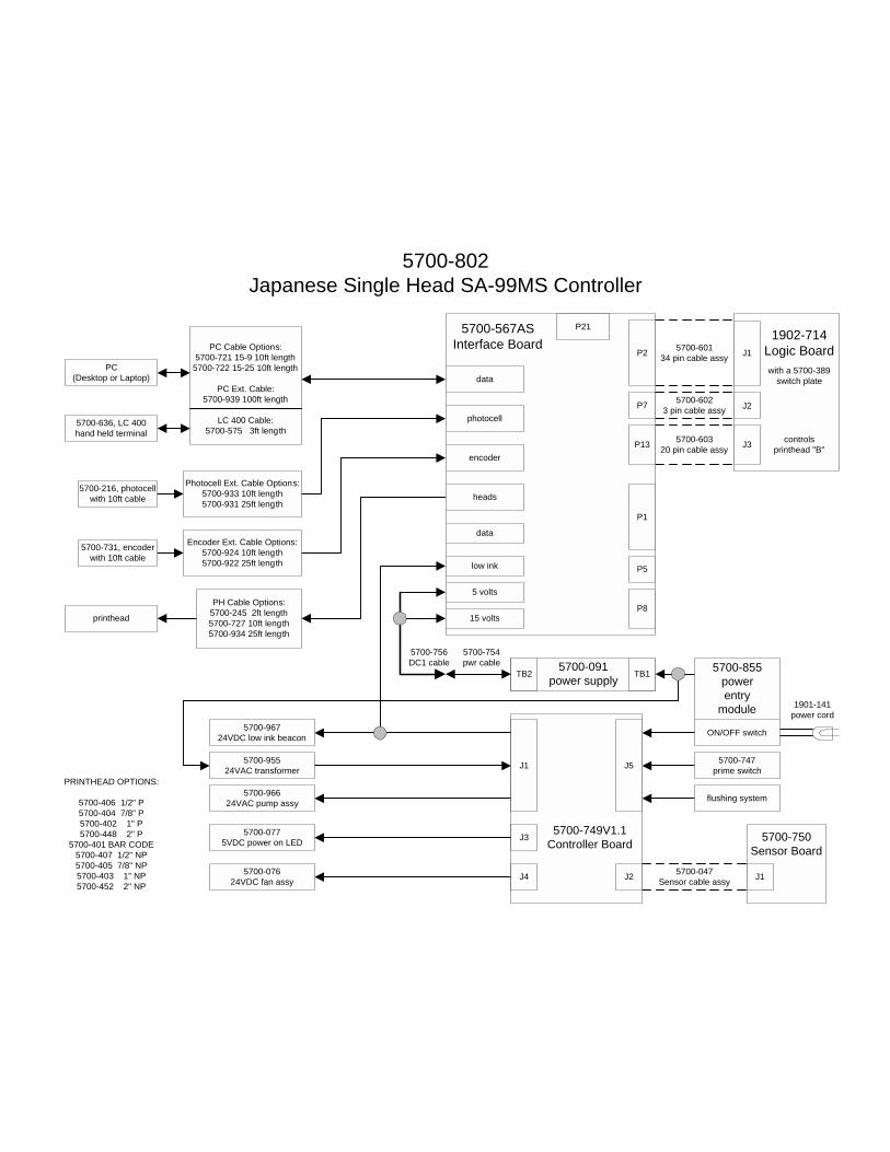
5700-802Japanese Single Head SA-99MS Controller
5700-6023 pin cable assy
5700-60134 pin cable assy
5700-60320 pin cable assy
5700-047Sensor cable assy
5700-567ASInterface Board
data
encoder
photocell
heads
P2
P7
P13
P1
P5
P815 volts
5 volts
low ink
data
P21
5700-749V1.1Controller Board
J2
J1
J3
J4
J5
5700-750Sensor Board
J1
5700-756DC1 cable
flushing system
5700-747prime switch
5700-96724VDC low ink beacon
5700-95524VAC transformer
5700-96624VAC pump assy
5700-0775VDC power on LED
5700-07624VDC fan assy
1901-141power cord
5700-855powerentry
module
ON/OFF switch
printhead
PRINTHEAD OPTIONS:
5700-406 1/2" P5700-404 7/8" P5700-402 1" P5700-448 2" P
5700-401 BAR CODE5700-407 1/2" NP5700-405 7/8" NP5700-403 1" NP5700-452 2" NP
PH Cable Options:5700-245 2ft length5700-727 10ft length5700-934 25ft length
5700-216, photocellwith 10ft cable
5700-731, encoderwith 10ft cable
Encoder Ext. Cable Options:5700-924 10ft length5700-922 25ft length
Photocell Ext. Cable Options:5700-933 10ft length5700-931 25ft length
PC(Desktop or Laptop)
5700-636, LC 400hand held terminal
PC Cable Options:5700-721 15-9 10ft length
5700-722 15-25 10ft length
PC Ext. Cable:5700-939 100ft length
LC 400 Cable:5700-575 3ft length
5700-091power supplyTB2 TB1
1902-714Logic BoardJ1
J2
J3 controlsprinthead "B"
with a 5700-389switch plate
5700-754pwr cable

5700-803Japanese Dual Head SA-99MS Controller
5700-6023 pin cable assy
5700-60134 pin cable assy
5700-60320 pin cable assy
5700-6023 pin cable assy
5700-60134 pin cable assy
5700-60320 pin cable assy
5700-047Sensor cable assy
5700-567ASInterface Board
data
encoder
photocell
heads
P2
P7
P13
P1
P5
P815 volts
5 volts
low ink
data
P21
5700-749V1.1Controller Board
J2
J1
J3
J4
J5
5700-750Sensor Board
J1
flushing system
5700-747prime switch
5700-96724VDC low ink beacon
5700-95524VAC transformer
5700-96624VAC pump assy
5700-0775VDC power on LED
5700-07624VDC fan assy
1901-141power cord
5700-855powerentry
module
ON/OFF switch
printhead
printhead
PRINTHEAD OPTIONS:
5700-406 1/2" P5700-404 7/8" P5700-402 1" P5700-448 2" P
5700-401 BAR CODE5700-407 1/2" NP5700-405 7/8" NP5700-403 1" NP5700-452 2" NP
PH Cable Options:5700-245 2ft length5700-727 10ft length5700-934 25ft length
PH Cable Options:5700-245 2ft length5700-727 10ft length5700-934 25ft length
5700-216, photocellwith 10ft cable
5700-731, encoderwith 10ft cable
Encoder Ext. Cable Options:5700-924 10ft length5700-922 25ft length
Photocell Ext. Cable Options:5700-933 10ft length5700-931 25ft length
PC(Desktop or Laptop)
5700-636, LC 400hand held terminal
PC Cable Options:5700-721 15-9 10ft length
5700-722 15-25 10ft length
PC Ext. Cable:5700-939 100ft length
LC 400 Cable:5700-575 3ft length
5700-091power supplyTB2 TB1
1902-714Logic BoardJ1
J2
J3 controlsprinthead "B"
with a 5700-389switch plate
1902-714Logic BoardJ1
J2
J3 controlsprinthead "A"
with a 5700-389switch plate
5700-756DC1 cable
5700-754pwr cable

5700-805Japanese Quad Head SA-99MS Controller
5700-6023 pin cable assy
5700-60134 pin cable assy
5700-60320 pin cable assy
5700-6023 pin cable assy
5700-60134 pin cable assy
5700-60320 pin cable assy
5700-047Sensor cable assy
5700-6023 pin cable assy
5700-60134 pin cable assy
5700-60320 pin cable assy
5700-6023 pin cable assy
5700-60134 pin cable assy
5700-60320 pin cable assy
5700-70510 pin
cable assy
5700-567ASInterface Board
data
encoder
photocell
heads
P2
P7
P13
P1
P5
P815 volts
5 volts
low ink
data
P21
5700-567ASInterface Board
data
encoder
photocell
heads
P2
P7
P13
P1
P5
P815 volts
5 volts
low ink
data
P21
5700-749V1.1Controller Board
J2
J1
J3
J4
J5
5700-750Sensor Board
J1
5700-586cable assy
flushing system
5700-747prime switch
5700-96724VDC low ink beacon
5700-95524VAC transformer
5700-96624VAC pump assy
5700-0775VDC power on LED
5700-07624VDC fan assy
1901-141power cord
5700-855powerentry
module
ON/OFF switch
printhead
printhead
printhead
printhead
PRINTHEAD OPTIONS:
5700-406 1/2" P5700-404 7/8" P5700-402 1" P5700-448 2" P
5700-401 BAR CODE5700-407 1/2" NP5700-405 7/8" NP5700-403 1" NP5700-452 2" NP
PH Cable Options:5700-245 2ft length5700-727 10ft length5700-934 25ft length
PH Cable Options:5700-245 2ft length5700-727 10ft length5700-934 25ft length
PH Cable Options:5700-245 2ft length5700-727 10ft length5700-934 25ft length
PH Cable Options:5700-245 2ft length5700-727 10ft length5700-934 25ft length
5700-216, photocellwith 10ft cable
5700-731, encoderwith 10ft cable
Encoder Ext. Cable Options:5700-924 10ft length5700-922 25ft length
Photocell Ext. Cable Options:5700-933 10ft length5700-931 25ft length
PC(Desktop or Laptop)
5700-636, LC 400hand held terminal
Encoder Ext. Cable Options:5700-924 10ft length5700-922 25ft length
PC Cable Options:5700-721 15-9 10ft length
5700-722 15-25 10ft length
PC Ext. Cable:5700-939 100ft length
LC 400 Cable:5700-575 3ft length
PHC - PHC Cable Options:(communications only)5700-708 10ft length5700-940 25ft length5700-941 50ft length5700-942 100ft length
PHC - PHC Cable Options:(communications only)5700-587 10ft length5700-943 25ft length5700-945 100ft length
5700-091power supplyTB2 TB1
5700-279gender changer
Photocell ExtensionCable Options:
5700-933 10ft length5700-931 25ft length
5700-280gender changer
TelemarkPrint HeadController
Series 1Print HeadController
1902-714Logic BoardJ1
J2
J3 controlsprinthead "B"
with a 5700-389switch plate
1902-714Logic BoardJ1
J2
J3 controlsprinthead "D"
with a 5700-389switch plate
1902-714Logic BoardJ1
J2
J3 controlsprinthead "C"
with a 5700-389switch plate
1902-714Logic BoardJ1
J2
J3 controlsprinthead "A"
with a 5700-389switch plate
5700-757DC2 cable
5700-754pwr cable

5700-807Japanese Quad Head SA-99MS Multi-tasking Controller
5700-6023 pin cable assy
5700-60134 pin cable assy
5700-60320 pin cable assy
5700-6023 pin cable assy
5700-60134 pin cable assy
5700-60320 pin cable assy
5700-047Sensor cable assy
5700-6023 pin cable assy
5700-60134 pin cable assy
5700-60320 pin cable assy
5700-6023 pin cable assy
5700-60134 pin cable assy
5700-60320 pin cable assy
5700-567ASInterface Board
data
encoder
photocell
heads
P2
P7
P13
P1
P5
P815 volts
5 volts
low ink
data
P21
5700-567ASInterface Board
data
encoder
photocell
heads
P2
P7
P13
P1
P5
P815 volts
5 volts
low ink
data
P21
5700-749V1.1Controller Board
J2
J1
J3
J4
J5
5700-750Sensor Board
J1
5700-586cable assy
flushing system
5700-747prime switch
5700-96724VDC low ink beacon
5700-95524VAC transformer
5700-96624VAC pump assy
5700-0775VDC power on LED
5700-07624VDC fan assy
1901-141power cord
5700-855powerentry
module
ON/OFF switch
printhead
printhead
printhead
printhead
PRINTHEAD OPTIONS:
5700-406 1/2" P5700-404 7/8" P5700-402 1" P5700-448 2" P
5700-401 BAR CODE5700-407 1/2" NP5700-405 7/8" NP5700-403 1" NP5700-452 2" NP
PH Cable Options:5700-245 2ft length5700-727 10ft length5700-934 25ft length
PH Cable Options:5700-245 2ft length5700-727 10ft length5700-934 25ft length
PH Cable Options:5700-245 2ft length5700-727 10ft length5700-934 25ft length
PH Cable Options:5700-245 2ft length5700-727 10ft length5700-934 25ft length
5700-216, photocellwith 10ft cable
5700-731, encoderwith 10ft cable
Encoder Ext. Cable Options:5700-924 10ft length5700-922 25ft length
Photocell Ext. Cable Options:5700-933 10ft length5700-931 25ft length
PC(Desktop or Laptop)
5700-636, LC 400hand held terminal
5700-216, photocellwith 10ft cable
5700-731, encoderwith 10ft cable
Encoder Ext. Cable Options:5700-924 10ft length5700-922 25ft length
Photocell Ext. Cable Options:5700-933 10ft length5700-931 25ft length
PC Cable Options:5700-721 15-9 10ft length
5700-722 15-25 10ft length
PC Ext. Cable:5700-939 100ft length
LC 400 Cable:5700-575 3ft length
Series 1 PHC
Telemark PHC
PHC - PHC Cable Options:(communications only)5700-708 10ft length5700-940 25ft length5700-941 50ft length5700-942 100ft length
PHC - PHC Cable Options:(communications only)5700-587 10ft length5700-943 25ft length5700-945 100ft length
1902-714Logic BoardJ1
J2
J3 controlsprinthead "D"
with a 5700-389switch plate
1902-714Logic BoardJ1
J2
J3 controlsprinthead "C"
with a 5700-389switch plate
1902-714Logic BoardJ1
J2
J3 controlsprinthead "B"
with a 5700-389switch plate
1902-714Logic BoardJ1
J2
J3 controlsprinthead "A"
with a 5700-389switch plate
5700-091power supplyTB2 TB1
5700-757DC2 cable
5700-754pwr cable

5700-808Japanese Single Head PC-Based Controller
5700-6023 pin cable assy
5700-60134 pin cable assy
5700-60320 pin cable assy
5700-047Sensor cable assy
5700-567ASInterface Board
data
encoder
photocell
heads
P2
P7
P13
P1
P5
P815 volts
5 volts
low ink
data
P21
5700-749V1.1Controller Board
J2
J1
J3
J4
J5
5700-750Sensor Board
J1
5700-756DC1 cable
flushing system
5700-747prime switch
5700-96724VDC low ink beacon
5700-95524VAC transformer
5700-96624VAC pump assy
5700-0775VDC power on LED
5700-07624VDC fan assy
1901-141power cord
5700-855powerentry
module
ON/OFF switch
printhead
PRINTHEAD OPTIONS:
5700-406 1/2" P5700-404 7/8" P5700-402 1" P5700-448 2" P
5700-401 BAR CODE5700-407 1/2" NP5700-405 7/8" NP5700-403 1" NP5700-452 2" NP
PH Cable Options:5700-245 2ft length5700-727 10ft length5700-934 25ft length
5700-216, photocellwith 10ft cable
5700-731, encoderwith 10ft cable
Encoder Ext. Cable Options:5700-924 10ft length5700-922 25ft length
Photocell Ext. Cable Options:5700-933 10ft length5700-931 25ft length
PC(Desktop or Laptop)
5700-636, LC 400hand held terminal
PC Cable Options:5700-721 15-9 10ft length
5700-722 15-25 10ft length
PC Ext. Cable:5700-939 100ft length
LC 400 Cable:5700-575 3ft length
5700-091power supplyTB2 TB1
1902-799Logic BoardJ1
J2
J3 controlsprinthead "B"
with a 5700-388switch plate
5700-754pwr cable

5700-811Japanese Quad Head PC-Based Controller
5700-6023 pin cable assy
5700-60134 pin cable assy
5700-60320 pin cable assy
5700-6023 pin cable assy
5700-60134 pin cable assy
5700-60320 pin cable assy
5700-047Sensor cable assy
5700-6023 pin cable assy
5700-60134 pin cable assy
5700-60320 pin cable assy
5700-6023 pin cable assy
5700-60134 pin cable assy
5700-60320 pin cable assy
5700-70510 pin
cable assy
5700-567ASInterface Board
data
encoder
photocell
heads
P2
P7
P13
P1
P5
P815 volts
5 volts
low ink
data
P21
5700-567ASInterface Board
data
encoder
photocell
heads
P2
P7
P13
P1
P5
P815 volts
5 volts
low ink
data
P21
5700-749V1.1Controller Board
J2
J1
J3
J4
J5
5700-750Sensor Board
J1
5700-586cable assy
5700-757DC2 cable
flushing system
5700-747prime switch
5700-96724VDC low ink beacon
5700-95524VAC transformer
5700-96624VAC pump assy
5700-0775VDC power on LED
5700-07624VDC fan assy
1901-141power cord
5700-855powerentry
module
ON/OFF switch
printhead
printhead
printhead
printhead
PRINTHEAD OPTIONS:
5700-406 1/2" P5700-404 7/8" P5700-402 1" P5700-448 2" P
5700-401 BAR CODE5700-407 1/2" NP5700-405 7/8" NP5700-403 1" NP5700-452 2" NP
PH Cable Options:5700-245 2ft length5700-727 10ft length5700-934 25ft length
PH Cable Options:5700-245 2ft length5700-727 10ft length5700-934 25ft length
PH Cable Options:5700-245 2ft length5700-727 10ft length5700-934 25ft length
PH Cable Options:5700-245 2ft length5700-727 10ft length5700-934 25ft length
5700-216, photocellwith 10ft cable
5700-731, encoderwith 10ft cable
Encoder Ext. Cable Options:5700-924 10ft length5700-922 25ft length
Photocell Ext. Cable Options:5700-933 10ft length5700-931 25ft length
PC(Desktop or Laptop)
5700-636, LC 400hand held terminal
Encoder Ext. Cable Options:5700-924 10ft length5700-922 25ft length
PC Cable Options:5700-721 15-9 10ft length
5700-722 15-25 10ft length
PC Ext. Cable:5700-939 100ft length
LC 400 Cable:5700-575 3ft length
PHC - PHC Cable Options:(communications only)5700-708 10ft length5700-940 25ft length5700-941 50ft length5700-942 100ft length
PHC - PHC Cable Options:(communications only)5700-587 10ft length5700-943 25ft length5700-945 100ft length
5700-091power supplyTB2 TB1
5700-279gender changer
Photocell ExtensionCable Options:
5700-933 10ft length5700-931 25ft length
5700-280gender changer
TelemarkPrint HeadController
Series 1Print HeadController
1902-799Logic BoardJ1
J2
J3 controlsprinthead "B"
with a 5700-388switch plate
1902-799Logic BoardJ1
J2
J3 controlsprinthead "A"
with a 5700-388switch plate
1902-799Logic BoardJ1
J2
J3 controlsprinthead "C"
with a 5700-388switch plate
1902-799Logic BoardJ1
J2
J3 controlsprinthead "D"
with a 5700-388switch plate
5700-754pwr cable
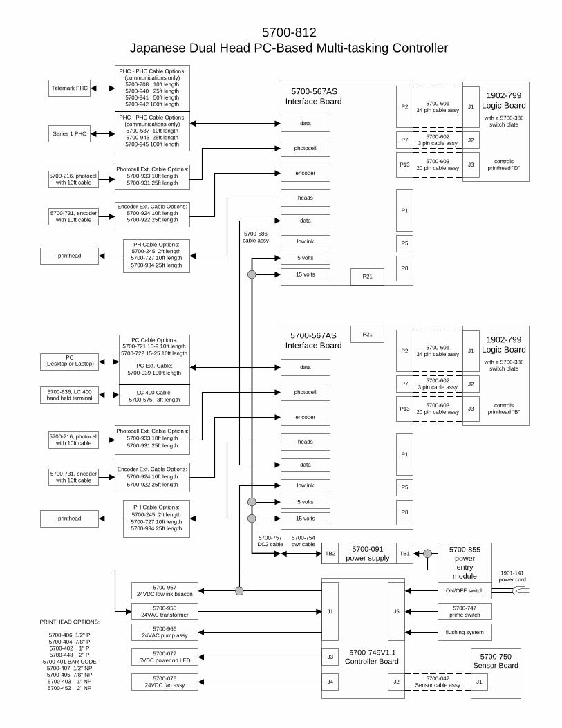
5700-812Japanese Dual Head PC-Based Multi-tasking Controller
5700-6023 pin cable assy
5700-60134 pin cable assy
5700-60320 pin cable assy
5700-047Sensor cable assy
5700-6023 pin cable assy
5700-60134 pin cable assy
5700-60320 pin cable assy
5700-567ASInterface Board
data
encoder
photocell
heads
P2
P7
P13
P1
P5
P815 volts
5 volts
low ink
data
P21
5700-567ASInterface Board
data
encoder
photocell
heads
P2
P7
P13
P1
P5
P815 volts
5 volts
low ink
data
P21
5700-749V1.1Controller Board
J2
J1
J3
J4
J5
5700-750Sensor Board
J1
5700-586cable assy
5700-757DC2 cable
flushing system
5700-747prime switch
5700-96724VDC low ink beacon
5700-95524VAC transformer
5700-96624VAC pump assy
5700-0775VDC power on LED
5700-07624VDC fan assy
1901-141power cord
5700-855powerentry
module
ON/OFF switch
printhead
printhead
PRINTHEAD OPTIONS:
5700-406 1/2" P5700-404 7/8" P5700-402 1" P5700-448 2" P
5700-401 BAR CODE5700-407 1/2" NP5700-405 7/8" NP5700-403 1" NP5700-452 2" NP
PH Cable Options:5700-245 2ft length5700-727 10ft length5700-934 25ft length
PH Cable Options:5700-245 2ft length5700-727 10ft length5700-934 25ft length
5700-216, photocellwith 10ft cable
5700-731, encoderwith 10ft cable
Encoder Ext. Cable Options:5700-924 10ft length5700-922 25ft length
Photocell Ext. Cable Options:5700-933 10ft length5700-931 25ft length
PC(Desktop or Laptop)
5700-636, LC 400hand held terminal
5700-216, photocellwith 10ft cable
5700-731, encoderwith 10ft cable
Encoder Ext. Cable Options:5700-924 10ft length5700-922 25ft length
Photocell Ext. Cable Options:5700-933 10ft length5700-931 25ft length
PC Cable Options:5700-721 15-9 10ft length
5700-722 15-25 10ft length
PC Ext. Cable:5700-939 100ft length
LC 400 Cable:5700-575 3ft length
Series 1 PHC
Telemark PHC
PHC - PHC Cable Options:(communications only)5700-708 10ft length5700-940 25ft length5700-941 50ft length5700-942 100ft length
PHC - PHC Cable Options:(communications only)5700-587 10ft length5700-943 25ft length5700-945 100ft length
5700-091power supplyTB2 TB1
1902-799Logic BoardJ1
J2
J3 controlsprinthead "B"
with a 5700-388switch plate
1902-799Logic BoardJ1
J2
J3 controlsprinthead "D"
with a 5700-388switch plate
5700-754pwr cable

5700-996Dual Head SA-99MS Controller
5700-6023 pin cable assy
5700-60134 pin cable assy
5700-60320 pin cable assy
5700-6023 pin cable assy
5700-60134 pin cable assy
5700-60320 pin cable assy
5700-047Sensor cable assy
5700-567ASInterface Board
data
encoder
photocell
heads
P2
P7
P13
P1
P5
P815 volts
5 volts
low ink
data
P21
5700-749V1.1Controller Board
J2
J1
J3
J4
J5
5700-750Sensor Board
J1
5700-756DC1 cable
flushing system
5700-747prime switch
5700-96724VDC low ink beacon
5700-95524VAC transformer
5700-96624VAC pump assy
5700-0775VDC power on LED
5700-07624VDC fan assy
1901-141power cord
5700-855powerentry
module
ON/OFF switch
printhead
printhead
PRINTHEAD OPTIONS:
5700-406 1/2" P5700-404 7/8" P5700-402 1" P5700-448 2" P
5700-401 BAR CODE5700-407 1/2" NP5700-405 7/8" NP5700-403 1" NP5700-452 2" NP
PH Cable Options:5700-245 2ft length5700-727 10ft length5700-934 25ft length
PH Cable Options:5700-245 2ft length5700-727 10ft length5700-934 25ft length
5700-216, photocellwith 10ft cable
5700-731, encoderwith 10ft cable
Encoder Ext. Cable Options:5700-924 10ft length5700-922 25ft length
Photocell Ext. Cable Options:5700-933 10ft length5700-931 25ft length
PC(Desktop or Laptop)
5700-636, LC 400hand held terminal
PC Cable Options:5700-721 15-9 10ft length
5700-722 15-25 10ft length
PC Ext. Cable:5700-939 100ft length
LC 400 Cable:5700-575 3ft length
5700-091power supplyTB2 TB1
1901-298Logic BoardJ1
J2
J3 controlsprinthead "B"
with a 5700-389switch plate
1901-298Logic BoardJ1
J2
J3 controlsprinthead "A"
with a 5700-389switch plate
5700-754pwr cable

5700-998Quad Head SA-99MS Controller
5700-6023 pin cable assy
5700-60134 pin cable assy
5700-60320 pin cable assy
5700-6023 pin cable assy
5700-60134 pin cable assy
5700-60320 pin cable assy
5700-047Sensor cable assy
5700-6023 pin cable assy
5700-60134 pin cable assy
5700-60320 pin cable assy
5700-6023 pin cable assy
5700-60134 pin cable assy
5700-60320 pin cable assy
5700-70510 pin
cable assy
5700-567ASInterface Board
data
encoder
photocell
heads
P2
P7
P13
P1
P5
P815 volts
5 volts
low ink
data
P21
5700-567ASInterface Board
data
encoder
photocell
heads
P2
P7
P13
P1
P5
P815 volts
5 volts
low ink
data
P21
5700-749V1.1Controller Board
J2
J1
J3
J4
J5
5700-750Sensor Board
J1
5700-586cable assy
5700-757DC2 cable
flushing system
5700-747prime switch
5700-96724VDC low ink beacon
5700-95524VAC transformer
5700-96624VAC pump assy
5700-0775VDC power on LED
5700-07624VDC fan assy
1901-141power cord
5700-855powerentry
module
ON/OFF switch
printhead
printhead
printhead
printhead
PRINTHEAD OPTIONS:
5700-406 1/2" P5700-404 7/8" P5700-402 1" P5700-448 2" P
5700-401 BAR CODE5700-407 1/2" NP5700-405 7/8" NP5700-403 1" NP5700-452 2" NP
PH Cable Options:5700-245 2ft length5700-727 10ft length5700-934 25ft length
PH Cable Options:5700-245 2ft length5700-727 10ft length5700-934 25ft length
PH Cable Options:5700-245 2ft length5700-727 10ft length5700-934 25ft length
PH Cable Options:5700-245 2ft length5700-727 10ft length5700-934 25ft length
5700-216, photocellwith 10ft cable
5700-731, encoderwith 10ft cable
Encoder Ext. Cable Options:5700-924 10ft length5700-922 25ft length
Photocell Ext. Cable Options:5700-933 10ft length5700-931 25ft length
PC(Desktop or Laptop)
5700-636, LC 400hand held terminal
Encoder Ext. Cable Options:5700-924 10ft length5700-922 25ft length
PC Cable Options:5700-721 15-9 10ft length
5700-722 15-25 10ft length
PC Ext. Cable:5700-939 100ft length
LC 400 Cable:5700-575 3ft length
PHC - PHC Cable Options:(communications only)5700-708 10ft length5700-940 25ft length5700-941 50ft length5700-942 100ft length
PHC - PHC Cable Options:(communications only)5700-587 10ft length5700-943 25ft length5700-945 100ft length
5700-091power supplyTB2 TB1
5700-279gender changer
Photocell ExtensionCable Options:
5700-933 10ft length5700-931 25ft length
5700-280gender changer
TelemarkPrint HeadController
Series 1Print HeadController
1901-298Logic BoardJ1
J2
J3 controlsprinthead "B"
with a 5700-389switch plate
1901-298Logic BoardJ1
J2
J3 controlsprinthead "D"
with a 5700-389switch plate
1901-298Logic BoardJ1
J2
J3 controlsprinthead "C"
with a 5700-389switch plate
1901-298Logic BoardJ1
J2
J3 controlsprinthead "A"
with a 5700-389switch plate
5700-754pwr cable
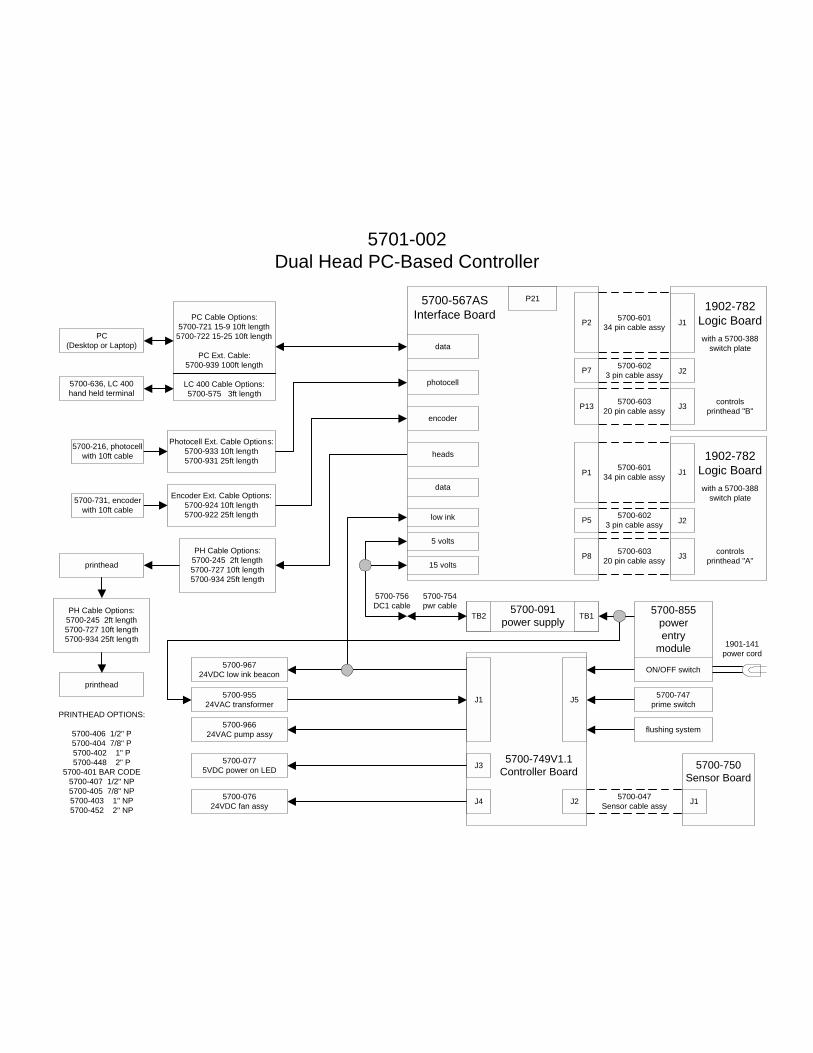
5701-002Dual Head PC-Based Controller
5700-6023 pin cable assy
5700-60134 pin cable assy
5700-60320 pin cable assy
5700-6023 pin cable assy
5700-60134 pin cable assy
5700-60320 pin cable assy
5700-047Sensor cable assy
5700-567ASInterface Board
data
encoder
photocell
heads
P2
P7
P13
P1
P5
P815 volts
5 volts
low ink
data
P21
5700-749V1.1Controller Board
J2
J1
J3
J4
J5
5700-750Sensor Board
J1
5700-756DC1 cable
flushing system
5700-747prime switch
5700-96724VDC low ink beacon
5700-95524VAC transformer
5700-96624VAC pump assy
5700-0775VDC power on LED
5700-07624VDC fan assy
1901-141power cord
5700-855powerentry
module
ON/OFF switch
printhead
printhead
PRINTHEAD OPTIONS:
5700-406 1/2" P5700-404 7/8" P5700-402 1" P5700-448 2" P
5700-401 BAR CODE5700-407 1/2" NP5700-405 7/8" NP5700-403 1" NP5700-452 2" NP
PH Cable Options:5700-245 2ft length5700-727 10ft length5700-934 25ft length
PH Cable Options:5700-245 2ft length5700-727 10ft length5700-934 25ft length
5700-216, photocellwith 10ft cable
5700-731, encoderwith 10ft cable
Encoder Ext. Cable Options:5700-924 10ft length5700-922 25ft length
Photocell Ext. Cable Options:5700-933 10ft length5700-931 25ft length
PC(Desktop or Laptop)
5700-636, LC 400hand held terminal
PC Cable Options:5700-721 15-9 10ft length
5700-722 15-25 10ft length
PC Ext. Cable:5700-939 100ft length
LC 400 Cable Options:5700-575 3ft length
5700-091power supplyTB2 TB1
1902-782Logic BoardJ1
J2
J3 controlsprinthead "B"
with a 5700-388switch plate
1902-782Logic BoardJ1
J2
J3 controlsprinthead "A"
with a 5700-388switch plate
5700-754pwr cable

5701-004Quad Head PC-Based Controller
5700-6023 pin cable assy
5700-60134 pin cable assy
5700-60320 pin cable assy
5700-6023 pin cable assy
5700-60134 pin cable assy
5700-60320 pin cable assy
5700-047Sensor cable assy
5700-6023 pin cable assy
5700-60134 pin cable assy
5700-60320 pin cable assy
5700-6023 pin cable assy
5700-60134 pin cable assy
5700-60320 pin cable assy
5700-70510 pin
cable assy
5700-567ASInterface Board
data
encoder
photocell
heads
P2
P7
P13
P1
P5
P815 volts
5 volts
low ink
data
P21
5700-567ASInterface Board
data
encoder
photocell
heads
P2
P7
P13
P1
P5
P815 volts
5 volts
low ink
data
P21
5700-749V1.1Controller Board
J2
J1
J3
J4
J5
5700-750Sensor Board
J1
5700-586cable assy
5700-757DC2 cable
flushing system
5700-747prime switch
5700-96724VDC low ink beacon
5700-95524VAC transformer
5700-96624VAC pump assy
5700-0775VDC power on LED
5700-07624VDC fan assy
1901-141power cord
5700-855powerentry
module
ON/OFF switch
printhead
printhead
printhead
printhead
PRINTHEAD OPTIONS:
5700-406 1/2" P5700-404 7/8" P5700-402 1" P5700-448 2" P
5700-401 BAR CODE5700-407 1/2" NP5700-405 7/8" NP5700-403 1" NP5700-452 2" NP
PH Cable Options:5700-245 2ft length5700-727 10ft length5700-934 25ft length
PH Cable Options:5700-245 2ft length5700-727 10ft length5700-934 25ft length
PH Cable Options:5700-245 2ft length5700-727 10ft length5700-934 25ft length
PH Cable Options:5700-245 2ft length5700-727 10ft length5700-934 25ft length
5700-216, photocellwith 10ft cable
5700-731, encoderwith 10ft cable
Encoder Ext. Cable Options:5700-924 10ft length5700-922 25ft length
Photocell Ext. Cable Options:5700-933 10ft length5700-931 25ft length
PC(Desktop or Laptop)
5700-636, LC 400hand held terminal
Encoder Ext. Cable Options:5700-924 10ft length5700-922 25ft length
PC Cable Options:5700-721 15-9 10ft length
5700-722 15-25 10ft length
PC Ext. Cable:5700-939 100ft length
LC 400 Cable:5700-575 3ft length
PHC - PHC Cable Options:(communications only)5700-708 10ft length5700-940 25ft length5700-941 50ft length5700-942 100ft length
PHC - PHC Cable Options:(communications only)5700-587 10ft length5700-943 25ft length5700-945 100ft length
5700-091power supplyTB2 TB1
5700-279gender changer
Photocell ExtensionCable Options:
5700-933 10ft length5700-931 25ft length
5700-280gender changer
TelemarkPrint HeadController
Series 1Print HeadController
1902-782Logic BoardJ1
J2
J3 controlsprinthead "D"
with a 5700-388switch plate
1902-782Logic BoardJ1
J2
J3 controlsprinthead "C"
with a 5700-388switch plate
1902-782Logic BoardJ1
J2
J3 controlsprinthead "B"
with a 5700-388switch plate
1902-782Logic BoardJ1
J2
J3 controlsprinthead "A"
with a 5700-388switch plate
5700-754pwr cable

Diagraph, an ITW Company Reference Drawings
5802-657 Operations Manual Rev E Page 149 of 149
Component Assembly DrawingsPictorials and assembly instructions for various Series 1 components.

WH
EN C
OPI
ED, D
OC
UM
ENT
IS N
OT
CO
NTR
OLL
ED B
Y D
IAG
RAP
H C
OR
POR
ATIO
N D
OC
UM
ENT
CO
NTR
OL.

CO
RPO
RA
TIO
N
WH
EN C
OPI
ED, D
OC
UM
ENT
IS N
OT
CO
NTR
OLL
ED B
Y D
IAG
RAP
H C
OR
POR
ATIO
N D
OC
UM
ENT
CO
NTR
OL

CO
RPO
RA
TIO
N
WH
EN C
OPI
ED, D
OC
UM
ENT
IS N
OT
CO
NTR
OLL
ED B
Y D
IAG
RAP
H C
OR
POR
ATIO
N D
OC
UM
ENT
CO
NTR
OL

CO
RPO
RA
TIO
NW
HEN
CO
PIED
, DO
CU
MEN
T IS
NO
T C
ON
TRO
LLED
BY
DIA
GR
APH
CO
RPO
RAT
ION
DO
CU
MEN
T C
ON
TRO
L

WH
EN C
OPI
ED, D
OC
UM
ENT
IS N
OT
CO
NTR
OLL
ED B
Y D
IAG
RAP
H C
OR
POR
ATIO
N D
OC
UM
ENT
CO
NTR
OL

WH
EN C
OPI
ED, D
OC
UM
ENT
IS N
OT
CO
NTR
OLL
ED B
Y D
IAG
RAP
H C
OR
POR
ATIO
N D
OC
UM
ENT
CO
NTR
OL

WH
EN C
OPI
ED, D
OC
UM
ENT
IS N
OT
CO
NTR
OLL
ED B
Y D
IAG
RAP
H C
OR
POR
ATIO
N D
OC
UM
ENT
CO
NTR
OL.

WH
EN C
OPI
ED, D
OC
UM
ENT
IS N
OT
CO
NTR
OLL
ED B
Y D
IAG
RAP
H C
OR
POR
ATIO
N D
OC
UM
ENT
CO
NTR
OL.

WH
EN C
OPI
ED, D
OC
UM
ENT
IS N
OT
CO
NTR
OLL
ED B
Y D
IAG
RAP
H C
OR
POR
ATIO
N D
OC
UM
ENT
CO
NTR
OL.

WH
EN C
OPI
ED, D
OC
UM
ENT
IS N
OT
CO
NTR
OLL
ED B
Y D
IAG
RAP
H C
OR
POR
ATIO
N D
OC
UM
ENT
CO
NTR
OL.

WH
EN C
OPI
ED, D
OC
UM
ENT
IS N
OT
CO
NTR
OLL
ED B
Y D
IAG
RAP
H C
OR
POR
ATIO
N D
OC
UM
ENT
CO
NTR
OL.

CO
RPO
RA
TIO
N
WH
EN C
OPI
ED, D
OC
UM
ENT
IS N
OT
CO
NTR
OLL
ED B
Y D
IAG
RAP
H C
OR
POR
ATIO
N D
OC
UM
ENT
CO
NTR
OL

CO
RPO
RA
TIO
N
WH
EN C
OPI
ED, D
OC
UM
ENT
IS N
OT
CO
NTR
OLL
ED B
Y D
IAG
RAP
H C
OR
POR
ATIO
N D
OC
UM
ENT
CO
NTR
OL

CO
RPO
RA
TIO
N
WH
EN C
OPI
ED, D
OC
UM
ENT
IS N
OT
CO
NTR
OLL
ED B
Y D
IAG
RAP
H C
OR
POR
ATIO
N D
OC
UM
ENT
CO
NTR
OL
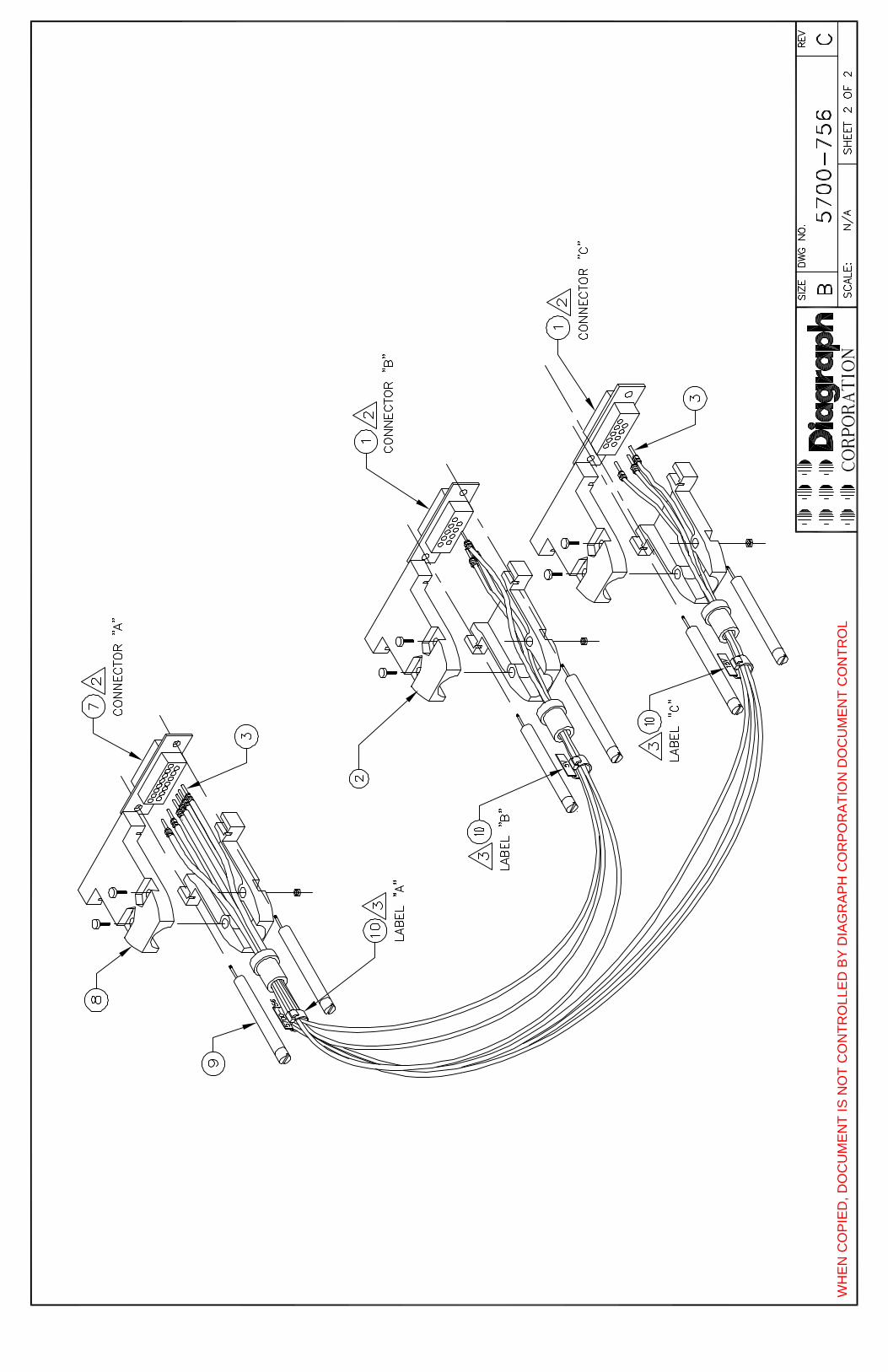
CO
RPO
RA
TIO
NW
HEN
CO
PIED
, DO
CU
MEN
T IS
NO
T C
ON
TRO
LLED
BY
DIA
GR
APH
CO
RPO
RAT
ION
DO
CU
MEN
T C
ON
TRO
L

CO
RPO
RA
TIO
N
WH
EN C
OPI
ED, D
OC
UM
ENT
IS N
OT
CO
NTR
OLL
ED B
Y D
IAG
RAP
H C
OR
POR
ATIO
N D
OC
UM
ENT
CO
NTR
OL

CO
RPO
RA
TIO
NW
HEN
CO
PIED
, DO
CU
MEN
T IS
NO
T C
ON
TRO
LLED
BY
DIA
GR
APH
CO
RPO
RAT
ION
DO
CU
MEN
T C
ON
TRO
L


CO
RPO
RA
TIO
N
WH
EN C
OPI
ED, D
OC
UM
ENT
IS N
OT
CO
NTR
OLL
ED B
Y D
IAG
RAP
H C
OR
POR
ATIO
N D
OC
UM
ENT
CO
NTR
OL

CO
RPO
RA
TIO
N
WH
EN C
OPI
ED, D
OC
UM
ENT
IS N
OT
CO
NTR
OLL
ED B
Y D
IAG
RAP
H C
OR
POR
ATIO
N D
OC
UM
ENT
CO
NTR
OL
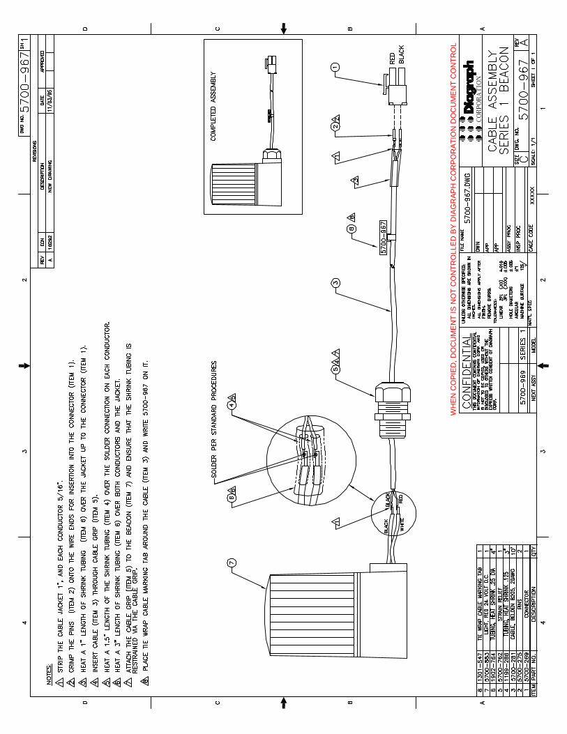
CO
RPO
RA
TIO
N
WH
EN C
OPI
ED, D
OC
UM
ENT
IS N
OT
CO
NTR
OLL
ED B
Y D
IAG
RAP
H C
OR
POR
ATIO
N D
OC
UM
ENT
CO
NTR
OL

CO
RPO
RA
TIO
N
WH
EN C
OPI
ED, D
OC
UM
ENT
IS N
OT
CO
NTR
OLL
ED B
Y D
IAG
RAP
H C
OR
POR
ATIO
N D
OC
UM
ENT
CO
NTR
OL