serial arithmetic techniques - ieee … arithmetic techniques ... parallel adder. the serial adder...
TRANSCRIPT
SERIAL ARITHMETIC TECHNIQUES
M. Lehman, D. Senzig and J. Lee IBM Watson Research Center Yorktown Heights, New York
SERIAL MODE MULTIPROCESSING
It has recently been suggested l that the association of serial-mode functional (arithmetic) units with multi-instruction counter, mUltiprocessing computing systems may result in highly efficient processing complexes. This follows from the fact of life that in going from parallel to serial realizations of various algorithms the hardware requirements fall much more rapidly than does the speed. Furthermore the speeds of the stower, serial, arithmetic units may be more closely matched to those of memory and to other parts of the system. Thus the need for extra control circuitry, for high-speed registers, queueing circuits and look-ahead control, for example, is reduced and the system's overall cost/performance ratio improved. For appropriate serial configurations then, performance may be improved relative to a parallel system when system costs are to be held constant. Reconfiguration of a fast parallel circuit, for example, can yield a number of slower seriat devices which, when kept busy, will increase throughput of the system.
The crux of the problem of optimizing throughput lies, of course, in the extent to which the large fast unit on the one hand and the several associated, slower, smaller units on the other can be kept busy; that is, their relative efficiency within an operating
715
computing environment. As previously demonstrated, 1
this consideration leads quite naturally to the multiprocessing configuration.
Recognizing that serial-mode operation may once again assume significance in the field of high-speed processing, we now wish to outline some appropriate algorithms. Thereby we hope to draw attention to techniques other than those currently considered during architectural, system and logical design activities. We shall not, however, in general, include detailed assessment of performance (speed and/or hardware) nor engage here in comparisons of serial and parallel devices. Such general comparative studies are meaningless when divorced from technologies and actual designs. Extrapolations from them to actual physical design situations are in general not valid and their usefulness is restricted to helping towards a deeper understanding of the various circuits and techniques discussed and compared.
BASIC CONCEPTS
Serial Operation
Traditionally a serial machine has been one operating on words,numbers, in a bit-by-bit fashion. We now intend to use the term to include bit-parallel, byte-serial, operation. Thus with a k-bit byte we may
From the collection of the Computer History Museum (www.computerhistory.org)
716 PROCEEDINGS - FALL JOINT COMPUTER CONFERENCE, 1965
conveniently regard the machine as operating radix 2k. We expect that the cost/performance ratio for the multiprocessing system considered, win be optimized for such serio-parallel operation. For the present discussion we consider 1 ~ k ~ 5. This range arises from timing and speed considerations which suggest, for example, that the basic radix 2k adder should be able to add two bytes in one bit-time as defined in the next section. Optimum k will then be determined mainly by the fan-in and fan-out of the logical elements being used.
Time
In conventional high-speed machines the absolute measure of speed is generally established in terms of the average, effective time delay t (nowadays in nanoseconds) experienced by a sign at or signal pattern in passing through a logical element or level. Naturally t will depend on the particular technology being used, that is, on the logical complexity of the element and on its fan-in and fan-out characteristics. Further, for a given product line t will spread over a range of values and the in-place de1'ay of a circuit will depend on its loading. However, we may use t symbolically to indicate speed, giving the duration of a specified operation to a first order of accuracy in terms of the number of logical levels its implementation requires.
In designing synchronous serial circuits it is not necessary or indeed desirable to synchronize signals at each logical level. Thus there emerges a new concept, the bit-time, tb, which represents the time inter-
val between clock signals.!.!!. then represents the max-t
imum number of logical circuits or levels between points at which clock signals are applied. A lower limit for tb arises from the maximum operating rate of a flip-flop (latch) assembled from, or at least equivalent to, two or more logical elements. In general, tb will exceed 2t and a practical operating range will be 2t ~ tb ~ 4t. Thus typically we may consider elements with a logical structure of complexity comparable to that of an AND/OR complex, with fan-in and fan-out in the range 5 to 10, an average delay of order Ins, and operating at a rate of order 3 X 108 bits per second, that is a bit time of order 3ns.
When discussing serial techniques we also make frequent use of the term "word-time" which in an n-bit binary machine generally refers to n bit-times.
In an ~ -byte, radix 2k system, processing the k-bit
bytes in parallel, the word-time witl be ~ bit-times.
Registers
The serial shift-register is a component whose ready availability is fundamental to the concept of serial operation. In the past these registers have usually taken a distributed, dynamic, transient form; delay lines (ultrasonic, magnetostrictive, electric) and magnetic drum circulating tracks all having been used. Discrete, static, permanent registers using tubes or transistors have, however, proved economicat, serving as both storage registers and shifting devices. With the second type of device it is simple to arrange for fully parallel input or output so that the register may also serve as a serial! parallel converter. This function is of importance in the general type of system where information is processed serially, in parallel, or in some more general mode, performance being optimized at each point in the system according to appropriate parameters of the· algorithm being implemented. Typically we might wish to read from memory in parallel but perform arithmetic on the extracted number byteserially.
The discrete, static shift-register appears to be the ideal candidate for realization in integrated or monolithic form when configurations larger than simple gates or adders are considered. Thus extensive use of its properties in systems design should prove rewarding. Its expected ready availability in the technologies of the future will in fact strongly reinforce the trend to increased use of bit-by-bit processing techniques.
SHIFTING
Shifting is a basic operation in its own right and is also an essential part of the synthesis of various other functions. In particular it may be required for alignment and fast normalization in floating-point operations and as an integral part of mUltiplication and division algorithms. Information stored in a shiftregister may be immediately shifted any number of places at a rate or order tb n's per bit or byte, a rate comparable to that of the parallel, cyclic shifter. In the most general circuit this shifting can occur in either direction. For more economical devices shift-
From the collection of the Computer History Museum (www.computerhistory.org)
SERIAL ARITHMETIC TECHNIQUES 717
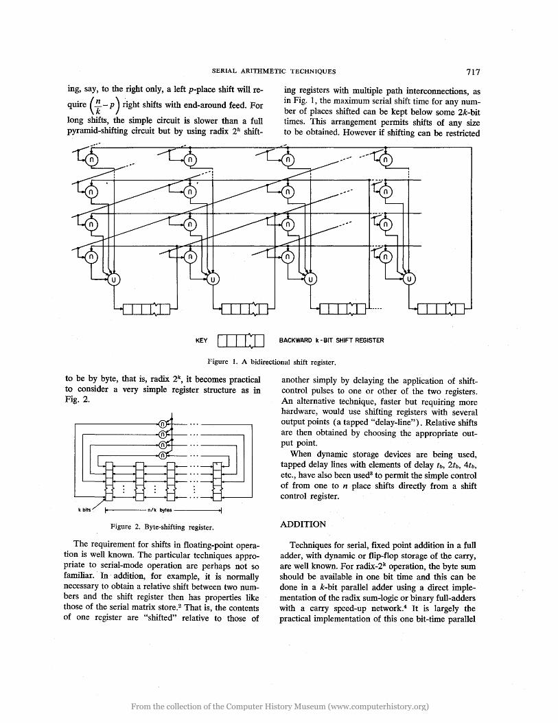
ing, say, to the right only, a left p-place shift will re
quire (~ - p ) ~ight shifts with end-around feed. For
long shifts, the simple circuit is slower than a full pyramid-shifting circuit but by using radix 2k shift-
KEY I I I IlJ
ing registers with mUltiple path interconnections, as in Fig. 1, the maximum serial shift time for any number of ptaces shifted can be kept below some 2k-bit times. This arrangement permits shifts of any size to be obtained. However if shifting can be restricted
BACKWARD k - BIT SHIFT REGISTER
Figure 1. A bidirectional shift register.
to be by byte, that is, radix 2k , it becomes practical to consider a very simple register structure as in Fig. 2.
Figure 2. Byte-shifting register.
The requirement for shifts in floating-point operation is well known. The particular techniques appropriate to serial-mode operation are perhaps not so familiar. In· addition, for example, it is normally necessary to obtain a relative shift between two numbers and the shift register then has properties like those of the serial matrix store.2 That is, the contents of one register are "shifted" relative to those of
another simply by delaying the application of shiftcontrol pulses to one or other of the two registers. An alternative technique, faster but requiring more hardware, would use shifting registers with several output points (a tapped "delay-line"). Relative shifts are then obtained by choosing the appropriate output point.
When dynamic storage devices are being used, tapped delay lines with elements of delay tb, 2tb, 4tb, etc., have also been used3 to permit the simple control of from one to n place shifts directly from a shift control register.
ADDITION
Techniques for serial, fixed point addition in a full adder, with dynamic or flip-flop storage of the carry, are well known. For radix-2k operation, the byte sum should be available in one bit time and this can be done in a k-bit parallel adder using a direct implementation of the radix sum-logic or binary full-adders with a carry speed-up network.4 It is largely the practical implementation of this one bit-time parallel
From the collection of the Computer History Museum (www.computerhistory.org)
718 PROCEEDINGS - FALL JOINT COMPUTER CONFERENCE, 1965
adder that ·determines an upper bound for k. The
f· d· . ddi . . ·11 b n b·· nt tb Ixe pomt a tIon tIme WI· e k It tImes or k . t
where~is the bit time to logic-level-delay ratio. This t
time must be compared with the time (1 + log2n)· t, a lower bound on the speed of any adder which follows from the result of Winograd.5 That is, the ratio of serial to parallel addition time will be less than
k(1 +~og2n)· t; . For example, if n, k and tb equal
50, 4 and 3 respectively, the serial by byte adder wili be less than 6.6 times as slow as the best possible parallel adder. The serial adder unit will require relatively less carry speed-up hardware (if any) than a single stage of the parallel unit so that the hardware ratio between paranel and serial devices will
be in excess of ~. Thus the cost/performance ratio of
the serial unit is considerably better than· that of the parallel device, an improvement which is maintained or even increased when floating-point adders, multipliers and dividers are considered.
Floating-point addition algorithms require the addition to be preceded by an exponent comparison and, where the exponents are unequal, a shift. Typical ranges for the exponents will require them to be represented by some eight bits or from one Jo three bytes. It may prove advantageous to process the exponents in a small parallel unit though the time penalty for processing serially will be small, only some two bit times, in the case of three byte exponents. The alignment shift will be obtained using one of the techniques described in the previous section. As shown there, no physical shifting of the operands need be performed and the size of the alignment will not significantly affect operation time.
Normalization of the sum obtained from a floating-point adder appears to be standard programming practice and in many machines normalized addition only is provided. This additional (micro) operation is time-consuming and appears to serve no useful purpose whatsoever. The present discussion will not pursue this point. 6 The authors could not, however, have reviewed techniques for serial normalization in connection with the addition operation without at least questioning its utility.
The most common technique for normalization shifts· the sum argument one bit or byte at a time until an indication is obtained that standard form
has been achieved. This cyclic procedure, widely used in both serial and parallel arithmetic units, is economical but slow and makes "the duration of additions operand dependent. Its use is, howeve,r, difficult to avoid in parallel units except through the provision of a large amount of extra hardware which may double the cost of the adder complex and also slow it down significantly. In serial units, however, a simple algorithm, used already in the Manchester Mark I computer,7 permits determination of the normalizing shift and hence the exponent increment during the actual adqition process. A counter is required which is reset initially and every time two neighboring sum bits are found to be unequal. Otherwise it is incremented by one during each bit time of the addition process, yielding immediately on its completion the shift number/ exp0:Ient increment. Use of the fast shifter then permits rapid completion of the floating-point addition.
An alternative, faster technique requires the provision of an additional register. As the sum output appears from the adder it is received in the conventional fashion by the sum register. A second register is connected by a parallel transfer mechanism to the sum register and receives its contents whenever the exponent increment counter is reset to zero, that is, whenever two succeeding sum bits are unequal. Thus on completion of the addition the normalized sum will appear in the second register and no further shifting is required.
MULTIPLICATION
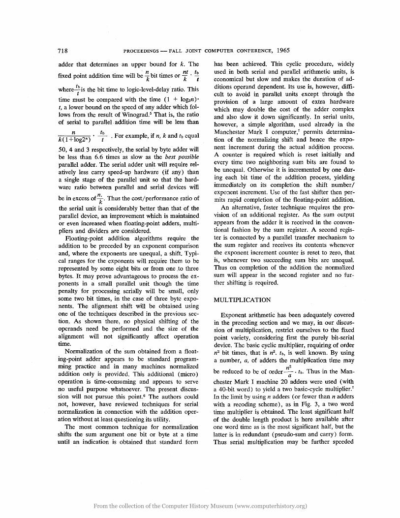
Exponent arithmetic has been adequately covered in the preceding section and we may, in our discussion of multiplication, restrict ourselves to the fixed point variety, considering first the purely bit-serial device. The basic cyclic multiplier, requiring of order n2 bit times, that is n2• tb, is well known. By using a number, a, of adders the multiplication time may
n2
be reduced to be of order-· tb. Thus in the Man-a
chester Mark I machine 20 adders were used (with a 40-bit word) to yield a two basic-cycle multiplier.7
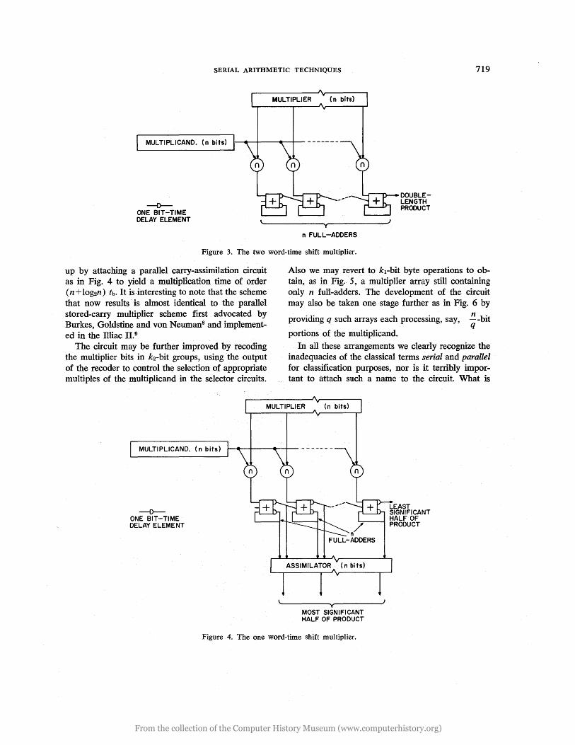
In the limit by using n adders (or fewer than n adders with a recoding scheme), as in Fig. 3, a two word time multiplier is obtained. The least significant half of the double length product is here available after one word time as is the most significant half, but the latter is in redundant (pseudo-sum and carry) form. Thus serial multiplication may be further speeded
From the collection of the Computer History Museum (www.computerhistory.org)
SERIAL ARITHMETIC TECHNIQUES 719
MULTIPLICAND. (n bits)
--0-ONE BIT-TIME DELAY ELEMENT
MULTIPLIER
y
n FULL-ADDERS
L...r"---'I'\..-.- DOUBLE
J
LENGTH PRODUCT
Figure 3. The two word-time shift multiplier.
up by attaching a parallel carry-assimilation circuit as in Fig. 4 to yield a multiplication time of order (n + lo~n) tb. It is· interesting to note that the scheme that now results is almost identical to the parallel stored-carry multiplier scheme first advocated by Burkes, Goldstine and von Neuman8 and imptemented in the llliac 11.9
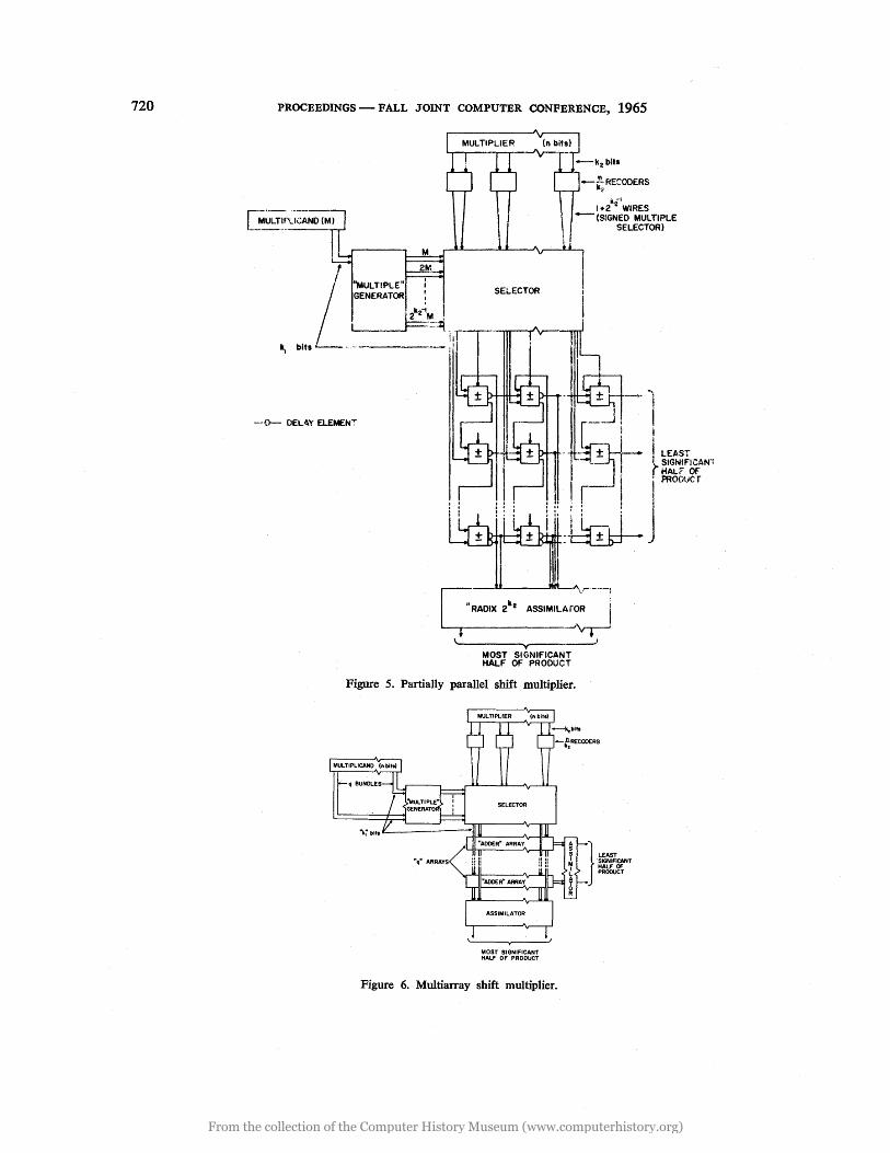
The circuit may be further improved by recoding the multiplier bits in k2-bit groups, using the output of the recoder to control the selection of appropriate multiples of the multiplicand in the selector circuits.
Also we may revert to k1-bit byte operations to obtain, as in Fig. 5, a multiplier array still containing only n futI-adders. The development of the circuit may also be taken one stage further as in Fig. 6 by
providing q such arrays each processing, say,
portions of the multiplicand.
!!-bit q
In all these arrangements we clearly recognize the inadequacies of the classical terms serial and parallel for classification purposes, nor is it terribly important to attach such a name to the circuit. What is
MULTIPLIER
MULTIPLICAND. (n bits)
--0-ONE BIT-TIME DELAY ELEMENT
~.-~---.~---------
n/ FULL-ADDERS
~------~y~------~
MOST SIGNIFICANT HALF OF PRODUCT
Figure 4. The one word-time shift multiplier.
From the collection of the Computer History Museum (www.computerhistory.org)
720 PROCEEDINGS - FALL JOINT COMPUTER CONFERENCE, 1965
/ ffiMM
GENERATOR : SELECTOR
-E~RE~ODERS
1+2i1i'
WIRES - (S:GNED MULTIPLE
SELECTOR)
L "MULTIPLE" I
~M I k, bits __ ,-I -----' ~::[:!rT
---{}- DELAY ELEMEN:
- +j .--<~ '\
~I~-. I 1 i
- - + - iLEAST' jlr- I SIGNIFICAN"
I '{HALr Of
I r-- I i PROOtiC r
, • I J :ikJ-II
~---_-a.a_-_.....J""--'\·-----l
"RADIX 2112 ASSIMILAiOR I '--1r-------.J~
~------~y ___ --_--' MOST SIGNIFICANT HALF OF PRODUCT
Figure 5. Partially parallel shift multiplier.
MOST SIGNIFICANT HALF OF PROOUCT
Figure 6. Multiarray shift mUltiplier.
}
LEAST SIGNIACANT HALF OF PROOUCT
From the collection of the Computer History Museum (www.computerhistory.org)
SERIAL ARITHMETIC TECHNIQUES 721
important is that by starting with a serial approach to multiplier design and by making use of the properties of synchronous, sequential operation in and with a shifting register, there has emerged a circuit whose. performance may, at much lower cost, approach that of the fully parallel inverted-pyramid multipliers.10,11,12 In the Appendix we quote some preliminary results for a multiplier design corresponding to the configuration of Fig. 5. These are compared with an iterative parallel multiplier designed to be of the same speed. These and other re.:. suIts substantiate a more general assessment that the cost/performance of the new configurations exceeds that of the parallel structures by a factor of between two and three.
DIVISION
The basic restoring and nonrestoring division techniques are inherently slow since they require a minimum of order n subtraction and/or addition cycles. They maybe supplemented by one or more of a number of speed-up techniques,13,14,15 but Freiman's analysis16 indicates that in practice these alone cannot yield a speed-up factor greater than about four.
We restrict ourselves therefore to a brief discussion of a technique previously17 outlined for decimal dividers. The technique is illustrative of a class of division methods which integrate readily with fast multiplier circuits to form efficient arithmetic units.
Consider a required remainderless division:
a Q=b 1 >Ibl ~ ~
Suppose a factor m could be determined such that mb = 1, then Q = ma. The algorithm to be described defines an iterative procedure for determining a sequencemi such that
bi 1T mi ~ 1
hence
both quadratically. Let
bo = b, = 2 + b,
We may write
-t -t
bo = 1 + 0 . 2 0 + E 2 0 -t
b>O b<O
1 > I 0 I ~ 2 0 or 0 . 1 > E ~ O.
Define
Consider
-t
mo = 1 - 0 . 2 0 -t 2t
= 2 - 2 0 [bo • 2 0]
b1 = mo bo -2t -3t
= 1 - (02 - E) 2 0 - 0 E 2 0
b1 deviates from one at least quadratically less than boo Generalizing we may thus define an iterative, convergent procedure
bi+l = mi bi
ti+l = 2ti -t t
mi+1 = 2 - 2 iTi [bi . 2 i+I]
to = 1
mo = 3/2
= 1/2
b>O b<O
This yields bi ~ 1, lli ~ Q to the accuracy of a, b in some 2 + [lOg2n] iterations.
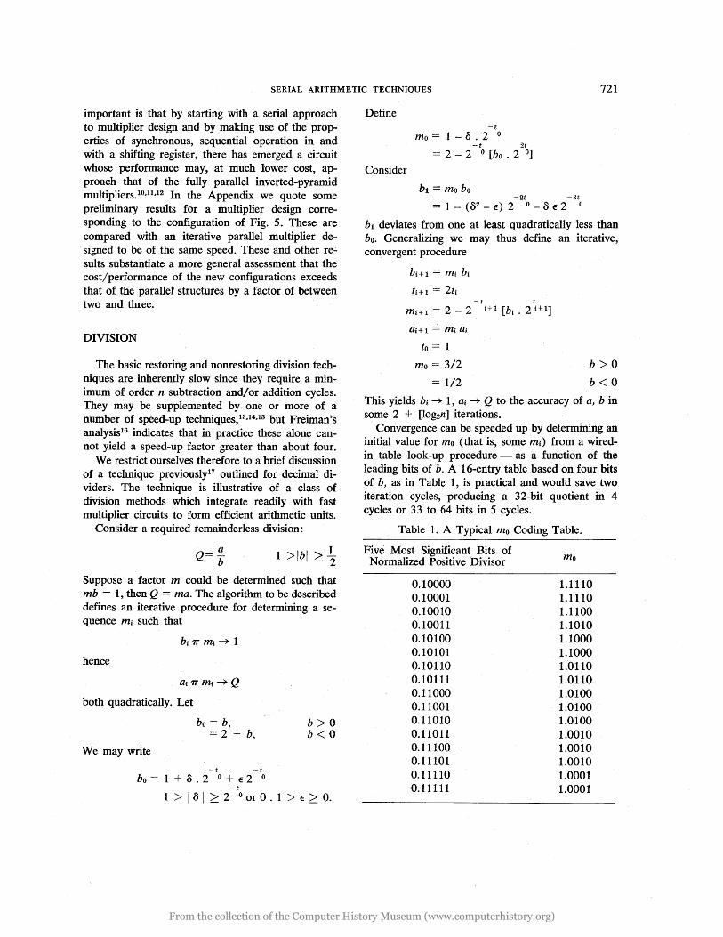
Convergence can be speeded up by determining an initial value for rno (that is, some mi) from a wiredin table look-up procedure - as a function of the leading bits of b. A 16-entry table based on four bits of b, as in Table 1, is practical and would save two iteration cycles, producing a 32-bit quotient in 4 cycles or 33 to 64 bits in 5 cycles.
Table 1. A Typical mo Coding Table.
Five Most Significant Bits of Normalized Positive Divisor
0.10000 0.10001 0.10010 0.10011 0.10100 0.10101 0.10110 0.10111 0.11000 0.11001 0.11010 0.11011 0.11100 0.11101 0.11110 0.11111
mo
1.1110 1.1110 1.1100 1.1010 1.1000 1.1000 1.0110 1.0110 1.0100 1.0100 1.0100 1.0010 1.0010 1.0010 1.0001 1.0001
From the collection of the Computer History Museum (www.computerhistory.org)
722 PROCEEDINGS - FALL JOINT COMPUTER CONFERENCE, 1965
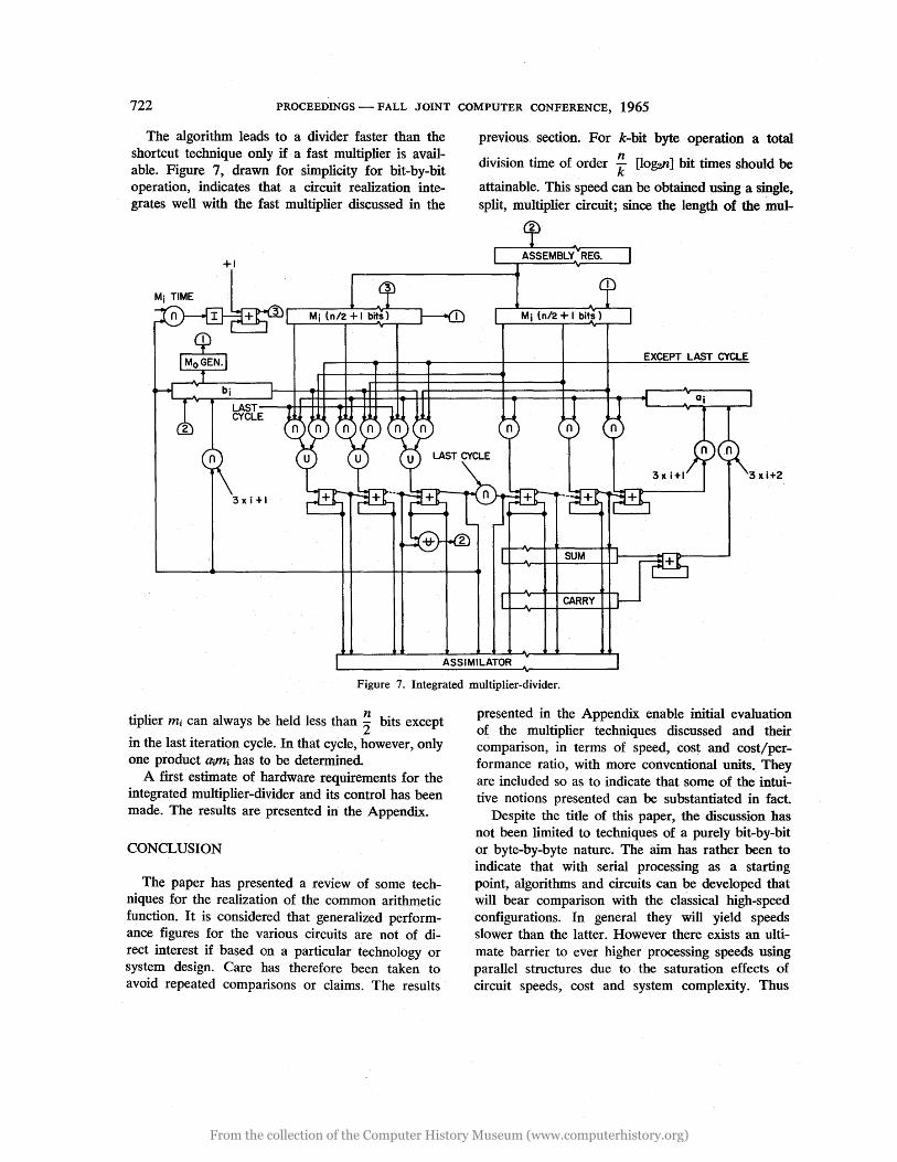
The algorithm leads to a divider faster than the shortcut technique only if a fast multiplier is available. Figure 7, drawn for simplicity for bit-by-bit operation, indicates that a circuit realization integrates well with the fast multiplier discussed in the
+1
3x i +1
previous section. For k-bit byte operation a total
division time of order !f [lo~n] bit times should be
attainable. This speed can be obtained. using a single, split, multiplier circuit; since the length of the mul-
Mj (n/2 + I bits)
EXCEPT LAST CYCLE
SUM
CARRY
ASSIMILATOR
Figure 7. Integrated multiplier-divider.
tiplier mi can always be held less than ~ bits except
in the last iteration cycle. In that cycle, however, only one product Q.;J'r4 has to be determined.
A first estimate of hardware requirements for the integrated multiplier-divider and its control has been made. The results are presented in the Appendix.
CONCLUSION
The paper has presented a review of some techniques for the realization of the common arithmetic function. It is considered that generalized performance figures for the various circuits are not of direct interest if based on a particular technology or system design. Care has therefore been taken to avoid . repeated comparisons or claims. The results
presented in the Appendix enable initial evaluation of the multiplier techniques discussed and their comparison, in terms of speed, cost and cost/performance ratio, with more conventional units. They are included so as to indicate that some of the intuitive notions presented can be substantiated in fact.
Despite the title of this paper, the discussion has not been limited to techniques of a purely bit-by-bit or byte-by-byte nature. The aim has rather been to indicate that with serial processing as a starting point, algorithms and circuits can be developed that will bear comparison with the classical high-speed configurations. In general they will yield speeds slower than the latter. However there exists an ultimate barrier to ever higher processing speeds using parallel structures due to the saturation effects of circuit speeds, cost and system complexity. Thus
From the collection of the Computer History Museum (www.computerhistory.org)
SERIAL ARITHMETIC TECHNIQUES 723
the use of techniques such as those described in a multiprocessing, multi-instruction counter configuration is believed capable of yielding performance and throughput superior to that of presently envisaged conventional systems.
In the past designers have, on the whole, pursued an· evolutionary path. With the very rapid development that has taken place in computer applications, in systems concepts and in technology it is, however, necessary from time to time to reexamine some of the more fundamental notions of machine structure. How, for example, should the fact that the cost of a monolithic, serial shift-register is likely to approach that of an individual flip-flop, with its input and output stages, affect systems structure? Decisions which were valid in 1947 are not necessarily valid in 1965 and concepts should not be rejected merely because they are unconventional or because they
MULTIPLICAND
have been rejected or abandoned in the past. In essence therefore this paper suggests and illustrates, with one example, what may be gained by fundamental rethinking in approaching the problellls of system and logical design.
APPENDIX
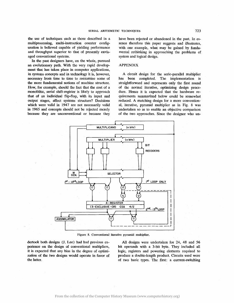
A circuit design for the serio-parallel multiplier has been completed. The implementation is straightforward and represents only the first round of the normal iterative, optimizing design procedure. Hence it is expected that the hardware requirements summarized below could be somewhat reduced. A matching design for a more conventional, iterative, pyramid multiplier as in Fig. 8 was undertaken so as to enable an objective comparison of the two approaches. Since the designer who un-
(n bits)
BIT
RECODERS
1st LOOP ONLY
---- ----------1 I I I
L...-____ -r-______ ..,.----s 2nd_ 13thLOOP I ~--~------------~ I
I I _______________ J
Figure 8. Conventional iterative pyramid multiplier.
dertook both designs (J. Lee) had had previous experience on the design of conventional multipliers, it is expected that any bias in the degree of optimization of the two designs would operate in favor of the latter.
All designs were undertaken for 24, 48 and 56 bit operands with a 3-bit byte. They included all logic, registers and powering elements required to produce a double-length product. Circuits used were of two basic types. The first: a current-switching
From the collection of the Computer History Museum (www.computerhistory.org)
724 PROCEEDINGS - FALL JOINT COMPUTER CONFERENCE, 1965
NOR/OR circuit with a fan-in of up to 4, a fan-out of lOon each of the 2 outputs and a direct connection (dotting) capability of 4 for either an additional AND or OR function. The second circuit, termed a spread-gate, yields functions, each of 3 out
of 6 input variables, on 4 outputs. Fan-out and dotting capabilities remain at 10 and 4 respectively.
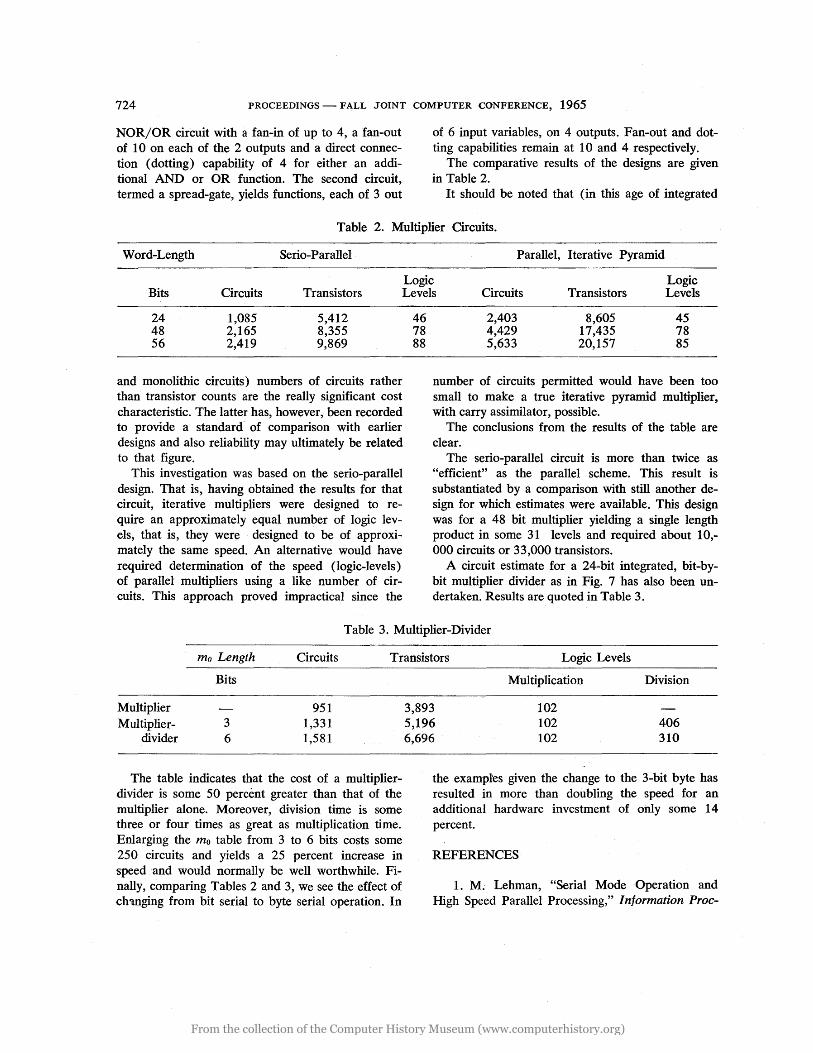
The comparative results of the designs are given in Table 2.
It should be noted that (in this age of integrated
Table 2. Multiplier Circuits.
Word-Length Serio-Parallel Parallel, Iterative Pyramid
Logic Logic Bits Circuits Transistors Levels Circuits Transistors Levels
24 1,085 5,412 48 2,165 8,355 56 2,419 9,869
and monolithic circuits) numbers of circuits rather than transistor counts are the really significant cost characteristic. The latter has, however, been recorded to provide a standard of comparison with earlier designs and also reliability may ultimately be related to that figure.
This investigation was based on the serio-parallel design. That is, having obtained the results for that circuit, iterative multipliers were designed to require an approximately equal number of logic levels, that is, they were designed to be of approximately the same speed. An alternative would have required determination of the speed (logic-levels) of parallel multipliers using a like number of circuits. This approach proved impractical since the
46 78 88
2,403 8,605 45 4,429 17,435 78 5,633 20,157 85
number of circuits permitted would have been too small to make a true iterative pyramid multiplier, with carry assimilator, possible.
The conclusions from the results of the table are clear.
The serio-parallel circuit is more than twice as "efficient" as the parallel scheme. This result is substantiated by a comparison with still another design for which estimates were available. This design was for a 48 bit multiplier yielding a single length product in some 31 levels and required about 10,-000 circuits or 33,000 transistors.
A circuit estimate for a 24-bit integrated, bit-bybit multiplier divider as in Fig. 7 has also been undertaken. Results are quoted in Table 3.
Table 3. Multiplier-Divider
ma Length Circuits Transistors Logic Levels
Bits
Multiplier 951 Multiplier- 3 1,331
divider 6 1,581
The table indicates that the cost of a multiplierdivider is some 50 percent greater than that of the mUltiplier alone. Moreover, division time is some three or four times as great as multiplication time. Enlarging the mo table from 3 to 6 bits costs some 250 circuits and yields a 25 percent increase in speed and would normally be well worthwhile. Finally, comparing Tables 2 and 3, we see the effect of ch'inging from bit serial to byte serial operation. In
Multiplication Division
3,893 102 5,196 102 406 6,696 102 310
the examples given the change to the 3-bit byte has resulted in more than doubling the speed for an additional hardware investment of only some 14 percent.
REFERENCES
1. M. Lehman, "Serial Mode Operation and High Speed Parallel Processing," Information Proc-
From the collection of the Computer History Museum (www.computerhistory.org)
SERIAL ARITHMETIC TECHNIQUES 725
essing 1965, Proceedings of IFIP Congress 65, part 2, New York (in press).
2. , "Serial Matrix Storage Systems," IRE Trans. on Electronic Computers, vol. EC-10, pp. 247-252 (June 1961).
3. K. Lonsdale and E. T. Warburton, "Mercury, A High-Speed Digital Computer," Proc. IEEE, suppl. no. 2 (Digital Computer Techniques), vol. 103, part B, pp. 174-183 (Apr. 1956).
4. M. Lehman, "A Comparative Study of Propagative Speed-Up Circuits in Binary Arithmetic Units," Information Processing 1962, Proceedings of IFIP Congress 62, North Holland Publishing Co., Amsterdam, 1963, pp. 671-677.
5. S. Winograd, "On the Time Required to Perform Addition," J. Assoc. Compo Mach., vol. 12, no. 1, pp. 277-285 (Apr. 1965).
6. R. L. Ashenhurst and N. Metropolis, "Unnormalized Floating Point Arithmetic," J. Assoc. Compo Mach.; vol. 6, no. 3, pp. 415-428 (July 1959).
7. T. Kilburn et aI, "Digital Computers at Manchester University," Proc. IEEE, part 2, vol. 100, pp. 487-500 (1953).
8. A. W. Burkes, H. H. Goldstine and J. von Neuman, "Preliminary Discussion of the Logical Design of an Electronic Computing Instrument," part 1, Institute of Advanced Study, Princeton, N. J., 1947.
9. D. J. Wheeler, "The Arithmetic Unit," University of Illinois, Digital Computer Laboratory, Report No. 92 (1959).
10. E. Bloch, "The Central Processing Unit," Planning a Computer System, W. Bucholz, ed., McGraw-Hill, New York, 1962, chap. 14.
11. C. S. Wallace, "A Suggestion for a Fast Multiplier," IEEE Trans. on Electronic Computers, vol. EC-13, pp. 14-17 (Feb. 1964).
12. T. Lamdan, "Some Aspects of the Design of a Simultaneous Multiplier for a Parallel Binary Digital Computer," Ph.D. Thesis, University of Manchester, 1963.
13. M. Lehman, "Parallel Arithmetic Units and Their Control," Ph.D. Thesis, London University, Feb. 1957.
14. K. D. Tocher, "Techniques of Multiplication and Division for Automatic Binary Computers," Journ. Mech. Appl. Math., Aug. 1958, pp. 364-384.
15. J. E. Robertson, "A New Class of Digital Division Methods," IRE Trans. on Electronic Computers, vol. EC-7, pp. 218-222 (Sept. 1958).
16. C. V. Freiman, "Statistical Analysis of Certain Binary Division Techniques," Proc. IRE, vol. 49, no. 1, pp. 91-103 (Jan. 1961).
17. R. K. Richards, "Arithmetic Operations in Digital Computers," Van Nostrand, Princeton, N.J., 1955, pp. 279-282.
From the collection of the Computer History Museum (www.computerhistory.org)

From the collection of the Computer History Museum (www.computerhistory.org)