september 23, 2015 - c.ymcdn.com · concentrated into 5,000 scfm oxidizer) limited to ambient...
TRANSCRIPT

September 23, 2015

VOC Sources
>3 VOC CompoundsRecovery/Reuse
Not Feasible
Thermal OxidizersCatalytic Oxidizers
Adsorbers
≤ 3 VOC CompoundsRecovery/Reuse not
Feasible
AdsorbersThermal OxidizersCatalytic Oxidizers
≤ 3 VOC CompoundsRecovery/Reuse
Feasible
Adsorbers

VOC
Concentration
(%LEL*)
Technology Options Typical Flow Thermal
Efficiency
(%)
0 - 10 Regenerative Thermal
or Catalytic Oxidation
(RTO / RCO)
80 - 97
0 – 10 Adsorption 0
10 - 40 Recuperative Thermal
or Catalytic Oxidation
or RTO
50 - 95
>40 Afterburner 0
*LEL = Lower Explosive Limit
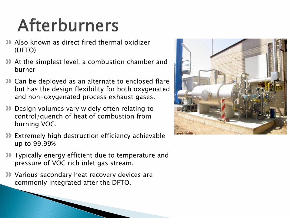
Also known as direct fired thermal oxidizer (DFTO)
At the simplest level, a combustion chamber and burner
Can be deployed as an alternate to enclosed flare but has the design flexibility for both oxygenated and non-oxygenated process exhaust gases.
Design volumes vary widely often relating to control/quench of heat of combustion from burning VOC.
Extremely high destruction efficiency achievable up to 99.99%
Typically energy efficient due to temperature and pressure of VOC rich inlet gas stream.
Various secondary heat recovery devices are commonly integrated after the DFTO.

After an analysis of the process exhaust gases, they have to be assigned to an ex-classified zone: 0 – 2
Secondary explosion relief measures are:
Static safeguards such as deflagration arresters and flame arresters
Fluid flame arresters
Backflash-safe injection into combustion chamber
Analytical surveillance
Explosive Process Gas Applications
Exhaust
gas
Zone 0
Compres
sed air
Residual
liquid
N2
Combustion
air
PC
PC
PI
PI
PSA_
PSA_
PDIA+
PICscM
TSA+
FIC
Natural
gas
PC
PI
PSA_FIC
sc
M
TSA+
PC
PIC TIC
FIC
Exhaust
gas
Zone 1
N2
PIPDIA+
TSA+
PC
PDIA+
TSA+
1.000-1.200 °C

Combustion chamber
SNCR*-stage
Steam boiler Quench Scrubber Demister
Waste water treatment Adsorption Stack
SCR**-stageDedioxi-nation
Exhaust gas/air
Fuel
Steam
Water supply
Reduction agent
Chemicals
Chemicals
Residual materials
Reduction agent
Sorptionagent
Waste water
X
X X X X X X X X
X X X
X X X X X X X
X X X X X X X
X X X X X X X
X X X X X X X
X
X
Organic solvents
Halogenated compounds
Compounds containig nitrogen
Sulphurous compounds
Heavy metals, e.g. mercury
Other liquids containing salts
Liquids containing particles (ash)
Liquid residue
Combustion air
Fields of Application

......many configurations
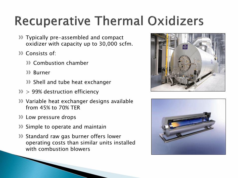
Typically pre-assembled and compact oxidizer with capacity up to 30,000 scfm.
Consists of:
Combustion chamber
Burner
Shell and tube heat exchanger
> 99% destruction efficiency
Variable heat exchanger designs available from 45% to 70% TER
Low pressure drops
Simple to operate and maintain
Standard raw gas burner offers lower operating costs than similar units installed with combustion blowers
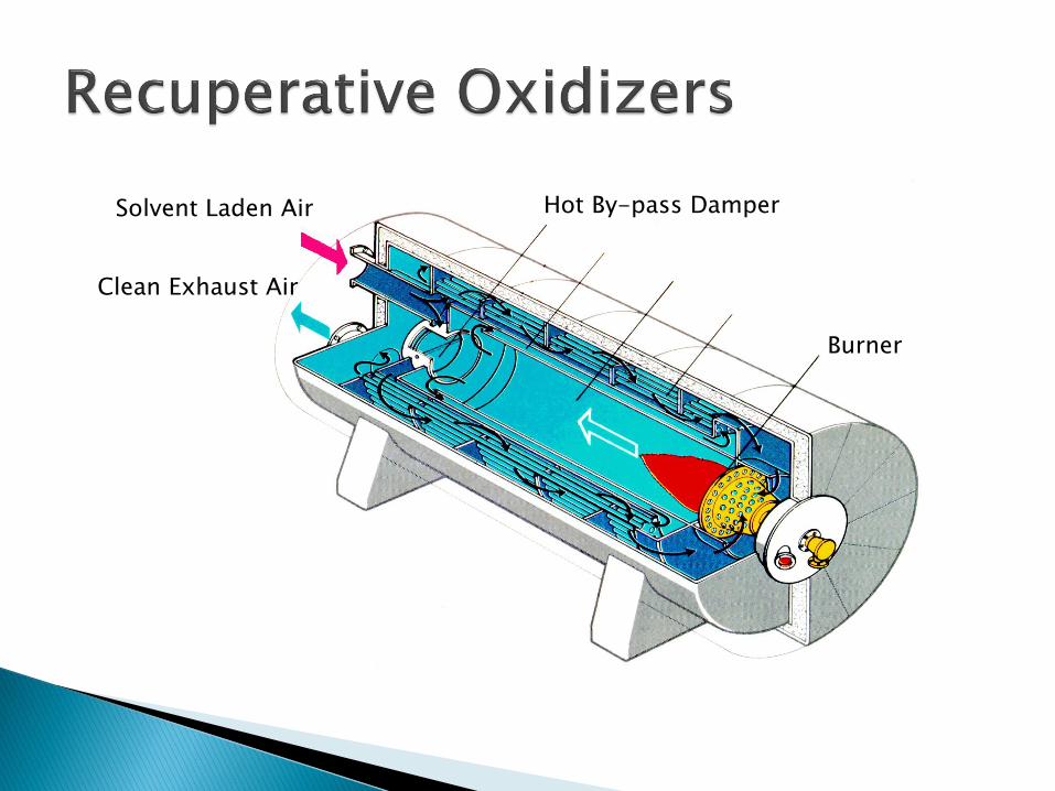
Hot By-pass Damper
Burner
Solvent Laden Air
Clean Exhaust Air
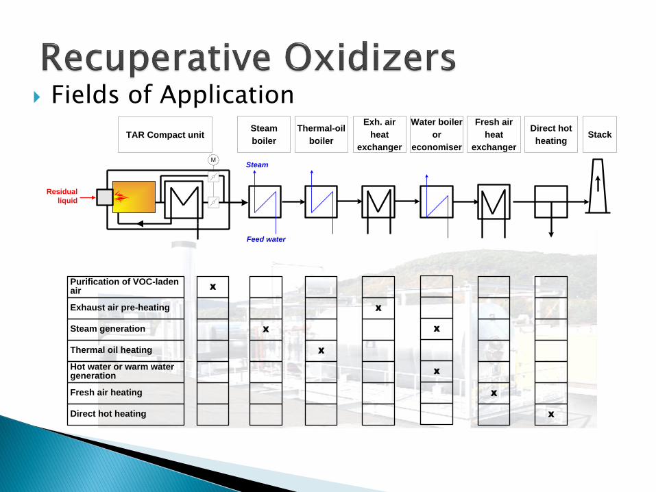
TAR Compact unit
Exh. air
heat
exchanger
Stack
Purification of VOC-laden air
Exhaust air pre-heating
Steam generation
Thermal oil heating
Hot water or warm water generation
Fresh air heating
Direct hot heating
M
X
X
X
X
X
X
X
X
Direct hot
heating
Fresh air
heat
exchanger
Water boiler
or
economiser
Steam
boiler
Thermal-oil
boiler
Steam
Feed water
Residual
liquid
Fields of Application
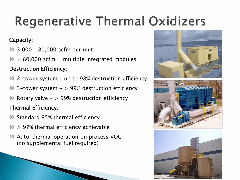
Capacity:
3,000 – 80,000 scfm per unit
> 80,000 scfm = multiple integrated modules
Destruction Efficiency:
2-tower system - up to 98% destruction efficiency
3-tower system - > 99% destruction efficiency
Rotary valve - > 99% destruction efficiency
Thermal Efficiency:
Standard 95% thermal efficiency
> 97% thermal efficiency achievable
Auto-thermal operation on process VOC (no supplemental fuel required)

Burner
Purge air
solvent-laden exhaust
air
Regenerative
heat exchanger
Purified
exhaust air

Fields of Application
Water
supply
X
XX
Pre-
Scrubber
Gas
injectionAerosol
seperator Pre-
heat
Liquid
Injection
RTO
Oxidizer
Bake
out
Heat
recovery Stack Scrubber
Gas
Waste water
Steam
Chemicals
X
Organic solvents
Halogenated compounds
Explosible gases
Ammonia, Sulfur, oils
or dustAerosols, droplets or
condensate
Organic dust
Liquids
Waste water
Chemicals
X
X X
X
X
X
X
X
X
X
X
X
X
X
X
X
X
X
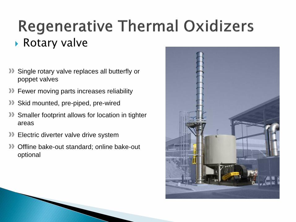
Rotary valve
Single rotary valve replaces all butterfly or
poppet valves
Fewer moving parts increases reliability
Skid mounted, pre-piped, pre-wired
Smaller footprint allows for location in tighter
areas
Electric diverter valve drive system
Offline bake-out standard; online bake-out
optional

Rotary valve
Twelve Chambers
5 Inlet, 5 Outlet, 1 Purge, 1 Idle
Operates as an odd tower standard unit
Single rotary valve indexes 30 degrees each 15
seconds to change flow path from inlet to purge
to outlet
Standard ≥ 99% destruction efficiency
≥ 95% thermal efficiency
Solvent loads up to nominal 25% LEL
No pressure fluctuations at the process
Exhaust in contact with Rotary Valve,
thus eliminating condensation
https://www.youtube.com/watch?v=G_8eqd3Fue8

Carbon or Zeolite ConcentratorsHigh gas volume, low VOC concentration process exhaust
is converted to low gas volume, high VOC concentration
for efficient VOC destruction in an oxidizer. Typical
conversion ratio is 10:1 (IE; 50,000 Scfm process
concentrated into 5,000 Scfm oxidizer)
Limited to ambient temperature process exhaust streams
up to 110ºF.
Solvents are adsorbed at ambient temperature onto the
adsorbent material and the purified air exits the unit
through the outlet plenum
Solvents are desorbed from the media in an isolated
plenum at elevated temperatures to liberate the VOC from
the media.
System efficiency; 96% - 98% concentrator removal
efficiency x 99% oxidizer destruction efficiency =
95% - 97% overall.

50,000 Scfm10 lbs/hr VOC
5,000 Scfm100 lbs/hr VOC

Fields of Application
Solvent-
Recovery
Solvent with
Dust < 3 mg/Nm³
Overspray 3-5 mg/Nm³
Overspray 5-10 mg/Nm³
Overspray > 10 mg/Nm³
Dust < 10 mg/Nm³
Dust + Aerosoles
Dust > 10 mg/Nm³
TAR
Compact
Unit
RTO
Oxidation
Unit
Ventury Dryfilter WESP
X
X
X
X
X
X
X
X
X
X
X
X
X
X
X
X
XX
X
X
X
X X
KPR System
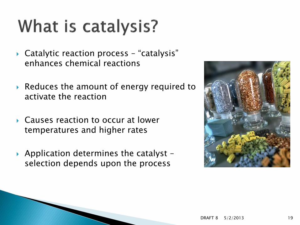
Catalytic reaction process – “catalysis” enhances chemical reactions
Reduces the amount of energy required to activate the reaction
Causes reaction to occur at lower temperatures and higher rates
Application determines the catalyst –selection depends upon the process
19DRAFT 8 5/2/2013

VOC’s
Products
CO2 & H2O
E
ΔH
E – Activation EnergyΔH – Heat of Combustion
E’
E’ – Activation Energy required with catalyst
ΔE – Change in Activation Energy

21
5/2/2013
Active sites for catalysis
Washcoat material provides high surface area Substrate
Active ingredient (e.g. precious or base metal) dispersed through a high surface area coating on a substrate, such as a ceramic block or a corrugated metal foil.
DRAFT 8

High surface area
Low pressure drop
Well suited for washing to extend useful life
Resistant to acid gas environments
Ceramic structure does not crush or create
fines
substrate
washcoatCeramic element Cross-section SEM
Installation – ceramic blocks

IPAMethanol
EthanolButanol
Toluene
MEK
Acetone
Ethyl acetatePropyl acetateIsobutyl acetate
Each VOC has its
own unique conversion curve

There are a wide range of applications for which catalysts are in use, including:
Power generation emissions◦ Natural gas turbines◦ Natural gas and diesel engines◦ Biomass boilers
Industrial waste gas emissions◦ Petrochemicals◦ Paint booths
Kitchen fume purification◦ Fast cook ovens, charbroilers
Aircraft cabin air purification

Various technologies reviewed at the start of VAM investigation in 2005
◦ Catalytic Thermal Oxidation not applicable as the methane concentrations and heat of
combustion result in temperatures above maximums allowed for existing catalysts
◦ Flares significant supplemental heat would be required resulting in
high operating cost
◦ Regenerative Thermal Oxidation Applicable to oxidize methane above 0.3% without using a
supplemental fuel source during normal operation
At methane concentrations above 0.4% excess heat is available
By now proven technology to reduce VAM emissions by 95% to 97%
25

Regenerative Thermal Oxidizer utilizes high mass, internal ceramic heat exchanger beds to hold heat
Bed #1 gives up heat to incoming VAM process air
Methane oxidation begins in the top of Bed #1 just prior to entering the oxidizer combustion chamber
Oxidation is completed in the oxidizer combustion chamber
26
1628 °F 1750 °F
70 °F142 °F
‣ Bed #2 pulls heat from the cleaned air exiting the combustion chamber‣ When the heat in bed #1 has been depleted and Bed #2 is fully charged,
airflow is reversed‣ Combustion chamber temperature operates at 1750F when self
sustaining at 0.3% methane

Excess heat available at methane concentrations above 0.4%
Oxidation of methane gives off more heat than required to maintain typical combustion chamber temperature of 1550F Combustion chamber temperature will begin to rise.
Evacuation of excess heat through a hot gas bypass -combustion chamber temperature to be stabilized at 1750F.
The evacuated hot air bypasses the outlet heat exchange bed and is transported directly to the stack – or to be used for…
27
0
10,000
20,000
30,000
40,000
50,000
0.20% 0.40% 0.60% 0.80% 1.00% 1.20% 1.40%
Hot
Byp
ass A
irfl
ow
scfm
VAM Exhaust Methane Concentration
VAM RTO System
VAM CH4 Concentration vs. Hot Bypass Airflow
Total RTO Airflow = 160,000 scfm at 70°F
Hot Bypass Flow
(Tcc = 1750F)
‣ Hot air or water in combination with a coil‣ Electricity generation in combination with a boiler and turbine or a ORC or a CPS

VAM Volume –160,000 scfm
VAM Methane Concentration –0.4% to 1.1%
Collection Point –16.4 ft x 16.4 ftcollection hoods
No CMM
3 RTO Oxidation System
No excess heat utilization – but theoretically possible
97% oxidation of methane
28
In operation since Summer 2012