ijeijournal.comijeijournal.com/papers/ijei september 2014/eee6 04042534... · web viewabstract:...
TRANSCRIPT

Power Quality & power control Improvement in DFIG Wind Turbine System using RSC& GSC Control system
1 Abhinav, 2 J Ranga1,2 EEE Department,SreeDattha Institute of Engineering & Science
Abstract: Grid side converter Doubly fed induction generators' control strategy is proposed. To improve the performance characteristics of DFIG under grid voltage fluctuation. The control strategy is implemented to satisfy grid codes like grid stability, fault ride , power quality improvement, grid synchronization and power control etc. Doubly-fed Induction Generator system uses back-to-back converters in the rotor circuits to meet the necessary needs. Doubly-fed Induction Generator is the most common rotator machine which is used on the grid connected wind energy conversion system for the fulfillment of the system requirement such as grid stability, fault ride through, power quality improvement, and grid synchronization and power control etc. So in order to improve the operation capacity of wind turbine under critical situation, the intensive study of both machine side converter control and grid side converter control is necessary. The machine uses two back-to-back converters. The grid side converter is modeled to control the active power and reactive power independently along with dc-link voltage. This scheme allows wind turbines to remain synchronized to the grid during faults or during voltage sags and swings. The proposed control strategy is confirmed with simulation results in MATLAB/SIMULINK
Keywords:, back to back converter.GSC and RSC Inverters Doubly Fed Induction Generators
I. INTRODUCTIONThe use of renewable energies attracts much attention, and
electricity generation from them is comparable to the conventional power plants. Wind energy is considered as one of the most promising infinite energy sources to produce electricity. So, a lot of extensive researches are done to use wind energy more effectively. Wind energy is the fastest growing source in the world for electricity generation. It is predicted that the installed capacity of wind farms around the world will reach to 17500 MW by 2012. Wind turbines are energy converters that can convert kinetic energy of wind into mechanical energy. There are two types of wind turbine used in wind farms: fixed speed and variable speed. Variable speed turbines are divided into two categories based on the generator used in them: Doubly-Fed Induction Generator (DFIG), and Permanent Magnet Synchronous Generator (PMSG). Each of these kinds of wind turbine systems has its own advantages
and disadvantages. Fixed speed wind turbines are directly connected to the grid. So, they are simple and cheap. However, the power system using Fixed Speed Induction Generators will face too many problems such as high reactive power absorption from the grid, and large fluctuations in output power. To fix these problems, wind turbine manufacturers tend to employ variable speed wind turbine generators which allow for independent control of active and reactive powers. These turbines produce 8-15% more energy output, as compared to fixed speed wind turbines. But, they need power electronic converters. So, it imposes economic burden on their cost. Grid connected wind turbines faces many problems. Low voltage ride-through, the grid voltage unbalance, and reactive power compensation are some of these issues. First concern which all kinds of wind turbines suffered from is disconnecting it from the grid during fault occurrence. This occurs since the voltage drops at the point of interconnection of the wind turbine. They will be disconnected from the network if the voltage drops to 10-20 percent of nominal voltage. This situation underlies an increase of the current in the stator and the rotor winding of the generator. Most induction generators are disconnected from the grid when such faults occur to avoid damage to the converter. Several ways are suggested to keep wind turbines connected to the
Fig.1.Double fed induction generator with grid connect system
Primary structure of DFIG wind turbine is Wind turbine is connected to DFIG through a mechanical shaft. Both rotor and stator is fed by the grid

network during voltage sag, such as utilizing SVC or STATCOM or other compensators. Low Voltage Ride through (L VRT) is one the most demanding requirements in network. The voltage requirement code which is suitable for the Nordic is shown it is known as Nordic. The grid voltage suddenly dropped to 25% due to a line fault, and then it increased with a slow buildup back to 1 pu. During this period, the wind generators must remain connected to the grid. During fault occurrence, the voltage at the point of interconnection of the wind turbine will decrease while the current will increase. So, high-fault currents could damage the generator stator and rotor windings. Thus, it is important to limit the fault currents. Several solutions have been offered to limit the fault current, such as Thyristor-controlled resistors have been considered as a mean to suppress short circuit currents. The required compensation voltage injection is suggested in this paper to limit the fault current.
According to the blade element theory, modeling of blade and shafts needs complicated and lengthy computations. Moreover, it also dependents on the detailed and accurate information about the rotor geometry. For that reason, considering only the transient events of the wind generator system, an equivalent lump mass modeling method of wind turbine system is normally used. In this method, the model of the drive-train system can be built consists of two masses, i.e. turbines mass and generator mass. The two masses are connected to each other with a shaft that has a certain stiffness and damping constant value. Fig.3 (a) shows the schematic diagrams of two-mass equivalent model of a wind turbine.
Fig.2. Low voltage ride
The other problem in wind power is unbalance voltage compensation. Overheating and torque pulsations occur following the grid voltage unbalance. As a result, wind farms will be disconnected from the grid beyond a certain amount of unbalance. In this paper the voltage unbalances is compensated by eliminating negative sequence voltage. The last issue considered in this study is reactive power compensation. Wind farms absorb high reactive power from the network. In FSIGs, this requirement is generally met by shunt capacitors. However, DFIGs can be operated at any power factor, depending on converter ratings. DFIG is considered as wind turbine generator. Rotor side converter use vector control for reactive power and speed control. The rest of the paper is organized as follows: Section II describes Dynamic Models of DFIG Wind Turbines. Section III expresses the Grid Requirements. Effects of Grid Faults on DFIG in Section IV and Simulation results are shown in Section V and the proposed scheme is compared with the conventional DFIG scheme. The paper is concluded in Section VI.
II MODELLING OF DFIG WIND TURBINES The main rotor structural components of a wind turbine,
namely blades, hub, low-speed shaft, gearbox, high-speed shafts and generator rotor. Modeling of a wind turbine drive train system is a complicated one.The equation of this model is given as:
(1)Where H is the inertia constant, T is torque and ω is angular speed. Subscripts g and w indicate the generator and turbine quantities, respectively. The shaft stiffness and damping constant value are represented in KS and Ds , ω0 is the base value of angular speed. All the quantities are in per unit value. DFIGs can be operated at any power factor, depending on converter ratings. DFIG is considered as wind turbine generator. Rotor side converter use vector control for reactive power and speed control. The rest of the paper is organized as follows: Section Wind turbine must stay connected even when the voltage at the point of common connection (PCC) with the grid drops to zero. The 150-ms delay Thus, voltage unbalance compensation can be achieved. The required voltage for injection should be divided by three to have the same role for each converter. The phase differences should be considered, as well. In the case of a single phase fault occurrence in the system, the converter in that phase can not participate for voltage unbalance compensation. So, this task should be divided between the other two converters.
In order to make a comparison of the transient stability grid-side and rotor-side DC currents, C is the DC-linkanalysis of the wind generator system with different capacitor.Equivalent models of the mechanical system, the traditional The voltage balance across the inductor is:One-mass shaft lumped model has been considered, whichare shown in Fig. 3(b). The equation of this model can begiven as:
(2)Where HM the inertia constant, DM is the damping
constant value of turbine. ωM is the angular speed of generator. Of cause, in this model the angular speed of turbine is equal to the angular speed of generator.
B. Control Strategy of Grid-side Converter A vector-control approach is used with a reference frame
oriented along the grid voltage vector position, enabling independent control of the active and reactive power flowing between the grid and the grid-side converter. The PWM voltage source converter is current regulated, with the d-axis current
Fig.5.Grid-side PWM voltage source converter arrangement to the grid
Fig.6. Vector-control structure for grid-side voltage source converter.
Used to regulate the DC-link voltage and the q-axis current used to regulate the reactive power. The schematic of the grid-side PWM voltage source converter, where ugabc are the three phase grid voltages, ugcabc are the three phase grid-side converter voltages, iga, igb, igc are the three phase grid-side converter currents, Rg and Lg are the inductor resistance and inductance, idcg, idcr are the
(3)By using the abc-to-dq transformation matrix, the
following equation can be given:
(4)Where ugd, ugq are the grid voltages in d- and q-axis, ugcd, ugcq are the grid-side converter voltages in d- and q-axis, igd, igq are the grid-side converter currents in d- and q-axis, ωe is the electrical angular velocity of the grid voltage
Neglecting harmonics due to the switching and the losses in the resistance and converter, the following equations can be obtained.
(5)Where m is the PWM modulation depth of the grid-side converter.
By using the control strategy described, it can be seen that the DC-link voltage can be controlled via igd. The currents igd and igq can be regulated by using ugcd and ugcq respectively. The control scheme thus utilizes current control loops for igd and igq, with the igd demand being derived from the DC-link voltage error. The igq demand determines the reactive power flow between the grid and the grid-side converter. Normally the igq reference value may be set to zero, which ensures zero reactive power exchange between the grid and the grid-side converter. The vector-control scheme for grid-side PWM voltage sourceconverter is shown in Fig.4, where u*gcabc are the reference values of the three phase grid-side converter voltages, u*gcd
,u*gcq are the reference values of the grid-side converter voltages in d- and q-axis, ig*d , ig*q are the reference values of the grid-side converter currents in d- and q-axis.
C. Rotor-side Converter Control Strategy A detailed model of DFIG which includes electro-
magnetic transients both in the stator and the rotor circuits is used when performing the transient stability studies. According to a standard per-unit notation, in a reference frame rotating at synchronous speed and taking the motor

convention, the transient models of grid-connected DFIGcan be represented by the detailed differential equations of the flux linkages:
(6)The equations of flux linkage is given as:
(7)Where ωs is the synchronous speed ;u, ψ, I, R, L are the voltage, flux linkage, current, resistance and inductance ; Lm is the inductance between rotor and stator subscript s、r indicate the stator and rotor of electric machine, respectively subscript d, q indicate the d, q components, respectively; s is slip ratio of DFIG.
The active and reactive power of stator can be given as:
Fig.7. Control structure of rotor-side’s active and reactive power decoupling Control.
(8)In order to implements the active and
reactive power decoupling control of DFIG, in this paper, we adopt stator voltage oriented rotor current control. It means that, usd=Us, usq=0.
The stator active and reactive power can be given as:
(9)The electromagnetic torque is given as:
(10)The vector-control scheme for rotor-
side PWM voltage source converter, where u*abcr are the reference values of the three phase rotor voltages, q* u*rd , ur are the reference values of the rotor voltages in d- and q-axis, q*i*rd , ir are the reference values of the rotor
currents in d- and q-axis. Stator active and reactive power can be controlled by regulating the d, q-axis components of rotor current.
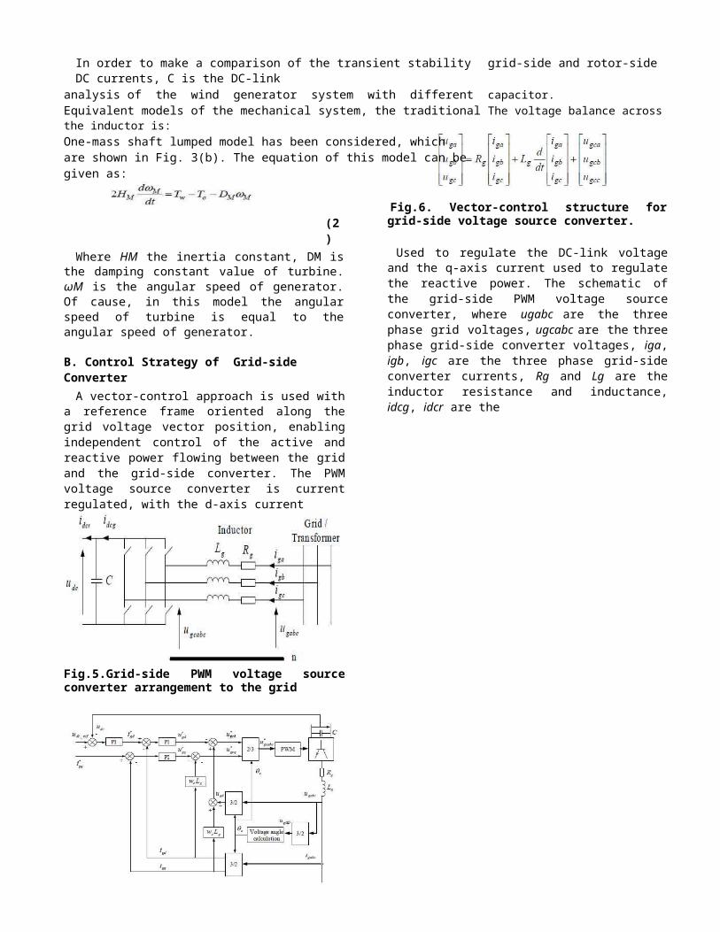
Fig.8. Schematic diagram of a grid connected DFIG wind turbine system.
III. POWER GRID SYSTEM
In the past wind turbines were separated from the grid following grid faults. However, as of now, separation of wind turbines for voltage values below 80% of the nominal voltage
would lead to loss of an undesirable portion of power generation. Therefore, utilities now require an FRT capability as specified in Fig. 8. Wind turbine must stay connected even when the voltage at the point of common connection (PCC) with the grid drops to zero. The 150-ms delay shown in the figure accounts for the normal operating time of protection relays. The red solid line in Fig. 1 marks the lower voltage boundary rather than any characteristic voltage behavior.
(11) Fig. 8. Fault-ride through requirements.

According to the short term interruption (STI) is allowed under specific circumstances. STI in area 3 requires resynchronization within 2 s and a power increase rate of at least 10% of the nominal power per second. In area 2 the interruption time allowed is much less, just a few hundred milliseconds. Besides, reactive power supply by wind turbines is a requirement during this period. According to the German grid code wind turbines have to provide a mandatory voltage support during voltage dips. The corresponding voltage control characteristics are summarized. Accordingly wind turbines have to supply at least 1.0 p.u. reactive current already when the voltage falls below 50%. A dead band of 10% is introduced to avoid undesirable control actions. However, for wind farms connected to the high voltage grid continuous voltage control without dead band is also under consideration.
.
IV FAULTS ON DFIGA. Configuration of DFIG based Wind Turbines
The rotor of the DFIG is equipped with three phase windings, which are supplied via the rotor side slip rings by a voltage source converter (VSC) of variable frequency and magnitude. Speed variability is ensured by the bi-directional transfer of slip power via the frequency converter. In the sub-synchronous operating mode (partial load range) the generator stator feeds all generated electrical power to the grid, and additionally makes slip power available which is fed from the frequency converter to the rotor. In the super-synchronous operating mode (nominal load range) on the other hand total power consists of the component from the generator stator plus slip power, which is fed from the rotor to the grid via the frequency converter. Active power, which is fed to the grid via the converter, amounts to roughly 25%of total power. The inverter rating is typically 25…30% of the total system power, while the speed range of the DFIG is +/- 30% around the synchronous speed. Lower inverter rating results in lower losses and thus higher overall efficiency, and lower costs for the inverter as well as for filters compared to a full-sized converter system. in the suggestedmethod all the tasks are shared between the three single-phase converters equally. Hence, the ratings of the converters can be decreased to some extent. Moreover, the scheme has many merits compared to conventional scheme. The conventional scheme has not the ability of a good compensation during fault occurrence. However, the proposed scheme offers an acceptable compensation for low-voltage ride-through purposes. Furthermore, the suggested method compensates the voltage unbalances more effectively. In the proposed design, controllability and feasibility is easier than the conventional scheme, as well.
Fig.11. DFIG based wind turbine Structure.
The control of the DFIG wind turbine embodies three parts: Speed control by controlling the electrical power reference provided to the converter as well as by the pitch angle. Rotor side converter (RSC) control directed at the control of active and reactive power on the stator side. Line side converter (LSC) control that keeps the Dc link voltage constant and provides the additional opportunity to supply reactive power into the grid. The RSC and LSC control is usually implemented together in the same converter control software whereas the speed/pitch control is realized as a separate unit. The converter enables decoupled active and reactive power control of the generator. Moreover, reactive power control can be implemented at lower cost since the DFIG system basically operates in a similar manner to that of a synchronous generator as the excitation energy is provided by the converter. The control of active and reactive power is accomplished by the fast-dynamic control of the magnitude as well as the phase angle of the EMF supplied to the rotor. The superior dynamic performance of the DFIG results from the frequency converter which typically operates with Sampling and switching frequencies of above 2 kHz.
B. Effect of Three Phase Grid Short CircuitsTo demonstrate the effect of a grid short-circuits a DFIG
based wind turbine together with a small grid has been simulated using a detailed time domain model. This example is aimed to show the effects of a short circuit without any countermeasures on the converter and generator side. The grid fault can lead to considerable over currents and over-voltages putting the whole facility under stress. Conclusions deduced from the simulation results are summarized. As a consequence of the sudden short circuit the stator currents contain DC-components. On the rotor side these currents appear as AC, superposing the much slower steady-state rotor currents injected by the converter. Thus the nominal rotor current is exceeded more than 2-3 times, which obviously is not acceptable.

considered that a single phase to ground fault happens in phase c at t=O.5s and it is cleared at t=O.7s, as it is shown. In this section, the scheme is compared with the conventional scheme. It is obvious that the proposed controller limited the fault current more effectively. So, the wind farms will remain connected to the grid during fault occurrence. The low voltage ride through fault will be achieved by this scheme. Fig. 9 and 10 shows the results for voltage unbalance compensation, i.e., unbalanced voltages and achieved balanced voltages for the new controller scheme. It is compared with the conventional scheme as shown. It is clear that the new controller scheme is more capable to compensate the voltage unbalances rather than the conventional scheme. It is also noted that the new controller scheme is responsible to maintain the DC link voltage. The DC link voltage with the new scheme and the conventional scheme is shown.
Fig.12. DFIG wind turbine during a three phase grid short circuit without FRT measures (theoretical case).
Higher rotor currents lead also to rising DC-link voltage. The DC-capacitor is usually not able to reduce this effect considerably so that the DC-voltage, without counter measures, would reach values of about 2-3 UDC_nominal, which are far away from capacitor specifications due to converter design. Due to the common control, the LSC tries to stabilize the DC-voltage. This causes the LSC current to increase up to 50% of the wind turbine nominal current, which represents a significant overload of the LSC. Despite the action of the LSC, the DC-voltage will reach values mentioned above. Immediately after the short circuit clearance, the wind turbine shaft will experience oscillating torque, the first peak of which reaching 2-3 to nominal leading to severe stressing of the turbine shaft. As a general conclusion one can easily realize that without countermeasures grid short circuits would easily result in deterioration of the converter system. On the other hand, fast separation from the grid is not a favorable option since utilities expect voltage support during the fault and in its aftermath. Besides, the active power in feed should not be interrupted for a longer period of time.
V. SIMULATION RESULTS
The simulations are performed using MATLAB/ SIMULINK software. It is assumed that a voltage unbalance occurs in the system in t= 1 s to t= 1.2s. It is also
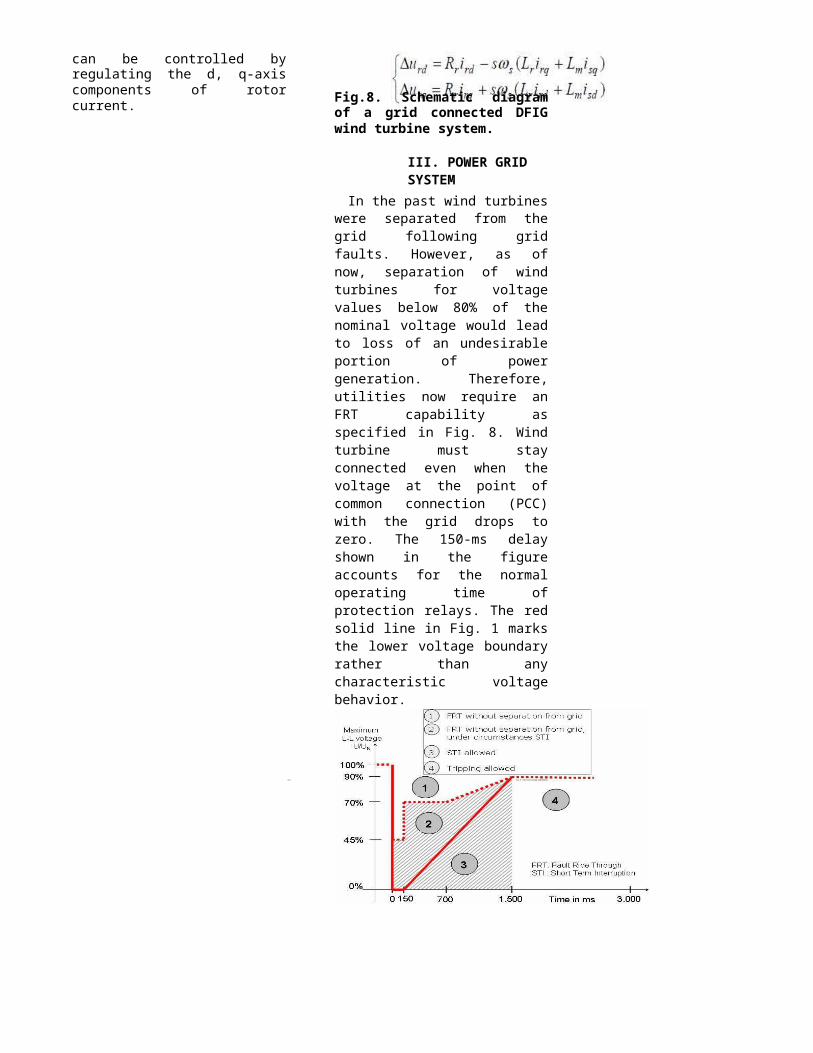
Figure13. Simulink diagram of proposed sstem
Figure14. DC- LINK Voltage.

Figure15. Three phase Voltages
Figure16. Torque Response of DFIG
Figure17. Active & Reactive Power at Stator.
It is seen that the new scheme can maintain the DC link voltage better than the conventional one.
VI. CONCLUSION In this DFIG wind turbines are connect to the electrical Network. Compared with conventional scheme, the proposed scheme not only has better ability of unbalanced voltage compensation during fault occurrence, but also has an ability to limit fault current. Moreover,in the proposed method controllability and feasibility is easier than the conventional scheme. In addition, with this scheme, it is possible to keep wind turbines synchronized to the grid. Besides, the ratings of the converters can be decreased to some extent, compared with the control method offered in the performance of the DFIG system is analyzed successfully.
VII. REFERENCES[I] K. Kook, K. McKenzie, Y. Liu et aI., "A study on application of energy stroage for the wind power operation in power system," in Power Engineering Society General Meeting, 2006.[2] W. Janssen, H. Luetze, A. Buecker, T. Hoffmann, and R. Hagedorn, "Low voltage ride through for wind turbine generators," U.S. Patent [3] D.," in Proc. 19th World Energy Congr., Sep. 2004. "Nordisk Regelsamling [4] (Nordic Grid Code)," Tech. Rep., Nordel Corp., 2004. 4J. Morren and S. W. H. de Haan, "Ridethrough of wind turbines with doubly-fed induction generator during a voltage dip," IEEE Trans. Energy Conversion.,