separation and sequestration co from flue gas with membranes
TRANSCRIPT

CO2 Separation and Sequestration
from Flue Gas with Membranes
Post-Combustion CO2 Capture Workshop Talloires, France
July 11, 2010
Richard Baker
Membrane Technology and Research, Inc.
Menlo Park, California, USA
www.mtrinc.com
� The nature of the problem
� Brief review of membrane gas separation technology
� Membrane-based CO2 capture from power generation
� Where we are now
� The future
2
Outline

1 billion metric tons CO2 = 1 gigaton CO2 > mass of all humans
AtmosphericCO2 concentration
(ppm)
CO2 emissions(billion metric tons)
Source: Oak Ridge National Laboratory, Carbon Dioxide Information Center
Year
Atmospheric CO2 Content is Increasing
3
> 40% of U.S. CO2 Emissions are
Produced During Electricity Generation
� Rules of thumb:Coal � powerOil � transportationNatural Gas � mixed
• 1,100 coal-fired power plants in the U.S.
• 5,000 coal-fired power plants worldwide
• Coal generates 60% more CO2 per MW compared to natural gas
Source:http://epa.gov/climatechange/emissions
4

Coal-Fired Power Plants are Large Point Sources
of CO2 Emissions
BoilerCoal
AirESP FGD
Ash
Steam to turbines
600 MWe plant emits ~10,000 tons CO2/day
• Gas is at atmospheric pressure, contains ~10-13% CO2 and is dirty: fly ash, SO2,Nox, and trace metals are present.
• Several CCS technologies are being considered (absorption, adsorption, membranes)
Sulfur
5
Natural Gas:
Petrochemicals: Hydrogen (Refinery): H2/CH4, CO, CO2Propylene/Nitrogen
CO2/CH4, CH4/N2
NGL/CH4
Membrane Technology and Research
MTR designs, manufactures, and sells membrane systems for industrial gas separations
Customers include: BP, Chevron, Dominion Exploration, Ercros, ExxonMobil, Formosa Plastics, Innovene, Sabic, Sasol, Sinopec, Solvay, and Statoil.
6
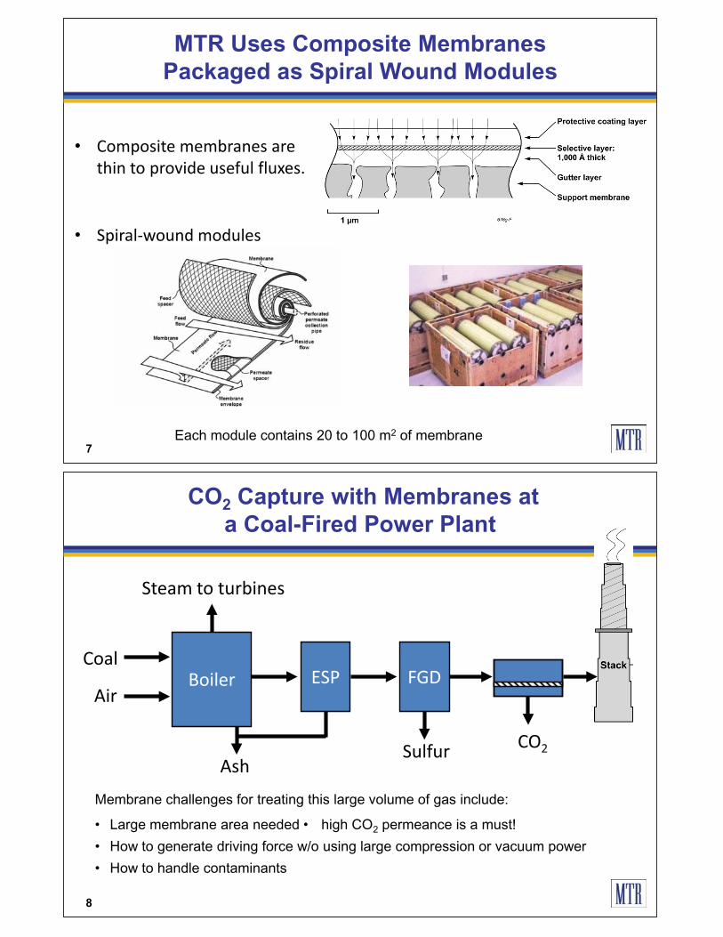
• Composite membranes are thin to provide useful fluxes.
MTR Uses Composite Membranes
Packaged as Spiral Wound Modules
Each module contains 20 to 100 m2 of membrane7
• Spiral-wound modules
CO2 Capture with Membranes at
a Coal-Fired Power Plant
BoilerCoal
CO2
AirESP FGD
Ash
Steam to turbines
Membrane challenges for treating this large volume of gas include:
• Large membrane area needed • high CO2 permeance is a must!
• How to generate driving force w/o using large compression or vacuum power
• How to handle contaminants
Sulfur
8

• Compressor electricity cost is significantly more than the annualized module replacement cost.
• A two megawatt (2,000 kW) compressor costs $1,000,000 and uses $1,200,000 electricity/y
Membrane plant design as drawn by a plant purchaser
Lessons from the Current Industry
9
10
Vacuum operation uses• Ten times the membrane area• Only 40% of the compression power
Pressure ratio = 10, � = 50, P/�������������� �������������90% CO2 recovery
Compression or Vacuum Operation

Preliminary Conclusions
• Power consumption is the key issue
• The maximum affordable pressure ratio is about 10
• A single-stage process is not going to work
• Vacuum operation is likely the lowest energy design
• Membrane areas will be big � millions of square meters
• A selectivity of 30 to 50 seems optimum
11
• Countercurrent sweep with combustion air provides “free” driving force � lower energy required.
• CO2 recycled in the combustion air stream decreases membrane area required.
• Water in the flue gas helps
The MTR Process
12

Membrane Assisted CO2 Liquefaction and Injection
13
The Total MTR Process –
The Lowest Energy Case
14

15
10
12
14
16
18
20
22
0 1 2 3 4 5 6
90% capture
Fra
cti
on
of
pla
nt
en
erg
y n
eed
ed
(%
)
Membrane area (MM m2)
1.1 bar
1.5 bar
2.0 bar
2.5 bar
3.0 bar
Lowest
cost
case
(a)
Lowest
energy
case
15
20
25
30
35
40
0 1 2 3 4 5 6
90% capture
Ca
ptu
re c
ost
($/t
on
CO
2)
Membrane area (MM m2)
3.0 bar
1.5 bar
2.0 bar2.5 bar
1.1 bar
(b)
Lowest
cost
case
Lowest
energy
case
But millions square meters of membranes are required
Predicted Process Costs Look Attractive
� Total energy use in plant is 56 MW; uses 5.5 MW water pumps
� Plant produces 100 million m3/yr of fresh water
Membrane Plants
of The Required Size Exist Today
Ashkelon desalination plant
� 40,000 spiral-wound RO membrane modules (Dow Filmtec®)
� 1.5 million m2 membrane area
16

Polaris™ Membranes are
Extremely Permeable to CO2
10
20
30
40
50
60
100 1,000 10,000
CO2/N2
selectivity
CO2 permeance (gpu)
PolarisTM
Target area
identified from
design calculations
Commercial
natural gas
membranes
Polaris™ membranes are 10 times more permeable to CO2 than conventional membranes used for natural gas treatment; Pure-gas data at 25 C and 50 psig feed pressure 17
Higher CO2 Permeance Reduces Cost
More Than Higher Selectivity
0
10
20
30
40
50
0 20 40 60 80 100
Capture cost
($/ton CO2)
Membrane CO2/N2 selectivity
2,000 gpu
1,000 gpu
4,000 gpu
90% CO2 capture
Pressure ratio = 5.5
Polaris 1 CO2 permeance
Polaris 3
Baseline amine capture cost is >$80/ton CO218

Where We Are Now
APS Red Hawk Power PlantField Test
19
Red Hawk Module Test Unit
MTR is conducting field demonstrations at Arizona Public Service (APS) power plants
Algae Reactors
Red Hawk is a 1060 MWe natural gas-fired power plant located near Phoenix, Arizona
CO2 from Red Hawk plant is sent to algae reactors for biofuel production
20

APS Cholla Power Plant Feasibility Test
� Six-month test with coal-fired flue gas started in April 2010
� Polaris™ membrane system captures 1 ton CO2/day
21
Planned Future Development
Cholla II skid (20 ton CO2/day or 1 MWe) is proposed to begin operation in late 2011
22

23
High Permeance Membranes in
Low Cost Membrane Modules and Housings are Key
0
10
20
30
40
50
60
70
80
0 1,000 2,000 3,000 4,000
CO2/N
2selectivity
CO2 permeance (gpu)
Feed = 50 psig and 25°C
2006
baseline
Red Hawk
2008
Cholla I
2009
Cholla II
developmental
membranes
Membranes are getting better
DOE Post-Combustion CO2 Capture Timeline
Cholla I (1 ton CO2/day)�Collaboration with APS and EPRI�Demo module performance at Cholla test site
Large Scale Field Testing (100-500 ton/day)
�Utility site
24
2014 2016 2018
Large-Scale Field Testing
5– 25 MWe
Now
Cholla II Demo (20 tons CO2/day)•Babcock and Wilcox will evaluate CO2 recycle idea �EPRI will investigate flue gas water recovery

Thank You