sensor enabled scientific monitoring and reliable ... · scientific monitoring and reliable...
TRANSCRIPT

SensorEnabledScientificMonitoringAndReliableTelecommunications(SMART)Cable
Systems:WetDemonstratorProjectDescription
JTFEngineeringTeam
WhitePaper
Issue1.0July2016

DOCUMENTCONTROLSHEETForRevisionsandProposedChangesContact:
Stephen [email protected]
+1-703-821-3145Issue Date Status/Reason0.1 9June2016 FirstDraftforEngineeringteamreview0.2 13June2016 Reviseddraft0.3 8July2016 Draftincorporatingengineeringteaminput1.0 11July2016 Documentreleased.

TABLEOFCONTENTS1 Introduction...................................................................................................................................52 References.......................................................................................................................................63 Purpose............................................................................................................................................64 Background....................................................................................................................................65 Scope.................................................................................................................................................76 DemonstrationSystem Development...................................................................................77 Assumptions...................................................................................................................................88 SystemDescription......................................................................................................................98.1 Overview..........................................................................................................................................98.2 HostingObservatory.......................................................................................................................108.3 OptionalHostingLocations............................................................................................................108.4 SeabedPlacement..........................................................................................................................118.5 CablePlantandRepeaterHousings...............................................................................................118.6 CableTerminationAssembly..........................................................................................................128.7 RepeaterHousing...........................................................................................................................138.8 SensorsandSensorElectronics......................................................................................................148.9 SensorAttachment.........................................................................................................................148.10 Communications............................................................................................................................158.11 BandwidthEstimate.......................................................................................................................168.12 PowerFeed.....................................................................................................................................178.13 RepeaterHousingMechanicalandThermalConsiderations.........................................................218.14 DataManagement..........................................................................................................................228.15 Spares.............................................................................................................................................22
9 ProjectDescription...................................................................................................................229.1 Owner.............................................................................................................................................229.2 HostObservatoryorSystem...........................................................................................................229.3 ProjectManagement......................................................................................................................239.4 DesignAuthority.............................................................................................................................239.5 HealthSafetyandEnvironment......................................................................................................239.6 QualityAssurance...........................................................................................................................239.7 Permitting.......................................................................................................................................239.8 SiteSelectionandMarineSurvey...................................................................................................239.9 ProvisionofCable,RepeaterHousings,andSystemAssembly......................................................249.10 CableTerminationAssembly..........................................................................................................249.11 ProcurementofOff-the-ShelfItems...............................................................................................259.12 ProvisionofIntegratedSensorPackageandCabling......................................................................259.13 AttachmentHardwareDesignandManufacture...........................................................................259.14 PowerSystemDevelopment..........................................................................................................259.15 CommunicationsSystemDesign....................................................................................................259.16 MechanicalandThermalDesign....................................................................................................259.17 InitialBenchTests...........................................................................................................................26

9.18 PreliminaryIntegration..................................................................................................................269.19 CablePlantIntegration...................................................................................................................269.20 Installation......................................................................................................................................269.21 Commissioning...............................................................................................................................279.22 DataManagement..........................................................................................................................279.23 Summary........................................................................................................................................27
10 OperationsandEvaluation.................................................................................................2911 PlanofWork...........................................................................................................................2912 Budget........................................................................................................................................29
LISTOFFIGURESFigure1:OverviewofWetDemonstrator.................................................................................................10Figure2:SeabedPlacement.....................................................................................................................11Figure3:CTAFunctionalBlockDiagram....................................................................................................13Figure4:RepeaterHousingFunctionalBlockDiagram.............................................................................13Figure5:OptionsforExternalSensorPods...............................................................................................14Figure6:SensorAttachment.....................................................................................................................15Figure7:CommunicationsOverview........................................................................................................16Figure8:OverviewofPowerFeeding.......................................................................................................18Figure9:DC-DCIsolation...........................................................................................................................19Figure10:ExampleCurrentSourceCircuits..............................................................................................19
LISTOFTABLESTable1:EstimatedBandwidthUtilizationperSensorSet.........................................................................17Table2:ExampleLineCurrentCalculation................................................................................................20Table3:ExampleVoltageDropCalculation..............................................................................................21Table4:SummaryofProjectActivities......................................................................................................28

1 IntroductionTheuseofsubmarinetelecommunicationscablesystemsforenvironmentalmonitoringanddisasterwarninghasreceivedsignificantattentionsincefirstproposedoverfiveyearsago.The International Telecommunication Union (ITU), the Intergovernmental OceanographicCommission of the United Nations Educational, Scientific and Cultural Organization(UNESCO/IOC),andtheWorldMeteorologicalOrganization(WMO)establishedtheJointTaskForce(JTF)inlate2012toaddressthetechnical,commercialandlegalaspectsofaddingthiscapabilitytocommercialtelecommunicationscablesystems.Effortstodefineanddevelopsuitablemethodsof integrating temperature,pressure,andacceleration sensors into suchcablesystemshavebeenongoingduringthattime,buthavenotprogressedbeyondhighlevelrequirementsandconceptualdesigns.
Manyentitiesareintriguedbytheconceptofasensorenabledcablesystem; however, thebusiness case or owner encouragement to introduce long termmonitoring capability intocommercial cable systems has not yet occurred. It has thus become clear that furtherdevelopment of sensor enabled Scientific Monitoring And Reliable Telecommunications(SMART) cable systems requires additional political, financial, andscientific commitments.Obtaining such commitments in turn require a demonstration of the effectiveness andpracticalityoftheproposedapproach.Theconceptofa“WetDemonstrator”systemsuitablefordeploymentandmediumtermoperationhasbeenputforthasafirstcriticalsteptowardsindustryacceptance.
This paper presents a new approach to development of the Wet Demonstrator. Thebackgroundandrationaleforpursingthisnewapproacharedescribed.Theprojectscopeandmajor assumptions are defined. The project is presented in twomajor sections: first thesystemdesignispresentedinSection8,thentheprojectactivitiesaredescribedinSection9.Finally,operationsanddatavalidationarediscussed.

2 ReferencesThereadersofthispaperareassumedbefamiliarwiththefollowingmaterial:
1. JointTaskForceHomePage
http://www.itu.int/en/ITU-T/climatechange/task-force-sc/Pages/default.aspx
2. OverviewPresentation
http://www.itu.int/en/ITU-T/climatechange/task-force-sc/Documents/Sensing_the_Oceans.pdf
3. ITU-WMO-UNESCOIOCJointTaskForceFrequentlyAskedQuestions
http://www.itu.int/en/ITU-T/climatechange/task-force-sc/Documents/JTF_FAQs.pdf
4. GeneralrequirementsofaSMARTcable
JTFEngineeringWhitePaperdated13June2016.
5. 5thWorkshopon"SMARTCableSystems:LatestDevelopmentsandDesigningtheWetDemonstratorProject",Dubai,UnitedArabEmirates,17-18April2016.
http://www.itu.int/en/ITU-T/Workshops-and-Seminars/5-ws-smart-cable-systems/Pages/Programme.aspx
3 PurposeThispaperservesseveralpurposes.FirstistodocumentaconsensusamongthemembersoftheJTFEngineeringcommitteeregardingapossibleapproach.SecondistoallowassessmentoftheproposedapproachbyinterestedpartiesoutsidetheJTF.Thirdistopermitpotentialproject participants, including suppliers, integrators, observatory operators, and marineinstallers, toevaluate theirpotential role in theproposed systemdevelopment. Potentialparticipants are asked to indicate their level of interest and capabilities in a Request forInformation (RFI) to be issued by the JTF during the third quarter of 2016. Finally, theproposedsystemdesigncombinedwiththeRFIreplieswillprovideabasisforproposalstofundingagencies.
4 BackgroundFunctionalrequirementsforthewetdemonstratorhavebeendevelopedanddocumented,with theexpectation thatoneormore suppliers, funding source(s),orbeneficialowner(s)wouldstepforwardtoleadthedevelopmentanddeployment.Thefunctionalrequirementsarenotdescriptive; implementation details are intentionally left to the discretion of theproject developer or their chosen supplier. Development of aworking system from thefunctional requirements requires a project team with experience in both submarinetelecommunications systems and ocean observing systems. The project is within thecapabilitiesofmostofthecommercialcablesystemsuppliers,however,thesupplierstothe

commercialtelecommarkethavebeenunabletojustifydevelopmentofnewcapabilitiesforwhichthemarketdemandandbusinessmodelareunproven.
Compounding this difficulty are concerns regarding the commercial and legal aspects ofsensorenabledcables,whichhaveresultedinreluctanceamongpotentialownersofsuchasystem to include this new technologywithout extensive qualification efforts and carefulconsiderationoftheinternationallegalframeworkforscientificresearchintheoceans.Publicsectorfundingformediumtolargeprojectsisconstrained.Inspiteoftheworkdonetodate,effortstoengagefundingsources,potentialcableowners,andpotentialsuppliershavenotyetreacheda‘proofofconcept’stage.
5 ScopeThis document presents an implementation plan for a demonstration project. Thisdemonstrationisintentionallylimitedtoscientificfunctions.Demonstrationofthecapabilitytodeploysensorsusingunmodifiedcable layingmethodsisthekeyobjective. Theprojectincludes the mechanical integration of sensors with housings and cable which arerepresentativeofacommercial telecomscable. Inparticular, repeaterhousingsandcablewhichareidenticaltothoseusedinacommercialtelecomsystemmustbeused.Cablelayingmethods must likewise be identical to those used for commercial telecommunicationssystems,withtheexceptionthatthehookuptoanexistingoceanobservatorymayemployappropriatemethods.Integrationofpoweringandcommunicationsfunctionswithatelecomsystemwillnotbeundertaken;insteadoff-the-shelfcommunicationscomponentsandsimplecustompowersupplieswillbeemployed.Theseitemswillbeinternaltothehousingsandwillnot impacttheabilitytodeployorrecoverthesystem. Existingsensordesignsandsensorelectronicswillbeused.
Thesystemdesignandprojectplanoutlinedhererepresentaninitialproposal intendedtoillustrateonepossibleapproach.Alternativemethodswhichimprovetheresults,reducecost,improvedeliverytimes,orreducerisksmayalsobeconsidered.
6 DemonstrationSystem DevelopmentAmodified approach to thedevelopmentof a SMART cablewet demonstration system isproposed.Thisapproachisbasedonthemethodsusedoverthelastdecadetodevelopcabledoceanographic observatories. The successes (and occasional setbacks) encountered inconstructingandoperatingtheseobservatorysystemsprovideausefulframeworkonwhichtobuild.Manyoftheelementsnecessarytoconstructthewetdemonstratorhavealreadybeen proven, including Ethernet based communications systems, cable terminationassemblies,thesensorsthemselves,andon-shoredatamanagementandpoweringsystems.
Intheproposedapproach,supplierswillbeengagedprimarilytodeliverandintegrateexistingproducts. Off-the-shelf components are used to the greatest extent possible. Somedevelopmentworkwillbeneeded,principallyformechanicalitemsandthepowersupplies,butthese can be addressed by existing low-cost, commercial technology. Where new

developmentisrequired,specialistswillbeengagedtoaddressfocusedtasks.Thedetailed(and costly) development and qualification work necessary to support integration into afunctioningcommercialcableisdeferreduntilafterdemonstrationissuccessfullycompleted.
This modified approach simplifies the scope of work of each potential supplier. Mostimportantly,thescopeforthecablesupplierislimitedtothesupplyandintegrationofcableandemptyrepeaterhousings.Withtheremovalofanydevelopmenteffort,itisanticipatedthatoneormorecablesystemsupplierscouldsupporttheproject.
Thismodifiedapproachcomeswithonecaveat:nosingleentitywillbesolelyresponsiblefortheoverallperformanceof theproject. Theusual industryapproach is toengageaprimecontractor,whooverseestheprojectschedule,securesallresourcesnecessarytocompletetheproject,managesallprojectcosts,andisfullyresponsiblefortechnicalperformance.Oneoftheimpedimentstodevelopmentofthewetdemonstratoristhat,todate,noentityhasbeen willing to take on this responsibility. Under the proposed approach, functionalperformance must be managed collaboratively through design reviews and integrationtesting.Thismirrorstheapproachusedoncabledobservatorysystemsand,whenproperlyimplemented,hasbeenshowntobeeffective.Riskofcostoverrunswillbemanagedthroughtheuseofclearlydefinedworkscopes,designreviews,carefullymanagedintegrationactivitiesand,whereverpossible,competitiveprocurement.
Anoverallprojectmanagerisenvisioned,buttherolewillbestrictlythatofdirectingprojectactivitiesandfacilitatingcommunication;theprojectmanagemententitywillnotbeaskedtoabsorbunforeseencosts. Given the structureof theproposedproject, it is likely,butnotnecessary,thattheoperatorofanexistingobservatorycanactastheprojectmanager.
Itisassumedthatthewetdemonstratorwillbehostedonanexistingobservatory,althoughthis isnota strict requirement. Theuseofanexistingobservatoryprovidesa convenientconnectionpointindeepwater,avoidingthecostofprovingandinstallinganarmoredshoreendcable.Permittingissueswouldalsobeminimized,againbyavoidingthenearshorearea.Existingobservatoriesalsohaveextensivedatamanagementcapabilitieswhichcanbeappliedtosupportthewetdemonstratorproject.
Thedesiredresultoftheproposedapproachistofocusthewetdemonstratorprojectonthekeyobjectiveofprovingthatsensorscanbedeployedusingstandardindustrypracticesforcableandrepeaterinstallation.
7 AssumptionsThebasicdesignassumptionsforthewetdemonstratorprojectare:
6. Thedesignadherestotheperformancerequirementsandguidingprinciplessetforthin General requirements for sensor-enabled submarine cable systems JTFEngineeringWhitePaperdated13June2016.
7. Thewetdemonstratorincorporatesaminimumofthreesetsofsensors.Threesensorsetsdemonstraterepeatabilityandcanbedistributedspatiallysuchthatthedirection

oftsunamiscanbedetected.
8. Thewetdemonstratordesignpermitsadditionalsensorsetsiffundingallows.
9. Thewetdemonstrator isdesigned toconnect toacabledobservatory scienceportproviding 100BASE-T Ethernet and 375-400VDC power. Connection to an out-of-serviceshoreendortoabranchofanewcommercialcableisalsopossible.
10. Thewetdemonstratoristobeinstalledinwaterdepthsbetween1,000and3,000m.
11. Thewetdemonstratorisinstalledoutsidetheterritoriallimit(12nm)ofanycountry.Operational permits are the responsibility of vessel operators. Cable crossings, ifnecessary, are to be performed according to the International Cable ProtectionCommittee(ICPC)RecommendationNo.2.Othertypesofcrossingsshouldbeavoided.
12. Thewetdemonstratorhasanexpectedservicelifeofthreetofiveyears.Thisshallbeshownthroughreliabilityanalyses.
13. Nocommercialtelecommunicationsfunctionsareincorporated.
8 SystemDescriptionThis section provides a general description of the wet demonstrator design. The designconceptsandspecificexamplesarenotintendedasafinaldesign,butrathertoshowthatthewetdemonstratorisafeasibleandrealisticproject.
8.1 Overview
Thewetdemonstratorsystemdesignincludesthreeormoresensorsetsconnectedtoatrunkcable spaced up to 50km apart. Each sensor set consists of one pressure sensor, onetemperaturesensor,andathreeaxisaccelerometer.Acommunicationssub-systemensuringthedatacommunicationsbetweensensorsetsandan interface to thehostobservatory ishoused in a telecommunications repeater housing, alongwith the power supplies for thecommunicationssub-systemandtheassociatedsensorset. Thepressureandtemperaturesensors are placed in a pod 5-25 meters from the repeater housing; this separation isnecessarytoensurethesensorsarecoupledtotheenvironmentandtoisolatethesensorsfrom local temperature affects caused by electronics in the repeater housing. Theaccelerometers may be placed in the repeater housing or in the sensor pod; the mostappropriatelocationmaybedeterminedduringdetaileddesign.Aninterfacepodconnectsthewetdemonstratortothehostingobservatory.TheseelementsandtheirrelationshipsareshowninFigure1.Thehostobservatorydeliverspowerandcommunicationsfromashorestationtotheinterfacepointdenotedbythewetmateconnector.Thefinalelementofthewetdemonstratoristhedatamanagementandarchivingfacility,whichisnotshownhere.

Figure1:OverviewofWetDemonstrator
8.2 HostingObservatory
Thehostingobservatoryisrequiredtoprovidebothphysicalinfrastructureandoperationalservicestothewetdemonstratorinamannersimilaroridenticaltothatusedtosupportmanyother connected instruments and sensors. The primary connection point to the WetDemonstrator is a wet-mate connector providing 375-400V DC power and an electricalEthernetcommunicationinterface;inobservatoryparlance,thisistermeda“scienceport.”Thepowerrequirementmayrangefromtenstoseveralhundredwatts(asubstantialportionofwhichisdissipatedasresistivelossesinthecableorlosttoinefficienciesinthepowersupplyelectronics).Electrical,100Mb/sEthernetprovidessufficientbandwidthandavoidsthecostofopticalwet-mateconnectors.Pulsepersecond/precisetimingisnotrequiredforthewetdemonstrator(althoughthismaybearequirementforafullyrealizedSMARTcablesystem).Theserequirementscanbesupportedbyseveralexistingobservatories.
Aside from thebasic servicesofpowerandcommunications, thehostingobservatoryalsoshould provide data management, support any permitting requirements, and assist withinstallationlogistics.Awrittenscopeofworkforthehostingobservatoryisanecessaryaspectoftheoverallprojectdevelopment.
8.3 OptionalHostingLocations
Thewetdemonstratormayalsobeconnectedtoanout-of-serviceshoreendorabranchfromanewcablesystem.Inthefirstcase,theout-of-servicecableiscutandthewetdemonstratorjointeddirectlytotheexistingcable.Inthecasewherethewetdemonstratorisconnectedtoanewcablesystem,thesectionfromtheshore-endtothewetdemonstratorwouldconsistof dual conductor cable, which provides an independent power feed path for the wetdemonstrator. Anadditional fiberpairtosupportcommunicationstothewetdemonstratorwouldalsobeprovided in this section, togetherwithanappropriatebranchingunit. Dualconductorcablehasbeenusedonsomespecialpurposesystemsbutisnotgenerallyavailableinthemarketplace.Inbothcases,aconstantcurrentpowerfeedandasmallsetofnetworkingequipmentarelocatedinthecablelandingstationtosupportthewetdemonstrator.
Interface Pod / Cable Termination Assembly
Repeater Housing
Wet-mate connector
Lead-in cable (if required)
Ground rope and anchors
6-50km
6-50km
50-100m
6-50km
End cable and seal
Repeater Housing
Repeater Housing
Sensor Pod
Sensor Pod Sensor Pod
Hosting Observatory

8.4 SeabedPlacement
Thewetdemonstratorshouldbeinstalledinalocationthatpermitssurfacelayingofallcable.(Plowburialofsensorsisnottobedemonstratedinthisfirstdemonstratorprojectandwillnotberequired.)Ataminimum,bathymetricsurveydataareneeded.Ifthisisnotavailable,a seabed survey must be conducted prior to cable laying. During the lay operation, anappropriatecatenarymodellingtoolwillbeusedtoplanandcontrolthelayingoperationandtoestimatethetouchdownlocationofthesensorpackages.TheestimatedlocationmaylaterbecomparedtotheactuallocationasdeterminedbyROVoracousticsurvey.
Thewetdemonstratorisnotionallyalinearsystem,howeverthatdoesnotimplythesensorsmust be laid in a straight line. By laying thewet demonstrator in an “S” or shallow “U”configuration,oneofthesensorsetscanbeplacedoutoflinewiththeothertwo;thisissothedirectionofpropagationoftsunamis,forexample,canbemoreaccuratelydetermined.
Acableshipcannotmakesharpturnsandmaintaincontroloverplacementofthecable.Theremustbesufficientcablelengthtoallowgradualturnsawayfromonerepeaterlocationandtowards thenext. Forexample,aseriesof15degreecoursealternationscanbemadetoachievetheconfigurationshowninFigure2:SeabedPlacement.Inthisexample,thesensorsare separated by 50km of cable, the X and Y offsets are approximately 45km and 15kmrespectively.Altercoursesare7kmapart.Thisplacementmethodcouldalsobeusedtotesttheaccuracyofestimatedrepeaterpositionsontheseabed.
Figure2:SeabedPlacement
8.5 CablePlantandRepeaterHousings
Thewetdemonstratorincorporatesseveralelementsfromcommercialtelecommunicationssystems,inparticularthecableandrepeaterhousings.Inaddition,seaelectrodestoprovideapowerreturnpathareneededandmaybeadaptedfromthoseusedincommercialtelecomsystems.Acableterminationassembly(CTA)isrequiredtointerfacethetelecomcabletothehostingobservatory.
Therepeaterhousingsmustaccuratelyrepresentthesuppliers’standardproduct.Notethatthepowercircuitsandopticalamplifiersusedinatelecomsystemarenotneededforthewetdemonstrator. Instead,bespokepowerelectronicsandoff-the-shelfEthernetswitchesare
45km
15km
7km
Sensor Location 1
Sensor Location 3
Sensor Location 2
45km
CTA Cable end15º Alter Courses

used.Fiberopticandpowerconnectorsentertherepeaterhousinginthesamemannerasinatelecommunicationssystem.Oneadditionalpenetrationisrequiredforsensorconnections;this will be a straight bore suitable for a commercially available penetrator / connectorcombination.
Thecablelikewisemustbeastandardproduct.17mmcableisassumed,although21mmmaybeusedifavailable.11mmor14mmcablesarenotgenerallyusedforrepeateredsystemsandarenotconsideredhere.Aminimumofonefiberpairisneeded,althoughacablewith2or3fiberpairswouldprovidegreaterutilityforfuturereuse.Centerconductorresistanceisassumedtonominallybe≤1.6Ω/km.Theexpectationisthatnoarmoringorextraprotectionisrequired.
AttheCTA,aseaelectrodeprovidesapowerreturnpath.Thecathode(+)endislocatedneartheCTA.AMixedMetalOxide(MMO)electrodeisrequiredandmaybeofthesametypeusedwithcommercialbranchingunits.Atthefarendofthecable,anotherelectrodeprovidesapathtoseawater;theanode(-)endmaybeanMMOelectrode,platinumstrip,orarmorwireconnection.
8.6 CableTerminationAssembly
TheCTAprovidesatransitionfromthebackbonecabletoaflyingleadwhichisconnectedtothehostingobservatory.VarioustypesofCTAshavebeendeployedinconjunctionwithbothobservatoryandoil&gasprojects. Forthewetdemonstrator,theCTAisrequiredtohousepower and communications electronics. A design based on a repeater housingwould besuitable,butthisdoesnotprecludeotherapproaches.
TheinternalfunctionsoftheCTAareshowninFigure3.Thepowercircuitsisolatethewetdemonstratorfromtheobservatorypowersupply;thisisnecessarysothattheobservatorypowersupplyisnotconnectedtotheseawaterreturn,aconditionthatwouldbeinterpretedasafault.Thecurrentsourceprovidespowerfeedtotherepeaterhousingsinamannerverysimilartothatusedincommercialtelecomcables.AnEthernetswitchisusedprimarilyforelectrical/opticalconversionbutcanalsoacceptdatafrommonitorcircuitsorlocalsensors.Furtherdetailsofthepowerandcommunicationsfunctionsarediscussedin latersections.Note that theCTAcouldsupportasetofsensors if there is sufficient internalvolumeandspaceforacablepenetrator.

Figure3:CTAFunctionalBlockDiagram
8.7 RepeaterHousing
The purpose of the repeater housing is to provide an actual telecommunications systemrepeater body to house the power and communications functions required for thedemonstrator. These are derived from observatory system designs; telecommunicationscablesystemcomponentsarenotused.TheinternalfunctionsoftherepeaterhousingareshowninFigure4.Thepowersupplyderivesaconstantvoltagefromthepowerfeedofthecable.AnEthernetswitchprovidesopticalinterfacesandcollectslocaldata.Theopticallinksconnecteachadjacentrepeaterhousing;thuseachEthernetswitchactsasaregeneratorforsignals thatare transmitted through it. Somesensorsmaybehoused inside the repeaterhousing.Detailsofthepower,communicationsandsensorsarediscussedinlatersections.
Figure4:RepeaterHousingFunctionalBlockDiagram
48-384V
375-400V DC
100BASE-T
100BASE-FX
12V DC
Flying Lead to Host
Observatory
17mm Cableto First Repeater
Power Return
Power Feed MMO Electrode(Cathode)
Cable Termination Assembly / Interface Pod
DC-DC Converter
(Local Power)
Voltage & Current Monitor
(Optional)
Current Source
Power Isolation
Ethernet Switch
12V DC
17mm Cableto Next Repeater
Power Feed
Repeater Housing
17mm Cablefrom CTA or
Previous Repeater
To Sensor Pod
SensorElect-ronics
Accelero-meters
100BASE-FX
SerialServer
Ethernet Switch
Power Supply

8.8 SensorsandSensorElectronics
SensorsincludePressure,TemperatureandThree-Axisacceleration.SpecificationsforthesesensorsareprovidedinReference4.
Incorporationofatwoaxistiltsensorisnotarequirement,butmaybeaccommodated.Notethattheuseoftiltorothersensors inthewetdemonstratorshouldnotbeconstruedasarequirementtoincorporatethemintoallSMARTcables.
Thesensorelectronicsareresponsibleforconvertingrawtransduceroutputtoadigitalformatwhich canbe transmittedacross thedatanetwork. Thesemay consistofoff-the-shelforbespokecomponentsasnecessarytoperformthedesiredfunctions.
Thesensorpackagemaybea singlehousingcontainingTemperatureandPressureor twoseparate housings, whichever is most convenient. Figure 5 shows several possiblearrangements.
Figure5:OptionsforExternalSensorPods
8.9 SensorAttachment
Pressureandtemperaturesensorsmustbelocatedoutsidetherepeaterhousing. Thisistoavoidasituationwheredamagetothepressuresensorfloodsthemainhousingandtoensurethattemperaturemeasurementsarenotaffectedbyheatgeneratedbyelectronicswithintherepeaterhousing. Placementof thesensors toensurecouplingwith theenvironment isacriticalaspectofthefinaldesignforthesensorpackage.Accelerationandtiltsensorsmaybelocatedeitherwithinoroutsidetherepeaterhousing.
Theremotesensorsareattachedto themaincableatadistanceof5-25meters fromtherepeater housing. Amolding similar to the boots that protect the cable ends is used. Aseparatecablecontainingpowerandcommunicationscircuitsconnectthesensorpodtotherepeaterhousing.Thesensorcableisattachedtothemaincableandprotectedbyaspiral
a)IndividualSensorsCombinedaSingleHousing
12V DC
Serial Comms
Integrated Temperature &
Pressure Sensor
Y-Cable
c)SeparateSensorsUsingY-Cable
b)IntegratedSensorsWithSharedElectronics
Pressure Sensor
TemperatureSensor
Pressure Sensor
TemperatureSensor
From Repeater Housing From Repeater Housing
From Repeater Housing

wrap or similar. Penetration into the repeater housing is via an off-the-shelfpenetrator/connector combination. Thepenetratorwill be fitted to the repeater housingduring finalassemblyby thecablesystemsupplier. Technical support fromtheconnectormanufacturerwillbeprovidedasneeded.TheresultingconfigurationisillustratedinFigure6.
Figure6:SensorAttachment
ThebootandprotectivewraparesimilartothoseusedforconnectingMMOelectrodestobranching units. These designs can be used as a starting point and adapted for thewetdemonstrator.Itisnotexpectedthatthesebequalifiedforuseinatelecomsystemoreventhattheybepreviouslydeployed. Theboot,sensorpackageandprotectivewrapmustbecapableofpassingthroughallcablehandlingmachineryandovera3meterdiametersheave.
8.10 Communications
The communications functions of the wet demonstrator are supported by a single, smallEthernetswitchineachrepeaterhousing.Switcheswiththreeelectricalandtwoopticalportsarecommerciallyavailable.100Mb/sprovidessufficientbandwidthwhileusinglesspowerthana1Gb/sswitch.Fiberinterfacesoperatingat1310nmor1550nmareavailable,withthelatterprovidingtransmissiondistancesofupto125kmongoodqualityfiber.Opticallinksconnect the Ethernet switches in adjacent housings. Each Ethernet switch acts as aregenerator for signals passing through it. It is therefore unnecessary to employ opticalamplifiersandasinglefiberpairissufficient.
AserialserverprovidesinterfacesforindividualsensorsviaRS-232orRS-485ports.IndustrialEthernet switches and serial servers have both been widely used in science observatorysystems with generally excellent results. Figure 7 provides an overview of thecommunicationscomponents.TheEthernetswitchesandserialserversaremanageddevices
Repeater Body Coupling
Sensor Package
Cable penetrator
Sensor penetrator
Protective wrap applied on cable
On axis view
Protective boot
Cable
Sensor package

thatpermitremoteconfigurationandmaybecontinuouslymonitored.
Figure7:CommunicationsOverview
8.11 BandwidthEstimate
Basedonthesamplingratesdescribed inReference4,therawdatarategeneratedbythesensorsisabout15kb/s.Theactualbandwidthrequiredissomewhatgreateranddependsontherateatwhichdataisforwarded.ThisisduetotheminimumsizeofanEthernetframe(64bytes),theoverheadcontainedineachframe(18-22bytes),thetransmissionpreamble(8bytes)andtheinter-framegap(12bytes).Ifanewdatapacketisusedtosendeachsensorsample, then 84 bytes are used to send as little as 3 bytes of data, resulting in a 2700%overhead.Asdataaresentlessfrequently,theoverheadratediminishes.Ifpressuredataissentoncepersecondandaccelerometerdataissenttentimespersecond,theresultingdatarate isabout20kb/sandtheoverheadamorereasonable25%. However, this introduceslatency,sincedataarestoreduntilbeingtransmitted.Thetradeoffbetweendatarateandlatencymustbeevaluatedandappropriatesamplinganddataforwardingratesselected.
Table1providesabandwidthcalculationusingtheassumptionsgivenabove.Evenifthedataforwardingrateisincreasedsubstantially,thetotaldatarateshouldnotexceed150kb/s,or0.15% of that available on a 100 Mb/s Ethernet link, per repeater housing. The wetdemonstrator as awhole can operatewith less 0.1Mb/s and nomore than 0.5Mb/s ofbandwidththroughthehostobservatorynetwork.
Ethernet switch
Ethernet Switch
Hosting Observatory
FiberEthernet switch
Serial Server
Sens
orEl
ectro
nics
Sens
orEl
ectro
nics
Sens
orEl
ectro
nics
CTA
Repeater 1
Ethernet switch
Serial Server
Sens
orEl
ectro
nics
Sens
orEl
ectro
nics
Sens
orEl
ectro
nics
Repeater 2
Ethernet switch
Serial Server
Sens
orEl
ectro
nics
Sens
orEl
ectro
nics
Sens
orEl
ectro
nics
Repeater 3
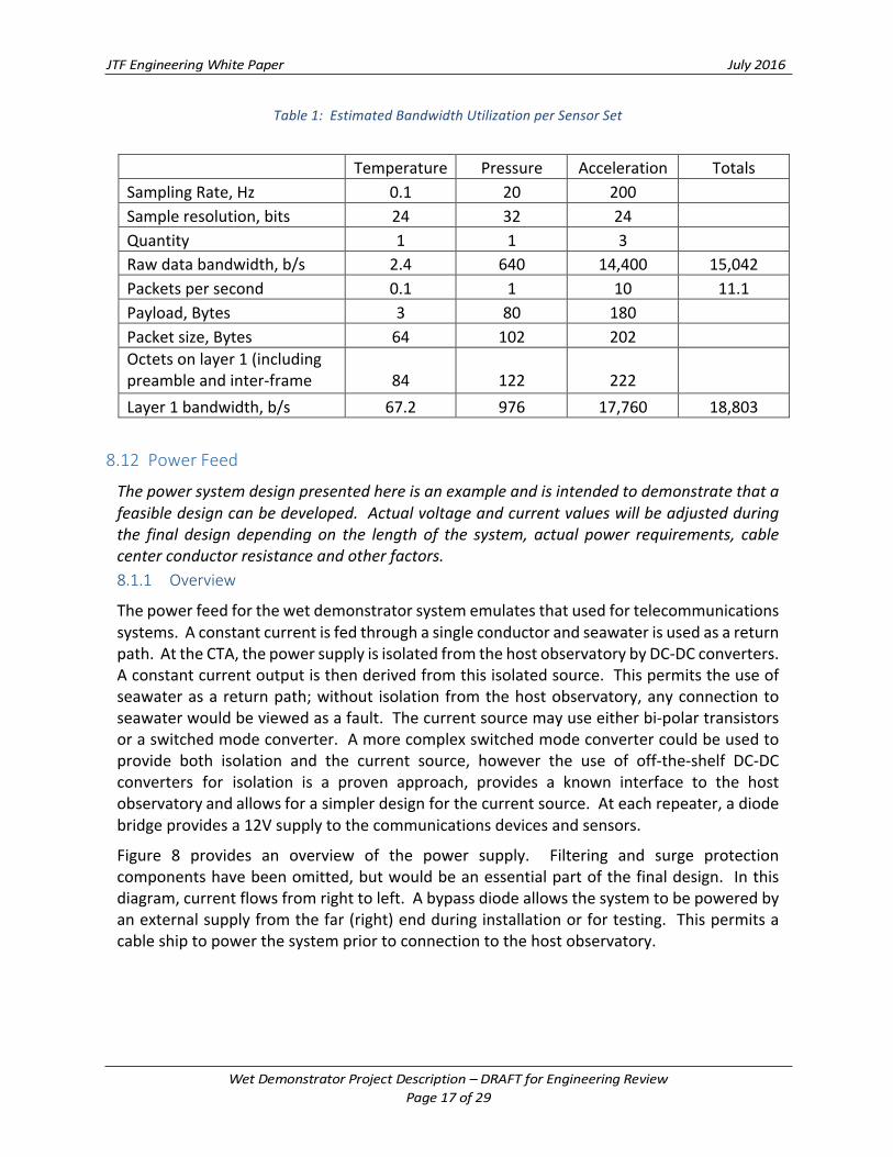
Table1:EstimatedBandwidthUtilizationperSensorSet
Temperature Pressure Acceleration TotalsSamplingRate,Hz 0.1 20 200
Sampleresolution,bits 24 32 24
Quantity 1 1 3
Rawdatabandwidth,b/s 2.4 640 14,400 15,042Packetspersecond 0.1 1 10 11.1Payload,Bytes 3 80 180
Packetsize,Bytes 64 102 202
Octetsonlayer1(includingpreambleandinter-framegap)
84
122
222
Layer1bandwidth,b/s 67.2 976 17,760 18,803
8.12 PowerFeedThepowersystemdesignpresentedhereisanexampleandisintendedtodemonstratethatafeasibledesigncanbedeveloped.Actualvoltageandcurrentvalueswillbeadjustedduringthe final design depending on the length of the system, actual power requirements, cablecenterconductorresistanceandotherfactors.8.1.1 Overview
Thepowerfeedforthewetdemonstratorsystememulatesthatusedfortelecommunicationssystems.Aconstantcurrentisfedthroughasingleconductorandseawaterisusedasareturnpath.AttheCTA,thepowersupplyisisolatedfromthehostobservatorybyDC-DCconverters.Aconstantcurrentoutputisthenderivedfromthisisolatedsource.Thispermitstheuseofseawaterasareturnpath;without isolationfromthehostobservatory,anyconnectiontoseawaterwouldbeviewedasafault.Thecurrentsourcemayuseeitherbi-polartransistorsoraswitchedmodeconverter.Amorecomplexswitchedmodeconvertercouldbeusedtoprovide both isolation and the current source, however the use of off-the-shelf DC-DCconverters for isolation is a proven approach, provides a known interface to the hostobservatoryandallowsforasimplerdesignforthecurrentsource.Ateachrepeater,adiodebridgeprovidesa12Vsupplytothecommunicationsdevicesandsensors.
Figure 8 provides an overview of the power supply. Filtering and surge protectioncomponentshavebeenomitted,butwouldbeanessentialpartofthefinaldesign. Inthisdiagram,currentflowsfromrighttoleft.Abypassdiodeallowsthesystemtobepoweredbyanexternalsupplyfromthefar(right)endduringinstallationorfortesting.Thispermitsacableshiptopowerthesystempriortoconnectiontothehostobservatory.

Figure8:OverviewofPowerFeeding
Inthisapplication,constantcurrentpowerfeedinghasanumberofadvantagesoverconstantvoltagepowerfeeding.Onlyasingleconductorisrequiredinthecable.Aconstantvoltagesystemwouldrequiretwoconductorsoraseaearthateachrepeater.Thepowersupplyineachrepeaterreceivesthesamecurrent,whereasaconstantvoltagefeedatoneendofthecablewoulddeliveradifferentsupplyvoltagetoeachrepeaterduetoresistivelossesinthecable.Thepowersupplydesignisrelativelysimpleandcanbebuiltinsmallvolumeswithoutalargedevelopmentcost.
Theelectronicsandsensorsineachrepeaterarenotisolatedfromthepowersupplyand,asaresult,arebiasedwithrespecttoseawaterbywhateverthecablevoltagehappenstobeateachrepeater.Forthewetdemonstrator,thisvoltageshouldnotexceed300V.Inanactualtelecommunications system, this could be as much as 15kV. This is one of the criticaldifferencesbetweenthewetdemonstratorandaworkingSMARTcable;isolatingthesensorsfromthecablevoltageisanessentialaspectofanyfuturedesigneffort.
8.1.2 IsolationStage
TheisolationstageintheCTAisconstructedfromastackofDC-DCconverterswiththeoutputsinseries.Thismethodhasbeenusedinotherobservatorysystemsandsensordesigns.Theuseofoff-the-shelfDC-DCconverterswithknownisolationcharacteristicsisexpectedtobeeasierthandevelopingandprovinganewisolatedpowersupplydesign.Thedesiredoutputvoltage issetbythenumberofDC-DCconvertersused;anexampleisillustratedinFigure9.Lowpassfiltersarenormallyaddedtoboththeinputandoutputsidesoftheconverters,thisisnotshownhere.Acircuitboarddesignedforsixoreightconverterscanbepopulatedasneededoncethefinaldesignvoltageisselected.
Cathode(MMO electrode)
12VAnode
(Cable End)
Isolation
375-400V supply
Current Source
BypassDiode
Hosting Observatory
CTA
Repeater 1 Repeater 2 Repeater 3
12V 12V(+)
(-)i

Figure9:DC-DCIsolation
8.1.3 CurrentSource
Figure10shows twosimplecurrent sourcecircuits,onebasedonabipolar transistor, theotherusinga switchedmodepower supply. A current sourceusingabipolar transistor isregulatedbytheZenerdiode,operatesinsteadystateandisstraightforwardtoanalyzeanddesign,butsuffersthedrawbackofbeingrelativelyinefficient;anyexcessvoltagenotneededto drive the current loop is dissipated as heat. The switched mode design requiresdevelopmentofaPulseWidthModulation(PWM)controlcircuitdrivenbyacurrentsensor;this canbebasedaround readily available integrated circuits. Apractical implementationwouldincludefilteringelementsandmayaddadditionaltransistorsforredundancy,increasedgain,ortomoreeasilydissipateheat.Amorecomplexflybackconverterdesigncouldalsobeused. Regardless of the design chosen, the development effort required is clearlymanageable.
Figure10:ExampleCurrentSourceCircuits
Isolated Output (to Current Source
400V-48VDC-DC
Converter
400V-48VDC-DC
Converter
400V-48VDC-DC
Converter
400VDCInput
1
2
N
Vin
I
VinI
0V 0V
PWM Control
a)Bi-polartransistor b)Switchedmode

8.1.4 PowerSupplyDesign:LineCurrent
Thelinecurrentprovidedbythepowersupplymustbesufficienttopowerallsensorsandelectronicsintherepeaterhousing.Table2providesaninitialestimateofthelinecurrentbasedonpublishedspecifications.Alldevicesoperatefromthe12VsupplywhichisregulatedbytheZenerdiode.
Table2:ExampleLineCurrentCalculation
Device mA@12VEthernetSwitch 300SerialServer 120TemperatureSensor&Electronics 6PressureSensor&Electronics 32AccelerometersandElectronics 125TotalRequiredCurrent 583LineCurrent 625
Based on these values, a line current between 600 and 625mAwould be selected. Thispreliminaryestimate(conveniently)resultsina1voltdropperkilometerofcablegiventheconductor resistance of 1.6 ohms/km. Establishing working ranges and tolerances is anecessarypartofthedetailedsystemdesign.NotethatanyexcesscurrentisdissipatedasheatintheZenerdiode. Inthisdesign,thepowerdissipatedbytheZenershouldnotexceed2W;10WZenerdiodesarecommerciallyavailable.
8.1.5 PowerSupplyDesign:VoltageDrop
Thepowersupplyisthelimitingfactorinboththecablelengthandthenumberofrepeaterhousings.Thetotalvoltagedropmustnotexceedthecapabilityofthecurrentsource.Thevoltagedropinthecableisgivenby:
𝑉=𝐿*𝐼*𝑅+𝑁*𝑆+𝐵+Z
Where
𝑉=𝑇𝑜𝑡𝑎𝑙𝑉𝑜𝑙𝑡𝑎𝑔𝑒
𝐿=𝐶𝑎𝑏𝑙𝑒𝐿𝑒𝑛𝑔𝑡ℎ𝑖𝑛𝑘𝑚𝐼=𝑃𝑜𝑤𝑒𝑟𝐹𝑒𝑒𝑑𝐶𝑢𝑟𝑟𝑒𝑛𝑡𝑅=𝐶𝑎𝑏𝑙𝑒𝑅𝑒𝑠𝑖𝑠𝑡𝑎𝑛𝑐𝑒𝑖𝑛𝛺/𝑘𝑚𝑁=𝑁𝑢𝑚𝑏𝑒𝑟𝑜𝑓𝑟𝑒𝑝𝑒𝑎𝑡𝑒𝑟ℎ𝑜𝑢𝑠𝑖𝑛𝑔𝑠𝑆=𝑉𝑜𝑙𝑡𝑎𝑔𝑒𝐷𝑟𝑜𝑝𝑝𝑒𝑟𝑅𝑒𝑝𝑒𝑎𝑡𝑒𝑟𝐻𝑜𝑢𝑠𝑖𝑛𝑔𝐵=𝑉𝑜𝑙𝑡𝑎𝑔𝑒𝑟𝑒𝑞𝑢𝑖𝑟𝑒𝑑𝑡𝑜𝑏𝑖𝑎𝑠𝑡ℎ𝑒𝑐𝑢𝑟𝑟𝑒𝑛𝑡𝑠𝑜𝑢𝑟𝑐𝑒𝑍=𝑂𝑡ℎ𝑒𝑟𝑣𝑜𝑙𝑡𝑎𝑔𝑒𝑙𝑜𝑠𝑠𝑒𝑠,𝑓𝑜𝑟𝑒𝑥𝑎𝑚𝑝𝑙𝑒𝑖𝑛𝑙𝑒𝑎𝑑𝑠𝑡𝑜𝑡ℎ𝑒𝑀𝑀𝑂𝑒𝑙𝑒𝑐𝑡𝑟𝑜𝑑𝑒

Table 3 provides a preliminary voltage drop calculation for a system with four housingsseparatedby50km.Thefirsthousingis10kmfromtheCTAanda10kmtailisallowedafterthefourthhousing.Thisexamplemeetsorexceedstherequirementsofthewetdemonstratorand is intended to show that a working design can be realized using readily availablecomponents.
Table3:ExampleVoltageDropCalculation
NumberofHousings 4VoltageDropperHousing 12VTotalVoltageDropinHousings
48V
TotalCableLength 170kmConductorresistance 1.6Ω/kmLineCurrent 625mAVoltageDropinCable 170VBiasvoltageincurrentsource 5VAllowancefordropinCTA 3VTotalvoltagerequiredtosupplycurrentsource
226V
Inthisexample,theisolationstagecouldbeconstructedfromfive48Vconvertersprovidingasource voltage of 240V. Note that the current source based on bipolar transistorsmustdissipateanyexcessvoltageasheat.Forthisreason,thenumberofconvertersintheisolationstageshouldbematchedtotheplannedcablelength.Aswitchedmodeconverterdoesnothavethislimitation.Ifthesystemisintendedtobeextended,thenacurrentsourcewithawideoutputrangewouldneedtobedeveloped.
8.1.6 PowerSupplyDesign:OtherConsiderations
Thepowersupplydesignproposedhereusesalimitednumberofcomponentsandisintendedto be both simple and robust. Achieving robustness in practice is highly dependent oncomponentselection.Allcomponentsshouldberatedwellinexcessoftheexpectedvoltages,currents, and power dissipation. Proper heat sinking is essential. Simulated overloadconditionsshouldbetestedduringtheprototypestage.
8.13 RepeaterHousingMechanicalandThermalConsiderations
Alldevicesplaced insidetherepeaterhousingmustbemountedonasuitablechassis. Allcomponentsmustbeevaluatedtodeterminewhetherheatsinkingisrequired.Mechanicaldesignofachassisandthermalmodelingarecriticalaspectsofthesystemdesign,butshouldbe straightforward. Thermal modeling can be performed using appropriate softwarepackages. Thechassis shouldbedesignedso it canbemanufacturedusingbasicmachinetools.

8.14 DataManagement
ThehostingobservatoryisrequiredtoprovidedatamanagementservicesforTemperatureandPressuresensors.Tri-axialaccelerometerdatamaygatheredbythehostingobservatoryorbestreamedtoaseismicdatacenter.Datafromtiltsensors,ifincluded,wouldalsobetheresponsibilityofthehostingobservatory.
8.15 SparesTwotothreesetsofsparesshouldbeproducedforallcustommanufactureditems,includingcircuitboards,internalchassis,andtheprotectiveinstrumentpods,asre-manufacturingcanbe logistically difficult and expensive. Off the shelf items should not be spared, becausereplacementscanbeacquiredasnecessarytosupportrepaircruises.Notethatitemswhichmaybediscontinuedshouldbesparedifasuitablereplacementcannotbeidentified.
Iffundsareavailableforanadditional,completedrepeaterhousing,itisrecommendedthisbe deployed as part of the initial system rather than retained as a spare. The additionalhousing increasesthequantityandvalueofthedatacollectedwhileactingasan“on-line”spare.Ifanysensorsorcommunicationsdevicesfail,havingadditionalunitsontheseabedmaystillallowthewetdemonstratortocompleteitsobjectives.
9 ProjectDescriptionThissectionprovidesahighleveldescriptionofeachoftheactivitiesthatmustbecarriedouttosuccessfullycompletethewetdemonstratorproject.Aswiththedesignitself,theprojectdescriptionisnotintendedtobeafinalsolution,butrathertoillustratethatfeasiblesolutionsare readily available. Each project activity should be manageable, with clearly definedrequirements, interfaces, and have realistic methods formeeting its requirements. Eachactivitycanbethoughtofasaseparatescopeofwork;however,asingleentityorsuppliermayperformseveraloftheseactivities.
9.1 Owner
Theownerofthewetdemonstratorisexpectedtobeeitheraresearchinstitutionorspecialpurposeentity(SPE).Theownerreceivesanddisbursesfundsfordevelopment,construction,installation and operation of the system. Title to the system is vested in the owner.IntellectualPropertyrequiredtoconstructoroperatethewetdemonstratormustbelicensedtotheowner.
9.2 HostObservatoryorSystem
The host observatory or system provides an off-shore interface that delivers power andcommunicationstothewetdemonstratorfromashorestation.Thehostmaybeasciencearray, a commercial telecommunications cable, or an out-of-service cable. The hostmayprovideotherservicesincludingdesigninput,laborworkshopfacilities,datamanagement.Itispossible,butnotmandatory,thatthehostandownerwillbethesameentity.

9.3 ProjectManagement
Projectmanagementcoordinatesallotheractivitiesbyfacilitatingcommunication,preparingroutinereports,maintainingaprojectplanofwork,andtrackingaction item lists. Projectmanagement also controls the project budget, places orders, and approves payment tosuppliers and contractors. Wherenecessary, projectmanagement negotiates agreementsandcontractstosupplyproductsorperformservices.
9.4 DesignAuthority
Thedesignauthorityactsasatechnicaladvisortotheprojectmanager.Alldesignwork,testplans, procedures results, and any technical changes must be approved by the designauthority.Asthisprojectrequiresmanyareasofexpertise,thedesignauthoritymustbeabletocalluponindividualswithsuitableexpertiseasrequired. Thedesignauthoritymaybeapartoftheprojectmanagementorganizationoraseparate,contractedentity.
9.5 HealthSafetyandEnvironment
Health,SafetyandEnvironmental(HSE)reviewisnowanessentialpartofallmajorprojects.HSE ensures that all project activities are carried out in a manner that is safe andenvironmentally sound. HSE may be part of the project management organization or aseparate,contractedentity.
9.6 QualityAssurance
Qualityassuranceverifiesthatallprojectactivitiesarecarriedoutinaccordancewithwritten,traceableprocedures.Qualityassurancemaybepartoftheprojectmanagementorganizationoraseparate,contractedentity.
9.7 Permitting
Permitting activities center around obtaining lawful permissions to perform any work.Permittingmayalsoincludeliaisonactivitieswithotherseabedusers,suchasfishermenandthosewithhydrocarbonormineralrights.Permittingmaybepartoftheprojectmanagementorganizationoraseparateentitymanagedundercontract.
9.8 SiteSelectionandMarineSurvey
Selectionof a suitable sitemustoccur early in theproject so thatother activities arenotdelayedbyunknowns.Permitting,manufacturedcablelength,cabletype,andCTAdesignalldependonlocationandseabedconditions.Apreliminarycablerouteisselectedpriortosurveyandadjustedbasedonsurveyresults.
In the interests of accurately representing the installation procedures for telecom cable,similarmarinesurveydatashouldbecollected.Inwaterdepthsover1,000m,thisisusuallylimitedtoswathbathymetrybutmayincludesidescansonarinareaswheretheseabedisknownorsuspectedtobehazardous.
Giventherelativelyshortroutelengthofthewetdemonstrator,itwouldbebeneficialtosharemobilizationcostswithothersurveyactivities,whetheraspartoftheobservatoryoperations,sciencecruise,orforanearbycommercialtelecomcable.

9.9 ProvisionofCable,RepeaterHousings,andSystemAssembly
The use of conventional telecommunications cable and repeater housings are central toachievingtheobjectivesofthewetdemonstratordesign. Cableandrepeaterhousingsaretypicallyfurnishedtogetherbyasinglesupplieraspartofanassembledsystem.However,thereisnorequirementthatcableandrepeatersforthewetdemonstratorbefurnishedbythesamesupplier.Thereareseveralcircumstancesinwhichcableandrepeatersmightbeprocuredseparately.Forexample,ifretiredsparecableweremadeavailableatlittleornocost,theexpenseofnewcablecouldbeavoided.Asystemcomprisingrepeaterhousingsfromtwoormoresupplierscouldalsobedevelopedtopermitdemonstrationofdifferentsuppliers’capabilities.
Regardless of how the cable and repeater housings are procured, the wet demonstratorsystemmustbeassembledandtestedpriortodeployment.Theconventionalapproachistoperformthisassemblyandtestinacablefactory,afterwhichthesystemisloadedontothecablelayingvessel.Alternatively,systemassemblymaybeperformedatadocksidefacilityoronboardthecablelayingvessel.Thecable,repeaters,andallnecessaryancillaryequipmentcan be transported by freighter to a convenient location where the assembly work isperformed. Such alternativemethods can provide cost savings (for example, by reducingcable shipmobilization and transit time), but afford less opportunity to correct problemsshouldtheyarise.
Regardless of the exact method used, several events must occur to complete the wetdemonstratorsystem.First,theinternalandexternalcomponentsoftherepeatermustbeassembled,tested,andtherepeaterhousingclosed.Second,therepeaterhousingsmustbecoupledtothecable.Thiscouplingcanconnecttherepeaterdirectlytothesystemcableorashort“tail”maybeusedwhichislaterjointedtothesystemcable.Inthecasewherefinalassemblyoccursoutsideacable factory, the repeaterswillbedeliveredas tailed repeaterassemblies.Next,anyjointingrequiredtocompletethesystemassemblyoccurs.Finally,theassembledsystemistested.
Thelocationandmethodforsystemassemblywilldependonthecapabilitiesofparticipatingsuppliers,thefinalsystemlength,thesystemlocation,andlogisticalfactorssuchascableshiptransitandmobilizationtimes.Atthisstage,thewetdemonstratordesignmustretaintheflexibilitytoallowwhicheverapproachprovidesthemosteconomicapproach.
9.10 CableTerminationAssembly
The cable termination assembly (CTA) which connects the wet demonstrator to the hostobservatory will require a unique design. A one atmosphere housing is required forcommunications and power conversion equipment. Connection to both a wet-mateconnector and the telecommunications cable are required. The assembled CTAmust beinstalledbythecablelayingvesselwithin50meters(ideally10meters)ofthedesiredlocation.Thewet-mateconnectorand itsassociated flying leadmustbemanipulatedbyanROVtocompletetheconnectiontothehostobservatory.
CTAs have been deployed as part of cable ocean observatories and to support oil & gasprojects.Theinclusionofa1atmospherehousingisnottypicalandmayrequiresomedesign

effort. Nonetheless,all requiredcomponentsarecommerciallyavailableorcanreadilybefabricated, including titanium housings, wet mate connectors, couplings to thetelecommunicationscableandframes.
9.11 ProcurementofOff-the-ShelfItems
Many of the components of the wet demonstrator are off-the-shelf items; these includeconnectors, cables, sensors, some of the sensor electronics, Ethernet switches and serialservers.Procurementoftheseitemsisastraightforwardactivity.
9.12 ProvisionofIntegratedSensorPackageandCabling
Inthecasewheretheoff-the-shelfpackagingofthesensorsisnotsuitable,aseparatesensorpackageorpressurecasemustbeprocuredordevelopedasnecessary.Ineithercase,cablesandconnectorsforthetemperatureandpressuresensorsmustbeassembled.Thisworkissimilartothatperformedforsensorsattachedtoexistingobservatories.
9.13 AttachmentHardwareDesignandManufacture
Designandmanufactureofthebootorpodwhichholdsthesensors/pressurecaseandthespiralwraptoretainthesensorcableisthefirstoftwoareasrequiringnewdevelopment.Thisworkincludesselectionandintegrationofasuitablepenetratorfortherepeaterhousingandmustthereforebecloselycoordinatedwiththesupplieroftherepeaterhousings.Thisworkmaybeundertakenbythecablesupplierorsourcedseparately.Ifexistingpartscannotbeadapted,injectionmoldingorsimilarmethodsmustbeusedtomanufacturethesensorpod.(3-Dprintingmaybeused,butisnotessential.)
9.14 PowerSystemDevelopment
Design and assembly of the various power supply components (power isolation, currentsource, andZenerbasedpowersuppliesforeachhousing)isthesecondmajorareaofnewdevelopment.Computermodelingofthepowersystemshouldbeperformedaspartofthedesignprocess;thisisparticularlyusefulforverifyingthepowersystemcandealwithtransientor other abnormal conditions. If suitable expertise is not available within the projectorganization,thenacontractororconsultantmayberetainedtoperformthedesign,managetheassembly,andoverseetestingofthesecomponents.Individualswithsuitableexpertisehaveparticipatedinpreviousobservatoryprojects.
9.15 CommunicationsSystemDesign
The communications system does not include any custom components. Specification,purchase,andconfigurationofthecommunicationscomponentsandpreparationofwiringdiagramsare straightforwardtasksthatcanbeperformedbythehostobservatoryorotherprojectparticipant.
9.16 MechanicalandThermalDesign
MechanicaldesignandthermalanalysisofthechassisformountingcomponentsinboththeCTAandrepeaterhousingisthethirdandfinalarearequiringcustomdevelopmentwork.Aswith the power system development, this could be performed by any one of the project

participantsoranoutsideexpert.Manufacturingandassemblyofthechassisrequiresaccess(andknowledgeof)amachineshop.(CNCor3-Dprintingmaybeused,butarenotessential.)
9.17 InitialBenchTestsItisvaluabletobeginbenchtestsofanyavailablecomponents,evenbeforedesignworkisfinishedonotheraspectsoftheproject. Thistestingservestoidentifyissuesearly,beforechangesandcorrectionsbecomecostlyandtimeconsuming.
Thecommunicationsequipmentandsensorsareoff-theshelfitems;arepresentativesetofthisequipmentshouldbepurchasedearlyintheproject,configured,debugged,andplacedon-lineinatestenvironmenttosupportdevelopmentofinterfaces(drivers)withinthedatamanagementsystems.
Powerboardsmustbetestedandvalidatedattheprototypestage,inparticularsurgetestingandotherabnormalconditionscanbetestedtovalidatethecomputermodel.
Similarly, an earlymockup of anymechanical itemswill ensure that finished units can beproperlyassembled.Thiscanalsoservetovalidatethermalmodels.
9.18 PreliminaryIntegration
Followingcompletionofthedesign,allcomponentsexceptthecableandhousingsshouldbeintegratedintoaworkingsystemandtestedfromend-to-end.Thistypeoftestingistypicallyperformedinalaborworkshopsettinganditwouldbeappropriateforthehostobservatorytoprovidefacilitiesforthisstageoftesting.Fiberopticattenuatorsandpowerresistorscanbeusedtosimulatethecablesbetweeneachhousing.Thiswillensurethatworkingunitsaredeliveredtotherepeaterhousingmanufacturingforinstallationintothehousings.Thisalsoprovidesafinalopportunitytovalidandreconfigurethesystembeforeitissealedintotherepeaterhousings.
9.19 CablePlantIntegrationAtthecableplant,theinternalcomponentsareinstalledintotherepeaterhousings,andthehousingssealed.Thenthecouplingswithattachtherepeaterstothecablearemadeup.Thesensorpodsmustbeattachedatthisstage.Followingintegration,thesystemcanagainbepoweredandtested.Thecompletedsystemisthenloadedtoacableshiporfreighter.
In the casewhere final assemblyoccurs dockside, the integrated and tailed repeaters areshipped from the repeater factor to the assembly facility where the remaining steps areperformed.
9.20 InstallationInstallation activities include loading the finished system onto the cable laying vessel,shipboard test, placement of the CTA, and surface laying of the system. The system isdesignedsuchthatitcanbepoweredandmonitoredfromthefarend(theendfarthestfromtheCTA)during installation. The shipboardPFE isadequate for thisandonlyanEthernetswitchandlaptopcomputerarerequiredtomonitorthecommunications.
As with themarine survey, it is beneficial if the installation work can be shared with or

“piggybacked”onalargerprojecttoreducemobilizationcosts.
ConnectionoftheCTAtothehostobservatoryrequiresanROV.Thiscanbeperformedbyaresearch vessel during a science cruise; any vessel which is adding or maintaining otherobservatorysensorswillhaveasuitableROVonboard.OneormorerepeaterhousingscanbeinspectedbytheROV,eitherduringthesameorasubsequentdive.
9.21 Commissioning
System commissioning is performed by powering up and verifying that all devices areoperating.Abrieftestmustbeconductedbeforereleasingthecableshipandalongertermtestmaybeperformedbeforedataisreleasedforuse.
ROVinspectionofatleastonesensorsiteisastatedobjectiveofthewetdemonstratorsystemand should be performed as soon as practical after installation. Re-inspection at annualintervalsshouldbeconductedtoallowsettlingandsedimentdeposittobeobserved.
9.22 DataManagement
Thehostingobservatoryisresponsiblefordatamanagement,includingdataqualitycontrol,of sensor and pressure data. Accelerometer data may be streamed to a seismic datarepository.
9.23 Summary
A diverse set of resources and skills are needed to develop the wet demonstrator. Thisdescription is a first, high level, summary of the necessary capabilities. This list is notexhaustiveandotherresourcesmayberequiredastheprojectdevelops.Table4providesasummaryoftheprojectactivitiesbyroleandtypeofactivity.
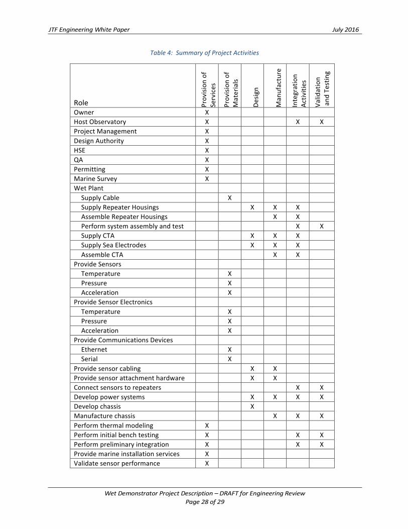
Table4:SummaryofProjectActivities
Role Provision
of
Services
Provision
of
Materials
Desig
n
Man
ufacture
Integration
Activ
ities
Validation
and
Testin
g
Owner X HostObservatory X X XProjectManagement X DesignAuthority X HSE X QA X Permitting X MarineSurvey X WetPlant
SupplyCable X SupplyRepeaterHousings X X X AssembleRepeaterHousings X X Performsystemassemblyandtest X XSupplyCTA X X X SupplySeaElectrodes X X X AssembleCTA X X
ProvideSensors Temperature X Pressure X Acceleration X
ProvideSensorElectronics Temperature X Pressure X Acceleration X
ProvideCommunicationsDevices Ethernet X Serial X
Providesensorcabling X X Providesensorattachmenthardware X X Connectsensorstorepeaters X XDeveloppowersystems X X X XDevelopchassis X Manufacturechassis X X XPerformthermalmodeling X Performinitialbenchtesting X X XPerformpreliminaryintegration X X XProvidemarineinstallationservices X Validatesensorperformance X

10 OperationsandEvaluationThewetdemonstratorisdesignedforcontinuousoperationwithnooperatorintervention.Sensorsandcommunicationsdevicesinthewetdemonstratoraremonitoredcontinuouslybythehostobservatory’sdatamanagementsystem.
In the event of a loss of power or communications, these should be restored as soon aspracticalandthewetdemonstratorsystemwillautomaticallyrestart.
Inthecaseofa faultordamagetothewetdemonstrator,acableshipwillberequiredtorecoverandrepairthefaultedportion.Afailedrepeaterhousingcanbecutoutofthesystem,allowingtheremaininghousingstocontinueoperation.
11 PlanofWorkDevelopmentofadetailedplanofworkistheresponsibilityoftheprojectmanager.Thereisinsufficientinformationatthisstagetoprovideaplanofwork.Arealisticexpectationisforaprojectofeighteentotwenty-fourmonthsduration. Takingadvantageofopportunitiestosharevesselmobilizationmayhaveasignificantimpactontheschedule.
12 BudgetMaintaining a detailed budget is the responsibility of the project manager. There isinsufficient information at this stage to provide a complete project budget. A realisticexpectation is for a project cost between $5 and $15 million, with the most significantvariables beingmobilization costs for themarinesurveyandcable layvessels followedbyengineeringanddevelopmentcostsforitemswhicharenotavailableoff-the-shelf.
~end~