semi-rigid joint of timber-concrete composite beams with ... · pdf filesemi-rigid joint of...
TRANSCRIPT
491
WOOD RESEARCH 59 (3): 2014 491-498
SEMI-RIGID JOINT OF TIMBER-CONCRETE COMPOSITE
BEAMS WITH STEEL PLATES AND CONVEX NAILS
Petr Agel, Antonín Lokaj Technical University of Ostrava, Faculty of Civil Engineering Department
of Building StructuresOstrava, Czech Republic
(Received April 2014)
ABSTRACT
Thanks to good quality of both materials are today composite timber-concrete constructions suitable solution for new buildings and reconstructions of ceiling constructions of residential or civil buildings. In praxis can be found many ways how to create connection (joint) of timber beam and concrete slab. The methods of coupling are more and more sophisticated which carries bigger demands on control of implementation and technological practice. This paper describes laboratory tests and numerical and analytical modelling of timber-concrete composite beams with semi-rigid joints made of steel plates and convex nails.
KEYWORDS: Joint, spruce, concrete, composite, beam, slab, steel, plate, nail.
INTRODUCTION
Timber ceiling constructions were used profusely for individual housing and civil constructions in the past. These constructions were favoured especially for their light weight, immediate static action and low technological demands on implementation. As time went, timber horizontal constructions were pushed away by prefabricated concrete panels with bigger carrying capacity and better acoustic properties.
Today there is increasing demand on economy, ecology and sustainable development of construction. Timber and materials on its base are of organic origin and fulfil all demands stated above. Wood and concrete composites, which are connected by good qualities of both material, appear to be very appropriate for modern and ecological construction. These composite ceiling constructions are largely made by timber ingots (beams), which interact with reinforced concrete slab. That way the composite T-section is created, which with good design can use concrete in compressed part and timber in tensile and bending part. Interaction of both parts of section and with that connected proper distribution of tension on section height must be secured by coupling means.

492
WOOD RESEARCH
Nowadays it is possible to use large variety of connective means (Steinberg et al. 2003) for joining timber beam and reinforced concrete slab. It can vary from simple methods of joining by steel nails or pikes, all the way to glued batten or trestles (Manaridis 2010). Steel joint does not always have to be used as a coupling mean. In literature there are also described different kinds of carpenter adjustments of upper surface of timber beam working in a way, that it creates natural trestles or notches working as a coupling means. Another interesting way of joining is using adhesive batten made of waterproof plywood. These ways of joining without steel element are especially interesting in terms of fire resistance. By using sophisticated methods of joining, e.g. glued steel batten, it is possible to achieve almost rigid connection. On the other hand, coupling elements based on dowel type coupling means, such as joining by nails, screws, or steel perforated plates and convex nails, creates a semi-rigid joint (Agel and Lokaj 2012).
The aim of this paper is to verify possibilities and functionality of technologically simple and at the same time sufficiently effective joint of timber-concrete ceiling or roof beams by steel perforated thin sheets, that are nailed to the timber element by convex nails and embedded in reinforced concrete slabs.
The condition for the selection of coupling means was their common availability and their easy application in opposite to other methods of joining (e.g. glued battens, milled grooves and others). In many cases simple joint of concrete and timber was more effective than more technologically complicated methods (Ahmadi 1993, Dias et al. 2007, Poštulka and Sandanus 1999).
Tests of timber-concrete composite beams, which were designed to meet the formerly defined aims, are described below. Examined elements show one part of ceiling construction made of two timber beams joined with reinforced concrete slab. The shape of this segment resembles TT panel.
MATERIAL AND METHODS
Before doing the tests on real samples it was needed to know at least approximate values of strain, at which samples get damaged. It was possible to get these values by creating numerical FEM model.
For these tests shell-beam model was created in software SCIA Engineer. Model was built this way for easy manipulation with location and number of coupling means.
Fig. 1: Example of shell-beam model of timber-concrete composite element made in software SCIA Engineer.
Fig. 2: Placement of loads in model situation.
Numerical model is made of two parallel rods with axial distance of 900 mm that are hinged on both ends just like when doing four-point bending test. Rods were connected to 60 mm thick
493
Vol. 59 (3): 2014
plate with two types of short rods. First type had the real measures, deformational parameters and boundary conditions typical for used coupling means (steel plate and convex nails). Second type simulates friction between timber beams and concrete plate, which occurs in real situation.
Model was loaded similarly to the four-point bending test, it means by four vertical forces located in a thirds of span (Fig. 2).
Value of the forces was gradually increased until the greatest normal stress in timber part of the cross section reached the value of 24 MPa, which was considered as the limit of carrying capacity of cross section. The total force for damaging the real sample was set this way. Values of forces set by simulation was set to FA,D= 4×F1= 4×15.2 = 60.8 kN (samples A, D with 32 pieces of coupling means on panel) and FB,C= 4×F1= 4×20.6 = 82.4 kN (samples B, C with 64 pieces of coupling means on panel).
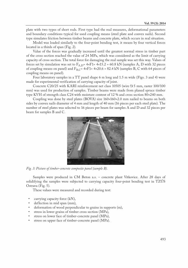
Four laboratory samples in a TT panel shape 6 m long and 1.5 m wide (Figs. 3 and 4) were made for experimental verification of carrying capacity of joint.
Concrete C20/25 with KARI reinforcement net class 10505 (wire 5 mm, raster 100/100 mm) was used for production of samples. Timber beams were made from planed spruce timber type KVH of strength class C24 with moisture content of 12 % and cross section 80×240 mm.
Coupling was done by steel plates (BOVA) size 160×160×2.0 mm nailed to beams on both sides by convex nails diameter of 4 mm and length of 40 mm (16 pieces per each steel plate). The number of steel plates was selected to 16 pieces per beam for samples A and D and 32 pieces per beam for samples B and C.
Fig. 3: Picture of timber-concrete composite panel (sample B).
Samples were produced in CM Beton a.s. – concrete plant Vítkovice. After 28 days of solidifying the samples were subjected to carrying capacity four-point bending test in TZÚS Ostrava (Fig. 5).
These values were measured and recorded during test:
• carryingcapacityforce(kN),• deflectioninmidspan(mm),• deformationofwoodperpendiculartograinsinsupports(m),• stressinlowergrainsoftimbercrosssection(MPa),• stressonlowerfaceoftimber-concretepanel(MPa),• stressonupperfaceoftimber-concretepanel(MPa).

494
WOOD RESEARCH
Fig. 4: Shape of samples timber-concrete composite TT panels.
Fig. 5: Scheme of bending test of timber-concrete TT panels.
RESULTS AND DISCUSSION
Results of the tests were recorded in diagram for relation of deflection w (mm) on total force F = 2×F1 (Fig. 6).
Fig. 6: Scheme of bending test of timber-concrete composite TT panels

495
Vol. 59 (3): 2014
To calculate the real values of carrying capacity of nails connection it is needed to set the density of timber of used samples. Measures will be done according to reference (ČSN 49 0108, 1993) on 30 samples of size approximately 30×50×1000 mm, which were acclimatized in moisture between 8-12 %. Moisture of the samples was measured by hygrometer. Density at 12 % moisture will be set from measurement results according to:
(1)
where: ρw - density of timber at set moisture, mw - weight of timber at set moisture, aw - height of cross section at set moisture, bw - width of cross section at set moisture, lw - length of timber sample at set moisture.
From density at set moisture it was possible to calculate density at 12 % moisture that is prescribed for timber tests.
(2)
where: ρw - density of timber at set moisture, ρ12 - density of timber at 12 % moisture, K - coefficient of volume shrinkage (K=0.85.10-3), W - moisture of the sample. In the analytical calculation of carrying capacity of the timber-concrete cross section it was
used average density of timber ρw=474.85 kg.m-3 for setting the carrying capacity of joints. On 30 samples of planed spruce timber type KVH (used in timber-concrete panels) with size
30×50×1000 mm was done four-point bending test (Figs. 7 and 8). From test results on 30 samples it was possible to set f lexural modulus Em.
Fig. 7: Scheme of the timber sample four-point bending test.
Fig. 8: Four-point bending test in FAST VŠB-TU Ostrava laboratory.

496
WOOD RESEARCH
(3)
where: Ei.- elastic modulus of tensile and compression for 20, 30 and 40 % of total force, Fi.- 20, 30 and 40 % of total force, L - distance between supports, Iy - sample moment of inertia, ui - immediate deflection under load burden at 20, 30 and 40 % of total force, κ-coefficient, A-sectional area of the sample.
The average value of elastic modulus Em=22.73 GPa was used. In the analytical calculation of carrying capacity of the timber-concrete cross section. Average value was calculated from statistic corpus of 30 measures, where standard deviation is s = 8.561 GPa and coefficient of variation is υ =37.63 %. Average value was used to compare results of tests of real samples in small number with analytical calculation. By using 5 % quantile of elastic modulus it would create deviation from real measured values.
A set of six concrete cubes with size 150×150×150 mm for every single panel was prepared from concrete mixture, used in production of timber-concrete panels. Cubes were compacted by vibrations on vibration table in the area of concrete plant Vítkovice. After 28 days of solidifying cubes were grinded on two opposite sides and submitted to pressure test in laboratory (Fig. 9).
Fig. 9: Concrete sample test for getting elastic modulus of tension and compression.
Fig. 10: Damage of finger joint of timber beam sample C.
In the analytical calculation of carrying capacity of the timber-concrete cross section there was used the average value of elastic modulus and compressive strength of concrete Emean=23.96 GPa and fc,mean,k = 27 MPa. Average values were taken from statistic corpus of these parameters:
• Elasticmodulus: nE.= 15; sE.= 4.24 GPa; vE =17.69 %• Compressivestrength: nf.= 23; sf.= 3.41 GPa; vf.=1.64 %
Analysis of the construction was made to same static scheme as the four-point bending test of timber-concrete composite panels. Calculation follows the procedure described in literature (Timber Engineering STEP 2 1995, ČSN EN 1995-1-1 2006, Sandanus 2007) with use of the effective stiffness on the cross section.
Assessment of construction was calculated in MS-Excel table for easier changing input data.

497
Vol. 59 (3): 2014
Thanks to that the maximal possible load force F1 on timber-concrete panels A, D and B, C were obtained (results - see Tab. 1).
Tab. 1: Timber - concrete composite panels carrying capacity.
SampleSteel plates per
beam (pcs.)Ftot,test (kN) Ftot,an(kN) Ftot,FEM(kN)
A,D 16 59.3 72.6 60.8B,C 32 81.2 76.4 82.4
Ftot,test - total load force during four-point bending test (higher value),Ftot,an - total load force in analytical calculation during four-point bending test,Ftot,FEM - total load force during four-point bending test in FEM Model.
Fig. 11: Damage of timber beam in knot. Fig. 12: Damage of timber beam along grains.
Damage occurred in all samples in drawn grains of timber beams (Figs. 10, 11 and 12). After the beams had been collapsed, concrete slab was disrupted in the place burdened by tension. The joints were not damaged. Analytical calculation and FEM model simulation show the same results.
CONCLUSIONS
Comparison of results from analytical calculation indicates, that by doubling the number of coupling means, according to standard method, the total cross section carrying capacity does not significantly increase (about 5.2 %) The difference between carrying capacity of types A, D and B, C within the FEM model is relatively large (35 %). Result of four-point bending test on panel B indicates that FEM model simulation is closer to the reality. This hypothesis is not possible to confirm by test on the panel C. Its carrying capacity was much lower than expected. It was probably caused by poor quality of finger joint in timber beam, where the damage happened.
ACKNOWLEDGMENT
This outcome has been achieved with funds of Conceptual development of science, research and innovation assigned to VSB - Technical University of Ostrava by Ministry of Education Youth and Sports of the Czech Republic.

498
WOOD RESEARCH
REFERENCES
1. Agel, P., Lokaj, A., 2012: Laboratory tests of load bearing capacity of mechanical joint of composite timber concrete beam. In: Transactions of the VŚB- Technical universtity of Ostrava, Civil Engineering Series.
2. Ahmadi, B.H., 1993: Behavior of composite timber-concrete f loors. Journal of structural engineering 109(11): 3111-3130.
3. ČSN 49 0108, 1993: Timber-density analysis.4. ČSN EN 1995-1-1, Eurocode 5 - 2006: Design of timber structures: Part 1-1: General -
Common rules and rules for timber structures.5. ČSN EN ISO 6892-1- 2010: Metallic materials - Tensile testing. Part 1. Method of test at
room temperature.6. Dias, A.M.P.G., Lopes, S.M.R., Van de Kuilen, J.W.G., Cruz, H.M.P., 2007: Load-
carrying capacity of timber-concrete joints with Dowel-type fasteners. Journal of structural engineering 133( 5): 720-727.
7. Lokaj, A., Vavrušová, K., Rykalová, E., 2011: Application of laboratory tests results of dowel joints in cement-splinter boards VELOX into the fully probabilistic methods (SBRA method). Applied Mechanics and Materials 187(1): 95-99.
8. Mandaris, A., 2010: Evaluation of timber concrete composite f loors. Lund University. Pp 131.
9. Poštulka, J., Sandanus, J., 1999: Berechnungsverfahren für eine Holz-Beton-Vergunddecke mit Nägeln als vergindungsmittel. Bautechnik 76(11): 1026-1030.
10. Sandanus, J., 2007: Parametric study of the factors affecting the resistance of a composite timber-concrete cross-section. Wood Research 52(3): 109-114.
11. Steinberg, E., Sele, R., Faust, T., 2003: Connectors for timber-lightweight concrete composite structures. Journal of structural engineering 129(11): 1538-1545.
12. Timber Engineering STEP 2, 1995: Centrum Hout, The Netherlands.
Antonín Lokaj, Petr AgelTechnical University of Ostrava
Faculty of Civil EngineeringDepartment of Building Structures
17. Listopadu 15/2172708 33 OstravaCzech Republic
Correspondig author: [email protected]