semantic server - paulo bravo - centria - universidade nova de
TRANSCRIPT

DEPARTAMENTO DE INFORMÁTICA
Licenciatura em Engenharia Informática
EEOO--KKEESS--BB
SSEEMMAANNTTIICC SSEERRVVEERR
Graduation Report
October 2004
PAULO BRAVO (9224)
ORIENTATION: JOÃO CARLOS MOURA PIRES, PhD
EXTERNAL COORDINATOR RITA RIBEIRO, PhD
INSTUTION: CA3/CRI/UNINOVA


- I -
Acknowledgments
First, I would really like to thank to all CA3 group, which supported me and
integrated me in its team, since the first day.
I want also to thank to my colleges and my special friends for support,
company and good times, during the graduation.
Finally, my special thanks to my family, always with me, giving me always
their best, so I can have a better future.
A todos, obrigado.
Paulo
- II -
Summary
This report describes the work developed during the internship period by
the undergraduate student Paulo Nuno Castro Correia Bentes e Bravo in the
context of the EO-KES-B (Earth Observation domain-specific Knowledge Enabled
Services) project.
The main goal for this project was the development of an online search
system for EO (Earth Observation) products, targeted for both EO expert and
non-expert users. To guide the product exploration, ontologies for the EO
domain and specific user domains were modelled. The search strategy uses an
hybrid approach of free text queries and navigation through concepts in a
domain ontology.
- III -
Index
1 Introduction ______________________________________ 8
1.1 Academic Context _____________________________________________ 8
1.2 Scientific and Technological Context _______________________________ 8
1.2.1 Web Applications ________________________________________ 8
1.2.2 OVERVIEW of ONTOLOGIES for Information Systems: Why use
ontologies? ____________________________________________ 11
1.3 Internship Goals______________________________________________ 13
1.4 Report Structure _____________________________________________ 14
1.5 EO-KES-B Overview ___________________________________________ 15
1.5.1 Global Description ______________________________________ 15
1.5.2 Global Architecture______________________________________ 18
2 Application Survey ________________________________ 20
2.1 Protégé_____________________________________________________ 20
2.2 WordNET ___________________________________________________ 21
2.3 Eclipse 23
2.4 Tomcat _____________________________________________________ 24
2.5 JavaServer Pages Technology ___________________________________ 24
2.5.1 JSP Technology and Java Servlets __________________________ 25
2.5.2 Community Background __________________________________ 26
3 Knowledge Representation __________________________ 27

- IV -
3.1 An ontology-aided approach to EO product search ___________________ 27
3.1.1 A DESIGN PATTERN FOR ONTOLOGY DESIGN _________________ 27
3.1.2 INFORMATION SEARCH IN KES-B: THE GAP FROM USER DOMAIN TO
EO DOMAIN ___________________________________________ 29
3.1.3 Generic Ontology _______________________________________ 31
3.1.4 EO Domain ontology_____________________________________ 35
3.1.5 Water Quality and Maritime Security Domain Ontology__________ 35
3.1.6 The complete model: KES-B Ontology Guided Tour_____________ 36
3.1.7 Strong relation: State - EO Resource – EO Event ______________ 39
3.2 USER ADAPTATION ___________________________________________ 41
3.2.1 WHY AND WHAT TO ADAPT? ______________________________ 41
3.2.2 User-specific adaptation of domain ontology search ____________ 41
4 Development_____________________________________ 46
4.1 First phase – framework configuration/installation ___________________ 46
4.1.1 Installing Tomcat _______________________________________ 46
4.2 Second Phase________________________________________________ 50
4.2.1 Protégé Web Browser ____________________________________ 50
4.2.2 WordNET Web Interface __________________________________ 51
4.2.3 Implementation architecture: _____________________________ 56
4.2.4 SQL Web Interface ______________________________________ 61
4.3 Third Phase _________________________________________________ 61
4.3.1 Java Application ________________________________________ 62
4.3.2 WEB Application ________________________________________ 69
5 Application Presentation ____________________________ 71
5.1 KES-B Ontology Navigation: case studies __________________________ 71
5.2 First Page ___________________________________________________ 72
5.3 Navigation __________________________________________________ 75

- V -
5.4 Search using query ___________________________________________ 78
5.4.1 Search Process _________________________________________ 78
5.4.2 Web application ________________________________________ 79
6 Conclusions ______________________________________ 84
6.1 Developed Work Evaluation _____________________________________ 84
6.2 Future Work _________________________________________________ 84
6.3 Internship Evaluation__________________________________________ 86
7 Bibliography _____________________________________ 87
8 Annexes _______________________________________ 91
8.1 Annex 1 – KES-B Ontology Design Dictionary _______________________ 91

- VI -
Index of Figures
FIGURE 1 - ARCHITECTURE OF THE EO-KES SYSTEM........................................................... 16 FIGURE 2 - PROGRESSIVE FOCALISATION OF THE PROJECT’S DOMAIN.......................................... 17 FIGURE 3 - SPECIFIC SEMANTIC SERVER CURRENT ARCHITECTURE............................................. 18 FIGURE 4 - SPECIFIC SEMANTIC SERVER INTEGRATED ARCHITECTURE......................................... 19 FIGURE 5 - PROTÉGÉ ............................................................................................... 21 FIGURE 6 - WORDNET BROWSER ................................................................................ 22 FIGURE 7 – ECLIPSE................................................................................................ 23 FIGURE 8 - A DESIGN PATTERN FOR ONTOLOGY DESIGN USING GRUBER'S DESIGN PRINCIPLES. ............ 28 FIGURE 9 - KNOWLEDGE FORMALISATION ........................................................................ 30 FIGURE 10 - RELATION BETWEEN AN OBJECT AND USER/DOMAIN. ................................... 32 FIGURE 11 - AN ONTOLOGY UML EXAMPLE DIAGRAM. .......................................................... 32 FIGURE 12 - KES-B RELATION DIAGRAM ....................................................................... 33 FIGURE 13 - KES-B RELATIONS HIERARCHY.................................................................... 33 FIGURE 14 – KES-B RELATION IN PROTÉGÉ. ................................................................... 34 FIGURE 15 - EARTH OBSERVATION DOMAIN ONTOLOGY. ....................................................... 35 FIGURE 16 - WATER QUALITY AND MARITIME SECURITY DOMAIN MODEL. ................................... 36 FIGURE 17 - A VIEW OF THE FULL MODEL. ....................................................................... 37 FIGURE 18 – PROTEGE CLASSES DIAGRAM. ..................................................................... 38 FIGURE 19 - STRONG CONNECTION BETWEEN STATE, EO RESOURCE AND EO EVENT. ..................... 40 FIGURE 20 - TOMCAT DIRECTORIES TREE........................................................................ 47 FIGURE 21 - TCP/IP PROPERTIES................................................................................ 48 FIGURE 22 - TOMCAT INDEX PAGE (SHOWING SERVER IS RUNNING).......................................... 49 FIGURE 23 - WEB APPLICATION MANAGER....................................................................... 49 FIGURE 24 - PROTEGE WEB BROWSER ........................................................................... 51 FIGURE 25 - RELATIONS BETWEEN EXPRESSIONS (TERMS) AND CONCEPTS IN THE ONTOLOGY.............. 52 FIGURE 26 - ROUTE FROM A WORD TO A SYNONYM. ............................................................. 54 FIGURE 27 - USING JAVA API CONNECTING PROTÉGÉ AND WORDNET®. ................................... 56 FIGURE 28 - ALGORITHM FLOWCHART DIAGRAM OF THE APPLICATION INTEGRATION. ........................ 57 FIGURE 29 - WORDNET WEB INTERFACE ....................................................................... 58 FIGURE 30 - SQL WEB INTERFACE............................................................................... 61 FIGURE 31 - JAVA PACKAGE TREE (THIS PACKAGE HAS THE CORE METHODS TO ACCESS DATABASE,
PROTÉGÉ, WORDNET, ETC, THAT COULD BE CALLED IN A WEB APPLICATION). ............................... 62 FIGURE 32 - TESTING PROTÉGÉ API VIA WEB INTERFACE. ................................................... 67 FIGURE 33 - PROTÉGÉ CLASSES, ASSOCIATED WEIGHT AND OBJECT ID. .................................... 68 FIGURE 34 - INSTANCES OF SATELLITE, ASSOCIATED WEIGHT AND OBJECT ID.............................. 68 FIGURE 35 - WEB APPLICATIONS DIRECTORY TREE............................................................ 69 FIGURE 36 - PART OF THE ONTOLOGY DIAGRAM. ................................................................ 72 FIGURE 37 - EO-KES ONTOLOGY TEXT QUERY INITIAL PAGE................................................... 73 FIGURE 38 - TEXT QUERY SEARCH BOX.......................................................................... 73

- VII -
FIGURE 39 - RESULTS AND NAVIGATION BOX ................................................................... 74 FIGURE 40 - (ONLY CONCEPTS (AND THEIR INSTANCES) THAT ARE “ENTRY POINTS” ARE SHOWN, AT FIRST)
........................................................................................................................ 76 FIGURE 41 - (WHEN DOMAIN IS CHANGED, WEIGHTS ARE DIFFERENT)........................................ 76 FIGURE 42 - TEXT QUERY BOX.................................................................................... 79 FIGURE 43 - SHOWS ALGAE BLOOM PRODUCTS, OF ALGAE BLOOM DOMAIN ................................. 80 FIGURE 44 - CHECK SHOW SYNONYMS BOX, TO SEE SYNONYMS OF WORD IN WORDNET................... 81 FIGURE 45 - SYNONYMS FOUND IN WORDNET – ONLY PICTURE HAS A MATCH WITH AN ONTOLOGY CONCEPT
........................................................................................................................ 81 FIGURE 46 - CONCEPT PRODUCT IS RELATED WITH PICTURE – SHOWS ALL PRODUCTS....................... 81 FIGURE 47 - “DEAD” IS A STATE, SO, FOUND RESOURCES ASSOCIATED WITH THAT STATE, AND
“CONNECTED” EVENTS .............................................................................................. 82
FIGURE 48 - OCEAN PRODUCT FEATURES – BUTTON “ ” REDIRECTS TO ASSOCIATED PRODUCTS ........ 82 FIGURE 49 - ASSOCIATED PRODUCTS WITH OCEAN EO PRODUCT FEATURE................................... 83 FIGURE 50 - COMPONENTS DIAGRAM............................................................................. 85
Tables Index
TABLE 1 - DATABASE TABLES...................................................................................... 63 TABLE 2 - NAVIGATION BOX IN DETAIL ........................................................................... 75
Introduction
- 8 -
1 Introduction
1.1 ACADEMIC CONTEXT
o t
ing phase), and Pedro Sousa (in the whole application implementation
hase).
1.2 SCIENTIFIC AND TECHNOLOGICAL CONTEXT
1.2.1 WEB APPLICATIONS
What are Web Applications?
entirely from within
the web browser (Microsoft Internet Explorer, for example).
ternally on an intranet, externally on the World Wide
Web, or both together.
This report is written in the context of the discipline Projecto final de curso
(final graduation project) for the Licenciatura em Engenharia Informática
(Computer Science Degree), Faculdade de Ciências e Tecnologia of Universidade
Nova de Lisboa. This is a six-months discipline of 12 credits, with a predicted
weekly occupation of 25 h urs (although in this in ernship the weekly occupation
was of 38 hours), from 5th of January 2004 to 30th July 2004. The responsible for
the internship’s pedagogical orientation was professor Susana Maria Santos
Nascimento Martins de Almeida till the end of June 2004. After that date,
professor João Carlos Gomes Moura Pires took the pedagogical orientation of the
project from that date forward. The internship took place in the Soft Computing
and Autonomous Agents (CA3) investigation group – part of UNINOVA (Institute
for Development of New Technologies) - under the coordination of professor Rita
Almeida Ribeiro, and the supervision of Alfredo Pereira (in the ontology
restructur
p
A web application, very briefly, is any programme that runs
Web applications run in

Scientific and Technological Context
- 9 -
In fact, a Web application is a dynamic extension of a Web server. There are two
types of Web applications:
• Presentation-oriented: A presentation-oriented Web application
generates dynamic Web pages containing various types of markup
language (HTML, XML, and so on) in response to requests.
• Service-oriented: A service-oriented Web application implements the
endpoint of a fine-grained Web service. Service-oriented Web applications
are often invoked by presentation-oriented applications.
In the Java 2 Platform, Web components provide the dynamic extension
capabilities for a Web server. Web components are either Java Servlets or JSP
pages. Servlets are Java programming language classes that dynamically
process requests and construct responses. JSP pages are text-based documents
that execute as servlets but allow a more natural approach to creating static
content. Although servlets and JSP pages can be used interchangeably, each has
its own strengths. Servlets are best suited to service-oriented Web applications
and managing the control functions of a presentation-oriented application, such
as dispatching requests and handling non-textual data. JSP pages are more
appropriate for generating text-based markup such as HTML, SVG, WML, and
XML. (More on this in section 2.5.1)
Web components are supported by the services of a runtime platform called
a Web container. In the Java Web Services Developer Pack (Java WSDP), Web
components run in the Tomcat Web container. The Web container provides
services such as request dispatching, security, concurrency, and life cycle
management. It also gives Web components access to APIs such as naming,
transactions and e-mail.
Introduction
- 10 -
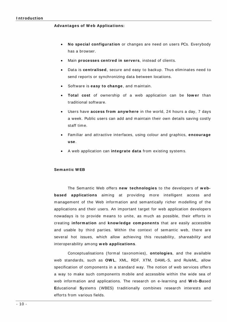
Advantages of Web Applications:
• No special configuration or changes are need on users PCs. Everybody
has a browser.
• Main processes centred in servers, instead of clients.
• Data is centralised, secure and easy to backup. Thus eliminates need to
send reports or synchronizing data between locations.
• Software is easy to change, and maintain.
• Total cost of ownership of a web application can be lower than
traditional software.
• Users have access from anywhere in the world, 24 hours a day, 7 days
a week. Public users can add and maintain their own details saving costly
staff time.
• Familiar and attractive interfaces, using colour and graphics, encourage
use.
• A web application can integrate data from existing systems.
Semantic WEB
The Semantic Web offers new technologies to the developers of web-
based applications aiming at providing more intelligent access and
management of the Web information and semantically richer modelling of the
applications and their users. An important target for web application developers
nowadays is to provide means to unite, as much as possible, their efforts in
creating information and knowledge components that are easily accessible
and usable by third parties. Within the context of semantic web, there are
several hot issues, which allow achieving this reusability, shareability and
interoperability among web applications.
Conceptualisations (formal taxonomies), ontologies, and the available
web standards, such as OWL, XML, RDF, XTM, DAML-S, and RuleML, allow
specification of components in a standard way. The notion of web services offers
a way to make such components mobile and accessible within the wide sea of
web information and applications. The research on e-learning and Web-Based
Educational Systems (WBES) traditionally combines research interests and
efforts from various fields.
Scientific and Technological Context
- 11 -
In this context, it was more than obvious to make the development
has a web application (instead of a standalone application, for example).
1.2.2 OVERVIEW OF ONTOLOGIES FOR INFORMATION SYSTEMS: WHY
USE ONTOLOGIES?
Knowledge representation is a central problem for the EO-KES-B project.
The main question is how can we store and manipulate knowledge in a formal
way so that it may be used to extract information out of data and to support
users in the identification of the appropriate products for their applications.
There are a number of approaches and paradigms to these questions and some
had been already tested and prototyped in the EO-KES-B project.
In the computer science community the term ontology has a more
constrained meaning, connected with knowledge sharing and reuse. Gruber
speaks of “an explicit specification of a conceptualisation”. Others might be more
specific, for example requiring the conceptualisation to be formal and shared or
as Guarino[] puts it “a logical theory accounting for the intended meaning of a
formal vocabulary, i.e. its ontological commitment to a particular
conceptualisation of the world”.
An ontology is similar to a dictionary or glossary, but with greater detail
and structure that enables computers to process its content. It consists of a set
of concepts, axioms, and relationships that describe a domain of interest. The
simplest form of an ontology is a taxonomy. However, ontologies do not define a
simple set of keywords: they structure the information. With structured
information it is possible to use ontologies for:
• consistency checking: if ontologies contain information about properties
and value restrictions on the properties, then type checking can be done within
applications;
• to provide completion: an application may obtain a small amount of
information from a user, such as the fact that she is looking for a high-resolution
screen on a pc, and then have the ontology expand the exact pixel range that is
to be expected; or it can be adaptive;
• to provide interoperability support: we may have a complete operational
definition for how one term relates to another term and thus, we can use

Introduction
- 12 -
equality axioms or mappings to express one term precisely in terms of another
and thereby support more “intelligent” interoperability;
• to support validation and verification testing of data (and schemas): if
an ontology contains class descriptions, these definitions may be used as queries
to databases to discover what kind of coverage currently exists in datasets ;
• to support structured, comparative, and customized search: if an
ontology contains mark-up information it can be used to prune comparative
searches and to point which properties are most useful to present in comparative
analyses so that users may have concise descriptions of the products instead of
comparisons in complete detail;
• to exploit generalization/specialization information. If a search
application finds that a user’s query generates too many answers, one may
dissect the query to see if any terms in it appear in an ontology, and if so, then
the search application may suggest specializing that term.
The above list is not exhaustive and its purpose is only the illustration of
some ways that ontologies have been used to support intelligent applications.
The use of ontologies greatly surpasses the simple use of keywords, due to
the structured and adaptive information representation supported by an
ontology. Moreover, ontologies allow the comparison and inference of conformed
knowledge based on other ontologies, providing the means to global, transparent
information sharing.
There are some issues with using interchangeably the terms ontology and
knowledge base. A knowledge base is an informal term for a collection of
information that includes an ontology as one component. Besides an ontology, a
knowledge base may contain information specified in a declarative language
such as logic or expert-system rules, but it may also include unstructured or
unformalized information expressed in natural language or procedural code.
A knowledge base should provide sufficient expressive power to represent
human knowledge as well as an efficient, powerful, and understandable
reasoning mechanism.

Internship Goals
- 13 -
1.3 INTERNSHIP GOALS
The main tasks were:
1. State of the art: In this task the available technologies were considered
and evaluated (see state of the art – section ) in order to fulfil the project
needs and to be used in the project development.
2. System architecture definition: The major part of system architecture
was already defined, although the selected tools imposed slightly
changes, related to the used technologies.
3. Knowledge Representation: at the beginning of this final degree
project, it was already defined the use of an ontology to represent
knowledge, and ontology itself was already structured. However, some
modifications had to be done. Initial ontology had to include the concept
of “Product Features” (what can be extracted from a product). Another
change was the insertion of the “Relation” concept, which relates two
ontology objects, with a specific domain, with a weight associated (more
on this later).
4. Search engine – The search procedure was defined in order to take
advantage of ontology engine (see Figure 28). A user should be able to
reach ontology concepts and instances, or even get direct access to the
products more related with his query search.
5. Graphic User Interface definition having in mind the need to be user-
friendly: intuitive and simple to learn and to use. This “presentation
layer” was developed specially with JSPs, which define the layout and call
the “logic layer” (Java packages).
6. Implementation was done in what we may call two layers:
a. Logic Layer – programmed in simple Java packages, in this layer
is defined an API to connect to Protégé and manipulate its objects
(section 4.3.1.3); another to WordNET (section 4.3.1.7); the
search algorithm which finds products associated with some
Protégé object; database connections interface; and some other
methods called by the presentation layer.
b. Presentation layer – The user interface, developed using JSPs.

Introduction
- 14 -
7. Evaluation tests – Each of the technologies used was first tested with
some web applications using it, assuring it was possible to use it in
development. Then, along the programming phase, the application had
been tested, as well as the integrity of data (see section 4.3.1.2).
1.4 REPORT STRUCTURE
An overall description of the main sections is given below:
1. Introduction: Shows the academic, the scientific and technological
context of the project. Gives an overview of the project and its
architecture.
2. Application Survey: Brief description of the technologies used in the
development.
3. Knowledge Representation: First part describes the use of an
ontology to represent knowledge – the motive and the design. In the
second part is explained the idea of user adaptation.
4. Development: Describes the steps made in the application
development. Is divided in 3 phases:
1. Framework installation and configuration;
2. Beginning of the implementation, testing the
technologies to be used;
3. The core of the development, connecting the previous
development (different technologies) into a single
standalone web application.
5. Application Presentation: Explains the navigation throw the
ontology and shows a demonstration of a possible scenario in the
implemented application (a guided tour);
6. Conclusions: Includes an evaluation of the development and the
internship, and some notes about work be done in future, in the
project.
7. Bibliography: Information sources used as support for the
development of this report and project;
8. Annexes: Auxiliary information.
EO-KES-B Overview
- 15 -
1.5 EO-KES-B OVERVIEW
1.5.1 GLOBAL DESCRIPTION
The EO-KES project deals with the artificial and (semi-) automatic reproduction
(in an Earth Observation oriented domain) of several of the following human being
capabilities and processes: knowledge capture; knowledge reception; knowledge
archive; knowledge retrieval; knowledge organization; and knowledge application.
Hence, the 'services' (i.e., the transformations) provided and/or supported by the EO-
KES system are referred to as 'Knowledge Enabled' ones.
Our goal is to develop:
• Specific 'knowledge access' interfaces - thus assuming that it shall be feasible
to standardize knowledge formalization. De-facto standards to represent wide
types of knowledge are now available, from rule and complex ontology to
neural networks.
• 'Knowledge services', categorized as general purpose to grant the effective
handling of the knowledge.
• 'Domain Knowledge Enabled Services', which are those applications specific
constructed with all the general purpose available services (data, information
and knowledge ones).
• 'Applications: knowledge exploitation and formalization'. Resulting from the
combination of knowledge services as well as applications, which allow the
system to be 'instructed', support (supervised/unsupervised) learning or - in
general - bring knowledge into the system.
• 'HMI knowledge formalization and application'.
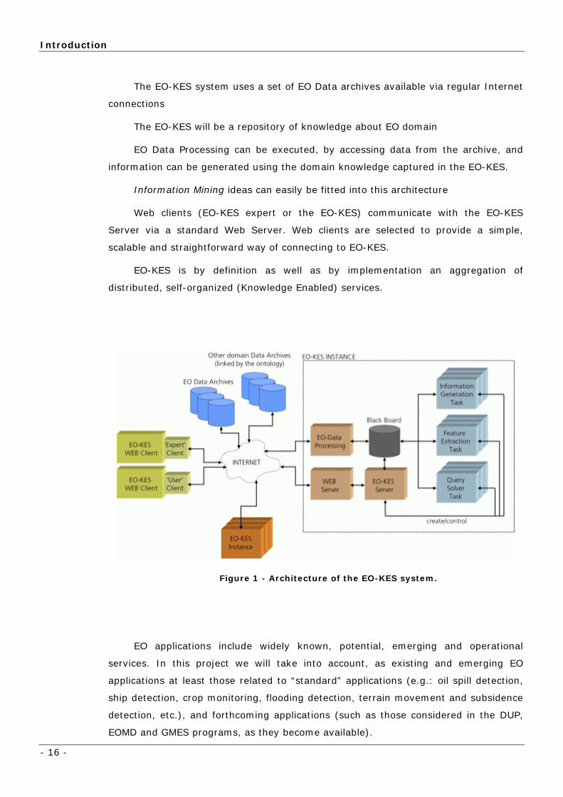
Figure 1 depicts the architecture of the EO-KES system, which most relevant
aspects are:
Introduction
- 16 -
The EO-KES system uses a set of EO Data archives available via regular Internet
connections
The EO-KES will be a repository of knowledge about EO domain
EO Data Processing can be executed, by accessing data from the archive, and
information can be generated using the domain knowledge captured in the EO-KES.
Information Mining ideas can easily be fitted into this architecture
Web clients (EO-KES expert or the EO-KES) communicate with the EO-KES
Server via a standard Web Server. Web clients are selected to provide a simple,
scalable and straightforward way of connecting to EO-KES.
EO-KES is by definition as well as by implementation an aggregation of
distributed, self-organized (Knowledge Enabled) services.
Figure 1 - Architecture of the EO-KES system.
EO applications include widely known, potential, emerging and operational
services. In this project we will take into account, as existing and emerging EO
applications at least those related to “standard” applications (e.g.: oil spill detection,
ship detection, crop monitoring, flooding detection, terrain movement and subsidence
detection, etc.), and forthcoming applications (such as those considered in the DUP,
EOMD and GMES programs, as they become available).

EO-KES-B Overview
- 17 -
The complexity of this project deserves a careful analysis about the approach
during its analysis, design, and prototyping phases. The first point of reference is
domain. Domain is – obviously – Earth Observation; nevertheless, a number of
‘concretions/focalisations’ are introduced. The following figure illustrates this
progressive focalisation and represents the origin of the ‘scale’ factor, which makes
the project ‘affordable’. Domain is a very relevant concept in this proposal, since it
defines the boundaries of the ‘ontology’ (the knowledge of the experts has to be
formalized).
Figure 2 - Progressive focalisation of the project’s domain.
The project is oriented in accordance with the limits of the domain. In the first
view, we consider a relevant contribution of EO domain experts directly supported by
Knowledge Engineers. It is our comprehension that the very essential goal of this first
‘phase’ is to structure the problem: i.e., the basis of the domain ontology. In order to
be in the position to match this goal, the proposal includes EO Specialists and
Knowledge Engineers.
The second view refers to EO-KES. EO-KES represents a sub-set of
functionalities, particularly those related to Knowledge Systems (Knowledge Enables
Services). At that point, major contributions shall be expected from Knowledge and
Software Engineers: How to gather, discover, formalize and use ‘that’ particular
knowledge? And how to implement all these?

Introduction
- 18 -
The third view is centred in the EO-KES Prototype. The EO-KES Prototype is –
once again – a subset, a representative subset, of the functionalities designed for the
EO-KES. Implementation, testing and validation are the core issues.
1.5.2 GLOBAL ARCHITECTURE
1.5.2.1 OVERVIEW
The overall Semantic Server design can be described by the following figure:
KnowledgeKnowledge BaseBase OntologyOntology
OWLFile
RDF/XML-ABBREVFile Format
Java API
Console
Semantic ServerSemantic Server
ASCIIText
UserUser
UNINOVAUNINOVA
WordNet
Lexical analysisLexical analysisEOKES-B
Application(Java JAR)
Protégé
WordNet
DictionaryDictionary BaseBase
WordNet File
LexicographerFile Format
HMIHMI
Java API
Pro
teg
eA
PI
Wo
rdN
etA
PI
Figure 3 - Specific Semantic Server current architecture.
The main components of the system are the Ontology, the Lexical Analysis component
(provided by WordNET) and the EO-KES application. User interaction is currently provided
via a console, which allows the user to query the system and obtain the relevant results.
The ontology is implemented in Protégé, a tool that allows the construction of ontologies
and knowledge bases and interaction with them. The codification of the knowledge is made
through the use of the OWL language. OWL is considered the future global language to
represent normalized knowledge and to assure a satisfactory response (instantaneous
performance). To accommodate the expected system growth, a database will replace the file
system, but the OWL language will still be the used language to communicate with it. The
knowledge is stored in persistent formats using OWL encapsulated in XML and saved in the
RDF/XML – ABBREV files format.
The Lexical Analysis component development of the WordNetAPI (Section 4.3.1.7) and
ProtegeAPI (section 4.3.1.3) libraries was done in order to isolate those modules from the
rest of the application algorithm.
EO-KES-B Overview
- 19 -
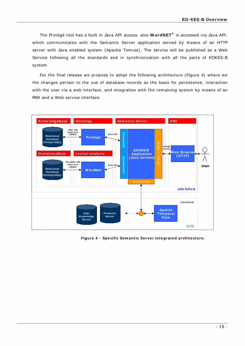
The Protégé tool has a built in Java API access, also WordNET® is accessed via Java API,
which communicates with the Semantic Server application served by means of an HTTP
server with Java enabled system (Apache Tomcat). The service will be published as a Web
Service following all the standards and in synchronization with all the parts of EOKES-B
system.
For the final release we propose to adopt the following architecture (Figure 4) where we
the changes pertain to the use of database records as the basis for persistence, interaction
with the user via a web interface, and integration with the remaining system by means of an
RMI and a Web service interface.
Knowledge Knowledge Base Base Ontology Ontology
Java API
Web Browser (HTTP)
Semantic ServerSemantic Server
XHTML(HTTP)
UserUser
User Knowledge
Server User
Knowledge Server
Products Server
Products Server
UNINOVA UNINOVA
GTD GTD
WordNet
Lexical analysisLexical analysisEOKES-B
Application(Java Servlet)
Protégé
WordNet
Dictionary Dictionary Base Base WordNet DB
back-end (JDBC)
(Simplified)
Pro
teg
eA
PI
Word
NetA
PI
HMI HMI
Java API
SpatialTemporal
Data
Web Service
OWL DB back-end (JDBC)
Relational Database
(PostgreSQL) Relational Database
(PostgreSQL)
Relational Database
(PostgreSQL) Relational Database
(PostgreSQL)
Ap
ach
e +
Tom
cat
Figure 4 - Specific Semantic Server integrated architecture.

Application Survey
- 20 -
2 Application Survey
use of several
technologies (some of them very recent and still in development).
This section gives a brief description of these technologies.
2.1 PROTÉGÉ
architecture for the creation of customized knowledge-based tools.
Moreover, Protégé is a tool, which allows the user to:
• Construct a domain ontology;
• Customize knowledge-acquisition forms;
• Enter domain knowledge.
As shown in the previous section, the application evolves the
PPrroottééggéé [10] is an integrated tool for ontology and knowledge base
editing. Protégé-2000 is also an open-source, Java-based, extensible
Protégé has been selected due to a number of characteristics, like being
java-based, open-source, and extensible. Stanford Medical Informatics at the
Stanford University School of Medicine developed protégé-2000 with support
from the National Library of Medicine, the National Science Foundation, and the
Defence Advanced Research Projects Agency.

WordNET
- 21 -
Figure 5 - Protégé
Protégé was used to “build” the ontology:
• Design: concepts, and relations between them;
• Population: the data – instances of concepts, and relations between
them.
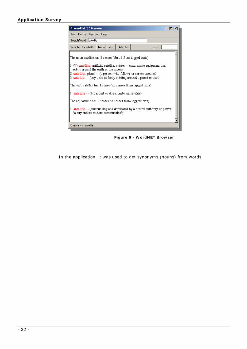
2.2 WORDNET
WordNET® [8] is an online lexical reference system whose design is
inspired by current psycholinguistic theories of human lexical memory. English
nouns, verbs, adjectives and adverbs are organized into synonym sets, each
representing one underlying lexical concept. Different relations link the synonym
sets.
The Cognitive Science Laboratory at Princeton University developed WordNET
under the direction of Professor George A. Miller (Principal Investigator).
Application Survey
- 22 -
Figure 6 - WordNET Browser
In the application, it was used to get synonyms (nouns) from words.
Eclipse
- 23 -
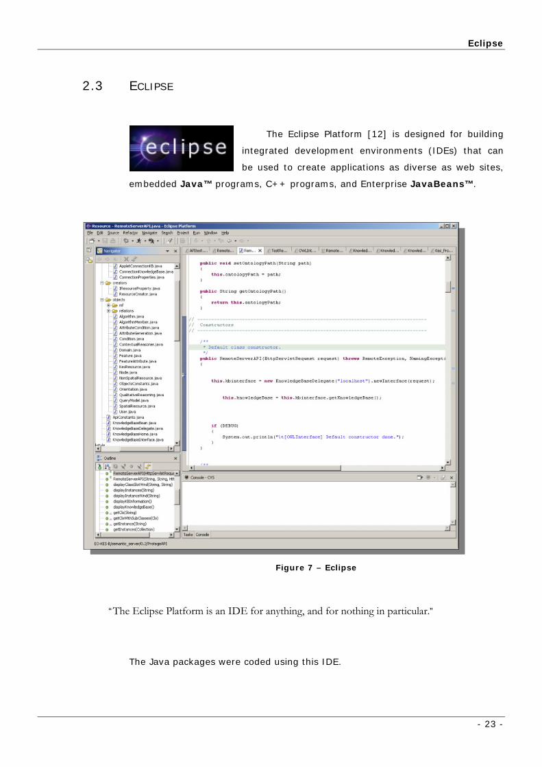
2.3 ECLIPSE
The Eclipse Platform [12] is designed for building
integrated development environments (IDEs) that can
be used to create applications as diverse as web sites,
embedded Java™ programs, C++ programs, and Enterprise JavaBeans™.
Figure 7 – Eclipse
“The Eclipse Platform is an IDE for anything, and for nothing in particular.”
The Java packages were coded using this IDE.
Application Survey
- 24 -
2.4 TOMCAT
Tomcat [3] is the servlet container that is used in the official
Reference Implementation for the Java Servlet and
JavaServer Pages technologies. The Java Servlet and JSPs
specifications are developed by Sun under the Java
Community Process.
Tomcat is developed in an open and participatory environment and released
under the Apache Software License. Tomcat is intended to be a collaboration of
the best-of-breed developers from around the world.
This was the server used to run the application: it’s easy to configure, easy to
use and it’s free.
2.5 JAVASERVER PAGES TECHNOLOGY
JavaServer Pages (JSP) technology [4] enables Web
developers and designers to rapidly develop and easily maintain,
information-rich, dynamic Web pages that leverage existing
business systems. As part of the Java technology family, JSP technology
enables rapid development of Web-based applications that are platform
independent. JSP technology separates the user interface from content
generation, enabling designers to change the overall page layout without altering
the underlying dynamic content.
JavaServer Pages (JSPs) were used to design the web interface, while they
call the core of the application, developed in a Java package (section 4.3).

JavaServer Pages Technology
- 25 -
2.5.1 JSP TECHNOLOGY AND JAVA SERVLETS
JSP technology uses XML-like tags that encapsulate the logic that
generates the content for the page. The application logic can reside in server-
based resources (such as JavaBeans component architecture) that the page
accesses with these tags. Any and all formatting (HTML or XML) tags are
passed directly back to the response page. By separating the page logic from its
design and display and supporting a reusable component-based design, JSP
technology makes it faster and easier than ever to build Web-based
applications.
JavaServer Pages technology is an extension of the Java Servlet
technology. Servlets are platform-independent, server-side modules that fit
seamlessly into a Web server framework and can be used to extend the
capabilities of a Web server with minimal overhead, maintenance, and support.
Unlike other scripting languages, servlets involve no platform-specific
consideration or modifications; they are application components that are
downloaded, on demand, to the part of the system that needs them. Together,
JSP technology and servlets provide an attractive alternative to other types of
dynamic Web scripting/programming by offering:
• Platform independence;
• Enhanced performance;
• Separation of logic from display;
• Ease of administration;
• Extensibility into the enterprise;
• And, most importantly, ease of use.

Application Survey
- 26 -
Today servlets are a popular choice for building interactive Web
applications. Third-party servlet containers are available for Apache Web
Server, Microsoft IIS, and others. Servlet containers are usually a component
of Web and application servers, such as BEA WebLogic Application Server,
IBM WebSphere, Sun Java System Web Server, Sun Java System
Application Server, and others.
2.5.2 COMMUNITY BACKGROUND
The JSP specification is the product of industry-wide collaboration with
industry leaders in the enterprise software and tools markets, led by Sun
Microsystems. Sun has made the JSP specification freely available to the
developer community, with the goal that every Web server and application
server will support the JSP interface. JSP pages share the "Write Once, Run
Anywhere" advantages of Java technology. JSP technology is a key component
in the Java 2 Platform, Enterprise Edition, Sun's highly scalable architecture
for enterprise applications.

- 27 -
3 Knowledge Representation
3.1 AN ONTOLOGY-AIDED APPROACH TO EO PRODUCT SEARCH
3.1.1 A DESIGN PATTERN FOR ONTOLOGY DESIGN
ect an oil-spill and suggests that product from an input query of simply
“oil-spill”.
ring methodologies and the discovery of templates for knowledge intensive
tasks.
One of the main concerns in using an ontology in KES-B is to improve the
capabilities of EO product search. The query system will use some user domain
ontology and an EO domain ontology to initially perform query completion (by
supplying additional associated terms, query expansion (by adding associated terms
to the initial ones). After settling in a set of terms to search and potentially a set of
derived queries, the search process uses the ontology to infer relationships between
concepts, for instance when using the captured relation that a SAR image can be
used to det
Before tackling the issue of how to use an ontology to improve the search
process we must first consider the task of modelling expert knowledge and build the
starting ontology. The experience of conducting knowledge engineering has
demonstrated the need for a structured approach to it, one that attempts to find
opportunities for modularity and reuse, discarding the view of a set of rules as
structured by simply assuming rules as modular in themselves. The broad design
principle is well demonstrated by the appearance of established knowledge
enginee
A design pattern for structuring a knowledge base, inspired in Gruber’s design
principles is helpful in guiding us through the rationale of the KES-B ontology. In this
design pattern, a start-up generic KB contains all the constructs we use to build an
ontology (e.g. some kind of class mechanism with formal is-a relations, a generic
relation, time, space, etc). This part is composed of a state dependent part (“core”

Knowledge Representation
- 28 -
KB) and a state-independent part (generic ontology). The generic ontology is called
meta-ontology or top-level ontology in other design patterns. Top-level ontologies
are currently the focus of several proposals to adopt a specific top-level ontology as
a standard, in the expectation that this will promote wider knowledge sharing and
reuse (e.g. the CyC project [5, 6]). These are the building blocks in which a domain
expert can express a particular domain ontology. As shown in Figure 8, the generic
KB n this example, shared by scientists from completely different domains. is, i
Figure 8 - A design pattern for ontology design using Gruber's design principles.
ously connected to
a spe
cific ontology for the information system (in our case KES-B)
supporting the search.
The domain KB contains essentially a set of domain ontologies. Each domain
ontology is shared inside a group of scientists and is designed to be reusable outside
a specific information system. This materializes a true-shared conceptualisation and
provides the most important knowledge for improving a search procedure over
simple keyword search. Finally, application-tied concepts are maintained in the
application KB, which is the least reusable component, and is obvi
cific information system’s goal and respective data sources.
This design pattern is not without its issues, since we are not presenting here
the existence of intra-domain relations. These are important since they allow us to
navigate from a specific user domain ontology to the EO domain ontology to find
relevant products. Nevertheless this discussion is important for us to conclude on
the needed components for an ontology-aided EO product search: a generic
ontology with the base concepts; a concrete user domain ontology and an EO
domain ontology; a spe
An ontology-aided approach to EO product search
- 29 -
In the KES-B project, the following two user domains were selected: water
quality (with oil-spill and algae bloom detection) and maritime security (with ship
detection and winds & waves information). This totals four different case studies,
however due to the tight connection between the selected areas, a single domain
ontology can capture the most important concepts of the two domains. In fact, they
were selected because a small set of EO product types are used in all of them.
3.1.2 INFORMATION SEARCH IN KES-B: THE GAP FROM USER
DOMAIN TO EO DOMAIN
One of the main goals of the KES-B system is how to help a user, familiar or
unfamiliar with EO products to find relevant EO products. In this section we provide
some insights about how to bridge the gap between user domain and EO domain.
To use EO products (e.g. a SAR (Synthetic Aperture Radar) image or a photo in
the visible spectrum range) for a concrete problem is far from a trivial issue of
acquiring EO data at a distributor. The final-user, in most cases, needs a processed
product and never the original base EO product. For example, to detect an oil-spill a
SAR image must be used to pinpoint a potential oil-spill area. Additional data about
winds and waves is required and only after merging all the products (the SAR image
and the winds and waves data) and with some expert assistance can the oil-spill be
identified with a reasonable accuracy. Therefore, if a user has no expertise in EO
terminology and available products just the initial task of searching for relevant
products is considerably challenging.
To summarize this, a useful way of thinking about the problematic of EO
product search is structured in the next figure:

Knowledge Representation
- 30 -
User Domain
EO Domain
EO Products
Query stated in user domain terminology
Knowledge of EO product
usage
EO product features
Are there any useful EO
products for my problem?
?
Knowledge Engineering of the user domain (e.g. basic domain ontology,
some inference knowledge about specific problems)
Model EO concepts (e.g. instrument, product) and what parameters are
observable in a specific EO product
Simple modelling of all EO products technical features and other attributes
Model quantities/events/objects that need observation in the user domain
Knowledge formalisation
User Domain
EO Domain
EO Products
Query stated in user domain terminology
Knowledge of EO product
usage
EO product features
Are there any useful EO
products for my problem?
Query stated in user domain terminology
Knowledge of EO product
usage
EO product features
Are there any useful EO
products for my problem?
??
Knowledge Engineering of the user domain (e.g. basic domain ontology,
some inference knowledge about specific problems)
Model EO concepts (e.g. instrument, product) and what parameters are
observable in a specific EO product
Simple modelling of all EO products technical features and other attributes
Model quantities/events/objects that need observation in the user domain
Knowledge formalisation
Figure 9 - Knowledge Formalisation
An initial query, stated in some user domain terminology, with no a priori
connection to EO domain, must be somehow “translated” into associated EO
products that were the target of a focused product search. Note how our
proposal suggests overcoming the knowledge gap using knowledge of user
domain and EO domain semantics, available after explicit knowledge
formalisation. Moreover, some inference knowledge may also be needed, for
instance when modelling the consequences to natural resources of an oil-spill.
This knowledge is used afterwards to make inferences about the input query and
find associated concepts that indirectly connect the user query to EO products.
Other approaches attempt to induce terms and relations between them using a
corpus of documents. However several factors influenced our decision of a
classical knowledge engineering approach:
• Clear requirement/goal of developing a collaborative environment where
experts and non-user experts can share their knowledge over time;
• Facilitating agreement on terminology for EO product usage;
• Support for users with no previous exposure to EO terminology;
• Lack of a representative corpus of EO documents to use.
Summary of some of the fundamental benefits for the KES-B project of an
ontology-based solution:
• The structure provided by explicit knowledge formalization techniques is
beneficial in many tasks (e.g. consider system engineering and the generic
product generation solutions made possible)

An ontology-aided approach to EO product search
- 31 -
• A caveat is the simple fact that EO products are not text documents. It
is not straightforward to get extract keywords directly, unless we decide to
attach a pre-fixed keywords (in many cases manually) to an EO product, which is
a more limited option. Image Information Mining methods are now capable of
extracting several types of objects from an image but are not capable of
providing it’s semantic.
• The possibility of explaining why a product might be interesting to a
user.
• Adaptation of the search and navigation to the user profile depending
on their number of accesses. The occurrences are measured and used to provide
a type of learning ability to the Ontology query system (what we called user-
adaptation process, later explained).
3.1.3 GENERIC ONTOLOGY
The ontology design has been made using the Protégé 2000 knowledge editor
[10], so several mechanisms available in Protégé such as class inheritance,
restrictions are used as standard tools and are not mentioned in the model.
The generic part we need to develop is actually very small, since we are
relying on Protégé structure (which provides most of the generic ontology). We
only need to model two things. One is a way to associate every concept to a
user/domain pair. This is because KES-B is multi-user and multi-domain and
there are many intricacies in the way users can be in several domains, concepts
can have different meanings in different domains and how to allow some level of
user-specific modifications. The second is the notion of relation itself, so a
domain ontology can be created with relations.
For the first one, and as we will review again in section 3.2.2, all concepts
are associated with pairs of user/domain, relating each user to a specific domain,
for each concept, as represented in Figure 10:

Knowledge Representation
- 32 -
Figure 10 - Relation between an object and user/domain.
Now this logical picture need be implemented directly in the ontology, and as
we shall see in section 4.2, we can implement it in different ways. This works as
a domain annotated semantic graph. Note an important subtlety, some concepts
in KES-B ontology can and will belong to several domains (e.g. an Environmental
Event can be of interest to a generic EO domain or to a specific group of people
interested in oil-spills).
The ontology will be presented using UML diagrams like the one below:
Figure 11 - An ontology UML example diagram.
In Figure 11 the connections between classes (including the ones represented by curves)
are regular UML association classes so they are separate objects, as well. They represent
some of relation between another two objects, linked to a specific domain. The strength of

An ontology-aided approach to EO product search
- 33 -
this relation is measured in its attribute weight. This leads us to the definition of the KES-B
Relation class as seen in Figure 12.
Figure 12 - KES-B Relation Diagram
The objects related, using a KES-B Relation, are attributes of this class. With
this representation, it is possible to have users in several domains.
Some relations used in KES-B ontology are represented in Figure 13:
Figure 13 - KES-B Relations Hierarchy.
Each relation in the model is a sub-class of KES-B Relation, deriving its attributes.
Figure 14 shows more in detail how a KES-B relation is defined in Protégé:

Knowledge Representation
- 34 -
Figure 14 – KES-B Relation in Protégé.
As shown in Figure 12, weight is an integer, representing the relation strength.
Knowledge Domain is an object of the class KES-B Knowledge Domain (it may be
EO Application Domain, EO Domain or EO Science Domain – with the possibility
of creating any other domains derived from the same class). The attributes to and
from are instances of any objects of the class diagram – they represent the objects
associated by the KES-B Relation.
The main relations of the ontology, connecting the major concepts (EO Event,
Product and EO Product), will be used in searches more often than the others:
Caused By, Related With, Analysed From, Detected In and Extractable From.
Relations like Has are one-way, and one of the objects related acts like an attribute of
the other.
An ontology-aided approach to EO product search
- 35 -
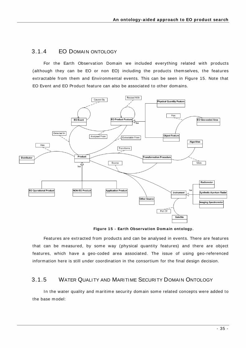
3.1.4 EO DOMAIN ONTOLOGY
For the Earth Observation Domain we included everything related with products
(although they can be EO or non EO) including the products themselves, the features
extractable from them and Environmental events. This can be seen in Figure 15. Note that
EO Event and EO Product feature can also be associated to other domains.
Figure 15 - Earth Observation Domain ontology.
Features are extracted from products and can be analysed in events. There are features
that can be measured, by some way (physical quantity features) and there are object
features, which have a geo-coded area associated. The issue of using geo-referenced
information here is still under coordination in the consortium for the final design decision.
3.1.5 WATER QUALITY AND MARITIME SECURITY DOMAIN ONTOLOGY
In the water quality and maritime security domain some related concepts were added to
the base model:

Knowledge Representation
- 36 -
Figure 16 - Water Quality and Maritime Security Domain Model.
Both of these domain ontologies are subsumed by the generic concepts.
The implementation of them is equivalent to insert instances of Feature, Event,
etc and linking them to the respective domain.
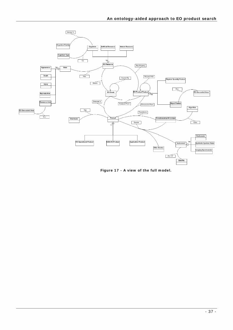
3.1.6 THE COMPLETE MODEL: KES-B ONTOLOGY GUIDED TOUR
The full model is presented below using an object-oriented notation. Using
an UML diagram to present it is misleading in some details (e.g. the user/domain
associations are not shown) but we place it here since it helps considerably in
giving a broad view of the model.
In addition, considering the complexity of such model since relations are
also objects (as seen in previous section), we had to opt for some design
considerations. The curved lines are our relations in the ontology. We are only
describing classes and their names in this object-oriented model, so the concrete
instances and their relations with other instances are not shown. In a sense we
are providing a partial view of the full ontology that only contains the essential
concepts and structure.
An ontology-aided approach to EO product search
- 37 -
Figure 17 - A view of the full model.

Knowledge Representation
- 38 -
This ontology is implemented in Protégé using the following class hierarchy:
Figure 18 – Protégé Classes Diagram.
Concepts here are represented as classes. In this model, the relations
between particular objects are not visible, because they are represented by
creating instances of KES-B Relations. Next we provide a small guided tour
that summarized the all model. To facilitate the model description the notation
used is: concepts in bold and relations with underscore.
Reading the model from the concept “Product” we can observe the
following main relations and concepts:

An ontology-aided approach to EO product search
- 39 -
A product can have three types of sources: it can be from an instrument
(part-of a satellite) or from a transformation procedure (when it is a product
originated by a specific algorithm) or from any other source. An instrument is
organized in three categories: radiometer, synthetic aperture radar and
imaging spectrometer. A product can be of four types: a transformed one
(transformation procedure transforms input products using algorithms); an
EO operational product; application products (e.g. oil-spill products, algae
bloom products and winds & waves products); and non-EO products. In
addition a product always has a data distributor.
The concept of EO product feature is related-with other features; it is
organized in physical quantity features or object features and it is
extracted-from product. In addition, object features have an EO geo-coded
area associated with it.
An EO event (e.g. oil spill, dead-fish) affects an EO resource, is analysed-
from EO product features, is detected-in product and an EO event can also
be caused-by other EO events. Each resource has a set of states that can be
altered by the occurrence of an event, which are: appearance e.g. the colour
of the water; death e.g. dead fish; injury e.g. some algae may cause injuries in
the skin of some fish; reproduction e.g. increase in fish stocks; and the
resource area is given by the EO geo-coded area.
An EO resource also has-property, denoted as EO product-features (e.g.
ocean colour, chlorophyll). The EO resources are organized in three
categories: Organism, Artificial Resource and Natural Resource. The
Organism is of a specific type (algae, animalia, fungi or plantae) and belongs to
an organism family, e.g., the algae can be of the rhodophyta family. The
Natural resources category can include water, land and atmospheric resources,
such as rivers and oceans. The Artificial resources category contains all other
resources that are “man-tempered”.
3.1.7 STRONG RELATION: STATE - EO RESOURCE – EO EVENT
During the development of the web application it become necessary to
emphasise the strength of the relation between a state and a resource, like
“dead” and “fish”, for instance, which was affected by an event, like “oil spill”. In
order to know directly what state-resource was affected by determined event,

Knowledge Representation
- 40 -
ontology was updated with a new relation, which relates the relation between
State and EO Resource with an EO Event, as shown in the figure below.
Figure 19 - Strong connection between State, EO Resource and EO Event.
USER ADAPTATION
- 41 -
3.2 USER ADAPTATION
3.2.1 WHY AND WHAT TO ADAPT?
The KES-B project provides a complex scenario of several groups of
cooperative researchers, each one belonging to a core domain, but possibly
assigned to multiple domains of interest. Users can be experts in a given
domain, in principle capable of participating in a domain ontology definition.
However, for the most part, they have some knowledge of their domains and
very little of the EO one.
The behaviour of a particular user or of a group of users is important
information since not all concepts and products are equally important. The
behaviour of a user is captured as a minimum in his query history, or in a more
advanced way in the overall activity when interacting with the system.
The goal of user adaptation is to use the user interaction historical data to
modulate the search process with the expectation of, after a large enough period
of time;
• improve query results: a better order of the output result set;
• helping infrequent users: a new user might benefit from the accumulated
interaction of a group of experts with the system as she is guided first to the
most used concepts and queried products.
3.2.2 USER-SPECIFIC ADAPTATION OF DOMAIN ONTOLOGY SEARCH
The directed graph structure of the ontology has an obvious choice a
weighted approach. The weights in a graph act as natural search heuristic and
can also be used to sort the final result set. The model presented here already
associates every relation with a domain. This association is given a weight and
by updating the weights using some learning algorithm and historical data it will
adapt the search over time. Some weights might be initially set to different
magnitudes, since some semantic relations are already known to be of higher
importance than others (e.g. connecting a feature of interest in a domain with a
product that contains it); nevertheless in most situations the weights have to be
adjusted using user data.

Knowledge Representation
- 42 -
The nodes also need a weight (consider weighting some products more
than others) than can be subjected to an update rule. When not activated, the
weight has a simple decay process.
Finally, interesting uses of using a weighted directed graph and adapt it to
user queries also under research include: conflating several users to get an
average of a domain; use the information about domain of other users to assign
a user to a domain
KES-B system design requirements for user adaptation
We shall distinguish between relation weights, or strengths associated to
the ontology graph, and product weights, meaning the weights associated with
each product in an ontology (object) node.
3.2.2.1 PRODUCT WEIGHTS
In terms of implementation, i.e. a layer below the ontology, a record of the
most searched “objects” is kept. The current design for the system associates
one record to each domain. Users have to login into the system choosing one
domain. One user may be allowed to login into different domains, but in each
login he will be under a single one. The system is prepared to be extended so
that for each user there is a specific record, which represents his preferences
according to previous interactions.
This record is used to define an order of preferences and can also be used
in the automatic selection of the final products. As an example of the current
implementation consider users under a certain domain usually searching
products from ENVISAT satellite. So, it makes sense that, when displaying
results, the first products appearing are from that satellite.
So, for each domain, we keep track of all products “activated” by users in
that domain, the weight of the product, computed taking into account the
number of times each product is activated, and the date a product was last
activated, as well.
USER ADAPTATION
- 43 -
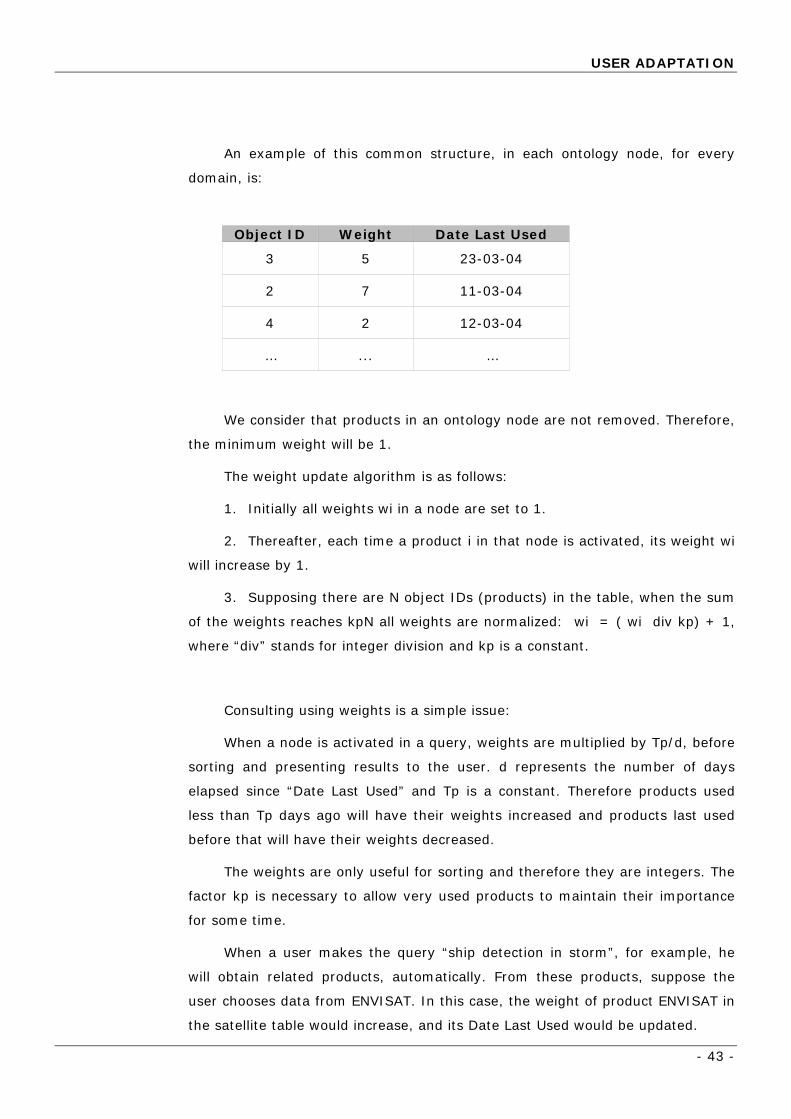
An example of this common structure, in each ontology node, for every
domain, is:
Object ID Weight Date Last Used
3 5 23-03-04
2 7 11-03-04
4 2 12-03-04
… ... …
We consider that products in an ontology node are not removed. Therefore,
the minimum weight will be 1.
The weight update algorithm is as follows:
1. Initially all weights wi in a node are set to 1.
2. Thereafter, each time a product i in that node is activated, its weight wi
will increase by 1.
3. Supposing there are N object IDs (products) in the table, when the sum
of the weights reaches kpN all weights are normalized: wi = ( wi div kp) + 1,
where “div” stands for integer division and kp is a constant.
Consulting using weights is a simple issue:
When a node is activated in a query, weights are multiplied by Tp/d, before
sorting and presenting results to the user. d represents the number of days
elapsed since “Date Last Used” and Tp is a constant. Therefore products used
less than Tp days ago will have their weights increased and products last used
before that will have their weights decreased.
The weights are only useful for sorting and therefore they are integers. The
factor kp is necessary to allow very used products to maintain their importance
for some time.
When a user makes the query “ship detection in storm”, for example, he
will obtain related products, automatically. From these products, suppose the
user chooses data from ENVISAT. In this case, the weight of product ENVISAT in
the satellite table would increase, and its Date Last Used would be updated.

Knowledge Representation
- 44 -
3.2.2.2 RELATION WEIGHTS
For relation weights in the ontology, we shall consider relations between
concepts and instances of concepts separately.
Concept relations
Considering the query just presented “ship detection in storm”, for
example, would increase weights of the ontology relation between “ship” and
“storm” in a similar way to the one defined above for product weights.
However, modifications in arc weights will be different for each direction of
the arc. Supposing an arc between nodes i and j, we will have Ni as the number
of arcs leaving I, and Nj the number of arcs leaving j. The weight update
algorithm is the same as above using Ni or Nj instead of N, with constants kc
and Tc.
This approach allows that the fact of an ontology node being activated may
produce answers including concepts (nodes) that are frequently related to the
ones used in the query. This may provide new and important information
helping the user to efficiently find answers to the problem he is approaching.
Instance relations
Adding to concept relations, the system also maintains relations between
instances of directly related concepts (concepts connected by an arc in the
ontology). This is accomplished by maintaining a structure similar to the one
depicted above for the relations of each instance with instances from a related
concept. For example “oil spill” is an instance of “Event” concept. Since “Event”
has an ontology relation with “Satellite” concept, “oil spill” will have relations to
all instances of “Satellite”, namely INTELSAT, ENVISAT, etc. Notice that each
instance will have one of these structures for each concept connected to its
node.
The adaptation algorithm is also the same as used for products, with
constants kr and Tr.
Computation of the weights may be done on-line as each user interacts
with the system or off-line after user logout. In the later case the session log of
user actions has to be recovered for the adaptation phase.
Typical constant values are: kp = kc = kr = 10 and Tp = Tc = Tr = 10.
A final comment should be made on the complexity of the solution.
Adaptation as proposed here covers all types of objects and interactions. This

USER ADAPTATION
- 45 -
means that the number of weights will grow exponentially with increasing
knowledge in the system. Therefore a caveat emptor must be made about
scaling up the system, which may turn out to become quite large. However it
should also be noticed that in terms of computation the approach is light and can
be computed locally, thus with little influence in computing time.

Development
- 46 -
4 Development
This section describes the steps made in the development of the
application.
er choosing the technologies to use, they had to be
installed and configured.
some first tests to learn how to use them, and check their
behaviour.
the modifications that was causing, in order to adapt the
navigation to the user.
A more detailed description is shown below.
4.1 FIRST PHASE – FRAMEWORK CONFIGURATION/INSTALLATION
4.1.1 INSTALLING TOMCAT
In order to run JSPs, Tomcat server had to be installed.
Detailed installation procedures made:
install Tomcat, was
already installed, so, the following procedures were done:
1. he
DK release was installed: “C:\Program
Files\j2sdk1.4.2_01”;
In a first phase, aft
In a second phase, we started the development using those technologies
and making
In the last phase, using the knowledge and the developing of previous
phases, the technologies were connected and merged into a single web
application. All the logic procedures were developed in this phase. It was
designed the user interface where it was possible to search and navigate throw
an ontology, observing
Java Development Kit (JDK), from necessary to
Environment variable JAVA_HOME was set to the pathname of t
directory into which the J

First phase – framework configuration/installation
- 47 -
2. Tomcat 5 Binary Distribution was downloaded from site
http://jakarta.apache.org/site/binindex.cgi, and unpacked into
“C:\jakarta-tomcat-5” folder. This folder has the symbolic name
“$CATALINA_HOME”.
The following directory structure is created:
Figure 20 - Tomcat Directories Tree
Main directories description:
conf - Server configuration files (including server.xml)
logs - Log and output files
webapps - Automatically loaded web applications(all
applications were deployed in this directory)
work - Temporary working directories for web applications
temp - Directory used by the JVM for temporary files
(java.io.tmpdir)
3. The name pc-pbpub.uninova.pt was designated to the used server,
after their network properties had been configured (Figure 21):

Development
- 48 -
Figure 21 - TCP/IP Properties
4. By default, a non-SSL HTTP/1.1 Connector is established on port 8080.
So, it was changed to port 80 (default port of HTTP), in file
“$CATALINA_HOME/conf/server.xml”:
<Connector port="80" maxThreads="150" minSpareThreads="25"
maxSpareThreads="75" enableLookups="false" redirectPort="8443"
acceptCount="100" debug="0" connectionTimeout="20000”
disableUploadTimeout="true" />
5. Tomcat 5 could then be started by running
“$CATALINA_HOME\bin\startup.bat” .
To shut down: “$CATALINA_HOME\bin\shutdown.bat”

First phase – framework configuration/installation
- 49 -
6. The default web
applications included
with Tomcat 5 are
available by visiting:
http://pc-
pbpub.uninova.pt
Figure 22 - Tomcat Index Page (Showing server is running)
7. Web applications could be managed online:
Figure 23 - Web Application Manager.

Development
- 50 -
4.2 SECOND PHASE
Before advancing to “real implementation” some technology testing had to
be made, first, to insure we were in the right track.
4.2.1 PROTÉGÉ WEB BROWSER
Functionality
The protégé browser [13] is a java based web application that allows users
to share their protégé ontologies over the Internet. The application is deployed
using an application server (like Tomcat). It provides the essential functionality
needed to browse a protégé knowledge base. It also provides functionality to
carry out text-based searches through the knowledgebase.
This made us understand the main procedures in the connection of
the user with a Protégé project, using a browser.
Second Phase
- 51 -
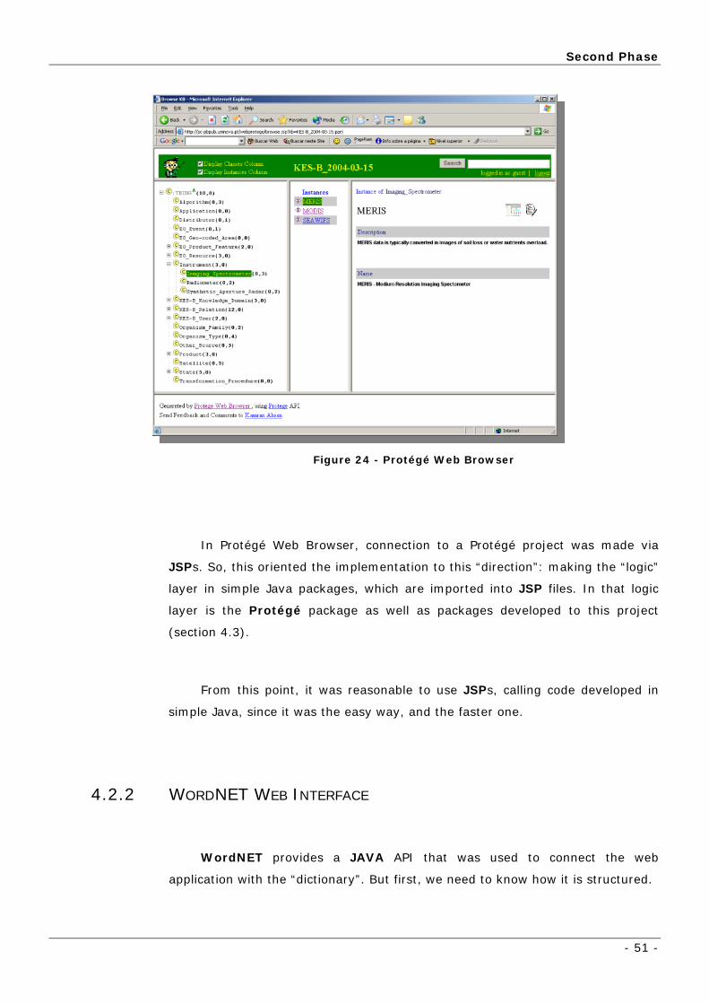
Figure 24 - Protégé Web Browser
In Protégé Web Browser, connection to a Protégé project was made via
JSPs. So, this oriented the implementation to this “direction”: making the “logic”
layer in simple Java packages, which are imported into JSP files. In that logic
layer is the Protégé package as well as packages developed to this project
(section 4.3).
From this point, it was reasonable to use JSPs, calling code developed in
simple Java, since it was the easy way, and the faster one.
4.2.2 WORDNET WEB INTERFACE
WordNET provides a JAVA API that was used to connect the web
application with the “dictionary”. But first, we need to know how it is structured.
Development
- 52 -
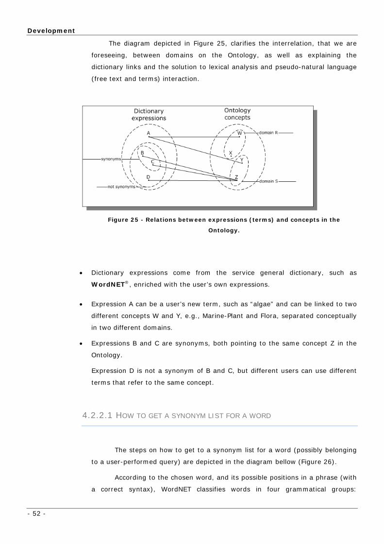
The diagram depicted in Figure 25, clarifies the interrelation, that we are
foreseeing, between domains on the Ontology, as well as explaining the
dictionary links and the solution to lexical analysis and pseudo-natural language
(free text and terms) interaction.
Figure 25 - Relations between expressions (terms) and concepts in the
Ontology.
• Dictionary expressions come from the service general dictionary, such as
WordNET®, enriched with the user’s own expressions.
• Expression A can be a user’s new term, such as “algae” and can be linked to two
different concepts W and Y, e.g., Marine-Plant and Flora, separated conceptually
in two different domains.
• Expressions B and C are synonyms, both pointing to the same concept Z in the
Ontology.
Expression D is not a synonym of B and C, but different users can use different
terms that refer to the same concept.
4.2.2.1 HOW TO GET A SYNONYM LIST FOR A WORD
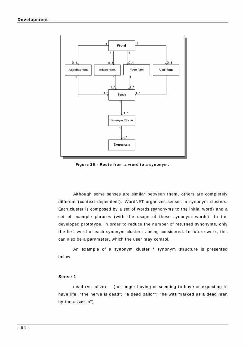
The steps on how to get to a synonym list for a word (possibly belonging
to a user-performed query) are depicted in the diagram bellow (Figure 26).
According to the chosen word, and its possible positions in a phrase (with
a correct syntax), WordNET classifies words in four grammatical groups:

Second Phase
- 53 -
adjectives, adverbs, noun or verbs. (As an example, the word “dead” can be
classified as a noun, adjective or an adverb). The current algorithm does not
perform any syntactic analysis on the role of the word on a given query so all
synonyms for all possible grammatical groups are procured and returned to the
user.
For each grammatical form, all senses are found (organized in “synset”
structures – refer to the WordNET annex for further information). (As an
example, the word “dead”, as a noun, has 21 senses associated to it). At the
present moment, users can restrict synonyms only to the “best” N senses.
WordNET internally organizes senses according to a relevance order.
When using the graphical WordNET application, senses are displayed according
this order, first the most relevant and then all other senses ordered by
decreasing relevance. In the developed prototype, instead of only returning a list
of synonyms to the user, a relevance factor for each synonym is also returned in
order to the user to determine “how good” the synonym is. The relevance factor
is as better, as smaller the relevance number. The most relevant word - entered
by the user – has a relevance factor equal to 1.
Development
- 54 -
Figure 26 - Route from a word to a synonym.
Although some senses are similar between them, others are completely
different (context dependent). WordNET organizes senses in synonym clusters.
Each cluster is composed by a set of words (synonyms to the initial word) and a
set of example phrases (with the usage of those synonym words). In the
developed prototype, in order to reduce the number of returned synonyms, only
the first word of each synonym cluster is being considered. In future work, this
can also be a parameter, which the user may control.
An example of a synonym cluster / synonym structure is presented
below:
Sense 1
dead (vs. alive) -- (no longer having or seeming to have or expecting to
have life; "the nerve is dead"; "a dead pallor"; "he was marked as a dead man
by the assassin")

Second Phase
- 55 -
=> breathless, inanimate, pulseless -- (appearing dead; not
breathing or having no perceptible pulse; "an inanimate body"; "pulseless and
dead")
=> bloodless, exsanguine, exsanguinous -- (destitute of blood
or apparently so; "the bloodless carcass of my Hector sold"- John Dryden)
=> cold -- (lacking the warmth of life; "cold in his grave")
4.2.2.2 HOW TO GET A LIST OF SYNONYM EXPRESSIONS FROM A
EXPRESSION
A synonym expression is constructed using the process described
previously, applying it to all words present in the query expression. The final
synonym expressions result from the permutation of all synonyms for each
individual word (but maintaining the word order). The textual synonym value
results from the concatenation of all synonyms, and the relevance of that
expression is calculated as the product of the relevance of each individual
synonym present in the expression.

Development
- 56 -
4.2.3 IMPLEMENTATION ARCHITECTURE:
For the first release of the prototype integration was devised using a Java
API already developed (open source) to connect the EOKES-B application to
WordNET®.
Java
EOKES - B Application
(Java JAR)
Protégé WordNet
Dicionary
ProtegeA WordNetA
KnowledgeBase
Figure 27 - Using Java API connecting Protégé and WordNET®.
The following flowchart presents the algorithm used by the system to
“parse” the user query and perform the semantic matching:

Second Phase
- 57 -
Figure 28 - Algorithm flowchart diagram of the application integration.
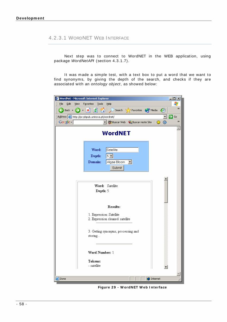
Development
- 58 -
4.2.3.1 WORDNET WEB INTERFACE
Next step was to connect to WordNET in the WEB application, using package WordNetAPI (section 4.3.1.7).
It was made a simple test, with a text box to put a word that we want to find synonyms, by giving the depth of the search, and checks if they are associated with an ontology object, as showed below:
Figure 29 - WordNET Web Interface
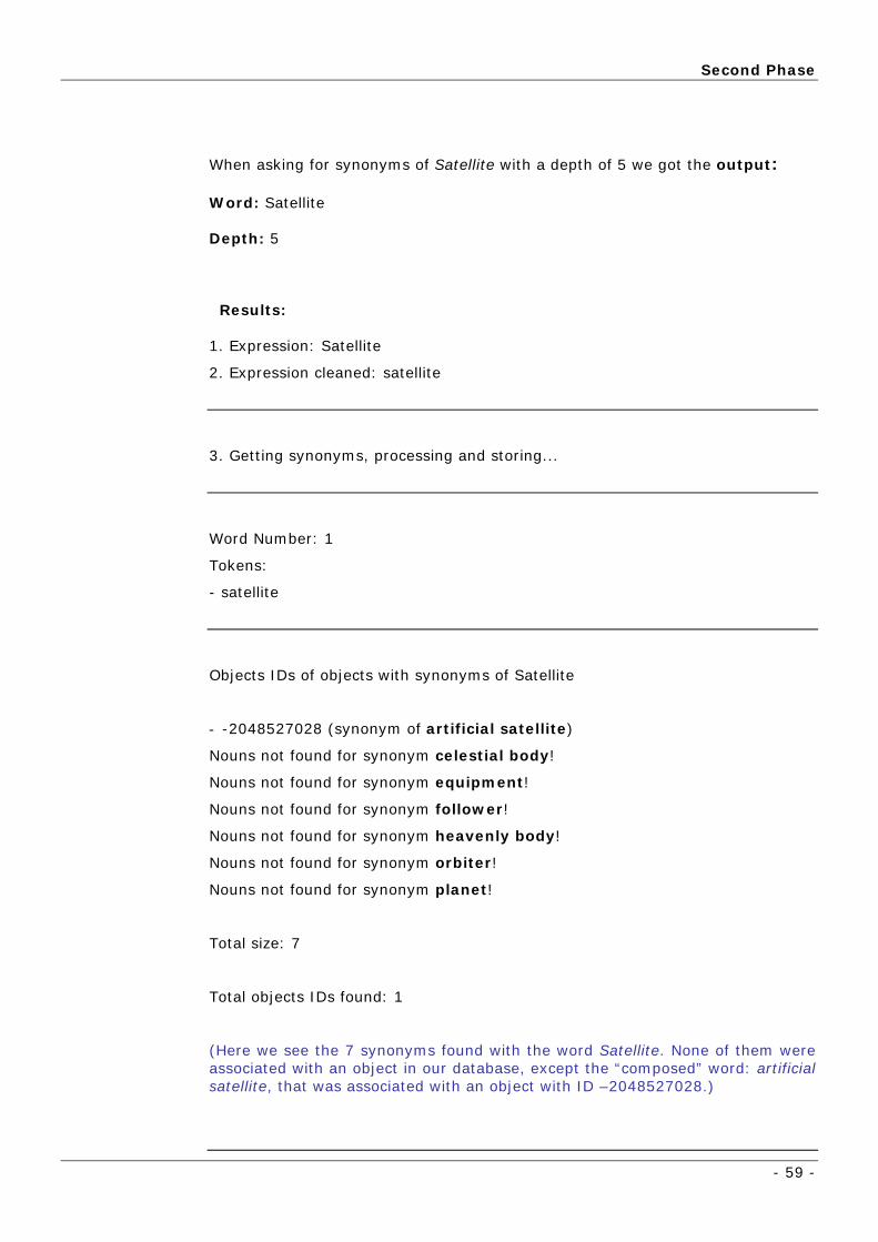
Second Phase
- 59 -
When asking for synonyms of Satellite with a depth of 5 we got the output:
Word: Satellite
Depth: 5
Results:
1. Expression: Satellite
2. Expression cleaned: satellite
3. Getting synonyms, processing and storing...
Word Number: 1
Tokens:
- satellite
Objects IDs of objects with synonyms of Satellite
- -2048527028 (synonym of artificial satellite)
Nouns not found for synonym celestial body!
Nouns not found for synonym equipment!
Nouns not found for synonym follower!
Nouns not found for synonym heavenly body!
Nouns not found for synonym orbiter!
Nouns not found for synonym planet!
Total size: 7
Total objects IDs found: 1
(Here we see the 7 synonyms found with the word Satellite. None of them were associated with an object in our database, except the “composed” word: artificial satellite, that was associated with an object with ID –2048527028.)

Development
- 60 -
4. Synonyms sort by relevance...
RELEVANCE SYNONYM
1 send
1 satellite
1 outer
1 orbiter
1 equipment
1 broadcast
1 beam
1 artificial satellite
1 air
2 planet
2 follower
3 heavenly body
3 celestial body
At this point, it was possible to access Protégé and WordNET, using a
web interface and calling developed Java packages.
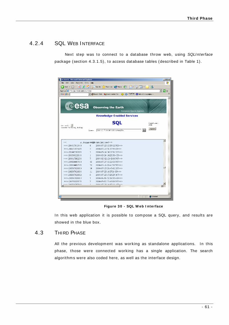
Third Phase
- 61 -
4.2.4 SQL WEB INTERFACE
Next step was to connect to a database throw web, using SQLInterface
package (section 4.3.1.5), to access database tables (described in Table 1).
Figure 30 - SQL Web Interface
In this web application it is possible to compose a SQL query, and results are
showed in the blue box.
4.3 THIRD PHASE
All the previous development was working as standalone applications. In this
phase, those were connected working has a single application. The search
algorithms were also coded here, as well as the interface design.
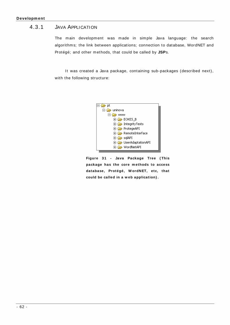
Development
- 62 -
4.3.1 JAVA APPLICATION
The main development was made in simple Java language: the search
algorithms; the link between applications; connection to database, WordNET and
Protégé; and other methods, that could be called by JSPs.
It was created a Java package, containing sub-packages (described next),
with the following structure:
Figure 31 - Java Package Tree (This
package has the core methods to access
database, Protégé, WordNET, etc, that
could be called in a web application).

Third Phase
- 63 -
4.3.1.1.1 DATABASE
A database was used to help managing some modules.
Following are the used database tables:
Table with object names (Protégé objects)
that appear in navigation box (see section
5.3), when application starts.
Protégé API (package
edu.stanford.smi.protege) doesn’t provide a
unique integer object identifier, to their
objects – although their names are unique.
With this table, we associate each object name
to a unique object id.
This table is used to in user adaptation
module (see section 4.3.1.6).
It relates a specific domain and object
with a weight. In date field it is saved last time
that weight was updated.
Each Protégé class, for a specific domain,
could have associated some synonyms. This
table associate nouns to them, and it is used
in search query (section 5.4).
Table 1 - Database Tables
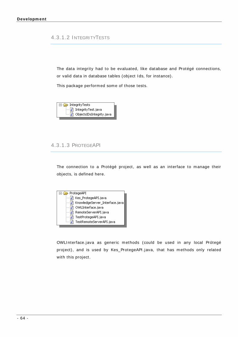
Development
- 64 -
4.3.1.2 INTEGRITYTESTS
The data integrity had to be evaluated, like database and Protégé connections,
or valid data in database tables (object Ids, for instance).
This package performed some of those tests.
4.3.1.3 PROTEGEAPI
The connection to a Protégé project, as well as an interface to manage their
objects, is defined here.
OWLInterface.java as generic methods (could be used in any local Prótegé
project), and is used by Kes_ProtegeAPI.java, that has methods only related
with this project.

Third Phase
- 65 -
4.3.1.4 REMOTEINTERFACE
This interface was developed from OWLInterface.java to access remote projects
(owl database projects), instead of local.
4.3.1.5 SQLAPI
This API provides some methods to access database (in this case, in SQLServer)
generically: creation of tables, selections, updates and other SQL queries.
4.3.1.6 USERADAPTATIONAPI
UserAdaptationAPI is the interface to methods related with user interface. It uses
sqlAPI to access database tables (described in Table 1 - Database Tables).
The main task of this package, is to consult weights of Protégé objects, from a
given domain, and last time they were acceded. This is used to show most
relevant objects first (with bigger weight). UserAdaptaionAPI also enables to
update weights.
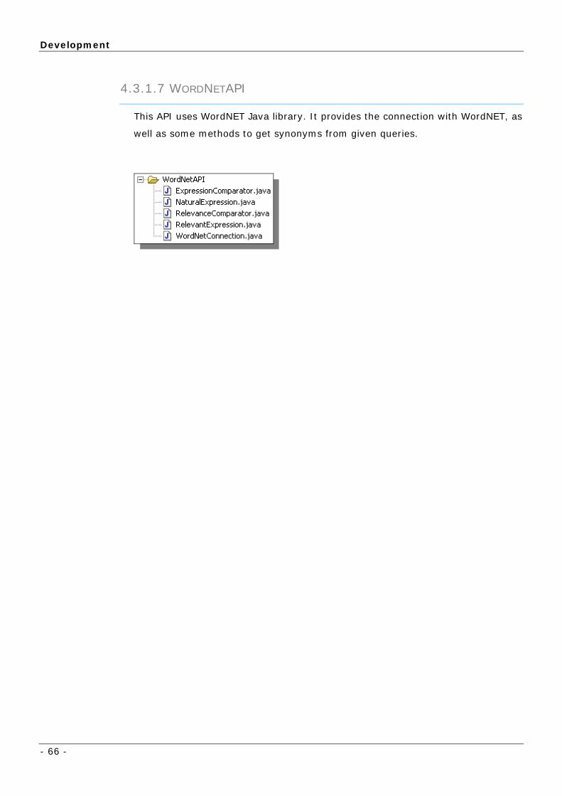
Development
- 66 -
4.3.1.7 WORDNETAPI
This API uses WordNET Java library. It provides the connection with WordNET, as
well as some methods to get synonyms from given queries.

Third Phase
- 67 -
4.3.1.8 PROTÉGÉ WEB INTERFACE
One of the most important first steps in developing was using the Protégé API
via a WEB application. With the know-how gained with Protégé Web Browser (section
4.2.1) it was possible to access and “play” with Protégé objects.
Figure 32 - Testing Protégé API via WEB interface.
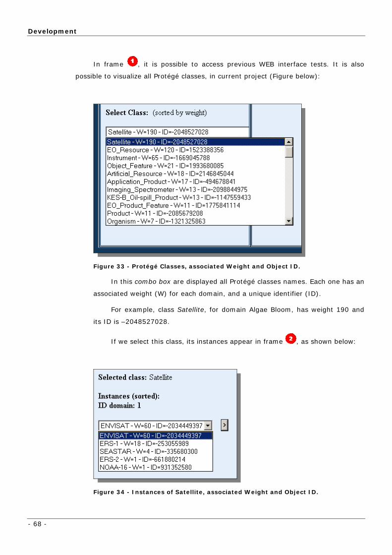
Development
- 68 -
In frame , it is possible to access previous WEB interface tests. It is also
possible to visualize all Protégé classes, in current project (Figure below):
Figure 33 - Protégé Classes, associated Weight and Object ID.
In this combo box are displayed all Protégé classes names. Each one has an
associated weight (W) for each domain, and a unique identifier (ID).
For example, class Satellite, for domain Algae Bloom, has weight 190 and
its ID is –2048527028.
If we select this class, its instances appear in frame , as shown below:
Figure 34 - Instances of Satellite, associated Weight and Object ID.
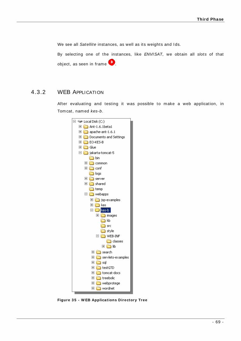
Third Phase
- 69 -
We see all Satellite instances, as well as its weights and Ids.
By selecting one of the instances, like ENVISAT, we obtain all slots of that
object, as seen in frame .
4.3.2 WEB APPLICATION
After evaluating and testing it was possible to make a web application, in
Tomcat, named kes-b.
Figure 35 - WEB Applications Directory Tree

Development
- 70 -
The deployment of the application on TOMCAT is as easy as copying kes-b folder
to webapps folder, as seen above. In the root of kes-b are the JSPs. All Java
packages should be in WEB-INF/lib directory.
KES-B Ontology Navigation: case studies
- 71 -
5 Application Presentation
5.1 KES-B ONTOLOGY NAVIGATION: CASE STUDIES
n capabilities needed, which are taken care off in other
parts of the project.
the possible
relations of the event selected by the user are highlighted in green:
With a model available, like the one in Figure 17, the first capability the
system can provide to the user is ontology navigation. Let’s look at some
examples. In these case studies we will describe the logic of the navigation and
ignore the visualizatio
The navigation through concepts of the ontology is possible starting from any
of them, but we are going to focus the navigation starting from the most
important: EO Event, EO Product Feature and Product (highlighted in yellow,
in Figure 36). A user could make a search for “oil spill”, for instance, in the EO
Events. A list of events related with oil spill will be obtained. After select an
event, the search can continue to all objects related with it, i.e., the user may
choose the path he wants to follow. The choices are given according to the
existing relations of the actual preferred object. In the figure below,

Application Presentation
- 72 -
Figure 36 - Part of the ontology diagram.
So, the user may expand his search to an EO Resource, an EO Product
Feature, a Product, or even to another EO Event. Considering, for instance,
the user wants the products related with the selected event (for example “Oil
spill in Galiza”), it would be possible to do so, just for getting all instances of
relation Detected_In linked to it, in a specific domain, obtaining, this way, all
products related.
5.2 FIRST PAGE
This section shows a demonstration of a possible scenario in the
implemented application.
The demonstration could be accessed via a web browser, on the following
address: http://pc-pub.uninova.pt/kes-b
When accessing this address, the initial search page is presented, as can be
seen in the following image.
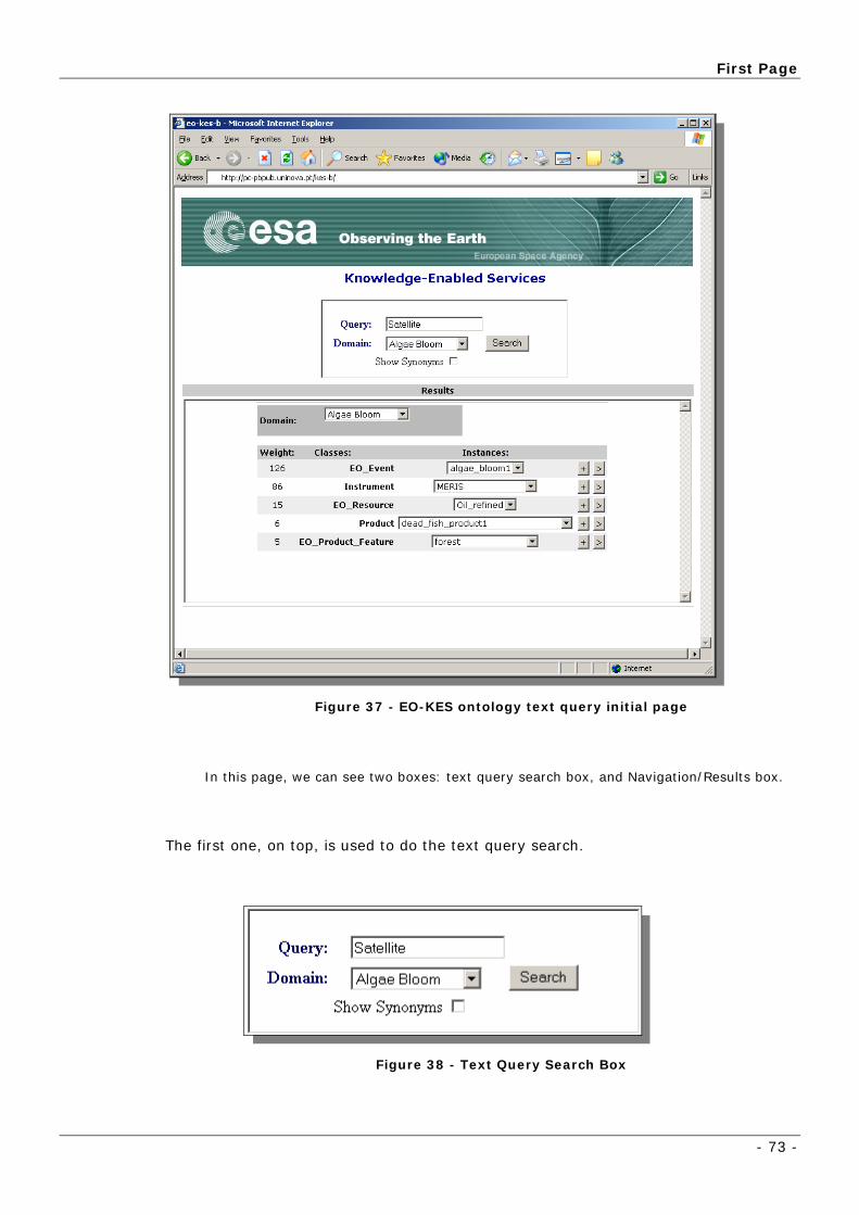
First Page
- 73 -
Figure 37 - EO-KES ontology text query initial page
In this page, we can see two boxes: text query search box, and Navigation/Results box.
The first one, on top, is used to do the text query search.
Figure 38 - Text Query Search Box

Application Presentation
- 74 -
In this box we can do a search, in a certain domain, using a text query.
In the box on bottom (Figure 39), it is possible to navigate throw ontology concepts
and instances. Results of text query will be shown on this box.
Figure 39 - Results and Navigation Box
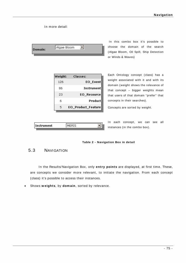
Navigation
- 75 -
In more detail:
In this combo box it’s possible to
choose the domain of the search
(Algae Bloom, Oil Spill, Ship Detection
or Winds & Waves)
Each Ontology concept (class) has a
weight associated with it and with its
domain (weight shows the relevance of
that concept – bigger weights mean
that users of that domain “prefer” that
concepts in their searches).
Concepts are sorted by weight.
In each concept, we can see all
instances (in the combo box).
Table 2 - Navigation Box in detail
5.3 NAVIGATION
In the Results/Navigation Box, only entry points are displayed, at first time. These,
are concepts we consider more relevant, to initiate the navigation. From each concept
(class) it’s possible to access their instances.
• Shows weights, by domain, sorted by relevance.

Application Presentation
- 76 -
Figure 40 - (Only concepts (and their instances) that are “Entry points” are
shown, at first)
• Buttons “ ” and “ ”:
o “ ” Expands to connected instances (connected with relations, associated with a
domain), increasing weight of concept, for this domain.
o “ ” Find automatically products which are associated (directly, or indirectly) with
selected instance, also increasing weight (bigger that weight increased with “ ”)
• Changing domain in Result window, weights are
different.
Figure 41 - (When domain is changed, weights are different)
• Choose Domain Oil Spill -> EO Resource “fish” →
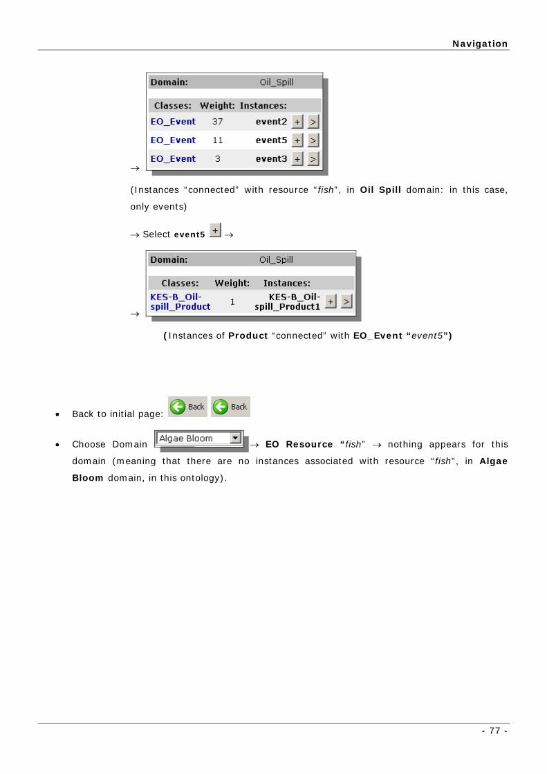
Navigation
- 77 -
→
(Instances “connected” with resource “fish”, in Oil Spill domain: in this case,
only events)
→ Select event5 →
→
(Instances of Product “connected” with EO_Event “event5”)
• Back to initial page:
• Choose Domain → EO Resource “fish” → nothing appears for this
domain (meaning that there are no instances associated with resource “fish”, in Algae
Bloom domain, in this ontology).

Application Presentation
- 78 -
5.4 SEARCH USING QUERY
Besides the navigation throw ontology’s concepts and instances, the user is
able to perform a text query. The system will try to match it with the most
similar data available, for the selected domain.
5.4.1 SEARCH PROCESS
Searches are made using different “layers”:
o 1 - First, check if each word in query box is a State, or an EO Resource.
If it has matches, gets pairs or related State/EO Resource, and shows
“connected” EO Events – finish search.
o 2 - Search query (words) in major concepts (entry points) – in ontology
concepts names;
- If found concepts, finish.
o 3 - Search query in instances of major concepts;
- If found instances, finish
o 4 - Search Synonyms of query in WordNet;
o 5 - Search objects in table of nouns (table, in a database, that relates some
nouns to protégé ontology objects)
- If found objects, finish
After this first approach, we developed another search functionality, to

Search using query
- 79 -
5.4.2 WEB APPLICATION
Figure 42 - Text Query Box
- Example:
o Query “Satellite” with Algae Bloom domain -> (Searches first in Classes/concepts)
→ → Choose ENVISAT → Click →
→ → → Click →
(Shows Instruments of “envisat”)
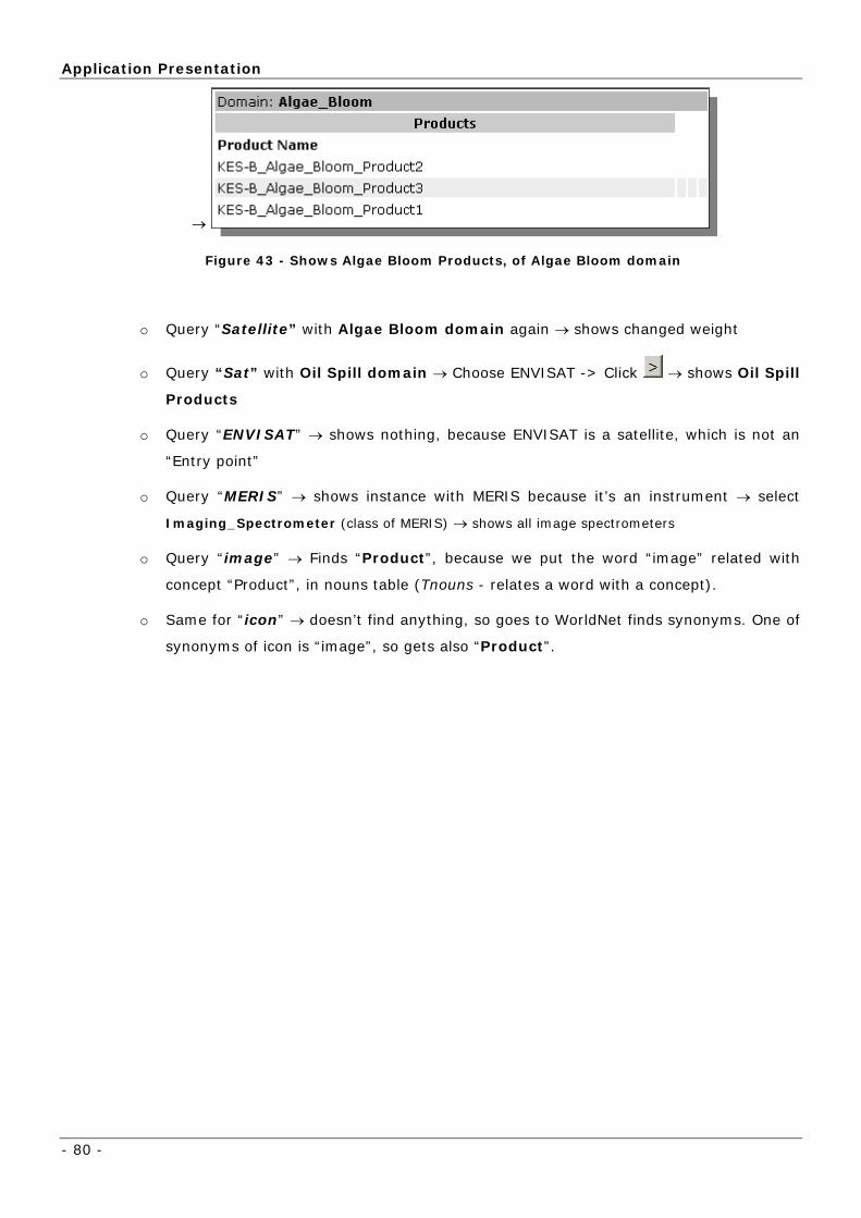
Application Presentation
- 80 -
→
Figure 43 - Shows Algae Bloom Products, of Algae Bloom domain
o Query “Satellite” with Algae Bloom domain again → shows changed weight
o Query “Sat” with Oil Spill domain → Choose ENVISAT -> Click → shows Oil Spill
Products
o Query “ENVISAT” → shows nothing, because ENVISAT is a satellite, which is not an
“Entry point”
o Query “MERIS” → shows instance with MERIS because it’s an instrument → select
Imaging_Spectrometer (class of MERIS) → shows all image spectrometers
o Query “image” → Finds “Product”, because we put the word “image” related with
concept “Product”, in nouns table (Tnouns - relates a word with a concept).
o Same for “icon” → doesn’t find anything, so goes to WorldNet finds synonyms. One of
synonyms of icon is “image”, so gets also “Product”.

Search using query
- 81 -
→
Figure 44 - Check Show Synonyms box, to see synonyms of word in WordNET
→ Figure 45 - Synonyms found in WordNET – only picture has a match with an
ontology concept
→ Go to Results Page →
→
Figure 46 - Concept Product is related with picture – shows all products
o Query misspelled of Satellite: “satelite” → shows Satellite, because we put this word
(satelite) in Tnouns table.
o Query “dead” with Oil Spill domain

Application Presentation
- 82 -
→
→
Figure 47 - “dead” is a state, so, found resources associated with that state, and
“connected” events
→ Select event1 (to obtain associated product features) →
→
Figure 48 - Ocean Product Features – button “ ” redirects to associated
products
→ Select ocean →

Search using query
- 83 -
→
Figure 49 - Associated products with ocean EO Product Feature

Conclusions
- 84 -
6 Conclusions
6.1 DEVELOPED WORK EVALUATION
group) converged to one, and I believe it will
not have more relevant changes.
ed in a database (much more appropriated to a web application – multi-
user).
ere it was
possible to see the different modules working together, with success.
6.2 FUTURE WORK
d with
GTD’s one, as well as exported to a database (in owl “database format”).
We will have 3 layers:
• n databases and
files) of the ontology, user adaptation and WordNET.
Ontology (developed in the
In programming, we had to take some decisions, due the lack of time, that
were not the more correct in terms of computer science. But, otherwise, they
would not be developed on time. One example is the local access to the Protégé
project (in a file), instead of using Protégé server, which uses a project
embedd
It was used a wide range of different and new technologies (still in
development) that had to be connected into a single web application. This was a
big challenge, but we did a small demonstration (chapter 5) wh
Next step, already running, is the integration of this project in the GTD
architecture (use the technology used by this Spanish company, and their
developed APIs). Ontology developed by UNINOVA was already integrate
Persistence layer - containing the storage data (i

Future Work
- 85 -
• Application Layer – with all the logic operations and searches. Is
connected to persistence layer, where it gets data, using servlets, and
sends it to presentation layer.
• Presentation Layer – this layer deals with client requests, gets data
from Application layer, in string format, and returns it to the browser,
formatted, using JSPs.
Figure 50 - Components Diagram.
Conclusions
- 86 -
6.3 INTERNSHIP EVALUATION
Integration in this work group was very easy and fun, because they are all
very nice and helpful people, since first day.
With this project I improved my knowledge especially in web applications:
configuration, some of the available technologies, J2EE environment,
deployment.
It was challenging to work in a field I didn’t know (web applications and
knowledge representation using ontology) with tools still in development (like
Protégé), which have a flaw in documentation.
On the other way, a big amount of documentation was generated in this
project: management reports (Milestone, Progress, …), technical specification
documents, design definition files, technical notes and meetings minutes.
One odd thing, at beginning, was the teleconference meetings, where we
discussed in english with ESA or team, only with phone, but after a few telecoms
we get used to.
Along the project, there were some challenges, ones harder then others, but
the goals were reached. The main issue is already outside of this project ambit,
but already begun: the integration with GTD technology, since they developed
their interface with some new technologies (Glue, Jetspeed, etc) providing a
overhead in the integration.
I’m proud of making my final degree in this well recognized and growing
research group, involved in some projects with ESA.
Internship Evaluation
- 87 -
7 Bibliography
1. Ontoknowledge, http://www.ontoknowledge.org/oil
2. OWL, http://www.w3.org/TR/owl-features/
3. Apache Jakarta Tomcat, http://jakarta.apache.org/tomcat/
hnology,
http://java.sun.com/products/jsp/
5. Cycorp, Inc., http://www.cyc.com/
6. OpenCyc.org, http://www.opencyc.org/
web.stanford.edu/people/kahsan/protege_browser/
Database,
http://www.cogsci.princeton.edu/~wn/
9. RDF, http://www.w3.org/TR/1999/REC-rdf-syntax-19990222/
10. Protégé, http://protege.stanford.edu/index.html
r English language,
http://www.cogsci.princeton.edu/~wn/
12. Eclipse, http://www.eclipse.org/
WP500 - Ontology and Knowledge Base - The Semantic Server.
2004.
14. Java Technology, http://java.sun.com
15. SW-EL'04, http://wwwis.win.tue.nl/SW-EL04/
16. Paul Stanley Software, http://www.pssuk.com/
and Autonomous Agents,
http://www2.uninova.pt/ca3/
-
4. J2EE JavaServer Pages Tec
7. Protégé Web Browser, http://smi-
8. WordNet - An Electronic Lexical
11. WordNet - a lexical database fo
13.
17. CA3 - Soft Computing
18. Baader, F., et al., Profitlich: Terminological knowledge
representation: A proposal for a terminological logic. Technical Memo TM-90

Bibliography
- 88 -
04. D sches Forschungszentrum für Künstliche Intelligenz GmbH (DFKI),
1991.
19. Benjamins, V.
eut
R., et al., (KA) 2 : Building ontologies for the internet:
9.
, A semantics and complete
ithm l
5. 9(2): p. 171-216.
pes. Reprinted from
al O
d
Reprinted from Journal Of Object-
s and
printed from Journal Of Object-
ion. Reprinted from Journal Of Object
et al., Wondertools ? a comparative study of ontological
neer
a mid term report. International Journal of Human-Computer Studies, 199
43(5/6): p. 907-928.
20. Borgida, A. and P.F. Patel-Schneider
algor for subsumption in the CLASSIC description logic. J. of Artificia
Intelligence Research, 1994. 1: p. 277-308.
21. Brachman, R.J. and J.G. Schmolze, An overview of the KL-ONE
knowledge representation system. Cognitive Science, 198
22. Brooks, F.P., No Silver Bullet: Essence and Accidents of Software
Engineering. IEEE Computer. 20: 10-19, 1987.
23. Chandrasekaran, B., J.R. Josephson, and e. al, What are ontologies,
and Why do we need them? IEEE Intelligent Systems, 1999: p. 20-26.
24. Conrad Bock and J.J. Odell, A More Complete Model of Relations and
Their Implementation - Part I: Relations as Object Ty
Journ f Object-Oriented Programming Vol 10, No 3. June 1997 Copyright
© 1997 SIG Publications, Inc, New York, NY, 1997.
25. Conrad Bock and J.J. Odell, A More Complete Model of Relations an
Their Implementation Part II:Mappings.
Oriented Programming Vol 10, No 6. October 1997 Copyright © 1997 SIG
Publications, Inc, New York, NY, 1997.
26. Conrad Bock and J.J. Odell, A More Complete Model of Relation
Their Implementation Part III: Roles. Re
Oriented Programming Vol 11, No 2. May 1998 Copyright © 1998 SIG
Publications, Inc, New York, NY, 1998.
27. Conrad Bock and J.J. Odell, A More Complete Model of Relations and
Their Implementation Part IV: Aggregat
Oriented Programming Vol 11, No 5. September 1998 Copyright © 1998 SIG
Publications, Inc, New York, NY, 1998.
28. Duineveld,
engi ing tools. International Journal of Human-Computer Studies 52(6):
1111--1133, 2000.
29. Fensel, D., Ontologies: A Silver Bullet for Knowledge Management
and Electronic Commerce, Springer. 2000.

Internship Evaluation
- 89 -
30. Genesereth, M.R. and N.J. Nilsson, Logical Foundations of Artificial
Intelligence. 1987: Morgan Kaufmann Publishers.
31. Gomez Perez, A. and V.R. Benjamins, Applications of ont
problem-solving methods. AI-Magazine, 1999. 20((1)): p.
ologies and
119-122.
riniciples for the Design of Ontologies Used for
led
ledge Bases:
rds s:
-32, 1995.
c
(3):267-293, 1999.
d
ions of Ontologies and Problem-solving Methods,
or the predicate calculus.
the
tology-Oriented Design and Programming, in
led
ective. G.
ations, Stanford, 1996.
32. Gruber, T., A translation Approach to portable ontology
specifications. Knowledge Acquisition 5: 199-220, 1993.
33. Gruber, T., Towards P
Know ge Sharing. International Journal of Human-Computer Studies
43(5/6): 907-928, 1995.
34. Guarino, N. and P. Giaretta, Ontologies and Know
Towa a Terminological Clarification. Towards Very Large Knowledge Base
Knowledge Building & Knowledge Sharing: 25
35. Guarino, N., Formal Ontology and Information Systems. FOIS'98,
Trento, Italy, Amsterdam, IOS Press, 1998.
36. Horrocks, I. and P.F. Patel-Schneider, Optimising description logi
subsumption. Journal of Logic and Computation, 9
37. Karp, P.D., V.K. Chaudhri, and J. Thomere, XOL: An XML-base
ontology exchange language. versión 0.3. 1999.
38. Klein, M., et al. The relation between ontologies and schema-
languages: Translating OIL-specifications in XML-Schema. in Proceedings of
the Workshop on Applicat
14th European Conference on Artificial Intelligence ECAI'00,. 2000. Berlin,
Germany August 20-25.
39. MacGregor, R.M., A description classifier f
Proceedings of the Twelfth National Conference on Artificial Intelligence,
pages 213-220, Seattle, Washington, USA, 1994.
40. McCarthy, J. and P. Hayes, Some Philosophical Problems from
Standpoint of Artificial Intelligence. Machine Intelligence 4, 1969.
41. Musen, M.A., On
Know ge Engineering and Agent Technology, J. Cuena, Editor. 2000,
Amsterdam, IOS Press.
42. Nebel, B., Artificial intelligence: A computational persp
Brewka, editor, Principles of Knowledge Representation, Studies in Logic,
Language and Information. CSLI public
Bibliography
- 90 -
43. Norman, D.A., Cognitive Engineering. User-Centered System Design,
Hillsdale NJ, Laurence Erlbaum, 1986.
44. Noy, N.F. and D.L. McGuinness, Ontology Development 101: A Guide
led services
onference on Theory and Applications of
led
torial on Ontological Engineering. IJCAI, 1999.
as,
demic Press, 1993.
.
ress.
telligent
001.
V.R. Benjamins, and D. Fensel, Knowledge engineering:
nd
d B.J. Wielinga, Using explicit
ntologies in KBS development. International Journal of Human-Computer
Studies, 1997. 46((2/3)): p. 183-292.
to Creating Your First Ontology Stanford University. Stanford, CA, 94305 -
[email protected] and [email protected], 2000.
45. Pereira, A., et al. An ontology to support knowledge enab
on earth observation. in ESA-EUSC C
Know ge driven Image Information Mining, with focus on Earth
Observation,. 2004. Madrid, Spain.
46. Perez, A.G., Tu
47. Reed, S.L. and D.B. Lenat, Mapping Ontologies. Cyc. Austin, Tex
Cycorp, Inc.: 6, 2002.
48. Rolf Pfeifer and C. S., Understanding Intelligence. Cambridge -
Massachusetts, MIT Press, 2000.
49. Schreiber, G., B. Wieling, and others, KADS: A Principled Approach
to Knowledge-Based System Development. London, Aca
50. Schreiber, G.H.A., et al., Knowledge Engineering and Management
The CommonKADS Methodology. 1999: The Mit P
51. Schreiber, A.T.G., et al., Ontology -based Photo Annotation. IEEE
Intelligent Systems, 2001. May/June: p. 66-74.
52. Staab, et al., Knowledge Processes and Ontologies. IEEE In
Systems, Special Issue on Knowledge Management. 16, 2001.
53. Storey, M.-A., Information Visualization and Knowledge
Management. Dept. of Computer Science Uvic - CSc 586a/SENG 480a, 2
54. Studer, R.,
Principles and methods. Data and Knowledge Engineering (DKE), 25(1-
2):161-197, 1998.
55. Uschold, M. and M. Grüninger, Ontologies: Principles, methods a
applications. Knowledge Engineering Review, 11(2), 1996.
56. Van Heijst, G., A.T. Schreiber, an
o

Annex 1 – KES-B Ontology Design Dictionary
- 91 -
8 Annexes
8.1 ANNEX 1 – KES-B ONTOLOGY DESIGN DICTIONARY
efinition for each concept used in the ontology,
organized in alphabetic order.
Algorithm
hm is a precise rule (or set of rules) specifying how to solve some
problem.
rocedure, by transforming one
or more raw products into transformed products.
Appearance
The appearance is the outward or visible aspect of a person or thing.
Application product
ures specifically targeted
for application domains. For example, Winds & waves.
Artificial Resource
ing from natural origins, i.e. it is a man-
made process rather than natural one.
utor is the agent responsible for the delivery of Products to other gents.
Death
e permanent end of all life functions in an organism or part of an
organism.
Event
t is related with
resources with product features and products themselves.
In this annex is presented a d
An algorit
In the current case it is part of a transformation p
These are products derived from transformation proced
An artificial resource is resource not aris
Distributor A Distriba
Death is th
Anything that happens within EO Domain is an Event that should be registered
by experts to assure the service to other agents. The even

Annexes
- 92 -
Feature Extraction
Feature Extraction Procedures manipulate Products and/or “Non-EO data” in
order to prepare Features.
Geo-coded area
It includes the geographic coordinates of a segment area being considered.
Imaging Spectrometer
The spectroscope is used for obtaining a mass spectrum by deflecting ions into a
thin slit and measuring the ion current with an electrometer. The Imaging
spectrometers measure the radiance leaving marine waters in the visible and
near infrared spectrum.
Injury
An injury can be considered any physical damage to a body caused by an
accident of any type.
Instrument
An instrument is a part of a Satellite, usually a sensor. In our core structure, we
consider three instruments: Radiometer, Synthetic Aperture Radar and
Spectrometer. For example, MERIS is a spectrometer.
Knowledge Domain
A Knowledge Domain is a specified sphere of knowledge
Natural Resource
A natural resource is something that exists or is produced by nature, e.g. Water,
Land or Atmospheric.
Non-EO product
This type of products are the ones not produced by EO instruments, e.g. in-situ
measures.
Operational product
An operational product has its origin in instruments or transformation procedure
and they are provided by ESA, e.g. any level, L1, L2 etc.
Organism
Organisms are living things of flora and fauna that are relevant to the EO
Domain. An organism defined in this way can be of two different types
(Organism Type): animal or vegetal (fauna or flora) and belong to a specific
family (Organism Family).

Annex 1 – KES-B Ontology Design Dictionary
- 93 -
Organism Family
From biology, an organism family is a taxonomic group containing one or more
genera.
Organism Type
An organism type consists of the top-level types or classes of an organism:
animal, vegetal, etc.
Product
Products can be derived from other products by using transformation procedures
that are based in algorithms. Products can also be derived from: operational
(generic or other); application (winds &waves, oil-spill, algae bloom); non-EO
data.
Product feature
Product features include both physical features (e.g. ocean colour, water
temperature) and object features (ship, oil-spill, forest). They are extracted
from products and can be analysed in events. The features can also be viewed
as properties of resources (e.g. ocean colour).
Radiometer
A radiometer is an instrument to detect and measure radiant energy
(electromagnetic or acoustic). Microwave radiometer is the (passive) technique
of measuring the electromagnetic radiation emitted by a surface.
Reproduction
Reproduction is the process of generating offspring. An alteration in this state
can be an abnormal decrease or increase.
Resource
A resource is a new or reserve supply that can be drawn upon when needed. It
can also be an available source of wealth. In the EO Domain context, resources
can be natural (e.g. ocean, mountain, etc) or artificial (e.g. oil), or living
organisms (e.g. algae, fish).
State
The way something is with respect to its main attributes. At some moment
something has a state, and a resource, such as an organism (animal or plant)
that may die or even an ocean surface region that may have its appearance
altered.

Annexes
- 94 -
Satellite
A spacecraft orbiting the earth, carrying instruments and doing observation of
the natural resources and atmosphere parameters sending the data to a control
centre. Relevant satellites for the EO-KES are ENVISAT, ERS-1 and ERS-2.
Synthetic Aperture Radar
Synthetic Aperture Radar (SAR) is a sophisticated unique and valuable remote
sensing tool. Microwave radar system, transmits energy and receives what is
returned back (scattered), with a unique all-weather
imaging capability.
Transformation procedure
Transformation procedures can be derived from feature extraction processes or
production procedures depending, respectively, if we are manipulating raw
products or non- EO data to prepare other products that have features. It uses
algorithms to perform the transformation.