seismic response of typical fixed jacket type · pdf fileseismic response of typical fixed...
TRANSCRIPT
International Journal of Advance Research In Science And Engineering http://www.ijarse.com
IJARSE, Vol. No.3, Special Issue (01), September 2014 ISSN-2319-8354(E)
24 | P a g e
SEISMIC RESPONSE OF TYPICAL FIXED JACKET
TYPE OFFSHORE PLATFORM UNDER SEA WAVES: A
REVIEW
Abhijeet A. Maske1, Nikhil A. Maske
2 , Preeti P. Shiras
3
1Civil Engineering Department, III Semester M-Tech Structural Engineering,
Government College of Engineering, Amravati, Maharashtra, (India)
2,3
Civil Engineering Department, Assistant Professor, Nagpur Institute of Technology,
Rashtrasant Tukdoji Maharaj, NagpurUniversity, Nagpur, Maharashtra, (India)
ABSTRACT
Offshore platforms in seismically active areas should be designed to service severe earthquake excitations with no
global structural failure. In seismic design of offshore platforms, it is often necessary to perform a dynamic analysis
.This study summarizes the nonlinear dynamic analysis of a 3-D model of a typical Jacket-Type platform which is
installed in Persian Gulf (SPD1), under simultaneously wave and earthquake loading has been conducted. It is
assumed that they act in the same and different directions. The structure is modeled by finite element software
(ANSYS Inc.). It is concluded that when the longitudinal components of the earthquake and wave are in different
directions, an increase on the response of platform can be seen.
Index Terms: Offshore Platforms, Dynamic Analysis, Earthquake Loadings, Jacket-Type Platform,
Finite Element Software (ANSYS Inc).
I INTRODUCTION
Offshore construction is the installation of structures and facilities in a marine environment, usually for the production
and transmission of electricity, oil, gas and other resources. An oil platform, (offshore platform) is a large structure
with facilities to drill wells, to extract and process oil and natural gas, and to temporarily store product until it can be
brought to shore for refining and marketing.
The purpose of the study is to identify the adequate capacity of existing offshore structures in under earthquake effect
as well as wave loads. Another purpose of this study is to analyze the behavior of the offshore structures under the
earthquake and sea waves using nonlinear dynamic analysis i.e. Time history analysis. The main objective of this
study is to determine the effect of earthquake loading and sea waves acting simultaneously to the existing structure.
II TYPES OF OFFSHORE PLATFORM

International Journal of Advance Research In Science And Engineering http://www.ijarse.com
IJARSE, Vol. No.3, Special Issue (01), September 2014 ISSN-2319-8354(E)
25 | P a g e
Fig : 1), 2) conventional fixed platforms; 3) compliant tower; 4, 5) tension leg platform; 6) spar
platform; 7,8) semi-submersibles; 9) floating production, storage, and offloading facility; 10) sub-sea
completion and tie-back to host facility.
II LITERATURE REVIEW
2.1 Morrison’s Equation
The resulting force on a body in an unsteady flow is given by,
Fx(t)=ρ*Cm*A*Ů+0.5ρ* Cd*D*U|U|
Where,
ρ = Density of water
Cm = Mass coefficient
Cd = Drag coefficient
U = Velocity
Ů = Acceleration
Khosro Bargi et.al (2011)
Assessed seismic response of fixed jacket type offshore platform under sea waves according to the API
Recommended Practice 2A-WSD.
The results obtained from study show that the maximum displacement response of platform under combination of two
loads (earthquake and wave loads) are more than maximum displacement response of earthquake load alone.
Shehata E. Abdel Raheem (2013)
Presents the study of nonlinear response of fixed jacket type offshore platform currently installed in Suez gulf, Red
sea and it is analyzed using nonlinear dynamic analysis program SAP 2000.

International Journal of Advance Research In Science And Engineering http://www.ijarse.com
IJARSE, Vol. No.3, Special Issue (01), September 2014 ISSN-2319-8354(E)
26 | P a g e
Concluded that the reduction of dynamic stress amplitude of an offshore structure by 15% can extend the service life
over two times, and can result in decreasing the expenditure on the maintenance and inspection of the structure.
Elsayed M.A.Abdel Aal et.al (2012)
Presents the study about fixed jacket type offshore platform. From results of non-linear analysis, they concluded that
nonlinear analysis is required for a realistic determination of the behavior of structure and to obtain an economical
and rational structural design.
American Petroleum Institute ,API-RP2A 1997 (2.2)
The majority of world’s platforms have been designed according to the different editions of recommended practice by
the American Petroleum Institute (API)
Environmental loads with the exception of earthquake, should be combined in a manner consistent with the
probability of their simultaneously occurrence during the loading condition being consider.
2.2 Concluding Remarks
The research has shown that nonlinear analysis is very essential to the offshore structure which is one of the important
structures, subjected to earthquake and sea waves. Therefore, an attempt has been made to investigate the behavior of
offshore structure to sustain under earthquake as well as wave effect using Time History analysis.
III METHODOLOGY
This study is based on nonlinear analysis of fixed jacket type platform of offshore structure. In this chapter summary
of various parameters defining the computational model and the frame geometry considered for this study are
explained. Accurate modeling of the nonlinear properties of various structural elements is very important in nonlinear
analysis.
3.1 Structure Geometry
The general purpose finite element analysis software ANSYS 9 was used to perform analyses. Fig. 3.1 shows a 3D
Computer models of the fixed jacket based offshore platform.
Fig 3.1 Schematic Model of Jacket-Type Platform

International Journal of Advance Research In Science And Engineering http://www.ijarse.com
IJARSE, Vol. No.3, Special Issue (01), September 2014 ISSN-2319-8354(E)
27 | P a g e
The Seismic response of a fixed jacket type offshore platform will be carried out Non-linearly i.e. by Time history
analysis. The different time histories to be used are as follows:
1. El-Centro
2. Kobe
3. Tabas (Source: http://PEER.Berkeley.edu.html)
Figures below, showing the longitudinal and horizontal components of time-history of earthquake displacement
which are used in this study.
Fig 3.2 Time history Longitudinal and horizontal component of El Centro
Fig 3.3 Time history Longitudinal and horizontal component of Cobe
Fig 3.4 Time history Longitudinal and horizontal component of Tabas

International Journal of Advance Research In Science And Engineering http://www.ijarse.com
IJARSE, Vol. No.3, Special Issue (01), September 2014 ISSN-2319-8354(E)
28 | P a g e
3.2 Analysis Procedure
Wave and earthquake phenomena occur at different direction. Studied structure is symmetric around Y direction,
therefore according to Figure 3.5, for analysis, four directions for earthquake and wave loads imposed on structure are
selected.
Fig 3.5 Wave and Earthquake imposed direction
In order to evaluate the response of studied platform under earthquake and wave loads, simultaneously four studies
regarding to wave and earthquake directions have been performed. In the first study, only earthquake load analysis
was performed at four directions Figure 3.5.
Regarding to the random features of sea waves, since it is possible that the direction of wave and earthquake loads to
be different, in the second analysis, earthquake longitudinal component fixed at zero direction simultaneously acts
with wave load at four directions.
For tertiary analysis, wave load component fixed at zero direction simultaneously acts with earthquake longitudinal
component at four directions. For all conditions, both earthquake longitudinal and horizontal components were used.
Finally, analysis for 100 years wave was performed at four directions.
IV RESULT AND DISCUSSION
The selected model is analyzed using non linear dynamic analysis. At first results from dynamic analysis for modal
verification and then results from time history analysis are discussed in this chapter.
4.1 Results from Dynamic Analysis
A dynamic analysis is normally mandatory for every offshore structure, but can be restricted to the main modes in the
case of stiff structures. The first step in a dynamic analysis consists of determining the principal natural vibration
mode shapes and frequencies of the undamped, multi-degree-of-freedom structure. First rigid structures have a
fundamental vibration period well below the range of wave periods (typically less than 3sec.), first and second modes
are effective on structure behavior and higher order mode shapes having less effects on structure behavior.
In order to model verification, 10 first modes of structure compared with initial design modes. It shows that first and
second modes correspond with fact and high order modes have approximately 35% - 50% difference, because jacket
modeled with equivalent pile length. This comparison is show in Table 4.1.

International Journal of Advance Research In Science And Engineering http://www.ijarse.com
IJARSE, Vol. No.3, Special Issue (01), September 2014 ISSN-2319-8354(E)
29 | P a g e
Table 4.1: Comparison of results
Mode Model Periods (sec) SPD1 Periods (sec) % Error
1 2.02 2.05 -1.4
2 1.89 1.9 -0.5
3 0.77 1.52 -49.0
4 0.47 0.82 -42.1
5 0.44 0.75 -41.1
6 0.32 0.53 -39.1
7 0.32 0.5 -36.4
8 0.30 0.49 -38.3
9 0.30 0.47 -36.0
10 0.29 0.46 -36.5
4.2 Results from Time History Analysis
Results obtained from different time history analysis at node 589 (one of the dek’s node) as shown in figures given
below.
Fig 4.1 Response of platform in X direction Fig 4.2 Response of platform in Y direction
at node 589 at node 589

International Journal of Advance Research In Science And Engineering http://www.ijarse.com
IJARSE, Vol. No.3, Special Issue (01), September 2014 ISSN-2319-8354(E)
30 | P a g e
Fig 4.3 Response of platform in X direction Fig 4.4 Response of platform in Y direction
at node 589 at node 589
Fig 4.5 Response of platform in X direction Fig 4.6 Response of platform in Y direction
at node 589 at node 589 (Loads: pink line: earthquake; Blue line: earthquake and wave; Yellow line: 100 years wave)
Drift of Structure
This study shows significant difference between drift under simultaneously wave and earthquake loads compared
with regulations criteria (for earthquake load). This difference is shown in Table 4.2.
Table 4.2: Difference between Drifts.
Earthquake El-Centro Kobe Tabas
Direction X Y X Y X Y
Difference ratio between
wave and earthquake
compared with earthquake
1.97 1.94 2.65 1.94 1.71 1.75
International Journal of Advance Research In Science And Engineering http://www.ijarse.com
IJARSE, Vol. No.3, Special Issue (01), September 2014 ISSN-2319-8354(E)
31 | P a g e
alone
Difference percent ratio
between wave and
earthquake compared with
100 years wave
2.74 2.41 2.15 2.13 6.81 5.74
The response of jacket under wave loading and El-Centro seismic loading was studied on severe direction separately.
This comparison was done for other seismic records and other conditions. Those results are shown below.
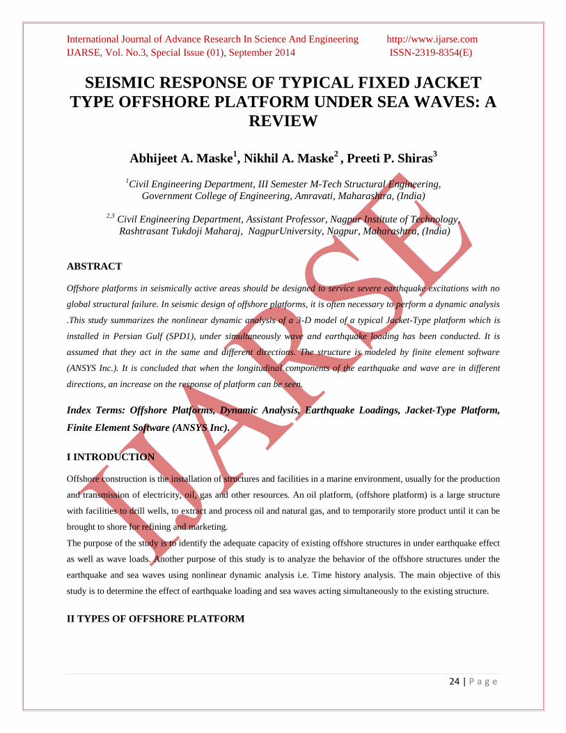
This method of analysis considers the wave in one direction is constant and earthquake lateral component direction is
applied 45 degrees by 45 degrees. The drift of node 589 is evaluated in X direction. Figure 4.7 shows the result of
effect of non-directional act of wave and earthquake components on jacket.
Fig 4.7 Comparison of X direction Drift when water wave lateral component is applied on
zero degree and seismic lateral component is applied 450 by 450.
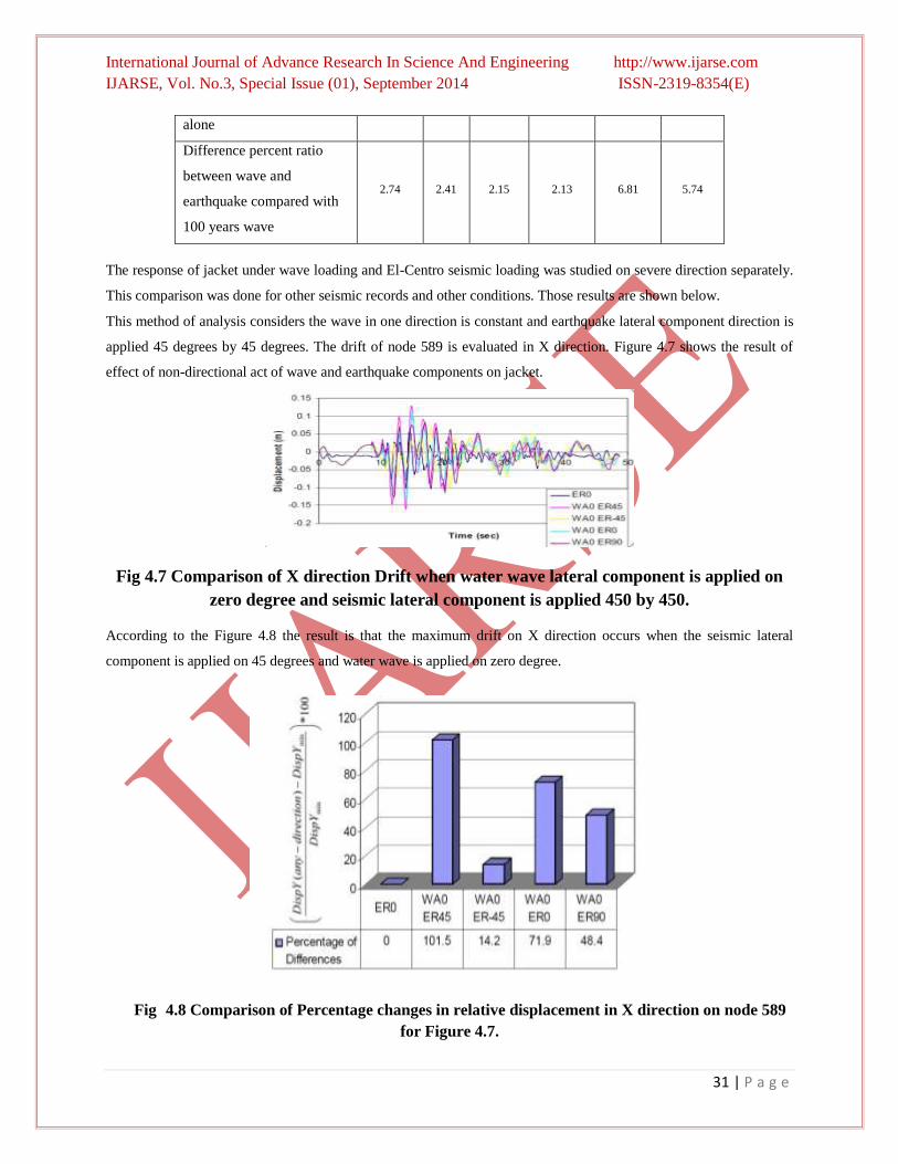
According to the Figure 4.8 the result is that the maximum drift on X direction occurs when the seismic lateral
component is applied on 45 degrees and water wave is applied on zero degree.
Fig 4.8 Comparison of Percentage changes in relative displacement in X direction on node 589
for Figure 4.7.

International Journal of Advance Research In Science And Engineering http://www.ijarse.com
IJARSE, Vol. No.3, Special Issue (01), September 2014 ISSN-2319-8354(E)
32 | P a g e
Figure 4.9 shows the comparison effect of non-directional of water wave and seismic lateral component such as
conditions discussed above, but Y direction drift is studied.
Fig 4.9 Comparison of Y direction Drift when the water wave lateral component is applied on zero
degree and seismic lateral component is applied 450 by 450.
According to Figure 4.10 the result is that the maximum drift on Y direction occurs when the seismic lateral
component is applied on –45 degrees and water wave is applied on zero degree.
Fig 4.10 Comparison of Percentage changes in relative displacement in X direction on node 589 for
Figure 4.9.

International Journal of Advance Research In Science And Engineering http://www.ijarse.com
IJARSE, Vol. No.3, Special Issue (01), September 2014 ISSN-2319-8354(E)
33 | P a g e
Figure 4.11 shows the comparison of non-directional effect of water wave and seismic lateral component applied
simultaneously on jacket. In this case the direction of seismic lateral component is constant on zero degree and water
wave direction changes 45 degrees by 45 degrees. Drifts are compared in X direction for node 589.
Figure 4.11 Comparison of drifts on X direction when seismic lateral is applied on zero degree and
water wave direction changes 450 by 450.
Figure 4.12 shows that maximum drift on X direction when the seismic lateral component is applied in zero degree
and water wave is applied in -45 degrees. The same comparison for drift in Y direction for node 589 is given below.
Figure 4.12 Comparison of Percentage changes in relative displacement in X direction on node 589
for Figure 4.11.

International Journal of Advance Research In Science And Engineering http://www.ijarse.com
IJARSE, Vol. No.3, Special Issue (01), September 2014 ISSN-2319-8354(E)
34 | P a g e
Figure 4.13 shows the comparison of non-directional effect of water wave and seismic lateral component applied
simultaneously on jacket. In this case the direction of seismic lateral component is constant on zero degree and water
wave direction changes 45 degrees by 45 degrees. Drifts are compared in Y direction for node 589.
Figure 4.13 Comparison of drifts on Y direction when seismic lateral is applied on zero degree and
water wave direction changes 45 degrees by 45 degrees.
Finally, Figure 4.14 shows that maximum drift on Y direction when the seismic lateral component is applied in zero
degree and water wave is applied in 45 degrees.
Fig.4.14 Comparison of Percentage changes in relative displacement in Y direction on node 589 for
Figure 4.13.

International Journal of Advance Research In Science And Engineering http://www.ijarse.com
IJARSE, Vol. No.3, Special Issue (01), September 2014 ISSN-2319-8354(E)
35 | P a g e
CONCLUSION
The response of fixed jacket type offshore platform was investigated using the time history analysis. As a result of the
work that was completed in this study, the following conclusions were made:
When the longitudinal components of the earthquake and wave are in different directions, an increase on the
response of platform can be seen.
The displacement for earthquake load alone is less than the displacement for the combination of earthquake
and wave loads.
This study shows significant difference between drift under simultaneously wave and earthquake loads
compared with regulations criteria (for earthquake load).
It may also conclude that nonlinear response investigation is quite crucial for safe design and operation of
offshore platform.
The time history analysis is a relatively simple way to explore the non linear behavior of offshore structures.
REFERENCES
[1] Khosro Bargi, S.Reza Hosseini and Mohommad H. Tadayon “Seismic response of a Typical Fixed Jacket type
offshore platform (SPD1) under sea waves”, Open journal of marine science,1,36-42 (2011)
[2] Shehata E. Abdel Raheem , “Nonlinear response of fixed jacket offshore platform under structural and wave
loads” Coupled system mechanics, VOL. 2, NO. 1 (2013).
[3] Elsayed M.A.Abdel Aal and Fayez K. Abdel Seed, “Nonlinear analysis of offshore structures under wave
loading”, 15th World conference on earthquake engineering, (2012).
[4] American Petroleum Institute (API) , API-RP2A-WSD “Recommended practice for planning, designing and
constructing fixed offshore platforms.