seismic response of structures free to rock …3)0141.pdf · foundations under seismic attack. ......
TRANSCRIPT
141
S E I S M I C R E S P O N S E OF S T R U C T U R E S F R E E T O
R O C K ON T H E I R F O U N D A T I O N S
M . J . N . P r i e s t l e y * , R.J. E v i s o n * * , A.J.Carr***
SUMMARY
The possibility of foundation rocking of shear wall structures designed to NZS 4203 is discussed. Theory developed by Housner for the free rocking of a rigid block is compared with experimental results from a simple structural model with a number of different foundation conditions. A simple design method for assessing maximum rocking displacements, using equivalent elastic characteristics and a response-spectra approach is proposed, and compared with results from simulated seismic excitation of the model using an electro-hydraulic shake-table. A typical design example is included.
1. INTRODUCTION
Post-mortems on structural response subsequent to seismic attack have revealed unexpected behaviour on some types of structures that can only be attributed to rocking of the entire structure on its foundations. For example, several seemingly unstable golf-ball-on-a-tee types of elevated reinforced-concrete water tanks incurred minimal damage during the Chilean earthquake of May 1960, while more stable ground-supported reinforced concrete tanks were severely d a m a g e d ( 1 ) .
Inspection of the foundations of the apparently unstable tanks revealed clear evidence that the structures had rocked on their foundations. Investigations after the Arvin-Tehachapi earthquake (California, July 1952) indicated that a number of tall petroleum-cracking towers had escaped serious damage by stretching their anchor bolts, and rocking on their foundation pads * ' , It was also noted that free-standing stone pillars supporting heavy statues in Indian cities remained intact while more stable structures in the vicinity were reduced to rubble.
Seismic response involving uplift of the major portion of the base (rocking) is not, however, limited to such unstable structures as described in the previous paragraph. Design to the provisions of NZS 4203: 1976*3) c a n
result in situations where rocking of part or all of the structure under seismic attack is probable. Consider the simplified structural system illustrated in Fig. la, consisting of end shear walls providing the required N-S seismic resistance, with vertical load mainly supported by flexible interior columns which do not contribute significantly to lateral resistance. Despite the comparatively squat nature of the structure, the high ratio of tributary floor mass for transverse seismic response to tributary floor mass for vertical loads can result in the base seismic overturning moment exceeding the restoring gravity moment.
In some c a s e s , the designer is not
* Reader in Civil Engineering, University of Canterbury.
** Construction Engineer, N . Z . Structures Ltd. *** Senior Lecturer in Civil Engineering,
University of Canterbury.
required to inhibit the rocking that would result, by incorporating a massive foundation beam (Fig. 1 6 ) . If the structure in Fig. la is designed to NZS 4 2 0 3 f o r Zone A in Reinforced Concrete using Grade 380 steel, a Structural Type factor S = 1.6 and Materials Factor M = 1.0 are appropriate. Assuming the wall to be designed on the basis of a flexural undercapacity factor of <j)f = 0.90, the foundations would need to be designed for an effective S x M value of
reinforced concrete:
S x M x - ^ = 1 . 6 x l . 0 x ^r^-cj>f 0.9
= 2.4 ,
where $ Q = 1.3 5 is the appropriate overcapacity factor to ensure no rocking or foundation yield. If the walls were constructed of reinforced masonry, <J)f = 0.65 and M - 1.2 are required, and thus
reinforced masonry: ^ ™ ^ ° i r n o 1.35 S x M x - — = 1.6 x 1.2 x 7r—^-7=-cp̂ 0 . ob
= 4.0 ,
However, NZS 4203 states
"... no foundation system need be designed to resist forces and moments greater than those resulting from a horizontal force corresponding to S x M = 2" clause 3.3.6.3.1 The consequences of this load-limitation clause are that some structural systems will be allowed to rock on their foundations under seismic attack.
It is the writers contention that this anomoly rather than representing an unsafe condition, may result in considerable advantages by allowing rocking in some cases. In Fig. lc a comparatively light foundation is provided, designed on the basis of S x M = 2.0 (for e x a m p l e ) . If the wall r o c k s , the lateral forces developed w i l l be limited to those inducing overturning about the toe. The wall could be specifically designed to remain elastic under these f o r c e s , thus eliminating structural damage. Similar advantages to those resulting from b a s e -isolation ^ will result. The extent of
B U L L E T I N O F T H E N E W Z E A L A N D N A T I O N A L S O C I E T Y F O R E A R T H Q U A K E E N G I N E E R I N G , V O L . 1 1 , N O . 3, S E P T E M B E R , 1978 .

142
rocking is likely to be small, and damage can be expected to be confined to plastic deformation of soil under each end of the foundation beam. This damage would be easily repairable.
© G (see Fig. 2) according to the expression
4 cosh v l - 0 Q / a ' . (1)
The viability of this approach would depend on the extent of the rocking d i s placements induced. Although instability is inconceivable for the type of structures represented by Fig. 1, except by soil liquefaction, the incompatibility of vertical deformation between the rocking shear walls and the columns held in ground-contact by the gravity loads would result in twisting of floor slabs, and possibly some secondary structural damage. This paper describes the mechanisms involved in the rocking response, and proposes a simple design method for predicting rocking displacements under seismic attack. The research has been limited to structural aspects of rocking response, and it is assumed that the soil properties are such that under rocking a comparatively small contact at the toe is sufficient to transmit the gravity loads carried by the w a l l . This assumption i s . examined further in Section 4. Bartlett ' has recently produced analytical methods describing the rocking response of systems where soil compliance forms a more significant part of the total deformation.
2. THEORY
Despite the importance of the rocking phenomenon as a seismic response mechanism, it has received very little attention from researchers. Meek(°) developed theory for predicting the response of single degree of freedom systems with no-tension capacity rigid foundations, using a time-history dynamic analysis approach. His interest was primarily in slender buildings with high fundamental p e r i o d s , for which he found reduction to maximum lateral displacement and base shear force, if rocking was permitted. Sexton ( ?' in a discussion to M e e k 1 s paper(6) drew attention to the fundamental differences between the rocking response of squat stiff structures, and tall flexible o n e s , and suggested that benefits may also be expected for short-period structures, though reduction in displacements will not necessarily result.
(8) Beck and Skinner describe similar
preliminary dynamic analyses of the South Rangitikei Rail Bridge, a continuous prestressed concrete box-girder with 7 0 m high twin-legged piers which are free to rock by 'stepping' from leg to leg in the transverse direction to limit seismic forces. H o w e v e r , in their analyses, it was assumed that structural damping would occur only w i t h both legs of a pier in contact with the foundation, and the energy loss from the system on impact of the legs with the foundation was ignored. Consequently the analyses of Beck and Skinner predicted very slow decay of rocking.
where
and
W R
m( 2 b ( 2 h )J + (2b)
12 12 - ^ 2 + M R 2
(2)
(3)
is the mass moment of inertia of the block about the point of rotation 0, where M = total mass of block and m = mass/unit volume.
(9) Housner recognised that m u c h of the
advantage to be gained from allowing a structure to rock is dependent on the efficiency of the rocking phenomenon as an energy dissipating mechanism. He assumed that impacts would produce no 1 bouncing' and hence constitute purely inelastic collisions, radiating energy from the rocking system to the foundation half-space. By equating momentum before and after impact, he showed that the kinetic energy reduction factor r, (ratio of kinetic energy after impact to kinetic energy immediately before impact) could be related to the block dimensions by the expression
.2 1 - MR I (1 cos 2a) (4)
This coefficient enabled him to predict the peak displacement after the n
p i
impact during natural decay of rocking in terms of the initial displacement <j>0, as
= 1 - / ( 1 - ( 1 -
where
2.2
and d> = o o a (see Fig. 2)
. (5)
Equivalent Viscous Damping of a Rocking System
Now the fraction of critical damping, X , of a single degree of freedom oscillator with viscous damping under free decay of vibration can be assessed from the relative amplitudes of the displacements peaks :
2-rrm n ( ~ e A
(6)
Where m is the* number of complete cycles separating peak displacements A Q and A m . Since A and 4> are directly proportional, and since there are two impacts per cycle.
eqn (6) can be rewritten
irn e d> Y n
(7)
(8)
2.1 Housner's Rocking Block
A more fundamental study of the problem has been reported by H o u s n e r ^ ^ who derived relationships governing the free vibration of a rigid rocking block. (Fig. 2 ) . He showed that the frequency of the rocking response decreased with increasing amplitude
T h u s , by dividing equation (5) by <J>Q, inverting, and substituting in equation (8) it is possible to define an equivalent viscous damping of the rocking system. Substituting of trial values reveals that for 4 > 0 ^ 0.5, the value of damping obtained from eqns (5) and (8) is comparatively insensitive to initial amplitude $ 0 and number of impacts n.

143
and a relationship between X and r can be developed, which is shown graphed in fig. 3. Values of X will vary from this relationship by less than ± 10% for values of <j>o < 0.5 and n < 16.
2.3 Response Spectra Design Approach
It is thus possible to represent a rocking block as a single degree of freedom oscillator with constant damping, whose period depends on the amplitude of rocking. If it is assumed that the peak response to seismic excitation depends only on the equivalent elastic characteristics (T, X ) at peak response, then a trial-and-error response spectrum approach may be used to determine the peak displacement.
Such an analysis proceeds as follows.
(1) Using the no-rocking natural period and damping of the structure, and the acceleration response spectra of the design earthquake, calculate the elastic response acceleration and check that this will in fact induce rocking.
(2) Using eqn (4) and the relationship between r and X of Fig. 3, calculate the equivalent viscous damping X e of the rocking system.
(3) From eqn (1) determine the relationship between period T and amplitude of rocking at the centre of m a s s . This is shown in Fig. 4a.
(4) A n estimate of maximum rocking displacement is initially 'guessed' and the corresponding period T^ is read off Fig. 4a.
(5) The maximum displacement response A 2 of this equivalent elastic system ( T ^ , X e ) is found from the displacement response spectra, as indicated in Fig. 4b, which represents the tripartite response spectra. The displacement A 2 is a refined estimate of the response, and a new period T 2 is read off Fig. 4a, and used in Fig. 4b to produce a new estimate A 3 of peak displacement.
(6) The trial~and-error approach proceeds with alternate recourse to Figs. 4a and 4b until convergence results. This generally takes three or four cycles.
3. MODEL STUDIES
The authors are not aware of any published reports o n simulated seismic testing of models free to rock on their foundations, though a recent paper by Kelly and Tsztoo^ ' describes dynamic testing of a frame where exterior columns w e r e allowed to lift under seismic excitation. Because of this paucity of experimental data, a simple structural model was constructed, and tested on the Sha k e -Table at the Department of Civil Engineering, University of Canterbury. Aims of the experimental study were to (a) check the theoretical equations developed by Housner and (b) compare response of the model to simulated seismic excitation, with values predicted using the equivalent response spectra approach developed in Section 2.3.
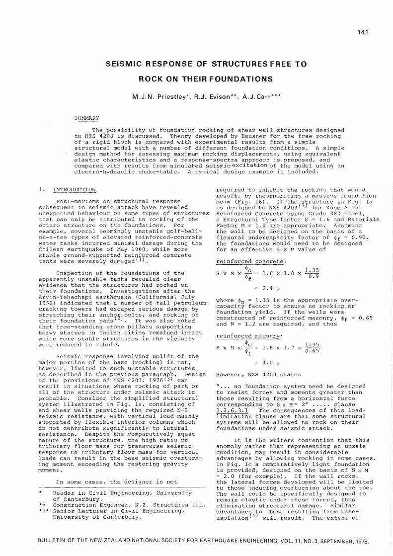
3.1 Shake-Table Facility
The shake-table used for the tests is
a 1.5 m square Aluminium table running on 100 mm diameter steel guides through Glacier DU-PTFE bearings. Drive is provided by a horizontal double-acting 50 kN hydraulic jack powered by a 7 5 litre/min p u m p , and controlled by an MTS servo-hydraulic electronic controller. This enables the table to be driven horizontally in a number of modes ranging from simple sinusoidal motion, using a function generator as signal source, to simulated seismic ground motion using an FM tape recorder with a suitable scaled earthquake record as signal source.
3.2 Rocking Model
Dimensions of the model were dictated by the size and capacity of the shake-table. A simple one-sixth scale simulation of a concrete masonry shear-wall structure with prototype pre-rocking fundamental period of 0.4 sec was adopted. Fig. 5 shows relevant dimensions of the m o d e l , which was designed to have a model natural period of about 0.067 sec, satisfying Cauchy similitude and was proportioned so that rocking would initiate at a response acceleration of 0.34 g. Although this would imply prototype rocking at an unrealistically low response acceleration of 0.057 g, it enabled extensive examination of the rocking phenomenon at comparatively low levels of earthquake excitation, and resulted in a model of convenient dimensions. Structural form of the model was chosen to give the required characteristics, rather than geometric similitude.
To ensure even reaction of the model dead weight, it was supported on four circular discs of adjustable h e i g h t , with thin insertion-rubber pads glued to the bottom of the discs to prevent damage to the table surface on impact during rocking. Three main foundation conditions were investigated :
(a) Model supported directly on table, (b) model supported on 25 mm layer of hardness IRHD rubber, simulating a deformable foundation material. The design of this pad was such that a three-fold increase in natural no-rocking period resulted. (c) As for (b) but with the four levelling feet removed to provide continuous contact between the model base and rubber pad.
In addition, limited 'free-rocking' tests were carried out in the field, supporting the model on well-compacted clay soil. These different foundation conditions were not designed to model specific realistic v a l u e s , but rather were used to investigate the general significance of foundation compliance on results.
3.3 Tests Performed
Four categories of dynamic test were investigated, namely
1. Natural decay of free vibration at amplitudes less than that required in initiate rocking. This enabled natural no-rocking frequencies and damping to be measured.
2. Natural decay of rocking motion. The model was displaced to an amplitude exceeding

144
that required to cause uplift, and released. Measurements of amplitude of rocking, natural period and rate of decay provided experimental data for comparison with Housner's equations.
3. Sinusoidal Excitation. The model was subjected to forced sinusoidal base acceleration to facilitate the study of response to different frequencies.
4. Simulated seismic excitation. A suitably scaled record of the N-S component of the 1940 El Centro earthquake was used as table excitation. To provide similitude, m o d e l / prototype frequency and acceleration scales of 6.0 were required. The earthquake acceleration record, so scaled, was integrated twice by computer and recorded on analogue magnetic tape as a displacement trace. Scaling of magnitude was provided by attenuation through the MTS Controller/ and the model was subjected to various levels of excitation corresponding to the range 2 0 % to 100% of El Centro 1940 N - S .
Because of space limitations only results of the free-rocking and seismic testing are included in this paper. More complete information is incuded in ref. N o . 11.
3.4 Instrumentation
Model displacements relative to the shake-table were monitored by Hewlett Packard DCDT's , and accelerations were measured by Kyowa AS-10B accelerometers. Instrumentation locations are included in Fig. 5. In addition, table displacement and acceleration were monitored to provide comparison with specified values. Analogue traces of response were recorded on a 25 channel Bryan Southern U-V recorder.
Fig. 6 shows the model under test.
4. EXPERIMENTAL RESULTS
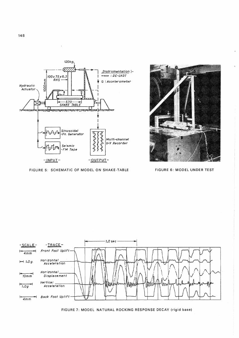
4.1 Natural Decay of Rocking
A typical composite record of free rocking decay is shown for the rigid base condition in Fig. 7. It will be noted that though the vertical displacements at front and back feet do not indicate significant * bounce', high vertical accelerations were induced on impact, which are reflected in significant superimposed accelerations on the horizontal acceleration record. These perturbations at the natural structural frequency do not appear to affect the basic rocking response. It was noticeable that the traces recorded for the flexible base conditions (rubber-pad foundations and soil-base) contained much lower superimposed accelerations from the impacts, as would be expected ( H ) .
From the horizontal displacement records for the four base conditions (e.g. central trace in Fig. 7) the experimental rate of rocking decay, ^n, could be determined as a function of ^o number of impacts, n. The results for all base conditions fell on the same c u r v e , and are compared in Fig. 8a with predictions based on equation ( 5 ) , using a value of r = 0.87. It will be seen that the theoretical decay value is in good agreement with average experimental behaviour. The value of r = 0.87 w a s adopted to provide
a best fit w i t h the experimental data, and is substantially different from the value of r = 0.70 predicted by eqn (4) from the model parameters. It is apparent that the impacts were not totally inelastic, as assumed by Housner, and that a significant proportion of the energy of impact was being returned to the rocking system. It is of interest that the experimental value of r was effectively independent of the foundation condition.
The natural decay displacement traces also provided data for assessing Housner's relationship between frequency and amplitude of rocking, given in eqn (1). Fig. 8b shows the comparison between theory and experimental results for rigid base and rubber-pad base conditions. Agreement is excellent for both base conditions. It will be noted that for the rubber-pad base, maximum rocking frequency is 3.7 H z , corresponding to the natural no-rocking frequency. Above this level, H o u s n e r 1 s theory does not apply.
4.2 Response to El Centro 1940 N-S Excitation
A typical model response to simulated seismic excitations is shown in Fig. 9, which traces time-histories of model accelerations and displacement resulting from 0.6 x El Centro excitation for the rubber-pad base condit.ion. It will be noted that rocking initiates almost immediately in the response record, and continues to the end of the base excitation. Peak response d i s placement occurs at about 1.5 sec (9.0 sec in prototype time-scale) and damps out comparatively rapidly. Vertical accelerations resulting from impact of the feet on the rubber pad are clearly apparent and are reflected in the horizontal acceleration record.
The design approach developed in section 2.3 was used to estimate the peak model response. First model characteristics were converted to equivalent prototype values using the model/prototype relationships :
accelerations : a = L ^ a (9) p r m displacements : A = L a (10)
p r m periods : T = L T (11) p r m where L r = 6 is the prototype/model length ratio, and p and m refer to prototype and model values respectively.
The experimental value of r - 0.87 was adopted, resulting, from Fig. 3, in an equivalent viscous damping of 4.8%. Using an appropriately scaled version of Fig. 8b and the El Centro N-S tripartite response spectra (see Fig. 1 2 ) , results in a prototype displacement of 300 mm after four trial-and-error cycles based on an initial 1 g u e s s 1 of 120 mm displacement. This scales to a predicted maximum model displacement of 50 m m (eqn 10) w h i c h compares with the measured value of 45 mm. This agreement is felt to be acceptable considering the approximations inherant in the analysis.
5. DESIGN EXAMPLE
The experimental results confirm Housner's analysis of rocking behaviour and

145
provide some support for the proposed simplified analysis technique described in section 2. It may be of interest, however, to consider a typical design example and investigate the likely response using the response-spectra analysis.
Consider the N-S response of the five-storey masonry structure shown in Fig. 10. The equivalent weight of beams and slabs is taken as 5.0 kPa, and seismic live-load as 1.67 kPa. Half the total Dead plus Live Load contributes to the seismic shear of each end w a l l , but vertical load for each wall comes only from the wall dead weight plus a 5.0 m wide tributary strip from each floor. Including roof and ground floor, total vertical load is estimated at 4.0 MN/wa l l . For normal seismic analysis, the mass distribution may be replaced by the equivalent No-Rocking 1 F model in Fig. 10, which results in a natural period of T = 0.4 3 sec, based on E m - 5.0 G P a
1 2 .
(1)
The analysis steps are
Will Structure Rock ?
Compare the wall overturning shear with code^ shear. Rocking will occur w h e n the overturning moment exceeds the restoring moment. That is, when
0.900 x 9.81 - x 12.9 > 4.0 MN x 7.0, g
where a is the response acceleration required to induce rocking, and the length of toe in contact with soil is assumed to be 2.0 m, giving a lever arm of the restoring moment of 7.0 m.
.*. a > 0. 245 g (12)
is the requirement for rocking.
Compare with NZS 4 2 0 3 ^ requirements for Zone A, Class III
CSMIR
thus
ie
0.15 x 1.6 x 1.2 x 1.0 x 1.0
Vd = 0.288 W,
a = 0.288 g. (13)
This exceeds the value given in eqn (12) to induce rocking. Note also that the code value is based on dependable flexural strength, using an undercapacity factor <j)f = 0.65. Based on ideal strength, response acceleration will be
0.288 0.65 0.443 g (14)
If overstrength due to strain-hardening etc. develops, an overcapacity factor (J>0 = 1.35 could be appropriate for grade 380 steel. Thus
1.35 x 0.443 g = 0.598 g (15)
Comparing equations (14) and (15) with eqn (12) it is clear that response at design level loading will result in rocking.
For further confirmation of rocking, check the elastic response spectra to ensure elastic response exceeds code requirem e n t s . From Skinner's response spectra* ' using T = 0.43 sec and A = 5% critical, acceleration response = 0.91 g. Thus rocking
is assured.
(2) Rocking Response
For simplicity, assume the total mass contributing to seismic shear to the wall is uniformly distributed over the wall area, rather than concentrated at floor heights. The approximation involved is small. Distributed mass per unit area is then
1200 17.5 x 15.0
2
- 4.57 tonnes/m
from eqn (3) 2
Io = m(Ixx + Iyy) + M R
Now R = y/92 Io = 4.57
+ 7 = 11.4 m ( 1 7 . 5 3 x 15 + 1 5 3 x 17.5)
12
Io
1200 x 130 t.m
209 107 t m 4
Now W = 4.0 MN
From Eqn ( 2 ) ,
P = 4.0 x 10 x 11.4
2.091 x 1 0 8
0.463
Period of Rocking
Inverting eqn ( 1 ) , the relationship between period and amplitude is
- 1 1
T _ 4 cosh (l-9o/a) (16)
N o w a = tan ^ ~ = 0.661 rad.
and 0o = AR / 17.5
where AR is the roof displacement.
Thus eqn (16) reduces to 1 -1 , T = 8.64 cosh (1-0.0864 A )
This relationship is plotted in Fig. 1 1 .
Damping
Substituting into eqn (4) for the energy reduction factor r, gives
(17)
[ 7 1200 x 13 L_ 209 107 - (1 - cos (2 x 37.9°)
0.21
Thus equation (4) predicts a very low value for squat structures such as the example w a l l . However, since the model studies indicated the calculated value for r un d e r estimates the true v a l u e , conservatively adopt r = 0.50, giving, from Fig. e, X = 2 3 % . The trial-and-error approach using the relationship of Fig. 11 and the tripartite response spectra for El Centro N-S 1940 (Fig. 12) results in a centre-of-mass d i s placement of about 80 mm, corresponding to a roof level displacement of 160 mm, occurring for T = 1.6 sec.

146
The extent of rocking indicated by this example is not excessive, but possible damage resulting from twisting of floor slabs and soil yield would need to be balanced against reduced damage to the shear walls, and savings in foundation design. It should be noted that several recorded earthquakes (eg Parkfield 1966 and Pacoima S75W 1971) have more severe spectral response in the long-period region, and could be expected to induce more extensive rocking than El Centro N-S 1940.
6. CONCLUSIONS
(1) The response of a structure free to rock on its foundations offers a means of base-isolation, in that lateral accelerations are limited to the level inducing rocking. Structural damage can be reduced by designing structural elements to remain elastic, at the rocking acceleration.
(2) Housner's equations describing the relationship between frequency and amplitude for a rocking block have been verified for a simple structural m o d e l . Foundation conditions did not have a significant influence on the rocking response. However, H o u s n e r 1 s assumption that rocking impacts would represent inelastic collisions was found to be unconservative.
(3) Extension of H o u s n e r 1 s theory resulted in the development of a simple method for predicting maximum displacement of rocking, by use of displacement response spectra and an equivalent elastic representation of the rocking system. Limited shake-table testing provided reasonable verification of the theory.
(4) The approach developed was intended to provide a means for estimating the rocking response of building structures. Application to other structures, such as bridge piers and chimneys, examples of which have already been designed to rock during earthquakes, is obvious. Non-structural applications , such as rocking of stacked containers, could also be considered.
(5) Verification of the theory has so far been limited to a single model and a single earthquake record. Further research is needed to test the scope of applicablility of the method. In particular, the high equivalent viscous damping predicted for squat rocking structures needs verification.
ACKNOWLEDGEMENTS
The experimental work described in this paper was part of an M . E . project by Evison, supervised by Priestley and Carr. Grateful acknowledgement is made of financial support by Holmes Wood Poole and Johnstone, Consulting Engineers, Christchurch.
REFERENCES
Loadings for Buildings", Pub. S.A.N.Z., Wellington, 1976, 80 pp.
4. Skinner, R. I. and McVerry, G. H., "Base Isolation for Increased Earthquake Resistance of Buildings", B u l l . N . Z . Nat. S o c for E.E., V o l . 8, No. 2, June, 1975, pp 93-101.
5. Bartlett, P. E., "Foundation Rocking on a Clay Soil", M . E . Thesis, Rept. N o . 154, School of Eng., Univ. of Auckland, Nov. 1976, 144 pp.
6. Meek, J. W., "Effects of Foundation Tipping on Dynamic Response", Journal Struct. Div. ASCE Vol. 101, No. ST7 July 1975, pp 1297-1311.
7. Sexton, H. J., Discussion of ref 6. Journ. Struct. Div. ASCE V o l . 102 No ST 6 June 1976, p 1262.
8. Beck, J. L. and Skinner, R. I., "The Seismic Response of a Proposed Reinforced Concrete Railway Viaduct", DSIR Rept No. 369, May 1972, 17 pp.
9. Housner, G. W., "The Behaviour of Inverted Pendulum Structures During Earthquakes", Bull. Seis. Soc. of Am., V o l . 53, No. 2, Feb. 1963, pp 403-417.
10. Kelly, J. M. and Tsztoo, D . F., "Earthquake Simulation Testing of a Stepping Frame with Energy-Absorbing Devices". Bull. N . Z . Nat. Soc. for E.E., V o l . 10, No. 4, Dec. 1977 pp 196-207.
11. Evison, R. J. , "Rocking Foundations", M . E . Thesis, Dept. Civil Eng., Res. Rept. No. 77-8, University of Canterbury, Feb. 1977, 96 pp.
12. Priestley, M.J.N., "Seismic Resistance of Reinforced Concrete Masonry Shear Walls with High Steel Percentages", Bull. N . Z . Nat. Soc. E.E., Vol. 10, No. 1, March, 1977. pp 1-16.
13. Skinner, R. I., "Handbook for E a r t h q u a k e -Generated Forces and Movements in Tall Buildings",N.Z. DSIR Bull. No. 166, 1964.
Paper received 7 August, 1978.
1. Cloud, W. K., "Period Measurements of Structures in Chile", Bull. Seismological Society of America. V o l . 53 No. 2, Feb. 1963, pp 359-379.
2. Housner, G. W., "Limit Design of Structures to Resist Earthquakes", Proc. 3rd World Conf. on Earthquake Eng. 1956, pp 5.1-5.13.
3. S.A.N.Z., "NZS 4203: Code of Practice for General Structural Design and Design

147
N t
f l o o r a r e a c o n t r i b u t i n g t o s e i s m i c l a t e r a l l o a d , N - S
( a ) F l o o r P l a n : D i s t r i b u t i o n o f F l o o r L o a d s
( b ) H e a v y F o u n d a t i o n B e a m ( c ) L i g h t F o u n d a t i o n B e a m
- D u c t i l e R e s p o n s e - R o c k i n g R e s p o n s e
FIGURE 1: A L T E R N A T I V E P H I L O S O P H I E S FOR S E I S M I C R E S P O N S E OF CANTILEVER SHEAR W A L L S
E n e r g y R e d u c t i o n F a c t o r , r.
FIGURE 3 : A P P R O X I M A T E R E L A T I O N S H I P B E T W E E N E Q U I V A L E N T V I S C O U S D A M P I N G A N D ENERGY R E D U C T I O N FACTOR
FIGURE 2 : H O U S N E R ' S R O C K I N G B L O C K S
T, \ P e r i o d
{ b ) T R I P A R T I T E R E S P O N S E S P E C T R A
FIGURE 4 : E S T I M A T E OF M A X I M U M D I S P L A C E M E N T F R O M R E S P O N S E SPECTRA
148
FIGURE 5: SCHEMATIC OF MODEL ON SHAKE-TABLE FIGURE 6: MODEL UNDER TEST
FIGURE 7: MODEL NATURAL ROCKING RESPONSE DECAY ( r i g i d base)

149
T h e o r y r = O. 8 7
Exp . r i g i d base
Exp. r u b b e r pad
E x p . s o i l base
4 8 12 16 No. o f I m p a c t s ( n )
( a ) DECAY O F R O C K I N G
2 0
10
a 4
cr 0)
\
N o - r o c k i n g f r e q . f o r r u b b e r pad
T h e o r y ( f - l ousner )
Exp . r i g i d b a s e
E x p . r u b b e r p a d
16 24 3 2 H o r i z o n t a l D i s p l a c e m e n t ( m m )
( b ) F R E Q U E N C Y v s A M P L I T U D E
FIGURE 8: THEORY vs. EXPERIMENT FOR MODEL
FIGURE 9: MODEL RESPONSE TO 0.6 x EL CENTRO 1940 N-S (rubber pad + feet)

150
S h e a r W a i f s
E l e v a t i o n
I m " ~ m m m m — • N A
„ 1 9 0 m m • 1 1
s
3 0 m
T y p i c a l F l o o r P l a n
W a l l E l e v a t i o n
» 1 0 0 t
> 2 0 0 t
> 2 0 0 t
> 2 0 0 t
> 2 0 0 t
* . 4 s y 3 0 0 t
W a l l M a s s e s f o r
N-S E x c i t a t i o n
9 0 0 t
N o - R o c k i n g 1*F M o d e l
FIGURE 10: SIMPLIFIED M A S O N R Y BUILDING FOR DESIGN EXAMPLE
cn c
o or
o
0 2 5 0 5 0 0 7 5 0 1 0 0 0 Roof L e v e l D i s p l a c e m e n t ( m m )
FIGURE 11: ROCKING CHARACTERISTICS OF EXAMPLE STRUCTURE
D A M P I N G V A L U E S A R E 0. 2. 5. 10 A N D 20 PERCENT OF C R I T I C A L
.04 .06 .08 .1 .4 £ 3 1
PERIOD (sees) 4 6 8 10 20
FIGURE 12: TRIPARTITE RESPONSE SPECTRA, EL CENTRO 1 9 4 0 N-S