rocking seismic isolation of bridges supported by direct...
TRANSCRIPT
Rocking Seismic Isolation of Bridges Supported by Direct Foundations
Kazuhiko KawashimaTokyo Institute of Technology
Caltrans-PEER Seismic Research SeminarSacramento, CA, USA
June 8, 2009

Requirements in the OverturningBased on Static Analysis
aB e
VMe <=
Eccentricity
⎩⎨⎧=
6/3/
ll
ea
Allowable Eccentricity
Static
Static+Seismic
Bearing Capacity
aB q
lbM
lbVq <+= 2max
6
el
V
bmaxq
BM
Eccentricity
Size effect is not included in the conventional static analysis
As long as the shape and mass density are the same, a foundation can overturn in the conventional static analysis no matter how the foundation is extremely large
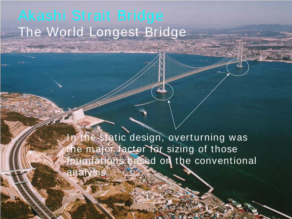
Akashi Strait BridgeThe World Longest Bridge
In the static design, overturning was the major factor for sizing of those foundations based on the conventional analysis
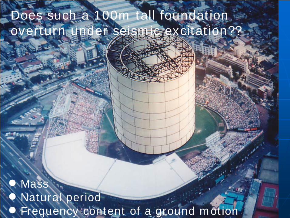
Does such a 100m tall foundation overturn under seismic excitation??
MassNatural periodFrequency content of a ground motion

0.6m
0.2m
0.4m
1.0
Geometrical scale
Kawashima & Unjoh (1992)
0.33m
1m
0.66m
1.65
m=579kg
1.5m
0.5m
0.75m
2.5
m=1452kgm=139kgMass
Shake Table Experiment on the Effect of Size & Mass for Overturning of Rigid Foundations
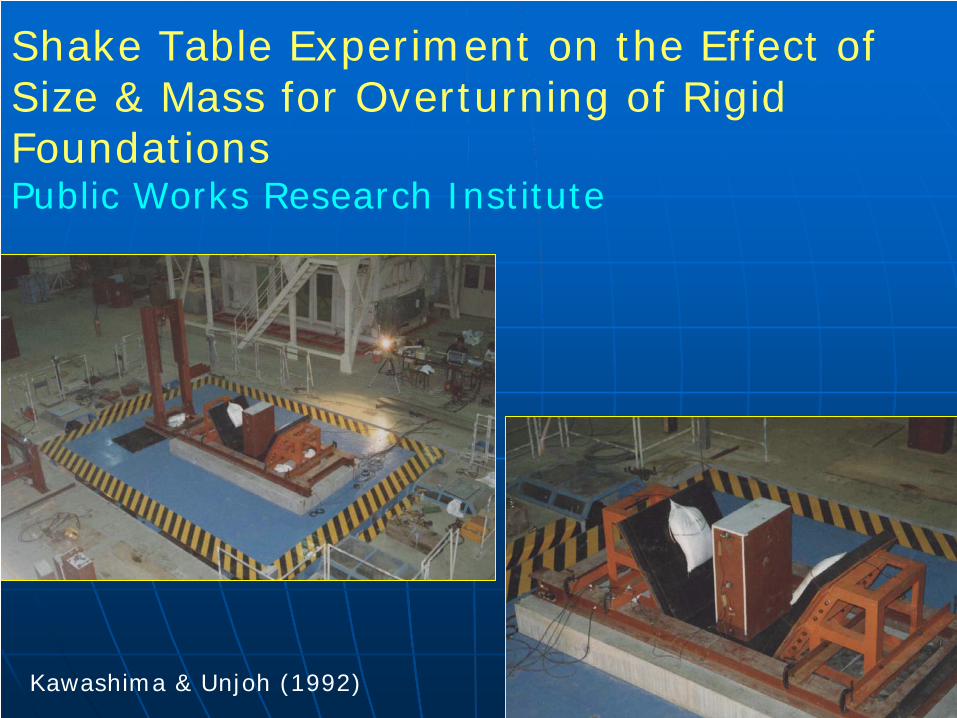
Shake Table Experiment on the Effect of Size & Mass for Overturning of Rigid FoundationsPublic Works Research Institute
Kawashima & Unjoh (1992)
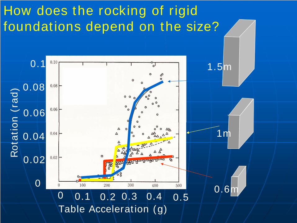
0 0.2 0.40.3
0.02
0.06
0.04
0.08
0
0.1
Rota
tion (
rad)
0.1 0.5Table Acceleration (g)
0.6m
1m
1.5m
How does the rocking of rigid foundations depend on the size?
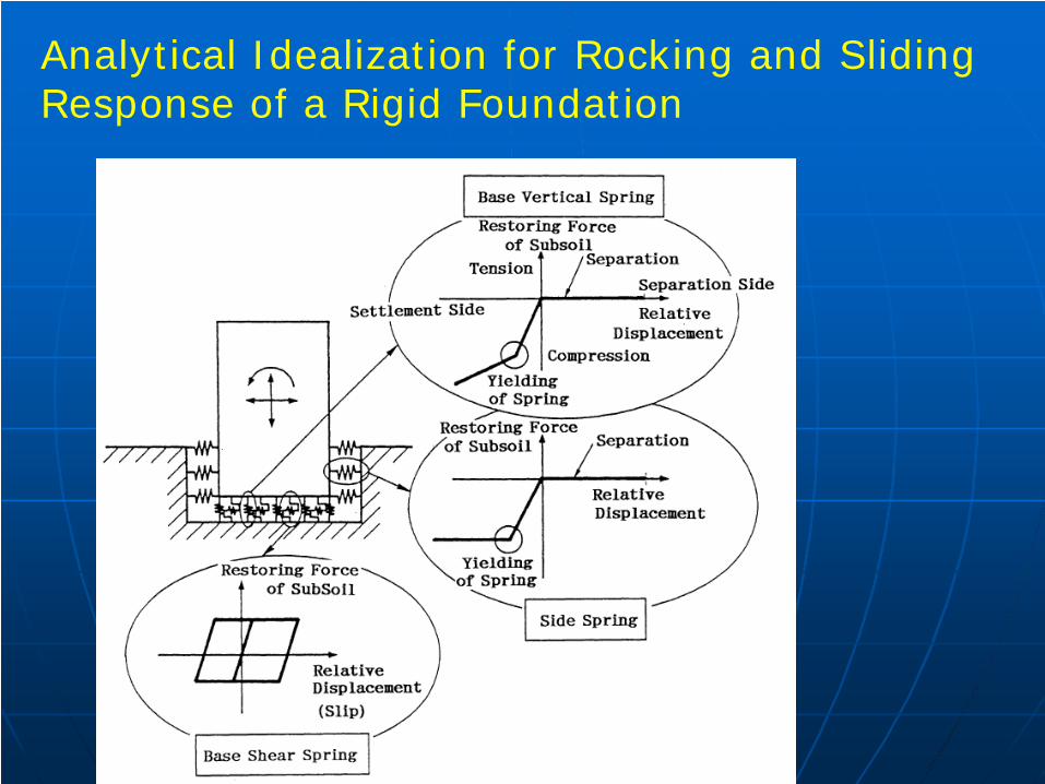
Analytical Idealization for Rocking and Sliding Response of a Rigid Foundation
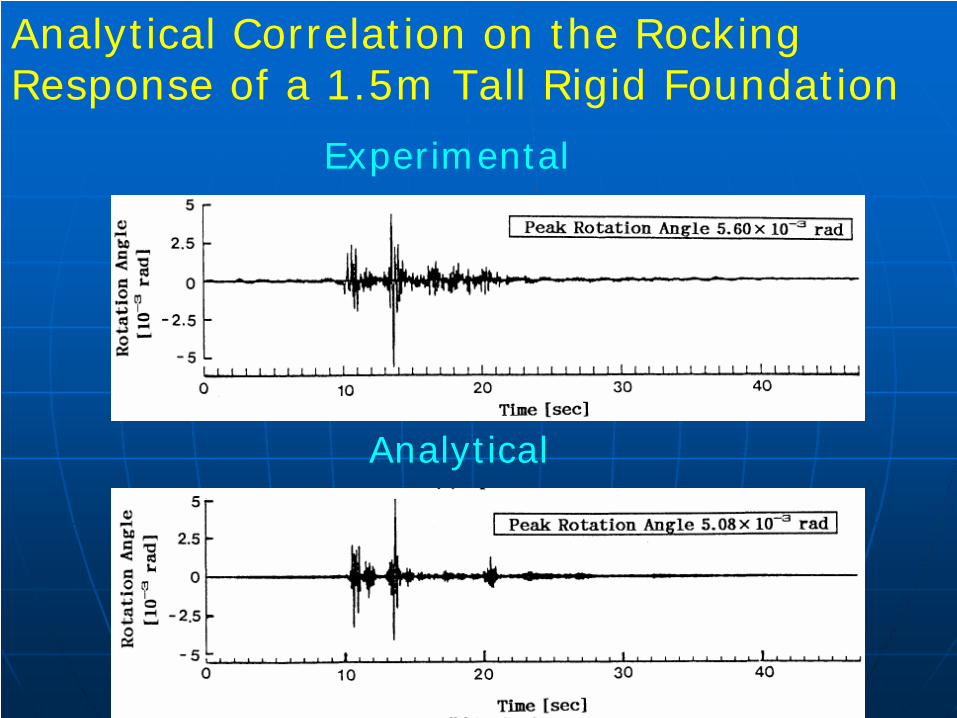
Analytical Correlation on the Rocking Response of a 1.5m Tall Rigid Foundation
Experimental
Analytical
Kawashima et al (1994)
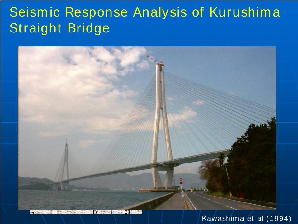
Seismic Response Analysis of Kurushima Straight Bridge
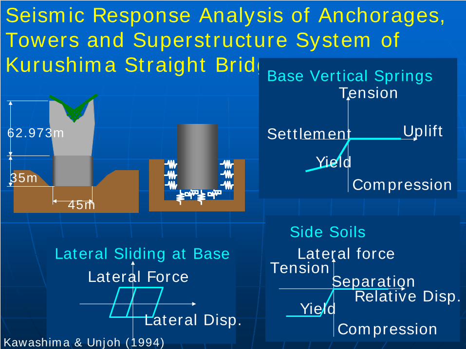
62.973m
35m
45m
Seismic Response Analysis of Anchorages, Towers and Superstructure System of Kurushima Straight Bridge
Separation
Lateral forceTension
CompressionYield
Side Soils
Relative Disp.Lateral Force
Lateral Disp.
Lateral Sliding at Base
Kawashima & Unjoh (1994)
Uplift
Compression
Tension
Settlement
Base Vertical Springs
Yield
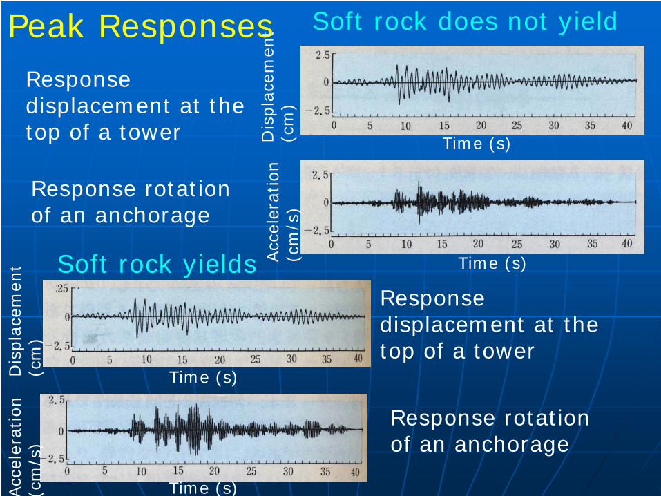
Peak Responses
Dis
pla
cem
ent
(cm
)
Time (s)
Response displacement at the top of a tower
Soft rock does not yield
Acc
eler
atio
n
(cm
/s)
Time (s)
Response rotation of an anchorage
Soft rock yields
Dis
pla
cem
ent
(cm
)
Time (s)
Response displacement at the top of a tower
Time (s)Acc
eler
atio
n
(cm
/s)
Response rotation of an anchorage
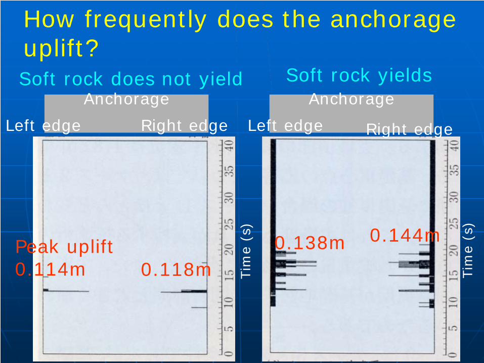
Anchorage
How frequently does the anchorage uplift?
Tim
e (s
)
Left edge Right edge
Tim
e (s
)
AnchorageSoft rock yields
Left edge Right edge
Soft rock does not yield
Peak uplift 0.114m 0.118m
0.138m 0.144m
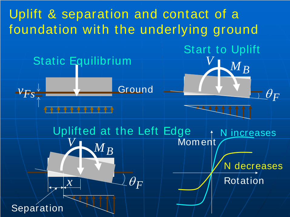
Uplift & separation and contact of a foundation with the underlying ground
Static Equilibrium
Fsv Ground
Start to Uplift
Fθ
BMV
Uplifted at the Left Edge
Fθ
BMV
x
Separation
N increases
N decreases
Rotation
Moment
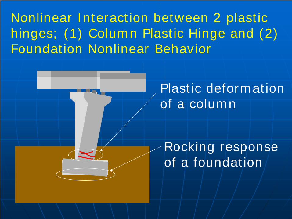
Nonlinear Interaction between 2 plastic hinges; (1) Column Plastic Hinge and (2) Foundation Nonlinear Behavior
Rocking response of a foundation
Plastic deformation of a column
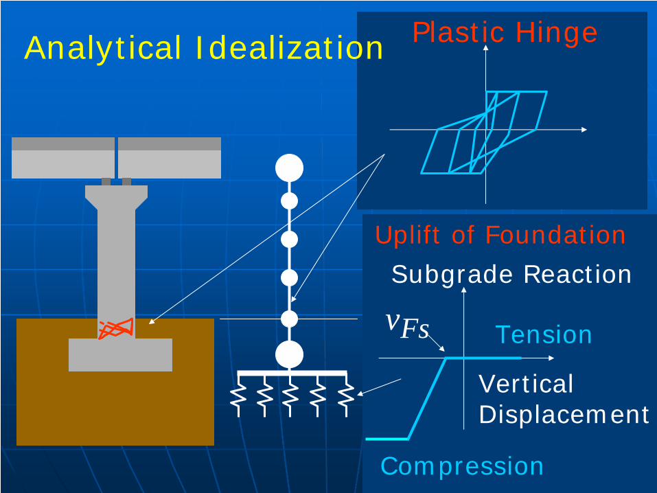
Plastic HingeAnalytical Idealization
Vertical Displacement
Subgrade Reaction
Compression
Tension
Uplift of Foundation
Fsv
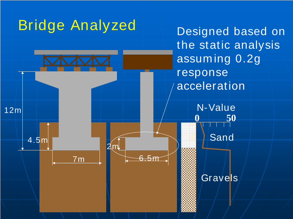
4.5m
12m
7m
2m6.5m
N-Value500
Sand
Gravels
Bridge Analyzed Designed based on the static analysis assuming 0.2g response acceleration
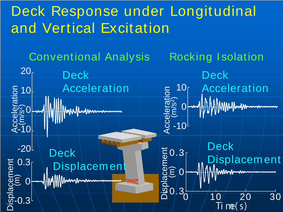
Deck Response under Longitudinal and Vertical Excitation
Rocking Isolation
-0.3
0
0.3
0 10 20 30Dis
plac
emen
t (m
)
Ti me( s)
Deck Displacement
-10
0
10
Acc
eler
atio
n (m
/s2 )
Deck Acceleration
Conventional Analysis
-0.3
0
0.3
Dis
plac
emen
t (m
)
DeckDisplacement
-20
-10
0
10
20
Acc
eler
atio
n (m
/s2 )
Deck Acceleration
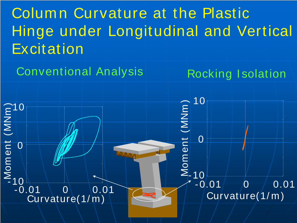
-0.01 0 0.01
Mom
ent
(MN
m)
Curvature(1/m)
10
-10
0
-0.01 0 0.01M
om
ent
(MN
m)
Curvature(1/m)
10
-10
0
Column Curvature at the Plastic Hinge under Longitudinal and Vertical ExcitationConventional Analysis Rocking Isolation
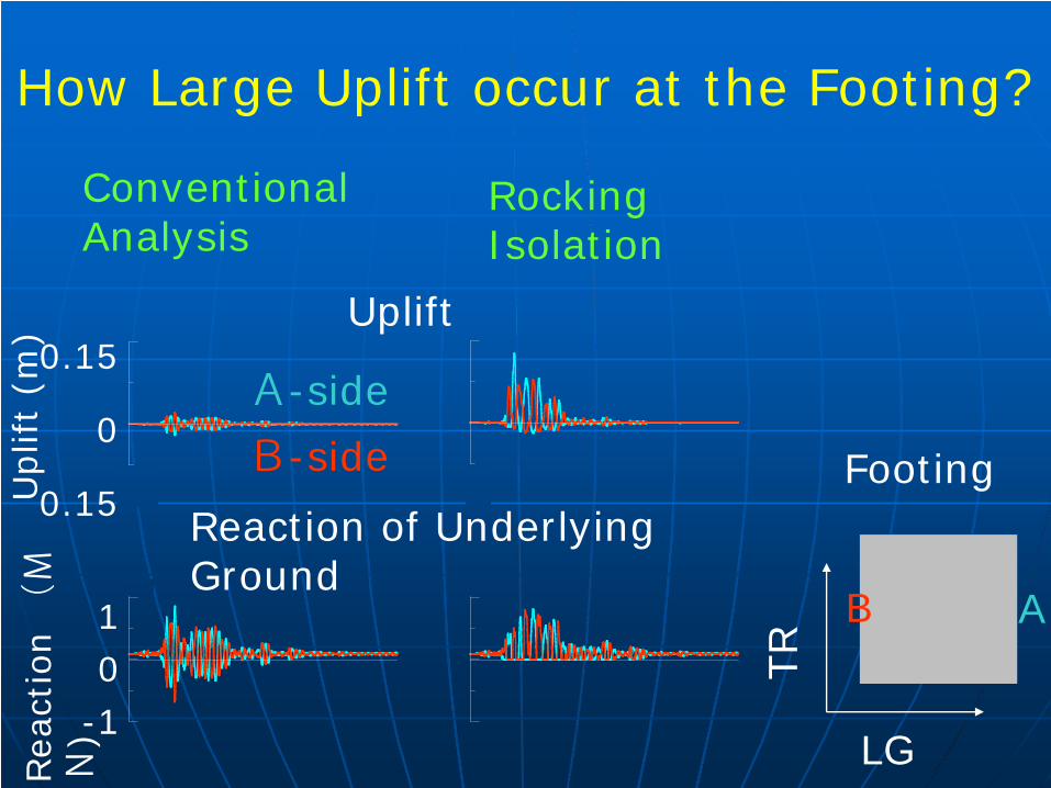
How Large Uplift occur at the Footing?
Uplift
Reaction of Underlying Ground
B A
Rea
ctio
n (M
N)
10
-1
Footing
LGTR
Uplif
t (m
)
0.15
0
0.15
A-side
B-side
Conventional Analysis
Rocking Isolation
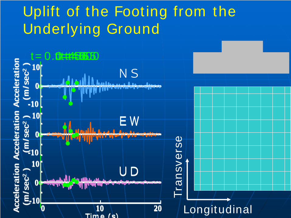
t=5.0t=6.0
Time (s)0 10 20
Acc
eler
atio
n
(m/s
ec2
)
NS
EW
UD
Acc
eler
atio
n
(m/s
ec2
)Acc
eler
atio
n
(m/s
ec2
)
-10
0
10-10
0
10-10
0
10t=0.0
Time (s)0 10 20
Acc
eler
atio
n
(m/s
ec2
)
EW
UD
Acc
eler
atio
n
(m/s
ec2
)Acc
eler
atio
n
(m/s
ec2
)
-10
0
10-10
0
10-10
0
10t=4.0t=4.5t=5.5
Longitudinal
Tra
nsv
erse
Uplift of the Footing from the Underlying Ground
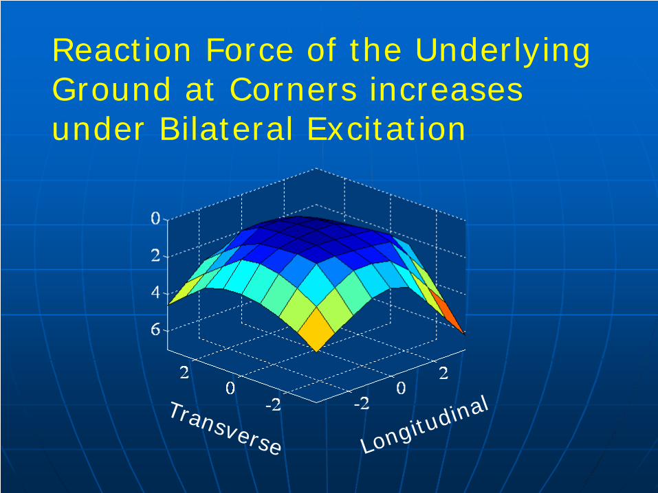
Reaction Force of the Underlying Ground at Corners increases under Bilateral Excitation
LongitudinalTransverse
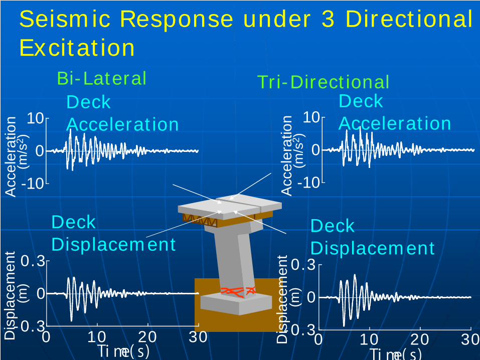
Bi-Lateral Tri-Directional
-0.3
0
0.3
0 10 20 30Dis
plac
emen
t (m
)
Ti me( s)
Deck Displacement
-10
0
10
Acc
eler
atio
n (m
/s2 )
Deck Acceleration
-0.3
0
0.3
0 10 20 30Dis
plac
emen
t (m
)
Ti me( s)
Deck Displacement
Seismic Response under 3 Directional Excitation
-10
0
10
Acc
eler
atio
n (m
/s2 )
Deck Acceleration
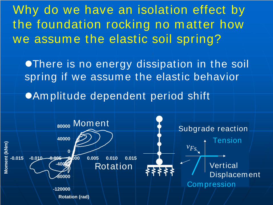
-120000
-80000
-40000
0
40000
80000
-0.015 -0.010 -0.005 0.000 0.005 0.010 0.015
Rotation (rad)
Mom
ent (
kNm
)
Moment
Rotation Vertical Displacement
Subgrade reaction
Compression
TensionFsv
Why do we have an isolation effect by the foundation rocking no matter how we assume the elastic soil spring?
There is no energy dissipation in the soil spring if we assume the elastic behavior
Amplitude dependent period shift
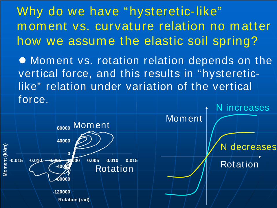
-120000
-80000
-40000
0
40000
80000
-0.015 -0.010 -0.005 0.000 0.005 0.010 0.015
Rotation (rad)
Mom
ent (
kNm
)
Moment
Rotation
Why do we have “hysteretic-like” moment vs. curvature relation no matter how we assume the elastic soil spring?
Moment vs. rotation relation depends on the vertical force, and this results in “hysteretic-like” relation under variation of the vertical force.
N increases
N decreases
Rotation
Moment
Factors which contribute to the energy dissipation of a foundation during rocking response
Nonlinear soil behavior around a foundation (nonlinearity of soils, yield of bearing capacity, sliding & slip, etc)
Energy dissipation due to pounding of the footing to the underlying ground
Radiational damping
…
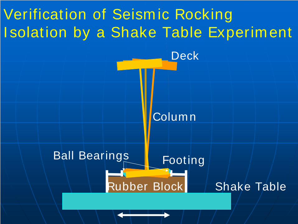
Deck
Column
FootingBall Bearings
Rubber Block Shake Table
Verification of Seismic Rocking Isolation by a Shake Table Experiment
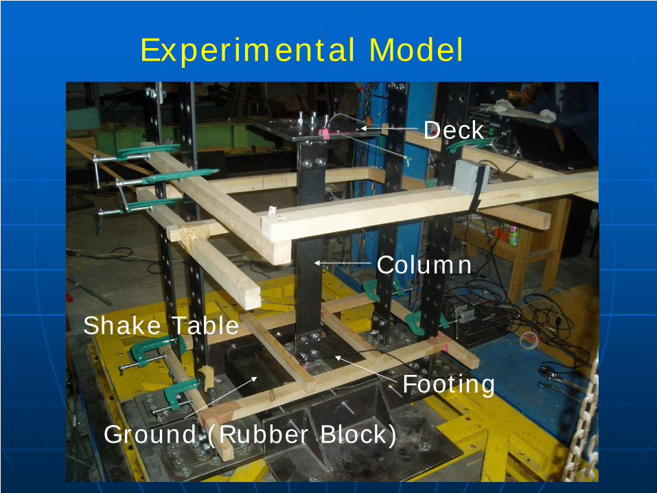
Experimental Model
Deck
Column
Footing
Ground (Rubber Block)
Shake Table
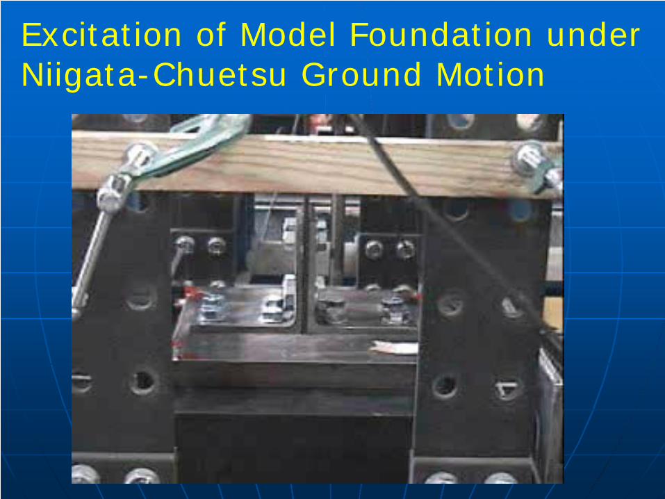
Excitation of Model Foundation under Niigata-Chuetsu Ground Motion
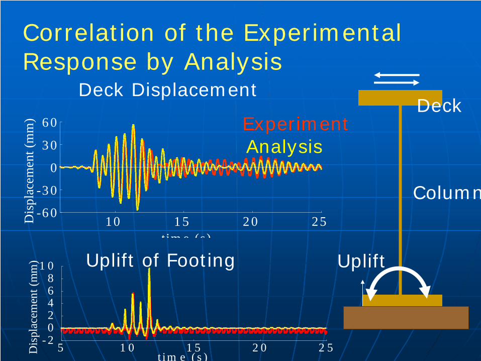
Correlation of the Experimental Response by Analysis
Deck
Column
Uplift
- 202468
1 0
5 1 0 1 5 2 0 2 5Dis
plac
emen
t (m
m)
t im e ( s )
Uplift of Footing
-6 0
-3 0
0
3 0
6 0
10 1 5 2 0 25Dis
plac
emen
t (m
m)
t im e (s)
Deck Displacement
AnalysisExperiment
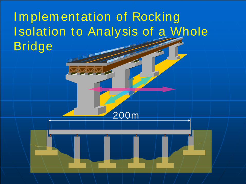
Implementation of Rocking Isolation to Analysis of a Whole Bridge
200m
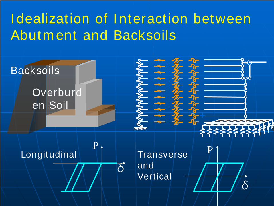
Overburd en Soil
Backsoils
+
Idealization of Interaction between Abutment and Backsoils
δ
PLongitudinal P
δ
Transverse and Vertical
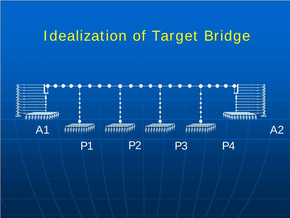
A1 A2P1 P2 P3 P4
Idealization of Target Bridge
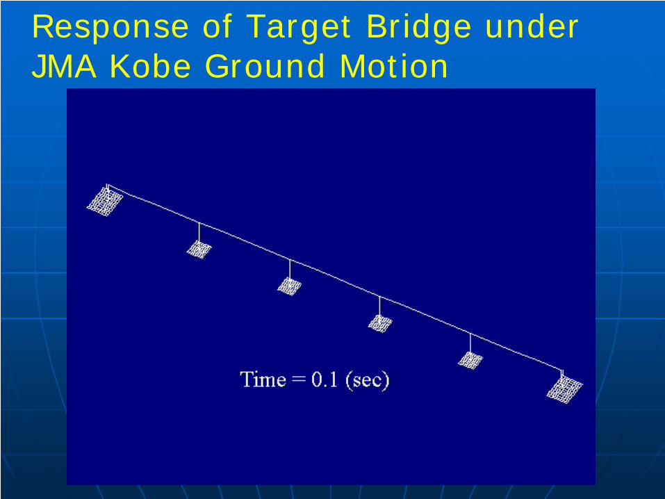
Response of Target Bridge under JMA Kobe Ground Motion
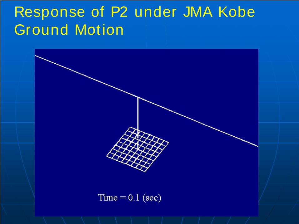
Response of P2 under JMA Kobe Ground Motion
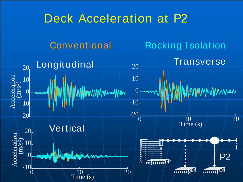
The acceleration at the deck Deck Acceleration at P2
-20
-10
0
10
20
Acc
eler
atio
n (m
/s2 )
Longitudinal
-10
0
10
20
0 10 20
Acc
eler
atio
n (m
/s2 )
Time (s)
Vertical
-20
-10
0
10
20
0 10 20Time (s)
Transverse
Conventional Rocking Isolation
P2
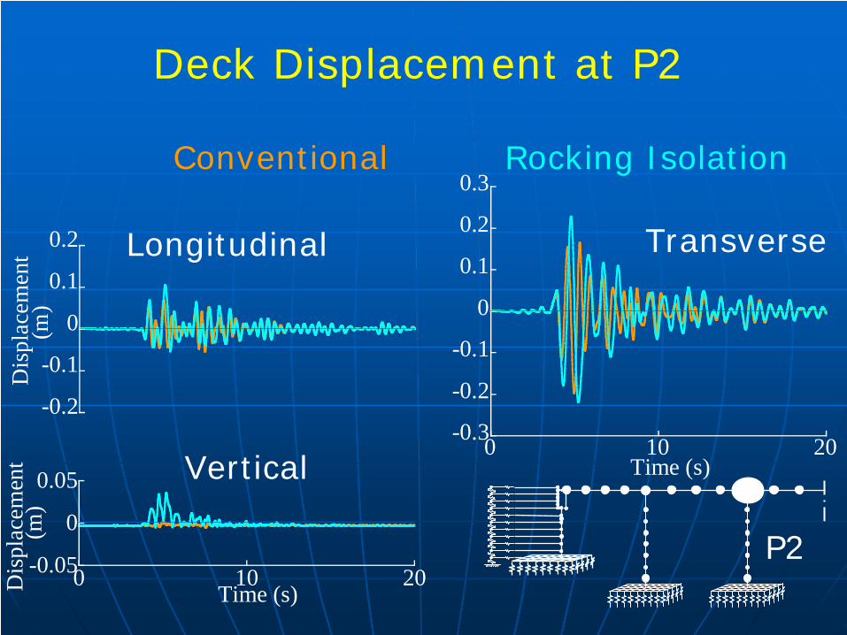
Deck Displacement at P2
-0.2
-0.1
0
0.1
0.2
Dis
plac
emen
t(m
)
Longitudinal
Conventional Rocking Isolation
-0.3
-0.2
-0.1
0
0.1
0.2
0.3
0 10 20Time (s)
Transverse
-0.05
0
0.05
0 10 20Dis
plac
emen
t(m
)
Time (s)
Vertical
P2
-0.2 0 0.2-300
-150
0
150
300
Rea
ctio
n Fo
rce
(kN
)
Displacement (m)
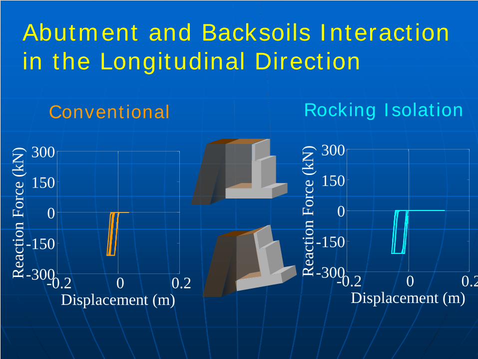
Abutment and Backsoils Interaction in the Longitudinal Direction
Conventional
-0.2 0 0.2-300
-150
0
150
300
Rea
ctio
n Fo
rce
(kN
)Displacement (m)
Rocking Isolation
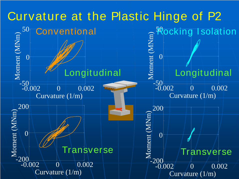
-0.002 0 0.002
Mom
ent (
MN
m)
Curvature (1/m)
50
-50
0
Longitudinal
Curvature at the Plastic Hinge of P2Conventional
-0.002 0 0.002
Mom
ent (
MN
m)
Curvature (1/m)
200
-200
0
Transverse
-0.002 0 0.002
Mom
ent (
MN
m)
Curvature (1/m)
200
-200
0
Transverse
-0.002 0 0.002
Mom
ent (
MN
m)
Curvature (1/m)
50
-50
0
Longitudinal
Rocking Isolation
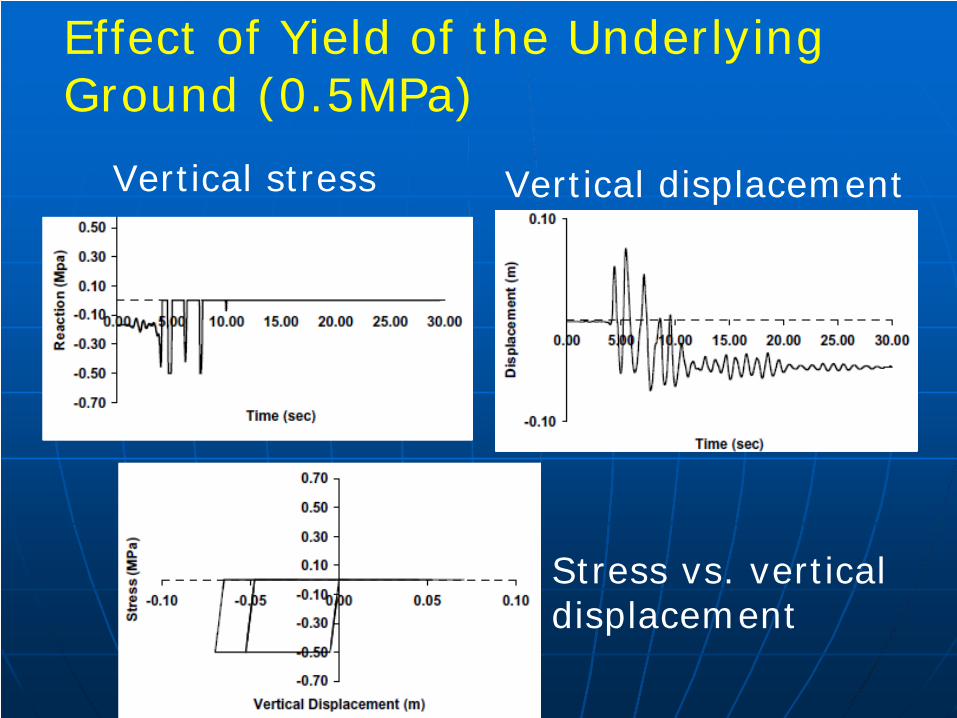
Effect of Yield of the Underlying Ground (0.5MPa)
Stress vs. vertical displacement
Vertical displacementVertical stress
ConclusionsWhen separation of a footing from the
underlying ground due to rocking response is included in analysis, the plastic deformation of a column significantly decreases as a result of softening of the moment vs. rotation hysteresis of the footing.
If the underlying ground yields, it enhances the effect of rocking isolation, however it increases the deck response displacement and it can result in residual drift.
Bridge response acceleration decreases under the seismic rocking isolation, however bridge response displacement increases.
Kawashima, K., Unjoh, S. and Shimizu, H.: Analysis of rocking vibration of rigid foundations, Proc. 8th US-Japan Bridge Workshopn, Panel on Wind & Seismic Effects, UJNR, Chicago, USA, pp. 3-17, 1992
Kawashima, K., Unjoh, S., Shimizu, H. and Mukai, H.: Analytical method of seismic rocking response of a rigid foundation considering the response of superstructure, Journal of Civil Engineering, Vol. 36, No. 2, pp. 42-36, 1994
Kawashima, K. and Hosoiri, K.: Rocking response of bridge columns on direct foundation, Proc. Fib-Symposium, Concrete structures in seismic region, Paper No. 118 (CD-ROM), Athens, 2003
Mergos, P. E., and Kawashima, K.: Rocking isolation of a typical bridge pier on spread foundation, Journal of Earthquake Engineering, Vol. 9, Special Issue 2, pp. 395-414, 2005
Sakellaraki, D. and Kawashima, K.: Effectiveness of seismic rocking isolation of bridges based on shake table test, First European Conference on Earthquake engineering and Seismology, Paper No. 364, pp. 1-10, Geneva, Switzerland, 2006
Related publications

Thank you for your kind attention.