seismic design manual - kineticsnoise.comkineticsnoise.com/seismic/design/p/p6 - roof top equipment...
TRANSCRIPT
DUBLIN, OHIO, USA • MISSISSAUGA, ONTARIO, CANADA
Toll Free (USA only): International: Fax: World Wide Web: Email:
800-959-1229 614-889-0480 614-889-0540 www.kineticsnoise.com [email protected]
PAGE:
P6.0
TABLE OF CONTENTS (Chapter P6) ESR / KSR / KSCR SERIES RESTRAINTS RELEASE DATE: 6/09/04
TABLE OF CONTENTS ESR / KSR / KSCR ROOF TOP EQUIPMENT RATED CURBS General Description P6.1 Submittal Data ESR Submittal Data P6.2.1 KSR Submittal Data P6.2.2 KSCR Submittal Data P6.2.3 Selection Information P6.3 Load Spreader Plate Data P6.4 Installation Instructions P6.5
Kinetics Noise Control © 2003
KIN
ET
ICS
™ S
eism
ic D
esig
n M
anua
l
MEMBER
DUBLIN, OHIO, USA • MISSISSAUGA, ONTARIO, CANADA
Toll Free (USA only): International: Fax: World Wide Web: Email:
800-959-1229 614-889-0480 614-889-0540 www.kineticsnoise.com [email protected]
DOCUMENT:
P6.1
ESR ISOLATION CURB DESCRIPTION AND SPECIFICATION PAGE 1 OF 5 RELEASE DATE: 11/26/03
Kinetics Noise Control © 2003
KIN
ET
ICS
™ S
eism
ic D
esig
n M
anua
l
MEMBER
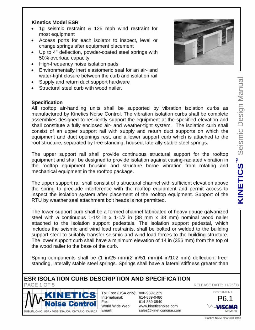
Kinetics Model ESR • 1g seismic restraint & 125 mph wind restraint for
most equipment • Access ports for each isolator to inspect, level or
change springs after equipment placement • Up to 4" deflection, powder-coated steel springs with
50% overload capacity • High-frequency noise isolation pads • Environmentally inert elastomeric seal for an air- and
water-tight closure between the curb and isolation rail• Supply and return duct support hardware • Structural steel curb with wood nailer.
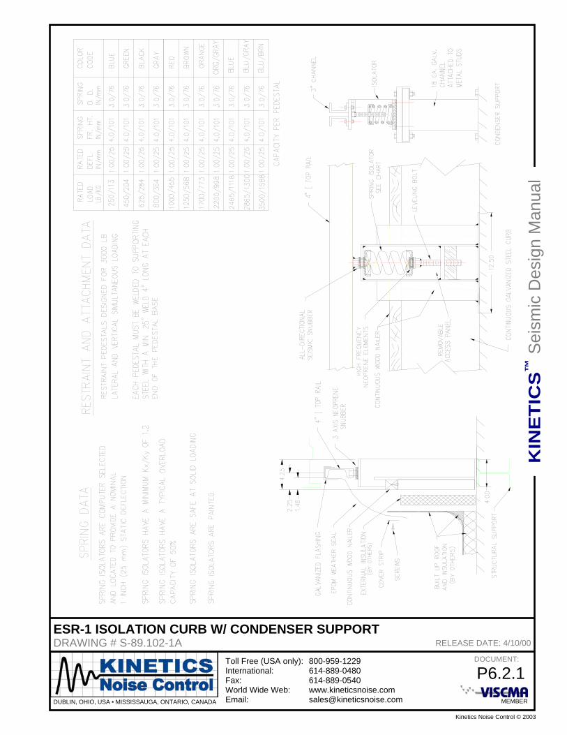
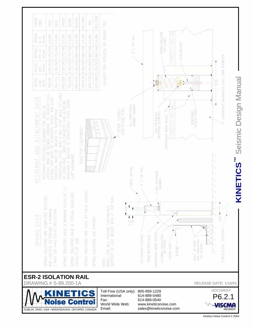
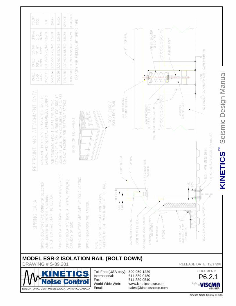
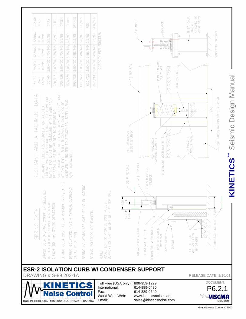
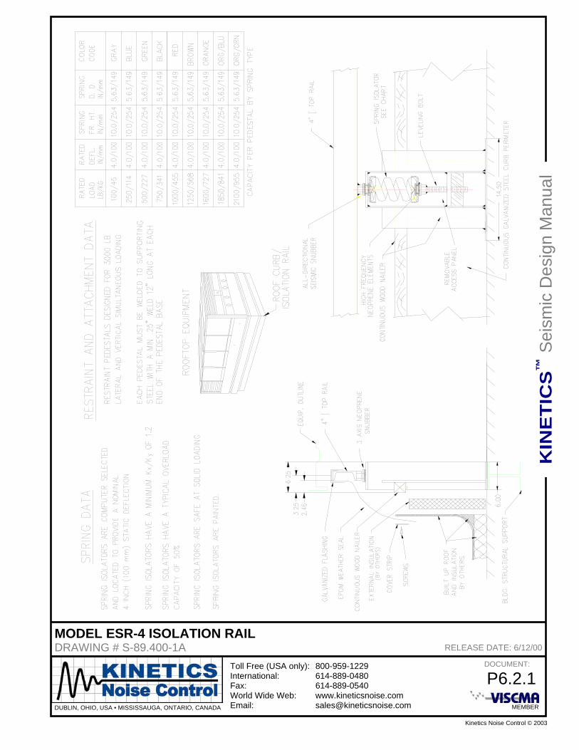
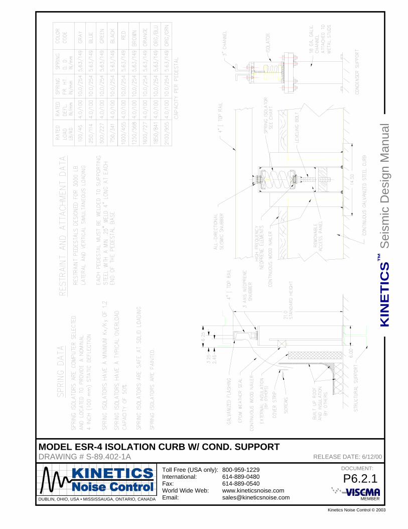
Specification All rooftop air-handling units shall be supported by vibration isolation curbs asmanufactured by Kinetics Noise Control. The vibration isolation curbs shall be completeassemblies designed to resiliently support the equipment at the specified elevation andshall constitute a fully enclosed air- and weather-tight system. The isolation curb shallconsist of an upper support rail with supply and return duct supports on which theequipment and duct openings rest, and a lower support curb which is attached to theroof structure, separated by free-standing, housed, laterally stable steel springs. The upper support rail shall provide continuous structural support for the rooftopequipment and shall be designed to provide isolation against casing-radiated vibration inthe rooftop equipment housing and structure borne vibration from rotating andmechanical equipment in the rooftop package. The upper support rail shall consist of a structural channel with sufficient elevation abovethe spring to preclude interference with the rooftop equipment and permit access toinspect the isolation system after placement of the rooftop equipment. Support of theRTU by weather seal attachment bolt heads is not permitted. The lower support curb shall be a formed channel fabricated of heavy gauge galvanizedsteel with a continuous 1-1/2 in x 1-1/2 in (38 mm x 38 mm) nominal wood nailerattached to the isolation support pedestals. The isolation support pedestal, whichincludes the seismic and wind load restraints, shall be bolted or welded to the buildingsupport steel to suitably transfer seismic and wind load forces to the building structure.The lower support curb shall have a minimum elevation of 14 in (356 mm) from the top ofthe wood nailer to the base of the curb. Spring components shall be (1 in/25 mm)(2 in/51 mm)(4 in/102 mm) deflection, free-standing, laterally stable steel springs. Springs shall have a lateral stiffness greater than
DUBLIN, OHIO, USA • MISSISSAUGA, ONTARIO, CANADA
Toll Free (USA only): International: Fax: World Wide Web: Email:
800-959-1229 614-889-0480 614-889-0540 www.kineticsnoise.com [email protected]
DOCUMENT:
P6.1
ESR ISOLATION CURB DESCRIPTION AND SPECIFICATION PAGE 2 OF 5 RELEASE DATE: 11/26/03
Kinetics Noise Control © 2003
KIN
ET
ICS
™ S
eism
ic D
esig
n M
anua
l
MEMBER
1.2 times the rated vertical stiffness and shall be designed for a typical 50% overload tosolid. All springs shall have an epoxy-based, powder-coated finish and be color coded toindicate load capacity. Spring coils shall rest on minimum 0.25 in (6 mm) neoprene noisepads. Seismic and wind load restraints shall be designed to limit movement in all directions.Restraint components shall include neoprene snubbers at all contact points for energyabsorption. There shall be no metal-to-metal contact. The isolation curb shall bedesigned to withstand horizontal wind loads of 125 mph (200 km/h) and seismic forces of1g. The vibration isolation curb shall be air and weather tight using an elastomeric seal,which is attached to the upper support frame with a galvanized steel clip. The seal shallextend down past the wood nailer of the lower support assembly and flash over the roofmaterial at the wood nailer on the lower support curb. The seal shall be Class A, astested in accordance with approved Underwriter’s Laboratories, Inc., provisions. Metal orcombination metal and elastomer seals are not permitted. The seal may not bepenetrated for isolator adjustment. The isolation curb system shall be complete with cross-bracing, as required, as a part ofthe upper and lower assemblies. Supply and return flex connector support hardware shallbe supplied for installation by the contractor in the field. The supports will be clearlymarked and dimensioned on the submittal and installation drawings. The supporthardware shall be cut-to-length, galvanized steel channels supported and connected withstamped and punched galvanized steel duct support hangers. The support hangers shallallow the support elevation to be equal to or lower than the equipment rail elevation.Supply air and return duct shall be flexibly attached by the contractor to preventtransmission of vibration to the building structure. Airborne noise control packages, if required, shall be supported by the roof structurewithin the curb and shall have no rigid contact with the isolation curb. The isolation curbassemblies shall be shipped to the job site with the upper support rail, lower support curb,springs, and restraints completely assembled. The contractor shall be required toassemble the four corners, attach the curb to the roof structure, install cross-bracing andflex connector supports as necessary, and install and attach rooftop equipment. Vibration isolators shall be selected by the manufacturer for each specific application tocomply with deflection requirements as shown on the Vibration Isolation Schedule or asindicated on the project documents.
DUBLIN, OHIO, USA • MISSISSAUGA, ONTARIO, CANADA
Toll Free (USA only): International: Fax: World Wide Web: Email:
800-959-1229 614-889-0480 614-889-0540 www.kineticsnoise.com [email protected]
DOCUMENT:
P6.1
KSCR ISOLATION CURB DESCRIPTION AND SPECIFICATION PAGE 3 OF 5 RELEASE DATE: 11/26/03
Kinetics Noise Control © 2003
KIN
ET
ICS
™ S
eism
ic D
esig
n M
anua
l
MEMBER
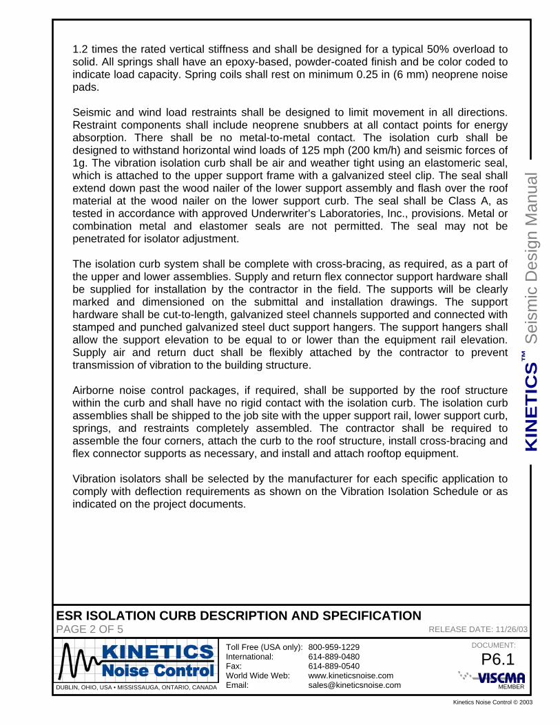
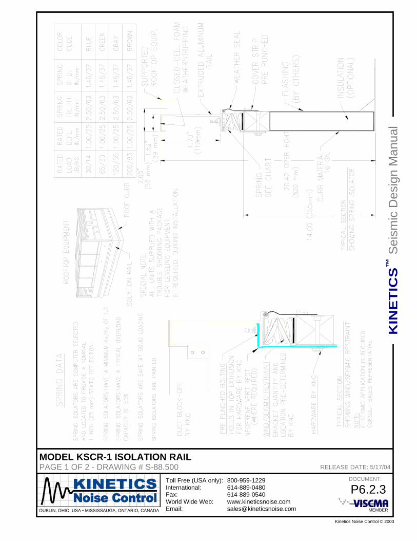
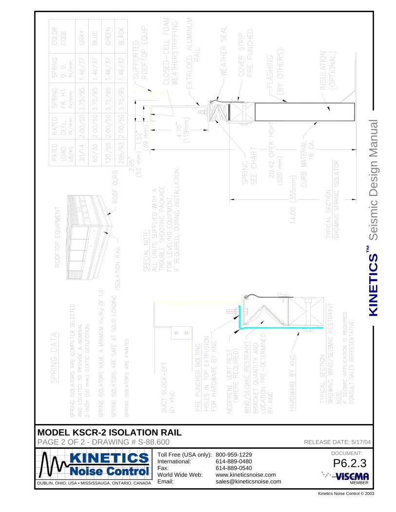
Kinetics Model KSCR • Internal seismic restraint • 100 mph wind restraint • 1 in or 2 in deflection springs • Supply and return flexible connector support
hardware • EPDM air- and weather-tight seal for non-ducted
applications • High profile, non-interference aluminum equipment
rail • Accessible, interchangeable springs
Specification All rooftop air-handling units shall be supported by vibration isolation curbs asmanufactured by Kinetics Noise Control. The vibration isolation curbs shall becomplete assemblies designed to resiliently support the equipment at the specifiedelevation and shall constitute a fully enclosed air- and weather-tight system. The isolation curb shall consist of an upper support rail with supply and return flexibleconnector supports on which the equipment and duct openings rest and a lowersupport curb which is attached to the roof structure, separated by free-standing,unhoused, laterally stable steel springs and lateral seismic and/or wind load restraints.The upper support rail shall provide continuous structural support for the rooftopequipment and shall be designed to provide isolation against casing-radiated vibrationin the rooftop equipment housing and structure borne vibration from rotating andmechanical equipment in the rooftop package. The upper support rail shall consist of an extruded aluminum structural shape with aminimum height of 4.75 in (121 mm) above the spring to preclude interference with therooftop equipment and permit access to inspect, level, or change the springs afterplacement of the rooftop equipment. The lower support curb shall be a formed channel fabricated of heavy gaugegalvanized steel with a continuous 1-1/2 in x 1-1/2 in (38 mm x 38 mm) nominal woodnailer. The base plate of the curb shall be 1 in (25 mm) wide and shall be welded,bolted or screwed to the building support steel. The lower support curb shall have a minimum elevation of 14 in (356 mm). Springcomponents shall be (1 in/25 mm) (2 in/51 mm) deflection, free-standing, unhoused,laterally stable steel springs. Springs shall have a lateral stiffness greater than 1.0times the rated vertical stiffness and shall be designed for a typical 50% overload tosolid. All springs shall have an epoxy-based, powder-coated finish and be color codedto indicate load capacity. Springs shall rest on a neoprene noise pad. The spring and
DUBLIN, OHIO, USA • MISSISSAUGA, ONTARIO, CANADA
Toll Free (USA only): International: Fax: World Wide Web: Email:
800-959-1229 614-889-0480 614-889-0540 www.kineticsnoise.com [email protected]
DOCUMENT:
P6.1
RELEASE DATE: 11/26/03
Kinetics Noise Control © 2003
KSCR ISOLATION CURB DESCRIPTION AND SPECIFICATION PAGE 4 OF 5
KIN
ET
ICS
™ S
eism
ic D
esig
n M
anua
l
MEMBER
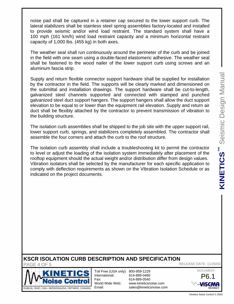
noise pad shall be captured in a retainer cap secured to the lower support curb. Thelateral stabilizers shall be stainless steel spring assemblies factory-located and installedto provide seismic and/or wind load restraint. The standard system shall have a100 mph (161 km/h) wind load restraint capacity and a minimum horizontal restraintcapacity of 1,000 lbs. (455 kg) in both axes. The weather seal shall run continuously around the perimeter of the curb and be joinedin the field with one seam using a double-faced elastomeric adhesive. The weather sealshall be fastened to the wood nailer of the lower support curb using screws and analuminum fascia strip. Supply and return flexible connector support hardware shall be supplied for installationby the contractor in the field. The supports will be clearly marked and dimensioned onthe submittal and installation drawings. The support hardware shall be cut-to-length,galvanized steel channels supported and connected with stamped and punchedgalvanized steel duct support hangers. The support hangers shall allow the duct supportelevation to be equal to or lower than the equipment rail elevation. Supply and return airduct shall be flexibly attached by the contractor to prevent transmission of vibration tothe building structure. The isolation curb assemblies shall be shipped to the job site with the upper support rail,lower support curb, springs, and stabilizers completely assembled. The contractor shallassemble the four corners and attach the curb to the roof structure. The isolation curb assembly shall include a troubleshooting kit to permit the contractorto level or adjust the loading of the isolation system immediately after placement of therooftop equipment should the actual weight and/or distribution differ from design values.Vibration isolators shall be selected by the manufacturer for each specific application tocomply with deflection requirements as shown on the Vibration Isolation Schedule or asindicated on the project documents.
DUBLIN, OHIO, USA • MISSISSAUGA, ONTARIO, CANADA
Toll Free (USA only): International: Fax: World Wide Web: Email:
800-959-1229 614-889-0480 614-889-0540 www.kineticsnoise.com [email protected]
DOCUMENT:
P6.1
KSR ISOLATION RAIL DESCRIPTION AND SPECIFICATION PAGE 5 OF 5 RELEASE DATE: 11/26/03
Kinetics Noise Control © 2003
KIN
ET
ICS
™ S
eism
ic D
esig
n M
anua
l
MEMBER
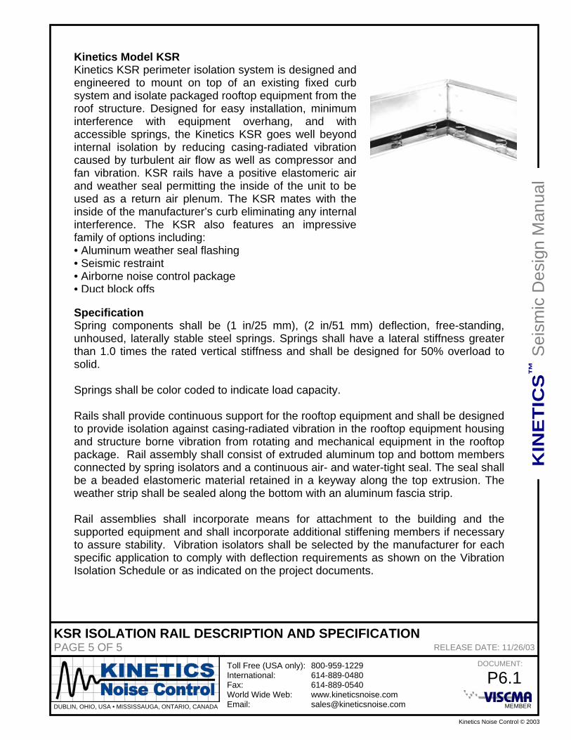
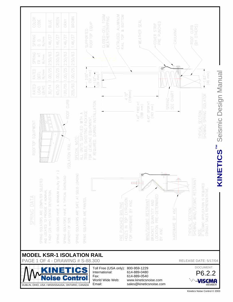
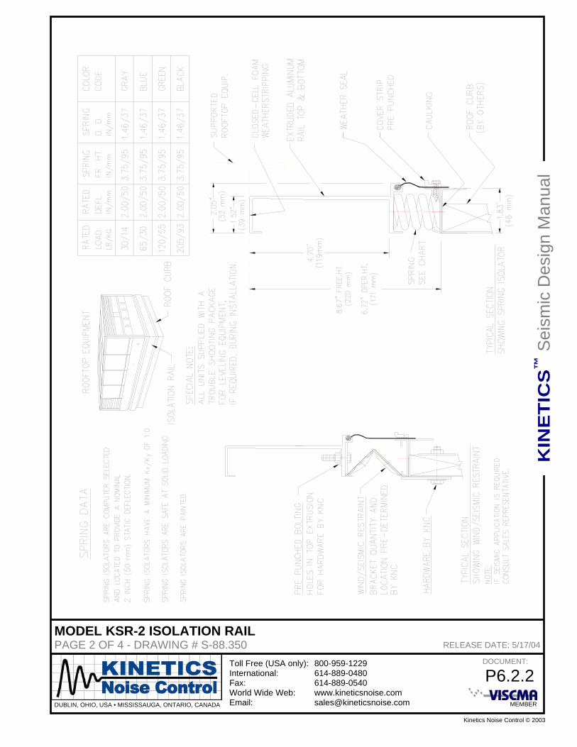
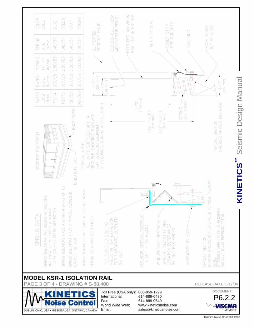
Kinetics Model KSR Kinetics KSR perimeter isolation system is designed andengineered to mount on top of an existing fixed curbsystem and isolate packaged rooftop equipment from theroof structure. Designed for easy installation, minimuminterference with equipment overhang, and withaccessible springs, the Kinetics KSR goes well beyondinternal isolation by reducing casing-radiated vibrationcaused by turbulent air flow as well as compressor andfan vibration. KSR rails have a positive elastomeric airand weather seal permitting the inside of the unit to beused as a return air plenum. The KSR mates with theinside of the manufacturer’s curb eliminating any internalinterference. The KSR also features an impressivefamily of options including: • Aluminum weather seal flashing • Seismic restraint • Airborne noise control package • Duct block offs
Specification Spring components shall be (1 in/25 mm), (2 in/51 mm) deflection, free-standing,unhoused, laterally stable steel springs. Springs shall have a lateral stiffness greaterthan 1.0 times the rated vertical stiffness and shall be designed for 50% overload tosolid. Springs shall be color coded to indicate load capacity. Rails shall provide continuous support for the rooftop equipment and shall be designedto provide isolation against casing-radiated vibration in the rooftop equipment housingand structure borne vibration from rotating and mechanical equipment in the rooftoppackage. Rail assembly shall consist of extruded aluminum top and bottom membersconnected by spring isolators and a continuous air- and water-tight seal. The seal shallbe a beaded elastomeric material retained in a keyway along the top extrusion. Theweather strip shall be sealed along the bottom with an aluminum fascia strip. Rail assemblies shall incorporate means for attachment to the building and thesupported equipment and shall incorporate additional stiffening members if necessaryto assure stability. Vibration isolators shall be selected by the manufacturer for eachspecific application to comply with deflection requirements as shown on the VibrationIsolation Schedule or as indicated on the project documents.
DUBLIN, OHIO, USA • MISSISSAUGA, ONTARIO, CANADA
Toll Free (USA only): International: Fax: World Wide Web: Email:
800-959-1229 614-889-0480 614-889-0540 www.kineticsnoise.com [email protected]
DOCUMENT:
P6.2.1
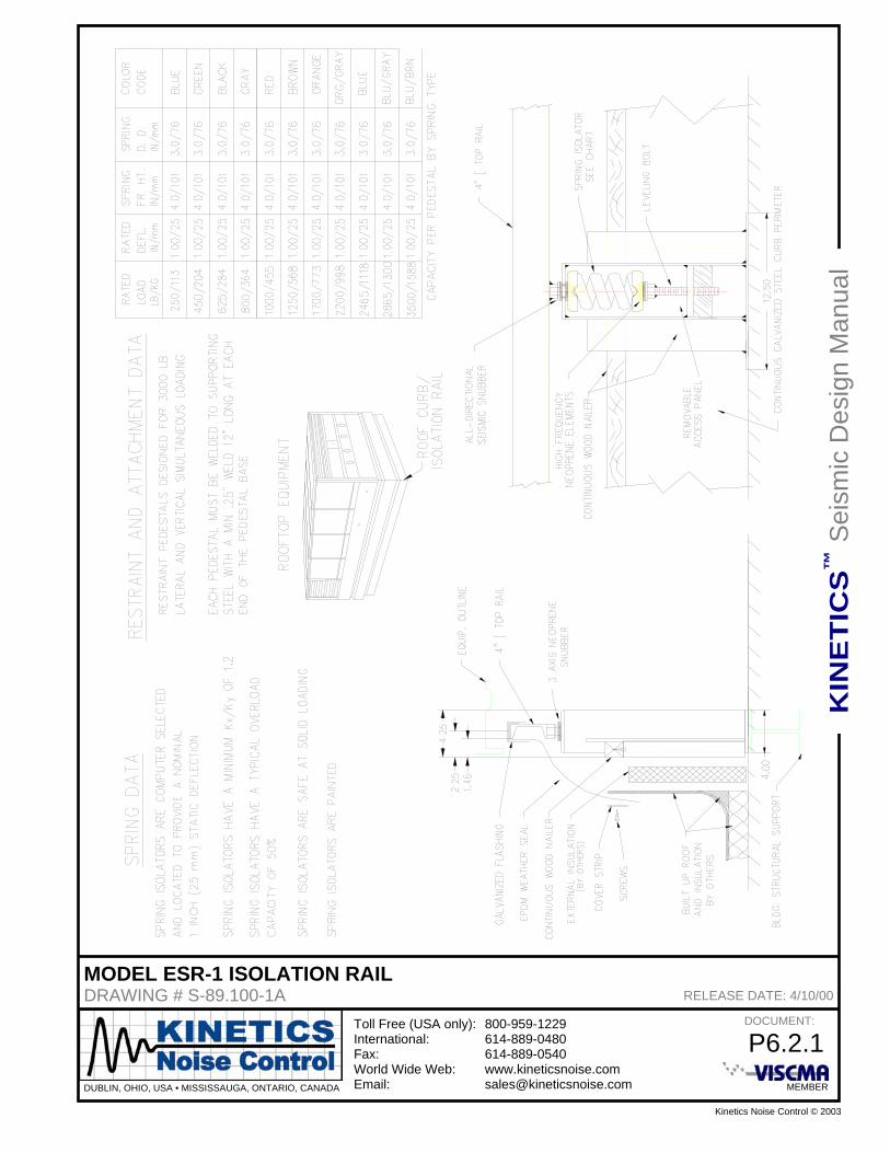
MODEL ESR-1 ISOLATION RAIL DRAWING # S-89.100-1A RELEASE DATE: 4/10/00
Kinetics Noise Control © 2003
KIN
ET
ICS
™ S
eism
ic D
esig
n M
anua
l
MEMBER
DUBLIN, OHIO, USA • MISSISSAUGA, ONTARIO, CANADA
Toll Free (USA only): International: Fax: World Wide Web: Email:
800-959-1229 614-889-0480 614-889-0540 www.kineticsnoise.com [email protected]
DOCUMENT:
P6.2.1
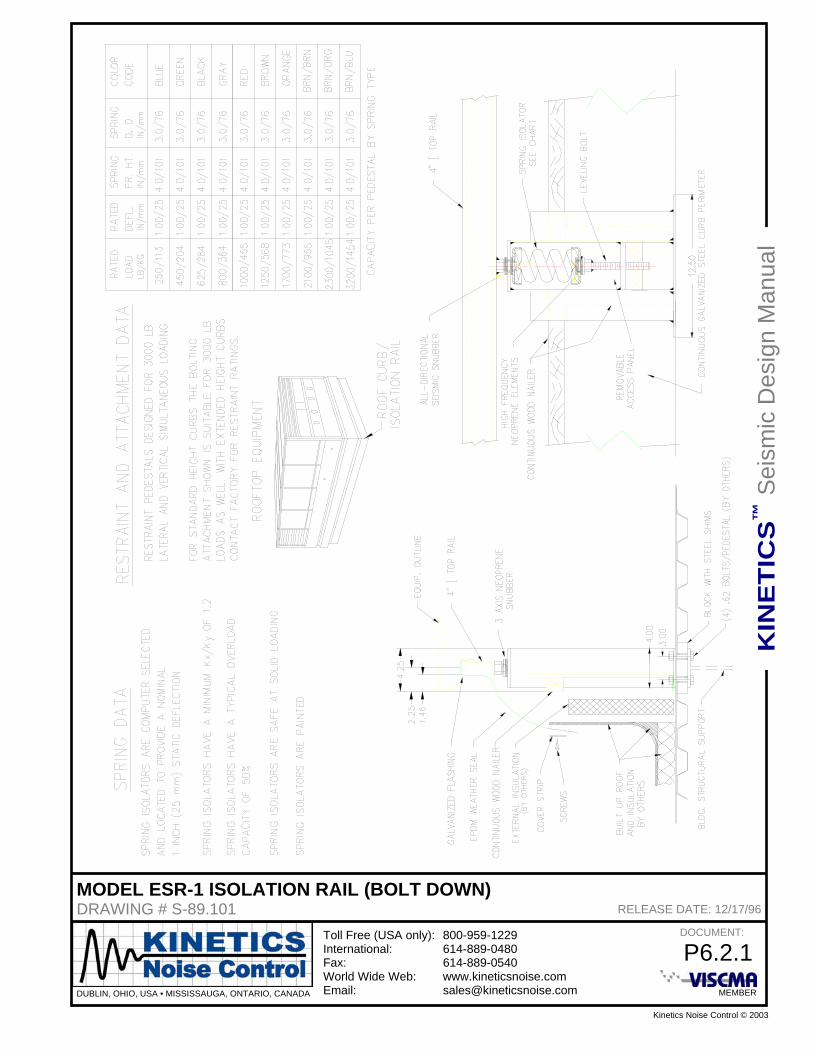
MODEL ESR-1 ISOLATION RAIL (BOLT DOWN) DRAWING # S-89.101 RELEASE DATE: 12/17/96
Kinetics Noise Control © 2003
KIN
ET
ICS
™ S
eism
ic D
esig
n M
anua
l
MEMBER
DUBLIN, OHIO, USA • MISSISSAUGA, ONTARIO, CANADA
Toll Free (USA only): International: Fax: World Wide Web: Email:
800-959-1229 614-889-0480 614-889-0540 www.kineticsnoise.com [email protected]
DOCUMENT:
P6.2.1
ESR-1 ISOLATION CURB W/ CONDENSER SUPPORT DRAWING # S-89.102-1A RELEASE DATE: 4/10/00
Kinetics Noise Control © 2003
KIN
ET
ICS
™ S
eism
ic D
esig
n M
anua
l
MEMBER
DUBLIN, OHIO, USA • MISSISSAUGA, ONTARIO, CANADA
Toll Free (USA only): International: Fax: World Wide Web: Email:
800-959-1229 614-889-0480 614-889-0540 www.kineticsnoise.com [email protected]
DOCUMENT:
P6.2.1
ESR-2 ISOLATION RAIL DRAWING # S-89.200-1A RELEASE DATE: 1/16/01
Kinetics Noise Control © 2003
KIN
ET
ICS
™ S
eism
ic D
esig
n M
anua
l
MEMBER
DUBLIN, OHIO, USA • MISSISSAUGA, ONTARIO, CANADA
Toll Free (USA only): International: Fax: World Wide Web: Email:
800-959-1229 614-889-0480 614-889-0540 www.kineticsnoise.com [email protected]
DOCUMENT:
P6.2.1
MODEL ESR-2 ISOLATION RAIL (BOLT DOWN) DRAWING # S-89.201 RELEASE DATE: 12/17/96
Kinetics Noise Control © 2003
KIN
ET
ICS
™ S
eism
ic D
esig
n M
anua
l
MEMBER
DUBLIN, OHIO, USA • MISSISSAUGA, ONTARIO, CANADA
Toll Free (USA only): International: Fax: World Wide Web: Email:
800-959-1229 614-889-0480 614-889-0540 www.kineticsnoise.com [email protected]
DOCUMENT:
P6.2.1
ESR-2 ISOLATION CURB W/ CONDENSER SUPPORT DRAWING # S-89.202-1A RELEASE DATE: 1/16/01
Kinetics Noise Control © 2003
KIN
ET
ICS
™ S
eism
ic D
esig
n M
anua
l
MEMBER

DUBLIN, OHIO, USA • MISSISSAUGA, ONTARIO, CANADA
Toll Free (USA only): International: Fax: World Wide Web: Email:
800-959-1229 614-889-0480 614-889-0540 www.kineticsnoise.com [email protected]
DOCUMENT:
P6.2.1
MODEL ESR-3 ISOLATION RAIL DRAWING # S-89.300 RELEASE DATE: 8/20/97
Kinetics Noise Control © 2003
KIN
ET
ICS
™ S
eism
ic D
esig
n M
anua
l
MEMBER

DUBLIN, OHIO, USA • MISSISSAUGA, ONTARIO, CANADA
Toll Free (USA only): International: Fax: World Wide Web: Email:
800-959-1229 614-889-0480 614-889-0540 www.kineticsnoise.com [email protected]
DOCUMENT:
P6.2.1
MODEL ESR-3 ISOLATION RAIL (BOLT DOWN) DRAWING # S-89.301 RELEASE DATE: 12/17/96
Kinetics Noise Control © 2003
KIN
ET
ICS
™ S
eism
ic D
esig
n M
anua
l
MEMBER
DUBLIN, OHIO, USA • MISSISSAUGA, ONTARIO, CANADA
Toll Free (USA only): International: Fax: World Wide Web: Email:
800-959-1229 614-889-0480 614-889-0540 www.kineticsnoise.com [email protected]
DOCUMENT:
P6.2.1
MODEL ESR-4 ISOLATION RAIL DRAWING # S-89.400-1A RELEASE DATE: 6/12/00
Kinetics Noise Control © 2003
KIN
ET
ICS
™ S
eism
ic D
esig
n M
anua
l
MEMBER

DUBLIN, OHIO, USA • MISSISSAUGA, ONTARIO, CANADA
Toll Free (USA only): International: Fax: World Wide Web: Email:
800-959-1229 614-889-0480 614-889-0540 www.kineticsnoise.com [email protected]
DOCUMENT:
P6.2.1
MODEL ESR-4 ISOLATION RAIL (BOLT DOWN) DRAWING # S-89.401-1A RELEASE DATE: 6/12/00
Kinetics Noise Control © 2003
KIN
ET
ICS
™ S
eism
ic D
esig
n M
anua
l
MEMBER
DUBLIN, OHIO, USA • MISSISSAUGA, ONTARIO, CANADA
Toll Free (USA only): International: Fax: World Wide Web: Email:
800-959-1229 614-889-0480 614-889-0540 www.kineticsnoise.com [email protected]
DOCUMENT:
P6.2.1
MODEL ESR-4 ISOLATION CURB W/ COND. SUPPORT DRAWING # S-89.402-1A RELEASE DATE: 6/12/00
Kinetics Noise Control © 2003
KIN
ET
ICS
™ S
eism
ic D
esig
n M
anua
l
MEMBER
DUBLIN, OHIO, USA • MISSISSAUGA, ONTARIO, CANADA
Toll Free (USA only): International: Fax: World Wide Web: Email:
800-959-1229 614-889-0480 614-889-0540 www.kineticsnoise.com [email protected]
DOCUMENT:
P6.2.2
MODEL KSR-1 ISOLATION RAIL PAGE 1 OF 4 - DRAWING # S-88.300 RELEASE DATE: 5/17/04
Kinetics Noise Control © 2003
KIN
ET
ICS
™ S
eism
ic D
esig
n M
anua
l
MEMBER
DUBLIN, OHIO, USA • MISSISSAUGA, ONTARIO, CANADA
Toll Free (USA only): International: Fax: World Wide Web: Email:
800-959-1229 614-889-0480 614-889-0540 www.kineticsnoise.com [email protected]
DOCUMENT:
P6.2.2
MODEL KSR-2 ISOLATION RAIL PAGE 2 OF 4 - DRAWING # S-88.350 RELEASE DATE: 5/17/04
Kinetics Noise Control © 2003
KIN
ET
ICS
™ S
eism
ic D
esig
n M
anua
l
MEMBER
DUBLIN, OHIO, USA • MISSISSAUGA, ONTARIO, CANADA
Toll Free (USA only): International: Fax: World Wide Web: Email:
800-959-1229 614-889-0480 614-889-0540 www.kineticsnoise.com [email protected]
DOCUMENT:
P6.2.2
MODEL KSR-1 ISOLATION RAIL PAGE 3 OF 4 - DRAWING # S-88.400 RELEASE DATE: 5/17/04
Kinetics Noise Control © 2003
KIN
ET
ICS
™ S
eism
ic D
esig
n M
anua
l
MEMBER

DUBLIN, OHIO, USA • MISSISSAUGA, ONTARIO, CANADA
Toll Free (USA only): International: Fax: World Wide Web: Email:
800-959-1229 614-889-0480 614-889-0540 www.kineticsnoise.com [email protected]
DOCUMENT:
P6.2.2
MODEL KSR-2 ISOLATION RAIL PAGE 4 OF 4 - DRAWING # S-88.450 RELEASE DATE: 5/17/04
Kinetics Noise Control © 2003
KIN
ET
ICS
™ S
eism
ic D
esig
n M
anua
l
MEMBER
DUBLIN, OHIO, USA • MISSISSAUGA, ONTARIO, CANADA
Toll Free (USA only): International: Fax: World Wide Web: Email:
800-959-1229 614-889-0480 614-889-0540 www.kineticsnoise.com [email protected]
DOCUMENT:
P6.2.3
MODEL KSCR-1 ISOLATION RAIL PAGE 1 OF 2 - DRAWING # S-88.500 RELEASE DATE: 5/17/04
Kinetics Noise Control © 2003
KIN
ET
ICS
™ S
eism
ic D
esig
n M
anua
l
MEMBER
DUBLIN, OHIO, USA • MISSISSAUGA, ONTARIO, CANADA
Toll Free (USA only): International: Fax: World Wide Web: Email:
800-959-1229 614-889-0480 614-889-0540 www.kineticsnoise.com [email protected]
DOCUMENT:
P6.2.3
MODEL KSCR-2 ISOLATION RAIL PAGE 2 OF 2 - DRAWING # S-88.600 RELEASE DATE: 5/17/04
Kinetics Noise Control © 2003
KIN
ET
ICS
™ S
eism
ic D
esig
n M
anua
l
MEMBER
DUBLIN, OHIO, USA • MISSISSAUGA, ONTARIO, CANADA
Toll Free (USA only): International: Fax: World Wide Web: Email:
800-959-1229 614-889-0480 614-889-0540 www.kineticsnoise.com [email protected]
DOCUMENT:
P6.5
ESR / KSR / KSCR Installation Instructions PAGE 1 OF 1 RELEASE DATE: 05/07/04
The installation instruction for the ESR, KSR, and KSCR
can be found on our website,
http://www.kineticsnoise.com
Kinetics Noise Control © 2003
KIN
ET
ICS
™ S
eism
ic D
esig
n M
anua
l
MEMBER