kinetics™ pipe & duct seismic application manual ii... · 2015-07-31 · kinetics™ pipe...
TRANSCRIPT
KINETICS™ Pipe & Duct Seismic Application Manual
STRUCTURAL ATTACHMENTS FOR PIPE AND DUCT RESTRAINTSPAGE 1 of 65 SECTION – I5.0
Toll Free (USA Only): 800-959-1229 RELEASED ON: 09/04/2009International: 614-889-0480FAX 614-889-0540World Wide Web: www.kineticsnoise.comE-mail: [email protected]
Dublin, Ohio, USA Mississauga, Ontario, Canada Member
STRUCTURAL ATTACHMENTS FOR PIPE AND DUCT RESTRAINTS
I5.1 – Introduction:
This section will present several basic arrangements for attaching seismic cable restraints to the
building structure. The figures and descriptions in this section will be based on the Kinetics Noise
Control drawings SS-20070951, SS-20070952, and SS-20070953 titled Concrete/Masonry
Attachment – Sheet B, Steel Attachment – Sheet C, and Wood Attachment – D respectively.
There are several drawings in this specific series. They have been designed to aid the installing
contractor with the installation of seismic cable restraints for pipe and duct. Each drawing has a
number designation ranging from SS-20070950 through SS-20070959. Also each drawing is
specified by a particular letter designation ranging from Sheet A though Sheet H. The drawing
numbers are in no particular order. However, the letter designations are in strict alphabetical
order. Each of the drawings in this series has several views on each sheet designated by a
specific letter. Where the figures in this section correspond with those views on the Kinetics Noise
Control drawings SS-20070950 through SS-20070959 they will be cross referenced by sheet letter
and figure letter, for instance Sheet C – View M.
Kinetics Noise Control provides attachment kits for their seismic restraint cable kits for pipe and
duct. Kinetics Noise Control will, when requested to do so, provide a certification for the products
that they sell. This certification will state that the seismic restraint cable and attachment kits will
meet the seismic design requirements for the project in question when properly installed at the
correct spacing. It is important to keep in mind that this certification does not extend to the
building structure. Kinetics Noise Control is a manufacturer of vibration isolation and seismic
restraint devices for the HVAC industry, and as such has no control over the design of the building
structure. It is the responsibility of the structural engineer of record, and in some cases the
architect of record, to approve the structural connections for the seismic restraints for pipe and
duct.
KINETICS™ Pipe & Duct Seismic Application Manual
STRUCTURAL ATTACHMENTS FOR PIPE AND DUCT RESTRAINTSPAGE 2 of 65 SECTION – I5.0
Toll Free (USA Only): 800-959-1229 RELEASED ON: 09/04/2009International: 614-889-0480FAX 614-889-0540World Wide Web: www.kineticsnoise.comE-mail: [email protected]
Dublin, Ohio, USA Mississauga, Ontario, Canada Member
I5.2 – KSUA Attachment Brackets:
I5.2.1 – KSUA Brackets – Basic Sizes & Installation:
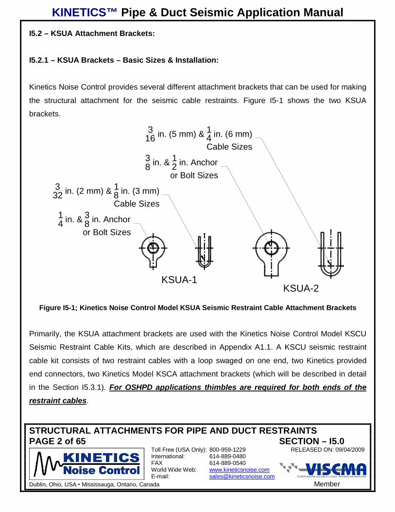
Kinetics Noise Control provides several different attachment brackets that can be used for making
the structural attachment for the seismic cable restraints. Figure I5-1 shows the two KSUA
brackets.
KSUA-1KSUA-2
14 in. & 3
8 in. Anchoror Bolt Sizes
332 in. (2 mm) & 1
8 in. (3 mm)Cable Sizes
38 in. & 1
2 in. Anchoror Bolt Sizes
316 in. (5 mm) & 1
4 in. (6 mm)Cable Sizes
Figure I5-1; Kinetics Noise Control Model KSUA Seismic Restraint Cable Attachment Brackets
Primarily, the KSUA attachment brackets are used with the Kinetics Noise Control Model KSCU
Seismic Restraint Cable Kits, which are described in Appendix A1.1. A KSCU seismic restraint
cable kit consists of two restraint cables with a loop swaged on one end, two Kinetics provided
end connectors, two Kinetics Model KSCA attachment brackets (which will be described in detail
in the Section I5.3.1). For OSHPD applications thimbles are required for both ends of the
restraint cables.
KINETICS™ Pipe & Duct Seismic Application Manual
STRUCTURAL ATTACHMENTS FOR PIPE AND DUCT RESTRAINTSPAGE 3 of 65 SECTION – I5.0
Toll Free (USA Only): 800-959-1229 RELEASED ON: 09/04/2009International: 614-889-0480FAX 614-889-0540World Wide Web: www.kineticsnoise.comE-mail: [email protected]
Dublin, Ohio, USA Mississauga, Ontario, Canada Member
View #2Side
KSUA - Open
View #3Side
KSUA - Closed
View #1Front
KSUA - Installed
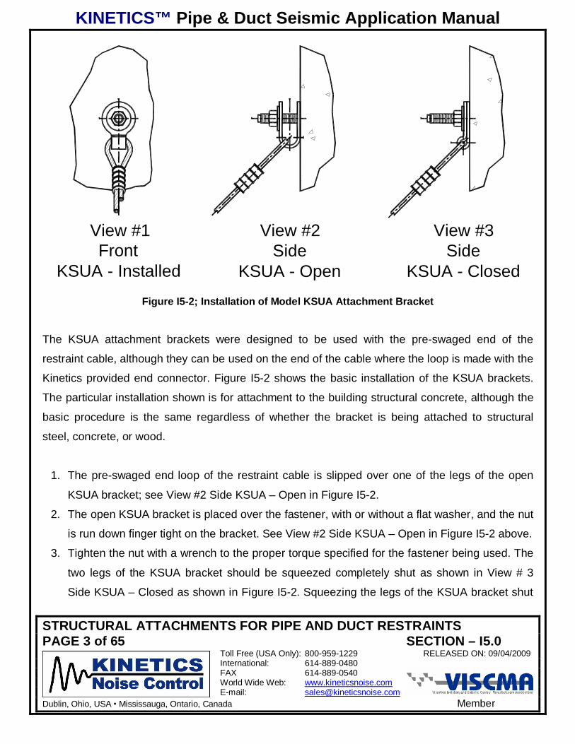
Figure I5-2; Installation of Model KSUA Attachment Bracket
The KSUA attachment brackets were designed to be used with the pre-swaged end of the
restraint cable, although they can be used on the end of the cable where the loop is made with the
Kinetics provided end connector. Figure I5-2 shows the basic installation of the KSUA brackets.
The particular installation shown is for attachment to the building structural concrete, although the
basic procedure is the same regardless of whether the bracket is being attached to structural
steel, concrete, or wood.
1. The pre-swaged end loop of the restraint cable is slipped over one of the legs of the open
KSUA bracket; see View #2 Side KSUA – Open in Figure I5-2.
2. The open KSUA bracket is placed over the fastener, with or without a flat washer, and the nut
is run down finger tight on the bracket. See View #2 Side KSUA – Open in Figure I5-2 above.
3. Tighten the nut with a wrench to the proper torque specified for the fastener being used. The
two legs of the KSUA bracket should be squeezed completely shut as shown in View # 3
Side KSUA – Closed as shown in Figure I5-2. Squeezing the legs of the KSUA bracket shut
KINETICS™ Pipe & Duct Seismic Application Manual
STRUCTURAL ATTACHMENTS FOR PIPE AND DUCT RESTRAINTSPAGE 4 of 65 SECTION – I5.0
Toll Free (USA Only): 800-959-1229 RELEASED ON: 09/04/2009International: 614-889-0480FAX 614-889-0540World Wide Web: www.kineticsnoise.comE-mail: [email protected]
Dublin, Ohio, USA Mississauga, Ontario, Canada Member
will form a loop for the restraint cable. The cable should be loose and free to move inside the
loop of the KSUA bracket.
I5.2.2 – KSUA Brackets – Attachment to Steel:
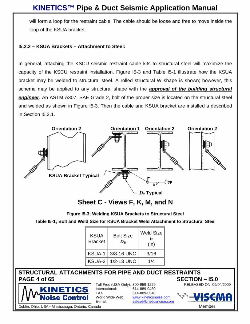
In general, attaching the KSCU seismic restraint cable kits to structural steel will maximize the
capacity of the KSCU restraint installation. Figure I5-3 and Table I5-1 illustrate how the KSUA
bracket may be welded to structural steel. A rolled structural W shape is shown; however, this
scheme may be applied to any structural shape with the approval of the building structural
engineer. An ASTM A307, SAE Grade 2, bolt of the proper size is located on the structural steel
and welded as shown in Figure I5-3. Then the cable and KSUA bracket are installed a described
in Section I5.2.1.
h
DB Typical
Sheet C - Views F, K, M, and N
Typ
KSUA Bracket Typical
Orientation 1 Orientation 2 Orientation 2Orientation 2
Figure I5-3; Welding KSUA Brackets to Structural SteelTable I5-1; Bolt and Weld Size for KSUA Bracket Weld Attachment to Structural Steel
KSUABracket
Bolt SizeDB
Weld Sizeh
(in)
KSUA-1 3/8-16 UNC 3/16KSUA-2 1/2-13 UNC 1/4
KINETICS™ Pipe & Duct Seismic Application Manual
STRUCTURAL ATTACHMENTS FOR PIPE AND DUCT RESTRAINTSPAGE 5 of 65 SECTION – I5.0
Toll Free (USA Only): 800-959-1229 RELEASED ON: 09/04/2009International: 614-889-0480FAX 614-889-0540World Wide Web: www.kineticsnoise.comE-mail: [email protected]
Dublin, Ohio, USA Mississauga, Ontario, Canada Member
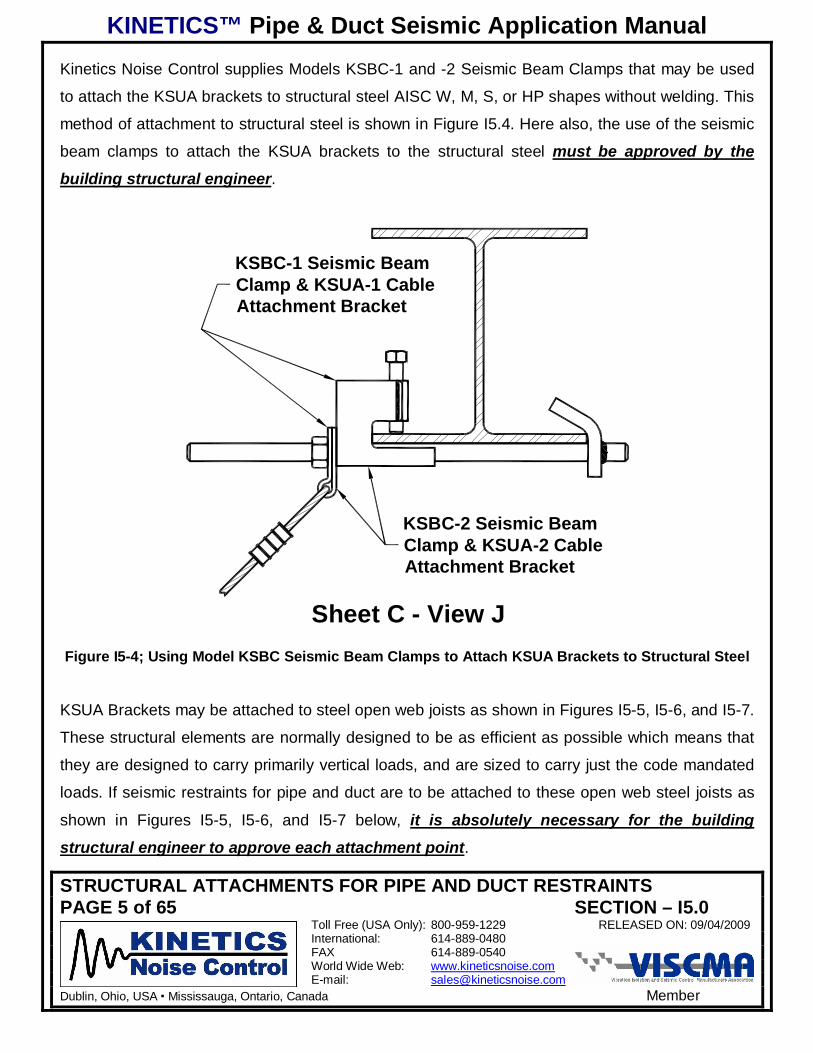
Kinetics Noise Control supplies Models KSBC-1 and -2 Seismic Beam Clamps that may be used
to attach the KSUA brackets to structural steel AISC W, M, S, or HP shapes without welding. This
method of attachment to structural steel is shown in Figure I5.4. Here also, the use of the seismic
beam clamps to attach the KSUA brackets to the structural steel must be approved by the
building structural engineer.
Sheet C - View J
KSBC-2 Seismic BeamClamp & KSUA-2 CableAttachment Bracket
KSBC-1 Seismic BeamClamp & KSUA-1 CableAttachment Bracket
Figure I5-4; Using Model KSBC Seismic Beam Clamps to Attach KSUA Brackets to Structural Steel
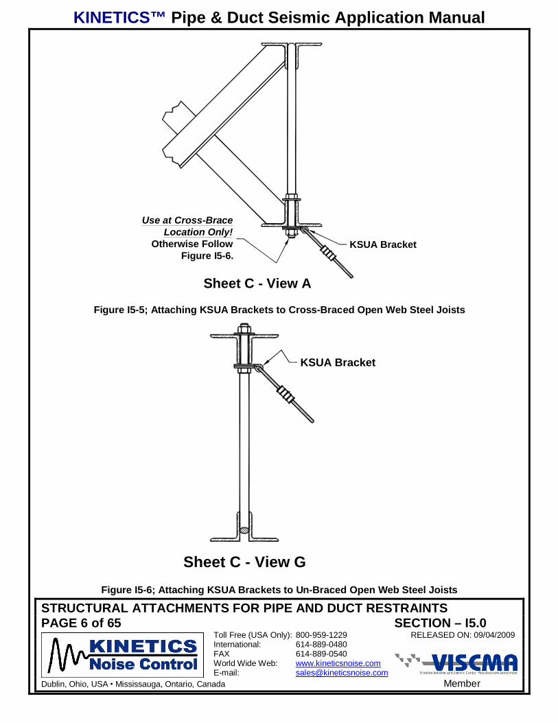
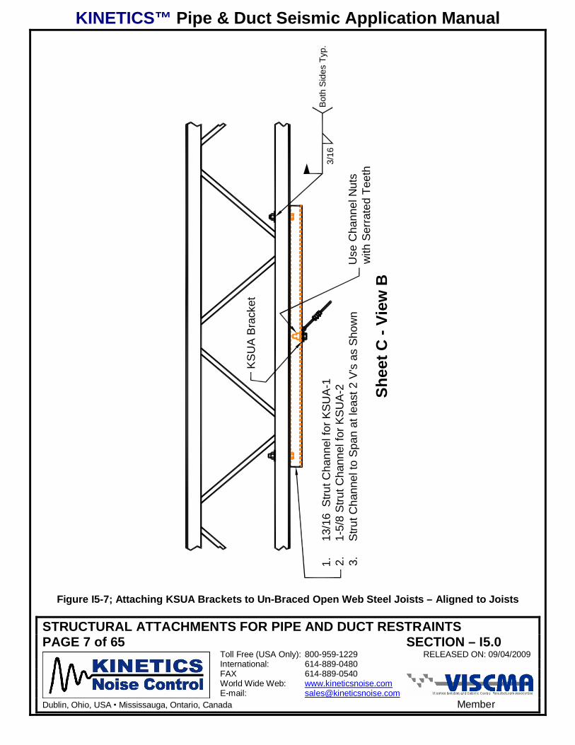
KSUA Brackets may be attached to steel open web joists as shown in Figures I5-5, I5-6, and I5-7.
These structural elements are normally designed to be as efficient as possible which means that
they are designed to carry primarily vertical loads, and are sized to carry just the code mandated
loads. If seismic restraints for pipe and duct are to be attached to these open web steel joists as
shown in Figures I5-5, I5-6, and I5-7 below, it is absolutely necessary for the building
structural engineer to approve each attachment point.
KINETICS™ Pipe & Duct Seismic Application Manual
STRUCTURAL ATTACHMENTS FOR PIPE AND DUCT RESTRAINTSPAGE 6 of 65 SECTION – I5.0
Toll Free (USA Only): 800-959-1229 RELEASED ON: 09/04/2009International: 614-889-0480FAX 614-889-0540World Wide Web: www.kineticsnoise.comE-mail: [email protected]
Dublin, Ohio, USA Mississauga, Ontario, Canada Member
Sheet C - View A
Use at Cross-BraceLocation Only!
Otherwise FollowFigure I5-6.
KSUA Bracket
Figure I5-5; Attaching KSUA Brackets to Cross-Braced Open Web Steel Joists
Sheet C - View G
KSUA Bracket
Figure I5-6; Attaching KSUA Brackets to Un-Braced Open Web Steel Joists
KINETICS™ Pipe & Duct Seismic Application Manual
STRUCTURAL ATTACHMENTS FOR PIPE AND DUCT RESTRAINTSPAGE 7 of 65 SECTION – I5.0
Toll Free (USA Only): 800-959-1229 RELEASED ON: 09/04/2009International: 614-889-0480FAX 614-889-0540World Wide Web: www.kineticsnoise.comE-mail: [email protected]
Dublin, Ohio, USA Mississauga, Ontario, Canada Member
Shee
t C -
View
B
1.13
/16
Stru
t Cha
nnel
for K
SU
A-1
2.1-
5/8
Stru
t Cha
nnel
for K
SU
A-2
3.S
trut C
hann
el to
Spa
n at
leas
t 2 V
's a
s S
how
nU
se C
hann
el N
uts
with
Ser
rate
d Te
eth
KS
UA
Bra
cket
Bot
h S
ides
Typ
.3/
16
Figure I5-7; Attaching KSUA Brackets to Un-Braced Open Web Steel Joists – Aligned to Joists
KINETICS™ Pipe & Duct Seismic Application Manual
STRUCTURAL ATTACHMENTS FOR PIPE AND DUCT RESTRAINTSPAGE 8 of 65 SECTION – I5.0
Toll Free (USA Only): 800-959-1229 RELEASED ON: 09/04/2009International: 614-889-0480FAX 614-889-0540World Wide Web: www.kineticsnoise.comE-mail: [email protected]
Dublin, Ohio, USA Mississauga, Ontario, Canada Member
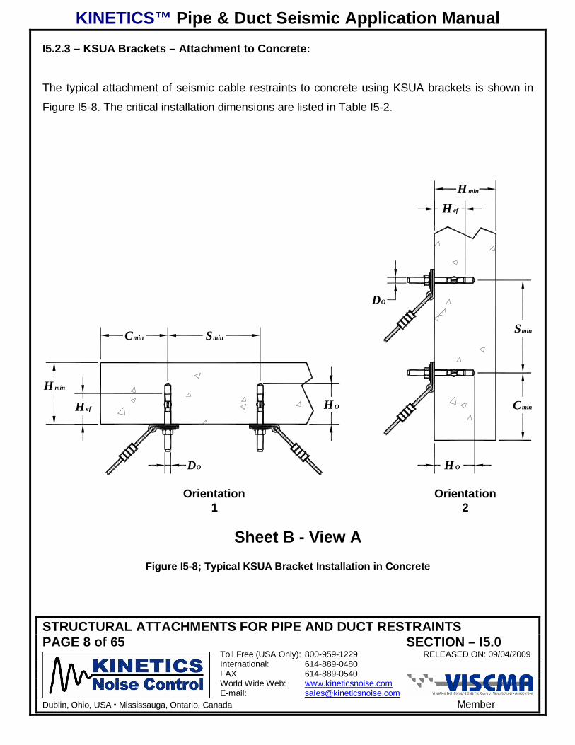
I5.2.3 – KSUA Brackets – Attachment to Concrete:
The typical attachment of seismic cable restraints to concrete using KSUA brackets is shown in
Figure I5-8. The critical installation dimensions are listed in Table I5-2.
H OH ef
DO
H min
Cmin Smin
DO
Smin
Cmin
H ef
H min
H O
Orientation1
Orientation2
Sheet B - View AFigure I5-8; Typical KSUA Bracket Installation in Concrete
KINETICS™ Pipe & Duct Seismic Application Manual
STRUCTURAL ATTACHMENTS FOR PIPE AND DUCT RESTRAINTSPAGE 9 of 65 SECTION – I5.0
Toll Free (USA Only): 800-959-1229 RELEASED ON: 09/04/2009International: 614-889-0480FAX 614-889-0540World Wide Web: www.kineticsnoise.comE-mail: [email protected]
Dublin, Ohio, USA Mississauga, Ontario, Canada Member
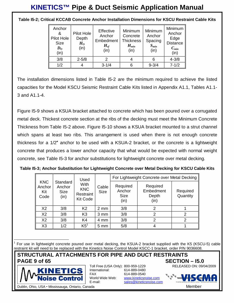
Table I5-2; Critical KCCAB Concrete Anchor Installation Dimensions for KSCU Restraint Cable Kits
Anchor&
Pilot HoleSizeDO(in)
Pilot HoleDepth
HO(in)
EffectiveAnchor
EmbedmentHef(in)
MinimumConcreteThickness
Hmin(in)
MinimumAnchorSpacing
Smin(in)
MinimumAnchorEdge
DistanceCmin(in)
3/8 2-5/8 2 4 6 4-3/81/2 4 3-1/4 6 9-3/4 7-1/2
The installation dimensions listed in Table I5-2 are the minimum required to achieve the listed
capacities for the Model KSCU Seismic Restraint Cable Kits listed in Appendix A1.1, Tables A1.1-
3 and A1.1-4.
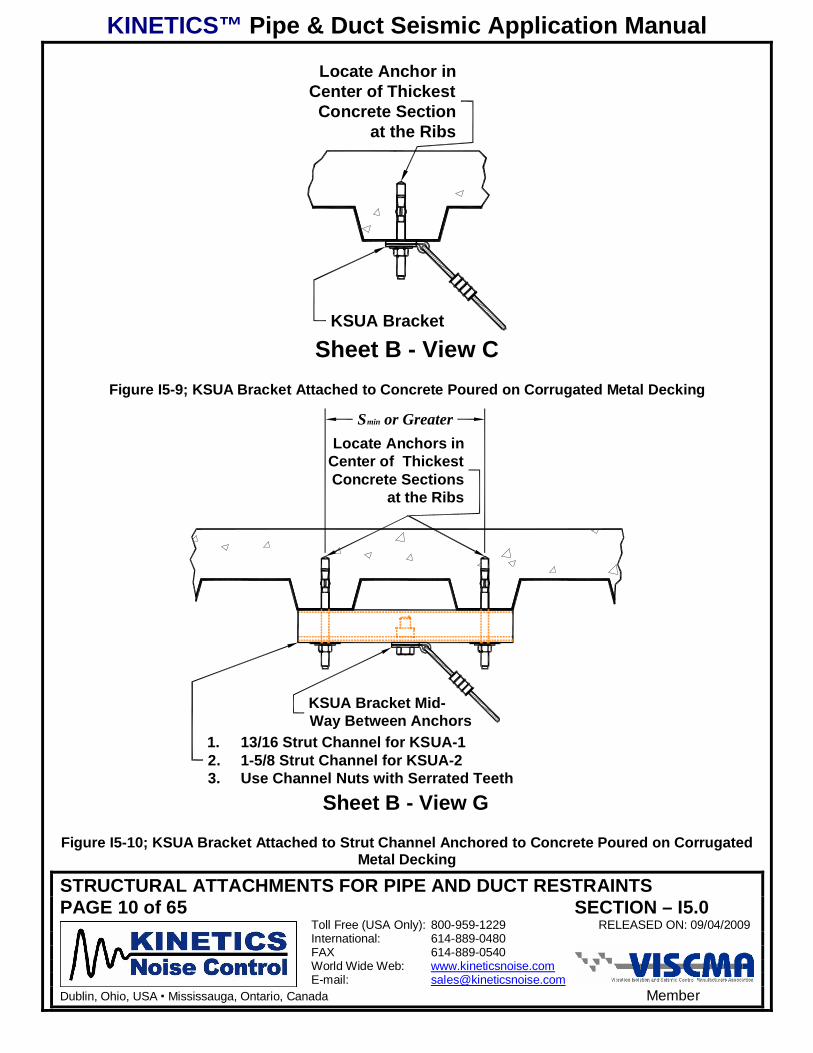
Figure I5-9 shows a KSUA bracket attached to concrete which has been poured over a corrugated
metal deck. Thickest concrete section at the ribs of the decking must meet the Minimum Concrete
Thickness from Table I5-2 above. Figure I5-10 shows a KSUA bracket mounted to a strut channel
which spans at least two ribs. This arrangement is used when there is not enough concrete
thickness for a 1/2 anchor to be used with a KSUA-2 bracket, or the concrete is a lightweight
concrete that produces a lower anchor capacity that what would be expected with normal weight
concrete, see Table I5-3 for anchor substitutions for lightweight concrete over metal decking.
Table I5-3; Anchor Substitution for Lightweight Concrete over Metal Decking for KSCU Cable Kits
For Lightweight Concrete over Metal DeckingKNC
AnchorKit
Code
StandardAnchor
Size(in)
UsedWithKNC
RestraintKit Code
CableSize
RequiredAnchor
Size(in)
RequiredEmbedment
Depth(in)
RequiredQuantity
X2 3/8 K2 2 mm 3/8 2 1X2 3/8 K3 3 mm 3/8 2 2X2 3/8 K4 4 mm 3/8 2 2X3 1/2 K51 5 mm 5/8 4 1
1 For use in lightweight concrete poured over metal decking, the KSUA-2 bracket supplied with the K5 (KSCU-5) cablerestraint kit will need to be replaced with the Kinetics Noise Control Model KSCC-1 bracket, order P/N 9036608.
KINETICS™ Pipe & Duct Seismic Application Manual
STRUCTURAL ATTACHMENTS FOR PIPE AND DUCT RESTRAINTSPAGE 10 of 65 SECTION – I5.0
Toll Free (USA Only): 800-959-1229 RELEASED ON: 09/04/2009International: 614-889-0480FAX 614-889-0540World Wide Web: www.kineticsnoise.comE-mail: [email protected]
Dublin, Ohio, USA Mississauga, Ontario, Canada Member
Locate Anchor inCenter of ThickestConcrete Section
at the Ribs
KSUA Bracket
Sheet B - View CFigure I5-9; KSUA Bracket Attached to Concrete Poured on Corrugated Metal Decking
Smin or Greater
1. 13/16 Strut Channel for KSUA-12. 1-5/8 Strut Channel for KSUA-23. Use Channel Nuts with Serrated Teeth
KSUA Bracket Mid-Way Between Anchors
Locate Anchors inCenter of ThickestConcrete Sections
at the Ribs
Sheet B - View G
Figure I5-10; KSUA Bracket Attached to Strut Channel Anchored to Concrete Poured on CorrugatedMetal Decking
KINETICS™ Pipe & Duct Seismic Application Manual
STRUCTURAL ATTACHMENTS FOR PIPE AND DUCT RESTRAINTSPAGE 11 of 65 SECTION – I5.0
Toll Free (USA Only): 800-959-1229 RELEASED ON: 09/04/2009International: 614-889-0480FAX 614-889-0540World Wide Web: www.kineticsnoise.comE-mail: [email protected]
Dublin, Ohio, USA Mississauga, Ontario, Canada Member
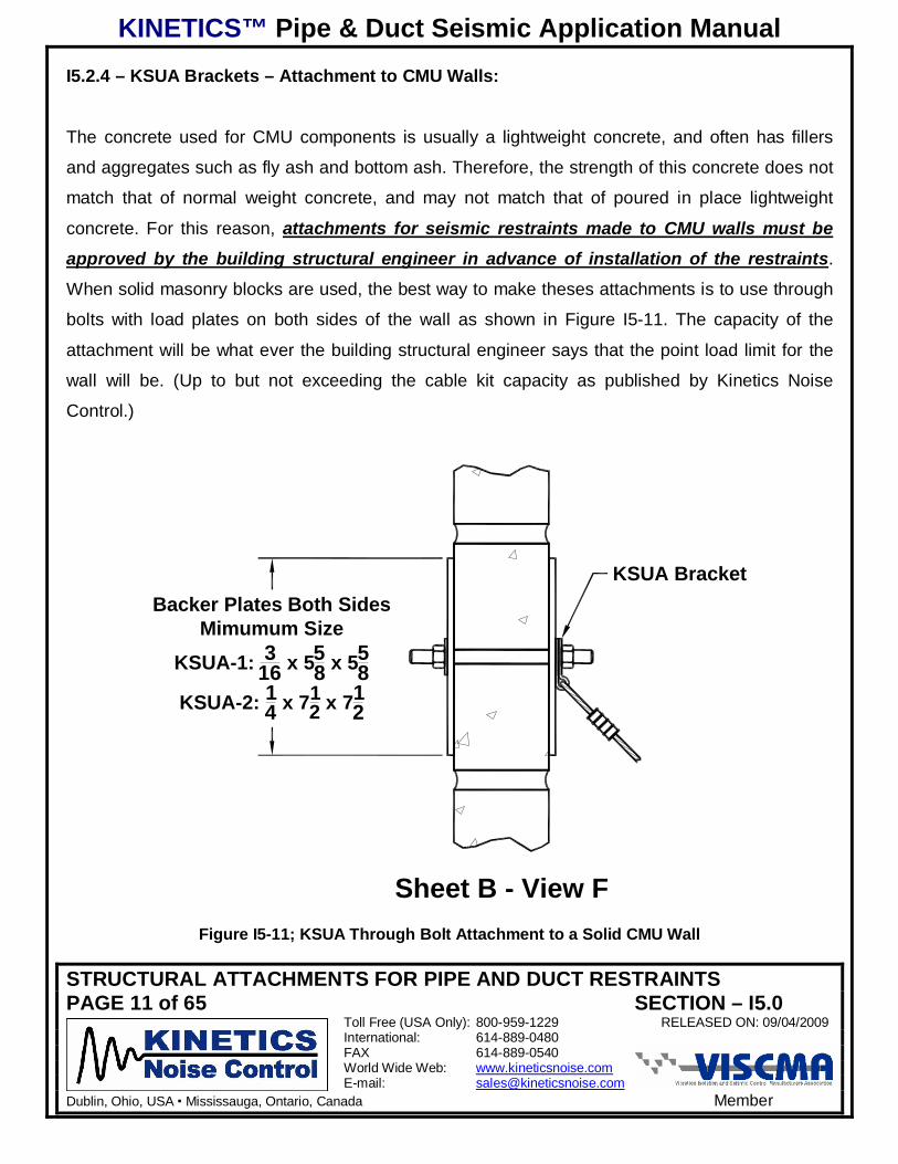
I5.2.4 – KSUA Brackets – Attachment to CMU Walls:
The concrete used for CMU components is usually a lightweight concrete, and often has fillers
and aggregates such as fly ash and bottom ash. Therefore, the strength of this concrete does not
match that of normal weight concrete, and may not match that of poured in place lightweight
concrete. For this reason, attachments for seismic restraints made to CMU walls must be
approved by the building structural engineer in advance of installation of the restraints.
When solid masonry blocks are used, the best way to make theses attachments is to use through
bolts with load plates on both sides of the wall as shown in Figure I5-11. The capacity of the
attachment will be what ever the building structural engineer says that the point load limit for the
wall will be. (Up to but not exceeding the cable kit capacity as published by Kinetics Noise
Control.)
Sheet B - View F
KSUA BracketBacker Plates Both Sides
Mimumum SizeKSUA-1: 3
16 x 558 x 55
8KSUA-2: 1
4 x 712 x 71
2
Figure I5-11; KSUA Through Bolt Attachment to a Solid CMU Wall
KINETICS™ Pipe & Duct Seismic Application Manual
STRUCTURAL ATTACHMENTS FOR PIPE AND DUCT RESTRAINTSPAGE 12 of 65 SECTION – I5.0
Toll Free (USA Only): 800-959-1229 RELEASED ON: 09/04/2009International: 614-889-0480FAX 614-889-0540World Wide Web: www.kineticsnoise.comE-mail: [email protected]
Dublin, Ohio, USA Mississauga, Ontario, Canada Member
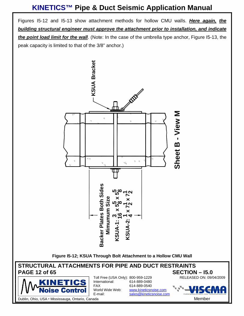
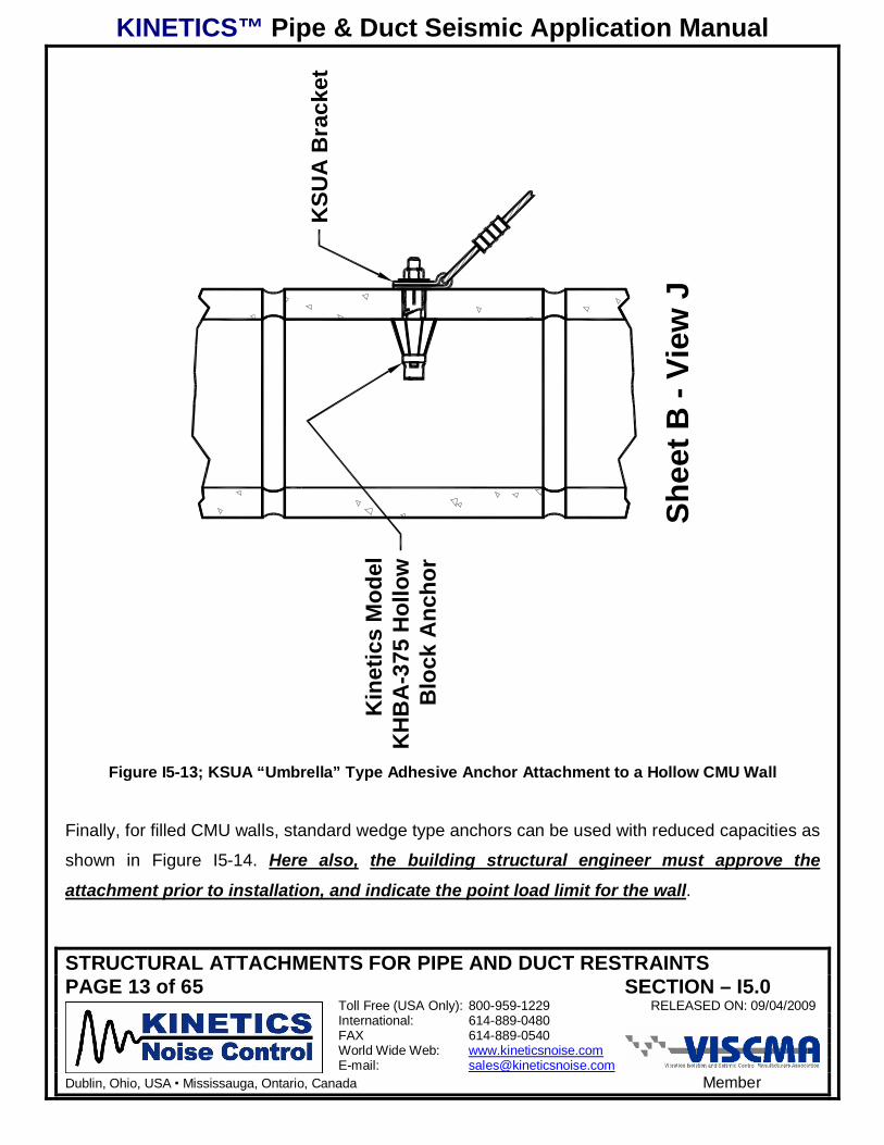
Figures I5-12 and I5-13 show attachment methods for hollow CMU walls. Here again, the
building structural engineer must approve the attachment prior to installation, and indicate
the point load limit for the wall. (Note: In the case of the umbrella type anchor, Figure I5-13, the
peak capacity is limited to that of the 3/8” anchor.)
Shee
t B -
View
M
KSU
A B
rack
etB
acke
r Pla
tes
Bot
h Si
des
Mim
umum
Siz
e
KSU
A-1
:3 16
x 5
5 8 x 5
5 8K
SUA
-2:1 4 x
71 2 x
71 2
Figure I5-12; KSUA Through Bolt Attachment to a Hollow CMU Wall
KINETICS™ Pipe & Duct Seismic Application Manual
STRUCTURAL ATTACHMENTS FOR PIPE AND DUCT RESTRAINTSPAGE 13 of 65 SECTION – I5.0
Toll Free (USA Only): 800-959-1229 RELEASED ON: 09/04/2009International: 614-889-0480FAX 614-889-0540World Wide Web: www.kineticsnoise.comE-mail: [email protected]
Dublin, Ohio, USA Mississauga, Ontario, Canada Member
Shee
t B -
View
J
KSU
A B
rack
et
Kin
etic
s M
odel
KH
BA
-375
Hol
low
Blo
ck A
ncho
r
Figure I5-13; KSUA “Umbrella” Type Adhesive Anchor Attachment to a Hollow CMU Wall
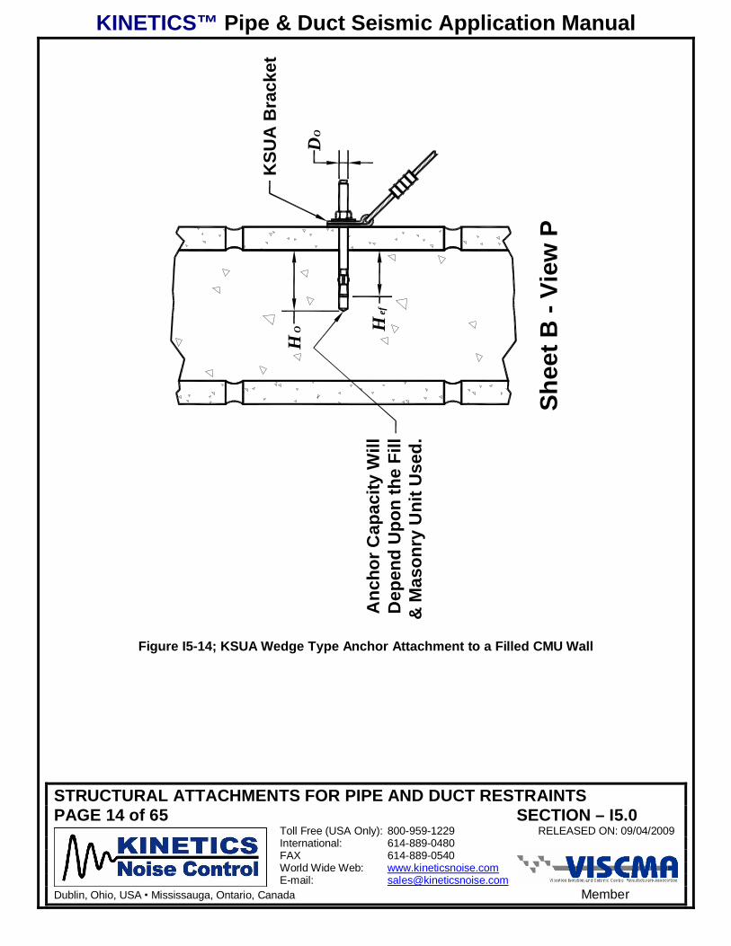
Finally, for filled CMU walls, standard wedge type anchors can be used with reduced capacities as
shown in Figure I5-14. Here also, the building structural engineer must approve the
attachment prior to installation, and indicate the point load limit for the wall.
KINETICS™ Pipe & Duct Seismic Application Manual
STRUCTURAL ATTACHMENTS FOR PIPE AND DUCT RESTRAINTSPAGE 14 of 65 SECTION – I5.0
Toll Free (USA Only): 800-959-1229 RELEASED ON: 09/04/2009International: 614-889-0480FAX 614-889-0540World Wide Web: www.kineticsnoise.comE-mail: [email protected]
Dublin, Ohio, USA Mississauga, Ontario, Canada Member
Shee
t B -
View
P
KSU
A B
rack
et
DO
HO H
efA
ncho
r Cap
acity
Will
Dep
end
Upo
n th
e Fi
ll&
Mas
onry
Uni
t Use
d.
Figure I5-14; KSUA Wedge Type Anchor Attachment to a Filled CMU Wall
KINETICS™ Pipe & Duct Seismic Application Manual
STRUCTURAL ATTACHMENTS FOR PIPE AND DUCT RESTRAINTSPAGE 15 of 65 SECTION – I5.0
Toll Free (USA Only): 800-959-1229 RELEASED ON: 09/04/2009International: 614-889-0480FAX 614-889-0540World Wide Web: www.kineticsnoise.comE-mail: [email protected]
Dublin, Ohio, USA Mississauga, Ontario, Canada Member
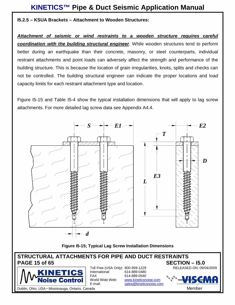
I5.2.5 – KSUA Brackets – Attachment to Wooden Structures:
Attachment of seismic or wind restraints to a wooden structure requires careful
coordination with the building structural engineer. While wooden structures tend to perform
better during an earthquake than their concrete, masonry, or steel counterparts, individual
restraint attachments and point loads can adversely affect the strength and performance of the
building structure. This is because the location of grain irregularities, knots, splits and checks can
not be controlled. The building structural engineer can indicate the proper locations and load
capacity limits for each restraint attachment type and location.
Figure I5-15 and Table I5-4 show the typical installation dimensions that will apply to lag screw
attachments. For more detailed lag screw data see Appendix A4.4.
S E1
D
E3
TE2
d
L
Figure I5-15; Typical Lag Screw Installation Dimensions
KINETICS™ Pipe & Duct Seismic Application Manual
STRUCTURAL ATTACHMENTS FOR PIPE AND DUCT RESTRAINTSPAGE 16 of 65 SECTION – I5.0
Toll Free (USA Only): 800-959-1229 RELEASED ON: 09/04/2009International: 614-889-0480FAX 614-889-0540World Wide Web: www.kineticsnoise.comE-mail: [email protected]
Dublin, Ohio, USA Mississauga, Ontario, Canada Member
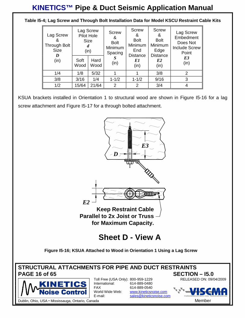
Table I5-4; Lag Screw and Through Bolt Installation Data for Model KSCU Restraint Cable Kits
Lag ScrewPilot Hole
Sized
(in)
Lag Screw&
Through BoltSize
D(in) Soft
WoodHardWood
Screw&
BoltMinimumSpacing
S(in)
Screw&
BoltMinimum
EndDistance
E1(in)
Screw&
BoltMinimum
EdgeDistance
E2(in)
Lag ScrewEmbedment
Does NotInclude Screw
PointE3(in)
1/4 1/8 5/32 1 1 3/8 23/8 3/16 1/4 1-1/2 1-1/2 9/16 31/2 15/64 21/64 2 2 3/4 4
KSUA brackets installed in Orientation 1 to structural wood are shown in Figure I5-16 for a lag
screw attachment and Figure I5-17 for a through bolted attachment.
Keep Restraint CableParallel to 2x Joist or Truss
for Maximum Capacity.
E2
DE3
Sheet D - View AFigure I5-16; KSUA Attached to Wood in Orientation 1 Using a Lag Screw
KINETICS™ Pipe & Duct Seismic Application Manual
STRUCTURAL ATTACHMENTS FOR PIPE AND DUCT RESTRAINTSPAGE 17 of 65 SECTION – I5.0
Toll Free (USA Only): 800-959-1229 RELEASED ON: 09/04/2009International: 614-889-0480FAX 614-889-0540World Wide Web: www.kineticsnoise.comE-mail: [email protected]
Dublin, Ohio, USA Mississauga, Ontario, Canada Member
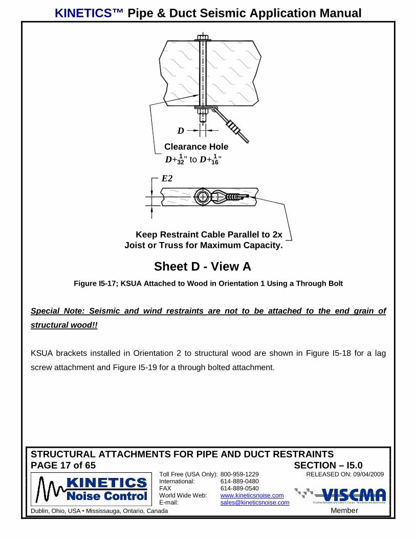
Clearance HoleD+ 1
32" to D+ 116"
D
Sheet D - View A
E2
Keep Restraint Cable Parallel to 2xJoist or Truss for Maximum Capacity.
Figure I5-17; KSUA Attached to Wood in Orientation 1 Using a Through Bolt
Special Note: Seismic and wind restraints are not to be attached to the end grain of
structural wood!!
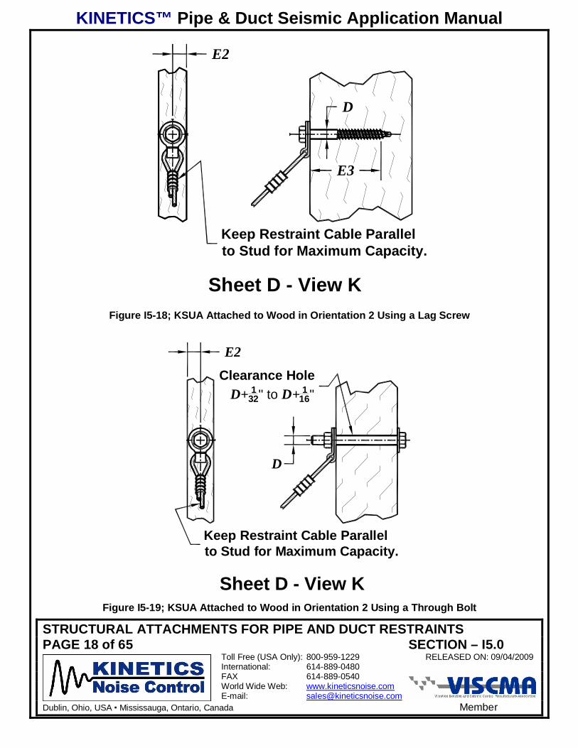
KSUA brackets installed in Orientation 2 to structural wood are shown in Figure I5-18 for a lag
screw attachment and Figure I5-19 for a through bolted attachment.
KINETICS™ Pipe & Duct Seismic Application Manual
STRUCTURAL ATTACHMENTS FOR PIPE AND DUCT RESTRAINTSPAGE 18 of 65 SECTION – I5.0
Toll Free (USA Only): 800-959-1229 RELEASED ON: 09/04/2009International: 614-889-0480FAX 614-889-0540World Wide Web: www.kineticsnoise.comE-mail: [email protected]
Dublin, Ohio, USA Mississauga, Ontario, Canada Member
Keep Restraint Cable Parallelto Stud for Maximum Capacity.
D
E2
E3
Sheet D - View KFigure I5-18; KSUA Attached to Wood in Orientation 2 Using a Lag Screw
Keep Restraint Cable Parallelto Stud for Maximum Capacity.
D
Clearance HoleD+ 1
32" to D+ 116"
E2
Sheet D - View KFigure I5-19; KSUA Attached to Wood in Orientation 2 Using a Through Bolt
KINETICS™ Pipe & Duct Seismic Application Manual
STRUCTURAL ATTACHMENTS FOR PIPE AND DUCT RESTRAINTSPAGE 19 of 65 SECTION – I5.0
Toll Free (USA Only): 800-959-1229 RELEASED ON: 09/04/2009International: 614-889-0480FAX 614-889-0540World Wide Web: www.kineticsnoise.comE-mail: [email protected]
Dublin, Ohio, USA Mississauga, Ontario, Canada Member
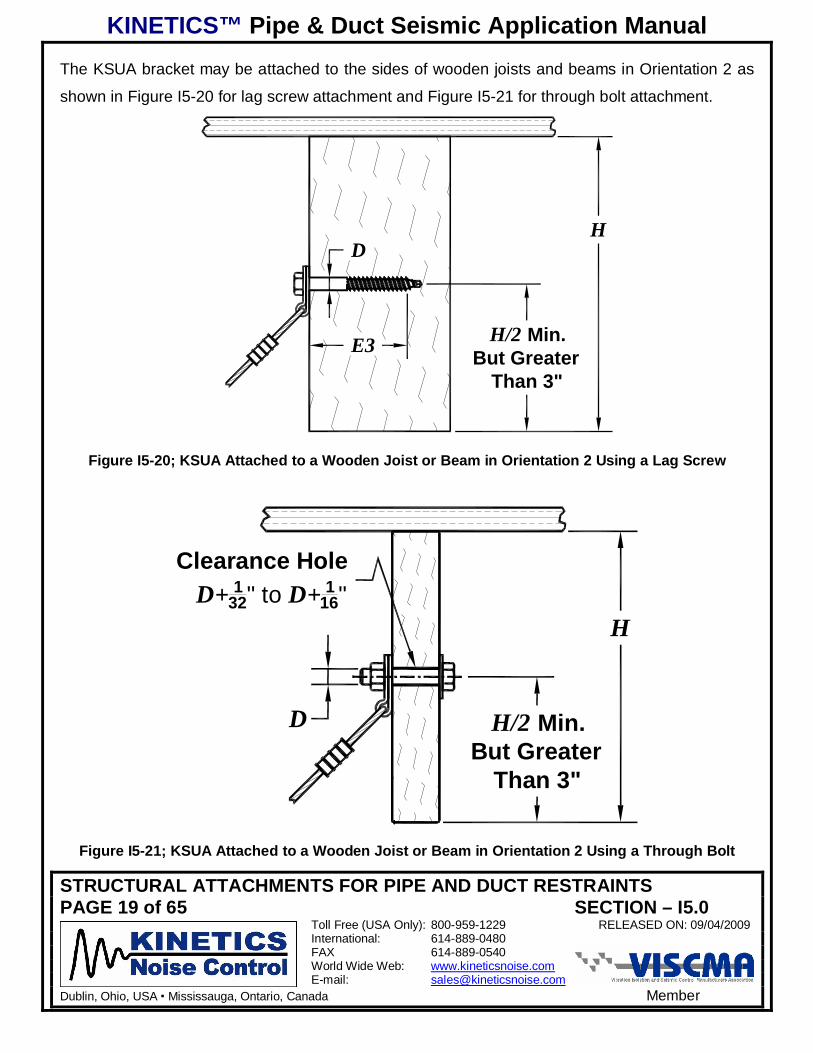
The KSUA bracket may be attached to the sides of wooden joists and beams in Orientation 2 as
shown in Figure I5-20 for lag screw attachment and Figure I5-21 for through bolt attachment.
H
H/2 Min.But Greater
Than 3"
D
E3
Figure I5-20; KSUA Attached to a Wooden Joist or Beam in Orientation 2 Using a Lag Screw
H
H/2 Min.But Greater
Than 3"
D
Clearance HoleD+ 1
32" to D+ 116"
Figure I5-21; KSUA Attached to a Wooden Joist or Beam in Orientation 2 Using a Through Bolt
KINETICS™ Pipe & Duct Seismic Application Manual
STRUCTURAL ATTACHMENTS FOR PIPE AND DUCT RESTRAINTSPAGE 20 of 65 SECTION – I5.0
Toll Free (USA Only): 800-959-1229 RELEASED ON: 09/04/2009International: 614-889-0480FAX 614-889-0540World Wide Web: www.kineticsnoise.comE-mail: [email protected]
Dublin, Ohio, USA Mississauga, Ontario, Canada Member
I5.3 – KSCA Attachment Brackets:
I5.3.1 – KSCA Brackets – Basic Sizes & Installation:
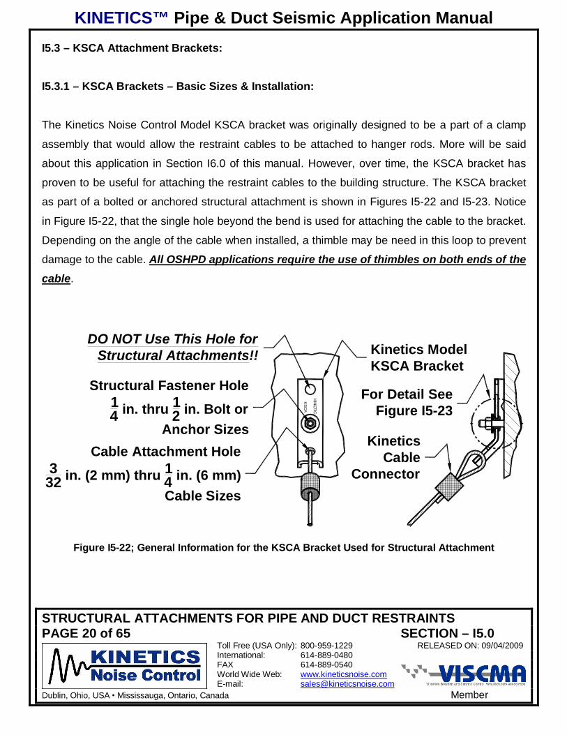
The Kinetics Noise Control Model KSCA bracket was originally designed to be a part of a clamp
assembly that would allow the restraint cables to be attached to hanger rods. More will be said
about this application in Section I6.0 of this manual. However, over time, the KSCA bracket has
proven to be useful for attaching the restraint cables to the building structure. The KSCA bracket
as part of a bolted or anchored structural attachment is shown in Figures I5-22 and I5-23. Notice
in Figure I5-22, that the single hole beyond the bend is used for attaching the cable to the bracket.
Depending on the angle of the cable when installed, a thimble may be need in this loop to prevent
damage to the cable. All OSHPD applications require the use of thimbles on both ends of the
cable.
KINETIC
KS
CA
DO NOT Use This Hole forStructural Attachments!!
Cable Attachment Hole3
32 in. (2 mm) thru 14 in. (6 mm)Cable Sizes
KineticsCable
Connector
For Detail SeeFigure I5-23
Structural Fastener Hole14 in. thru 1
2 in. Bolt orAnchor Sizes
Kinetics ModelKSCA Bracket
Figure I5-22; General Information for the KSCA Bracket Used for Structural Attachment
KINETICS™ Pipe & Duct Seismic Application Manual
STRUCTURAL ATTACHMENTS FOR PIPE AND DUCT RESTRAINTSPAGE 21 of 65 SECTION – I5.0
Toll Free (USA Only): 800-959-1229 RELEASED ON: 09/04/2009International: 614-889-0480FAX 614-889-0540World Wide Web: www.kineticsnoise.comE-mail: [email protected]
Dublin, Ohio, USA Mississauga, Ontario, Canada Member
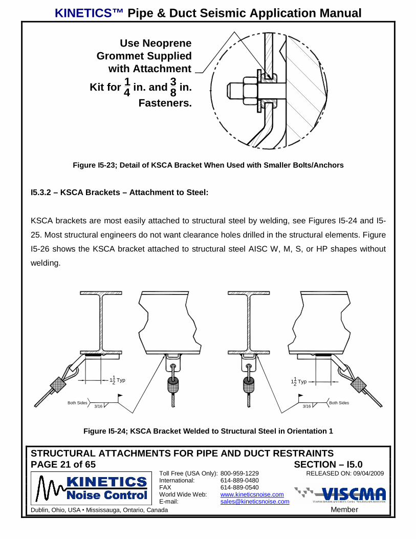
Use NeopreneGrommet Supplied
with Attachment
Kit for 14 in. and 3
8 in.Fasteners.
Figure I5-23; Detail of KSCA Bracket When Used with Smaller Bolts/Anchors
I5.3.2 – KSCA Brackets – Attachment to Steel:
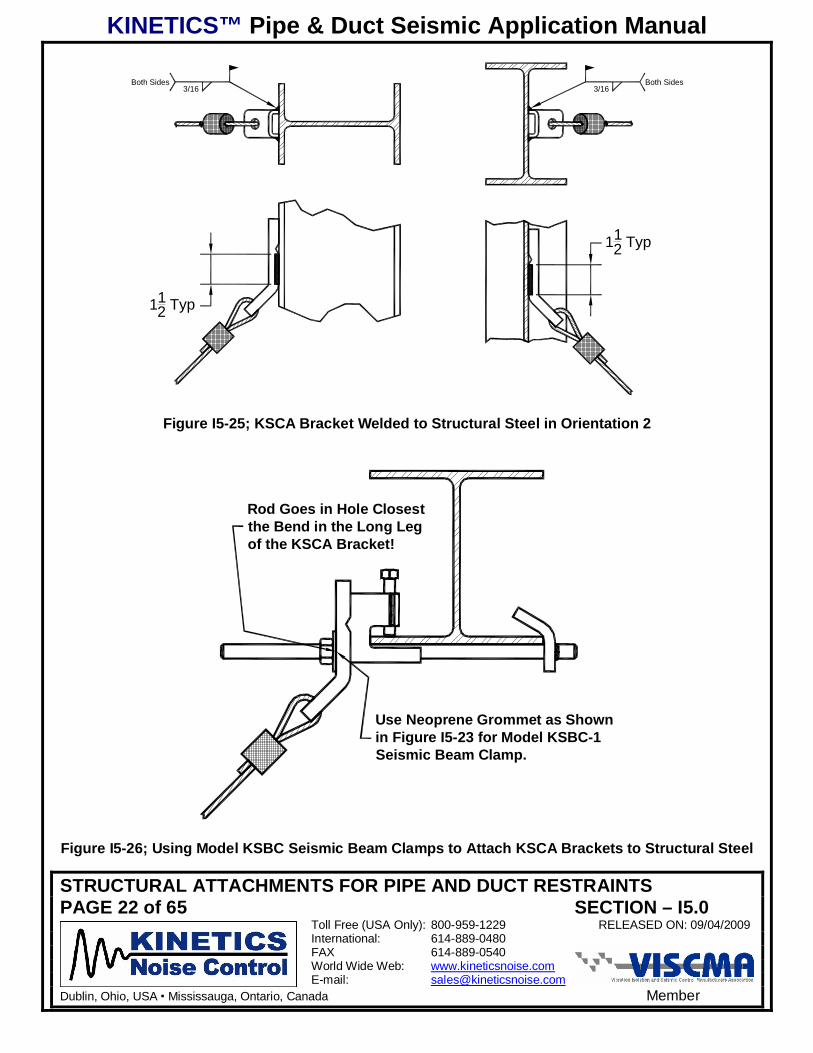
KSCA brackets are most easily attached to structural steel by welding, see Figures I5-24 and I5-
25. Most structural engineers do not want clearance holes drilled in the structural elements. Figure
I5-26 shows the KSCA bracket attached to structural steel AISC W, M, S, or HP shapes without
welding.
Both Sides3/16
Both Sides3/16
112 Typ 11
2 Typ
Figure I5-24; KSCA Bracket Welded to Structural Steel in Orientation 1
KINETICS™ Pipe & Duct Seismic Application Manual
STRUCTURAL ATTACHMENTS FOR PIPE AND DUCT RESTRAINTSPAGE 22 of 65 SECTION – I5.0
Toll Free (USA Only): 800-959-1229 RELEASED ON: 09/04/2009International: 614-889-0480FAX 614-889-0540World Wide Web: www.kineticsnoise.comE-mail: [email protected]
Dublin, Ohio, USA Mississauga, Ontario, Canada Member
Both Sides3/16
Both Sides3/16
112 Typ
112 Typ
Figure I5-25; KSCA Bracket Welded to Structural Steel in Orientation 2
Rod Goes in Hole Closestthe Bend in the Long Legof the KSCA Bracket!
Use Neoprene Grommet as Shownin Figure I5-23 for Model KSBC-1Seismic Beam Clamp.
Figure I5-26; Using Model KSBC Seismic Beam Clamps to Attach KSCA Brackets to Structural Steel
KINETICS™ Pipe & Duct Seismic Application Manual
STRUCTURAL ATTACHMENTS FOR PIPE AND DUCT RESTRAINTSPAGE 23 of 65 SECTION – I5.0
Toll Free (USA Only): 800-959-1229 RELEASED ON: 09/04/2009International: 614-889-0480FAX 614-889-0540World Wide Web: www.kineticsnoise.comE-mail: [email protected]
Dublin, Ohio, USA Mississauga, Ontario, Canada Member
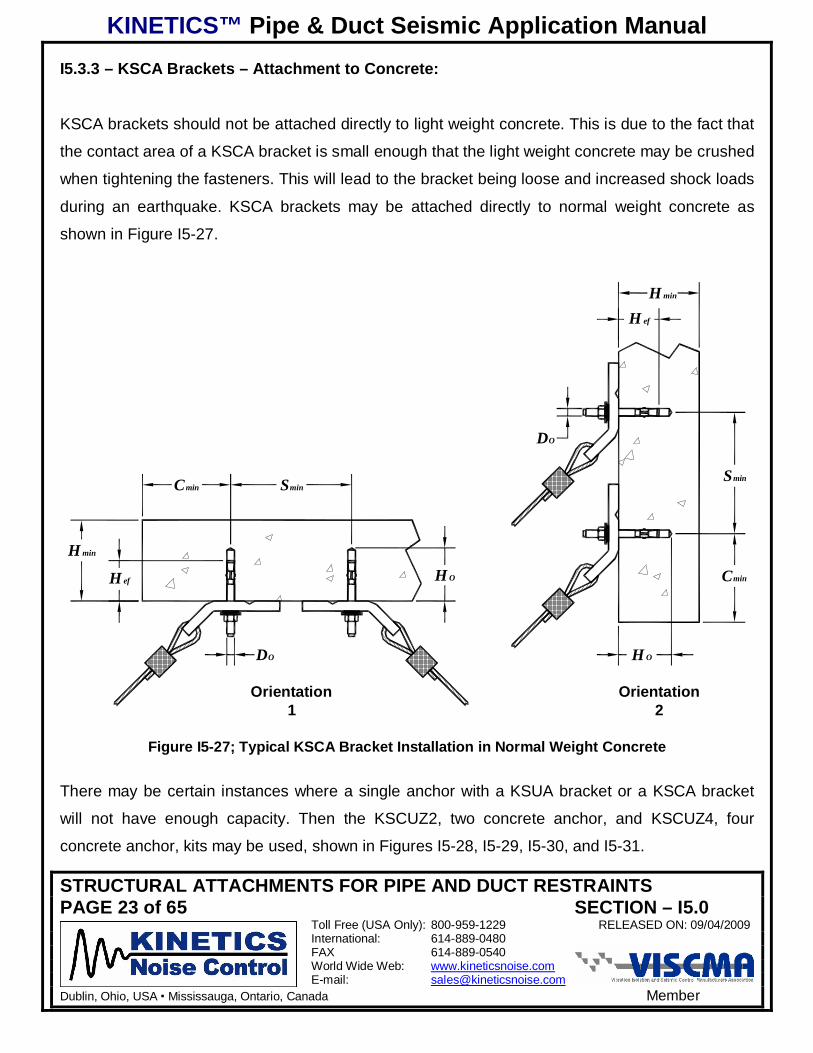
I5.3.3 – KSCA Brackets – Attachment to Concrete:
KSCA brackets should not be attached directly to light weight concrete. This is due to the fact that
the contact area of a KSCA bracket is small enough that the light weight concrete may be crushed
when tightening the fasteners. This will lead to the bracket being loose and increased shock loads
during an earthquake. KSCA brackets may be attached directly to normal weight concrete as
shown in Figure I5-27.
H OH ef
DO
H min
Cmin Smin
DO
Smin
Cmin
H ef
H min
H O
Orientation1
Orientation2
Figure I5-27; Typical KSCA Bracket Installation in Normal Weight Concrete
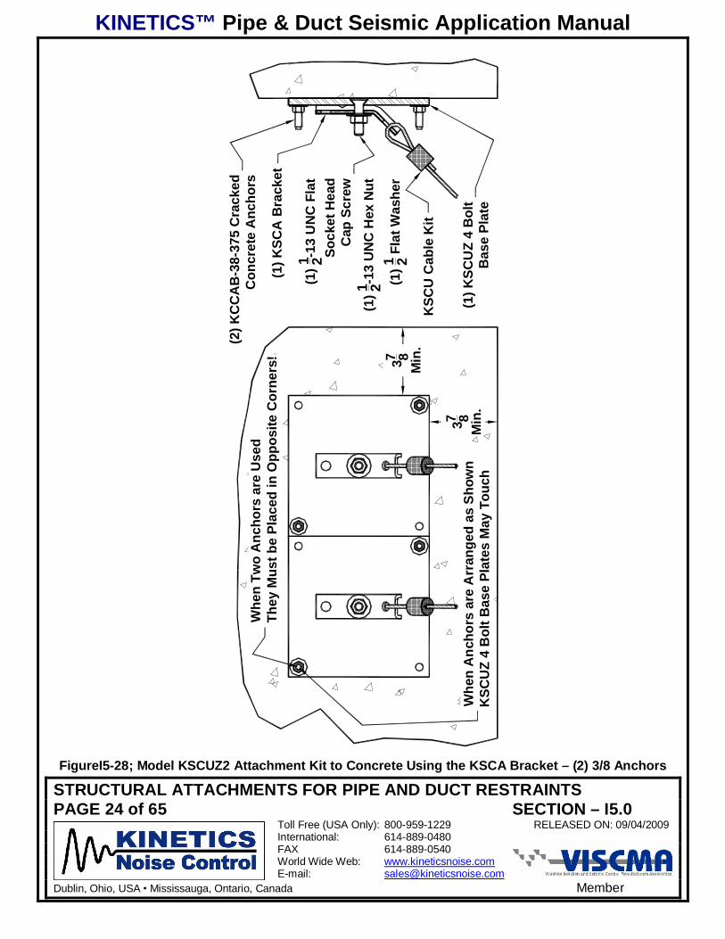
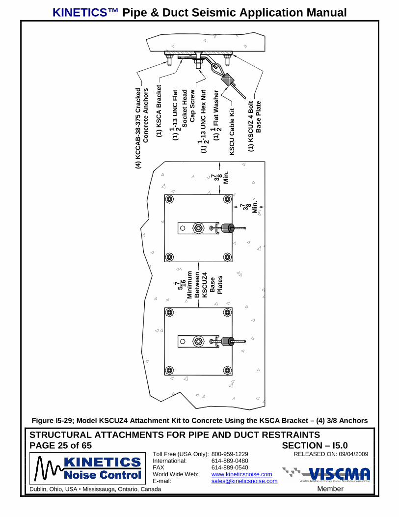
There may be certain instances where a single anchor with a KSUA bracket or a KSCA bracket
will not have enough capacity. Then the KSCUZ2, two concrete anchor, and KSCUZ4, four
concrete anchor, kits may be used, shown in Figures I5-28, I5-29, I5-30, and I5-31.
KINETICS™ Pipe & Duct Seismic Application Manual
STRUCTURAL ATTACHMENTS FOR PIPE AND DUCT RESTRAINTSPAGE 24 of 65 SECTION – I5.0
Toll Free (USA Only): 800-959-1229 RELEASED ON: 09/04/2009International: 614-889-0480FAX 614-889-0540World Wide Web: www.kineticsnoise.comE-mail: [email protected]
Dublin, Ohio, USA Mississauga, Ontario, Canada Member
(1) K
SCU
Z 4
Bol
tB
ase
Plat
e
(1)1 2-1
3 U
NC
Fla
tSo
cket
Hea
dC
ap S
crew
(1)1 2-1
3 U
NC
Hex
Nut
(1)1 2 F
lat W
ashe
r
(1) K
SCA
Bra
cket
(2) K
CC
AB
-38-
375
Cra
cked
Con
cret
e A
ncho
rs
KSC
U C
able
Kit
Whe
n Tw
o A
ncho
rs a
re U
sed
They
Mus
t be
Plac
ed in
Opp
osite
Cor
ners
!
Whe
n A
ncho
rs a
re A
rran
ged
as S
how
nK
SCU
Z 4
Bol
t Bas
e Pl
ates
May
Tou
ch
37 8M
in.
37 8M
in.
FigureI5-28; Model KSCUZ2 Attachment Kit to Concrete Using the KSCA Bracket – (2) 3/8 Anchors
KINETICS™ Pipe & Duct Seismic Application Manual
STRUCTURAL ATTACHMENTS FOR PIPE AND DUCT RESTRAINTSPAGE 25 of 65 SECTION – I5.0
Toll Free (USA Only): 800-959-1229 RELEASED ON: 09/04/2009International: 614-889-0480FAX 614-889-0540World Wide Web: www.kineticsnoise.comE-mail: [email protected]
Dublin, Ohio, USA Mississauga, Ontario, Canada Member
(1) K
SCU
Z 4
Bol
tB
ase
Plat
e
(1)1 2-1
3 U
NC
Fla
tSo
cket
Hea
dC
ap S
crew
(1)1 2-1
3 U
NC
Hex
Nut
(1)1 2 F
lat W
ashe
r
(1) K
SCA
Bra
cket
(4) K
CC
AB
-38-
375
Cra
cked
Con
cret
e A
ncho
rs
KSC
U C
able
Kit
37 8M
in.
37 8M
in.
57 16
Min
imum
Bet
wee
nK
SCU
Z4B
ase
Plat
es
Figure I5-29; Model KSCUZ4 Attachment Kit to Concrete Using the KSCA Bracket – (4) 3/8 Anchors
KINETICS™ Pipe & Duct Seismic Application Manual
STRUCTURAL ATTACHMENTS FOR PIPE AND DUCT RESTRAINTSPAGE 26 of 65 SECTION – I5.0
Toll Free (USA Only): 800-959-1229 RELEASED ON: 09/04/2009International: 614-889-0480FAX 614-889-0540World Wide Web: www.kineticsnoise.comE-mail: [email protected]
Dublin, Ohio, USA Mississauga, Ontario, Canada Member
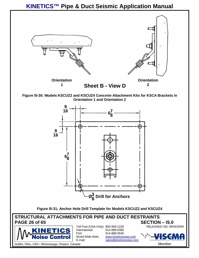
Orientation2
Orientation1 Sheet B - View D
Figure I5-30: Models KSCUZ2 and KSCUZ4 Concrete Attachment Kits for KSCA Brackets inOrientation 1 and Orientation 2
916
916
678
Ø38 Drill for Anchors
678
Figure I5-31; Anchor Hole Drill Template for Models KSCUZ2 and KSCUZ4
KINETICS™ Pipe & Duct Seismic Application Manual
STRUCTURAL ATTACHMENTS FOR PIPE AND DUCT RESTRAINTSPAGE 27 of 65 SECTION – I5.0
Toll Free (USA Only): 800-959-1229 RELEASED ON: 09/04/2009International: 614-889-0480FAX 614-889-0540World Wide Web: www.kineticsnoise.comE-mail: [email protected]
Dublin, Ohio, USA Mississauga, Ontario, Canada Member
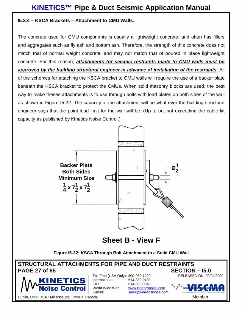
I5.3.4 – KSCA Brackets – Attachment to CMU Walls:
The concrete used for CMU components is usually a lightweight concrete, and often has fillers
and aggregates such as fly ash and bottom ash. Therefore, the strength of this concrete does not
match that of normal weight concrete, and may not match that of poured in place lightweight
concrete. For this reason, attachments for seismic restraints made to CMU walls must be
approved by the building structural engineer in advance of installation of the restraints. All
of the schemes for attaching the KSCA bracket to CMU walls will require the use of a backer plate
beneath the KSCA bracket to protect the CMUs. When solid masonry blocks are used, the best
way to make theses attachments is to use through bolts with load plates on both sides of the wall
as shown in Figure I5-32. The capacity of the attachment will be what ever the building structural
engineer says that the point load limit for the wall will be. (Up to but not exceeding the cable kit
capacity as published by Kinetics Noise Control.)
Sheet B - View F
Ø12
Backer PlateBoth Sides
Minimum Size14 x 71
2 x 712
Figure I5-32; KSCA Through Bolt Attachment to a Solid CMU Wall
KINETICS™ Pipe & Duct Seismic Application Manual
STRUCTURAL ATTACHMENTS FOR PIPE AND DUCT RESTRAINTSPAGE 28 of 65 SECTION – I5.0
Toll Free (USA Only): 800-959-1229 RELEASED ON: 09/04/2009International: 614-889-0480FAX 614-889-0540World Wide Web: www.kineticsnoise.comE-mail: [email protected]
Dublin, Ohio, USA Mississauga, Ontario, Canada Member
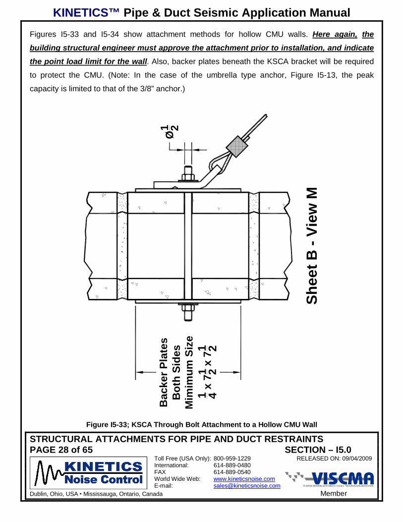
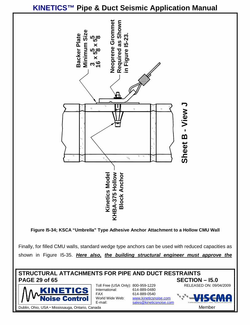
Figures I5-33 and I5-34 show attachment methods for hollow CMU walls. Here again, the
building structural engineer must approve the attachment prior to installation, and indicate
the point load limit for the wall. Also, backer plates beneath the KSCA bracket will be required
to protect the CMU. (Note: In the case of the umbrella type anchor, Figure I5-13, the peak
capacity is limited to that of the 3/8” anchor.)
Shee
t B -
View
M
Ø1 2
Bac
ker P
late
sB
oth
Side
sM
imim
um S
ize
1 4 x 7
1 2 x 7
1 2
Figure I5-33; KSCA Through Bolt Attachment to a Hollow CMU Wall
KINETICS™ Pipe & Duct Seismic Application Manual
STRUCTURAL ATTACHMENTS FOR PIPE AND DUCT RESTRAINTSPAGE 29 of 65 SECTION – I5.0
Toll Free (USA Only): 800-959-1229 RELEASED ON: 09/04/2009International: 614-889-0480FAX 614-889-0540World Wide Web: www.kineticsnoise.comE-mail: [email protected]
Dublin, Ohio, USA Mississauga, Ontario, Canada Member
Shee
t B -
View
J
Kin
etic
s M
odel
KH
BA
-375
Hol
low
Blo
ck A
ncho
r
Bac
ker P
late
Min
imum
Siz
e3 16
x 5
5 8 x 5
5 8
Neo
pren
e G
rom
met
Req
uire
d as
Sho
wn
in F
igur
e I5
-23.
Figure I5-34; KSCA “Umbrella” Type Adhesive Anchor Attachment to a Hollow CMU Wall
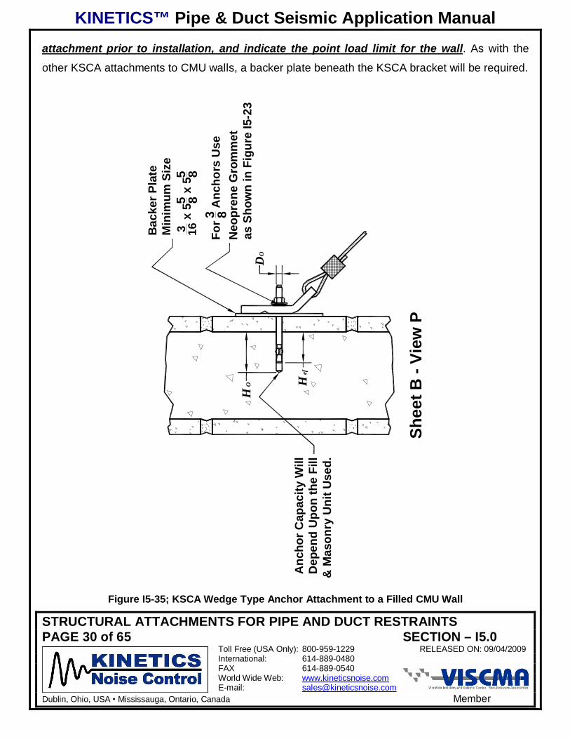
Finally, for filled CMU walls, standard wedge type anchors can be used with reduced capacities as
shown in Figure I5-35. Here also, the building structural engineer must approve the
KINETICS™ Pipe & Duct Seismic Application Manual
STRUCTURAL ATTACHMENTS FOR PIPE AND DUCT RESTRAINTSPAGE 30 of 65 SECTION – I5.0
Toll Free (USA Only): 800-959-1229 RELEASED ON: 09/04/2009International: 614-889-0480FAX 614-889-0540World Wide Web: www.kineticsnoise.comE-mail: [email protected]
Dublin, Ohio, USA Mississauga, Ontario, Canada Member
attachment prior to installation, and indicate the point load limit for the wall. As with the
other KSCA attachments to CMU walls, a backer plate beneath the KSCA bracket will be required.
Shee
t B -
View
P
DO
HO H
efA
ncho
r Cap
acity
Will
Dep
end
Upo
n th
e Fi
ll&
Mas
onry
Uni
t Use
d.
Bac
ker P
late
Min
imum
Siz
e3 16
x 5
5 8 x 5
5 8
For3 8 A
ncho
rs U
seN
eopr
ene
Gro
mm
etas
Sho
wn
in F
igur
e I5
-23
Figure I5-35; KSCA Wedge Type Anchor Attachment to a Filled CMU Wall

KINETICS™ Pipe & Duct Seismic Application Manual
STRUCTURAL ATTACHMENTS FOR PIPE AND DUCT RESTRAINTSPAGE 31 of 65 SECTION – I5.0
Toll Free (USA Only): 800-959-1229 RELEASED ON: 09/04/2009International: 614-889-0480FAX 614-889-0540World Wide Web: www.kineticsnoise.comE-mail: [email protected]
Dublin, Ohio, USA Mississauga, Ontario, Canada Member
I5.3.5 – KSCA Brackets – Attachment to Wooden Structures:
Attachment of seismic or wind restraints to a wooden structure requires careful
coordination with the building structural engineer. While wooden structures tend to perform
better during an earthquake than their concrete, masonry, or steel counterparts, individual
restraint attachments and point loads can adversely affect the strength and performance of the
building structure. This is because the location of grain irregularities, knots, splits and checks can
not be controlled. The building structural engineer can indicate the proper locations and load
capacity limits for each restraint attachment type and location. Figure I5-15 and Table I5-4 show
the typical installation dimensions that will apply to lag screw attachments. For more detailed lag
screw data see Appendix A4.4. KSCA brackets used fro attachment to wood applications will
require steel backer plates beneath the KSCA bracket to prevent damage to the wood!KSCA brackets installed in Orientation 1 to structural wood are shown in Figure I5-36 for a lag
screw attachment and Figure I5-37 for a through bolted attachment.
Keep Restraint CableParallel to 2x Joist or Truss
for Maximum Capacity.
E3
D
For 14 in. & 3
8 in.Lag Screws SeeFigure I5-23
E2
Backer PlateMinimum Size3
16 x 112 x 55
8
Figure I5-36; KSCA Attached to Wood in Orientation 1 Using a Lag Screw
KINETICS™ Pipe & Duct Seismic Application Manual
STRUCTURAL ATTACHMENTS FOR PIPE AND DUCT RESTRAINTSPAGE 32 of 65 SECTION – I5.0
Toll Free (USA Only): 800-959-1229 RELEASED ON: 09/04/2009International: 614-889-0480FAX 614-889-0540World Wide Web: www.kineticsnoise.comE-mail: [email protected]
Dublin, Ohio, USA Mississauga, Ontario, Canada Member
Clearance HoleD+ 1
32" to D+ 116"
D
Keep Restraint CableParallel to 2x Joist or Truss
for Maximum Capacity.
For 14 in. & 3
8 in. Bolts See Figure I5-23
E2
Backer PlateMinimum Size3
16 x 112 x 55
8
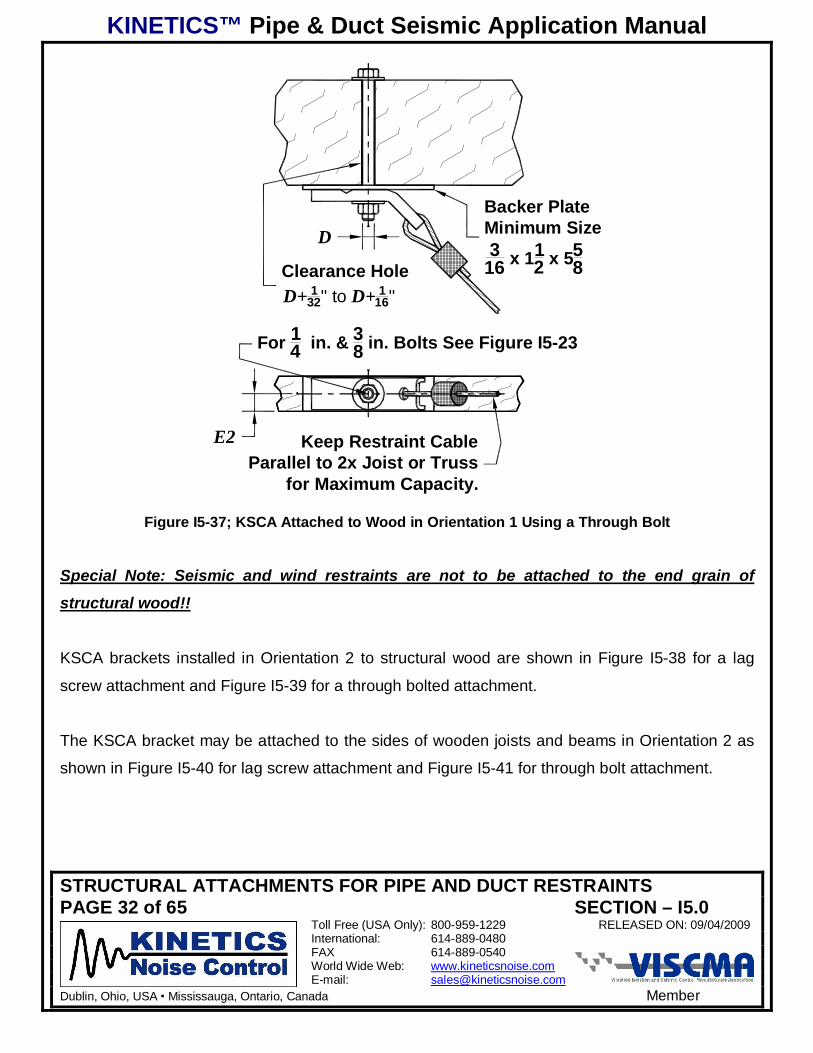
Figure I5-37; KSCA Attached to Wood in Orientation 1 Using a Through Bolt
Special Note: Seismic and wind restraints are not to be attached to the end grain of
structural wood!!
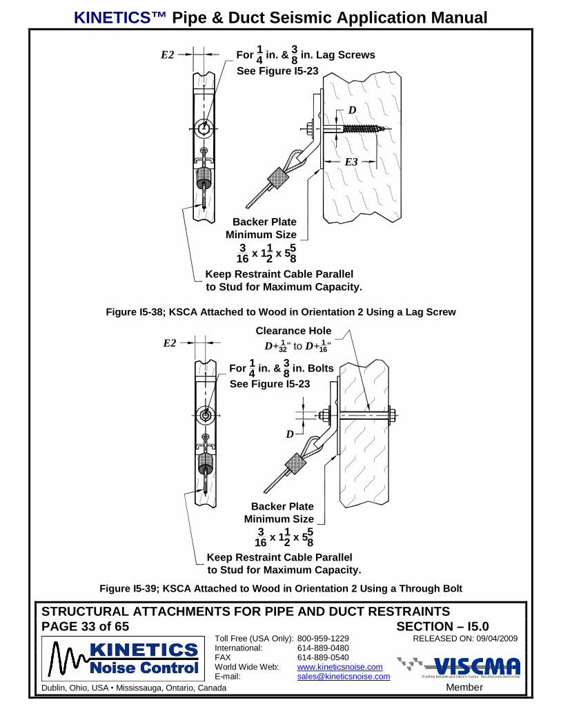
KSCA brackets installed in Orientation 2 to structural wood are shown in Figure I5-38 for a lag
screw attachment and Figure I5-39 for a through bolted attachment.
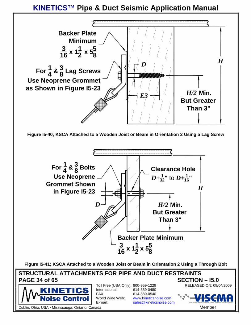
The KSCA bracket may be attached to the sides of wooden joists and beams in Orientation 2 as
shown in Figure I5-40 for lag screw attachment and Figure I5-41 for through bolt attachment.
KINETICS™ Pipe & Duct Seismic Application Manual
STRUCTURAL ATTACHMENTS FOR PIPE AND DUCT RESTRAINTSPAGE 33 of 65 SECTION – I5.0
Toll Free (USA Only): 800-959-1229 RELEASED ON: 09/04/2009International: 614-889-0480FAX 614-889-0540World Wide Web: www.kineticsnoise.comE-mail: [email protected]
Dublin, Ohio, USA Mississauga, Ontario, Canada Member
Keep Restraint Cable Parallelto Stud for Maximum Capacity.
E3
D
E2
Backer PlateMinimum Size
316 x 11
2 x 558
For 14 in. & 3
8 in. Lag ScrewsSee Figure I5-23
Figure I5-38; KSCA Attached to Wood in Orientation 2 Using a Lag Screw
D
Clearance HoleD+ 1
32" to D+ 116"E2
For 14 in. & 3
8 in. BoltsSee Figure I5-23
Backer PlateMinimum Size
316 x 11
2 x 558
Keep Restraint Cable Parallelto Stud for Maximum Capacity.
Figure I5-39; KSCA Attached to Wood in Orientation 2 Using a Through Bolt
KINETICS™ Pipe & Duct Seismic Application Manual
STRUCTURAL ATTACHMENTS FOR PIPE AND DUCT RESTRAINTSPAGE 34 of 65 SECTION – I5.0
Toll Free (USA Only): 800-959-1229 RELEASED ON: 09/04/2009International: 614-889-0480FAX 614-889-0540World Wide Web: www.kineticsnoise.comE-mail: [email protected]
Dublin, Ohio, USA Mississauga, Ontario, Canada Member
H
H/2 Min.But Greater
Than 3"
E3
DFor 1
4 & 38 Lag Screws
Use Neoprene Grommetas Shown in Figure I5-23
Backer PlateMinimum
316 x 11
2 x 558
Figure I5-40; KSCA Attached to a Wooden Joist or Beam in Orientation 2 Using a Lag Screw
D
Clearance HoleD+ 1
32" to D+ 116"
Backer Plate Minimum3
16 x 112 x 55
8
For 14 & 3
8 BoltsUse Neoprene
Grommet Shownin FIgure I5-23 H
H/2 Min.But Greater
Than 3"
Figure I5-41; KSCA Attached to a Wooden Joist or Beam in Orientation 2 Using a Through Bolt
KINETICS™ Pipe & Duct Seismic Application Manual
STRUCTURAL ATTACHMENTS FOR PIPE AND DUCT RESTRAINTSPAGE 35 of 65 SECTION – I5.0
Toll Free (USA Only): 800-959-1229 RELEASED ON: 09/04/2009International: 614-889-0480FAX 614-889-0540World Wide Web: www.kineticsnoise.comE-mail: [email protected]
Dublin, Ohio, USA Mississauga, Ontario, Canada Member
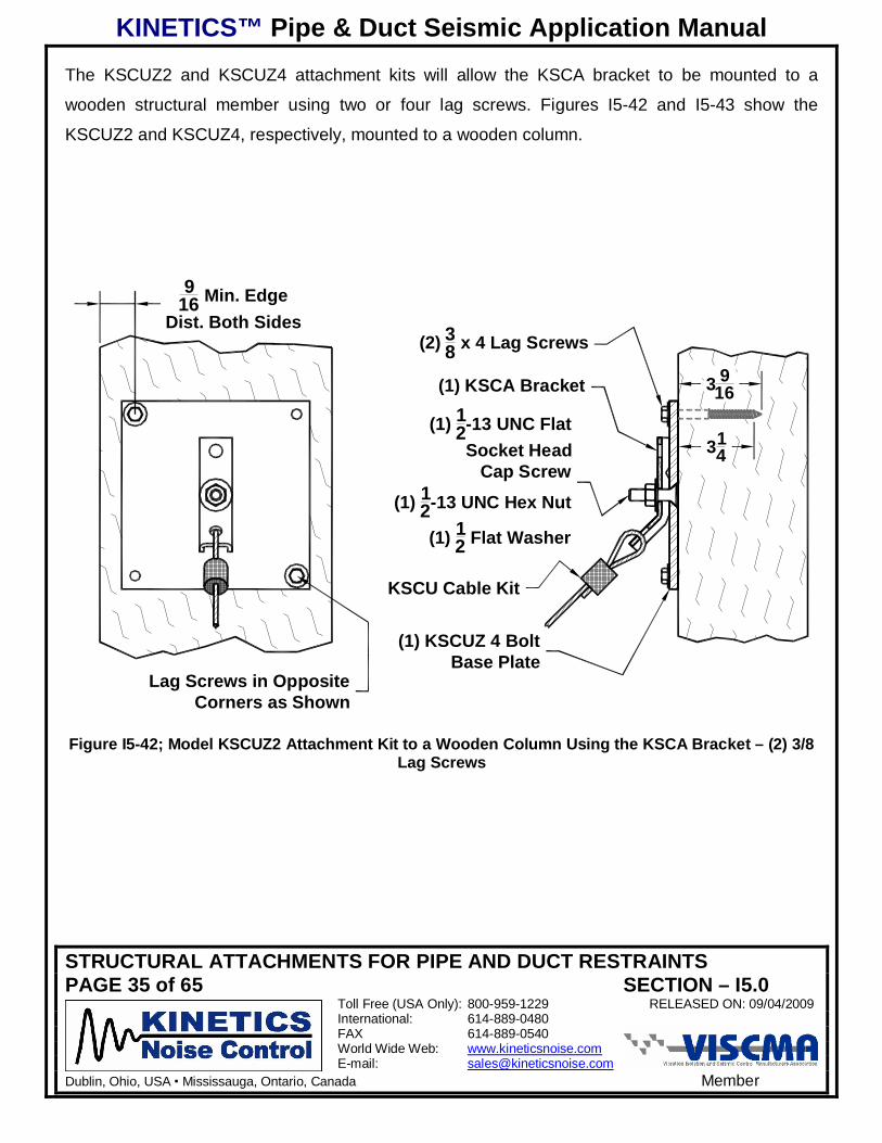
The KSCUZ2 and KSCUZ4 attachment kits will allow the KSCA bracket to be mounted to a
wooden structural member using two or four lag screws. Figures I5-42 and I5-43 show the
KSCUZ2 and KSCUZ4, respectively, mounted to a wooden column.
916 Min. Edge
Dist. Both Sides
(1) KSCUZ 4 BoltBase Plate
(1) 12-13 UNC Flat
Socket HeadCap Screw
(1) 12-13 UNC Hex Nut
(1) 12 Flat Washer
(1) KSCA Bracket
(2) 38 x 4 Lag Screws
KSCU Cable Kit
Lag Screws in OppositeCorners as Shown
314
3 916
Figure I5-42; Model KSCUZ2 Attachment Kit to a Wooden Column Using the KSCA Bracket – (2) 3/8Lag Screws
KINETICS™ Pipe & Duct Seismic Application Manual
STRUCTURAL ATTACHMENTS FOR PIPE AND DUCT RESTRAINTSPAGE 36 of 65 SECTION – I5.0
Toll Free (USA Only): 800-959-1229 RELEASED ON: 09/04/2009International: 614-889-0480FAX 614-889-0540World Wide Web: www.kineticsnoise.comE-mail: [email protected]
Dublin, Ohio, USA Mississauga, Ontario, Canada Member
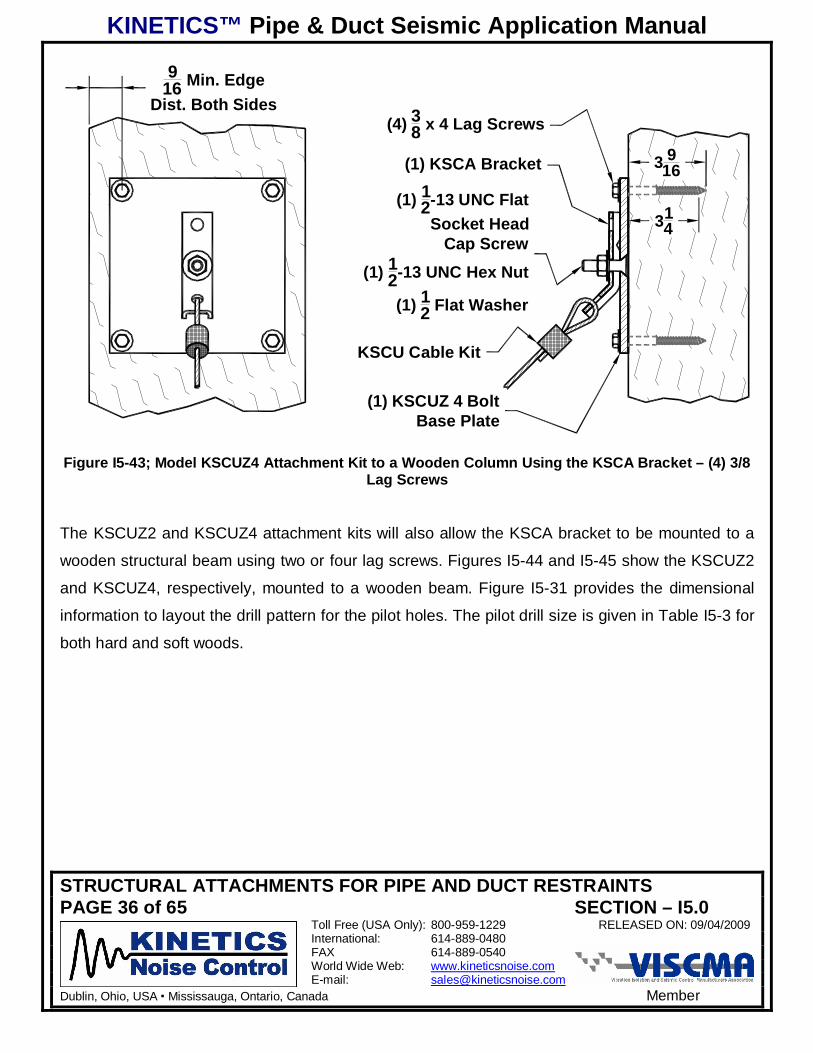
(1) KSCUZ 4 BoltBase Plate
(1) 12-13 UNC Flat
Socket HeadCap Screw
(1) 12-13 UNC Hex Nut
(1) 12 Flat Washer
(1) KSCA Bracket
(4) 38 x 4 Lag Screws
KSCU Cable Kit
314
3 916
916 Min. Edge
Dist. Both Sides
Figure I5-43; Model KSCUZ4 Attachment Kit to a Wooden Column Using the KSCA Bracket – (4) 3/8Lag Screws
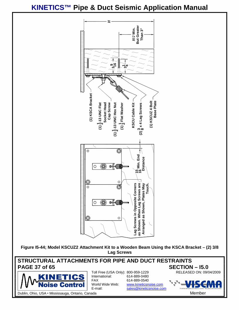
The KSCUZ2 and KSCUZ4 attachment kits will also allow the KSCA bracket to be mounted to a
wooden structural beam using two or four lag screws. Figures I5-44 and I5-45 show the KSCUZ2
and KSCUZ4, respectively, mounted to a wooden beam. Figure I5-31 provides the dimensional
information to layout the drill pattern for the pilot holes. The pilot drill size is given in Table I5-3 for
both hard and soft woods.
KINETICS™ Pipe & Duct Seismic Application Manual
STRUCTURAL ATTACHMENTS FOR PIPE AND DUCT RESTRAINTSPAGE 37 of 65 SECTION – I5.0
Toll Free (USA Only): 800-959-1229 RELEASED ON: 09/04/2009International: 614-889-0480FAX 614-889-0540World Wide Web: www.kineticsnoise.comE-mail: [email protected]
Dublin, Ohio, USA Mississauga, Ontario, Canada Member
(1) K
SCU
Z 4
Bol
tB
ase
Plat
e
(2)3 8 x
4 L
ag S
crew
s
KSC
U C
able
Kit
(1)1 2-1
3 U
NC
Fla
tSo
cket
Hea
dC
ap S
crew
(1)1 2-1
3 U
NC
Hex
Nut
(1)1 2 F
lat W
ashe
r
(1) K
SCA
Bra
cket
31 439 16
Lag
Scre
ws
in O
ppos
ite C
orne
rsas
Sho
wn.
Whe
n La
g Sc
rew
s ar
eA
rran
ged
as S
how
n, P
late
s M
ayTo
uch.
15 16 M
in. E
ndD
ista
nce
H
H/2
Min
.B
ut G
reat
erTh
an 3
"
Figure I5-44; Model KSCUZ2 Attachment Kit to a Wooden Beam Using the KSCA Bracket – (2) 3/8Lag Screws

KINETICS™ Pipe & Duct Seismic Application Manual
STRUCTURAL ATTACHMENTS FOR PIPE AND DUCT RESTRAINTSPAGE 38 of 65 SECTION – I5.0
Toll Free (USA Only): 800-959-1229 RELEASED ON: 09/04/2009International: 614-889-0480FAX 614-889-0540World Wide Web: www.kineticsnoise.comE-mail: [email protected]
Dublin, Ohio, USA Mississauga, Ontario, Canada Member
(1) K
SCU
Z 4
Bol
tB
ase
Plat
e
(2)3 8 x
4 L
ag S
crew
s
KSC
U C
able
Kit
(1)1 2-1
3 U
NC
Fla
tSo
cket
Hea
dC
ap S
crew
(1)1 2-1
3 U
NC
Hex
Nut
(1)1 2 F
lat W
ashe
r
(1) K
SCA
Bra
cket
31 439 16
15 16 M
in. E
ndD
ista
nce
3 8 Min
. Dis
tanc
e B
etw
een
KSC
UZ
4 B
ase
Plat
es
H
H/2
Min
.B
ut G
reat
erTh
an 3
"
Figure I5-45; Model KSCUZ4 Attachment Kit to a Wooden Beam Using the KSCA Bracket – (4) 3/8Lag Screws
KINETICS™ Pipe & Duct Seismic Application Manual
STRUCTURAL ATTACHMENTS FOR PIPE AND DUCT RESTRAINTSPAGE 39 of 65 SECTION – I5.0
Toll Free (USA Only): 800-959-1229 RELEASED ON: 09/04/2009International: 614-889-0480FAX 614-889-0540World Wide Web: www.kineticsnoise.comE-mail: [email protected]
Dublin, Ohio, USA Mississauga, Ontario, Canada Member
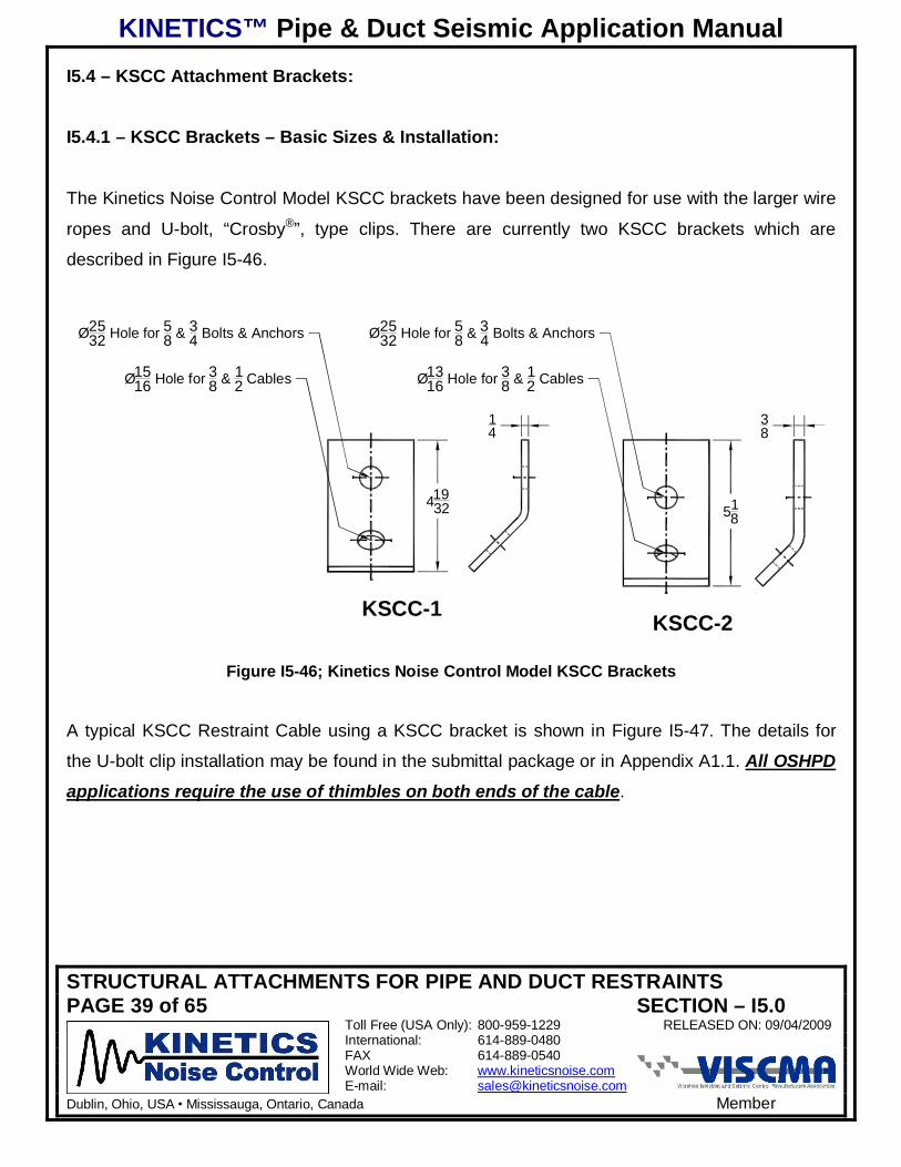
I5.4 – KSCC Attachment Brackets:
I5.4.1 – KSCC Brackets – Basic Sizes & Installation:
The Kinetics Noise Control Model KSCC brackets have been designed for use with the larger wire
ropes and U-bolt, “Crosby®”, type clips. There are currently two KSCC brackets which are
described in Figure I5-46.
14
41932 51
8
38
Ø1316 Hole for 3
8 & 12 Cables
Ø2532 Hole for 5
8 & 34 Bolts & Anchors
Ø1516 Hole for 3
8 & 12 Cables
Ø2532 Hole for 5
8 & 34 Bolts & Anchors
KSCC-1 KSCC-2
Figure I5-46; Kinetics Noise Control Model KSCC Brackets
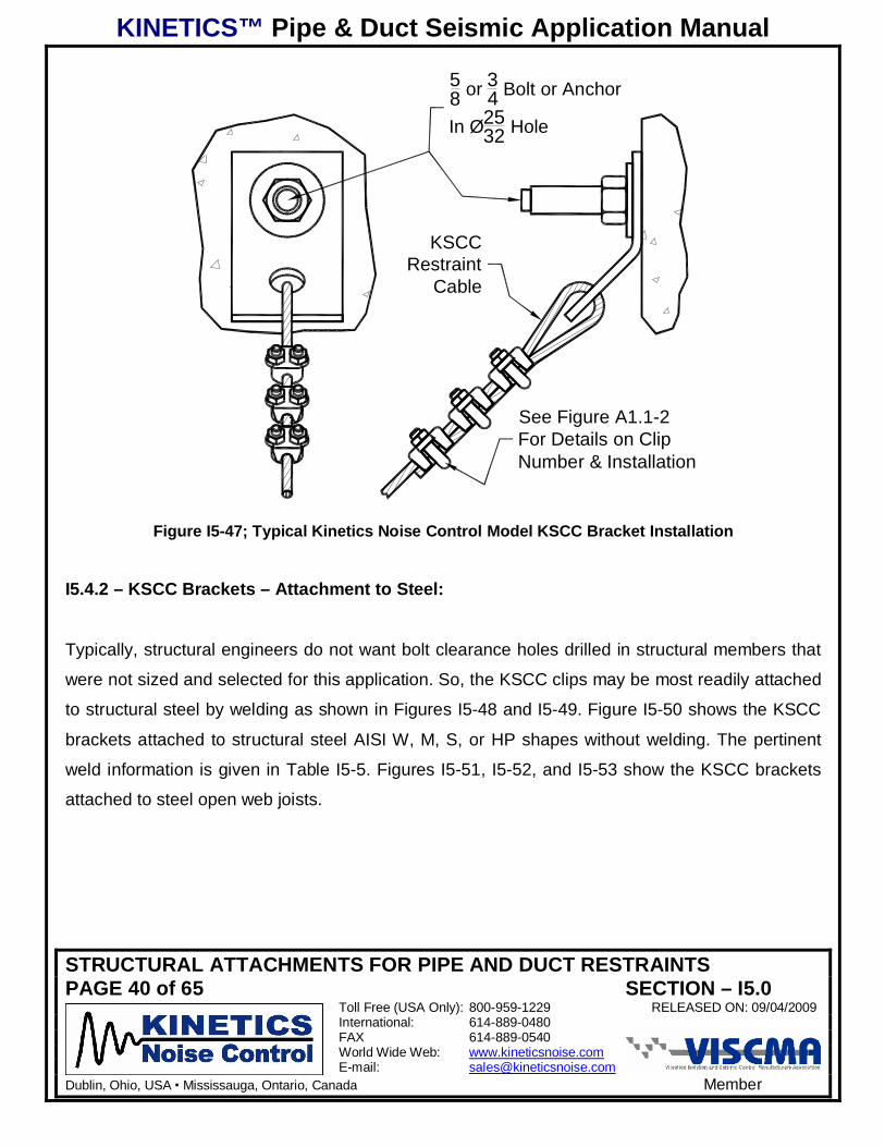
A typical KSCC Restraint Cable using a KSCC bracket is shown in Figure I5-47. The details for
the U-bolt clip installation may be found in the submittal package or in Appendix A1.1. All OSHPDapplications require the use of thimbles on both ends of the cable.
KINETICS™ Pipe & Duct Seismic Application Manual
STRUCTURAL ATTACHMENTS FOR PIPE AND DUCT RESTRAINTSPAGE 40 of 65 SECTION – I5.0
Toll Free (USA Only): 800-959-1229 RELEASED ON: 09/04/2009International: 614-889-0480FAX 614-889-0540World Wide Web: www.kineticsnoise.comE-mail: [email protected]
Dublin, Ohio, USA Mississauga, Ontario, Canada Member
58 or 3
4 Bolt or Anchor
In Ø2532 Hole
KSCCRestraint
Cable
See Figure A1.1-2For Details on ClipNumber & Installation
Figure I5-47; Typical Kinetics Noise Control Model KSCC Bracket Installation
I5.4.2 – KSCC Brackets – Attachment to Steel:
Typically, structural engineers do not want bolt clearance holes drilled in structural members that
were not sized and selected for this application. So, the KSCC clips may be most readily attached
to structural steel by welding as shown in Figures I5-48 and I5-49. Figure I5-50 shows the KSCC
brackets attached to structural steel AISI W, M, S, or HP shapes without welding. The pertinent
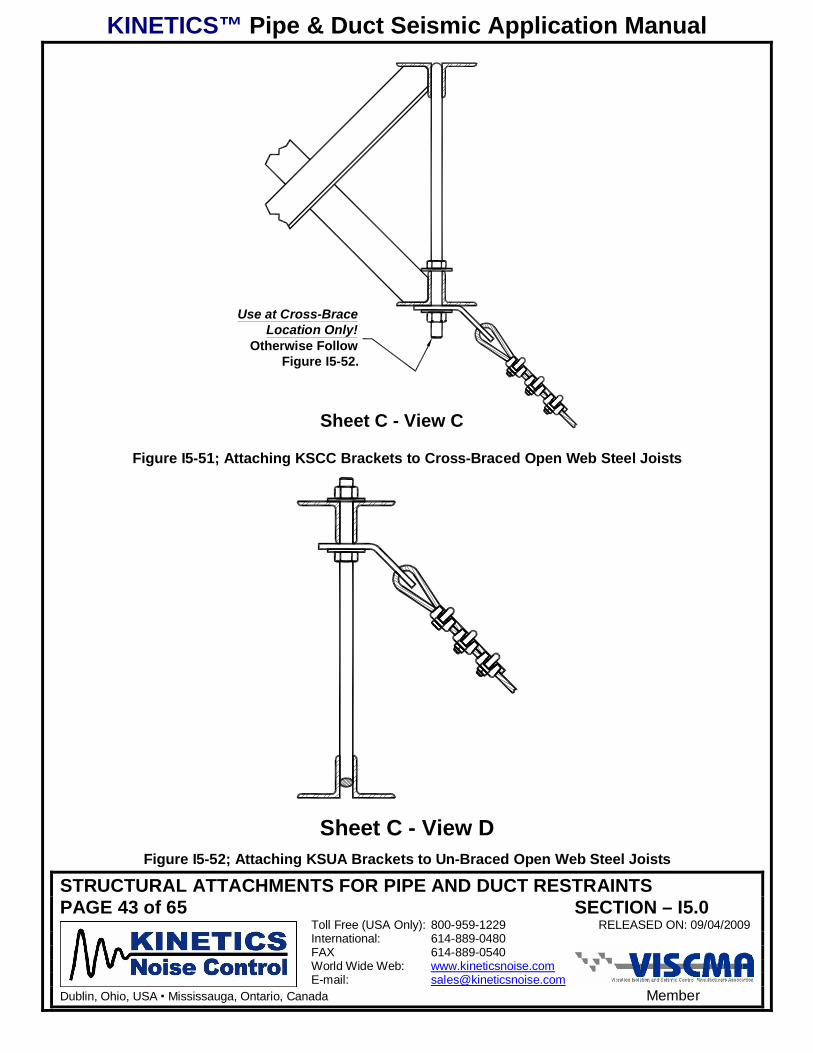
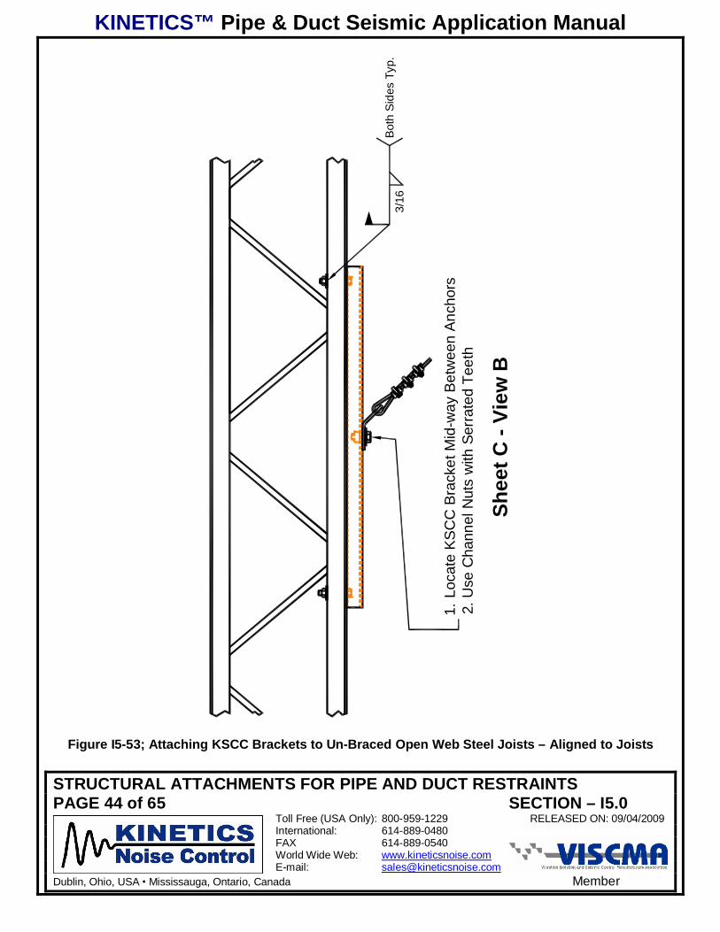
weld information is given in Table I5-5. Figures I5-51, I5-52, and I5-53 show the KSCC brackets
attached to steel open web joists.
KINETICS™ Pipe & Duct Seismic Application Manual
STRUCTURAL ATTACHMENTS FOR PIPE AND DUCT RESTRAINTSPAGE 41 of 65 SECTION – I5.0
Toll Free (USA Only): 800-959-1229 RELEASED ON: 09/04/2009International: 614-889-0480FAX 614-889-0540World Wide Web: www.kineticsnoise.comE-mail: [email protected]
Dublin, Ohio, USA Mississauga, Ontario, Canada Member
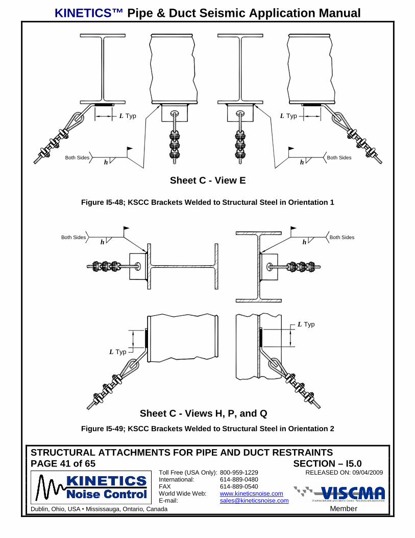
Both SidesBoth Sides
L Typ L Typ
h h
Sheet C - View E
Figure I5-48; KSCC Brackets Welded to Structural Steel in Orientation 1
L Typ
L Typ
Both SidesBoth Sidesh h
Sheet C - Views H, P, and QFigure I5-49; KSCC Brackets Welded to Structural Steel in Orientation 2
KINETICS™ Pipe & Duct Seismic Application Manual
STRUCTURAL ATTACHMENTS FOR PIPE AND DUCT RESTRAINTSPAGE 42 of 65 SECTION – I5.0
Toll Free (USA Only): 800-959-1229 RELEASED ON: 09/04/2009International: 614-889-0480FAX 614-889-0540World Wide Web: www.kineticsnoise.comE-mail: [email protected]
Dublin, Ohio, USA Mississauga, Ontario, Canada Member
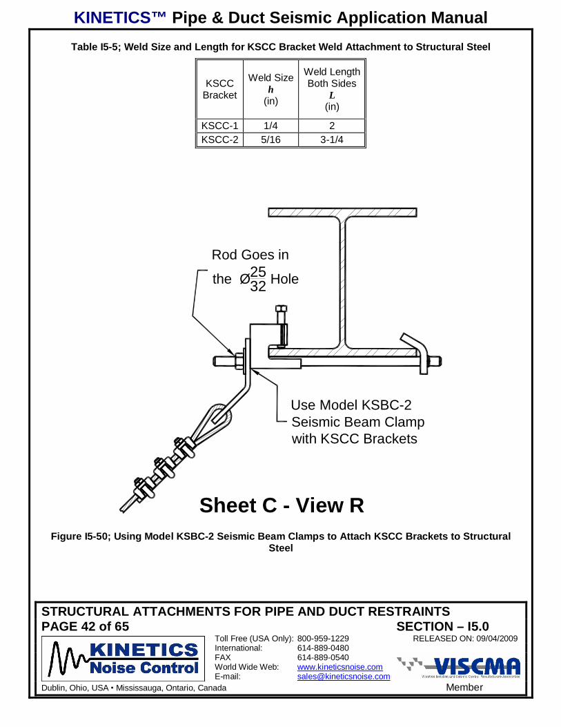
Table I5-5; Weld Size and Length for KSCC Bracket Weld Attachment to Structural Steel
KSCCBracket
Weld Sizeh
(in)
Weld LengthBoth Sides
L(in)
KSCC-1 1/4 2KSCC-2 5/16 3-1/4
Rod Goes in
the Ø2532 Hole
Use Model KSBC-2Seismic Beam Clampwith KSCC Brackets
Sheet C - View RFigure I5-50; Using Model KSBC-2 Seismic Beam Clamps to Attach KSCC Brackets to Structural
Steel
KINETICS™ Pipe & Duct Seismic Application Manual
STRUCTURAL ATTACHMENTS FOR PIPE AND DUCT RESTRAINTSPAGE 43 of 65 SECTION – I5.0
Toll Free (USA Only): 800-959-1229 RELEASED ON: 09/04/2009International: 614-889-0480FAX 614-889-0540World Wide Web: www.kineticsnoise.comE-mail: [email protected]
Dublin, Ohio, USA Mississauga, Ontario, Canada Member
Sheet C - View C
Use at Cross-BraceLocation Only!
Otherwise FollowFigure I5-52.
Figure I5-51; Attaching KSCC Brackets to Cross-Braced Open Web Steel Joists
Sheet C - View DFigure I5-52; Attaching KSUA Brackets to Un-Braced Open Web Steel Joists
KINETICS™ Pipe & Duct Seismic Application Manual
STRUCTURAL ATTACHMENTS FOR PIPE AND DUCT RESTRAINTSPAGE 44 of 65 SECTION – I5.0
Toll Free (USA Only): 800-959-1229 RELEASED ON: 09/04/2009International: 614-889-0480FAX 614-889-0540World Wide Web: www.kineticsnoise.comE-mail: [email protected]
Dublin, Ohio, USA Mississauga, Ontario, Canada Member
Shee
t C -
View
B
Both
Sid
es T
yp.
3/16
1.Lo
cate
KS
CC
Bra
cket
Mid
-way
Bet
wee
n A
ncho
rs2.
Use
Cha
nnel
Nut
s w
ith S
erra
ted
Teet
h
Figure I5-53; Attaching KSCC Brackets to Un-Braced Open Web Steel Joists – Aligned to Joists
KINETICS™ Pipe & Duct Seismic Application Manual
STRUCTURAL ATTACHMENTS FOR PIPE AND DUCT RESTRAINTSPAGE 45 of 65 SECTION – I5.0
Toll Free (USA Only): 800-959-1229 RELEASED ON: 09/04/2009International: 614-889-0480FAX 614-889-0540World Wide Web: www.kineticsnoise.comE-mail: [email protected]
Dublin, Ohio, USA Mississauga, Ontario, Canada Member
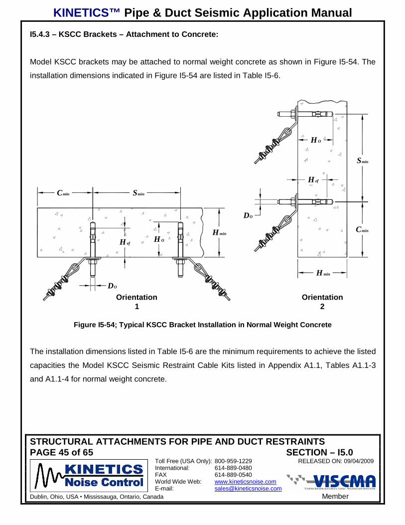
I5.4.3 – KSCC Brackets – Attachment to Concrete:
Model KSCC brackets may be attached to normal weight concrete as shown in Figure I5-54. The
installation dimensions indicated in Figure I5-54 are listed in Table I5-6.
Cmin Smin
H efH O
H min
H ef
H O
Smin
Cmin
H min
DO
Orientation1
Orientation2
DO
Figure I5-54; Typical KSCC Bracket Installation in Normal Weight Concrete
The installation dimensions listed in Table I5-6 are the minimum requirements to achieve the listed
capacities the Model KSCC Seismic Restraint Cable Kits listed in Appendix A1.1, Tables A1.1-3
and A1.1-4 for normal weight concrete.
KINETICS™ Pipe & Duct Seismic Application Manual
STRUCTURAL ATTACHMENTS FOR PIPE AND DUCT RESTRAINTSPAGE 46 of 65 SECTION – I5.0
Toll Free (USA Only): 800-959-1229 RELEASED ON: 09/04/2009International: 614-889-0480FAX 614-889-0540World Wide Web: www.kineticsnoise.comE-mail: [email protected]
Dublin, Ohio, USA Mississauga, Ontario, Canada Member
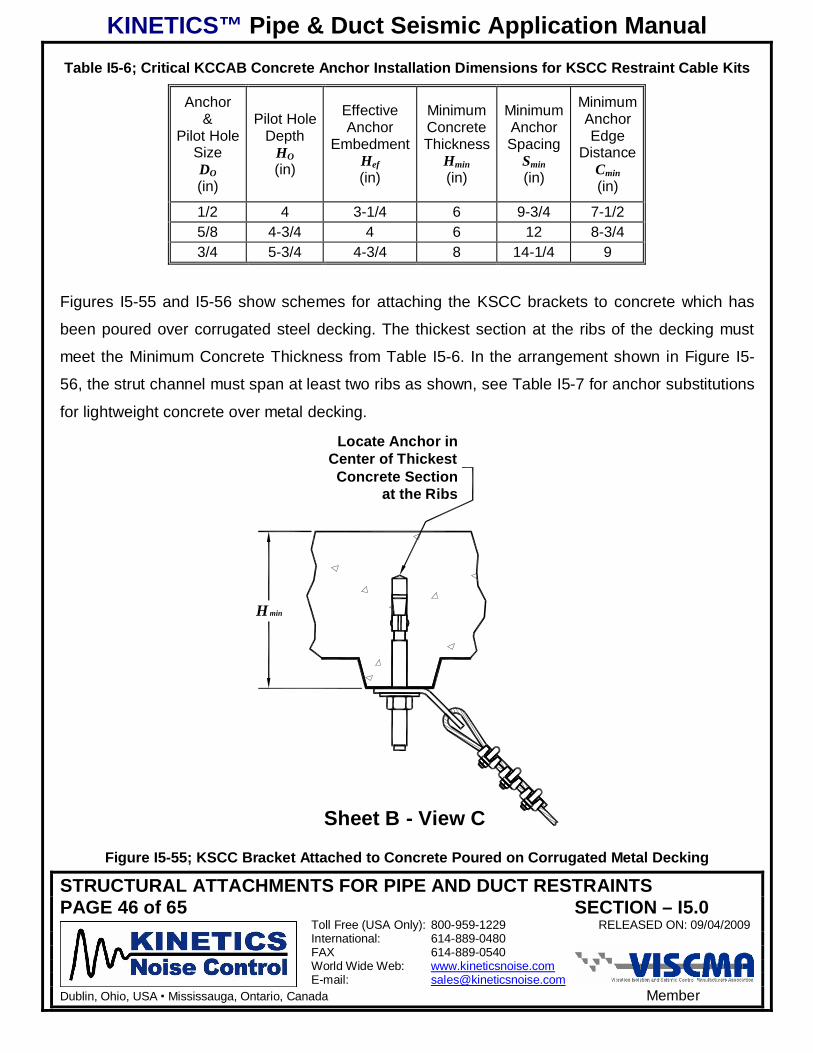
Table I5-6; Critical KCCAB Concrete Anchor Installation Dimensions for KSCC Restraint Cable Kits
Anchor&
Pilot HoleSizeDO(in)
Pilot HoleDepth
HO(in)
EffectiveAnchor
EmbedmentHef(in)
MinimumConcreteThickness
Hmin(in)
MinimumAnchorSpacing
Smin(in)
MinimumAnchorEdge
DistanceCmin(in)
1/2 4 3-1/4 6 9-3/4 7-1/25/8 4-3/4 4 6 12 8-3/43/4 5-3/4 4-3/4 8 14-1/4 9
Figures I5-55 and I5-56 show schemes for attaching the KSCC brackets to concrete which has
been poured over corrugated steel decking. The thickest section at the ribs of the decking must
meet the Minimum Concrete Thickness from Table I5-6. In the arrangement shown in Figure I5-
56, the strut channel must span at least two ribs as shown, see Table I5-7 for anchor substitutions
for lightweight concrete over metal decking.
Sheet B - View C
Locate Anchor inCenter of ThickestConcrete Section
at the Ribs
H min
Figure I5-55; KSCC Bracket Attached to Concrete Poured on Corrugated Metal Decking
KINETICS™ Pipe & Duct Seismic Application Manual
STRUCTURAL ATTACHMENTS FOR PIPE AND DUCT RESTRAINTSPAGE 47 of 65 SECTION – I5.0
Toll Free (USA Only): 800-959-1229 RELEASED ON: 09/04/2009International: 614-889-0480FAX 614-889-0540World Wide Web: www.kineticsnoise.comE-mail: [email protected]
Dublin, Ohio, USA Mississauga, Ontario, Canada Member
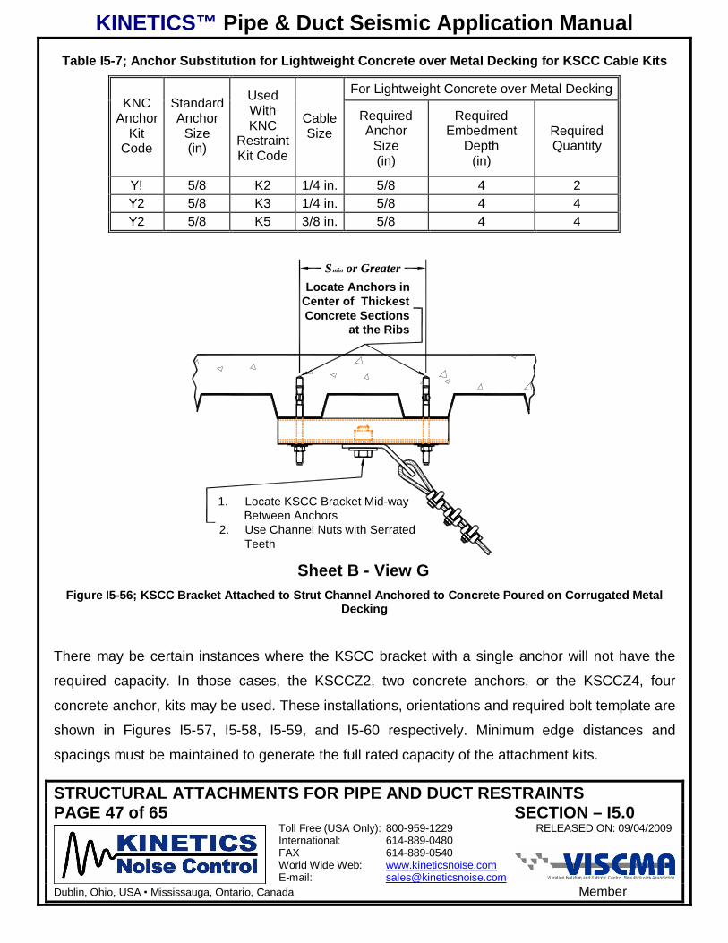
Table I5-7; Anchor Substitution for Lightweight Concrete over Metal Decking for KSCC Cable Kits
For Lightweight Concrete over Metal DeckingKNC
AnchorKit
Code
StandardAnchor
Size(in)
UsedWithKNC
RestraintKit Code
CableSize
RequiredAnchor
Size(in)
RequiredEmbedment
Depth(in)
RequiredQuantity
Y! 5/8 K2 1/4 in. 5/8 4 2Y2 5/8 K3 1/4 in. 5/8 4 4Y2 5/8 K5 3/8 in. 5/8 4 4
Smin or GreaterLocate Anchors in
Center of ThickestConcrete Sections
at the Ribs
Sheet B - View G
1. Locate KSCC Bracket Mid-wayBetween Anchors
2. Use Channel Nuts with SerratedTeeth
Figure I5-56; KSCC Bracket Attached to Strut Channel Anchored to Concrete Poured on Corrugated MetalDecking
There may be certain instances where the KSCC bracket with a single anchor will not have the
required capacity. In those cases, the KSCCZ2, two concrete anchors, or the KSCCZ4, four
concrete anchor, kits may be used. These installations, orientations and required bolt template are
shown in Figures I5-57, I5-58, I5-59, and I5-60 respectively. Minimum edge distances and
spacings must be maintained to generate the full rated capacity of the attachment kits.
KINETICS™ Pipe & Duct Seismic Application Manual
STRUCTURAL ATTACHMENTS FOR PIPE AND DUCT RESTRAINTSPAGE 48 of 65 SECTION – I5.0
Toll Free (USA Only): 800-959-1229 RELEASED ON: 09/04/2009International: 614-889-0480FAX 614-889-0540World Wide Web: www.kineticsnoise.comE-mail: [email protected]
Dublin, Ohio, USA Mississauga, Ontario, Canada Member
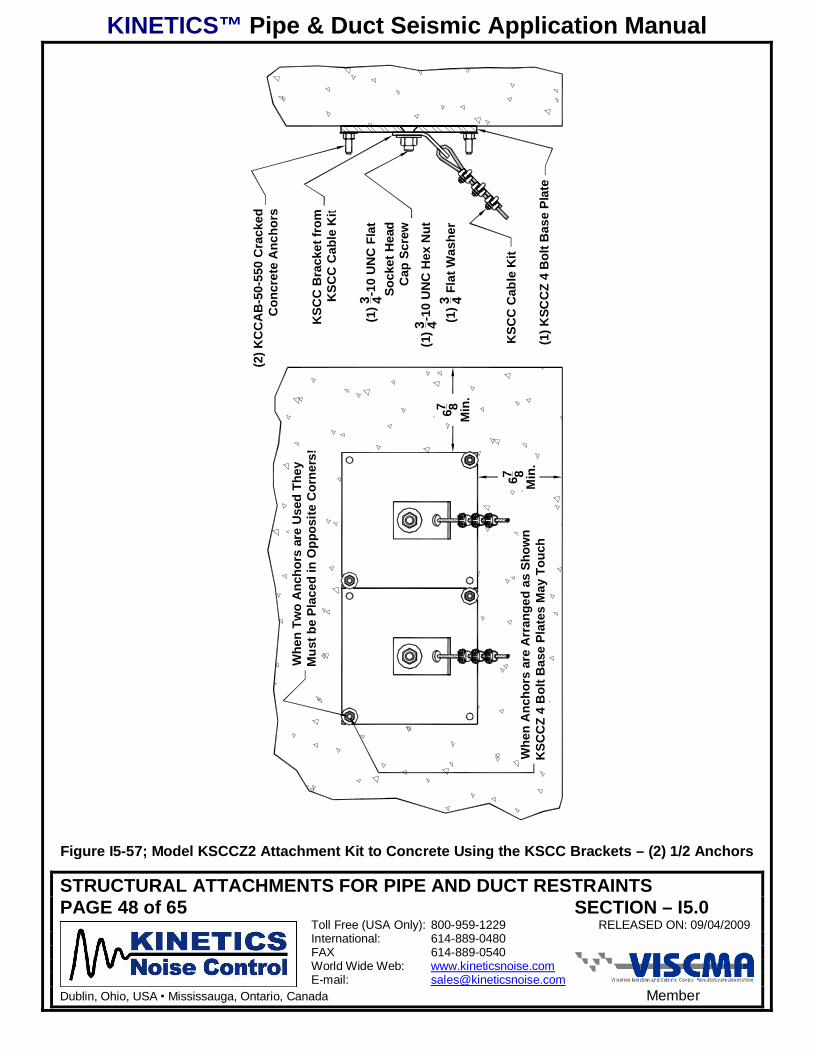
(2) K
CC
AB
-50-
550
Cra
cked
Con
cret
e A
ncho
rs
KSC
C B
rack
et fr
omK
SCC
Cab
le K
it
(1)3 4-1
0 U
NC
Fla
tSo
cket
Hea
dC
ap S
crew
(1)3 4-1
0 U
NC
Hex
Nut
(1)3 4 F
lat W
ashe
r
KSC
C C
able
Kit
(1) K
SCC
Z 4
Bol
t Bas
e Pl
ate
Whe
n Tw
o A
ncho
rs a
re U
sed
They
Mus
t be
Plac
ed in
Opp
osite
Cor
ners
!
Whe
n A
ncho
rs a
re A
rran
ged
as S
how
nK
SCC
Z 4
Bol
t Bas
e Pl
ates
May
Tou
ch
67 8M
in.
67 8M
in.
Figure I5-57; Model KSCCZ2 Attachment Kit to Concrete Using the KSCC Brackets – (2) 1/2 Anchors

KINETICS™ Pipe & Duct Seismic Application Manual
STRUCTURAL ATTACHMENTS FOR PIPE AND DUCT RESTRAINTSPAGE 49 of 65 SECTION – I5.0
Toll Free (USA Only): 800-959-1229 RELEASED ON: 09/04/2009International: 614-889-0480FAX 614-889-0540World Wide Web: www.kineticsnoise.comE-mail: [email protected]
Dublin, Ohio, USA Mississauga, Ontario, Canada Member
(4) K
CC
AB
-50-
550
Cra
cked
Con
cret
e A
ncho
rs
KSC
C B
rack
et fr
omK
SCC
Cab
le K
it
(1)3 4-1
0 U
NC
Fla
tSo
cket
Hea
dC
ap S
crew
(1)3 4-1
0 U
NC
Hex
Nut
(1)3 4 F
lat W
ashe
r
KSC
C C
able
Kit
(1) K
SCC
Z 4
Bol
t Bas
e Pl
ate
67 8M
in.
67 8M
in.
81 2M
inim
umB
etw
een
KSC
CZ4
Bas
ePl
ates
Figure I5-58; Model KSCCZ4 Attachment Kit to Concrete Using the KSCC Brackets – (4) 1/2 Anchors
KINETICS™ Pipe & Duct Seismic Application Manual
STRUCTURAL ATTACHMENTS FOR PIPE AND DUCT RESTRAINTSPAGE 50 of 65 SECTION – I5.0
Toll Free (USA Only): 800-959-1229 RELEASED ON: 09/04/2009International: 614-889-0480FAX 614-889-0540World Wide Web: www.kineticsnoise.comE-mail: [email protected]
Dublin, Ohio, USA Mississauga, Ontario, Canada Member
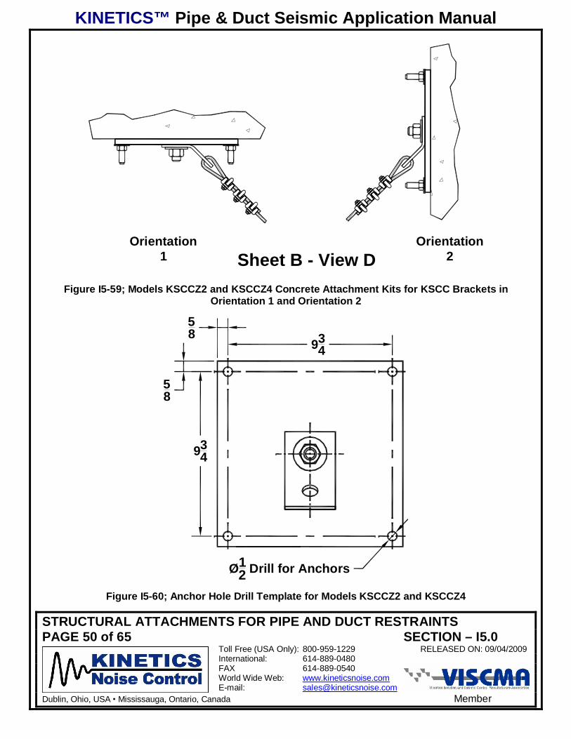
Orientation2
Orientation1 Sheet B - View D
Figure I5-59; Models KSCCZ2 and KSCCZ4 Concrete Attachment Kits for KSCC Brackets inOrientation 1 and Orientation 2
58
58
934
934
Ø12 Drill for Anchors
Figure I5-60; Anchor Hole Drill Template for Models KSCCZ2 and KSCCZ4
KINETICS™ Pipe & Duct Seismic Application Manual
STRUCTURAL ATTACHMENTS FOR PIPE AND DUCT RESTRAINTSPAGE 51 of 65 SECTION – I5.0
Toll Free (USA Only): 800-959-1229 RELEASED ON: 09/04/2009International: 614-889-0480FAX 614-889-0540World Wide Web: www.kineticsnoise.comE-mail: [email protected]
Dublin, Ohio, USA Mississauga, Ontario, Canada Member
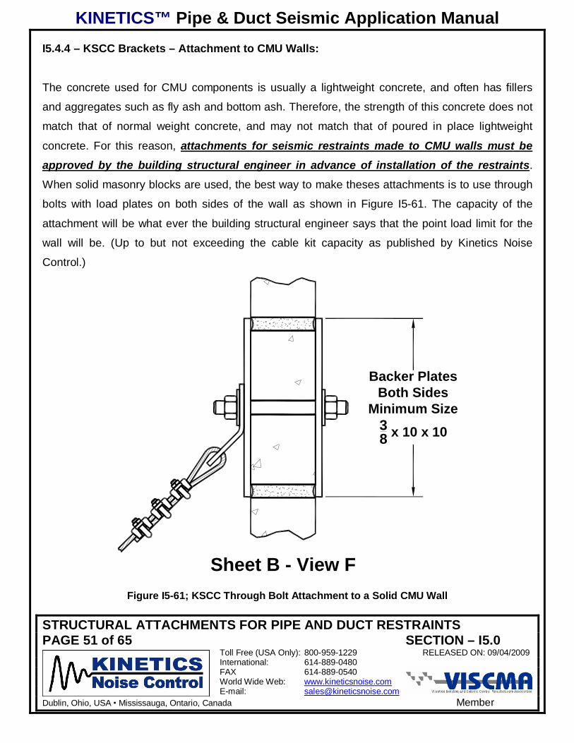
I5.4.4 – KSCC Brackets – Attachment to CMU Walls:
The concrete used for CMU components is usually a lightweight concrete, and often has fillers
and aggregates such as fly ash and bottom ash. Therefore, the strength of this concrete does not
match that of normal weight concrete, and may not match that of poured in place lightweight
concrete. For this reason, attachments for seismic restraints made to CMU walls must be
approved by the building structural engineer in advance of installation of the restraints.
When solid masonry blocks are used, the best way to make theses attachments is to use through
bolts with load plates on both sides of the wall as shown in Figure I5-61. The capacity of the
attachment will be what ever the building structural engineer says that the point load limit for the
wall will be. (Up to but not exceeding the cable kit capacity as published by Kinetics Noise
Control.)
Sheet B - View F
Backer PlatesBoth Sides
Minimum Size38 x 10 x 10
Figure I5-61; KSCC Through Bolt Attachment to a Solid CMU Wall
KINETICS™ Pipe & Duct Seismic Application Manual
STRUCTURAL ATTACHMENTS FOR PIPE AND DUCT RESTRAINTSPAGE 52 of 65 SECTION – I5.0
Toll Free (USA Only): 800-959-1229 RELEASED ON: 09/04/2009International: 614-889-0480FAX 614-889-0540World Wide Web: www.kineticsnoise.comE-mail: [email protected]
Dublin, Ohio, USA Mississauga, Ontario, Canada Member
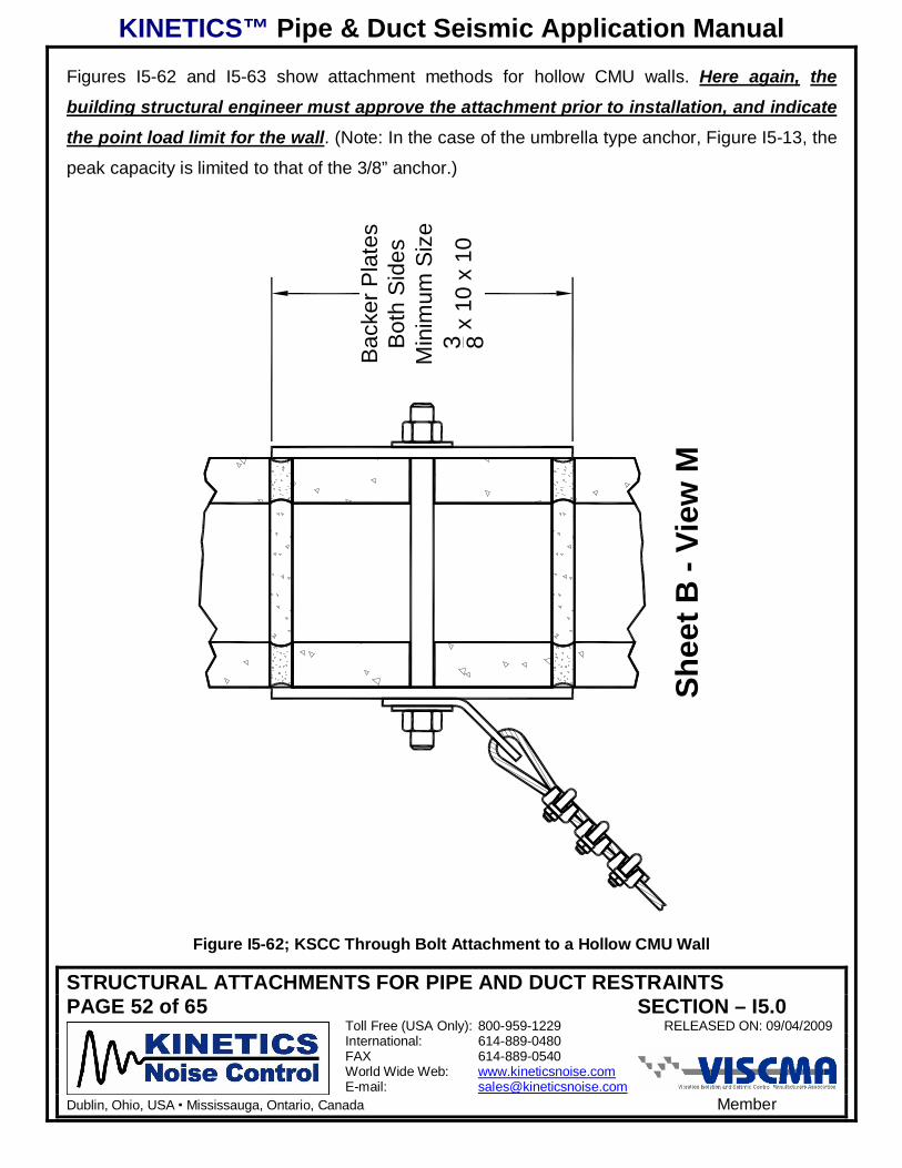
Figures I5-62 and I5-63 show attachment methods for hollow CMU walls. Here again, the
building structural engineer must approve the attachment prior to installation, and indicate
the point load limit for the wall. (Note: In the case of the umbrella type anchor, Figure I5-13, the
peak capacity is limited to that of the 3/8” anchor.)
Shee
t B -
View
M
Bac
ker P
late
sB
oth
Sid
esM
inim
um S
ize
3 8 x 1
0 x
10
Figure I5-62; KSCC Through Bolt Attachment to a Hollow CMU Wall
KINETICS™ Pipe & Duct Seismic Application Manual
STRUCTURAL ATTACHMENTS FOR PIPE AND DUCT RESTRAINTSPAGE 53 of 65 SECTION – I5.0
Toll Free (USA Only): 800-959-1229 RELEASED ON: 09/04/2009International: 614-889-0480FAX 614-889-0540World Wide Web: www.kineticsnoise.comE-mail: [email protected]
Dublin, Ohio, USA Mississauga, Ontario, Canada Member
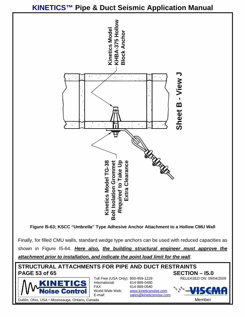
Shee
t B -
View
J
Kin
etic
s M
odel
KH
BA
-375
Hol
low
Blo
ck A
ncho
r
Kin
etic
s M
odel
TG
-38
Bol
t Iso
latio
n G
rom
met
Req
uire
d to
Tak
e U
pEx
tra
Cle
aran
ce
Figure I5-63; KSCC “Umbrella” Type Adhesive Anchor Attachment to a Hollow CMU Wall
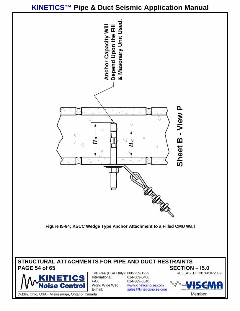
Finally, for filled CMU walls, standard wedge type anchors can be used with reduced capacities as
shown in Figure I5-64. Here also, the building structural engineer must approve theattachment prior to installation, and indicate the point load limit for the wall.
KINETICS™ Pipe & Duct Seismic Application Manual
STRUCTURAL ATTACHMENTS FOR PIPE AND DUCT RESTRAINTSPAGE 54 of 65 SECTION – I5.0
Toll Free (USA Only): 800-959-1229 RELEASED ON: 09/04/2009International: 614-889-0480FAX 614-889-0540World Wide Web: www.kineticsnoise.comE-mail: [email protected]
Dublin, Ohio, USA Mississauga, Ontario, Canada Member
Shee
t B -
View
P
HO
Hef
Anc
hor C
apac
ity W
illD
epen
d U
pon
the
FIll
& M
ason
ary
Uni
t Use
d.
Figure I5-64; KSCC Wedge Type Anchor Attachment to a Filled CMU Wall
KINETICS™ Pipe & Duct Seismic Application Manual
STRUCTURAL ATTACHMENTS FOR PIPE AND DUCT RESTRAINTSPAGE 55 of 65 SECTION – I5.0
Toll Free (USA Only): 800-959-1229 RELEASED ON: 09/04/2009International: 614-889-0480FAX 614-889-0540World Wide Web: www.kineticsnoise.comE-mail: [email protected]
Dublin, Ohio, USA Mississauga, Ontario, Canada Member
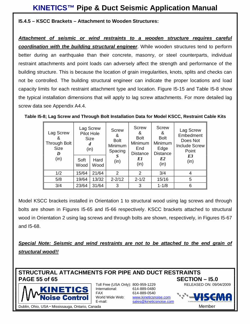
I5.4.5 – KSCC Brackets – Attachment to Wooden Structures:
Attachment of seismic or wind restraints to a wooden structure requires careful
coordination with the building structural engineer. While wooden structures tend to perform
better during an earthquake than their concrete, masonry, or steel counterparts, individual
restraint attachments and point loads can adversely affect the strength and performance of the
building structure. This is because the location of grain irregularities, knots, splits and checks can
not be controlled. The building structural engineer can indicate the proper locations and load
capacity limits for each restraint attachment type and location. Figure I5-15 and Table I5-8 show
the typical installation dimensions that will apply to lag screw attachments. For more detailed lag
screw data see Appendix A4.4.
Table I5-8; Lag Screw and Through Bolt Installation Data for Model KSCC, Restraint Cable Kits
Lag ScrewPilot Hole
Sized
(in)
Lag Screw&
Through BoltSize
D(in) Soft
WoodHardWood
Screw&
BoltMinimumSpacing
S(in)
Screw&
BoltMinimum
EndDistance
E1(in)
Screw&
BoltMinimum
EdgeDistance
E2(in)
Lag ScrewEmbedment
Does NotInclude Screw
PointE3(in)
1/2 15/64 21/64 2 2 3/4 45/8 19/64 13/32 2-2/12 2-1/2 15/16 53/4 23/64 31/64 3 3 1-1/8 6
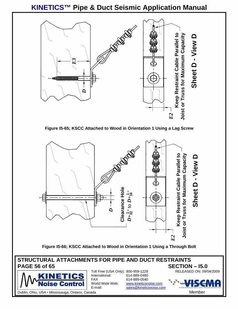
Model KSCC brackets installed in Orientation 1 to structural wood using lag screws and through
bolts are shown in Figures I5-65 and I5-66 respectively. KSCC brackets attached to structural
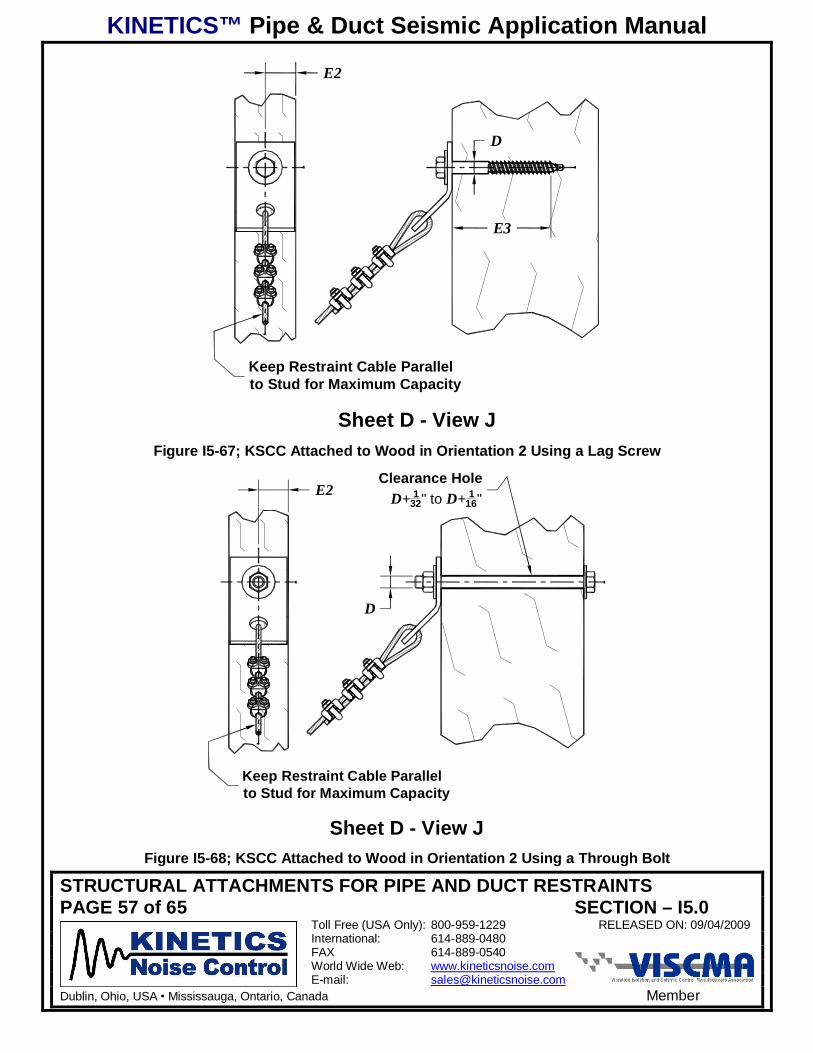
wood in Orientation 2 using lag screws and through bolts are shown, respectively, in Figures I5-67
and I5-68.
Special Note: Seismic and wind restraints are not to be attached to the end grain of
structural wood!!
KINETICS™ Pipe & Duct Seismic Application Manual
STRUCTURAL ATTACHMENTS FOR PIPE AND DUCT RESTRAINTSPAGE 56 of 65 SECTION – I5.0
Toll Free (USA Only): 800-959-1229 RELEASED ON: 09/04/2009International: 614-889-0480FAX 614-889-0540World Wide Web: www.kineticsnoise.comE-mail: [email protected]
Dublin, Ohio, USA Mississauga, Ontario, Canada Member
Kee
p R
estr
aint
Cab
le P
aral
lel t
oJo
ist o
r Tru
ss fo
r Max
imum
Cap
acity
Shee
t D -
View
D
D
E3
E2
Figure I5-65; KSCC Attached to Wood in Orientation 1 Using a Lag Screw
E2
Kee
p R
estr
aint
Cab
le P
aral
lel t
oJo
ist o
r Tru
ss fo
r Max
imum
Cap
acity
Cle
aran
ce H
ole
D+
1 32" t
oD
+1 16
"
D
Shee
t D -
View
D
Figure I5-66; KSCC Attached to Wood in Orientation 1 Using a Through Bolt
KINETICS™ Pipe & Duct Seismic Application Manual
STRUCTURAL ATTACHMENTS FOR PIPE AND DUCT RESTRAINTSPAGE 57 of 65 SECTION – I5.0
Toll Free (USA Only): 800-959-1229 RELEASED ON: 09/04/2009International: 614-889-0480FAX 614-889-0540World Wide Web: www.kineticsnoise.comE-mail: [email protected]
Dublin, Ohio, USA Mississauga, Ontario, Canada Member
Sheet D - View J
D
E3
Keep Restraint Cable Parallelto Stud for Maximum Capacity
E2
Figure I5-67; KSCC Attached to Wood in Orientation 2 Using a Lag Screw
Sheet D - View J
Keep Restraint Cable Parallelto Stud for Maximum Capacity
E2Clearance Hole
D+ 132" to D+ 1
16"
D
Figure I5-68; KSCC Attached to Wood in Orientation 2 Using a Through Bolt
KINETICS™ Pipe & Duct Seismic Application Manual
STRUCTURAL ATTACHMENTS FOR PIPE AND DUCT RESTRAINTSPAGE 58 of 65 SECTION – I5.0
Toll Free (USA Only): 800-959-1229 RELEASED ON: 09/04/2009International: 614-889-0480FAX 614-889-0540World Wide Web: www.kineticsnoise.comE-mail: [email protected]
Dublin, Ohio, USA Mississauga, Ontario, Canada Member
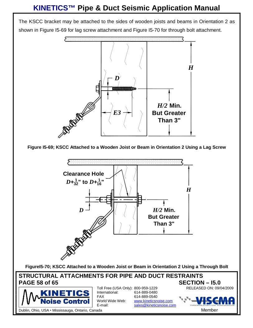
The KSCC bracket may be attached to the sides of wooden joists and beams in Orientation 2 as
shown in Figure I5-69 for lag screw attachment and Figure I5-70 for through bolt attachment.
H/2 Min.But Greater
Than 3"
HD
E3
Figure I5-69; KSCC Attached to a Wooden Joist or Beam in Orientation 2 Using a Lag Screw
H/2 Min.But Greater
Than 3"
H
Clearance HoleD+ 1
32" to D+ 116"
D
FigureI5-70; KSCC Attached to a Wooden Joist or Beam in Orientation 2 Using a Through Bolt
KINETICS™ Pipe & Duct Seismic Application Manual
STRUCTURAL ATTACHMENTS FOR PIPE AND DUCT RESTRAINTSPAGE 59 of 65 SECTION – I5.0
Toll Free (USA Only): 800-959-1229 RELEASED ON: 09/04/2009International: 614-889-0480FAX 614-889-0540World Wide Web: www.kineticsnoise.comE-mail: [email protected]
Dublin, Ohio, USA Mississauga, Ontario, Canada Member
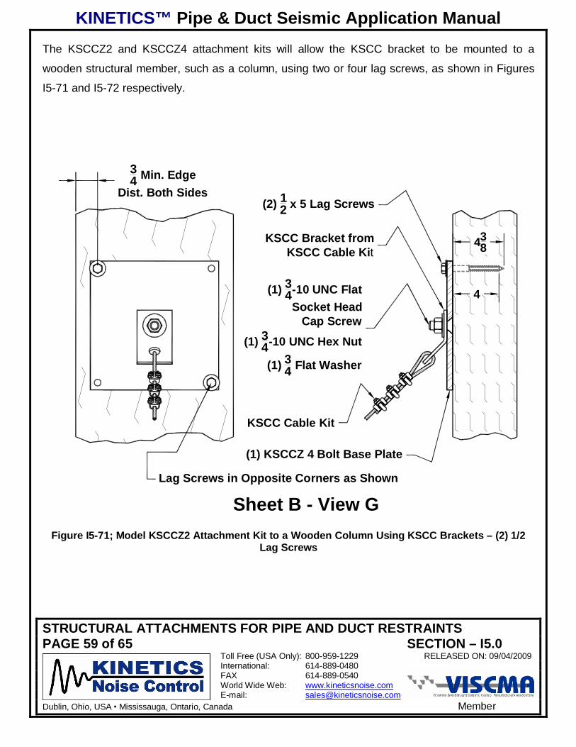
The KSCCZ2 and KSCCZ4 attachment kits will allow the KSCC bracket to be mounted to a
wooden structural member, such as a column, using two or four lag screws, as shown in Figures
I5-71 and I5-72 respectively.
Sheet B - View G
(2) 12 x 5 Lag Screws
KSCC Bracket fromKSCC Cable Kit
(1) 34-10 UNC Flat
Socket HeadCap Screw
(1) 34-10 UNC Hex Nut
(1) 34 Flat Washer
KSCC Cable Kit
(1) KSCCZ 4 Bolt Base Plate
438
4
34 Min. Edge
Dist. Both Sides
Lag Screws in Opposite Corners as Shown
Figure I5-71; Model KSCCZ2 Attachment Kit to a Wooden Column Using KSCC Brackets – (2) 1/2Lag Screws

KINETICS™ Pipe & Duct Seismic Application Manual
STRUCTURAL ATTACHMENTS FOR PIPE AND DUCT RESTRAINTSPAGE 60 of 65 SECTION – I5.0
Toll Free (USA Only): 800-959-1229 RELEASED ON: 09/04/2009International: 614-889-0480FAX 614-889-0540World Wide Web: www.kineticsnoise.comE-mail: [email protected]
Dublin, Ohio, USA Mississauga, Ontario, Canada Member
Sheet B - View G
(4) 12 x 5 Lag Screws
KSCC Bracket fromKSCC Cable Kit
(1) 34-10 UNC Flat
Socket HeadCap Screw
(1) 34-10 UNC Hex Nut
(1) 34 Flat Washer
KSCC Cable Kit
(1) KSCCZ 4 Bolt Base Plate
438
4
34 Min. Edge
Dist. Both Sides
FigureI5-72; Model KSCCZ4 Attachment Kit to a Wooden Column Using KSCC Brackets – (4) 1/2Lag Screws
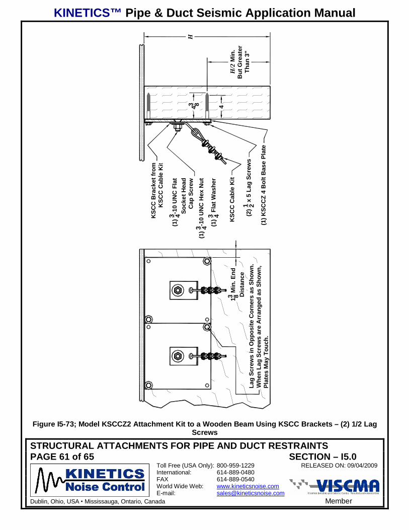
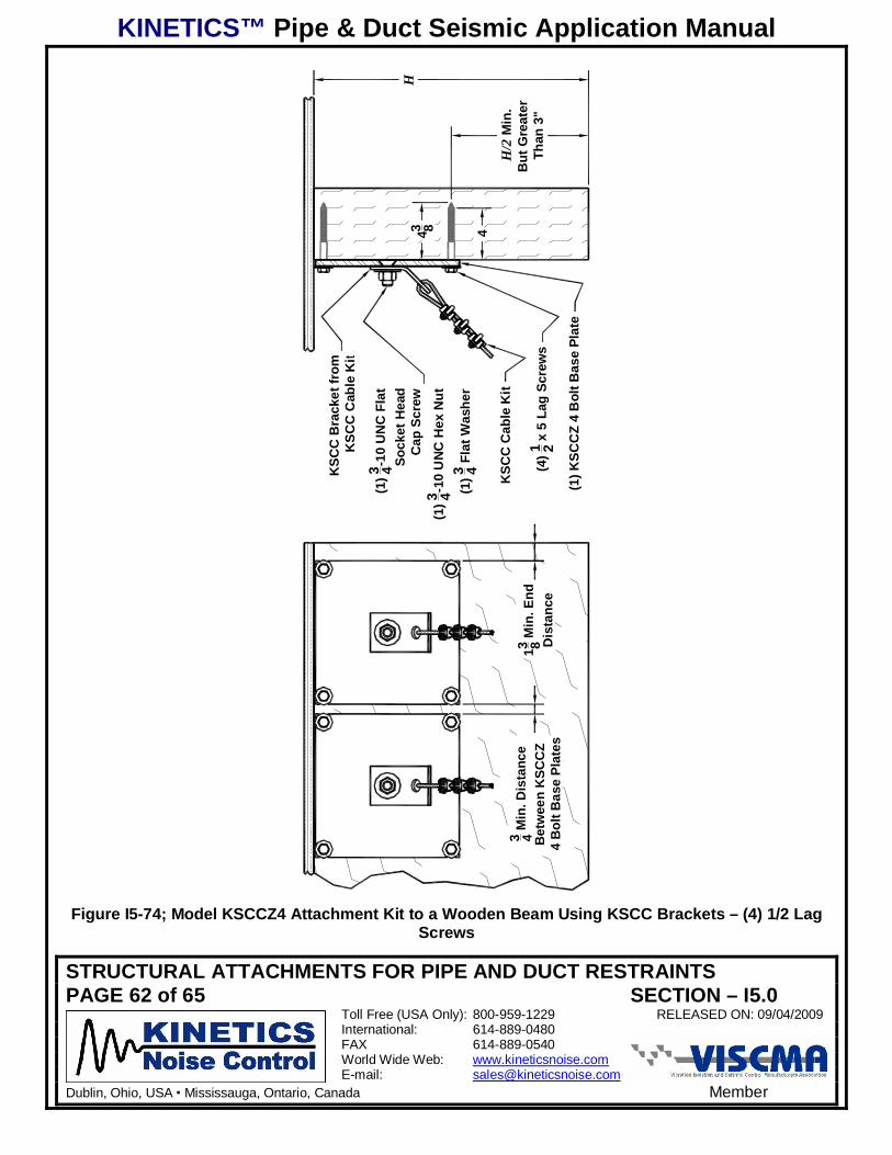
The KSCCZ2 and KSCCZ4 attachment kits will also allow the KSCC bracket to be mounted to a
wooden structural beam using two or four lag screws. Figures I5-73 and I5-74 show the KSCCZ2
and KSCCZ4, respectively, mounted to a wooden beam. Figure I5-60 provides the dimensional
information to layout the drill pattern for the pilot holes. The pilot drill size is given in Table I5-6 for
both hard and soft woods.
KINETICS™ Pipe & Duct Seismic Application Manual
STRUCTURAL ATTACHMENTS FOR PIPE AND DUCT RESTRAINTSPAGE 61 of 65 SECTION – I5.0
Toll Free (USA Only): 800-959-1229 RELEASED ON: 09/04/2009International: 614-889-0480FAX 614-889-0540World Wide Web: www.kineticsnoise.comE-mail: [email protected]
Dublin, Ohio, USA Mississauga, Ontario, Canada Member
KSC
C B
rack
et fr
omK
SCC
Cab
le K
it
(1)3 4-1
0 U
NC
Fla
tSo
cket
Hea
dC
ap S
crew
(1)3 4-1
0 U
NC
Hex
Nut
(1)3 4 F
lat W
ashe
r
(1) K
SCC
Z 4
Bol
t Bas
e Pl
ate
(2)1 2 x
5 L
ag S
crew
s
KSC
C C
able
Kit
H
13 8 Min
. End
Dis
tanc
eLa
g Sc
rew
s in
Opp
osite
Cor
ners
as
Show
n.W
hen
Lag
Scre
ws
are
Arr
ange
d as
Sho
wn,
Plat
es M
ay T
ouch
.
H/2
Min
.B
ut G
reat
erTh
an 3
"
43 8 4
Figure I5-73; Model KSCCZ2 Attachment Kit to a Wooden Beam Using KSCC Brackets – (2) 1/2 LagScrews
KINETICS™ Pipe & Duct Seismic Application Manual
STRUCTURAL ATTACHMENTS FOR PIPE AND DUCT RESTRAINTSPAGE 62 of 65 SECTION – I5.0
Toll Free (USA Only): 800-959-1229 RELEASED ON: 09/04/2009International: 614-889-0480FAX 614-889-0540World Wide Web: www.kineticsnoise.comE-mail: [email protected]
Dublin, Ohio, USA Mississauga, Ontario, Canada Member
KSC
C B
rack
et fr
omK
SCC
Cab
le K
it
(1)3 4-1
0 U
NC
Fla
tSo
cket
Hea
dC
ap S
crew
(1)3 4-1
0 U
NC
Hex
Nut
(1)3 4 F
lat W
ashe
r
(1) K
SCC
Z 4
Bol
t Bas
e Pl
ate
(4)1 2 x
5 L
ag S
crew
s
KSC
C C
able
Kit
13 8 Min
. End
Dis
tanc
e
H/2
Min
.B
ut G
reat
erTh
an 3
"
H43 8 4
3 4 Min
. Dis
tanc
eB
etw
een
KSC
CZ
4 B
olt B
ase
Plat
es
Figure I5-74; Model KSCCZ4 Attachment Kit to a Wooden Beam Using KSCC Brackets – (4) 1/2 LagScrews
KINETICS™ Pipe & Duct Seismic Application Manual
STRUCTURAL ATTACHMENTS FOR PIPE AND DUCT RESTRAINTSPAGE 63 of 65 SECTION – I5.0
Toll Free (USA Only): 800-959-1229 RELEASED ON: 09/04/2009International: 614-889-0480FAX 614-889-0540World Wide Web: www.kineticsnoise.comE-mail: [email protected]
Dublin, Ohio, USA Mississauga, Ontario, Canada Member
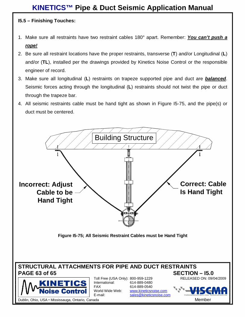
I5.5 – Finishing Touches:
1. Make sure all restraints have two restraint cables 180° apart. Remember: You can’t push a
rope!2. Be sure all restraint locations have the proper restraints, transverse (T) and/or Longitudinal (L)
and/or (TL), installed per the drawings provided by Kinetics Noise Control or the responsible
engineer of record.
3. Make sure all longitudinal (L) restraints on trapeze supported pipe and duct are balanced.
Seismic forces acting through the longitudinal (L) restraints should not twist the pipe or duct
through the trapeze bar.
4. All seismic restraints cable must be hand tight as shown in Figure I5-75, and the pipe(s) or
duct must be centered.
Building Structure
Correct: CableIs Hand Tight
Incorrect: AdjustCable to beHand Tight
Figure I5-75; All Seismic Restraint Cables must be Hand Tight
KINETICS™ Pipe & Duct Seismic Application Manual
STRUCTURAL ATTACHMENTS FOR PIPE AND DUCT RESTRAINTSPAGE 64 of 65 SECTION – I5.0
Toll Free (USA Only): 800-959-1229 RELEASED ON: 09/04/2009International: 614-889-0480FAX 614-889-0540World Wide Web: www.kineticsnoise.comE-mail: [email protected]
Dublin, Ohio, USA Mississauga, Ontario, Canada Member
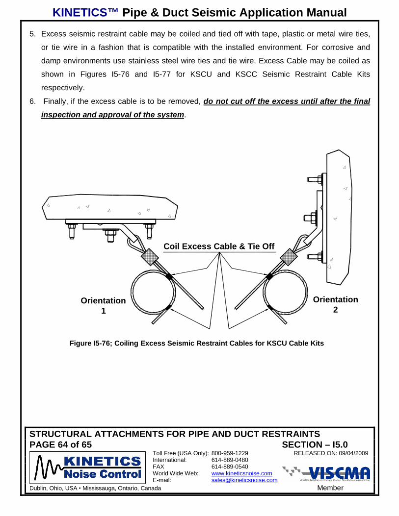
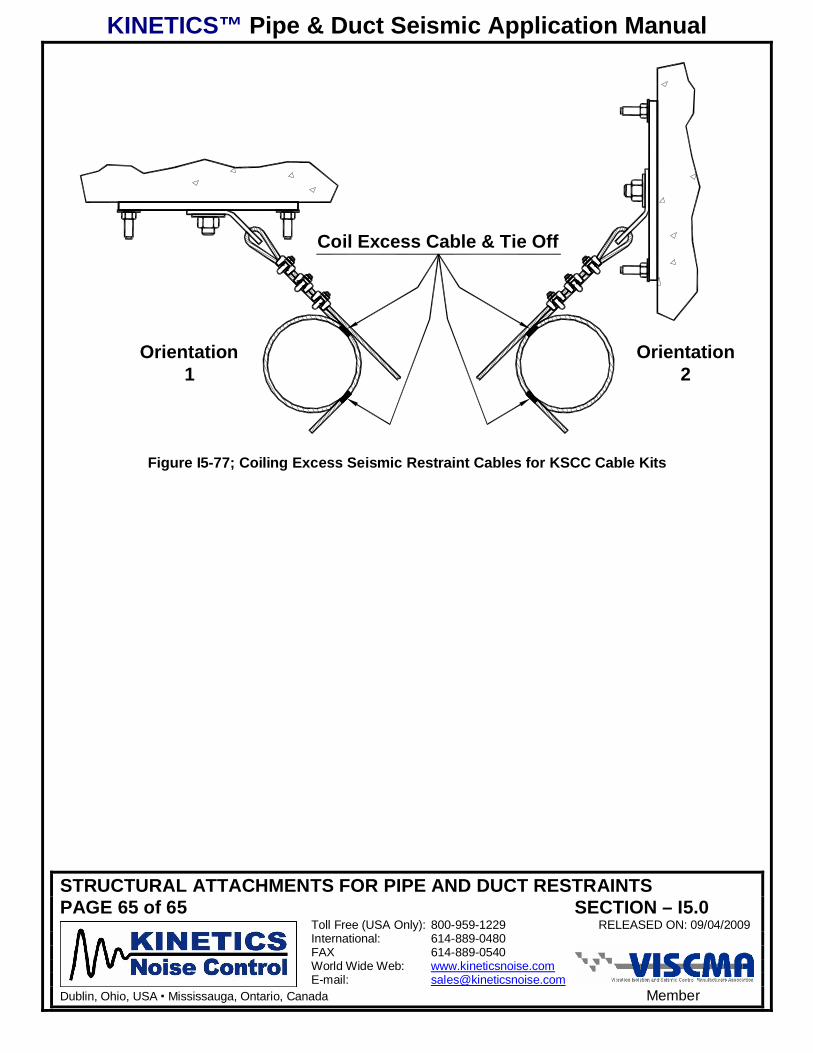
5. Excess seismic restraint cable may be coiled and tied off with tape, plastic or metal wire ties,
or tie wire in a fashion that is compatible with the installed environment. For corrosive and
damp environments use stainless steel wire ties and tie wire. Excess Cable may be coiled as
shown in Figures I5-76 and I5-77 for KSCU and KSCC Seismic Restraint Cable Kits
respectively.
6. Finally, if the excess cable is to be removed, do not cut off the excess until after the final
inspection and approval of the system.
Orientation2
Orientation1
Coil Excess Cable & Tie Off
Figure I5-76; Coiling Excess Seismic Restraint Cables for KSCU Cable Kits
KINETICS™ Pipe & Duct Seismic Application Manual
STRUCTURAL ATTACHMENTS FOR PIPE AND DUCT RESTRAINTSPAGE 65 of 65 SECTION – I5.0
Toll Free (USA Only): 800-959-1229 RELEASED ON: 09/04/2009International: 614-889-0480FAX 614-889-0540World Wide Web: www.kineticsnoise.comE-mail: [email protected]
Dublin, Ohio, USA Mississauga, Ontario, Canada Member
Orientation2
Orientation1
Coil Excess Cable & Tie Off
Figure I5-77; Coiling Excess Seismic Restraint Cables for KSCC Cable Kits