securing loads using positive locking with faktor 4
TRANSCRIPT
118
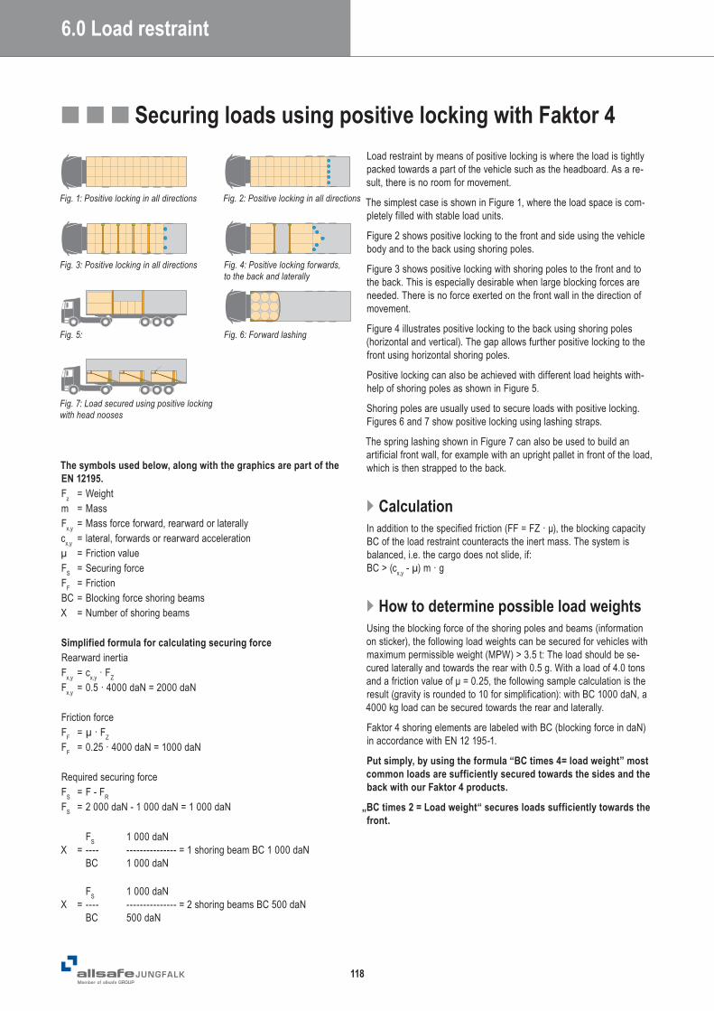
■■■ Securing loads using positive locking with Faktor 4Load restraint by means of positive locking is where the load is tightly packed towards a part of the vehicle such as the headboard. As a re-sult, there is no room for movement.
The simplest case is shown in Figure 1, where the load space is com-pletely filled with stable load units.
Figure 2 shows positive locking to the front and side using the vehicle body and to the back using shoring poles.
Figure 3 shows positive locking with shoring poles to the front and to the back. This is especially desirable when large blocking forces are needed. There is no force exerted on the front wall in the direction of movement.
Figure 4 illustrates positive locking to the back using shoring poles (horizontal and vertical). The gap allows further positive locking to the front using horizontal shoring poles.
Positive locking can also be achieved with different load heights with-help of shoring poles as shown in Figure 5.
Shoring poles are usually used to secure loads with positive locking.Figures 6 and 7 show positive locking using lashing straps.
The spring lashing shown in Figure 7 can also be used to build an artificial front wall, for example with an upright pallet in front of the load, which is then strapped to the back.
} CalculationIn addition to the specified friction (FF = FZ · μ), the blocking capacity BC of the load restraint counteracts the inert mass. The system is balanced, i.e. the cargo does not slide, if: BC > (cx,y - µ) m · g
} How to determine possible load weightsUsing the blocking force of the shoring poles and beams (information on sticker), the following load weights can be secured for vehicles with maximum permissible weight (MPW) > 3.5 t: The load should be se-cured laterally and towards the rear with 0.5 g. With a load of 4.0 tons and a friction value of μ = 0.25, the following sample calculation is the result (gravity is rounded to 10 for simplification): with BC 1000 daN, a 4000 kg load can be secured towards the rear and laterally.
Faktor 4 shoring elements are labeled with BC (blocking force in daN) in accordance with EN 12 195-1.
Put simply, by using the formula “BC times 4= load weight” most common loads are sufficiently secured towards the sides and the back with our Faktor 4 products.
„BC times 2 = Load weight“ secures loads sufficiently towards the front.
The symbols used below, along with the graphics are part of the EN 12195.Fz = Weightm = MassFx,y = Mass force forward, rearward or laterallycx,y = lateral, forwards or rearward accelerationµ = Friction valueFS = Securing forceFF = FrictionBC = Blocking force shoring beamsX = Number of shoring beams
Simplified formula for calculating securing forceRearward inertiaFx,y = cx,y · FZ Fx,y = 0.5 · 4000 daN = 2000 daN Friction forceFF = µ · FZ
FF = 0.25 · 4000 daN = 1000 daN
Required securing forceFS = F - FR
FS = 2 000 daN - 1 000 daN = 1 000 daN
FS 1 000 daNX = ---- --------------- = 1 shoring beam BC 1 000 daN BC 1 000 daN
FS 1 000 daNX = ---- --------------- = 2 shoring beams BC 500 daN BC 500 daN
6.0 Load restraint
Fig. 1: Positive locking in all directions Fig. 2: Positive locking in all directions
Fig. 3: Positive locking in all directions Fig. 4: Positive locking forwards, to the back and laterally
Fig. 6: Forward lashingFig. 5:
Fig. 7: Load secured using positive locking with head nooses
Head noose

119
LOAD
RES
TRAI
NT
} KAT for horizontal restraintKAT Combi beams are locked into the Combi tracks by releasing the locking device, found at each end of the beam. To release the beam,
simply unlock the locking device-on one side. By lowering the beam on one side the opposite side unlocks and the beam can be easily removed.
KAT is also available for keyhole tracks.
KAT Combi with its BC 800 daN x 4 is able to restrain 3200 kg towards the back.
} AJS System for securing loads in curtainsidersLoads that are difficult to secure, such as bulky packages, Big Bags, octabins etc,. can be safely secured by means of positive locking with the AJS system.
AJS lashing profiles are mounted laterally between the pillars. The load is then secured laterally with KAT AJS beams.
This system is great for loading and unloading partial loads.
KAT AJS with its BC 2000 daN x 4 is able to restrain 8000 kg towards the back.
} PAT the high-strength beam for curtainsiders
PAT can be attached to longitu-nal laths, and drop boards. By applying slight pressure, PAT’s closures tilt into the laths and create positive locking.
PAT 1000 with its BC 1000 daN x 4 is able to restrain 4000 kg towards the back.
} Load restraint for LCVFor better control over the vehicle and to comply with weight distri-bution regulations, cargo should be loaded towards the back and in the middle of the floor surface.
Our solution is placing the load between four specially designed KIM 5 x 7 airline beams which restrain the load from the front and the back. The beams are placed as close to the goods as possible. The beams are fitted vertically into roof and floor tracks which creates positive locking.
Depending on the load, KIM 44 elements are inserted between the shoring beams. Lateral restraint is provided by lashing straps, which can be connected to the Airline track on the KIM 5 x 7 beam.
The patented load securing system is tested and certified in compliance with VDI 2700 for vehicles up to 3.5t MPW.
} KIM for horizontal and vertical useKIM is used horizontally in box vans in the sidewall tracks. Vertically, KIM can be used in box or curtainsider vehicles. For this purpose, KIM is fitted into the floor track next to the load. With help of the pull strap, the spring-loaded end is then fitted into the roof track. The spring-loa-ded end should always be placed in the roof track whereas it could spring out of the floor tracks.
KIM 44 Pro is the only shoring pole that can be used vertically and horizontally in a transporter.
KIM 55 with a BC of 500 daN x 4 gives you 2000 kg rear or lateral load restraint
■■■ Practical examples of positive locking