sector guidance note ippc sg4 - scottish environment ... · galvanising sector guidance note ippc...
TRANSCRIPT

www.defra.gov.uk
Sector Guidance Note IPPC SG 5 Integrated Pollution Prevention and Control (IPPC) Secretary of State’s Guidance for A2 Activities in the Galvanising Sector
September 2006

Sector Guidance Note IPPC SG5 September 2006
Integrated Pollution Prevention and Control (IPPC)
Secretary of State's Guidance for A2 Activities in the
Galvanising Sector


Contents 1 Introduction ...................................................................................... 1
Background ……………………………………………………………………………………………. 1 Best Available Techniques (BAT) ..............................................................……….…………….. 1 Installations covered ...........................................…………………………………………………… 2 Review and upgrading periods ......................................................................…......…………… 3 Existing installations or activities ................................................................……....……………… 3 New installations or activities ................................................................……….....……………… 4 Substantially changed installations or activities ......................................………....…………….. 4 Permit reviews ............................................................................................……………………. 4 Summary of releases ..............................................................................................…………… 5
2 Emission limits and other provisions ............................................ 6 Contained emissions to air associated with the use of BAT ......……………………………….. 6 Benchmark emissions to water associated with the use of BAT ................……………………. 7
3 Techniques for pollution control .................................................. 8 Installation description and in-process controls .........................…………................................ 8
Summary of activities 8 Delivery, storage and handling of raw materials………………………………………. 8 Pre-treatment …………………………………………………………………………….. 10 Degreasing ………………………………………………………………………………. 10 Pickling …………………………………………………………………………………… 11 Stripping …………………………………………………………………………………. 12 Rinsing ……………………………………………………………………………………. 12 Fluxing …………………………………………………………………………………….. 13 Galvanizing ………………………………………………………………………………. 15 Post treatment …………………………………………………………………………… 17
Emissions control .......................................................................................……………............. 19 Point source emissions to air ..................................................………...................... 19 Point source emissions to surface water and sewer ...................……….................. 21 Point source emissions to groundwater .......................……….................................. 22 Fugitive emissions to air ....................................................………............................ 23 Fugitive emissions to surface water, sewer and groundwater .………..................... 23 Odour ....................................................................................………........................ 25
Management .........................................................................................…………..................... 25 Raw materials .........................................................................................…………................... 27
Raw materials selection ........................................................………........................ 27 Waste minimisation (optimising the use of raw materials) ......………...................... 29 Water use ............................................................................……….......................... 30
Waste handling .....................................................................................…………..................... 31 Waste re-use, recovery, recycling and disposal ......................................…………................... 32 Energy .................................................................................................…………....................... 33
Basic energy efficiency requirements ..................................………......................... 33 Additional energy efficiency requirements .............................………....................... 33
Accidents ................................................................................................…………................... 34 Noise and Vibration ................................................................................…………................... 36 Monitoring ..................................................................................................…………................ 36
Monitoring emissions to air ..............................................………............................. 38 Monitoring emissions to water .......................................………................................ 38 Environmental monitoring (beyond installation boundary).........………..................... 38 Monitoring of process variables ...............................................………..................... 38
Information Provisions…………………………………………………………………….………….. 40 References ..............................................................................................………...................... 44 Abbreviations ...........................................................................................………..........…......... 45
Appendix 1: Summary of changes....................................………………………………….... 46 Appendix 2: Some common monitoring methods for releases to water ........................ 48 Appendix 3: Pickling optimisation curve 49
Galvanising Sector Guidance Note IPPC SG5 (2006) | Issue 2.0 | published September 2006 i

List of Tables
Table 1 Compliance timetable…….................................................................................. 3 Table 2 Summary of direct releases ............................................................................... 5 Table 3 Contained emissions to air associated with the use of BAT .............................. 6 Table 4 Emissions to water associated with the use of BAT .......................................... 7 Table 5 Selection of raw materials ................................................................................. 28 Table 6 Solid waste stream: routes currently taken ........................................................ 32 Table 7a Summary of provisions for reporting and notification ………………………….. 40 Table 7b Summary of provisions for additional information……………………………….. 42 Table 8 Summary of changes…….…………………………………………………..……… 46 Table 9: Measurement methods for common substances to water ……………………… 48
List of figures
Figure A3.1 Kleingarn pickling system …………………………………………………………. 49
Galvanising Sector Guidance Note IPPC SG5 (2006) | Issue 2.0 | published September 2006 ii

1 Introduction Background 1.1 This sector guidance note is issued by the Secretary of State and the Welsh Assembly Government
(WAG), following consultation with relevant trade bodies, representatives of regulators including members of the Industrial Pollution Liaison Committee, and other interested organisations.
1.2 The note constitutes statutory guidance under regulation 37 of the Pollution Prevention and Control
(England and Wales) Regulations 2000, SI 1973 (Ref 1) on the integrated pollution prevention and control standards appropriate for the generality of new and existing A2 installations in the galvanising sector.
These installations require a permit to operate in accordance with the 2000 Regulations under what is known as the Local Authority-Integrated Pollution Prevention and Control (LA-IPPC) regime. Local authority regulators are required by Regulation 37 to have regard to this guidance. The Secretary of State / WAG will also treat this guidance as one of the material considerations when determining any appeals made under the Regulations against a local enforcing authority decision.
1.3 The guidance also (where appropriate) gives details of any mandatory requirements affecting
emissions and impacts from these installations, which are in force at the time of publication. These include requirements contained in directions from the Secretary of State / WAG.
1.4 This is one of a series of such guidance notes aimed at providing a strong framework for consistent
and transparent regulation of LA-IPPC installations. 1.5 General guidance explaining LA-IPPC and setting out the policy and procedures, is contained in the
“General Guidance Manual on Policy and Procedures for A2 and B Installations” (Ref 2) available from www.defra.gov.uk/environment/ppc/index.htm, to be referred to in this document as the "General Guidance Manual.” This is designed for operators and members of the public, as well as for local authority regulators.
Best Available Techniques (BAT) 1.6 BAT is the main basis for determining standards in LA-IPPC. This sector guidance note addresses
what is considered by the Secretary of State/WAG to constitute BAT for general galvanizing plant.
This sector guidance note takes into account information contained in the BREF (Ref 3)
As made clear in Chapter 12 of the General Guidance Manual, BAT for each installation should be assessed by reference to the appropriate sector guidance note, and these notes should be regarded by local authorities as their primary reference document for determining BAT in drawing up permits. In general terms what is BAT for one installation is likely to be BAT for a comparable installation. However, determination of what is BAT is ultimately a matter for case-by-case decision taking into account that individual circumstances may affect BAT judgements and what are the appropriate permit conditions.
Thus, for each galvanising installation, local authorities (subject to appeal to the Secretary of State / WAG) should regard this guidance note as a baseline, but ensure they take into account any relevant case-specific factors such as the individual process configuration and other characteristics, its size, location, and any other relevant features of the particular installation. Further guidance on this, including the issue of taking account of operators' individual financial position, is contained in chapter 12 of the General Guidance Manual.
1.7 If there are any applicable mandatory EU emission limits, these must be met, although BAT may go further. The same applies to UK regulations, except that, in reconciling BAT with the Control of Pollution (Oil Storage) (England) Regulations 2001, SI 2954, it may be acceptable to achieve an
Galvanising Sector Guidance Note IPPC SG5 (2006) | Issue 2.0 | published September 2006 1

equivalent level of control to that specified in the 2001 regulations (although the oil storage regulations do not apply in Wales, they should be regarded as an indication of BAT in Wales)1.
Who is this guidance for? 1.8 This guidance is for:
local authority regulators: who must have regard to the guidance when determining applications and when regulating installations which have a permit operators: who are best advised also to have regard to it when making applications and in the subsequent operation of their activities members of the public: who may be interested to know what standards are envisaged for the generality of installations in this sector.
1.9 The guidance is based on the state of knowledge and understanding of installations in this sector,
their potential impact on the environment, and the available control techniques at the time of writing. The guidance may be amended from time to time in order to keep abreast with developments, including improvements or changes in techniques and new understanding of environmental impacts and risks. Any such amendments may be issued in a complete revision of this note, or in separate additional guidance notes which address specific issues. (N.B. It may not always be possible to issue amending guidance quickly enough to keep in absolute step with rapid changes, which might be another justification in particular cases for diverging from this note.) Steps will be taken to ensure that those who need to know about changes are informed of any amendments. Operators (and their advisers) are, however, strongly advised to check with the relevant local authority whether there have been any amendments before relying on this note for the purposes of applying for a permit or making any other decisions where BAT and related matters may be a consideration.
Terminology 1.10 In addition to the General Guidance Manual referred to above, explanation or clarification of certain
terms used in this sector guidance note may be found in a general guidance note issue under Part I of the Environmental Protection Act 1990: ‘Interpretation of terms used in process guidance notes’, known as General Guidance Note 4 - GG4 - published by HMSO in 1991. Where there is any conflict between GG4 and the guidance issued in this note or in the General Guidance Manual, the latter two documents should prevail, as should any subsequent guidance issued in relation to LA-IPPC.
Installations covered 1.11 This note covers installations, described in Section 2.1 Part A2 of Schedule 1 to the PPC Regulations
(as amended) (Ref 1), Section 2.2 Part A2 or Section 2.3 Part A2 as follows: • Section 2.1 - Ferrous Metals, Part A2
(c) Applying protective fused metal coatings with an input of more than 2 tonnes of crude steel per hour.
• Section 2.2 - Non Ferrous Metals, Part A2 (a) Melting, including making alloys, of non-ferrous metals, including recovered products (refining, foundry casting, etc.) where -
i. the plant has a melting capacity of more than 4 tonnes a day for lead or cadmium or 20 tonnes per day for all other metals; and
ii. no furnace(other than a vacuum furnace), bath or other holding vessel used in the plant for the melting has a design holding capacity of 5 tonnes or more
• Section 2.3 - Surface Treating Metals and Plastic Materials, Part A2
(a) Surface treating metals and plastic materials using an electrolytic or chemical process where the aggregated volume of the treatment vats is more than 30m3 and where the activity is carried out at the same installation as one or more activities falling within -
i. Part A2 or B of Section 2.1 (Ferrous Metals); ii. Part A2 or B of Section 2.2 (Non Ferrous Metals); or iii. Part A2 or B of Section 6.4 (Coating Activities, Printing and Textile Treatments);
1 Further guidance on the Oil Storage Regulations, if needed, is available from www.environment-agency.gov.uk/osr
Galvanising Sector Guidance Note IPPC SG5 (2006) | Issue 2.0 | published September 2006 2

The installation includes the main activities as stated above and associated activities which have a technical connection with the main activities and which may have an effect on emissions and pollution.
Review and Upgrading Periods Existing installations or activities 1.13
1.14
1.15
1.16
Earlier guidance, PG2/2 (96), relating to emissions to air advised that upgrading to that standard should usually have been completed by 1 October 1996, depending upon the history of the activity. Requirements still outstanding from any existing upgrading programme should be completed.
The previous version of this guidance, SG5 2003, contained improvements that were required to be completed up to 1 April 2005. These include paragraphs 3.75, 3.92, 3.102, 3.106, BAT 9, 26, 42, 47, 58, 59, 62, 73, 81, 83 and Table 3 as presented in SG5 2003. Installations should be upgraded to these standards by the date of publication of this note.
The new provisions of this note and the dates by which compliance with these provisions is expected, are listed in Table 1 below, together with the paragraph number where the relevant guidance is to be found. Compliance with the new provisions should normally be achieved by the dates shown. Permits should be drafted having regard to this compliance timetable. (1) Where this guidance note specifies provisions which are additional to, higher than or different to
those in PG note 2/2(96) and SG5 2003, only in exceptional circumstances should upgrading of existing installations and activities having regard to these additional/higher/different provisions be completed later than the compliance date specified in Table 1 below.
(2) Where standards or provisions in PG note 2/2(96) and SG5 2003 have been deleted in this guidance note or where this guidance note specifies less stringent provisions than those in PG note 2/2(96) and SG5 2003, the new LAIPPC permit should reflect this straightaway.
Consideration is currently being given to how surface water runoff from roofs and yards should be dealt with and proposals will be reviewed in October 2006. The benchmark emission to water in Section 2, including the zinc and ammonia limits, may be revised in the light of that review
Table 1: Compliance requirements
Guidance
Reference
Compliance Date
Zinc and ammonia in runoff from roofs and yards discharged to surface water: Prevent contamination or treat
BAT36
Industry proposals will be reviewed in October 2006.
Groundwater Contamination Risk Audit and protection systems
3.88 – 3.95 & BAT 42 - 49
1 April 2007
Odour Assessments, and if needed an odour management plan
3.102 & BAT 50 and 51
1 July 2006
Environmental Management Systems 3.107- 3.112 & BAT 52 1 April 2007 Formal Structure for Environmental Control & Training
BAT 58 & BAT 59 1 April 2007
Benchmarking Water Usage BAT 68 1 April 2007 Recycling Markets 3.140 & BAT 81 1 April 2007 Accident Prevention Measures BAT 91 to BAT 94 1 April 2007 QA/QC of Monitoring Systems BAT 103 1 April 2007 Annual Waste Reporting BAT 115 1 April 2007 All Other Requirements To be complied with as soon as
practicable, which in most cases should be within 12 months of the publication of this note
Galvanising Sector Guidance Note IPPC SG5 (2006) | Issue 2.0 | published September 2006 3
1.17
1.18
1.19
1.20
Replacement plant should normally be designed to meet the appropriate standards specified for new installations or activities.
New installations or activities
For new installations or activities - from the first day of operation the permit should have regard to the full standards of this guidance.
Substantially changed installations or activities
For substantially changed installations or activities - as from the first day of operation, the permit should normally have regard to the full standards of this guidance with respect to the parts of the installation that have been substantially changed and any part of the installation affected by the change.
Permit Reviews
Permits should be reviewed in accordance with the guidance in chapter 26 of the General Guidance Manual. The review frequencies given in that chapter are considered appropriate for activities and installations covered by this sector guidance note.
Galvanising Sector Guidance Note IPPC SG5 (2006) | Issue 2.0 | published September 2006 4

Summary of Releases
Table 2: Summary of direct releases
Source Releases
Mat
eria
l sto
rage
and
ha
ndlin
g, G
ener
al
oper
atio
ns a
nd m
aint
enan
ce
Shot
blas
ting
Deg
reas
ing
Pick
ling
Rin
sing
Strip
ping
Flux
ing
Hot
dip
ping
Post
trea
tmen
t
Oxides of nitrogen A
Oxides of carbon A
Hydrochloric acid W L L W A A
Sulphuric acid W L A W A W
Hydrogen chloride A A
Zinc chloride W A
Ammonium chloride W A
Iron oxide A
Metallic iron particulates A
Phosphoric acid W L
Sodium hydroxide W W
Zinc oxides A
Lead oxides (from wire galvanizing) A
Chromates W W L
Liquid fuel oils and greases
L W L
Ash A L
Sludge waste L L L
Refractory waste L
KEY
A – Release to Air, W – Release to Water, L – Release to Land
Substances include their compounds, except where separate reference to the compound is made. Releases to air may also be released to land or water, depending upon the abatement technology employed, e.g. via collected dusts, sludges or liquors.
N.B. It should be noted that this is not necessarily an exhaustive list. Equally not all installations will necessarily have all these releases. This table does not list indirect releases for example zinc and ammonium chloride fume deposited on roofs and yards and then carried by runoff into surface water.
Galvanising Sector Guidance Note IPPC SG5 (2006) | Issue 2.0 | published September 2006 5

2 Emission limits and other provisions 2.1 This section contains emission limits, mass release rates and other requirements that are judged
for the generality of the activities within the sector to represent BAT.
Contained emissions to air associated with the use of BAT 2.2 Concentration limits are only applicable to contained emissions exhausted to external atmosphere.
Table 3: Contained emissions to air associated with the use of BAT
Particulate matter Source
Emission limit Type of monitoring Frequency of monitoring (subject to 3.162 - 3.166)
1 All galvanizing baths.
15 mg/m3
Manual extractive test to comply with BS ISO 12141: 2002 or BS EN 13284:Part 1
At least once a year and quarterly for low fuming flux operations where continuous indicative monitoring is not being used.
2 Galvanizing baths not using low fuming flux but using abatement plant.
15 mg/m3
Indicative monitoring.
Continuous
3 All authorised emission points from low fuming flux operations without abatement prior to discharge.
No persistent visible emission.
Operator observations.
At least daily.
4 Stack or duct emissions from contained sources other than galvanizing e.g. shot blasting plant, ash reclamation.
20 mg/m3
Continuous indicative monitoring plus manual extractive testing to comply with BS ISO 12141:2002 or BS EN 13284:Part 1
Continuous At least once a year
5 Fugitive emissions from galvanizing baths
No persistent visible emission.
Operator observations. At least daily
Row Total Chloride (expressed as HCl) Source
Emission limit Type of monitoring Frequency of monitoring (subject to 3.162 - 3.166)
6 Hydrochloric acid pickling plant, where emissions are contained and extracted.
30 mg/m3
EN 1911 pt1-3 Determination of the mass concentration of HCl
Annual
Row Lead and its compounds (as lead) Source
Emission limit
Type of monitoring Frequency of monitoring (subject to 3.162 - 3.166)
7 Lead annealing baths (wire galvanizing)
0.25 mg/m3
Manual extractive testing (BS EN 14385
Annual
Galvanising Sector Guidance Note IPPC SG5 (2006) | Issue 2.0 | published September 2006 6

Benchmark emissions to water associated with the use of BAT 2.3 Limit values for water discharges to surface water will be specified in individual cases taking
account of the receiving environment. Prevention and minimisation of runoff contamination are considered in paragraphs 3.77 to 3.87. Wastewater treatment systems can maximise the removal of metals and ammonia. Table 4 provides information regarding achievable levels associated with the use of wastewater treatment systems for discharge to surface water.
Table 4: Emissions to surface water associated with the use of BAT
Determinand Benchmark release concentration, mg/litre
Oil 5
Suspended solids 50
Zinc and ammonia No benchmark is given here yet.
Work is currently underway to ascertain the costs and benefits of preventing and/or treating zinc, ammonia and any other pollutants, in runoff from roofs and yards.
No process liquids should be discharged to surface water (or to the sewerage treatment works via the foul/or combined drainage)
Galvanising Sector Guidance Note IPPC SG5 (2006) | Issue 2.0 | published September 2006 7
3 Techniques for pollution control 3.1
3.2
3.3
3.4
3.5
3.6
3.7
This section summarises, in the outlined BAT boxes, what BAT should be in most circumstances. The boxes should not be taken as the only source of permit conditions; compliance with emission limits and other provisions contained in this guidance note together with any relevant case-specific considerations will also need to be taken into account. The standards cover the techniques and measures which, in combination with those in the relevant previous (LAPC/IPC/Waste) guidance, have been identified as representing BAT in a general sense. They also cover the other requirements of the Pollution Prevention and Control (England and Wales) Regulations 2000 and requirements of other regulations, such as the Groundwater Regulations 1998 (Controlled Activities Regulations 2005 in Scotland) and the Waste Management Licensing Regulations 1994 insofar as they are relevant to an IPPC Permit. For the sake of brevity these boxes simply use the term "BAT". Where techniques or operating conditions are referred to in the BAT boxes below, provided that it is demonstrated to the satisfaction of the regulator that an equivalent or better level of control of environmental impacts will be achieved, then other techniques or operating conditions may be used.
Installation description and in-process controls
The meaning of “installation” and “directly associated activity” is addressed in chapter 2 of the General Guidance Manual.
Summary of activities
In this section, the process is divided into the following sections Delivery, storage and handling of raw materials Pre treatment
- Degreasing - Pickling - Stripping - Rinsing - Fluxing
Galvanizing Post treatment
Delivery, storage and handling of raw materials
Raw materials including zinc, refractories and fluxes in solid form may be stored under cover. Following delivery, handling should be kept to a minimum. Powdered materials can be stored in sealed bags or containers. Zinc is received in bulk and should be stored under cover.
Chemicals, principally 28% hydrochloric acid, an input to the pickling process, are received by road tanker or in plastic containers They are stored in their delivery containers or, in the case of road tankers, discharged directly into dedicated storage or process tanks. Other agents, such as mist suppressants and degreasing fluids, are received in drums and stored according to manufacturers’ directions.
Good practice when taking delivery of acid directly into an acid bath or when re-making acid baths is to secure the discharge hose to a rigid filling pipe, mounted at the tank, which terminates below the surface of the liquid. Delivery of acid from the tanker is usually air pressure assisted, and where this method is used there may be an air surge caused by the release of pressure towards the end of a delivery. Good control of the delivery rate and pressure release is required. The tanker driver manages this. If good practice is not followed, then ground pumps can be used to control fume production, but are not generally needed. A water scrubbed packed column would also control fume production.
Galvanising Sector Guidance Note IPPC SG5 (2006) | Issue 2.0 | published September 2006 8

When making up a fresh tank of pickling acid, water should be added first and then acid added via a pipe with the outlet below the surface of the liquid The CIRIA document (Ref 4) provides guidance for acid storage and fume minimisation, which may be useful where acid is stored on site prior to use. A water-scrubbed packed column is expected if concentrated acid is stored onsite. The need for and provisions about bunding of liquid storage are covered in the section containing BAT42-48
3.8
3.9
3.10
3.11
Materials for processing, consisting of a wide variety of iron and steel applications, are received on site, usually by road haulage, and are unloaded by forklift truck or crane.
Iron and steel parts are inspected to ensure that they are suitable for galvanizing. Shot blasting removes contamination such as paint, sand or grease. Work put through the galvanizing process is typically attached to jigs by means of hooks or steel wire. Fasteners and other small components are loaded into perforated baskets.
Other minor deliveries are stored indoors.
The main control issues relate to the potential for fugitive emissions. Fugitive emissions to water are currently being investigated, and one source is zinc washoff from finished product stored outside.
Environmental impact Water: Spillage during delivery of liquids followed by run-off.
Land: Spillage, overfilling of containers.
Air: Not usually significant, Acid fume if scrubbing on concentrated acid storage fails
Waste: Not significant.
Energy: Not significant.
Accidents: Overfilling of acid tanks. Drums containing liquids need to be kept in good condition to avoid leakage.
Noise: Vehicles and delivery operations may cause noise disturbance, especially if close to the site boundary.
BAT
1
2
3
4
5
The operator should ensure that deliveries are carried out in such a way so as to minimise noise, spillage, leaks and dusty emissions, in particular, those arising from accidents during materials transfer.
Storage areas should be under cover and protected from the elements where appropriate to avoid or minimise environmental impact.
(if concentrated acid is delivered to onsite tanks) Emissions to air from delivering acid to storage tanks should be scrubbed in a water-scrubbed packed column
All spillages should be cleared as soon as possible; solids by vacuum cleaning, wet methods, or other appropriate techniques. Dry sweeping of dusty spillages should not be permitted in circumstances where it may result in the generation of airborne dust outside any building. Liquid spillage should be cleaned by addition of absorbent or by run-off to contained drainage systems.
A high standard of housekeeping should be maintained.
Galvanising Sector Guidance Note IPPC SG5 (2006) | Issue 2.0 | published September 2006 9

Pre-treatment
Summary of activities 3.12
3.13
3.14
3.15
3.16
3.17
3.18
3.19
The requirement for successful galvanizing is that the item to be dipped must be free from contaminants prior to dipping. Pre-treatment to achieve the surface required for galvanizing may include cleaning, pickling and fluxing. (It is conceivable that some items, e.g. structural steel, may arrive on site in a clean state and not require any cleaning). Although it is not normal practice, vapour degreasing with organic solvents may be undertaken.
Some installations group, enclose and automate the pre-treatments.
Degreasing
Degreasing removes surface oils, grease and traces of coolants and lubricants from fabricated steel using proprietary solutions which may be alkaline, neutral or acidic. Some galvanizers use surfactant additives in the acid pickling bath which remove oil and grease from the metal surface by emulsifying. The resulting unstable emulsions float on the surface of the bath and can be removed.
Concentration, bath temperature and immersion time of the workpieces determine the efficiency of the degreasing step. The normal temperature range for indirectly heated degreasing baths is 30 - 70°C, although in some cases hot degreasing is applied at a temperature of about 85°C.
Alkaline degreasing baths may consist of a sodium or potassium hydroxide solution plus other alkaline reagents, such as soda, sodium silicate, condensed alkaline phosphates and borax, and specific surfactants.
Acid degreasing baths may consist of diluted, strong inorganic acids, like hydrochloric acid and/or phosphoric acids with additives.
Degreasing is only be omitted if the input material is oil free. After alkaline degreasing, rinsing may be necessary to prevent carry over of degreasing agents which would shorten the life of the pickling bath and reduce the usability of the bath.
As double dipping makes spillage and drips outside the tank more likely, the catchment area around the process tank should drain back into the bund in order to minimise the effect of spillages beyond the tank.
Environmental impact Water: Raw material consumption, used as make up.
Land: Not significant.
Air: Not significant.
Waste: Sludge disposed of to special waste contractors.
Energy: May be required to heat the degreasing solution.
Accidents: Spillage.
Noise: Not significant.
BAT
6
7
The operator should ensure that degreasing operations are carried out using the highest degree of control to minimise spillage and carryover of degreasing agents.
Heated degreasing tanks should be covered when items are not being transferred to reduce evaporation and therefore increase energy efficiency.
Galvanising Sector Guidance Note IPPC SG5 (2006) | Issue 2.0 | published September 2006 10
8 Newly installed heated tanks should be thermostatically controlled and insulated.
Pickling 3.20
3.21
3.22
3.23
3.24
3.25
Process: pickling is a process whereby the surface of the items are prepared for galvanizing. It involves removal of surface oxidation products (e.g. rust) and millscale (arising from the steel rolling process). Generally hydrochloric acid (28% or sometimes other grades such as 36%) is bought in bulk and diluted on site for use in pickling baths at ambient temperature. The acid used is co-product acid, which means it is derived from a commercial process involving chlorination of an organic compound, (if the co-product acid meets BS 3993 (1996) then the organic content is controlled. It is not a necessary requirement however.) It is possible on occasion that co-product acid may have an odour associated with its organic content. Sometimes sulphuric acid (delivered as 77%) is diluted on site to circa 15% and used for pickling at 40°C. In combination with a pickling inhibitor, emissions from use of sulphuric acid do not create a significant impact). A galvanizing plant usually operates with a series of pickling baths with different acid concentrations that range in strength of pickling liquor from fresh acid (normally 12 to 18%) to spent acid. (2%). To prevent excessive pickling of steel items, especially in pickling high tensile steels, and to protect the steel pickling vats, pickling inhibitors are added to the bath. Fume suppressants may also be used.
Pickling in plants with open pre-treatment is usually done at ambient air temperature; the reaction in the pickling bath is slightly exothermic. Use of heated pickling solutions reduces pickling times. Stronger acids or heated acids may generate more fume and may require arrestment and control under COSHH regulations. The acid needs to be at about 10°C to start the pickling process. If the temperature falls below this it is acceptable to apply indirect heating to raise the temperature. (Direct injection of steam may give rise to unacceptable fuming and should not be used). Plants with an enclosed pre-treatment sometimes operate with higher acid temperatures. Gaseous emissions of pickling agent can arise from the pickling bath, depending on concentration and temperature of the bath, and from the pickled items.
During operation the iron content of the pickling bath increases, while the amount of free acid decreases. When the bath reaches a composition of approximately 5% acid and 150 g/l of iron it is no longer effective as a pickling solution and is described as “spent” and fresh acid is added to the bath. Raising the temperature of the pickling bath can enable its use at relatively high concentrations of iron chloride with some increase in emissions.
Operators sometimes degrease articles with less heavy deposits of oil in the pickle tank. There are proprietary formulations that may be added to the pickling tank that allow degreasing to take place.
Waste acid is currently tankered off site for treatment.
As double dipping makes spillage and drips outside the tank more likely, the catchment area around the process tank should drain back into the bund in order to minimise the effect of spillages beyond the tank.
Environmental impact Water: Not significant. Land: Not significant. Air: Hydrochloric acid or sulphuric acid fumes (depending on the pickling agent). Waste: Spent liquor to waste treatment facility. Energy: Where heated pickle liquor is used. Accidents: Spillage. Noise: Not significant.
Galvanising Sector Guidance Note IPPC SG5 (2006) | Issue 2.0 | published September 2006 11
BAT
9
10
The operator should optimise the pickle liquor parameters. The Kleingarn pickling system described in Appendix 3 should be referred to, to determine optimum pickle rate.
Direct injection of steam into the pickling bath should not be undertaken.
Stripping 3.26
3.27
3.28
3.29
Process: sometimes it is necessary to clean the zinc coatings from steel jigs, to remove faulty coatings from steel fabrications or to de- zinc fabrications whose coatings have to be renewed. This is commonly done by dipping in diluted pickling acid. When the liquor is spent and can no longer be used for pickling it may be used for stripping.
When pickling and stripping are carried out in the same treatment vat, pickle liquors are created which contain iron and zinc chloride. Some operators have a dedicated acid bath for zinc stripping. Keeping pickling and stripping separate prevents zinc (from stripping) entering the pickling baths which enables the acidic iron chloride from spent pickling baths to be used as a raw material in the production of water treatment chemicals.
As double dipping makes spillage and drips outside the tank more likely, the catchment area around the process tank should drain back into the bund in order to minimise the effect of spillages beyond the tank.
Spent stripping liquor is sent for neutralisation and disposal by external contractors.
Environmental impact Water: Not significant. Land: Not significant. Air: Hydrochloric acid or sulphuric acid fumes (depending on the acid used). Waste: Spent liquor to waste treatment facility. Energy: Where heated pickle liquor is used. Accidents: Spillage. Noise: Not significant.
BAT
11 Stripping should be carried out in separate baths to pickling, to keep zinc out of the pickle liquor which enables the spent pickle liquor to be recycled off-site.
Rinsing 3.30 Process: rinsing after pickling washes off acid and prevents carryover of iron salts on the surface of
the workpiece. Such carryover would cause additional dross to be formed in the zinc bath. Water is used for rinsing. Two rinse tanks may sometimes be used. It is a very important step in the galvanizing process as it prolongs the life of subsequent treatment baths, reduces the generation of waste and increases the re-usability of by-products. After degreasing and pickling the fabricated steel is therefore rinsed/dipped in water baths, which are sometimes heated. Site constraints may mean that there are not enough rinse steps - this means acidic carry over may require alkaline
Galvanising Sector Guidance Note IPPC SG5 (2006) | Issue 2.0 | published September 2006 12
solution additions to maintain the desired operating parameters of the flux tank, unless buffered fluxes are used. It may also lead to more dross in the dipping tank.
3.31
3.32
Carry over of solution between baths depends on the type of work (i.e. its capacity for fluid retention) and the way in which it is handled, especially the drainage time allowed before the work is transferred. The quantity of liquid carried over can vary between 5 and 20 litres per tonne of steel. Carry over of degreasing solution into the pickling baths eventually leads to neutralisation of the bath; carry over of acids and iron salts from pickling into the flux baths and further to the galvanizing kettle would increase the generation of dross and the consumption of zinc.
As double dipping makes spillage and drips outside the tank more likely, the catchment area around the process tank should drain back into the bund in order to minimise the effect of spillages beyond the tank.
Environmental impact
Water: Raw material. Land: Not significant. Air: Not significant. Waste: Not significant. Energy: Not significant. Accidents: Not significant. Noise: Not significant.
BAT
12 Water from rinse tank(s) should be used to make up fresh pickling baths or as top up to replace evaporative losses from pickling tanks.
Fluxing 3.33
3.34
3.35
Process: a flux is usually applied to the work surface in order to prevent any oxidation of the work piece before it is dipped. It covers the whole surface and enhances the zinc "wetting" of the steel allowing a uniform coating to be achieved on galvanizing.
Zinc chloride can be used as a flux but most fluxes consist of zinc ammonium chloride (ZAC). This is a mixture of zinc chloride and ammonium chloride salts. The proportions of each may vary. They are sometimes described as double or triple salts, where double salt is made of 55% zinc chloride 45% ammonium chloride and triple salt is made of 45% zinc chloride 55% ammonium chloride. (These salts comprise a molecular mix which is crystallised out during manufacture - "double salt" has 1 molecule of zinc chloride to 2 molecules of ammonium chloride, "triple salt" has 1 molecule of zinc chloride to 3 molecules of ammonium chloride - they store much better than a mixture of zinc chloride and ammonium chloride which goes very hard as zinc chloride is deliquescent). Ammonium chloride from the flux is one of the main components of the fume when the workpiece is dipped in the galvanizing bath.
There are now different types of flux available. Fluxes described as "low fuming" have been developed. These are proprietary mixtures where the ammonium chloride constituent of traditional fluxes has been reduced and partially replaced with other salts. These fluxes require technical management and may not be acceptable to all operators or applicable to all types of work. Due to the technicalities of the use of low fuming flux more frequent emission monitoring may be considered if a galvanizer chooses it as a new technique. Once use of the flux has become established and it has been demonstrated that the emission limit can be consistently achieved then
Galvanising Sector Guidance Note IPPC SG5 (2006) | Issue 2.0 | published September 2006 13

any increased monitoring requirement may be relaxed. At the time of publication of this note, low fuming fluxes do not represent generic BAT for the whole sector.
3.36
3.37
3.38
3.39
3.40
There are two methods of fluxing. They may be used independently or in conjunction with each other.
Dry fluxing is where the work is dipped into an aqueous flux solution (sometimes referred to as preflux) after rinsing and before immersion into the galvanizing bath. The properties of ZAC fluxes can be improved by adding a wetting agent which reduces the surface tension of the flux solution. After dry fluxing the work may be placed into a drying chamber prior to dipping to remove as much water from the aqueous preflux as possible. Water carryover into the zinc bath can cause spattering of molten zinc during immersion. A drying chamber is not essential. Exhaust gases from the galvanising kettle can sometimes be a useful indirect source of heat to a drying unit although ancillary burners are often also used. Heating the flux solution to 70°C helps to speed up the fluxing action as well as the drying process.
The iron content of flux is extremely important for process control, economy and environment. A high concentration of iron in the flux (originating from drag-out from the pickling bath) will also influence the quality of the zinc coating. Iron salts carried over from the flux bath can contribute to dross made in the galvanizing bath.
Wet fluxing is where the dried work is immersed through a flux blanket which lies on the molten zinc surface. The flux agents flow as a layer of molten salt. The molten salt layer is drawn back from the surface by means of a rake to allow the steel parts to be withdrawn from the galvanizing bath without further contact with the flux. This technique is now less commonly used than dry fluxing as it is a slow process and usage rate of flux is high. Wet fluxing systems are more commonly used for specialist processes such as spin galvanizing and hand dipping. When zinc chloride flux is used it is common to pre-heat the work pieces in a furnace.
The prepared items are then ready to be galvanized.
Environmental impact
Water: Not significant. Land: Not significant. Air: Ammonium chloride and zinc chloride and steam. Waste: Sludge taken off-site for disposal. Energy: Required for heating flux solution. Accidents: Spillage. Noise: Not significant.
BAT
13
14
The operator should control the iron content of the flux solution in order to minimise dross production at the dipping stage, which should be recorded annually.
Wet fluxing should not be used except where necessary for technical reasons, such as for the specialist process of spin galvanizing.
Galvanising Sector Guidance Note IPPC SG5 (2006) | Issue 2.0 | published September 2006 14

Galvanizing 3.41
3.42
3.43
3.44
3.45
3.46
3.47
3.48
3.49
Process: the fluxed steel fabrications are slowly lowered into the galvanising bath which contains molten zinc or zinc alloy at about 440 - 460°C. High temperature plants operate at about 555°C. Alloy formation is different at this temperature. (98.5% zinc is the lowest grade of zinc that is usually used). Additions of other metals may be made to the molten zinc to enhance the galvanizing process and finished product. Such techniques are continually being developed worldwide within the industry. Aluminium and lead are added because of their influence on the thickness and the appearance of the coating. The addition of lead up to 1.4% has an influence on the physical properties of zinc, especially viscosity and surface tension. It helps to wet the steel before galvanizing and the zinc to flow from the surface after galvanizing. Lead can also be used to protect the base of the kettle. The thickness of the kettle's steel walls can be measured periodically (typically every 3 to 5 years) the results from which can be used to assist management procedures minimising the potential for kettle leakage through excessive kettle wall deterioration. The manufacturer’s guidance should be referenced when operators assess the potential for kettles to suffer leakage. Methods may include wall thickness measurement during zinc pump-outs and/or in situ measurements. Reference should also be made to the Galvanizers Association publication General Galvanizing Practice Guide (Ref 5).
The galvanizing process is a metallurgical reaction between the steel workpiece and the molten zinc which creates zinc/iron alloy layers. The composition of the alloy layers changes. The layers closest to the base metal are iron rich with the percentage of zinc increasing through the layers towards the surface. The quality of the final product can be affected by the make up of the steel article. The period of immersion varies from several minutes for relatively light steel work up to 30 minutes for the heaviest structural parts.
Where ammonium chloride or zinc ammonium chloride type of fluxes are used, fume is created instantaneously at the point of dipping, as the sublimation temperature of ammonium chloride is lower than the temperature of the zinc bath. The fume content includes ammonium chloride, zinc oxide, zinc chloride and steam.
Containment of the fume from dipping is usually effected by the use of enclosures which may be fixed or mobile. During dipping the enclosure should be in place and the extractor fans switched on. It should be noted that full fume enclosures will not achieve 100% fume capture but when used correctly provide adequate capture. In the event that full fume enclosures are not able to be used, for example some spin galvanizing or hand dipping processes, lip extraction may achieve sufficient fume capture provided the work is handled appropriately. Lip extraction is not adequate where galvanizing leads to fume being generated outside of the zone of influence of the extraction and such a situation would require supplementary extraction.
Double dipping is a technique which is sometimes used for extremely large work pieces. Where the length of the item is such that one door of the enclosure can not be closed during dipping, then fugitive fume emissions should be contained in the building. (Note: items may be double dipped for reasons other than that the work is too large for the bath. In these cases the issue of doors being left open does not arise).
When semi -automatic tube galvanizing, full enclosure is impractical and a canopy is considered BAT in these circumstances, provided that there is sufficient extraction so that there is not significant escape of fume into the workplace. Tube blowing is carried out to remove surplus zinc build-up on the inner surface of the tube.
Dusting (also described as hand salting) - ammonium chloride salt is occasionally sprayed as a powder or a solution, or hand applied to work as it is withdrawn from the bath, in order to remove excess zinc or impurities that may have adhered to the work surface. This gives rise to fumes and should be avoided wherever possible. The use of a spray gun allows more control over the process and is to be preferred to hand application. The extraction should be operational during dusting.
The ash, which is mainly zinc oxide, forms on the surface of the molten zinc and is skimmed back before the work is withdrawn from the bath to avoid it contaminating the coating.
The dross is a solid consisting of about 95% zinc / 5% iron alloy. It is heavier than zinc and sinks to the bottom of the zinc bath. It is removed periodically with perforated grabs or spoons. Excess
Galvanising Sector Guidance Note IPPC SG5 (2006) | Issue 2.0 | published September 2006 15
dross may interfere with galvanizing and may cause overheating of an externally heated kettle. The material removed is returned to the secondary zinc industry for recovery of the zinc content or to the zinc chemicals industry for the manufacture of zinc oxide or zinc chloride.
3.50
3.51
3.52
3.53
3.54
3.55
3.56
3.57
3.58
3.59
3.60
Surplus zinc may be recovered from ash prior to further processing by the zinc chemicals industry.
The terms spin galvanizing or centrifuge galvanizing are used to describe the process for hot dipping threaded components and other small parts. They are immersed into the molten zinc in a perforated basket. After the coating has formed the basket is removed from the melt and is centrifuged at high speed to throw off the surplus zinc and ensure a clean profile. The work is normally quenched after the centrifuging operation. Flux blankets are occasionally used for this process
Certain pieces of work due to their intricate shape cannot be wired or jig mounted. Others due to their potential to trap air give rise to quality and/or safety issues. Such pieces may be galvanized by hand dipping. Hand dipping usually takes place through a flux blanket.
Continuous sheet or strip galvanizing processes are normally undertaken using an oven with a reducing atmosphere for pre-treatment prior to direct immersion into a zinc bath not involving the use of fluxes.
Wire galvanizing is normally a continuous process and can involve some or all of the following pre-treatment processes - annealing, degreasing, pickling, rinsing and fluxing before the actual galvanizing.
A similar process is used for galvanizing fabricated welded wire mesh and for hexagonal wire netting.
Up to 60 individual wire strands (normally 20 - 40) pass through the galvanizising process in parallel. Lines stretch for up to 500m, of which the galvanizing bath is likely to be no more than about 8m, with a zinc capacity of up to 100 tonnes. A lead emission limit applies to processes using lead annealing or quenching baths.
Galvanized wire can be divided into two types, mild steel and high carbon steel. Mild steel galvanized wire is used for the manufacture of barbed wire, hexagonal netting, field fencing etc. High carbon steel galvanized wire is used for the manufacture of springs, ropes, cables etc (items requiring its high tensile strength). The mild steel galvanizing process generally requires a soft wire, which is achieved by annealing through molten lead baths or furnaces of several different types. The high carbon steel galvanizing process requires a re-crystallised structure which is achieved by heating through a furnace and quenching in a lead bath or other medium (can be specially designed water quench) in order to freeze the re-crystallised structure and provide a ductile and workable finished product, this process is known as "patenting". Any of the above wires may be galvanized hard in which process the wire will pass through a low temperature lead bath or furnace in order to stress relieve the wire and degrease.
The galvanizing process itself is achieved by passing the wires through the zinc bath under a sinker. The sinker may be a roller which rotates with the wire or a solid block of ceramic or refractory concrete under which the wire skids. The wire exits the zinc normally vertically as this gives the simplest conditions for a concentric coating. It is then wiped by a range of techniques in order to achieve the required coating weight. The most common today are "jet wiping" which uses nitrogen gas to achieve heavier coat weights and "pad wiping" which uses mineral fibre pads to achieve light coating weights. The zinc bath itself will be run at about 450o C.
An alternative coating can be achieved by a double dip process with the first bath containing a conventional zinc coating and the second containing an alloy of zinc and 5% aluminium (known as Galfan) which gives enhanced corrosion protection.
The main control issue is containing the emissions of fume.
Galvanising Sector Guidance Note IPPC SG5 (2006) | Issue 2.0 | published September 2006 16

Environmental impact
Water: Scrubbing liquor where wet scrubbing is used, rainwater runoff dissolving materials.
Land: Localised deposition around filtration plant.
Air: Potential emissions include combustion emissions, fume and steam. (Hygroscopic materials would not be expected to give rise to a dusty emission)
Waste: Dross, ash, bag / cartridge filter dust.
Energy: Waste heat.
Accidents: Abatement plant failure.
Noise: Steam blowing, extraction fans, steam pressure pulse for tube blowing.
BAT
15
16
17
18
19
20
Emissions from the galvanizing process should be adequately contained and extracted to prevent fugitive emissions from the building.
The application of flux for both blanket replenishment and dusting should be reduced to a minimum consistent with good operational practice and should be applied carefully in order to minimise emissions to air. (The emission is due mainly to the sublimation of ammonium chloride which occurs at the temperature of molten metal). Flux usage should be recorded annually.
Full fume containment enclosure should be provided, except where not technically feasible (notably in the case of small hand dipped items, spin galvanizing and semi-automatic tube galvanizing) in which case adequate lip extraction should be provided or, for semi-automatic tube galvanizing, a canopy.
If the fume containment enclosure is mobile, it should be in place above the galvanizing bath prior to making up or replenishing flux blankets and when articles are being immersed. The enclosure should also be in place above the galvanizing bath during flux dusting and should remain in place until the fume produced subsides.
Sufficient fume containment measures should be provided to collect fume produced when working the ash; for example by working ash with the enclosure in place or by the use of peripheral extraction.
All doors to fume enclosures should be closed during immersion of articles into the galvanizing bath unless the article is too big and requires double dipping, in which case extraction should be used to ensure that fugitive emissions are not released from the building.
Post treatment 3.61
3.62
3.63
Process: the work may be left to air cool to room temperature but often it is quenched in water (boshed) after galvanizing.
"Passivation" is an optional step in the process whereby the reactivity of the surface is reduced. The choice of passivation techniques will depend upon any further process requirements or particular end uses of the product. Chromic acids or chromate salts may be added to the quench water to prevent "wet storage stain" appearing subsequently. Phosphate treatments and complex oxide treatments are also sometimes used.
As double dipping makes spillage and drips outside the tank more likely, the catchment area around the process tank should drain back into the bund in order to minimise the effect of spillages beyond the tank.
Galvanising Sector Guidance Note IPPC SG5 (2006) | Issue 2.0 | published September 2006 17

3.64
3.65
3.66
3.67
3.68
The application of other coatings, for example paint, liable to emit volatile organic compounds or particulate matter where the process uses more than 5 tonnes of organic solvents in any 12 month period is the subject of separate guidance, PG 6/23 (05) Secretary of State’s Guidance Coating of Metal and Plastic
The recovery of zinc from dross or ash removed from the galvanizing bath by separate heat or chemical treatment methods is a refining operation and subject to control under the provisions of the PPC Regulations, section 2.2 Part A1 (c), Part A2 (a) or Part B (a) (depending upon the melting capacity of the plant, the design holding capacity of the plant and the daily throughput of the operation) and is not considered further in this note.
Ash rework However, the removal of metallic zinc from ash produced by the galvanizing process, achieved by physical separation techniques is within the scope of this note.
The majority of galvanizers "rework" their ash carefully on the zinc bath surface in order to reduce zinc losses into the ash. The residual ash is then taken off-site for zinc recovery. Some galvanizers may prefer to remove the ash more quickly from the surface of the bath and later "rework" their ash. Typically the ash may either be melted in a small furnace or transferred back into the galvanizing bath below the zinc surface via a screw feed. Any zinc left in the ash will melt and the ash that remains on the surface will contain less zinc. This process is likely to give rise to substantial amounts of fume. Adequate provisions must be made to ensure compliance with the emission limits.
Finishing operations such as grinding and fettling may take place.
Environmental impact
Water: Used for quenching, lost as steam. Land: Sludge from post treatment tanks. Air: Steam from quenching, fume from rework. Waste: Not significant. Energy: Zinc re-melt furnace. Accidents: Spillage. Noise: Not significant.
BAT
21
22
All skimmings off the top of the galvanizing bath (ash) should be subject to zinc recovery.
Care should be taken when lowering work into the post treatment tank in order to avoid spillage and splashing.
Galvanising Sector Guidance Note IPPC SG5 (2006) | Issue 2.0 | published September 2006 18

Emissions control Point source emissions to air 3.69
3.70
3.71
3.72
3.73
The nature and source of the emissions to air expected from each activity are given in previous sections. In general they comprise:
particulates from shotblasting combustion gases from burners (most burners are small and gas fired and are unlikely to warrant emission limits. If the burner rating is greater than 20 MW the regulator may wish to refer to Secretary of State’s guidance note PG 1/3 (95) as amended ). acid fumes (including possibly some organic material) from pickling the galvanizing operation may give rise to particulates, fume and steam steam blowing of tube may give rise to zinc (in particulate form) and zinc oxide ash handling may give rise to particulate matter in the form of dust. (Being hygroscopic, zinc ammonium chloride is not considered to be a dusty material) visible steam emissions may arise from degreasing, prefluxing and post-galvanizing treatments due to the temperature of the operations lead baths used in wire galvanizing have the potential to give rise to lead emissions
Dispersion and dilution of stack emissions
The basis upon which stack heights are calculated using HMIP Technical Guidance Note D1 (D1) (Ref 6) is that pollutants are dispersed and diluted in the atmosphere to ensure that they ground at concentrations that are harmless under the theoretical conditions of the D1 model. The emission limits in this sector note should be used as the basis for stack height calculation. The stack height so obtained is adjusted to take into account local meteorological data, local topography, nearby emissions and the influence of plant structure. It is necessary that the assessment also takes into account the relevant air quality standards that apply for the emitted pollutants. The calculation procedure of D1 is usually used to calculate the required stack height but alternative dispersion models may be used in agreement with the regulator. D1 relies upon the unimpeded vertical emission of the pollutant. A cap or other restriction over the stack impedes the vertical emission and hinders dispersion. For this reason where dispersion is required such flow impeders should not be used. A cone may sometimes be useful to increase the efflux velocity and achieve greater dispersion. Revised stack height calculations should not be required unless it is considered necessary because of a breach, or serious risk of breach, of an EC Directive limit value and because it is clear from the detailed review and assessment work that the Part A2 activity itself is a significant contributor to the problem. An operator may chose to meet a tighter emission limit in order to reduce the required stack height. Where an emission consists purely of air and particulate matter, the above provisions relating to stack height calculation for the purpose of dispersion and dilution should not normally be applied. However, if the emission point is within a designated air quality management area with respect to PM10, then this may have to be reviewed.
Dispersion models for vent and stack height calculations should take into account any emissions of the same pollutants from any other permitted activity on the installation, in order to avoid exceeding local ground-level pollution thresholds and limit national and transboundary pollution impacts. Such models should be based on the most sensitive receptor, be it human health, soil or terrestrial ecosystems.
Exhaust gases from a wet scrubber should be heated by the use of all available waste heat to raise the temperature of the exhaust gases and prevent immediate condensation on the exit from the vent. This procedure also aids the thermal buoyancy of the plume. Where there is no available waste heat and the vent contains no significant environmentally harmful substances, the operator may be able to demonstrate that the BAT criteria have nonetheless been met.
Galvanising Sector Guidance Note IPPC SG5 (2006) | Issue 2.0 | published September 2006 19
3.74
3.75
3.76
Liquid condensation on internal surfaces of flues and exhaust ducts might lead to corrosion and ductwork failure or to droplet emission.
adequate insulation should be provided to minimise the cooling of waste gases and prevent liquid condensation by keeping the temperature of the exhaust gases above the dewpoint
Unacceptable emissions of droplets could possibly occur as a result of entrainment from wet abatement plant where the linear velocity within the associated ductwork exceeds 9 m/s. The use of mist eliminators reduces the potential for droplet emissions.
where a linear velocity of 9 m/s is exceeded in the ductwork of existing wet abatement plant, the linear velocity should be reduced, subject to health and safety considerations, to ensure that droplet fallout does not occur
The dispersion from all emission points to air can be impaired by low exit velocity at the point of discharge, or deflection of the discharge. flues and ductwork should be cleaned to prevent accumulation of materials, as part of the
routine maintenance programme a minimum discharge velocity should be required in order to prevent the discharged plume
being affected by aerodynamic down wash. (eg 15m/sec)
BAT
All releases to air
The operator should:
23
24
25
26
27
28
29
30
31
32
33
34
Ensure that all operations which generate emissions to air are contained and adequately extracted to suitable abatement plant, where this is necessary to meet specified emission limits.
Ensure that emissions from combustion processes in normal operation are free from visible smoke and in any case do not exceed the equivalent of Ringelmann Shade 1 as described in British Standard BS 2742:1969.
Ensure that hot emissions take place from the minimum practicable number of stacks, in order to obtain maximum advantage from thermal buoyancy. This is particularly important when new plants are being designed or when changes are being made to existing processes. If practicable a multi-flue stack should be used.
Ensure that stack heights are sufficient to ensure adequate dispersion under normal conditions.
Ensure that the minimum stack height is 3 metres above roof ridge height of any building within a distance of 5 times the uncorrected stack height and in no circumstances should it be less than 8 metres above ground level.
Be able to demonstrate to the regulator that all reasonably practicable steps are taken during start-up and shut down, and changes of fuel or combustion load in order to minimise emissions.
Investigate the cause and nature of any persistent visible emissions and provide a report to the regulator.
Ensure that emissions of water vapour are free from droplet fallout.
Ensure that liquid entrainment in the duct of wet abatement, leading to droplet fallout, does not occur as a result of the linear flow rate within the duct exceeding 9 m/s.
Ensure that flues and ductwork are cleaned to prevent accumulation of materials, as part of the routine maintenance programme.
Ensure that exhaust gases discharged through a stack achieve an exit velocity of [insert speed decided upon] m / sec during normal operating conditions to achieve adequate dispersion.
Ensure that stacks are not fitted with any restriction at the final opening such as a plate, cap or cowl, with the exception of a cone which may be necessary to increase the exit velocity of the emissions.
Galvanising Sector Guidance Note IPPC SG5 (2006) | Issue 2.0 | published September 2006 20

Point source emissions to surface water and sewer
3.77
3.78
3.79
3.80
3.81
3.82
3.83
3.84
3.85
3.86
The nature and source of the emissions expected from each activity is given in previous sections. In general, wastewater can arise from storm water, from cooling water, from accidental emissions of raw materials, products or waste materials and from fire fighting.
Regular discharges to surface water or by sewer to the sewage treatment works from the galvanizing sector comprise principally: Runoff from roofs and yards
At some sites runoff from roofs and yards goes to foul or combined sewer, at other sites it goes to the surface water via sewer or drain.
Some installations discharge water pumped from sumps that arises from an unusually high water table. This water is treated before discharge.
Liquid process effluents from galvanizing works are not suitable for discharge to sewer or surface water and are sent for reuse, recycling or specialist disposal .
The following general principles should be applied in sequence to control emissions to water: water use should be optimised and wastewater re-used or recycled contamination risk of process or surface water should be minimised wastewater treatment systems can maximise the removal of pollutants, for example metals,
using precipitation, sedimentation and filtration. The mix of pollutants will define the methods and reagents used. Concentrated effluents should be pre-treated as necessary before discharge into the final effluent treatment system
ultimately, surplus water is likely to need treatment to meet the requirements of BAT (and statutory and non-statutory objectives). Generally, effluent streams should be kept separate as treatment will be more efficient. However, the properties of dissimilar waste streams should be used where possible to avoid adding further chemicals, e.g. neutralising waste acid and alkaline streams. Also, biological treatment can occasionally be inhibited by concentrated streams, while dilution, by mixing streams, can assist treatment
systems should be engineered to avoid effluent by-passing the treatment plant
The nature of the receiving water should be taken into account, with regard to any pollutant released to this media. However, irrespective of the receiving water, the adequacy of the plant to minimise emissions must be considered.
Discharges to surface water ; direct or via surface water sewer/drain, these discharges have in the past seldom been treated before discharging into the final receiving water eg river canal etc. Work is currently being undertaken to quantify the zinc, ammonia and other content of runoff
from roof and yards. It is not yet considered possible to give benchmark emissions of BAT for these discharges.
Options being considered for zinc etc control include prevention and treatment, such as: - covering finished product stored in the yard so less zinc dissolves in the rain - improving filter efficiency of air abatement plant - improving capture efficiency at dipping enclosure - diversion of first flush of runoff followed by, for example grit separation and then,
precipitation/flocculation, crystallisation or ion exchange, followed by discharge to the surface water sewer
Off site effluent treatment
Discharges to water company sewage treatment works, ie via foul or combined sewer. For galvanizers with their simple discharges (no process effluents are discharged to sewer), the sewerage undertaker’s discharge consent can be relied upon without replicating those limits in the galvanizers’s permit conditions. This is explained in the following paragraph. Where an operator discharges to a Sewage Treatment Works (STW) via sewer, the sewerage undertaker is a statutory consultee and must be sent a copy of the application. The STW
Galvanising Sector Guidance Note IPPC SG5 (2006) | Issue 2.0 | published September 2006 21

undertaker is likely to confirm to the Environment Agency and the local authority the levels of pollutants (considering any levels specified in the trade effluent consent, if there is one) that the sewer is able to take. In all cases the effluent discharged from the installation must not give rise to a potential breach of an Environmental Quality Standard (EQS) or Environmental Assessment Level (EAL) for the final receiving water, when taken with compliance with any water company permit. In a significant number of cases the Environment Agency find that the STW operator's discharge consent and the Environment Agency's concerns to protect watercourses are closely aligned. Where they are aligned and there is a simple discharge, it is common Environment Agency practice just to rely on the consent and not to replicate limits in permit conditions.
Further guidance on regulating water discharges from A2 Installations can be found in AQ11(05) (Ref 7 ).
Local Authority Regulation 3.87
Regulation 13 of The Pollution Prevention and Control (England and Wales) Regulations 2000 states that:
“(1) In the case of a Part A installation or Part A mobile plant in relation to which a local authority regulator exercises functions under these Regulations, the Environment Agency may, at any time, give notice to the local authority regulator specifying the emission limit values or conditions which it considers are appropriate in relation to preventing or reducing emissions into water." "(3) Where a notice under paragraph (1) specifies conditions in relation to emissions into water from an installation or mobile plant, the permit authorising the operation of that installation or mobile plant, shall include those conditions or more onerous conditions dealing with the same matters as the local authority regulator considers to be appropriate."
BAT The operator should ensure that: 35
36
37
38
All emissions to surface water are controlled, as a minimum, to avoid a breach of water quality standards. (Calculations and/or modelling to demonstrate this may be required to be submitted to the regulator).
Run-off from the installation should be controlled and managed and, where necessary [given the nature of the run-off], treated before discharge in a suitable effluent treatment plant.
All interceptors:
are impermeable are subject to [regulator inserts appropriate period for site eg weekly/3 monthly] visual inspection and, where necessary to ensure the continuous function, contamination removed have an annual maintenance inspection; prior to inspection all contents should be removed
Process effluent is kept separate from surface drainage and is not discharged to surface water or sewer.
Point source emissions to groundwater 3.88
There should be no intentional point source emissions of List I and List II substances to groundwater from the galvanizing sector1.
1 The Groundwater Regulations 1998 (In Scotland –Controlled Activities Regulation 2005) require that List I substances are prevented from entering groundwater, and that List II substances are controlled so that pollution of groundwater does not occur. Any discharge of listed substances onto or into land must be subject to a prior investigation under the terms of the Groundwater Regulations, and this investigation should be carried out by the applicant and submitted in support of the permit application.
Galvanising Sector Guidance Note IPPC SG5 (2006) | Issue 2.0 | published September 2006 22
BAT 39 There should be no intentional point source emissions of List I and List II substances to
groundwater.
Fugitive emissions to air 3.89
Common sources of fugitive emissions are: poor extraction from the galvanizing bath poor building containment handling of bag filter waste ash handling accidental loss of containment from failed plant and equipment including leakage
Where there are opportunities for reductions in fugitive emissions, the permit may require an updated record of fugitive emissions to be submitted on a regular basis.
BAT 40
41
Operations should be controlled to minimise fugitive emissions.
The operator should identify fugitive emissions to air from all relevant sources, and describe the controls used to minimise the emissions.
Fugitive emissions to surface water, sewer and groundwater 3.90
3.91
3.92
3.93
3.94
3.95
Operations should be controlled so as to minimise fugitive emissions. The operator should maintain a record of fugitive emissions. Fugitive emissions are likely to include:
solution of particulate matter deposited on site after being emitted to air through the air filters. solution of deposited particulate matter and splashes/drips from treatment tanks carried out from the building on forklift truck wheels zinc washed by rain from the surface of finished product stored in the yard
The operator should have a clear diagrammatic record of the routing of all installation drains, subsurface pipework, sumps and storage vessels including the type and broad location of the receiving environment. The operator should identify the environmental risk posed by such equipment having regard to the materials being transferred within the drainage systems. Drainage carrying site drainage is less likely to cause pollution than process effluent e.g. uncontaminated drainage from roofs and yards does not require a trade effluent discharge consent.
Risk should also be determined having regard to whether the installation is within a Groundwater Source Protection Zone (GPZs) as defined by the Environment Agency’s Groundwater Protection Policy. GPZs help to identify areas, which are particularly sensitive to groundwater pollution because of their proximity to an important water supply.
The location of GPZs can be searched on the Environment Agency website http://www.environment-agency.gov.uk/maps/info/groundwater/
Where drainage systems pose significant risk, systems should be used to minimise leakages from subsurface pipework, sumps and storage vessels such as secondary containment and/or leakage detection, an inspection and maintenance programme, e.g. pressure tests, leak tests, material thickness checks, materials balance, CCTV or visual inspection.
Operational area should be equipped with an impervious surface, spill containment kerbs, sealed construction joints, and connection to a sealed drainage system unless the operator fully justifies that this is not necessary. Management controls such as recording the design and condition of the
Galvanising Sector Guidance Note IPPC SG5 (2006) | Issue 2.0 | published September 2006 23

surfacing (capacities, thicknesses, falls, material, permeability, strength/reinforcement, and resistance to chemical attack), and regular inspections and maintenance should be used.
3.96
3.97
3.98
3.99
The operator should ensure that all tanks containing liquids whose spillage could be harmful to the environment are contained. Bunds should be impermeable and resistant to the stored materials, have no outlet (drains, soakaways etc) and drain to a blind collection point. Pipework should be routed within bunded areas with no penetration of contained surfaces. Bunds should be designed to have a holding capacity of at least 110% of the largest tank and be located more than 10m from watercourses and 50m from drinking water boreholes.
It is good practice for bunds to be fitted with a high-level probe and an alarm as appropriate and are inspected regularly by the operator. Rainwater should be prevented from entering bunds, but any spills and rainwater accumulations should be removed as soon as possible and disposed of according to its composition.
All storage tanks should be fitted with high-level alarms or volume indicators to warn of overfilling. Where practicable the filling system should be interlocked to the alarm system of prevent overfilling. Tanks should have delivery connections located within a bunded area, fixed and locked when not in use and have their integrity inspected, recorded and documented, particularly where corrosive substances are involved. These inspections should be included in the maintenance schedule.
If relevant, a Code of Practice on the use and storage of solvents is available on the Defra website. www.defra.gov.uk/environment/water/ground/solvents/
BAT
42
43
44
45
46
47
48
49
The operator should have a clear diagrammatic record of the routing of all installation drains, subsurface pipework, sumps and storage vessels including the type and broad location of the receiving environment.
The operator should:
• identify the potential risk to the environment from drainage systems above and below ground,
• devise an inspection and maintenance programme having regard to materials transferred, the age of the drainage systems and the local vulnerability of groundwater.
The operator should ensure that all operational and storage areas are equipped with an impervious surface, spill containment kerbs, sealed construction joints, and connected to a sealed drainage system or such alternative requirements as approved by the regulator.
All sumps should be impermeable and resistant to stored materials.
All baths and liquid storage tanks should be located within bunds that are designed, constructed and located to appropriate standards and ensuring that the volume is more than 110% of the largest tank.
Storage tanks should be fitted with high-level alarms or volume indicators to warn of overfilling and where practicable the filling system should be interlocked to the alarm system to prevent overfilling. Delivery connections should located within a bunded area, fixed and locked when not in use. Delivery connections should be clearly labelled.
All tanks, bunds and sumps should be subject to regular visual inspection as agreed with the regulator, placed on a preventative maintenance programme. The contents of bunds and sumps should be pumped out or otherwise removed as soon as is practicable after checking for contamination.
Where necessary: Oil and solid interceptors should be used for the drainage of open storage areas .
Galvanising Sector Guidance Note IPPC SG5 (2006) | Issue 2.0 | published September 2006 24

Odour 3.100
3.101
3.102
3.103
3.104
Few galvanising processes are odourous. It is possible on occasion that co-product hydrochloric acid may have an odour associated with its organic content. This should be acceptable provided it is not noticeable outside the process boundary. Chapter 17 of the General Guidance Manual provides guidance on controlling odour from installations and the information required in an application.
Assessment
Operators should assess the likely sources of odour and carry out olfactory assessments at the site boundary. For galvanizers, it is likely that the assessment will be brief. Odour control should be carried out in the following order of priority: prevention - substitution minimisation containment and extraction abatement
Implementation of the best available techniques and the emission limit values and provisions of this note should ensure that offensive odours are not perceived beyond the site boundary, other than where unavoidable plume grounding occurs due to extreme weather conditions. It may be necessary to include additional controls to avoid offensive odours, for example where local meteorological conditions frequently lead to poor dispersion conditions.
The overall aim should be that all emissions are free from offensive odour outside the site boundary, as perceived by the regulator. The locality will influence the assessment of the potential for odour impact for example local meteorological conditions (all predicted wind directions and weather conditions) which may lead to poor dispersion conditions. Where the site has a low odour impact due to its remoteness from sensitive receptors, the escape of offensive odour beyond the installation would be unlikely to cause harm. In these circumstances, operations should still be optimised as described above.
BAT 50
51
Operators should conduct odour assessments to determine whether emissions result in offensive odours at or beyond the installation boundary.
If operations are identified as resulting in offensive odour:
Operators should devise an odour control programme of improvements
Management
3.105
3.106
Within IPPC, an effective system of management is a key technique for ensuring that all appropriate pollution prevention and control techniques are delivered reliably and on an integrated basis.
An effective Environmental Management System (EMS) will help the operator to maintain compliance with regulatory requirements and to manage other significant environmental impacts. An EMS includes an environmental policy and programme which: includes a commitment to continual improvement and prevention of pollution; includes a commitment to comply with relevant legislation and other requirements to which the
organisation subscribes; and identifies, sets, monitors and reviews environmental objectives and key performance indicators
independently of the Permit.
Galvanising Sector Guidance Note IPPC SG5 (2006) | Issue 2.0 | published September 2006 25
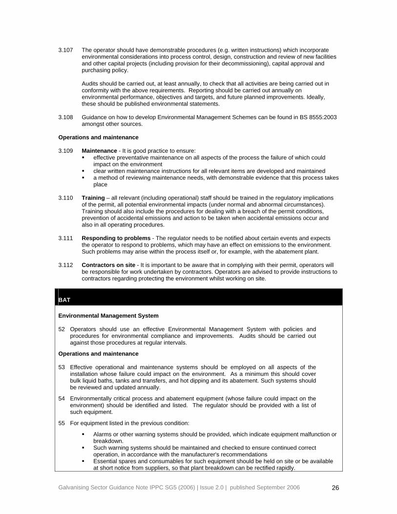
3.107
3.108
3.109
3.110
3.111
3.112
The operator should have demonstrable procedures (e.g. written instructions) which incorporate environmental considerations into process control, design, construction and review of new facilities and other capital projects (including provision for their decommissioning), capital approval and purchasing policy.
Audits should be carried out, at least annually, to check that all activities are being carried out in conformity with the above requirements. Reporting should be carried out annually on environmental performance, objectives and targets, and future planned improvements. Ideally, these should be published environmental statements.
Guidance on how to develop Environmental Management Schemes can be found in BS 8555:2003 amongst other sources.
Operations and maintenance
Maintenance - It is good practice to ensure: effective preventative maintenance on all aspects of the process the failure of which could
impact on the environment clear written maintenance instructions for all relevant items are developed and maintained a method of reviewing maintenance needs, with demonstrable evidence that this process takes
place Training – all relevant (including operational) staff should be trained in the regulatory implications of the permit, all potential environmental impacts (under normal and abnormal circumstances). Training should also include the procedures for dealing with a breach of the permit conditions, prevention of accidental emissions and action to be taken when accidental emissions occur and also in all operating procedures.
Responding to problems - The regulator needs to be notified about certain events and expects the operator to respond to problems, which may have an effect on emissions to the environment. Such problems may arise within the process itself or, for example, with the abatement plant.
Contractors on site - It is important to be aware that in complying with their permit, operators will be responsible for work undertaken by contractors. Operators are advised to provide instructions to contractors regarding protecting the environment whilst working on site.
BAT Environmental Management System 52
53
54
55
Operators should use an effective Environmental Management System with policies and procedures for environmental compliance and improvements. Audits should be carried out against those procedures at regular intervals.
Operations and maintenance
Effective operational and maintenance systems should be employed on all aspects of the installation whose failure could impact on the environment. As a minimum this should cover bulk liquid baths, tanks and transfers, and hot dipping and its abatement. Such systems should be reviewed and updated annually.
Environmentally critical process and abatement equipment (whose failure could impact on the environment) should be identified and listed. The regulator should be provided with a list of such equipment.
For equipment listed in the previous condition:
Alarms or other warning systems should be provided, which indicate equipment malfunction or breakdown.
Such warning systems should be maintained and checked to ensure continued correct operation, in accordance with the manufacturer's recommendations
Essential spares and consumables for such equipment should be held on site or be available at short notice from suppliers, so that plant breakdown can be rectified rapidly.
Galvanising Sector Guidance Note IPPC SG5 (2006) | Issue 2.0 | published September 2006 26

56
57
58
59
60
61
Records of breakdowns should be kept and analysed by the operator in order to eliminate common failure modes.
Competence and training
A competent person should be appointed to liaise with the regulator and the public with regard to complaints. The regulator should be informed of the designated individual(s).
A formal structure shall be provided to clarify the extent of each level of employee's responsibility with regard to the control of the process and its environmental impacts. This structure shall be prominently displayed within the process building at all times. Alternatively, there must be a prominent notice referring all relevant employees to where the information can be found.
Personnel at all levels shall be given training and instruction sufficient to fulfil their designated duties under the above structure. Details of such training and instruction shall be entered into the employees’ record and be made available for inspection by the regulator.
The potential environmental risks posed by the work of contractors should be assessed and instructions provided to contractors about protecting the environment while working on site.
Accidents/incidents/non conformance
There should be written procedures for investigating incidents, (and near misses) which may affect the environment, including identifying suitable corrective action and following up.
Raw Materials 3.113
3.114
3.115
3.116
This section covers the use of raw materials and water and the techniques for optimising their use and minimising their impact by selection (Energy and fuels are covered under Energy).
As a general principal, the operator will need to demonstrate the measures taken to: reduce the use of chemicals and other materials (Waste minimisation (optimising the use
of raw materials)) substitute with materials presenting lower risks to the environment understand the fate of by-products and contaminants and their environmental impact
Raw materials selection
Raw materials used in galvanizing processes consist of: zinc water hydrochloric acid sulphuric acid acid inhibitors fluxes degreasing solutions post treatment chemicals lubricating oils, hydraulic oils and fuel oils wire for jigging jigs
The criteria in Table 5 should be considered when selecting raw materials
Galvanising Sector Guidance Note IPPC SG5 (2006) | Issue 2.0 | published September 2006 27

Table 5: Selection of raw materials
Raw material Selection criteria
Primary zinc
High Grade (HG) or Special High Grade (SHG) zinc. (SHG is 99.995% pure zinc) Good Ordinary Brand Zinc was used and contained 98.5% zinc
Lead May be added to HG or SHG zinc grades to maintain the wetability of the molten zinc. Lead also assists in periodic dross removal
Secondary zinc Impurities are said to have little effect on emissions from galvanizing
Water Hydrochloric acid (most is coproduct) Limit organic content to limit odour Sulphuric acid Rarely used Acid inhibitors Proprietary inhibitors Fluxes: Choices include triple, double and single salt, low fuming, self buffering, filtering or not,
Commercial process requirements
Degreasing solutions: mostly alkali, some acid, some biological
Commercial process requirements
Post treatment chemicals 0.1% -0.3% Cr(VI) is common as it provides brightness, long-term storage and withstands quench bath temperatures Nonchrome passivators under development
Lubricating oils, hydraulic oils Commercial process requirements Wire for jigging Annealed mild steel Jigs Steel
Non-galvanizing jig materials are an emerging technology; they last much longer than steel, reduce zinc usage, improve energy efficiency, and reduce waste costs as they do not add zinc or iron to the pickle liquor. These advantages are weighed against higher capital cost
Fuel oil Sulphur content is limited by other Regulations* *Sulphur in liquid fuels regulations, Regulation 3 (3) states that combustion plant (other than new large combustion plant covered by the LCPD for which there is a separate provision) can burn heavy fuel oil with a sulphur content greater than 1% so long as the sulphur dioxide emissions from the plant is less than or equal to 1700mg/m3 at 3% oxygen dry. Defra is the enforcing authority for these regulations. 3.117 When selecting alternative raw materials, operators should ensure that decisions are taken on the
basis of their environmental impact, whilst not compromising galvanizing quality and product integrity.
BAT 62 The operator should adopt procedures to control the specification of those types of raw
materials with the main potential for environmental impact in order to minimise any potential environmental impact. An annual review of alternative raw materials should be carried out with regard to environmental impact.
Galvanising Sector Guidance Note IPPC SG5 (2006) | Issue 2.0 | published September 2006 28

Waste minimisation (optimising the use of raw materials) 3.118
3.119
3.120
3.121
3.122
3.123
3.124
3.125
3.126
3.127
3.128
Waste minimisation can be defined simply as: “a systematic approach to the reduction of waste at source, by understanding and changing processes and activities to prevent and reduce waste”.
A variety of techniques can be classified under the term waste minimisation and they range from basic housekeeping techniques through statistical measurement techniques, to the application of clean technologies.
Key operational features of waste minimisation should be: the ongoing identification and implementation of waste prevention opportunities the active participation and commitment of staff at all levels including, for example, staff
suggestion schemes monitoring of materials’ usage and reporting against key performance measures or
benchmarks
Using this information, opportunities for waste reduction, changes in process and improved efficiency should be generated and assessed, and an action plan prepared for the implementation of improvements.
The use and fate of all materials should be mapped onto a process flow diagram using data from the raw materials inventory and other company data as appropriate. Data should be incorporated for each principal stage of the operation in order to construct a mass balance for the installation. The mass balance can then be used to identify opportunities for improvements.
As the operator is not usually in control of the amount of, for example, millscale or oil on work brought to him, comparisons can be quite variable
Monitoring and mapping material usage in this way can be carried out to determine benchmarks in terms of the amount of any given raw material used per tonne of product manufactured. Assessment against benchmarks can reveal whether the process is being maintained “in control” or to trigger investigations in to why raw material usage is increasing.
The following benchmarks are typically used in the galvanizing sector for process control and waste minimisation: zinc used per tonne product acid consumption per tonne product water consumption per tonne product
There should be continuous movement towards more Sustainable Consumption and Production (i.e. doing more for less) as laid out in Government Guidance “ Changing Patterns - UK Government Framework for Sustainable Consumption and Production” (Ref 8). Section 3.3 of the guidance identifies advice and funding programmes available to achieve more sustainable production practices. The National Industrial Symbiosis Programme shares information across all industrial sectors to produce guidance and case studies for resource efficiency (Ref 8). See also Envirowise Guides (Ref 9) for information.
The following techniques would be expected to minimise waste arising:
Use of the Kleingarn system to manage acid
Jig materials that do not galvanize reduce waste production and provide savings in running costs: less zinc becomes waste; less heat is removed from the molten zinc bath; pickling/stripping costs are less, and opportunities for reuse of wastes increase. At the time this guidance was written, non-galvanizing jig material was an emerging technology and was being evaluated at several sites to see how the increase in jig cost compared against achievable savings, and what operational factors limited those savings.
BAT 63
64
The operator should record materials usage and waste generation in order to establish internal benchmarks. Assessments should be made against internal benchmarks to maintain and improve resource efficiency.
The operator should carry out a waste minimisation audit at least as frequently as the permit
Galvanising Sector Guidance Note IPPC SG5 (2006) | Issue 2.0 | published September 2006 29

review period. If an audit has not been carried out in the 2 years prior to submission of the application it should be completed within 18 months of the issue of the first PPC permit. The methodology used and an action plan for optimising the use of raw materials should be submitted to the regulator within 2 months of completion of the audit.
65 Specific improvements resulting from the recommendations of audits should be carried out within a timescale approved by the regulator.
Water use 3.129
3.130
3.131
3.132
3.133
Galvanizers on average use a much lower amount of water for each tonne of finished product as compared to the relatively much higher amount of water used by other metal finishing industries2. Water use should even so be minimised within the BAT criteria for the prevention or reduction of emissions and be commensurate with the prudent use of water as a natural resource.
Reducing water use may be a valid environmental and/or economic aim in itself, perhaps because of local supply constraints. Also, from the point of view of reducing polluting emissions, any water passing through an industrial process is degraded by the addition of pollutants, and there are distinct benefits to be gained from reducing the water used. These include: reducing the size of (a new) treatment plant, thereby supporting the cost benefit BAT
justification of better treatment cost savings where water is purchased or disposed of to another party associated benefits within the process such as reduced energy requirements for heating and
pumping, and reduced dissolution of pollutants into the water leading to reduced sludge generation in the effluent treatment plant
The use of a simple mass balance for water use may help to reveal where reductions can be made.
Advice on cost-effective measures for minimising water use can be found in Ref 9.
The following general principals should be applied in sequence to reduce emissions to water: water-efficient techniques should be used where possible water should be recycled within the process from which it issues, treating it first if necessary.
Where this is not practicable, it should be recycled to another part of the process which has a lower water quality requirement
The main uses for water are for degreasing, in acid baths, in flux solution and as a top up for evaporative losses in the post treatment operations. It can also be used as a scrubber medium in abatement plant.
The volumes of water used by an installation should normally be metered separately from domestic/office type uses on site so that water efficiency audits can be carried out and benchmarks can be set for optimal efficiency.
BAT
66
67
68
The operator should carry out a regular review of water use (water efficiency audit) at least as frequently as the permit review period. If an audit has not been carried out in the 2 years prior to submission of the application it should be completed within 18 months of the issue of the first PPC permit.
Using information from the water efficiency audit, opportunities for reduction in water use should be assessed and, where appropriate, should be carried out in accordance with a timescale approved by the regulator.
Information from audits should be used to establish benchmarks. Operators should keep records of such benchmarks and make measurement against them to reveal whether the process is being maintained “in control” or to track improvements.
2 For example, according to a study by Envirowise, half of galvanizers use 25 litres of water or less per tonne of finished product, compared with an average of 2000 litres of water per tonne used by other metal finishing industries. See EG046 Acid and Water Use in Galvanizing under Ref 9 and at www.envirowise.gov.uk
Galvanising Sector Guidance Note IPPC SG5 (2006) | Issue 2.0 | published September 2006 30

69
70
To initially establish the benchmarks, the volume of mains and abstracted water used in the activities should be directly measured when the installation is operating once a day for at least a fortnight. The fortnight selected should be when the installation is operating and should include an acid tank emptying and refilling. After the benchmarks have been established, measurements should be at a frequency of [taking account of how water usage compares to the industry average. For example, if water usage is higher than average then monitoring on a monthly basis may be required; or if water usage is at or below the average then monitoring on a two monthly basis or less may be appropriate]. All measurements should be recorded and the records held on site, in accordance with BAT 96.
Rinse water should be used for topping up pickling tanks.
Waste handling 3.134
3.135
3.136
Good segregation of materials is essential to facilitate opportunities for recovery, recycling and re-use and to maximise scope for good waste management.
Waste should be recycled or recovered unless a satisfactory justification has been accepted by the regulator that recovery is "technically and economically impossible”.
Other than spent acid which is tankered off-site, the most important wastes are: • particulate matter collected in bag or cartridge filters • ash and dross • scrubber liquors and sludges, and output from the effluent treatment plant • chemical and oil containers • general inert industrial waste
Environmental impact
Water: Not significant. Land: Scrubber sludge.
Air: Fugitive dust from handling and transfer.
Waste: Most galvanizing waste is recovered or recycled.
Energy: Not significant Accidents: Not significant Noise: Not significant
BAT
71
72
73
74
75
The operator should produce an inventory of the quantity, nature, origin and where relevant, the destination, frequency of collection, mode of transport and treatment method of any waste which is disposed of or recovered.
Operators should segregate the main waste types described in paragraph 3.136.
Operators should ensure that waste stored in containers that are durable for the substances stored and that incompatible waste types are kept separate.
Operators should ensure that waste storage areas are clearly marked and signed, and that containers are clearly labelled.
Ash, and any other potentially dusty materials, should be stored in such a manner as to prevent wind whipping and leaching to land or surface water. All such materials should be stored in covered containers or within an enclosed area, and handled in a manner that avoids
Galvanising Sector Guidance Note IPPC SG5 (2006) | Issue 2.0 | published September 2006 31

emissions of dust.
76
77
78
79
Ashes from the zinc bath should be kept dry at all times to avoid the risk of toxic arsine gas (arsenic trihydride) being formed.
The method of collection of waste from dry arrestment plant should be such that dust emissions are minimised.
A high standard of housekeeping should be maintained in areas where waste is handled.
Lorries transporting ash or other potentially dusty materials should be sheeted immediately after loading.
Waste re-use, recovery, recycling or disposal 3.137
3.138
3.139
3.140
Waste should be re-used, recovered or recycled unless the regulator has accepted a satisfactory BAT justification.
Table 6 summarises the routes currently taken by the various waste streams from a typical galvanizing site. Whether re-use, recovery or recycling is possible at a particular site will depend on the particular fuels and raw materials being used, the products being made and the methods of operation employed. The table reflects where recycling can be achieved when the appropriate combination of these factors is in place.
In the context of this note, recycling means the residue is returned to the process from where it has been produced, re-use means that the residue is used for another purpose
Markets are established for various galvanizing wastes. Operators should seek to establish markets for the recovery or recycling of other wastes generated within the installation. In addition, the Waste & Resources Action Programme (WRAP) researches and can provide guidance into recycling of other wastes such as wood, paper, cardboard and plastics (Ref 10 ).
Table 6: Solid waste stream: routes currently taken
Process waste stream
Fate
Ash consists mainly of zinc oxide. Most galvanizers extract as much zinc from the ash as they can. Techniques vary but include working the ash on the bath itself or using very small gas fired remelt furnaces. (emissions are extracted via abatement) The remainder of the ash is then sold for off-site for recycling. It is reported that no ash is landfilled.
Dross taken off-site and may be used as a feedstock for zinc oxide producers or may be reprocessed.
Flux skimmings sold onto recyclers Bag filter dust landfill Spent acid sent to licenced specialist treatment operators where it is neutralised using
alkaline waste from other industries; resulting salts then go to landfill. The spent acid, if zinc free or substantially zinc free, could be re-used as a raw material in the manufacture of a water treatment chemical, but this is still under development Recovering the acid value is not commercially viable at the time of writing.
Process liquids and associated sludges
including aqueous pre-flux, pickling, degreasing, rinse, and post treatment sludges Normally taken off-site as special waste. The quantity of this waste depends upon the quantity and nature of the input material and is benchmarked to production. Zinc chloride solution, if substantially free of iron, may be used for flux make-up or in the manufacture of zinc ammonium chloride fluxes.
Galvanising Sector Guidance Note IPPC SG5 (2006) | Issue 2.0 | published September 2006 32

BAT 80
81
The operator should carry out an annual review to demonstrate that the best environmental options are being used for dealing with the waste streams listed on Table 6.
if relevant - At a minimum of every two years, the operator should investigate potential markets for the recovery/re-use of wastes that are currently disposed of to landfill
Energy 3.141
3.142
3.143
BAT for energy efficiency under the PPC Regulations will be satisfied provided the operator meets the following conditions: either • the operator meets the basic energy efficiency requirements below and is a participant to a Climate Change Agreement (CCA) or a Direct Participation Agreement (DPA) with the Government or European Union Emission Trading Scheme (EUETS) commitments
or • the operator meets the basic energy efficiency requirements below and the additional energy efficiency requirements Energy used can be calculated from the gas bill and electricity bill and reported by tonnage throughput which might be described as either weight of galvanized product or pre-galvanized weight.
Basic energy efficiency requirements
The requirements of this section are basic, low cost, energy standards that apply whether or not a CCA or DPA is in force or the operator has EUETS commitments for the installation.
BAT
82
83
84
85
The operator should produce a report annually on the energy consumption of the installation.
The operator should monitor energy flows and target areas for reduction which should be updated annually. ("Sankey" diagrams and energy balances would be useful as aids.)
The operator should ensure that all plant is operated and maintained to optimise the use and minimise the loss of energy.
The operator should ensure that all appropriate containment methods are employed and maintained to minimise energy loss.
Additional energy efficiency requirements 3.144 3.145 3.146
Within IPPC it is valid to consider both the emission of direct (heat and emissions from on-site generation) and indirect (emissions from a remote power station) pollution when considering options for energy efficiency. At the time of writing, CHP is unlikely to be a viable option, but it should not be discounted for the future
Galvanising Sector Guidance Note IPPC SG5 (2006) | Issue 2.0 | published September 2006 33

BAT Energy efficiency techniques 86
87
The following techniques should be considered:
heat recovery from different parts of the processes minimisation of water use and closed circulating water systems good insulation plant layout to reduce pumping distances phase optimisation of electronic control motors and fans optimised efficiency measures for combustion plant e.g. air/feedwater preheating, excess
air etc. preventative maintenance programme targeting energy drops
Energy supply techniques
The following techniques should be considered:
use of Combined Heat and Power (CHP) generation of energy from waste use of less polluting fuels
Accidents 3.147
3.148
3.149
3.150
For accident management, there are three particular components: • identification of the hazards to the environment posed by the installation/activity • assessment of the risks (hazard x probability) of accidents and their possible consequences • implementation of measures to reduce the risks of accidents, and contingency plans for any accidents that occur Further guidance can be found in chapter 20 of the General Guidance Manual which provides guidance that may be relevant in the event of fire Ref 2. See also Ref 11 and Ref 12.
Identification of the hazards
In identifying the hazards, particular areas to consider may include, but should not be limited to, the following: Storage tanks and deliveries of process liquids and liquid wastes Storage tanks and deliveries of gas oil / derv Treatment baths Tanks of 0.1% -0.3% chromium (VI) (for comparison, the lower tier threshold for COMAH is 50
tonnes of 1% Cr(VI) at the time of writing) Identification of the risks
The hazards having been identified, the process of assessing the risks should address the following: how likely is the particular event to occur (source frequency)? what substances are released and how much of each (risk evaluation of the event)? where do the released substances end up (emission prediction - what are the pathways and
receptors)? what are the consequences (consequence assessment – what are the effects on the
receptors)? what is the overall risk (determination of overall risk and its significance to the environment)? what can prevent or reduce the risk (risk management – measures to prevent accidents and/or
reduce their environmental consequences)?
Galvanising Sector Guidance Note IPPC SG5 (2006) | Issue 2.0 | published September 2006 34
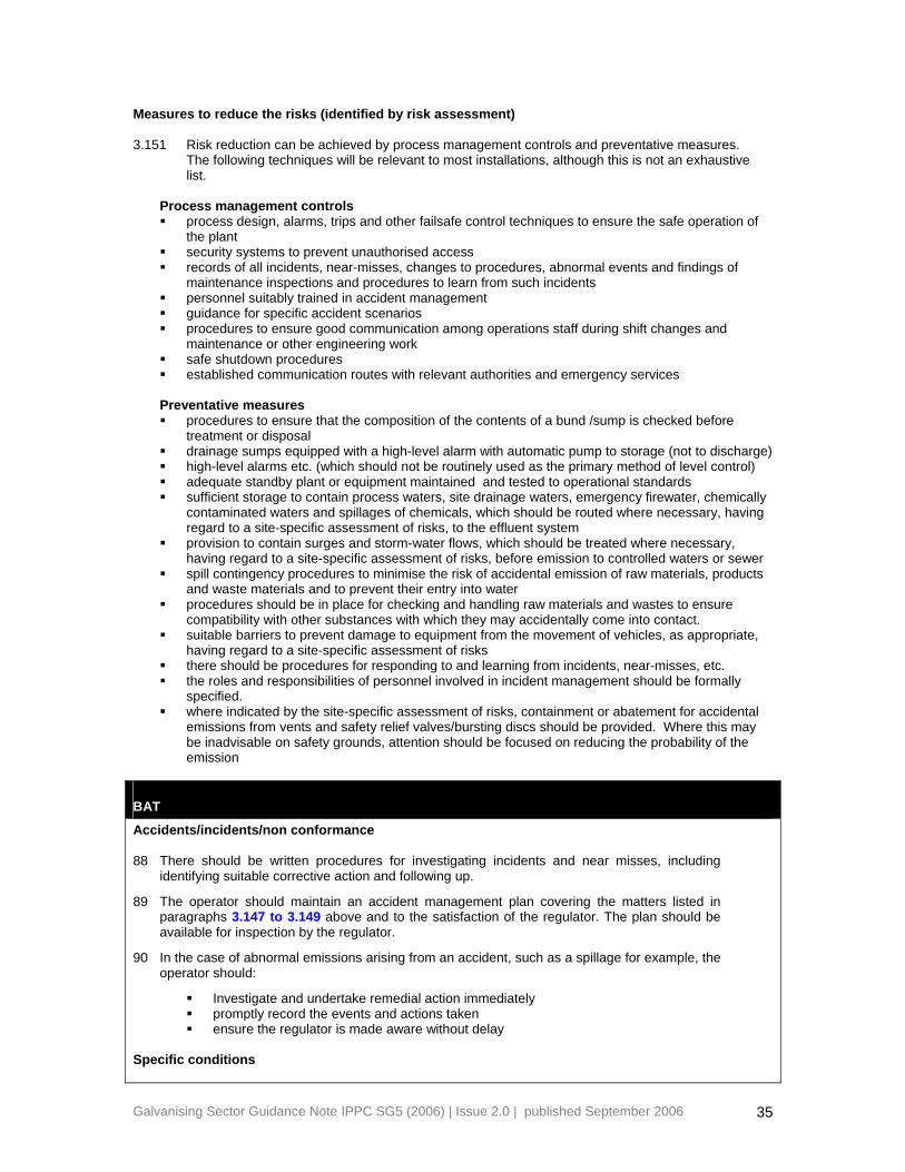
Measures to reduce the risks (identified by risk assessment) 3.151 Risk reduction can be achieved by process management controls and preventative measures.
The following techniques will be relevant to most installations, although this is not an exhaustive list.
Process management controls process design, alarms, trips and other failsafe control techniques to ensure the safe operation of
the plant security systems to prevent unauthorised access records of all incidents, near-misses, changes to procedures, abnormal events and findings of
maintenance inspections and procedures to learn from such incidents personnel suitably trained in accident management guidance for specific accident scenarios procedures to ensure good communication among operations staff during shift changes and
maintenance or other engineering work safe shutdown procedures established communication routes with relevant authorities and emergency services
Preventative measures procedures to ensure that the composition of the contents of a bund /sump is checked before
treatment or disposal drainage sumps equipped with a high-level alarm with automatic pump to storage (not to discharge) high-level alarms etc. (which should not be routinely used as the primary method of level control) adequate standby plant or equipment maintained and tested to operational standards sufficient storage to contain process waters, site drainage waters, emergency firewater, chemically
contaminated waters and spillages of chemicals, which should be routed where necessary, having regard to a site-specific assessment of risks, to the effluent system
provision to contain surges and storm-water flows, which should be treated where necessary, having regard to a site-specific assessment of risks, before emission to controlled waters or sewer
spill contingency procedures to minimise the risk of accidental emission of raw materials, products and waste materials and to prevent their entry into water
procedures should be in place for checking and handling raw materials and wastes to ensure compatibility with other substances with which they may accidentally come into contact.
suitable barriers to prevent damage to equipment from the movement of vehicles, as appropriate, having regard to a site-specific assessment of risks
there should be procedures for responding to and learning from incidents, near-misses, etc. the roles and responsibilities of personnel involved in incident management should be formally
specified. where indicated by the site-specific assessment of risks, containment or abatement for accidental
emissions from vents and safety relief valves/bursting discs should be provided. Where this may be inadvisable on safety grounds, attention should be focused on reducing the probability of the emission
BAT
Accidents/incidents/non conformance 88
89
90
There should be written procedures for investigating incidents and near misses, including identifying suitable corrective action and following up.
The operator should maintain an accident management plan covering the matters listed in paragraphs 3.147 to 3.149 above and to the satisfaction of the regulator. The plan should be available for inspection by the regulator.
In the case of abnormal emissions arising from an accident, such as a spillage for example, the operator should:
Investigate and undertake remedial action immediately promptly record the events and actions taken ensure the regulator is made aware without delay
Specific conditions
Galvanising Sector Guidance Note IPPC SG5 (2006) | Issue 2.0 | published September 2006 35

91
92
93
94
Operators should provide for safe storage and conveying systems for both liquid raw materials and wastes in order to minimise the potential for vandalism or accidental damage. Regular inspection should be carried out on pipelines, valves and pumps to inspect for damage and wear.
The operator should maintain procedures for the control of spills and of firewater to ensure containment and disposal of liquids in order to prevent or minimise pollution.
Operators should ensure that materials are charged into the correct silo or tank to minimise the potential for causing waste, spillage or uncontrolled chemical reaction.
Operators should design delivery routes to minimise accidental damage by vehicles to any storage facilities for liquids. Where a risk of vehicular damage to such storage areas has been identified, crash barriers should be fitted.
Noise and Vibration 3.152
3.153
3.154
3.155
3.156
Within this section, “noise” should be taken to refer to noise and/or vibration as appropriate, detectable beyond the site boundary. The most significant source of noise arises as a result of the following activities:
Where shot blasting and / or tube blowing are taking place there is a potential for significant noise release. Extraction fans, bag filter plant cleaning mechanisms and on-site vehicle movement (including audible alarms) are examples of noise sources that may also require consideration.
Noise surveys, measurement, investigation (which can involve detailed assessment of sound power levels for individual items of plant) or modelling may be necessary for either new or existing installations depending upon the potential for generating significant noise. Operators may have a noise management plan as part of their management system. Where an installation poses no risk of noise related environmental impact because the activities undertaken are inherently quiet or remote from receptors; these measures would not normally be required.
Following investigation of the impact of the installation, systems to minimise the environmental impact of the noisiest operations should be employed. The level of noise control required depends on the scale of operations and the proximity of operations to the public.
Further guidance can be found in chapter 16 of the General Guidance Manual.
BAT 95 The operator should identify key plant and equipment (or operations) with the potential to give
rise to significant noise and take such measures as are necessary by way of mitigation and maintenance of existing plant and equipment in order to minimise noise having regard to paragraph 3.153 of SG5 (2006).
Monitoring 3.157
3.158
This section describes general monitoring and reporting requirements for emissions to all environmental media. Guidance is provided for the selection of the appropriate monitoring methodologies, frequency of monitoring, compliance assessment criteria and environmental monitoring. The specific monitoring requirements with respect to emissions to air are described in Table 3.
Standards for monitoring equipment and procedures
The Environment Agency has introduced its Monitoring Certification Scheme (MCERTS) to improve the quality of monitoring data and to ensure that the instrumentation and methodologies employed for monitoring are fit for purpose.
Galvanising Sector Guidance Note IPPC SG5 (2006) | Issue 2.0 | published September 2006 36

operators should ensure their monitoring arrangements comply with the requirements of
MCERTS where available, e.g. using certified instruments and equipment, and using a registered stack testing organisation etc.
See http://www.environment-agency.gov.uk for listing of MCERTS equipment.
Sampling and analysis standards
The sampling analytical methods selected for compliance monitoring given in Table 3 and Appendix 2 should normally be used in the following order of priority:
3.159
3.160
3.161
3.162
3.163
3.164
3.165
3.166
Comité Européen de Normalisation (CEN) International Standardisation Organisation (ISO) British Standards Institution (BSI) United States Environmental Protection Agency (US EPA) American Society for Testing and Materials (ASTM) Deutsches Institut für Normung (DIN) Verein Deutcher Ingenieure (VDI) Association Française de Normalisation (AFNOR)
Guidance on standards for monitoring releases (to air, water and land) relevant to IPPC can be found in Ref 13 .
When selecting monitoring test methods, it is important to note that test methods are normally applicable to specific matrices (in relation to water) and concentrations of various pollutants (in relation to air). It is necessary to identify the most appropriate method in consideration of the hierarchy of methods. For example, if two methods are appropriate, the hierarchy is used to determine priority.
If in doubt the operator should consult the regulator.
Monitoring and sampling protocols
Where monitoring is needed the operator should devise a monitoring strategy to address the following: determinands to be monitored selection of monitoring points monitoring methods and procedures (selection of appropriate Standard Reference Methods) reference conditions and averaging periods measurement uncertainty of the proposed methods and the resultant overall uncertainty drift correction for continuous analysers quality assurance (QA) and quality control (QC) protocols, including accreditation and
certification equipment calibration and maintenance, sample storage and chain of custody/audit trail reporting procedures, data storage, interpretation and review of results, reporting format for the
provision of information to the regulator Monitoring frequency
The frequency of testing should be increased, for example, as part of the commissioning of new or substantially changed activities, or where the emission levels are near to or approach the emission limit.
Where non-continuous quantitative monitoring is required, the frequency may be varied. Where there is consistent compliance with emission limits, regulators may consider reducing the frequency. When determining ‘consistent compliance’ factors to consider include: the variability of monitoring results, for example, results which range from 15 - 45 mg/m3 ,
against an emission limit of 50 mg/m3 might not qualify for a reduction in monitoring the margin between the results and the emission limit, for example, results which range from
45 - 50 mg/m3 when the limit is 50 mg/m3 might not qualify for a reduction in monitoring Consistent compliance should be demonstrated using sequential results, for example, the results from at least three or more monitoring exercises within two years, or two or more monitoring
Galvanising Sector Guidance Note IPPC SG5 (2006) | Issue 2.0 | published September 2006 37

exercises in one year supported by continuous monitoring. Any significant process changes which might have affected the results should be taken into account.
3.167
3.168
3.169
3.170
3.171
3.172
3.173
Where effective surrogates are available they may be used to minimise monitoring costs.
Where monitoring shows that substances are not emitted in significant quantities, consideration can be given to a reduced monitoring frequency.
Monitoring emissions to air
The reference conditions of substances in releases to air from point sources are: temperature 273.15 K (0°C), pressure 101.3 kPa (1 atmosphere) and measured wet, no correction for water vapour. To convert measured values to reference conditions, see Technical Guidance Note M2 (Ref 13) for more information.
Monitoring emissions to water
The appropriateness of the monitoring requirements in Section 2 will vary depending upon the sensitivity of the receiving water and should be proportionate to the scale of the operations, nature of the discharge and receiving water. For each release point the following information is required: the specific volume flow from the process to sewer/controlled water the quality of the receiving water the volume of discharge compared to the percentage dry river flow of the receiving water
Environmental monitoring (beyond installation boundary)
Environmental monitoring may be required, for example, when: there are vulnerable receptors the emissions are a significant contributor to an Environmental Quality Standard (EQS) which
may be at risk the operator is looking for departures from standards based on lack of effect on the
environment the operator is required to validate modelling work
Further guidance is given in chapter 15 of the General Guidance Manual.
Monitoring of process variables
Some process variables will have potential environmental impact and these should be identified and monitored where they have an environmental relevance. Eg temperature of process tanks, iron content of pickle liquor.
BAT Monitoring and reporting 96
97
98
The operator should monitor emissions, make tests and inspections of the process and keep records; in particular the operator should keep records of audits, inspections, tests and monitoring, including all non-continuous monitoring, inspections and visual assessments. Monitoring may include process variables and operating conditions where relevant to emissions. In such cases:
current records should be kept on site and be made available for the regulator to examine records should be kept by the operator for at least two years
The operator should notify the regulator at least 7 days before any periodic monitoring exercise to determine compliance with emission limit values. The operator should state the provisional time and date of monitoring, pollutants to be tested and the methods to be used
The results of non-continuous emission testing should be forwarded to the regulator within 8
Galvanising Sector Guidance Note IPPC SG5 (2006) | Issue 2.0 | published September 2006 38

weeks of the completion of the sampling. Results from continuous monitoring systems should be recorded and be made available for inspection by the regulator.
99
100
101
102
103
104
105
106
107
108
109
110
111
112
All results submitted to the regulator should include details of process conditions at the time of monitoring, monitoring uncertainty as well as any deviations from the procedural requirements of standard reference methods and the error invoked from such deviations.
Results exceeding the emission limit value from any monitoring activity (both continuous and non-continuous) and malfunction or breakdown leading to abnormal emissions should be investigated and corrective action taken immediately. The operator should ensure that the regulator is notified without delay identifying the cause and corrective action taken. Where there is immediate danger to human health, operation of the activity should be suspended.
Sampling points on new plant should be designed to comply with CEN or Other Standards. e.g. BS EN 13284-1 or BS ISO 9096: 2003 for sampling particulate matter in stacks
if relevant - Continuous monitoring is normally expected for the main abated releases in Table 3. Where continuous monitoring is required by the permit instruments should be fitted with audible and visual alarms, situated appropriately to warn the operator of arrestment plant failure or malfunction, the activation of alarms should be automatically recorded and readings should be on display to appropriately trained operating staff
if relevant - All continuous monitors should be operated, maintained and calibrated (or referenced) in accordance with the appropriate standards and manufacturers' instructions, which should be made available for inspection by the regulator. Instruments should be operated to ensure less than 5% downtime over any 3-month period and all relevant maintenance and calibration (or referencing) should be recorded
Where available, operators should use monitoring equipment and instruments certified to MCERTS and use a stack-testing organisation accredited to MCERTS standards or such alternative requirements as approved by the regulator.
Monitoring and reporting of emissions to air
Exhaust flow rates of waste gases should be consistent with the efficient capture of emissions, good operating practice and meeting the requirements of the legislation relating to the workplace environment.
The introduction of dilution air to achieve emission concentration limits should not be permitted.
Dilution air may be added where justified for waste gas cooling or improved dispersion. In such cases, monitoring should be carried out upstream of the dilution air input or procedures designed to correct for the ratio of input air to the satisfaction of the regulator.
Monitoring to determine compliance with emission limit values should be corrected to the following standard reference conditions: temperature, 273.15 K (0ºC), pressures 101.3 kPa (1 atmosphere) and measured wet, no correction for water vapour.
Periodic visual assessment of releases should be undertaken as required by the regulator to ensure that all final releases are colourless, free from persistent visible emissions and free from droplets.
if relevant - Frequency of monitoring for all pollutants (including particulate matter) where arrestment equipment is necessary to meet specified emission limits should be at least annually.
Monitoring of process variables
Pickle liquor parameters should be monitored and recorded [on a regular basis eg weekly] to ensure optimum pickling rate is achieved as described in Appendix 3.
Monitoring and reporting emissions to water and sewer
The appropriateness of the monitoring requirements will vary depending upon the sensitivity of the receiving water and should be proportionate to the scale of the operations, nature of the
Galvanising Sector Guidance Note IPPC SG5 (2006) | Issue 2.0 | published September 2006 39

discharge and receiving water. For each release point the following information is required:
the specific volume flow from the process to sewer/controlled water the sensitivity of the receiving water the volume of discharge compared to the percentage dry river flow of the receiving water
113
114
115
Increased monitoring should be carried out where substances to which the local environment may be susceptible could be released from the installation. (e.g. where releases of common pesticides or metals such as zinc may occur. See Annex 9 of the General Guidance Manual ‘EC Environmental Quality Standards relevant to IPPC’ on pages 171- 178).
A full analysis, to include the substances listed in Schedule 5 of the Regulations, should be carried out annually on a representative sample from each release point, unless it is agreed with the regulator that this is inappropriate.
Monitoring and reporting of waste
The following should be monitored and recorded:
quantity nature and origin of the waste the physical description of the waste a description of the composition of the waste any relevant hazardous properties (hazard and risk phrases) European Waste Catalogue code handling precautions and substances with which it cannot be mixed
disposal routes for each waste category
Information Provisions 3.174
3.175
This guidance note contains many provisions relating to information. There are two general categories of information identified in this note: Reports or notifications Additional information
Reports are required and notifications are information that should be sent to the regulator at a frequency that is specified in this guidance. Such information provisions are summarised in Table 7a below.
Table 7a: Summary of Provisions for Reporting and Notification
BAT Clause
Provision Information Category
Frequency
BAT 29 Investigation of the cause and nature of any persistent visible emissions
Report Reactive
BAT 41 Record of fugitive emissions to air Submit records
Regularly, if required by permit
BAT 54 List of key process equipment and process and abatement equipment whose failure could impact on the environment
Send list Soon if not already done, and if it changes
BAT 57 Notification of appointed competent person to liaise with the regulator and the public with regard to complaints
Notification Soon if not already done, and if it changes
BAT 64 Waste minimisation audit: Send in methodology and action plan
Report Near to issue of permit, then generally every 6 years
BAT 67 Proposed timescale for water efficiency improvements, if any
Report Generally every 6 years
BAT 90 Investigation of abnormal emissions arising from an accident. Remedial action taken immediately. Prompt
Notification Reactive
Galvanising Sector Guidance Note IPPC SG5 (2006) | Issue 2.0 | published September 2006 40

recording of the events and actions taken. Notification of the regulator without delay*
BAT96 Notification at least 7 days before any periodic monitoring exercise to determine compliance with ELVs
Notification Reactive
BAT 98 Report of results from non-continuous emission testing forwarded to the regulator.
Report Annually or as permit specifies: Within 8 weeks of the completion of the sampling
BAT 100 Investigation of results exceeding an ELV from any monitoring activity and malfunction or breakdown leading to abnormal emissions. Corrective action taken immediately. Notification without delay* identifying the cause and corrective action taken.
Notification Reactive
*Without delay In most cases it should be enough to notify the local authority (by telephone or facsimile) within an hour of the start or detection of the emission. Local authorities will wish to consider what notification arrangements to require outside working hours.
Additional information relates to procedures or records (including details of assessments, investigations and audits). Such information should be held by the operator and be accessible so that the regulator may view the information. For much of the information, on-site inspection may be sufficient for the regulator, subject to the particular circumstances. Regulators may be more likely to ask operators to send them copies of those items marked with an asterisk. The majority of this information is likely to be the same as would be required in any event when using an effective EMS, so documents can be produced which serve both purposes.
3.176
3.177
3.178
Annex 4 of ISO 14001 gives some detailed examples of information and document control but by way of generality A.4.4 states that “The extent of the environmental management system documentation may differ from one organization to anther depending on (a) the size and type of organization and its activities, products of services, (b) the complexity of processes and their interactions, and (c) the competence of personnel
Examples of documents include - statements of policy, objectives and targets, - information on significant environmental impacts, - procedures, - process information, - organisational charts, - internal and external standards, - site emergency plans, and - records”
Relating to documentation, Annex I of the EC Regulation No 761/2001 on the eco-management and audit scheme (EMAS) states that “the organisation shall establish and maintain procedures for controlling all documents required by this International Standard…”. The Annex goes on to provide details on what is required and includes the following headings: - Structure and responsibility - Training, awareness and competence - Management review - Communication - Environmental management system documentation - Document control - Operational control - Emergency preparedness and response - Monitoring and measurement - Non-conformance and corrective and preventive action - Records - Environmental management system audit
Galvanising Sector Guidance Note IPPC SG5 (2006) | Issue 2.0 | published September 2006 41

Additional information provisions are summarised in Table 7b below. 3.179 Table 7b: Summary of Provisions for Additional Information 8Clause
Category
Subject
BAT 27 Procedures Able to demonstrate steps taken to minimize emissions at start-up, shutdown, change of fuel or load
BAT 43 Procedures Leak prevention from subsurface structures (control, maintenance and inspection).
BAT 48 Procedures Preventative maintenance programme for tanks bunds and sumps BAT 51 Procedures If required: Odour control improvement programme BAT 52 Procedures Environmental Management System. BAT 53, 55 Procedures Operational and maintenance systems for all aspects of the installation whose
failure could impact on the environment – annual review BAT 56 Procedures Analyse breakdown records for common mode failures BAT 58 Procedures Formal structure of employee's responsibility for process control and
environmental impacts and training provisions BAT 60 Procedures Instruct on-site contractors about their environmental risks and protection BAT 61 Procedures Investigating accidents, incidents and non-conformance BAT 62 Procedures Control the specification of raw materials with respect to their environmental
impact. Annual review of alternative raw materials BAT 63 Procedures Assess materials usage and waste generation against internal benchmarks BAT 64 Procedures Waste minimisation audit BAT 66 Procedures Water efficiency audit BAT 68 Procedures Assess operation against internal benchmarks BAT 80 Procedures Annual review of wastes; is best environmental option being used BAT 81 Procedures Investigate potential markets for wastes BAT 88 Procedures Incidents and near misses investigation. Corrective action and following up BAT 89 Procedures Accident management plan BAT 91 Procedures Safe storage and transfer systems for process liquids and wastes BAT 92 Procedures Spills and firewater control to ensure containment and disposal of liquids BAT 13 Records Iron content of flux solution, annual dross production BAT 16 Records Annual flux usage 3.90 Records Fugitive emissions to surface water, sewer and groundwater BAT 42 Records Diagrammatic route of all drains, subsurface pipework, sumps, and storage
vessels. Plus broadly, where they would leak to and where they flow to BAT 43 Records Drainage system inspection and maintenance BAT 44 Records Operational area surfacing: design, condition BAT 47 Records Tanks and connections: integrity BAT 48 Records Visual inspection of tanks, bunds and sumps BAT 50 Records Odour assessments BAT 52 Records Records of EMS audits BAT 56 Records Breakdowns BAT 58 Records Formal structure of employee's responsibility for process control and
environmental impacts and training provisions BAT 63 Records Materials usage, wastes generated BAT 68 Records Benchmarks BAT 69 Records Water used BAT 71 Records Waste disposed/recovered: Inventory BAT 82, 83 Records Energy audit and reduction plan; Annual BAT 90 Records Abnormal emissions; investigation, action,
Galvanising Sector Guidance Note IPPC SG5 (2006) | Issue 2.0 | published September 2006 42

BAT 95 Records Noise: Identification of key plant and equipment with the potential to give rise to significant noise. Mitigation measures
BAT 96 Records Monitoring, testing, inspection, assessments (incl visual), audit, process variables where relevant; Results
BAT 103 Records Maintenance and calibration of continuous monitoring systems BAT 111 Records Pickle liquor parameters BAT 112 Records Emissions to water parameters BAT 114 Records Analysis for Schedule 5 substances (where needed) BAT 115 Records Waste: monitoring and recording 3.180 The amount of information and size of reports or documents required under the information
provisions should be decided on a 'fit for purpose' basis. The label 'report' or 'record' should not be taken to imply that a sizeable document must be submitted if the required information can be provided in much shorter form. A report could comprise a paragraph or two if that was agreed to be sufficient for the purpose. Alternatively, lengthy documents may be necessary in particular circumstances.
All the information listed in Tables 7a and 7b is considered necessary either a) for regulators to keep a watch on the performance of an installation (e.g. monitoring data and
who is the competent person to liaise with over complaints) or on the operator's efforts to improve performance (e.g. waste minimisation and energy audits), and/or
b) for operators to maintain an appropriate level of control over the installation, and which regulators should have access to should they wish to check that the information is being properly kept or to examine the information for regulatory purposes.
Galvanising Sector Guidance Note IPPC SG5 (2006) | Issue 2.0 | published September 2006 43

References
Environment Agency documents referred to below are available from the Environment Agency website http://www.environment-agency.gov.uk. Many of the references below are being made available free of charge for viewing or download on the website. The same information can also be accessed via the SEPA website http://www.sepa.org.uk, or the NIEHS website www.ehsni.gov.uk
Ref 1 The Pollution Prevention and Control (England and Wales) Regulations (SI 1973 2000) as amended
(www.legislation.hmso.gov.uk) or the Scottish equivalent SSI 323 2000
Ref 2 Secretary of State's Guidance (England and Wales): General Guidance Manual on Policy and Procedures for A2 and B Installations , March 2003 - available from the Defra website and, in hard copy, from the Defra Publications line 08459 556000 www.defra.gov.uk/environment/ppc/index.htm
Ref 3 IPPC Reference Document on Best Available Techniques in the Ferrous Metals
Processing Industry European Commission http://eippcb.jrc.es Ref 4 Chemical storage tank systems – good practice. CIRIA July 2003 ISBN 0 860 17 598 7 Ref 5 "General Galvanizing Practice" produced by Galvanizers Association, 1999 revision, copyright- Galvanizers
Association.
Ref 6 HMIP Technical Guidance Note (Dispersion) D1, 1993 The Stationery Office ISBN 0 11 752794 7 www.environment-agency.gov.uk
Ref 7 AQ11(05) Regulating water discharges from A2 Installations Defra website www.defra.gov.uk/environment/ppc/index.htm
Ref 8 Management, Resource Efficiency and Waste Minimisation References Defra/DTI - Changing Patterns - UK Government Framework for Sustainable Consumption and Production
Sept 2003 National Industrial Symbiosis Programme www.nisp.org.uk/
Ref 9 'Envirowise (formerly the Environmental Technology Best Practice Programme, ETBPP), Harwell International
Business Centre, Didcot, Oxfordshire OX11 0QJ. Helpline 0800 585794. Good Practice Guides: www.envirowise.gov.ukWater efficiency references available from Envirowise: GG025, Saving money through waste minimisation: Raw Material Use GC22, Simple measures restrict water costs GG26, Saving money through waste minimisation: Reducing water use, GG26 EG046 Acid and Water Use in Galvanizing
Ref 10 Waste & Resources Action Programme (WRAP), The Old Academy, 21 Horse Fair, Banbury, Oxon OX16 0AH.
[email protected] Ref 11 BS 5908: Code of Practice for Fire Precautions in the Chemical and Allied Industries Ref 12 Environment Agency, Pollution Prevention Guidance Note - Pollution prevention measures for the control of
spillages and fire-fighting run-off, PPG 18, gives information on sizing firewater containment systems
Ref 13 Monitoring Guidance www.environment-agency.gov.uk M1 Sampling requirements for monitoring stack emissions to air from industrial installations, Environment
Agency July 2002 M2 Monitoring of stack emissions to air. Environment Agency October 2004 Guidance on sampling and testing of wastes to meet landfill waste acceptance procedures. Environment
Agency Version 4.3a December 2003 MCERTS approved equipment link via http://www.environment-agency.gov.uk/business" How
and why we regulate your business/Principles and approaches” Direct Toxicity Assessment for Effluent Control: Technical Guidance (2000), UKWIR 00/TX/02/07
Galvanising Sector Guidance Note IPPC SG5 (2006) | Issue 2.0 | published September 2006 44
Abbreviations BAT Best Available Techniques BOD Biochemical Oxygen Demand BREF BAT Reference Document CCA Climate Change Agreement CEM Continuous Emissions Monitoring CHP Combined Heat and Power plant CO2 Carbon Dioxide CO Carbon Monoxide COD Chemical Oxygen Demand COSHH Control of Substances Hazardous to Health Cr Chromium DPA Direct Participation Agreement EAL Environment Assessment Level ELV Emission Limit Value EMAS Eco-Management and Audit Scheme EMS Environmental Management System ETP Effluent Treatment Plant EU European Union EUETS European Union Emission Trading Scheme EQS Environmental Quality Standard HCl Hydrogen Chloride H2S Hydrogen Sulphide MCERTS Monitoring Certification Scheme NIEHS Northern Ireland Environment and Heritage Service SAC Special Areas of Conservation SECp Specific Energy Consumption SEPA Scottish Environment Protection Agency SO2 Sulphur Dioxide SPA Special Protection Area STW Sewage Treatment Works TSS Total Suspended Solids WAG Welsh Assembly Government ZAC Zinc Ammonium Chloride Zn Zinc
Galvanising Sector Guidance Note IPPC SG5 (2006) | Issue 2.0 | published September 2006 45

Appendix 1: Summary of Changes
Reasons for the main changes are summarised below. Table 8: Summary of changes
Section/ Paragraph/ Heading
Change Reason Comment
1. Introduction Table 1 Compliance timetable amended New provisions of note 2. Emission limits and other provisions Table 4 Zinc benchmark deleted Process liquids are not
discharged to surface water or sewer Rain runoff to surface water is being investigated and no BAT levels have been set yet
Historic assumptions are being re-examined; and cost/ benefit of treatment/prevention for discharges to surface water is currently being researched and is expected to lead to this guidance note being updated starting in October 2006.
3. Techniques for pollution control Installation description and in-process controls Table 5 and 3.128 Non-galvanizing jigs added New technology being
tried costs and benefits being evaluated by industry. Will be evaluated as a candidate for BAT alongside review of zinc/ammonia benchmarks starting in October 2006
3.19, 3.25, 3.28, 3.32, 3.63
Examine if extension of bunds for double dipping are needed
BAT Control of spillage/drips is considered more important now that fugitive emissions to water are being reassessed
BAT 36 Where necessary, treat runoff before discharge
BAT Upgrade time and BAT methods will be issued after this guidance is published.
Emissions Control BAT 35 Run off to surface waters should
be assessed to see if pollution prevention/treatment is needed
BAT As for zinc benchmark
3.88 & BAT 39 Point source emissions to groundwater
Amended text Groundwater Regulations - extra guidance to regulators and operators
3.90, 3.91 Fugitive emissions to air, Fugitive emissions to surface water, sewer and groundwater
BAT provisions amended BAT/industry good practice
3.100 to 3.104 Odour
Inclusion of paragraph on assessment,
Restructuring Sector Guidance - extra guidance to regulators and operators
BAT 50- 51 Odour
BAT provisions for odour control BAT/industry good practice
Not a problem at many sites
Management 3.107 and BAT 53 Additional BAT provision for
using effective EMS BAT/industry good practice
Galvanising Sector Guidance Note IPPC SG5 (2006) | Issue 2.0 | published September 2006 46

BAT 58-59
A formal organisational structure for environmental control
BAT/industry good practice
Raw Materials Table 5
New table for selection criteria for raw materials
Extra guidance to regulators and operators
3.127
Guidance on sustainable consumption and production
Extra guidance to regulators and operators
Government Policy
BAT 62 BAT provision – establishing Benchmarks for efficiency in raw materials usage
BAT/industry good practice
BAT 68
BAT provision – establishing benchmarks for water use
BAT/industry good practice
Waste Handling BAT 71-75 BAT provisions consolidated BAT/industry good
practice Seven BAT clauses reduced to 4 in light of review information
Waste re-use, recovery, recycling or disposal BAT 80, 81 BAT provisions to annually
review disposal options and to investigate new markets for waste recovery
BAT Envirowise and WRAP guides given as reference
3.128 New text re non-galvanizing Jigs Emerging technology being tried
Will be reviewed alongside zinc/ammonia benchmarks, starting in October 2006
Energy Accidents 3.147
Inclusion of text for identification of the sector specific hazards
Extra guidance to regulators and operators
BAT 91 to 94
Additional provisions – specific measures for accident prevention
Industry good practice
Noise and Vibration 3.152
Additional text BAT/industry good practice
Monitoring 3.160
Considering appropriateness when selecting test methods
Extra guidance to regulators and operators
BAT 99
Reporting monitoring uncertainty BAT
BAT 115
Waste reporting BAT/industry good practice
To assist in waste auditing to minimise the impact of waste to land
Information Provisions 3.172 to 3.178, Tables 7a and 7b
Additional text and new tables identifying information and reporting provisions
Extra guidance to regulators and operators
Lists should make it easier to use guidance
References Amended reference list New guidance available Appendix 1 and Table 8
New Appendix 1 included as a summary of changes
Appendix 2 List of water test methods Replacing old Appendix 1
Galvanising Sector Guidance Note IPPC SG5 (2006) | Issue 2.0 | published September 2006 47

Appendix 2: Some Common Monitoring Methods for Releases to Water Table 9: Measurement methods for common substances to water Determinand
Method Detection limit
Valid for range mg/l
Standard
Suspended solids
Filtration through glass fibre filters
2 mg/l 20% 10-40 ISO 11929:1997, EN872 - Determination of suspended solids
Total hydrocarbon oil
Infra Red Absorption and Gravimetry 1983
0.2mg/l
SCA blue book 77 ISBN 0117517283
pH BS 6068-2.50:1995, ISO 10523:1994 Temperature SCA temperature measurement for
Natural, Waste and Potable Waters and other items of interest in the Water and Sewage Disposal Industry ISBN 0117520179
Metals
Inductively coupled plasma atomic emission spectroscopy
BS EN ISO 11885:1998, BS 6068-2.60:1998 Determination of 33 elements by inductively coupled plasma atomic emission spectroscopy
Ammonia 0.1 – 1 mg/l
0.1 – 10 mg/l BS 6068: Section 2.11 1987, Method for the determination of ammonium: automated spectrometric detection
Total N Method using oxidative digestion with peroxodisulfate
0.02 mg/l.
0 – 5 ml/l, extended by dilution
BS EN ISO 11905-1:1998, BS 6068-2.62:1998 Water quality. Determination of nitrogen.
Galvanising Sector Guidance Note IPPC SG5 (2006) | Issue 2.0 | published September 2006 48

Appendix 3 Pickling Optimisation Curve Kleingarn claims that for efficient use of a pickle solution there is an optimum iron concentration (present as iron chloride) at a fixed temperature. Equally if the solubility limit of iron in HCl is exceeded then pickling will not take place. The graph below illustrates the optimum iron concentration which will give the maximum pickling rate at 20oC. Figure A3.1: Kleingarn pickling system
When a fresh pickle tank is set-up it will typically have a concentration of about 16% HCl with no iron present. From the graph above it can be seen that such a composition lies well below the optimum pickle rate line. As pickling proceeds the iron concentration of the pickle solution will increase as the acid strength decreases. Kleingarn suggests that in order to prevent the need for a fresh pickle solution to be made up, the spent pickle solution may be regenerated by the removal of a quantity of the spent acid and the addition of fresh acid.
Galvanising Sector Guidance Note IPPC SG5 (2006) | Issue 2.0 | published September 2006 49
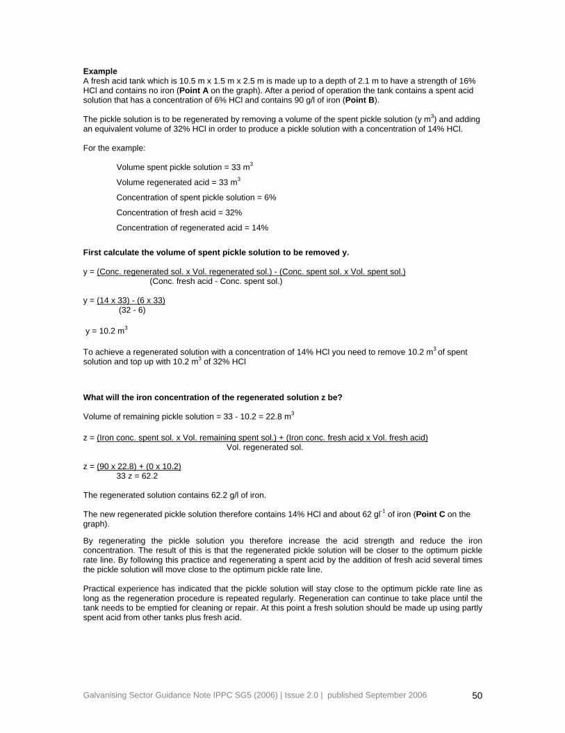
Example A fresh acid tank which is 10.5 m x 1.5 m x 2.5 m is made up to a depth of 2.1 m to have a strength of 16% HCl and contains no iron (Point A on the graph). After a period of operation the tank contains a spent acid solution that has a concentration of 6% HCl and contains 90 g/l of iron (Point B). The pickle solution is to be regenerated by removing a volume of the spent pickle solution (y m3) and adding an equivalent volume of 32% HCl in order to produce a pickle solution with a concentration of 14% HCl. For the example:
Volume spent pickle solution = 33 m3
Volume regenerated acid = 33 m3
Concentration of spent pickle solution = 6%
Concentration of fresh acid = 32%
Concentration of regenerated acid = 14%
First calculate the volume of spent pickle solution to be removed y. y = (Conc. regenerated sol. x Vol. regenerated sol.) - (Conc. spent sol. x Vol. spent sol.)
(Conc. fresh acid - Conc. spent sol.) y = (14 x 33) - (6 x 33) (32 - 6)
y = 10.2 m3
To achieve a regenerated solution with a concentration of 14% HCl you need to remove 10.2 m3 of spent solution and top up with 10.2 m3 of 32% HCl
What will the iron concentration of the regenerated solution z be?
Volume of remaining pickle solution = 33 - 10.2 = 22.8 m3
z = (Iron conc. spent sol. x Vol. remaining spent sol.) + (Iron conc. fresh acid x Vol. fresh acid) Vol. regenerated sol. z = (90 x 22.8) + (0 x 10.2)
33 z = 62.2
The regenerated solution contains 62.2 g/l of iron. The new regenerated pickle solution therefore contains 14% HCl and about 62 gl-1 of iron (Point C on the graph).
By regenerating the pickle solution you therefore increase the acid strength and reduce the iron concentration. The result of this is that the regenerated pickle solution will be closer to the optimum pickle rate line. By following this practice and regenerating a spent acid by the addition of fresh acid several times the pickle solution will move close to the optimum pickle rate line. Practical experience has indicated that the pickle solution will stay close to the optimum pickle rate line as long as the regeneration procedure is repeated regularly. Regeneration can continue to take place until the tank needs to be emptied for cleaning or repair. At this point a fresh solution should be made up using partly spent acid from other tanks plus fresh acid.
Galvanising Sector Guidance Note IPPC SG5 (2006) | Issue 2.0 | published September 2006 50