ippc s5.06 guidance for the recovery and disposal of ... · of hazardous and non hazardous waste...
TRANSCRIPT

www.environment-agency.gov.uk
Sector Guidance Note IPPC S5.06
of Hazardous and Non Hazardous Waste
Integrated Pollution Prevention and Control (IPPC)
Guidance for the Recovery and Disposal
Commissioning Organisation
Environment AgencyRio HouseWaterside DriveAztec WestAlmonds buryBristol BS32 4UDTel 01454 624400 Fax 01454 624409
© Environment AgencyFirst Published 2001ISBN 0
This document is Environment Agency copyright. We specifically allow the following:• Internal business or personal use. You may use this document for your own private use or for use within your busi-
ness without restriction.• Giving copies to others. You may do this without restriction provided that you make no charge.If you wish to use this document in any way other than as set out above including in particular for commercial gain, for example by way of rental, licence, sale or providing services you should contact:Liz GreenlandEnvironment AgencyCommercial Policy Unit2440 The QuadrantAztec WestAlmondsburyBristolBS32 4AQ
This is an uncontrolled document. To ensure you are using the latest version please check on any of the websites listed within the references.
Note: Queries about the content of the document should be made to Paul Fernee (01925 653999) or any member of the Waste PPC Process Team.Written comments or suggested improvements should be sent to Waste Permitting and Compliance Process at the Environment Agency by email at [email protected] or at: Waste PPC Permitting and Compliance ProcessEnvironment AgencyRio HouseWaterside DriveAztec WestAlmondsburyBristol BS32 4UD
Table 0.1: Record of changes
Version Date Change Template Version
Consultation July 2001 Draft for internal consultation
External consultation 2a October 2001 Amended following internal consultation
Issue 2 June 2002 Changes following external consultation. Styling changes
V2
Issue 3 October 2003 Changes following consultation V5
Recovery & Disposal of Hazardous & Non-hazardous Waste IPPC S5.06 | Issue 5 | Modified on 13 October, 2003i
Executive summary
This guidance has been produced by the Environment Agency for England and Wales and theNorthern Ireland Environment and Heritage Service (EHS).Together these are referred to as “the Regulator” throughout this document. Its publication follows consultation with industry, government departments and non-governmental organisations.
What is IPPC Integrated Pollution Prevention and Control (IPPC) is a regulatory system that employs an integrated approach to control the environmental impacts of certain industrial activities. It involves determining the appropriate controls for industry to protect the environment through a single Permitting process. To gain a Permit, Operators will have to show that they have systematically developed proposals to apply the Best Available Techniques (BAT) and meet certain other requirements, taking account of relevant local factors.
This Guidance and the BREF
This UK Guidance for delivering the PPC (IPPC) Regulations in this sector is based on the BAT Reference document BREF (see Ref. 1) produced by the European Commission. The BREF is the result of an exchange of information between member states and industry. The quality, comprehensiveness and usefulness of the BREF is acknowledged. This guidance is designed to complement the BREF and is cross-referenced to it throughout. It takes into account the information contained in the BREF and lays down the indicative standards and expectations in the UK (England and Wales, Scotland and Northern Ireland). The reader is advised to have access to the BREF.
The aims of this Guidance The aims of this Guidance are to:• provide a clear structure and methodology for Operators to follow to ensure they address all aspects
of the PPC Regulations and other relevant Regulations• minimise the effort by both Operator and Regulator in the permitting of an installation by expressing
the BAT techniques as clear indicative standards• improve the consistency of applications by ensuring that all relevant issues are addressed• increase the transparency and consistency of regulation by having a structure in which the Opera-
tor's response to each issue, and any departures from the standards, can be seen clearly and which enables applications to be compared
To assist Operators in making applications, separate, horizontal guidance is available on a range of topics such as waste minimisation, monitoring, calculating stack heights and so on. Most of this guidance is available free through the Environment Agency or EHS (Northern Ireland) websites (see References).
key environmental issues The key environmental issues for this sector are:• Waste hierarchy - appropriate measures must be taken against pollution and specifically that the
production of waste is avoided.• Waste characterisation sampling and checking - applicants will be required to demonstrate that
activities to screen waste will be carried out rigorously to ensure the effectiveness of waste treat-ment operations.
• Selection of appropriate treatment techniques - techniques should be designed and operated to avoid deliberate or inadvertent production and/or displacement of substances that may be harmful to the environment and to prevent the transfer of such substances from one environmental medium to another.
• Immobilisation process - applicants will be required to demonstrate the suitability of each waste stream for treatment of liquids with simple mixing processes.
• Intractable waste - under the Landfill Directive, the ban on landfilling of liquid wastes and other reg-ulatory changes will require alternative disposal routes to be sought for many of these wastes.
• Accumulations of waste - measures will need to be taken to identify a suitable disposal route prior to acceptance for wastes stored in drums.
• Accident risk - accident risks are increased through any failure in the management of waste.• Emissions to sewer - if BAT can achieve a higher level of removal of a substance from the aque-
ous effluent than may be required by the sewer discharge consent, BAT should be used.
Recovery & Disposal of Hazardous & Non-hazardous Waste IPPC S5.06 | Issue 5 | Modified on 13 October, 2003ii

• Odour associated with fugitive emissions - the handling of any substance that is or may contain a VOC will potentially lead to odour noticeable beyond the installation boundary.
• Site restoration (prevention of emissions to land) - IPPC in common with Waste Management Licensing requires that, on completion of activities, there should be no pollution risk from the site.
Recovery & Disposal of Hazardous & Non-hazardous Waste IPPC S5.06 | Issue 5 | Modified on 13 October, 2003iii
Contents
1 Introduction ............................................................................................................................... 1
1.1 Understanding IPPC......................................................................................................... 2
1.2 Making an application ...................................................................................................... 5
1.3 Installations covered ....................................................................................................... 6
1.4 Timescales......................................................................................................................... 91.4.1 Permit review periods............................................................................................. 91.4.2 Upgrading timescales for existing plant.................................................................. 9
1.5 Key issues........................................................................................................................ 11
1.6 Summary of releases ..................................................................................................... 14
1.7 Technical overview ......................................................................................................... 16
1.8 Economics ....................................................................................................................... 18
2 Techniques for pollution control ............................................................................... 20
2.1 In-process controls ......................................................................................................... 222.1.1 Pre-acceptance procedures to assess waste....................................................... 222.1.2 Acceptance procedures when waste arrives at the installation............................ 272.1.3 Waste storage ...................................................................................................... 342.1.4 Treatment - general principles.............................................................................. 402.1.5 Immobilisation ...................................................................................................... 462.1.6 Secondary liquid fuel ............................................................................................ 502.1.7 Oil processing....................................................................................................... 512.1.8 Biological process ................................................................................................ 532.1.9 Carbon absorption................................................................................................ 542.1.10 Wet air oxidation................................................................................................. 552.1.11 Air stripping ........................................................................................................ 552.1.12 Settlement .......................................................................................................... 552.1.13 Drum washing, crushing, shredding and cutting................................................. 562.1.14 Road tanker washing.......................................................................................... 582.1.15 Sludge treatment and disposal ........................................................................... 58
2.2 Emissions control............................................................................................................ 602.2.1 Point source emissions to air ............................................................................... 602.2.2 Point source emissions to surface water and sewer ............................................ 632.2.3 Point source emissions to groundwater ............................................................... 692.2.4 Fugitive emissions to air ....................................................................................... 702.2.5 Fugitive emissions to surface water, sewer and groundwater ............................. 722.2.6 Odour ................................................................................................................... 74
2.3 Management ................................................................................................................... 76
2.4 Raw materials.................................................................................................................. 792.4.1 Raw materials selection ....................................................................................... 792.4.2 Waste minimisation audit (minimising the use of raw materials) .......................... 812.4.3 Water use ............................................................................................................. 82
2.5 Waste handling ............................................................................................................... 84
2.6 Waste recovery or disposal........................................................................................... 85
2.7 Energy .............................................................................................................................. 862.7.1 Basic energy requirements (1) ............................................................................. 862.7.2 Basic energy requirements (2) ............................................................................. 872.7.3 Further energy efficiency requirements................................................................ 89
2.8 Accidents.......................................................................................................................... 90
2.9 Noise................................................................................................................................. 95
2.10 Monitoring ...................................................................................................................... 972.10.1 Emissions monitoring ......................................................................................... 972.10.2 Environmental monitoring (beyond installation)................................................ 1002.10.3 Monitoring of process variables........................................................................ 1012.10.4 Monitoring standards (Standard Reference Methods)...................................... 102
Recovery & Disposal of Hazardous & Non-hazardous Waste IPPC S5.06 | Issue 5 | Modified on 13 October, 2003iv

2.11 Closure ......................................................................................................................... 104
2.12 Installation issues ....................................................................................................... 106
3 Emission benchmarks .................................................................................................... 107
3.1 Emissions inventory ..................................................................................................... 107
3.2 Emission benchmarks.................................................................................................. 1093.2.1 Emissions to air associated with the use of BAT................................................ 1093.2.2 Emissions to water associated with the use of BAT........................................... 1103.2.3 Standards and obligations.................................................................................. 1103.2.4 Units for benchmarks and setting limits in Permits............................................. 1113.2.5 Statistical basis for benchmarks and limits in Permits........................................ 1123.2.6 Reference conditions for releases to air ............................................................. 112
3.3 Biological oxygen demand (BOD).............................................................................. 113
3.4 Chemical oxygen demand (COD) .............................................................................. 114
3.5 Halogens ........................................................................................................................ 115
3.6 Heavy metals................................................................................................................. 116
3.7 Nitrogen oxides ............................................................................................................. 117
3.8 Nutrients ......................................................................................................................... 118
3.9 Suspended solids ......................................................................................................... 119
3.10 Sulphur dioxide ........................................................................................................... 120
3.11 Volatile organic compounds (VOCs) ....................................................................... 121
4 Impact ...................................................................................................................................... 122
4.1 Impact assessment....................................................................................................... 122
4.2 The Waste Management Licensing Regulations .................................................... 124
4.3 The Habitats Regulations ............................................................................................ 125
References ............................................................................................................................ 126
Abbreviations ........................................................................................................................ 129
Appendix 1: Some common monitoring and sampling methods ................................. 130
Appendix 2: Equivalent legislation in Scotland & Northern Ireland ............................. 133
Appendix 3: Groundwater Regulations 1998 Schedule of listed substances and recommendations for List I (DEFRA) ........................................................................ 135
List of FiguresFigure 1.1: Main operations in waste treatment...................................................................................... 8Figure 2.1: Representation of acid neutralisation processes ................................................................ 46Figure 2.2: Emission summary for immobilisation processes ............................................................... 50Figure 2.3: Representation of an oil recovery process ......................................................................... 53Figure 2.4: Effluent management techniques ....................................................................................... 69
List of tablesTable 1.1:Potential pollutant releases................................................................................................... 14Table 1.2:Examples of activities in this sector ...................................................................................... 16Table 2.1:Minimum solubility and associated pH for metal hydroxides ................................................ 45Table 2.2:Minimum End-product specification ...................................................................................... 49Table 2.3:Emission Summary for immobilisation Processes ................................................................ 49Table 2.4:Emission Summary - Oil Re-processing ............................................................................... 52Table 2.5:Point Source Emissions to Air............................................................................................... 60Table 2.6:Air abatement options Key.................................................................................................... 61Table 2.7:VOCs benchmark releases ................................................................................................... 63Table 2.8:Point source emissions to water ........................................................................................... 64Table 2.9:Effluent management techniques ......................................................................................... 68
Recovery & Disposal of Hazardous & Non-hazardous Waste IPPC S5.06 | Issue 5 | Modified on 13 October, 2003v
Table 2.10:Examples of raw materials usage ....................................................................................... 80Table 2.11:Examples of Raw material substitutions ............................................................................. 81Table 2.12:Example format for energy efficiency plan.......................................................................... 87Table 2.13:Example format for energy efficiency plan.......................................................................... 88Table 2.14:Monitoring of process elements for emissions to water ...................................................... 98Table 2.15:Monitoring of process effluents released to sewer.............................................................. 98Table 2.16:Monitoring and reporting of emissions to air ....................................................................... 99Table 2.17:Monitoring of resource use ............................................................................................... 101Table 2.18:Monitoring of treatment process ....................................................................................... 102Table 3.1:Benchmark emission values ............................................................................................... 113Table 3.2:Extract from standards for residual chlorine ....................................................................... 115Table 3.3:Halogens benchmark emission values ............................................................................... 115Table 3.4:Extract from standards for heavy metals ............................................................................ 116Table 3.5:Extract from standards for heavy metals ............................................................................ 116Table 3.6:Heavy metals benchmark emission values......................................................................... 116Table 3.7:Nitrogen oxides benchmark emission values...................................................................... 117Table 3.8:Extracts from standards for nutrients .................................................................................. 118Table 3.9:Extracts from standards for nutrients .................................................................................. 118Table 3.10:Extracts from standards for suspended solids .................................................................. 119Table 3.11:Suspended solids benchmark emission values ................................................................ 119Table 3.12:Sulphur dioxide benchmark emission values.................................................................... 120Table 3.13:VOCs benchmark emission values ................................................................................... 121Table 4.1:Measurement methods for common substances to water .................................................. 130Table 4.2:Measurement methods for air emissions ............................................................................ 131Table 4.3:Equivalent legislation .......................................................................................................... 133
Recovery & Disposal of Hazardous & Non-hazardous Waste IPPC S5.06 | Issue 5 | Modified on 13 October, 2003vi

Recovery & Disposal of Hazardous & Non-hazardous Waste IPPC S5.06 | Issue 5 | Modified on 13 October, 2003

Introduction Techniques Emissions Impact
Understand- ing IPPC
Making an application
Installations covered
Timescales Key issues Summary of releases
Technical overview
Economics
Introduction
1 Introduction
The status and aims of this Guidance
This Guidance has been produced by the Environment Agency for England and Wales, and the Environment and Heritage Service (EHS) in Northern Ireland - each referred to as “the Regulator” in this document. Its publication follows consultation with industry, Government departments and non-governmental organisations.
It aims to provide Operators and the Regulator’s officers with advice on indicative standards of operation and environmental performance relevant to the industrial sector concerned, to assist the former in the preparation of applications for PPC Permits and to assist the latter in the assessment of those Applications (and the setting of a subsequent compliance regime). The use of techniques quoted in the guidance and the setting of emission limit values at the benchmark values quoted in the guidance are not mandatory, except where there are statutory requirements from other legislation. However, the Regulator will carefully consider the relevance and relative importance of the information in the Guidance to the installation concerned when making technical judgments about the installation and when setting Conditions in the Permit, any departures from indicative standards being justified on a site-specific basis.
The Guidance also aims (through linkage with the Application Form or template) to provide a clear structure and methodology for Operators to follow to ensure they address all aspects of the PPC Regulations and other relevant Regulations, that are in force at the time of writing. Also, by expressing the Best Available Techniques (BAT) as clear indicative standards wherever possible, it aims to minimise the effort required to permit an installation (by both Operator and Regulator).
Recovery & Disposal of Hazardous & Non-hazardous Waste IPPC S5.06 | Issue 5 | Modified on 13 October, 20031

Introduction Techniques Emissions Impact
Understand- ing IPPC
Making an application
Installations covered
Timescales Key issues Summary of releases
Technical overview
EconomicsUnderstanding IPPC
Introduction
1.1 Understanding IPPC
IPPC and the Regulations Integrated Pollution Prevention and Control (IPPC) is a regulatory system that employs an integrated approach to control the environmental impacts of certain listed industrial activities. It involves determination by the Regulator of the appropriate controls for those industries to protect the environment, through a single permitting process. To gain a Permit, Operators have to demonstrate in their Applications, in a systematic way, that the techniques they are using or are proposing to use, are the Best Available Techniques (BAT) for their installation, and meet certain other requirements, taking account of relevant local factors.
The essence of BAT is that the techniques selected to protect the environment should achieve an appropriate balance between environmental benefits and the costs incurred by Operators. However, whatever the costs involved, no installation may be permitted where its operation would cause significant pollution.
IPPC operates under IPPC Part A(1) Installations: Guide for (Applicants England and Wales) (includes Preparation of a Site Report in a Permit Application) (EA website). (for equivalent legislation in Scotland and N Ireland see Appendix 2). The three regional versions of the PPC Regulations implement in the UK the EC Directive on IPPC (96/61/EC). Further information on the application of IPPC/PPC, together with Government policy and advice on the interpretation of the English & Welsh Regulations, can be found in IPPC: A Practical Guide published by the Department for Environment, Food and Rural Affairs (Defra). The Department of the Environment, Northern Irelandhas published equivalent guidance on the N Ireland Regulations.
Installation based, NOT national emission limits
The BAT approach of IPPC differs from regulatory approaches based on fixed national emission limits (except where General Binding Rules or Standard Permits are issued). The legal instrument that ultimately defines BAT is the Permit, and Permits can only be issued at the installation level.
Indicative BAT Standards Indicative BAT standards are laid out in national guidance (such as this) and, where relevant, should be applied unless a different standard can be justified for a particular installation. BAT includes the technical components, process control, and management of the installation given in Section 2, and the benchmark levels for emissions identified in Section 3. Departures from those benchmark levels can be justified at the installation level by taking into account the technical characteristics of the installation concerned, its geographical location and the local environmental conditions. If any mandatory EU emission limits or conditions are applicable, they must be met, but BAT may go further (see “BAT and EQS” below).
Some industrial sectors for which national guidance is issued are narrow and tightly defined, whilst other sectors are wide and diffuse. This means that where the guidance covers a wide variety of processes, and individual techniques are not described in detail, the techniques (and their associated emission levels) which might constitute BAT for a particular operation, are more likely to differ, with justification, from the indicative BAT standards than would be the case for a narrow, tightly-defined sector.
BAT and EQS The BAT approach complements, but differs fundamentally from, regulatory approaches based on Environmental Quality Standards (EQS). Essentially, BAT requires measures to be taken to prevent emissions - and measures that simply reduce emissions are acceptable only where prevention is not practicable. Thus, if it is economically and technically viable to reduce emissions further, or prevent them altogether, then this should be done irrespective of whether or not EQSs are already being met. The BAT approach requires us not to consider the environment as a recipient of pollutants and waste, which can be filled up to a given level, but to do all that is practicable to minimise emissions from industrial activities and their impact. The BAT approach first considers what emission prevention can
Recovery & Disposal of Hazardous & Non-hazardous Waste IPPC S5.06 | Issue 5 | Modified on 13 October, 20032

Introduction Techniques Emissions Impact
Understand- ing IPPC
Making an application
Installations covered
Timescales Key issues Summary of releases
Technical overview
EconomicsUnderstanding IPPC
Introduction
reasonably be achieved (covered by Sections 2 and 3 of this Guidance) and then checks to ensure that the local environmental conditions are secure (see Section 4 on page 129 of this Guidance and also Guidance NoteIPPC Environmental Assessments for BAT). The BAT approach is therefore the more precautionary one because the release level achieved may be better than that simply required to meet an EQS.
Conversely, if the application of indicative BAT might lead to a situation in which an EQS is still threatened, a more effective technique is required to be BAT for that installation. The Regulations allow for expenditure beyond indicative BAT where necessary, and, ultimately, an installation will only be permitted to operate if it does not cause significant pollution.
Further advice on the relationship between BAT, EQSs and other related standards and obligations is given in IPPC: A Practical Guide, its Scottish equivalent, and also in Section 3.
Assessing BAT at the sector level
The assessment of indicative BAT takes place at a number of levels. At the European level, the European Commission issues a “BAT reference document” (BREF) for each main IPPC sector. It also issues “horizontal” BREFs for a number of general techniques which are relevant across a series of industrial sectors. The BREFs are the result of an exchange of information between regulators, industry and other interested parties in Member States. Member States should take them into account when determining BAT, but they are allowed flexibility in their application. UK Sector Guidance Notes like this one take account of information contained in relevant BREFs and set out current indicative standards and expectations in the UK. At national level, techniques that are considered to be BAT should represent an appropriate balance of costs and benefits for a typical, well-performing installation in the sector concerned. They should also be affordable without making the sector as a whole uncompetitive, either within Europe or world-wide.
Assessing BAT at the installation level
When assessing applicability of sectoral indicative BAT standards at the installation level, departures may be justified in either direction. Selection of the technique which is most appropriate may depend on local factors and, where the answer is not self-evident, an installation-specific assessment of the costs and benefits of the available options will be needed. The Regulator’s guidance IPPC Environmental Assessments for BAT and its associated software tool may help with the assessment. Individual installation or company profitability (as opposed to profitability of the relevant sector as a whole) is not a factor to be considered, however.
In the assessment of BAT at the installation level, the cost of improvements and the timing or phasing of that expenditure, are always factors to be taken into account. However, they should only be major or decisive factors in decisions about adopting indicative BAT where: • the installation’s technical characteristics or local environmental conditions can be shown to be so
different from those assumed in the sectoral assessment of BAT described in this guidance, that the indicative BAT standards may not be appropriate; or
• the BAT cost/benefit balance of an improvement only becomes favourable when the relevant item of plant is due for renewal/renovation (eg. change to a different design of furnace when the existing furnace is due for a rebuild). In effect, these are cases where BAT for the sector can be expressed in terms of local investment cycles; or
• a number of expensive improvements are needed. In these cases, a phasing programme may be appropriate - as long as it is not so drawn out that it appears to be rewarding a poorly performing installation.
In summary, departures by an individual installation from indicative BAT for its sector may be justified on the grounds of the technical characteristics of the installation concerned, its geographical location and the local environmental conditions - but not on the basis of individual company profitability, or if significant pollution would result. Further information on this can be found in IPPC: A Practical Guide and IPPC Part A(1) Installations: Guide for Applicants, or the equivalent Scottish Guidance.
Recovery & Disposal of Hazardous & Non-hazardous Waste IPPC S5.06 | Issue 5 | Modified on 13 October, 20033
Introduction Techniques Emissions Impact
Understand- ing IPPC
Making an application
Installations covered
Timescales Key issues Summary of releases
Technical overview
EconomicsUnderstanding IPPC
Introduction
Innovation The Regulators encourage the development and introduction of innovative techniques that advance indicative BAT standards criteria, ie. techniques which have been developed on a scale which reasonably allows implementation in the relevant sector, which are technically and economically viable and which further reduce emissions and their impact on the environment as a whole. One of the main aims of the PPC legislation is continuous improvement in the overall environmental performance of installations as a part of progressive sustainable development. This Sector Guidance Note describes the indicative BAT standards at the time of writing but Operators should keep up-to-date with improvements in technology - and this Guidance note cannot be cited as a reason for not introducing better available techniques. The technical characteristics of a particular installation may also provide opportunities not foreseen in the Guidance, and as BAT is determined at the installation level (except in the case of General Binding Rules (GBRs)), it is a requirement to consider these even where they go beyond the indicative Standards.
New installations Indicative BAT standards apply, where relevant, to both new and existing installations, but it will be more difficult to justify departures in the case of new installations (or new activities in existing installations) - and for new activities, techniques which meet or exceed indicative BAT requirements should normally be in place before operations start.
Existing installations - standards
For an existing installation, it may not be reasonable to expect compliance with indicative BAT standards immediately if the cost of doing so is disproportionate to the environmental benefit to be achieved. In such circumstances, operating techniques that are not at the relevant indicative BAT standard may be acceptable, provided that they represent what is considered BAT for that installation and otherwise comply with the requirements of the Regulations. The determination of BAT for the installation will involve assessment of the technical characteristics of the installation and local environmental considerations, but where there is a significant difference between relevant indicative BAT and BAT for an installation, the Permit may require further improvements on a reasonably short timescale.
Existing installations - upgrading timescales
Where there are departures from relevant indicative BAT standards, Operators of existing installations will be expected to have upgrading plans and timetables. Formal timescales for upgrading will be set as Improvement Conditions in the Permits. See Section 1.4.2 on page 9 for more details.
Recovery & Disposal of Hazardous & Non-hazardous Waste IPPC S5.06 | Issue 5 | Modified on 13 October, 20034
Introduction Techniques Emissions Impact
Understand- ing IPPC
Making an application
Installations covered
Timescales Key issues Summary of releases
Technical overview
EconomicsMaking an application
Introduction
1.2 Making an application
A satisfactory Application is made by: • addressing the issues in Sections 2 and 3 of this guidance;• assessing the environmental impact described in Section 4 (and in England and Wales Environ-
mental Assessment and Appraisal of BAT (IPPC H1));• demonstrating that the proposed techniques are BAT for the installation.
In practice, some Applicants have submitted far more information than was needed, yet without addressing the areas that are most important - and this has led to extensive requests for further information. In an attempt to focus application responses to the areas of concern to the Regulator, Application forms (templates) have been produced by the Environment Agency and by EHS inN Ireland. In addition, as the dates for application have approached, the operators in most industrial sectors in England and Wales have been provided with Compact Discs (CDs) which contain all relevant Application Forms, technical and administrative guidance, BREFs and Assessment tools, hyper-linked together for ease of use.
For Applicants with existing IPC Authorisations or Waste Management Licences, the previous applications may provide much of the information for the PPC application. However, where the submitted Application refers to information supplied with a previous application the Operator will need to send fresh copies - though for many issues where there is a tendency for frequent changes of detail (for example, information about the management systems), it will be more appropriate simply to refer to the information in the Application and keep available for inspection on site, up-to-date versions of the documents.
For further advice see IPPC Part A(1) Installations: Guide for Applicants (for England and Wales) or PPC Part A Installations: Guide for Applicants (for Scotland) or the equivalent Northern Ireland guide for Applicants.
Recovery & Disposal of Hazardous & Non-hazardous Waste IPPC S5.06 | Issue 5 | Modified on 13 October, 20035

Introduction Techniques Emissions Impact
Understand- ing IPPC
Making an application
Installations covered
Timescales Key issues Summary of releases
Technical overview
EconomicsInstallations covered
Introduction
1.3 Installations covered
This Guidance relates to installations containing the activities listed below, as described in Part A(1) of Schedule 1 to the IPPC Part A(1) Installations: Guide for (Applicants England and Wales) (includes Preparation of a Site Report in a Permit Application) (EA website).. The schedules of listed activities are slightly different in Scotland and Northern Ireland so for their equivalent Regulations see Appendix 2
Disposal of Waste Other Than by Incineration or Landfill
Part A(1)
(a) The disposal of hazardous waste (other than by incineration or landfill) in a facility with a capacity of more than 10 tonnes per day.
(b) The disposal of waste oils (other than by incineration or landfill) in a facility with a capacity of more than 10 tonnes per day.
(c) Disposal of non-hazardous waste in a facility with a capacity of more than 50 tonnes per day by -
(i) biological treatment, not being treatment specified in any paragraph other than paragraph D8 of Annex IIA to Council Directive 75/442/EEC, which results in final compounds or mixtures which are discarded by means of any of the operations numbered D1 to D12 in that Annex (D8); or
(ii) physico-chemical treatment, not being treatment specified in any paragraph other than paragraph D9 in Annex IIA to Council Directive 75/442/EEC, which results in final compounds or mixtures which are discarded by means of any of the operations numbered D1 to D12 in that Annex (for example, evaporation, drying, calcination, etc.) (D9).
Interpretation of Part A(1)
1. In this Part -
"disposal" in paragraph (a) means any of the operations described in Annex IIA to Council Directive 75/442/EEC on waste;
"hazardous waste" means waste as defined in Article 1(4) of Council Directive 91/689/EEC.
2. Paragraph (b) shall be interpreted in accordance with Article 1 of Council Directive 75/439/EEC.
3. Nothing in this Part applies to the treatment of waste soil by means of mobile plant.
4. The reference to a D paragraph number in brackets at the end of paragraphs (c)(i) and (ii) is to the number of the corresponding paragraph in Annex IIA to Council Directive 75/442/EEC on waste (disposal operations).
Section 5.4 - Recovery of Waste
Part A(1)
(c) Unless carried out as part of any other Part A activity, recovering hazardous waste in plant with a capacity of more than 10 tonnes per day by means of the following operations -
(i) the use principally as a fuel or other means to generate energy (R1);
(ii) solvent reclamation/regeneration (R2);
(iii) recycling/reclamation of inorganic materials other than metals and metal compounds (R5);
(iv) regeneration of acids or bases (R6);
(v) recovering components used for pollution abatement (R7);
Recovery & Disposal of Hazardous & Non-hazardous Waste IPPC S5.06 | Issue 5 | Modified on 13 October, 20036

Introduction Techniques Emissions Impact
Understand- ing IPPC
Making an application
Installations covered
Timescales Key issues Summary of releases
Technical overview
EconomicsInstallations covered
Introduction
(vi) recovery of components from catalysts (R8);
(vii) oil re-refining or other reuses of oil (R9).
Interpretation of Part A(1)
1. Nothing in paragraphs (a) and (b) of this Part applies to -
(a) distilling oil for the production or cleaning of vacuum pump oil; or
(b) an activity which is ancillary to and related to another activity, whether described in this Schedule or not, which involves the production or use of the substance which is recovered, cleaned or regenerated, except where the activity involves distilling more than 100 tonnes per day.
2. Nothing in this Part applies to the treatment of waste soil by means of mobile plant.
3. The reference to a R paragraph number in brackets at the end of paragraphs (c)(i) to (vii) is to the number of the corresponding paragraph in Annex IIB of Council Directive 75/442/EEC on waste (recovery operations).
The installation will also include associated activities which have a technical connection with the main activities and which may have an effect on emissions and pollution, as well as the main activities described above. These may involve activities such as: • the storage and handling of raw materials;• the storage and despatch of finished products, waste and other materials;• the control and abatement systems for emissions to all media;• waste treatment or recycling.
Environment Agency advice on the composition of English or Welsh installations and which on-site activities are to be included within it (or them) is given in its guidance document . Operators are advised to discuss the composition of their installations with the Regulator before preparing their Applications.
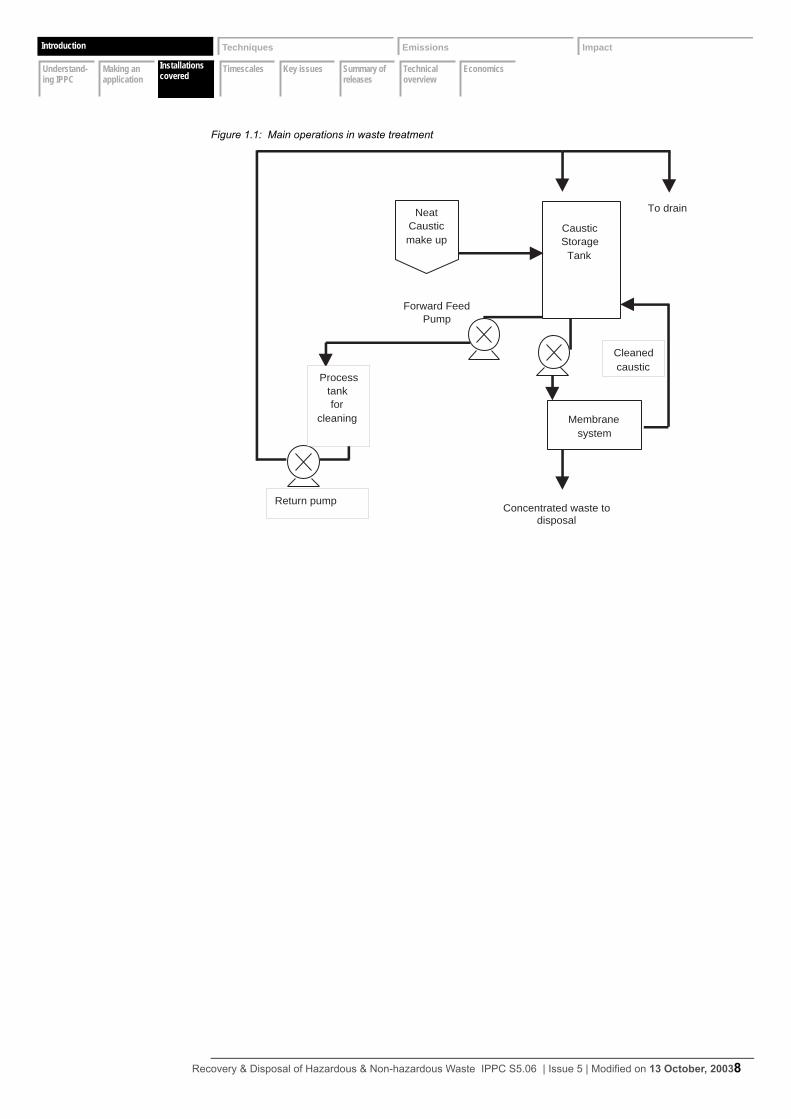
Figure 1.1 illustrates the main operations. For information on the types of activities covered by this document, see Section 1.7 on page 16.
Recovery & Disposal of Hazardous & Non-hazardous Waste IPPC S5.06 | Issue 5 | Modified on 13 October, 20037
Introduction Techniques Emissions Impact
Understand- ing IPPC
Making an application
Installations covered
Timescales Key issues Summary of releases
Technical overview
EconomicsInstallations covered
Introduction
Figure 1.1: Main operations in waste treatment
Concentrated waste todisposal
Forward FeedPump
Return pump
NeatCausticmake up
Membranesystem
To drain
CausticStorage
Tank
Cleanedcaustic
Processtankfor
cleaning
Recovery & Disposal of Hazardous & Non-hazardous Waste IPPC S5.06 | Issue 5 | Modified on 13 October, 20038
Introduction Techniques Emissions Impact
Understand- ing IPPC
Making an application
Installations covered
Timescales Key issues Summary of releases
Technical overview
EconomicsTimescales
Introduction
1.4 Timescales
1.4.1 Permit review periods
Permits are likely to be reviewed as follows:• for individual activities not previously subject to regulation under IPC or Waste Management Licens-
ing, a review should be carried out within four years of the issue of the PPC Permit• for individual activities previously subject to regulation under IPC or Waste Management Licensing,
a review should be carried out within six years of the issue of the IPPC Permit
However, where discharges of Groundwater List I or List II substances have been permitted, or where there is disposal of any matter that might lead to an indirect discharge of any Groundwater List I or II substance, a review must be carried out within four years as a requirement of the Groundwater Regulations.
These periods will be kept under review and, if any of the above factors change significantly, they may be shortened or extended.
1.4.2 Upgrading timescales for existing plant
Existing installation timescales
Unless subject to specific conditions elsewhere in the Permit, upgrading timescales will be set in the Improvement Programme of the Permit, having regard to the criteria for improvements in the following two categories:1 Standard “good-practice” requirements, such as, management systems, waste, water and energy
audits, bunding, housekeeping measures to prevent fugitive or accidental emissions, good waste-handling facilities, and adequate monitoring equipment. Many of these require relatively modest capital expenditure and so, with studies aimed at improving environmental performance, they should be implemented as soon as possible and generally well within 3 years of issue of the Permit.
2 Larger, more capital-intensive improvements, such as major changes to reaction systems or the installation of significant abatement equipment. Ideally these improvements should also be com-pleted within 3 years of Permit issue, particularly where there is considerable divergence from rele-vant indicative BAT standards, but where justified in objective terms, longer time-scales may be allowed by the Regulator.
Local environmental impacts may require action to be taken more quickly than the indicative timescales above, and requirements still outstanding from any upgrading programme in a previous permit should be completed to the original time-scale or sooner. On the other hand, where an activity already operates to a standard that is close to an indicative requirement a more extended time-scale may be acceptable. Unless there are statutory deadlines for compliance with national or international requirements, the requirement by the Regulator for capital expenditure on improvements and the rate at which those improvements have to be made, should be proportionate to the divergence of the installation from indicative standards and to the environmental benefits that will be gained.
Recovery & Disposal of Hazardous & Non-hazardous Waste IPPC S5.06 | Issue 5 | Modified on 13 October, 20039

Introduction Techniques Emissions Impact
Understand- ing IPPC
Making an application
Installations covered
Timescales Key issues Summary of releases
Technical overview
EconomicsTimescales
Introduction
The Operator should include in the Application a proposed programme in which all identified improvements (and rectification of clear deficiencies) are undertaken at the earliest practicable opportunities. The Regulator will assess BAT for the installation and the improvements that need to be made, compare them with the Operator’s proposals, and then set appropriate Improvement Conditions in the Permit
Recovery & Disposal of Hazardous & Non-hazardous Waste IPPC S5.06 | Issue 5 | Modified on 13 October, 200310

Introduction Techniques Emissions Impact
Understand- ing IPPC
Making an application
Installations covered
Timescales Key issues Summary of releases
Technical overview
EconomicsKey issues
Introduction
1.5 Key issues
Relationship to BATTreatment has competed with landfill for the disposal of many wastes, which has exercised a strong downwards pressure on process. The requirements of PPC and the Landfill Directive will result in waste disposal activities being directed by the need for regulatory compliance and higher standards of environmental protection, and therefore require significant adjustment by the industry. An assessment of the appropriate measures including BAT will be needed to support any application.
Waste hierarchyBoth IPPC and the Waste Framework Directive (WFD) (75/442/EEC as amended) require that appropriate measures be taken against pollution and specifically that the production of waste is avoided. Where waste is produced, the WFD requires that waste be recovered, re-used or used as a source of energy in preference to disposal. The requirement to demonstrate BAT is a new requirement.
With regard to the waste treatment activities involving disposal this raises the question of whether these activities constitute the appropriate means of dealing with the waste. Clearly, where an opportunity to recover a waste exists, then disposal or treatment may not be the appropriate measure.
This document assumes that the treatment and disposal activities covered do have a role to play, but will identify activities where the fundamental question arises of whether a particular waste should have reached the activity. The document will therefore not generally question whether waste treatment per se is Best Practicable Environmental Option (BPEO). It will only consider whether the various techniques and their components are appropriate measures to prevent and control pollution.
Waste characterisation, sampling and checkingThe rigour with which these aspects are conducted is essential to waste management operations. Failure to screen waste samples adequately prior to acceptance and to confirm the composition on arrival at the installation has historically led to subsequent problems, which include inappropriate storage and mixing of incompatible substances, accumulation of wastes and unexpected treatment characteristics. Applicants will therefore be required to demonstrate that these activities will be carried out rigorously to ensure their effectiveness.
Selection of appropriate treatment techniquesIn assessing the treatment options to determine BAT the effectiveness of the technique in destroying hazardous substances, reducing hazard and rendering substances suitable for release to other processes must be considered.
For the waste sector in particular, because of the variable and complex composition of many waste streams, not only primary hazards but also secondary hazards must be considered.
Techniques should be designed and operated to avoid deliberate or inadvertent production and/or displacement of substances that may be harmful to the environment and to prevent the transfer of such substances from one environmental medium to another.
However, it is also recognised that, to be viable, commercial waste treatment facilities must deal with variable waste steams, and it would not always be desirable or effective to over complicate the design and operation of a waste treatment process. Any determination of BAT cannot be simply seen as a means of implementing the highest available levels of technology.
Recovery & Disposal of Hazardous & Non-hazardous Waste IPPC S5.06 | Issue 5 | Modified on 13 October, 200311
Introduction Techniques Emissions Impact
Understand- ing IPPC
Making an application
Installations covered
Timescales Key issues Summary of releases
Technical overview
EconomicsKey issues
Introduction
Merchant waste treatment has to deal with a wide and variable range of wastes. This requires plant and equipment that is versatile and can be used for a number of wastes. This contrasts with treatment techniques used for “in-house” treatment on producer premises, where the number of waste streams is limited and well characterised. This may lend itself to the development of dedicated single-stream treatment techniques.
Immobilisation processesHistorically there has been a proliferation of such processes, most using in the main simple mixing processes to combine waste liquids that may be unsuitable for direct landfill with dry wastes such as pulverised fuel ash (PFA), cement dust or sawdust.
Applicants (for both new processes and Operators of existing processes) will be required to demonstrate the suitability of each waste stream for treatment by this process, to show how the effectiveness of the process has been maximised and to ensure the process can meet a standard product specification.
Article 2 of the Landfill Directive defines treatment as: “the physical, thermal, chemical or biological processes, including sorting, that change the characteristics of the waste in order to reduce its volume or hazardous nature, facilitate its handling or enhance recovery.” Article 5(4) is also crucial in relation to stabilisation, as it provides that: “the dilution or mixing of waste solely in order to meet the waste acceptance criteria is prohibited.”
A role may remain for “stabilisation” and “solidification” techniques under the new regime. However, these processes will be subjected to much stricter regulation, and their continued operation will be subject to the need to demonstrate BAT as described in the sections above.
Intractable wastesLandfill and stabilisation processes have been relied on for the disposal of intractable wastes which are difficult to treat and expensive to incinerate. These include:• solid cyanides• oxidising agents• chelating agents• high COD wastes• wastes containing low-flashpoint solvents
Under the Landfill Directive, the ban on landfilling of liquid wastes and other regulatory changes will require alternative disposal routes to be sought for many of these wastes. The development of new and effective treatments for these wastes will be a major challenge for the industry.
Accumulations of wasteFailure to ensure adequate throughput of wastes has led to the storage of large numbers of drums on some sites. Wastes involved are typically unchecked and drums are left to deteriorate. Such situations are often associated with large-scale site clearances and can be accompanied by competitive pressures and customer insistence to accept additional waste streams. Typically the wastes involved are difficult to handle and/or treat and may have been transferred between various Operators, with a consequent loss of information relating to original producer and composition. Under the new regime, Applicants will be required to demonstrate the efficient and effective processing of waste. A new requirement will be the need to have measures to identify a suitable disposal route prior to acceptance. Financial provision will be brought in for those sites previously benefiting from existing user rights.
Accident riskAccident risk is inherent when dealing with waste and in particular hazardous waste. Wastes are heterogeneous in nature and are often intrinsically aggressive to plant and equipment. Any failure in the management of the waste, from the process of characterisation and checking of wastes, to operational
Recovery & Disposal of Hazardous & Non-hazardous Waste IPPC S5.06 | Issue 5 | Modified on 13 October, 200312
Introduction Techniques Emissions Impact
Understand- ing IPPC
Making an application
Installations covered
Timescales Key issues Summary of releases
Technical overview
EconomicsKey issues
Introduction
control for reactions and mixing of wastes, will significantly increase the risk from unwanted or runaway reactions. Combinations of inappropriate equipment and poor inspection and maintenance procedures also increase the accident risk through, for example, tank overfill situations where level indicators may not be working or have not been correctly calibrated.
Emissions to sewerMost waste treatment installations have a sewer connection for the emission of aqueous effluents. Consents to discharge are set (in most cases) by sewerage undertakers. Although the consents limit the amount of pollutants dependent on the receiving wastewater treatment works (WwTW), this allows the releases of significant quantities of pollutants. Historically, the discharge consent has effectively set the standards for the emitting activities, however, this emphasis should change under IPPC, where emissions are determined by applying BAT to reach the most effective standard of pollution control. Consequently, if BAT can achieve a higher level of removal of a substance from the aqueous effluent than may be required by the sewer discharge consent, BAT should be used.
Odour associated with fugitive emissionsThe handling of any substance that is or may contain a VOC (or other odorous substances, for example, mercaptans or other sulphur-containing compounds) will potentially lead to odour noticeable beyond the installation boundary, even at concentrations that may be well below nominal emission limit values (ELV). Odours may arise from storage, transfer or bulking up of wastes containing VOC or other odorous substances. Failure to adequately inspect and maintain plant and equipment is also a contributory cause to fugitive emissions, e.g. leaks from pumps.
Site restoration (prevention of emissions to land)IPPC in common with Waste Management Licensing requires that, on completion of activities, there should be no pollution risk from the site. To prevent short- and long-term contamination of the site requires provision and maintenance of surfacing of operational areas, measures to prevent or quickly clear away leaks and spillages, maintenance of drainage systems and other subsurface structures.
Recovery & Disposal of Hazardous & Non-hazardous Waste IPPC S5.06 | Issue 5 | Modified on 13 October, 200313
Introduction Techniques Emissions Impact
Understand- ing IPPC
Making an application
Installations covered
Timescales Key issues Summary of releases
Technical overview
EconomicsSummary of releases
Introduction
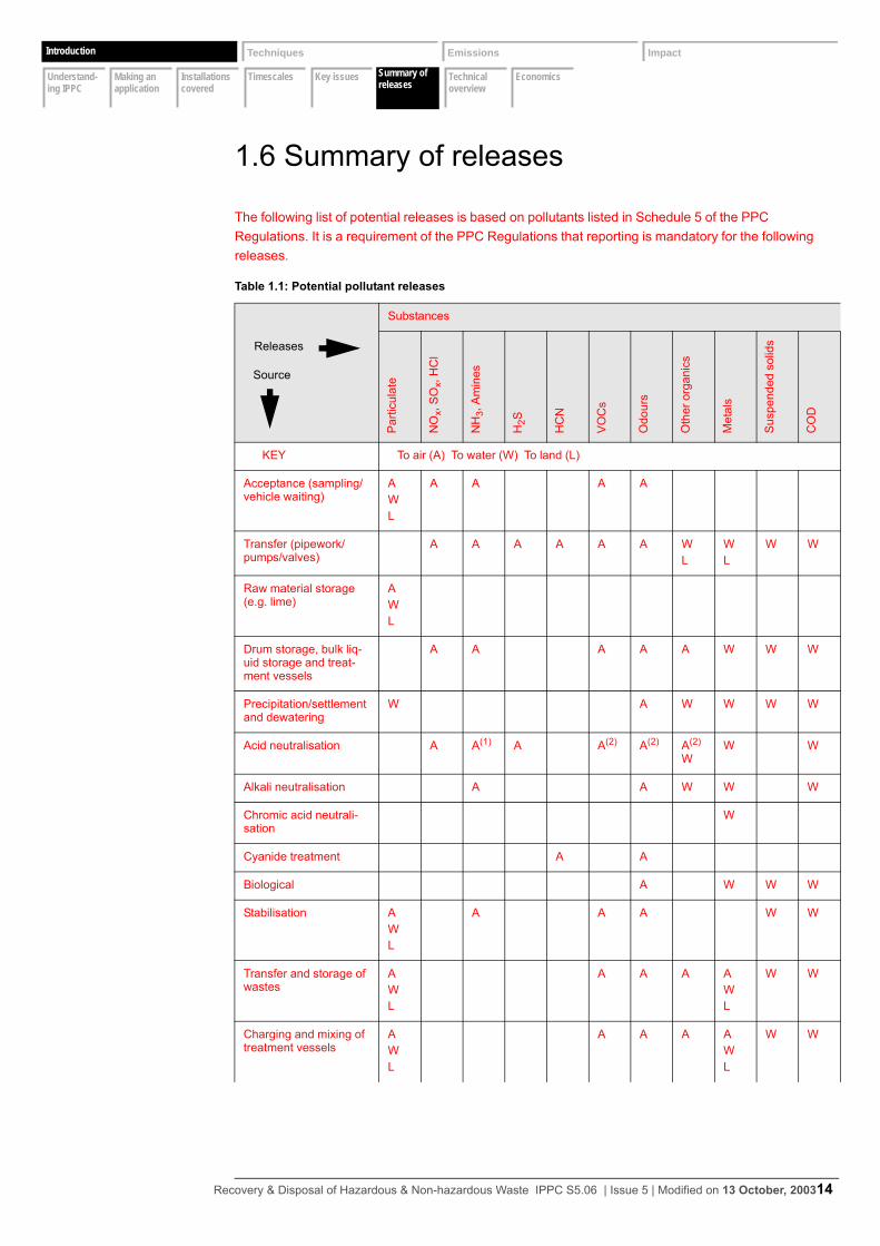
1.6 Summary of releases
The following list of potential releases is based on pollutants listed in Schedule 5 of the PPC Regulations. It is a requirement of the PPC Regulations that reporting is mandatory for the following releases.
Table 1.1: Potential pollutant releases
Substances
Par
ticul
ate
NO
x, S
Ox,
HC
l
NH
3, A
min
es
H2S
HC
N
VO
Cs
Odo
urs
Oth
er o
rgan
ics
Met
als
Sus
pend
ed s
olid
s
CO
D
KEY To air (A) To water (W) To land (L)
Acceptance (sampling/vehicle waiting)
AWL
A A A A
Transfer (pipework/pumps/valves)
A A A A A A WL
WL
W W
Raw material storage (e.g. lime)
AWL
Drum storage, bulk liq-uid storage and treat-ment vessels
A A A A A W W W
Precipitation/settlement and dewatering
W A W W W W
Acid neutralisation A A(1) A A(2) A(2) A(2) W
W W
Alkali neutralisation A A W W W
Chromic acid neutrali-sation
W
Cyanide treatment A A
Biological A W W W
Stabilisation AWL
A A A W W
Transfer and storage of wastes
AWL
A A A AWL
W W
Charging and mixing of treatment vessels
AWL
A A A AWL
W W
Releases
Source
Recovery & Disposal of Hazardous & Non-hazardous Waste IPPC S5.06 | Issue 5 | Modified on 13 October, 200314

Introduction Techniques Emissions Impact
Understand- ing IPPC
Making an application
Installations covered
Timescales Key issues Summary of releases
Technical overview
EconomicsSummary of releases
Introduction
Notes
(1) Specific problem with treatment of sulphuric acid that has been used to scrub an amine release.
(2) Conventional treatment of acidic wastes contaminated with solvents.
Removal of solid resi-due from vessel
AWL
A A A AWL
W w
Oil reprocessing A A A W
Table 1.1: Potential pollutant releases
Substances
Par
ticul
ate
NO
x, S
Ox,
HC
l
NH
3, A
min
es
H2S
HC
N
VO
Cs
Odo
urs
Oth
er o
rgan
ics
Met
als
Sus
pend
ed s
olid
s
CO
D
Releases
Source
Recovery & Disposal of Hazardous & Non-hazardous Waste IPPC S5.06 | Issue 5 | Modified on 13 October, 200315
Introduction Techniques Emissions Impact
Understand- ing IPPC
Making an application
Installations covered
Timescales Key issues Summary of releases
Technical overview
EconomicsTechnical overview
Introduction
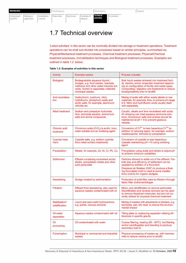
1.7 Technical overview
‘Listed activities’ in this sector can be nominally divided into storage or treatment operations. Treatment operations can be shall sub-divided into processes based on similar principles, summarised as; Physical/Mechanical treatment processes, Chemical treatment processes, Physical/Chemical treatment processes, Immobilisation techniques and Biological treatment processes. Examples are outlined in table 1.2 below;
Table 1.2: Examples of activities in this sector
Activity Example wastes Process includes
Biological Biodegradable aqueous liquids / sludges, e.g. food wastes, leachate, methanol and other water-miscible sol-vents. Sorted or separately collected municipal wastes.
Bulk liquid wastes tankered into treatment facil-ity. Aerobic and/or anaerobic treatment depend-ing on configuration of facility and waste types. Composting / digestion pre-treatments to reduce biodegradability prior to landfill.
Acid neutralisa-tion
Hydrochloric, sulphuric, nitric, hydrofluoric, phosphoric acids and acidic salts, for example, aluminium chloride etc.
Mixing of acids with either waste alkalis or raw materials, for example, lime, to achieve pH range 6-9. Nitric and hydrofluoric acids usually dealt with separately.
Alkali treatment Sodium and potassium hydroxide, lime, ammonia solution, ammonium salts and amine compounds
Caustic, alkalis and lime neutralised with acids. Air stripping can treat aqueous ammonia solu-tions. Ammonium salts and amines should be maintained at pH < 9 to prevent gaseous release.
Chromic acid treatment
Chromium oxide (CrO3) is acidic, toxic, water-soluble and an oxidising agent
Conversion of Cr6+ to less hazardous Cr3+ by addition of reducing agent, for example, sodium metabisulphite, followed by precipitation.
Cyanide treat-ment
Cyanide salts, e.g. sodium cyanide from metal surface treatments
Conversion of cyanide to less hazardous cyanate maintaining pH >10 using oxidising agent
Precipitation Metals, for example, Zn, Ni, Cr, Pb, Cu Precipitation using acids and alkalis to adjust pH to achieve minimum solubilities
Settlement Effluent containing neutralised acids/alkalis, precipitated metals and other solid particulate
Particles allowed to settle out of the effluent. Par-ticle size and efficiency of settlement can be assisted by addition of a flocculentDissolved air flotation (DAF) to produce a float-ing flocculated solid is used at some installa-tions (mainly for organic sludges)
Dewatering Sludge created by sedimentation Production of solid filter cake by filtration through fabric filter cloths/centrifuges
Filtration Effluent from dewatering, also used for aqueous wastes contaminated with oil
Micro- and ultrafiltration to remove particulate. Nanofiltration and reverse osmosis can be used to remove dissolved molecules, but are not cur-rently utilised for physical-chemical treatment
Stabilisation/solidification
Liquid and semi-solid hydrocarbons, e.g. paints, viscous solvents
Mixing of wastes with absorbents or binders, e.g. bentonite, ash, kiln dust, to reduce the environ-mental impact
Oil-water separation
Aqueous wastes contaminated with oil Tilting plate or coalescing separator utilising dif-ferences in specific gravity
Oilprocessing
Oil contaminated with water Coarse filtering, heating (80 - 90oC), hot filtering and/or centrifugation and blending to produce secondary fuel oil
Pulverisation Municipal or commercial and industrial wastes
Physical processing of wastes eg. with hammer-mills to reduce volume prior to landfill
Recovery & Disposal of Hazardous & Non-hazardous Waste IPPC S5.06 | Issue 5 | Modified on 13 October, 200316

Introduction Techniques Emissions Impact
Understand- ing IPPC
Making an application
Installations covered
Timescales Key issues Summary of releases
Technical overview
EconomicsTechnical overview
Introduction
A limited number of issues relating to oil reprocessing are considered. For further details, reference should be made to IPC Guidance Note S2 5.04, Recovery of Organic Solvents and Oil by Distillation.
Recovery & Disposal of Hazardous & Non-hazardous Waste IPPC S5.06 | Issue 5 | Modified on 13 October, 200317
Introduction Techniques Emissions Impact
Understand- ing IPPC
Making an application
Installations covered
Timescales Key issues Summary of releases
Technical overview
EconomicsEconomics
Introduction
1.8 Economics
Waste treatmentIn real terms, treatment charges have fallen over the last 10 years. The average price charged for liquid-phase treatment, e.g. dilute acid neutralisation, dewatering of sludges, has been held between £15 and £35 per tonne. This represents a low financial return, and emphasis has been on optimising turnover through volume. This has been associated with determined competition within the sector, which has contributed to prices being held down. This has also been exacerbated by overcapacity. Another significant factor affecting the economic performance of the treatment sector is that it competes with landfill for a number of waste streams, particularly liquids and drummed wastes. Wastes of this type can still be landfilled for as little as £12/t, despite restraints on capacity and the Landfill Tax. The Landfill Directive will exclude these waste types, removing the low-cost option.
A major operational cost to physico-chemical treatment is the disposal of solid wastes, e.g. filter cakes, and liquid effluents. These require disposal either by landfill or by trade effluent discharge to sewer. Transport and landfilling charges may run to around £30/t for filter cake. Trade effluent charges are also significant and are expected to increase due to the implementation of the Urban Waste Water Treatment Directive.
The industry has generally maximised the constructive use of waste types used to treat other wastes. This is expected to continue, particularly as use of raw materials is a consideration for IPPC. Attention is also being given to utilising techniques such as anaerobic biological treatment to recover and use the methane generated, which is well established by the water companies for sewage sludge.
In general terms investment levels for the treatment sector can be placed in two categories: sites built prior to 1990 and those either developed or refurbished since 1990. Taken as a general observation, investment levels on sites developed prior to 1990 have been low, a situation determined by a reliance on turnover on small margins. For a typical physico-chemical treatment site developed in the 1980s, the level of investment needed to update such a plant is probably in the range of £250k to £750k.
Since 1990 there has been multi-million-pound investment in new sites and investment of up to around the £1 million on process upgrade. These investments have typically been made as additions to a waste business portfolio and not as stand-alone operations.
With very few exceptions, investment in the treatment sector has historically been very low because of the low prices and the competition with landfill. It is expected that high levels of investment will be required to meet the standards set by the new regime.
Restrictions on landfill, which will be introduced by the Landfill Directive and IPPC, will require more treatment of waste either prior to or instead of landfill. This may lead to the continuing development of sites utilising stabilisation and fixation techniques. However, these techniques have been rudimentary and subject to a number of serious problems. The typical level of charge for these processes is around £22/t.
Waste treatment (including oil reprocessing but excluding biological treatment) is typically a high-volume low-return process. A fixed or lowered base price, for either incoming waste or recycled product, has placed the commercial emphasis on maximising throughput and reducing cost overhead.
Consequently prices in general are determined by Operators at the “low” end of the market. With exceptions and also particularly for older plant, investment levels have been low, due to low returns.
Recovery & Disposal of Hazardous & Non-hazardous Waste IPPC S5.06 | Issue 5 | Modified on 13 October, 200318
Introduction Techniques Emissions Impact
Understand- ing IPPC
Making an application
Installations covered
Timescales Key issues Summary of releases
Technical overview
EconomicsEconomics
Introduction
The regulatory conditions are now being put in place to break the cycle of high volume, low return and low investment. There must now be greater investment and a move towards developing techniques to treat wastes that were previously being landfilled directly, or being treated by ineffective processes. These require the development of dedicated plant and equipment for specific wastes, e.g. aqueous ammonia solutions.
Not only will the waste industry need to adapt, but their customer base will no longer be able to rely on a more general non-specific treatment which may amount to little more than dilution. As a consequence, costs are anticipated to rise for waste producers.
Much has already been achieved by waste minimisation initiatives by producers. The regulatory changes are likely to lead to a further impetus to reduce waste and consider options for in-house treatment.
Oil processingOil processing is performed by approximately 75% of commercial used oil installations and the main output is 400,000 tpa recovered fuel oil (RFO). This is widely used as an alternative fuel in the power generating and quarry stone industries. The industry seeks to maintain a high throughput to optimise a low return of the order of a few pence per gallon on the sale of reprocessed oil.
Competition centres between regional reprocessors and national companies. Waste oil is usually collected for a small payment of the order of pence per gallon dependent on the volume of the used oil. National collectors work on large volumes as an economy of scale, while local operators are advantaged by lower cost overheads.
There is also a significant volume of oil-contaminated waters collected for recovery. These wastes have a net negative value and are processed in a manner so as to maximise the recovery of the hydrocarbon for use as a fuel.
The return on reprocessed oil is primarily determined by the price of fuel oil and gas oil, against which reprocessed oil competes. This is balanced against the costs of reprocessing and the requirement to provide an incentive for the collection of waste oil through payment on collection.
Other than transportation, the main operating overhead relates to the generation of steam for heating waste oil. Most sites have on-site boilers for steam production.
The majority of oil reprocessing sites are over 15 years old, and investment in infrastructure and pollution prevention and control measures has been patchy. A contributing factor to this variation has been inconsistent implementation of improvement programmes, either those required by the Regulator or on the initiation of an Operator’s investment programme.
An example of this relating to oil reprocessing is the checking procedures on waste oil feedstock. Typically this involves a basic assessment of the water and solids content for quality and payment purposes.
Improvements have been made, with investment in the order to £50k per site being made in analytical equipment. This has been driven in part by the quality requirements of the users of the reprocessed oil but this is not always a uniform requirement.
The market for RFO may undergo fluctuation as changes occur in its marketing under the classification as a waste. This may be accompanied by changes in the duty derogation on RFO.
Recovery & Disposal of Hazardous & Non-hazardous Waste IPPC S5.06 | Issue 5 | Modified on 13 October, 200319
In-process controls
Emissions controls
Management Raw materials
Waste handling
Waste recovery or disposal
Energy Accidents Noise Monitoring Closure Installation issues
Introduction Techniques Emissions Impact
Economics
Techniques for pollution control
2 Techniques for pollution control
To assist Operators and the Regulator’s officers in respectively making and determining applications for PPC Permits, this section summarises the indicative BAT requirements (i.e. what is considered to represent BAT for a reasonably efficiently operating installation in the sector). The indicative BAT requirements may not always be absolutely relevant or applicable to an individual installation, when taking into account site-specific factors, but will always provide a benchmark against which individual Applications can be assessed.
Summarised indicative BAT requirements are shown in the “BAT boxes”, the heading of each BAT box indicating which BAT issues are being addressed. In addition, the sections immediately prior to the BAT boxes cover the background and detail on which those summary requirements have been based. Together these reflect the requirement s for information laid out in the Regulations, so issues raised in the BAT box or in the introductory section ahead of the BAT box both need to be addressed in any assessment of BAT.
Although referred to as indicative BAT requirements, they also cover the other requirements of the PPC Regulations and those of other Regulations such as the Waste Management Licensing Regulations (see Appendix 2 for equivalent legislation in Scotland and Northern Ireland) and the Groundwater Regulations, insofar as they are relevant to PPC permitting.
For further information on the status of indicative BAT requirements, see Section 1.1 on page 2 of this guidance or Guidance for applicants.
It is intended that all of the requirements identified in the BAT sections, both the explicit ones in the BAT boxes and the less explicit ones in the descriptive sections, should be considered and addressed by the Operator in the Application. Where particular indicative standards are not relevant to the installation in question, a brief explanation should be given and alternative proposals provided. Where the required information is not available, the reason should be discussed with the Regulator before the Application is finalised. Where information is missing from the Application, the Regulator may, by formal notice, require its provision before the Application is determined.
When making an Application, the Operator should address the indicative BAT requirements in this Guidance Note, but also use the Note to provide evidence that the following basic principles of PPC have been addressed:• The possibility of preventing the release of harmful substances by changing materials or processes
(see Section 2.1 on page 22), preventing releases of water altogether (see Section 2.2.2 on page 68), and preventing waste emissions by reuse or recovery, have all been considered, and
• Where prevention is not practicable, that emissions that may cause harm have been reduced and no significant pollution will result.
This approach should assist Applicants to meet the requirements of the Regulations to describe in the Applications techniques and measures to prevent and reduce waste arisings and emissions of substances and heat - including during periods of start-up or shut-down, momentary stoppage, leakage or malfunction.
In responding to the requirements, the Operator should keep the following in mind.• As a first principle, there should be evidence in the application that full consideration has been given
to the possibility of PREVENTING the release of harmful substances, for example, by:– comprehensive characterisation of the wastes (see Section 2.2.1 on page 64 and Section 2.2.2
on page 68)– safe storage (see Section 2.1.3 on page 36)
Recovery & Disposal of Hazardous & Non-hazardous Waste IPPC S5.06 | Issue 5 | Modified on 13 October, 200320

In-process controls
Emissions controls
Management Raw materials
Waste handling
Waste recovery or disposal
Energy Accidents Noise Monitoring Closure Installation issues
Introduction Techniques Emissions Impact
Economics
Techniques for pollution control
– selection of the appropriate treatment technique
Recovery & Disposal of Hazardous & Non-hazardous Waste IPPC S5.06 | Issue 5 | Modified on 13 October, 200321
In-process controls
Emissions controls
Management Raw materials
Waste handling
Waste recovery or disposal
Energy Accidents Noise Monitoring Closure Installation issues
Introduction Techniques Emissions Impact
In-process controls
Techniques for pollution control
2.1 In-process controls
This section covers the key issues of pre-acceptance and acceptance procedures for waste, waste storage, and specific activities for waste treatment.
2.1.1 Pre-acceptance procedures to assess waste
In order to prevent the acceptance of unsuitable wastes which may lead to adverse reactions or uncontrolled emissions, systems and procedures must be in place to ensure that wastes are subject to appropriate technical appraisal. This ensures their suitability for the proposed treatment route. These checks must be carried out before any decision is made to accept a waste.
This requires a system that has, as an initial stage, a screening step or pre-acceptance procedure, involving the provision of information and representative samples of the waste. This will allow Operators to determine the suitability of the waste for the activity before arrangements are in place to accept the waste. The second stage, acceptance procedures when the waste arrives at the site, should serve to confirm the characteristics of the waste, without the time pressure and potential hazard of checking a waste at the gate.
The Operator must obtain the following information:• the nature of the process producing the waste, including the variability of this process• the composition of the waste (chemicals present and individual concentrations)• a representative sample(s) of the waste should be taken from the production process and analysed• for each new waste enquiry the Operator must undertake a comprehensive characterisation of the
waste and identify a suitable treatment method
The information must be recorded and referenced to the waste stream so that it is available at all times. The information must be regularly reviewed and kept up to date with any changes to the waste stream. Waste characterisation must be completed by the Operator unless all necessary information is already available from the producer or current holder of the waste.
The waste producer has obligations under the Duty of Care requirements to provide information on the:• composition of the waste• its handling requirements• its hazards• EWC code
This information is required on transfer of the waste from the producer to another party such as a waste disposal contractor. Experience of this system has shown that reliance cannot be placed solely upon it to provide sufficient information. The producer and operator of the receiving site must ensure that reliable and comprehensive information has been provided to determine the suitability of the waste for the treatment (or recovery) process in question. This also applies if wastes are only to be stored or bulked at the installation so that the information can be provided to the next holder of the waste and the ultimate disposal route identified. The requirement to characterise the waste, including sampling and analysis, equally applies to transfer as well as treatment facilities.
Recovery & Disposal of Hazardous & Non-hazardous Waste IPPC S5.06 | Issue 5 | Modified on 13 October, 200322
In-process controls
Emissions controls
Management Raw materials
Waste handling
Waste recovery or disposal
Energy Accidents Noise Monitoring Closure Installation issues
Introduction Techniques Emissions Impact
In-process controls
Techniques for pollution control
Enquiries from waste producers are commonly routed through a business section of a company, and not directly from the management of the plant producing the waste. Verification of the written information provided by the producer may be required, and this may require a visit to the producer, as additional factors may become apparent when dealing with staff directly involved in the waste production.
It is not unusual for the waste producer and the Operator to be separated by at least one and in some cases three or four different parties. These may be haulage contractors, brokers and waste transfer operators. Where there is a lengthy chain, information may be lost or inaccurately reproduced.
It is an advantage that, as with the provision of information, the number of links in a chain down which a waste sample may be passed is kept to a minimum. This will avoid information loss or misrepresentation.
If not dealing directly with the waste producer, the Operator should carefully verify the information received at the pre-acceptance stage, which, in addition to the minimum Duty of Care information, should include the contact details for the waste producer and a full description of the waste.
There is often reluctance amongst third parties to divulge the identity of the waste producer as this may be of commercial benefit. This however cannot override the fundamental requirement of the Operator, which is to check the information on a waste provided with the waste producer (not just the current holder), who is in the best position to verify the waste.
At the pre-acceptance stage, in addition to written information regarding the waste, the Operator must obtain representative sample(s) of the waste from the production process. Any deviations from this must be fully justified in terms of BAT (see Section 1.1 on page 2).
Adequate sampling and analysis must be carried out to characterise the wastes. In all cases the number of samples taken must be based on an assessment of the risks of potential problems. Sampling regimes at the pre-acceptance stage do not necessarily have to include sampling of every drum, for
example, (where n is the total number of drums) may be acceptable provided acceptance screening includes sampling every container. In some instances physical sampling may not be necessary, for example in the case of gas cylinders or scrap batteries. In other cases such as drummed wastes, large numbers of samples will be necessary as characterisation will require the sampling of all containers. The sampling of process wastes must take account of the variability of the process, and several samples may be required to characterise the waste sufficiently.
As the circumstances of waste production may vary, sound professional judgement is required in ensuring the relevant questions are asked. Operators should ensure that technical appraisal is carried out by suitably qualified and experienced staff who understand the capabilities of the site, independent of sales staff responsible for obtaining the customer’s business. The Environment Agency considers that a minimum qualification of a degree in chemistry (or equivalent) will be required in order to equip staff to carry this assessment out correctly.
This information is necessary to:• screen out unsuitable wastes• confirm the details relating to composition, and identify verification parameters that can be used to
test waste arriving at the site• identify any substances within the waste (for example, by-products) that may affect the treatment
process• identify any substances within the waste that may react with other reagents• accurately define the range of hazards exhibited by the waste• identify any substances within the waste that may be unaffected by the treatment process and
transfer in an unaltered state as a residue in the effluent• determine the cost of the disposal option identified
n 1+
Recovery & Disposal of Hazardous & Non-hazardous Waste IPPC S5.06 | Issue 5 | Modified on 13 October, 200323
In-process controls
Emissions controls
Management Raw materials
Waste handling
Waste recovery or disposal
Energy Accidents Noise Monitoring Closure Installation issues
Introduction Techniques Emissions Impact
In-process controls
Techniques for pollution control
• ensure regulatory compliance, for example, meet COMAH requirements
Using the information on the waste arising, and the sample provided, the Operator should verify the information provided regarding composition and hazard of the waste. Once it has been established that the waste is as described, a treatment method or option for the waste should be determined.
Wastes should not be accepted at the installation without a clear method or defined treatment and disposal route with a full costing. Experience has shown that wastes have been accepted at a site without pre-acceptance checks, on the basis that this would take place at another treatment facility. On examination, the wastes have not only been found to be unsuitable for the site in question, but also due to the composition and hazard have been unsuitable for anything other than incineration. This extra cost has led to wastes being held in an attempt to find alternative disposal routes, which in turn has resulted in some long standing accumulations of wastes, with consequent problems with storage, e.g. leaking drums. These precautions (defined route/treatment method and costings) will need to be in place prior to final acceptance of the waste on-site, not necessarily at the tendering stage, before a contract for disposal has been obtained from the producer.
Pre-acceptance for oil reprocessing:
As a general requirement, this is not as critical as for merchant waste treatment. Typically the waste arisings are from a large number of small-volume sources, eg. garages. Pre-acceptance procedures relating to information collection should be applied for one-off industrial arisings of waste oil and arisings from sources where other chemicals and potential contaminants may be handled, for example, chemical manufacturing.
Contamination by substances such as solvents does occur and, although relatively low levels of contamination can be accommodated by the Operator, insofar as it may not affect the sale of the recovered oil, contamination should be identified. Low-flashpoint solvents will give rise to handling difficulties as the installations are not set up for dealing with flammable materials. Petrol contamination often occurs and this significantly reduces the flashpoint of the material. This will significantly increase the risk of accident. Care should be taken in choosing and interpreting the most appropriate flashpoint determination. Further Guidance is available from HSE (see Ref. 8). Solvents will also be driven off in the heating process, therefore increasing the VOC emissions. Contamination with polychlorinated biphenyls (PCBs) will transfer to either the recovered oil, which may give rise to dioxin formation during subsequent combustion, or the tank bottoms, oil sludges or effluent.
Pre-acceptance packing procedures for “laboratory smalls”:
Laboratory smalls consist of substances in containers of less than 5 litre capacity. They generally contain pure chemical elements and compounds from laboratories or when laboratory stores are cleared. The majority of the Operators offer a packing and collection service for laboratory smalls. A qualified chemist attends the producer’s site, classifying the substances accordingly, and packaging the containers into drums. The individual packages are prevented from mechanical damage in the drum by the use of vermiculite. This classification should be sufficient to enable the Licence Holder to identify each chemical contained within the waste, assess its hazards and identify any particular issues (e.g. water reactivity, flammability) so that wastes which have the potential to react if there is a loss of containment within a drum are packed in different drums, and are not mixed within the same drum.A list of the contents of the drum is created and stored within the drum below the lid. Each packed drum is then labelled with respect to the hazard for carriage. Some Operators only deal with laboratory smalls if the customers use their packing service. The level of supervision or management of this type of situation is dependent on a number of factors, for example, whether the Operator has confidence in the level of understanding required by the customer. In either case a full list of the drum contents should be produced. Operators should have written procedures regarding the segregation and packing of laboratory smalls. For those Operators who accept wastes packaged by their customers, this Guidance should be provided to the customer.
Recovery & Disposal of Hazardous & Non-hazardous Waste IPPC S5.06 | Issue 5 | Modified on 13 October, 200324

In-process controls
Emissions controls
Management Raw materials
Waste handling
Waste recovery or disposal
Energy Accidents Noise Monitoring Closure Installation issues
Introduction Techniques Emissions Impact
In-process controls
Techniques for pollution control
RecordsA waste tracking system should begin at the pre-acceptance stage. With every enquiry a record should be raised (given a unique reference number) which, if the waste disposal enquiry results in waste arriving at site, should “follow” the waste during its acceptance, checking, storage, treatment or removal off-site. If the waste is a regular arising, then the document should be unique to that waste stream. Further details of the requirements of the tracking system are given in Section 2.1.2 on page 28 and Section 2.1.3 on page 36.
All records relating to pre-acceptance should be maintained at the installation for cross-reference and verification at the waste acceptance stage. The length of time records should be held will be determined by whether the waste is actually delivered to the site or likely to be delivered.
Indicative BAT requirements for pre-acceptance (Sheet 1 of 3)
1 From the waste disposal enquiry the Operator should obtain information in writing relating to:• the type of process producing the waste• the specific process from which the waste derives• the quantity of waste;• chemical analysis of the waste (individual constituents and as a minimum their percentage
compositions)• the form the waste takes (solid, liquid, sludge etc)• hazards associated with the waste• sample storage and preservation techniques
2 Unless a sample and analysis has already been completed by a third party and the Operator has sufficient written information from them, then the Operator should in every case obtain representative sample(s) of the waste from the production process/current holder.
3 Other than for pure product chemicals or laboratory smalls, the chemical analysis should relate to an actual analysis and not simply be based on product data sheets or an extrapolation of information on product data sheets. For example, taking the concentrations as specified and applying a dilution factor is not acceptable.
4 Wastes should not be accepted at the installation without a clear method or defined treatment and disposal route being determined and costed before the waste is accepted at the installation.
5 The Operator should ensure that the sample is representative of the waste and obtained by a person who is technically competent to undertake the sampling process.
6 The type of information that would demonstrate the reliability of the sample includes:• location of sampling point, for example, effluent tank• capacity of vessel sampled (for samples from drums an additional parameter would be the
total number of drums)• method of sampling, e.g. sampling tap (mid flow), “top” sample• number of samples and degree of consolidation• operating conditions at time, e.g. normal operation, shut-down, maintenance and/or cleaning• preservation techniques
7 Samples should be clearly labelled and any hazard identified.
8 Sample tracking systems within the installation should be established and be auditable.
9 Analysis should be carried out by a laboratory with robust quality assurance and quality control methods and record keeping.
Recovery & Disposal of Hazardous & Non-hazardous Waste IPPC S5.06 | Issue 5 | Modified on 13 October, 200325
In-process controls
Emissions controls
Management Raw materials
Waste handling
Waste recovery or disposal
Energy Accidents Noise Monitoring Closure Installation issues
Introduction Techniques Emissions Impact
In-process controls
Techniques for pollution control
10 Analysis required will vary depending upon the nature of the waste, the process to be used and what is known about the waste already. Results of analysis should be kept within the tracking system. These details should include:• check on constituents declared by waste producer/holder to ensure Permit compliance,
treatment plant specification and final disposal• all hazardous characteristics• physical appearance• colour• pH• presence, strength and description of odour assessment
11 Further analysis may include other parameters relevant to the treatment method or waste stream eg:• presence of oxidants• acidity and alkalinity• COD• ammonia• flashpoint• presence of sulphide• presence of cyanide• List I and List II substances• other substances of environmental significance
12 Also, for example in the case of oil recovery:• chlorine• sulphur• metals• PCBs
13 Installations accepting waste oil should have the facility to hold and test loads for PCBs or a surrogate test for chlorine at a level of detection to assess compliance with the requirements of the Waste Oils Directive.
14 Following characterisation of the waste, a technical assessment should be made of its suita-bility for treatment and to ensure Permit conditions are being met.
15 There must be a clear distinction between sales and technical staff roles and responsibilities. If non-technical sales staff are involved in waste disposal enquiries, then a final technical assess-ment prior to approval should be made. It is this final technical checking that should be used to avoid build-up of accumulations of wastes.
16 All records relating to pre-acceptance should be maintained at the installation for cross-refer-ence for verification at the waste acceptance stage.
17 For laboratory smalls, whether or not the installation Operator packs them on behalf of the producer, a full list of laboratory smalls should be created and transported with the waste. Operators should have written procedures regarding the segregation, packaging and labelling of laboratory smalls. For those Operators who accept wastes packaged by their customers, this Guidance should be provided to the customer so as to prevent problems when the material is delivered to the installation. This guidance should include the following:• What information is required in order to meet the Licence Holders pre-acceptance checks
Indicative BAT requirements for pre-acceptance (Sheet 2 of 3)
Recovery & Disposal of Hazardous & Non-hazardous Waste IPPC S5.06 | Issue 5 | Modified on 13 October, 200326
In-process controls
Emissions controls
Management Raw materials
Waste handling
Waste recovery or disposal
Energy Accidents Noise Monitoring Closure Installation issues
Introduction Techniques Emissions Impact
In-process controls
Techniques for pollution control
2.1.2 Acceptance procedures when waste arrives at the installation
For waste treatment or transfer, the bulk of the characterisation work should have taken place at the pre-acceptance stage. This means that acceptance procedures when the waste arrives at the site should serve to confirm the characteristics of the waste. This should minimise the time the vehicle delivering the waste is kept waiting.
Measures to deal with acceptable wastes arriving on-site such as a pre-booking system, must be in place to ensure that capacity is available.
With regard to waste oil earmarked for reprocessing, there should be greater emphasis on acceptance procedures than at the pre-acceptance stage.
The issues to be addressed by the Operator in relation to waste acceptance procedures for the installation include the following:• vehicle waiting, load inspection, sampling and offloading areas• traffic control• procedures for checking paperwork arriving with the load• procedures for unloading to allow inspection and sampling• location of designated sampling point(s) (as indicated on site plan)• visual load inspection• drum and package labelling procedures• infrastructure such as bunds and the like (see Section 2.8 on page 97)• sampling procedures for all incoming wastes including bulk (liquid and solid) wastes, wastes in
drums and containers and laboratory smalls• details of sampling of wastes in drums within designated storage, that is, timescale after receipt• verification and compliance testing to confirm identity of the waste, description of the waste• assess consistency with pre-acceptance information and proposed treatment method• rejection criteria• sample retention systems, that is, period of retention• record keeping in relation to producer details, analysis results and treatment methods• procedures for periodic review of pre-acceptance information
• What chemicals are not licensed by the Licence Holders site licence (e.g. radioactive chem-icals, Clinical wastes, explosives,)
• How to identify the waste laboratory chemical• How to establish and record the hazards posed by the chemical• Supporting documentation required (e.g. manufacturers data, material safety data sheets)• Segregation policy for waste laboratory chemicals to avoid mixing of incompatible wastes in
the same drum• How to pack the chemicals• What information is to accompany the waste
Indicative BAT requirements for pre-acceptance (Sheet 3 of 3)
Recovery & Disposal of Hazardous & Non-hazardous Waste IPPC S5.06 | Issue 5 | Modified on 13 October, 200327
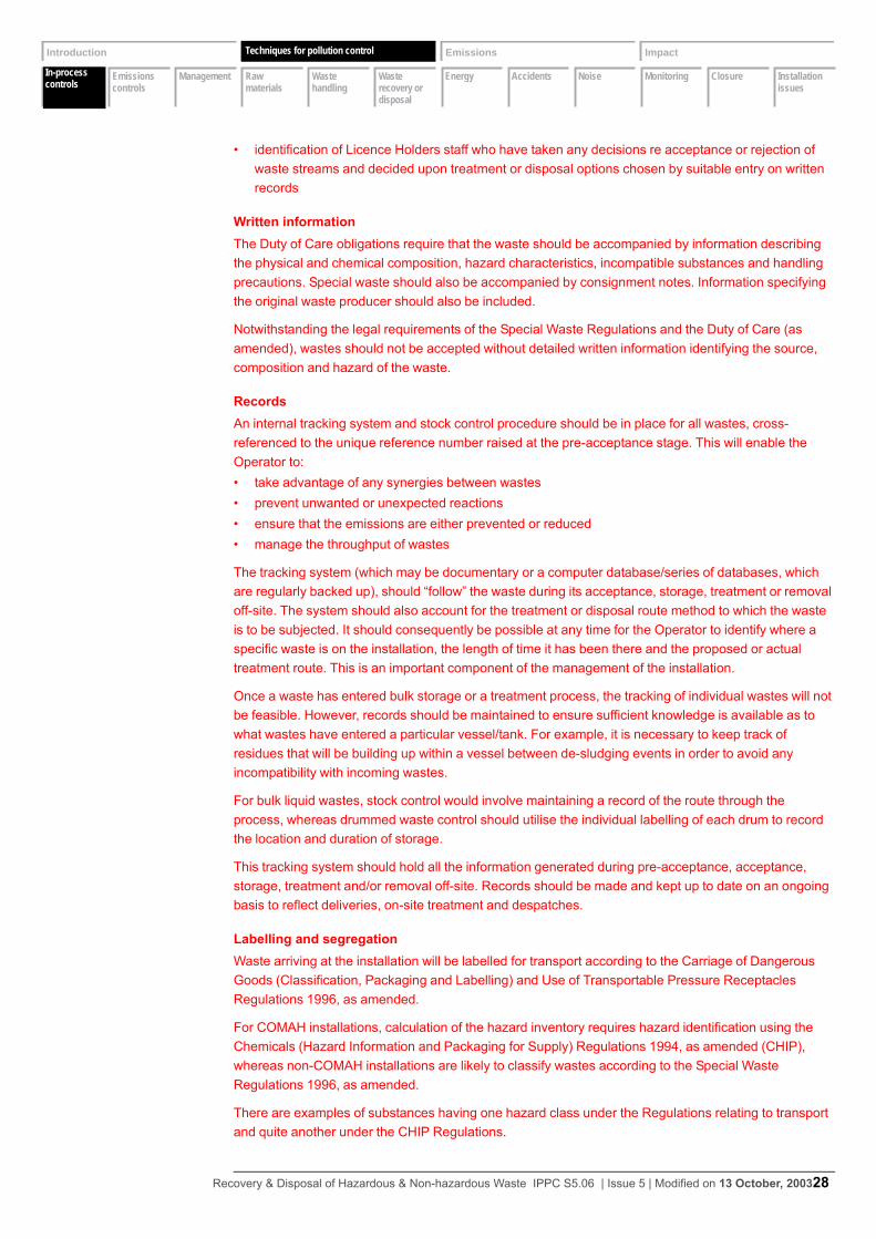
In-process controls
Emissions controls
Management Raw materials
Waste handling
Waste recovery or disposal
Energy Accidents Noise Monitoring Closure Installation issues
Introduction Techniques Emissions Impact
In-process controls
Techniques for pollution control
• identification of Licence Holders staff who have taken any decisions re acceptance or rejection of waste streams and decided upon treatment or disposal options chosen by suitable entry on written records
Written informationThe Duty of Care obligations require that the waste should be accompanied by information describing the physical and chemical composition, hazard characteristics, incompatible substances and handling precautions. Special waste should also be accompanied by consignment notes. Information specifying the original waste producer should also be included.
Notwithstanding the legal requirements of the Special Waste Regulations and the Duty of Care (as amended), wastes should not be accepted without detailed written information identifying the source, composition and hazard of the waste.
RecordsAn internal tracking system and stock control procedure should be in place for all wastes, cross-referenced to the unique reference number raised at the pre-acceptance stage. This will enable the Operator to:• take advantage of any synergies between wastes• prevent unwanted or unexpected reactions• ensure that the emissions are either prevented or reduced• manage the throughput of wastes
The tracking system (which may be documentary or a computer database/series of databases, which are regularly backed up), should “follow” the waste during its acceptance, storage, treatment or removal off-site. The system should also account for the treatment or disposal route method to which the waste is to be subjected. It should consequently be possible at any time for the Operator to identify where a specific waste is on the installation, the length of time it has been there and the proposed or actual treatment route. This is an important component of the management of the installation.
Once a waste has entered bulk storage or a treatment process, the tracking of individual wastes will not be feasible. However, records should be maintained to ensure sufficient knowledge is available as to what wastes have entered a particular vessel/tank. For example, it is necessary to keep track of residues that will be building up within a vessel between de-sludging events in order to avoid any incompatibility with incoming wastes.
For bulk liquid wastes, stock control would involve maintaining a record of the route through the process, whereas drummed waste control should utilise the individual labelling of each drum to record the location and duration of storage.
This tracking system should hold all the information generated during pre-acceptance, acceptance, storage, treatment and/or removal off-site. Records should be made and kept up to date on an ongoing basis to reflect deliveries, on-site treatment and despatches.
Labelling and segregationWaste arriving at the installation will be labelled for transport according to the Carriage of Dangerous Goods (Classification, Packaging and Labelling) and Use of Transportable Pressure Receptacles Regulations 1996, as amended.
For COMAH installations, calculation of the hazard inventory requires hazard identification using the Chemicals (Hazard Information and Packaging for Supply) Regulations 1994, as amended (CHIP), whereas non-COMAH installations are likely to classify wastes according to the Special Waste Regulations 1996, as amended.
There are examples of substances having one hazard class under the Regulations relating to transport and quite another under the CHIP Regulations.
Recovery & Disposal of Hazardous & Non-hazardous Waste IPPC S5.06 | Issue 5 | Modified on 13 October, 200328
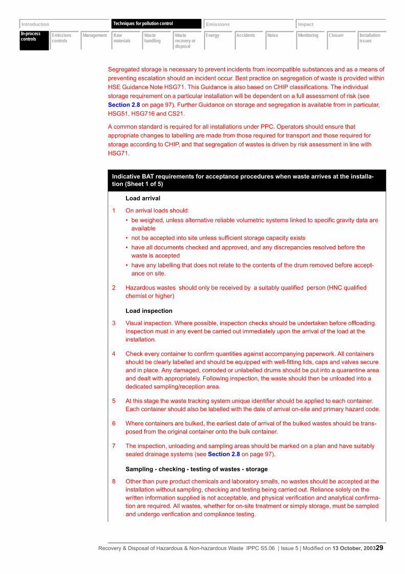
In-process controls
Emissions controls
Management Raw materials
Waste handling
Waste recovery or disposal
Energy Accidents Noise Monitoring Closure Installation issues
Introduction Techniques Emissions Impact
In-process controls
Techniques for pollution control
Segregated storage is necessary to prevent incidents from incompatible substances and as a means of preventing escalation should an incident occur. Best practice on segregation of waste is provided within HSE Guidance Note HSG71. This Guidance is also based on CHIP classifications. The individual storage requirement on a particular installation will be dependent on a full assessment of risk (see Section 2.8 on page 97). Further Guidance on storage and segregation is available from in particular, HSG51, HSG716 and CS21.
A common standard is required for all installations under PPC. Operators should ensure that appropriate changes to labelling are made from those required for transport and those required for storage according to CHIP, and that segregation of wastes is driven by risk assessment in line with HSG71.
Indicative BAT requirements for acceptance procedures when waste arrives at the installa-tion (Sheet 1 of 5)
Load arrival
1 On arrival loads should:• be weighed, unless alternative reliable volumetric systems linked to specific gravity data are
available• not be accepted into site unless sufficient storage capacity exists• have all documents checked and approved, and any discrepancies resolved before the
waste is accepted• have any labelling that does not relate to the contents of the drum removed before accept-
ance on site.
2 Hazardous wastes should only be received by a suitably qualified person (HNC qualified chemist or higher)
Load inspection
3 Visual inspection. Where possible, inspection checks should be undertaken before offloading. Inspection must in any event be carried out immediately upon the arrival of the load at the installation.
4 Check every container to confirm quantities against accompanying paperwork. All containers should be clearly labelled and should be equipped with well-fitting lids, caps and valves secure and in place. Any damaged, corroded or unlabelled drums should be put into a quarantine area and dealt with appropriately. Following inspection, the waste should then be unloaded into a dedicated sampling/reception area.
5 At this stage the waste tracking system unique identifier should be applied to each container. Each container should also be labelled with the date of arrival on-site and primary hazard code.
6 Where containers are bulked, the earliest date of arrival of the bulked wastes should be trans-posed from the original container onto the bulk container.
7 The inspection, unloading and sampling areas should be marked on a plan and have suitably sealed drainage systems (see Section 2.8 on page 97).
Sampling - checking - testing of wastes - storage
8 Other than pure product chemicals and laboratory smalls, no wastes should be accepted at the installation without sampling, checking and testing being carried out. Reliance solely on the written information supplied is not acceptable, and physical verification and analytical confirma-tion are required. All wastes, whether for on-site treatment or simply storage, must be sampled and undergo verification and compliance testing.
Recovery & Disposal of Hazardous & Non-hazardous Waste IPPC S5.06 | Issue 5 | Modified on 13 October, 200329
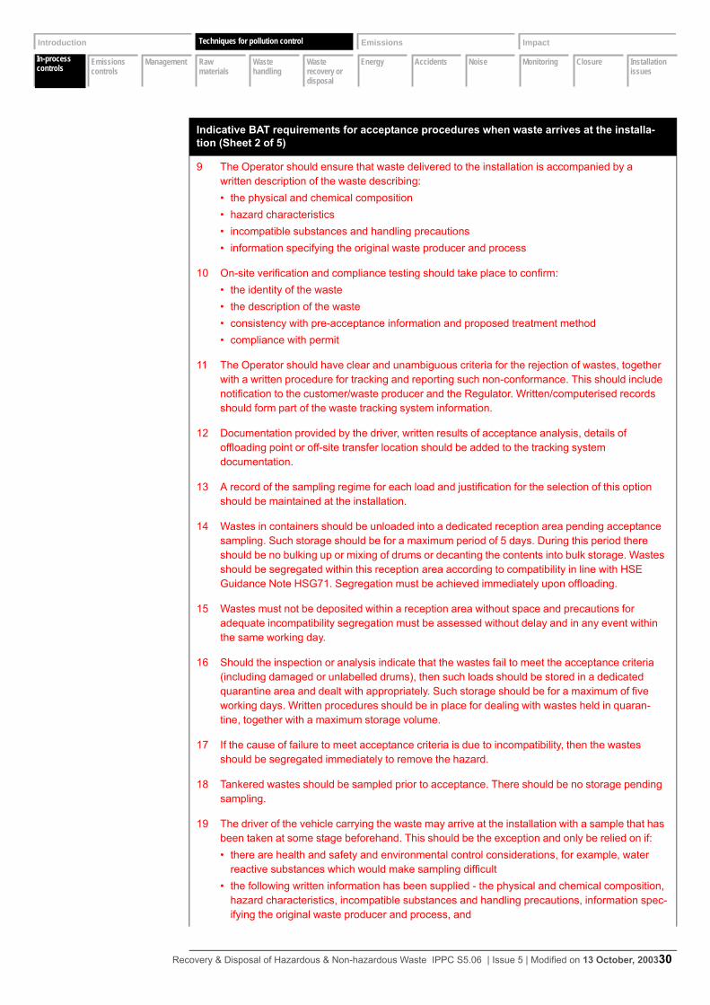
In-process controls
Emissions controls
Management Raw materials
Waste handling
Waste recovery or disposal
Energy Accidents Noise Monitoring Closure Installation issues
Introduction Techniques Emissions Impact
In-process controls
Techniques for pollution control
9 The Operator should ensure that waste delivered to the installation is accompanied by a written description of the waste describing:• the physical and chemical composition• hazard characteristics• incompatible substances and handling precautions• information specifying the original waste producer and process
10 On-site verification and compliance testing should take place to confirm:• the identity of the waste• the description of the waste• consistency with pre-acceptance information and proposed treatment method• compliance with permit
11 The Operator should have clear and unambiguous criteria for the rejection of wastes, together with a written procedure for tracking and reporting such non-conformance. This should include notification to the customer/waste producer and the Regulator. Written/computerised records should form part of the waste tracking system information.
12 Documentation provided by the driver, written results of acceptance analysis, details of offloading point or off-site transfer location should be added to the tracking system documentation.
13 A record of the sampling regime for each load and justification for the selection of this option should be maintained at the installation.
14 Wastes in containers should be unloaded into a dedicated reception area pending acceptance sampling. Such storage should be for a maximum period of 5 days. During this period there should be no bulking up or mixing of drums or decanting the contents into bulk storage. Wastes should be segregated within this reception area according to compatibility in line with HSE Guidance Note HSG71. Segregation must be achieved immediately upon offloading.
15 Wastes must not be deposited within a reception area without space and precautions for adequate incompatibility segregation must be assessed without delay and in any event within the same working day.
16 Should the inspection or analysis indicate that the wastes fail to meet the acceptance criteria (including damaged or unlabelled drums), then such loads should be stored in a dedicated quarantine area and dealt with appropriately. Such storage should be for a maximum of five working days. Written procedures should be in place for dealing with wastes held in quaran-tine, together with a maximum storage volume.
17 If the cause of failure to meet acceptance criteria is due to incompatibility, then the wastes should be segregated immediately to remove the hazard.
18 Tankered wastes should be sampled prior to acceptance. There should be no storage pending sampling.
19 The driver of the vehicle carrying the waste may arrive at the installation with a sample that has been taken at some stage beforehand. This should be the exception and only be relied on if:• there are health and safety and environmental control considerations, for example, water
reactive substances which would make sampling difficult• the following written information has been supplied - the physical and chemical composition,
hazard characteristics, incompatible substances and handling precautions, information spec-ifying the original waste producer and process, and
Indicative BAT requirements for acceptance procedures when waste arrives at the installa-tion (Sheet 2 of 5)
Recovery & Disposal of Hazardous & Non-hazardous Waste IPPC S5.06 | Issue 5 | Modified on 13 October, 200330

In-process controls
Emissions controls
Management Raw materials
Waste handling
Waste recovery or disposal
Energy Accidents Noise Monitoring Closure Installation issues
Introduction Techniques Emissions Impact
In-process controls
Techniques for pollution control
• the waste has been taken directly from the production site to the waste treatment installation
20 The installation should have a designated sampling point or reception area. These should be in close proximity to the laboratory/checking facility and the sampling point should be visible (or covered by CCTV), if sampling is not directly supervised by, for example, laboratory staff.
21 The offloading, sampling point/reception and quarantine areas should have an impervious surface with self-contained drainage, to prevent any spillage entering the storage systems or escaping off-site. Most spills and leaks during sampling are on a small scale, resulting from releases from the back valve of a tanker if the sample is being obtained in this way. Attention should be given to ensuring that incompatible substances do not come into contact resulting from spills from sampling, for example, within a sump serving the sampling point. Absorbents should be made available.
Sampling of bulk liquid wastes
22 Deliveries in bulk road tanker should be accompanied by a “wash-out” certificate or a declara-tion of the previous load so that contamination by this route can be checked.
23 Samples are usually taken by the tanker driver from one of three points on the tanker:• top hatch• back valve• sight glass
24 The key requirement is to obtain a sample that is representative of the load, that is, the sample takes account of the full variation and any partitioning within a bulk load such that “worst-case” scenarios are accounted for. Taking a sample through a top hatch of the surface of the liquid may not be representative, but may be useful in establishing whether there may be a layer of, for example, solvent or some other immiscible substance, which may be unsuitable for treat-ment. Top samples should be obtained from the cross-section of the load, that is, a core sample.
25 A gantry should be constructed to avoid the need to take samples from the back valve of tankers, which is likely to result in a small spillage.
Sampling drummed waste
26 The contents can only be identified with certainty if every container is sampled. Acceptance should involve sampling every container. However, analysis of composite samples is accept-able with such a sampling regime. A representative sample must be obtained by taking a core sample to the base of the container.
27 Operators should ensure that lids, bungs and valves are replaced immediately after sampling.
Drum Labelling• For drummed waste controls should utilise the individual labelling of each drum to record:• the location of each drum• the duration of storage• the chemical identity of the drums contents and• the hazard classification for each drum• Drums should be handled and stored so that the label can be seen at all times.
Indicative BAT requirements for acceptance procedures when waste arrives at the installa-tion (Sheet 3 of 5)
Recovery & Disposal of Hazardous & Non-hazardous Waste IPPC S5.06 | Issue 5 | Modified on 13 October, 200331
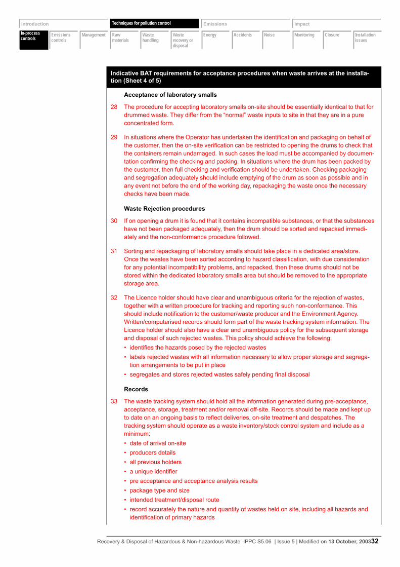
In-process controls
Emissions controls
Management Raw materials
Waste handling
Waste recovery or disposal
Energy Accidents Noise Monitoring Closure Installation issues
Introduction Techniques Emissions Impact
In-process controls
Techniques for pollution control
Acceptance of laboratory smalls
28 The procedure for accepting laboratory smalls on-site should be essentially identical to that for drummed waste. They differ from the “normal” waste inputs to site in that they are in a pure concentrated form.
29 In situations where the Operator has undertaken the identification and packaging on behalf of the customer, then the on-site verification can be restricted to opening the drums to check that the containers remain undamaged. In such cases the load must be accompanied by documen-tation confirming the checking and packing. In situations where the drum has been packed by the customer, then full checking and verification should be undertaken. Checking packaging and segregation adequately should include emptying of the drum as soon as possible and in any event not before the end of the working day, repackaging the waste once the necessary checks have been made.
Waste Rejection procedures
30 If on opening a drum it is found that it contains incompatible substances, or that the substances have not been packaged adequately, then the drum should be sorted and repacked immedi-ately and the non-conformance procedure followed.
31 Sorting and repackaging of laboratory smalls should take place in a dedicated area/store. Once the wastes have been sorted according to hazard classification, with due consideration for any potential incompatibility problems, and repacked, then these drums should not be stored within the dedicated laboratory smalls area but should be removed to the appropriate storage area.
32 The Licence holder should have clear and unambiguous criteria for the rejection of wastes, together with a written procedure for tracking and reporting such non-conformance. This should include notification to the customer/waste producer and the Environment Agency. Written/computerised records should form part of the waste tracking system information. The Licence holder should also have a clear and unambiguous policy for the subsequent storage and disposal of such rejected wastes. This policy should achieve the following:• identifies the hazards posed by the rejected wastes• labels rejected wastes with all information necessary to allow proper storage and segrega-
tion arrangements to be put in place• segregates and stores rejected wastes safely pending final disposal
Records
33 The waste tracking system should hold all the information generated during pre-acceptance, acceptance, storage, treatment and/or removal off-site. Records should be made and kept up to date on an ongoing basis to reflect deliveries, on-site treatment and despatches. The tracking system should operate as a waste inventory/stock control system and include as a minimum:• date of arrival on-site• producers details• all previous holders• a unique identifier• pre acceptance and acceptance analysis results• package type and size• intended treatment/disposal route• record accurately the nature and quantity of wastes held on site, including all hazards and
identification of primary hazards
Indicative BAT requirements for acceptance procedures when waste arrives at the installa-tion (Sheet 4 of 5)
Recovery & Disposal of Hazardous & Non-hazardous Waste IPPC S5.06 | Issue 5 | Modified on 13 October, 200332
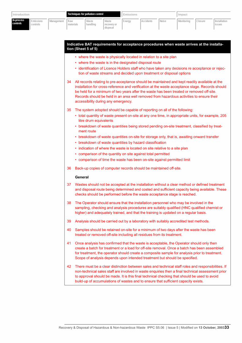
In-process controls
Emissions controls
Management Raw materials
Waste handling
Waste recovery or disposal
Energy Accidents Noise Monitoring Closure Installation issues
Introduction Techniques Emissions Impact
In-process controls
Techniques for pollution control
• where the waste is physically located in relation to a site plan• where the waste is in the designated disposal route• identification of Licence Holders staff who have taken any decisions re acceptance or rejec-
tion of waste streams and decided upon treatment or disposal options
34 All records relating to pre-acceptance should be maintained and kept readily available at the installation for cross-reference and verification at the waste acceptance stage. Records should be held for a minimum of two years after the waste has been treated or removed off-site. Records should be held in an area well removed from hazardous activities to ensure their accessibility during any emergency.
35 The system adopted should be capable of reporting on all of the following:• total quantity of waste present on-site at any one time, in appropriate units, for example, 205
litre drum equivalents• breakdown of waste quantities being stored pending on-site treatment, classified by treat-
ment route• breakdown of waste quantities on-site for storage only, that is, awaiting onward transfer• breakdown of waste quantities by hazard classification• indication of where the waste is located on site relative to a site plan• comparison of the quantity on site against total permitted• comparison of time the waste has been on-site against permitted limit
36 Back-up copies of computer records should be maintained off-site.
General
37 Wastes should not be accepted at the installation without a clear method or defined treatment and disposal route being determined and costed and sufficient capacity being available. These checks should be performed before the waste acceptance stage is reached.
38 The Operator should ensure that the installation personnel who may be involved in the sampling, checking and analysis procedures are suitably qualified (HNC qualified chemist or higher) and adequately trained, and that the training is updated on a regular basis.
39 Analysis should be carried out by a laboratory with suitably accredited test methods.
40 Samples should be retained on-site for a minimum of two days after the waste has been treated or removed off-site including all residues from its treatment.
41 Once analysis has confirmed that the waste is acceptable, the Operator should only then create a batch for treatment or a load for off-site removal. Once a batch has been assembled for treatment, the operator should create a composite sample for analysis prior to treatment. Scope of analysis depends upon intended treatment but should be specified.
42 There must be a clear distinction between sales and technical staff roles and responsibilities. If non-technical sales staff are involved in waste enquiries then a final technical assessment prior to approval should be made. It is this final technical checking that should be used to avoid build-up of accumulations of wastes and to ensure that sufficient capacity exists.
Indicative BAT requirements for acceptance procedures when waste arrives at the installa-tion (Sheet 5 of 5)
Recovery & Disposal of Hazardous & Non-hazardous Waste IPPC S5.06 | Issue 5 | Modified on 13 October, 200333
In-process controls
Emissions controls
Management Raw materials
Waste handling
Waste recovery or disposal
Energy Accidents Noise Monitoring Closure Installation issues
Introduction Techniques Emissions Impact
In-process controls
Techniques for pollution control
2.1.3 Waste storage
The key issues for the Operator to address in relation to measures for waste storage on the installation will include the following:• location of storage areas• storage area infrastructure• condition of tanks, drums, vessels and other containers• stock control• segregated storage• site security
Once it has been determined that the waste is suitable for the installation, the Operator should have in place systems and procedures to ensure that wastes are transferred to appropriate storage safely.
Segregated storage is necessary to prevent incidents from incompatible substances and as a means of preventing escalation should an incident occur. The individual storage requirement on a particular installation will be dependent on a full assessment of risk (see Section 2.8 on page 88). Further Guidance on storage and segregation is available from HSE, in particular, HSG51, HSG71 and HSG716.
Waste Tracking (Audit) SystemsThe waste tracking system begun at the pre-acceptance stage, linked with acceptance should continue throughout the duration of time that the waste is kept at the site. The system adopted should meet the objectives and standards given in Section 2.1.2 on page 28.
Once a waste has entered bulk storage or a treatment process, the tracking of individual wastes will not be feasible. However, records should be maintained to ensure sufficient knowledge is available as to what wastes have entered a particular vessel/tank. For example, it is necessary to keep track of residues that will be building up within a vessel between desludging events in order to avoid any incompatibility with incoming wastes.
For bulk liquid wastes, stock control would involve maintaining a record of the route through the process. For drummed waste, stock control should utilise the individual labelling of each drum to record the location and duration of storage together with the chemical identity and composition of the drums contents and the hazards posed by these contents.
Waste StorageSegregated storage and the use of appropriate separation distances and or suitable engineering measures between incompatible wastes is necessary to prevent incidents from incompatible substances and as a means of preventing escalation should an incident occur. Health and safety guidance on storage and segregation is available from HSE, in particular HSG51& HSG71 (Ref.21) and the measures set out in these documents do afford some degree of environmental protection. However, as already pointed out, waste poses additional hazards over and above those addressed in HSG51 & HSG71 and other activities (e.g. bulking up of waste solvents, storage of pesticides, storage of aerosols and clinical wastes) are not addressed in these documents.
The individual storage requirements on a particular facility will therefore be dependent on a full, site-specific assessment of risk. If operating an existing facility this risk assessment will help Licence Holders decide the quantities or types of materials which can be stored so as not to impose a significant risk on the neighbouring population or ecosystems. Sites in sensitive locations (e.g. close to housing, controlled waters etc) may be required to restrict the waste held on site (either in terms of quantity, type or both) so as to control risks to an acceptable level.
Recovery & Disposal of Hazardous & Non-hazardous Waste IPPC S5.06 | Issue 5 | Modified on 13 October, 200334
In-process controls
Emissions controls
Management Raw materials
Waste handling
Waste recovery or disposal
Energy Accidents Noise Monitoring Closure Installation issues
Introduction Techniques Emissions Impact
In-process controls
Techniques for pollution control
Emergency StorageIn addition to the normal operational requirements, consideration should be given to the provision of emergency storage capacity. This would be relevant to a situation where it would be necessary to transfer a waste from a vehicle, due to a defect or potential failure of the vehicle containment. These events are infrequent, and available capacity within the installation may be a limiting factor. Similarly the Operator should specify procedures for circumstances where vehicles carrying waste are to be parked on-site overnight or on Bank Holidays, when the site may be unsupervised over these periods.
Indicative BAT requirements for waste storage (Sheet 1 of 6)
Offloading/discharge of waste
1 The Operator should have in place a system to ensure that the correct discharge point or storage area is used. The options for this include:• ticket systems• supervision by site staff and if relevant CCTV• keys• colour-coded points/hoses or fittings of a specific size
2 Offloading and quarantine points should have an impervious surface with self-contained drainage, to prevent any spillage entering the storage systems or escaping off-site (see Section 2.8 on page 97).
3 Damaged hoses and connections must not be used.
4 Only couplings of the correct size for the connection should be used and the coupling should be able to withstand the maximum shut valve pressure of the transfer pump.
Record keeping
5 The Operator should have an internal tracking system which should satisfy the objectives and minimum standards given at Section 2.1.2 on page 28 for all wastes.
General storage requirements
6 Storage areas are often the most visible aspects of the installation. Storage areas should be located away from watercourses and sensitive perimeters, for example, those which may be adjacent to public rights of way, housing or schools, and within the security-protected area of the installation to prevent vandalism.
7 Storage areas should be located to eliminate or minimise the double handling of wastes within the installation.
8 Storage areas should be clearly marked and signed with regard to the quantity and hazardous characteristics of the wastes stored therein.
9 The total maximum storage capacity of the site should be clearly and unambiguously stated in writing, accompanied with details of the method used to calculate the volumes held against this maximum. The stated maximum capacity of storage areas should not be exceeded.
10 All containers should be clearly labelled with the date of arrival, relevant hazard code(s), chemical identity and composition of the waste and a reference number or code enabling iden-tification through stock control and cross-reference to pre-acceptance and acceptance records. All labelling should be resilient enough to stay attached and legible throughout the whole time of storage at the installation.
11 Storage area drainage infrastructure should ensure that all contaminated run-off is contained and that drainage from incompatible wastes cannot come into contact with each other.
Recovery & Disposal of Hazardous & Non-hazardous Waste IPPC S5.06 | Issue 5 | Modified on 13 October, 200335
In-process controls
Emissions controls
Management Raw materials
Waste handling
Waste recovery or disposal
Energy Accidents Noise Monitoring Closure Installation issues
Introduction Techniques Emissions Impact
In-process controls
Techniques for pollution control
12 Procedures must be in place for the regular inspection and maintenance of storage areas, including drums, vessels, pavements and bunds. Inspections should pay particular attention to signs of damage, deterioration and leakage. Records should be kept detailing action taken. Faults must be repaired as soon as practicable. If containment capacity or capability of bund, sump or pavement is compromised, then waste must be immediately removed until the repair is completed.
13 There should be daily inspection of the condition of containers and pallets and written records should be kept of these inspections. If a container is found to be damaged, leaking or in a state of deterioration, it should immediately be over-drummed or the contents to transferred to another container.
14 Over-drumming should be seen as an emergency measure and take place, if appropriate, in a designated location equipped with Local Exhaust Ventilation (LEV) as necessary. All appro-priate information should be transferred onto the label of the new container. Large quantities of wastes in over-drums should be avoided by re-drumming once the incident leading to over-drumming has been dealt with. Pallets damaged to the extent that the stability of the containers is or may become compromised should be replaced. “Plastic shrink wrap” should only be used to provide secondary stability to drum/container storage in addition to the use of sound pallets.
15 There should be vehicular, for example, forklift, and pedestrian access at all times to the whole of the storage area such that the transfer of containers is not reliant on the removal of others that may be blocking access, other than drums in the same row. Drums should not be stored more than two high and allow access for inspection on all sides. That is, four x 205 litre drums on a pallet, stacked no more than two x 205 litre drums high in rows.
16 All spillages of hazardous wastes should be logged, where spillages >200 litre then addition-ally the Regulator should be informed.
Turnover
17 Storage within the reception area should be for a maximum of five working days. Following receipt, wastes should be treated or removed off-site as soon as possible. The total storage time will depend upon the characteristics of a particular site and the waste types being stored. For example, on a site in a sensitive location handling hazardous wastes, it may be appro-priate to limit storage times to one month. Other non-hazardous wastes, however, may be held on-site for longer periods. However, all waste should be treated or removed off site within a maximum of six months from the date of receipt.
Storage of drummed waste and other containerised wastes such as IBCs
18 Storage under cover for drummed waste has the advantage of reducing the amount of poten-tially contaminated water that may be produced in the event of any spillage and extending the useful life of the container. It is preferable that wastes are stored under cover. This should also apply to any container that is held in storage pending sampling and emptied containers. Covered areas must have adequate provision for ventilation by means of wall or roof vents or construction of the area, for example, open barn. Any such warehousing should meet the requirements of HSG71.
19 Containers should be stored in such a manner that leaks and spillages could not escape over bunds/edge of the sealed drainage area.
20 Containers should be stored with well-fitting lids, caps and valves, secure and in place.
21 Storage areas for containers holding substances that are known to be sensitive to heat and light or reactive with water or moisture should be under cover and protected from water, heat and direct sunlight.
Indicative BAT requirements for waste storage (Sheet 2 of 6)
Recovery & Disposal of Hazardous & Non-hazardous Waste IPPC S5.06 | Issue 5 | Modified on 13 October, 200336

In-process controls
Emissions controls
Management Raw materials
Waste handling
Waste recovery or disposal
Energy Accidents Noise Monitoring Closure Installation issues
Introduction Techniques Emissions Impact
In-process controls
Techniques for pollution control
22 Storage areas for containers holding flammable or highly flammable wastes should meet the requirements of HSG 51, HSG71 and HSG176.
Aged stock
23 It is important to avoid accumulations of waste, which may in turn lead to a deterioration in the container resulting in spillage or, in extreme cases, the deformation of the container to such an extent that it cannot be moved.
Segregation
24 In addition to the requirements of this document, the segregation of wastes should meet the requirements of HSG71 and be justified by risk assessment.
Storage of laboratory smalls
25 Written procedures for the segregation and packing of laboratory smalls should be produced identifying;• How the hazards associated with each package are identified.• How the risks of adverse reactions occurring between individual packages are assessed,
and by whom.• The level of competence, qualification and training required by those undertaking this
assessment• How incompatible substances (i.e. those that could react to generate heat, fire or hazardous
reaction products) are prevented from being stored within the same drum.• How the wastes are to be stored• How the wastes are to be disposed of• Incompatible substances should not be stored within the same drum.
26 Sorting and repackaging of laboratory smalls should take place in a dedicated area/store. Once the wastes have been sorted according to hazard classification, with due consideration for any potential incompatibility problems, and repacked, then these drums should not be stored within the dedicated laboratory smalls area but should be removed to the appropriate storage area.
Compatibility testing
27 In order to prevent any adverse or unexpected reactions and releases before transfer involving the following activities, testing should take place prior to the transfer:• tanker discharge to bulk storage• tank-to-tank transfer• transfer from container to bulk tank• bulking into drums/IBCs• bulking of solid waste into drums or skips
28 Any evolved gases and cause of odour should be identified. If any adverse reaction is observed, an alternative discharge or disposal route should be found.
29 Due consideration should be taken of the implications of scale-up from laboratory compatibility testing to bulk transfer and the Guidance is given in HSG143.
Indicative BAT requirements for waste storage (Sheet 3 of 6)
Recovery & Disposal of Hazardous & Non-hazardous Waste IPPC S5.06 | Issue 5 | Modified on 13 October, 200337

In-process controls
Emissions controls
Management Raw materials
Waste handling
Waste recovery or disposal
Energy Accidents Noise Monitoring Closure Installation issues
Introduction Techniques Emissions Impact
In-process controls
Techniques for pollution control
Transfer from tanker, drums and other containers in bulk storage
30 Wastes in containers should be transferred into storage vessels by dip pipe to minimise splash, fume and odour.
31 Transfer/discharge should only take place after compatibility testing has been completed and then only with the sanction of an appropriate manager. Approval should specify which batch/load of material is to be transferred, the receiving storage vessel, equipment required, including spillage control and recovery equipment, and any special provisions relevant to that batch/load
32 During bulking to tankers, vapour balance lines connected to appropriate abatement equip-ment should be used.
33 Tankers must not be used as reaction vessels. Blending by bulking into tankers should only take place following a risk assessment and once suitable verification and compatibility testing has been carried out.
34 If flammable chemicals are being transferred, particular caution has to be taken to avoid the generation of static electricity, with the subsequent risk of ignition. Guidance on the safe use and handling of flammable liquids is provided by the Health and Safety Executive and is contained within HSG140, including Guidance on the issue of static electricity build-up.
35 A representative sample of the receiving tank/vessel/container should be mixed in a propor-tional ratio with a sample of incoming waste stream that it is proposed to add to the tank/vessel/container. The two samples should take account of the “worst-case” scenario of likely constituents. The particular test parameters will be driven by the wastes being bulked. As a minimum, records of testing should be kept including any reaction giving rise to:• increase in temperature• viscosity change• separation or precipitation of solids• evolution of gases• evolution of odours
Bulking up into drums (includes drum, tank, tanker or small container transfers into drums)
36 Bulking/mixing should only take place under instruction from and under direct supervision of a suitable manager/chemist and should be under Local Exhaust Ventilation (LEV) in appropriate cases. Odorous materials should not be bulked up. If bulking different batches, then a composite sample must be compatibility tested prior to bulking.
37 Containers should be kept lidded/sealed as much as possible. If transfer involves tanker to drum, a minimum of two people should be checking pipes and valves at all times.
Bulking of solid waste
38 Bulking of different batches must not take place without compatibility testing. In appropriate cases, LEV should be used to control odour and dust. Drums should be manipulated using mechanical means, for example, forklift with rotating drum handling fitting. Liquid waste must not be added to solid wastes other than in purpose-designed and -built reaction vessel, that is, decanting of liquids into a skip containing bulked solids must not take place.
Indicative BAT requirements for waste storage (Sheet 4 of 6)
Recovery & Disposal of Hazardous & Non-hazardous Waste IPPC S5.06 | Issue 5 | Modified on 13 October, 200338
In-process controls
Emissions controls
Management Raw materials
Waste handling
Waste recovery or disposal
Energy Accidents Noise Monitoring Closure Installation issues
Introduction Techniques Emissions Impact
In-process controls
Techniques for pollution control
Bulk storage vessels
39 Bulk storage vessels should be located on an impervious surface that is resistant to material being stored with sealed construction joints within a bunded area with a capacity at least 110% of the largest vessel.
40 Vessels supporting structures, pipes, hoses and connections should be resistant to the substances (and mix of substances) being stored. There should be a routine programmed inspection of tanks, mixing and reaction vessels including periodic thickness testing. In the event of damage or deterioration being detected, the contents should be transferred to appro-priate storage. These inspections should preferably be carried out by independent expert staff, and written records should be maintained of the inspection and any remedial action taken.
41 Vessels should not be used beyond the specified design life, unless verified and inspected at regular intervals, with written records kept to prove that they remain fit for purpose.
42 No open-topped tanks, vessels or pits should be used for storage of hazardous or liquid wastes
43 No uncontrolled venting to atmosphere should be allowed, and all vents should be linked to suitable scrubbing and abatement systems. Vapour balance lines should be connected to suitable abatement systems.
44 Tank and vessel optimum design should be considered in each case, taking into account waste type, storage time, overall tank design and mixing system to prevent sludge accumulation and to ease desludging. Storage and treatment vessels should be regularly desludged.
45 Tanks and vessels should be equipped with suitable abatement systems, level meters with audible and visual high-level alarms. These systems should be sufficiently robust and regu-larly maintained to prevent foaming and sludge build-up affecting the reliability of the gauges.
46 Storage vessels holding flammable or highly flammable wastes should meet the requirements of HSG51, HSG140, HSG716 and HSG176.
47 All connections between vessels must be capable of being closed via suitable valves. Overflow pipes should be directed to a contained drainage system, which may be the relevant bunded area, or to another vessel provided suitable control measures are in place.
48 Underground or partially underground vessels without secondary containment, for example, double-skinned vessels with leakage detection, should be scheduled for replacement by above-ground structures. In any event all such structures without secondary containment should be replaced within one year from the date of issue of the Permit.
49 Plant and equipment taken out of use should be decontaminated and removed.
50 Pipework should preferably be routed above ground; if below ground it should be contained within suitable inspection channels.
51 Silos should be equipped with abatement systems, level monitors and high-level alarms.
52 Storage bunkers should have extraction systems for particulate abatement or spray damping.
Tank & process pipework labelling
53 All vessels should be clearly signed as to their contents and capacity and should have a unique identifier. Tanks should be appropriately labelled.
54 Labelling should differentiate between wastewater and process water, combustible liquid and combustible vapour and direction of flow.
Indicative BAT requirements for waste storage (Sheet 5 of 6)
Recovery & Disposal of Hazardous & Non-hazardous Waste IPPC S5.06 | Issue 5 | Modified on 13 October, 200339

In-process controls
Emissions controls
Management Raw materials
Waste handling
Waste recovery or disposal
Energy Accidents Noise Monitoring Closure Installation issues
Introduction Techniques Emissions Impact
In-process controls
Techniques for pollution control
2.1.4 Treatment - general principles
Treatment involves a change or modification of the characteristics of a substance to make it suitable for another means of disposal. The properties that are manipulated during treatment include: • solubility• acidity, alkalinity• toxicity• separation of phases
These treatment processes may involve displacement and transfer of substances between media resulting in a liquid effluent sent to sewer and a solid residue sent to landfill. Alternatively the waste may be rendered suitable for another treatment route such as combustion of recovered fuel oil.
There are also a number of important ancillary activities associated with treatment such as waste acceptance and storage either pending treatment on-site or removal off-site.
The key issues for the Operator in relation to measures for the treatment of waste on the installation will include the following:• ensuring that the waste is suitable for the activity (pre-acceptance)• adequately characterising the waste (acceptance procedures)• appropriate and safe storage of wastes (storage)• provision and maintenance of suitable infrastructure• operational control of the treatment process• disposal of effluents
55 Written records of all tanks should be kept detailing:• unique identifier• capacity• construction including materials• maintenance schedules and inspection results• fittings• waste types that may be stored/treated in the vessel including flashpoint limit
56 A suitable pipework coding system should be used, for example, RAL European standard colour coding.
57 All valves should be tagged with a unique identifier shown on the process and instrumentation diagram. All connections should be correctly sized and maintained in an undamaged state.
Other storage requirements
58 Waste or raw materials in non-waterproof packaging should be kept under cover.
Container movement
59 Drums and other mobile containers should only be moved between different locations (or loaded for removal off-site) in accordance with written procedures. The waste tracking system should then be amended to record these changes.
Indicative BAT requirements for waste storage (Sheet 6 of 6)
Recovery & Disposal of Hazardous & Non-hazardous Waste IPPC S5.06 | Issue 5 | Modified on 13 October, 200340
In-process controls
Emissions controls
Management Raw materials
Waste handling
Waste recovery or disposal
Energy Accidents Noise Monitoring Closure Installation issues
Introduction Techniques Emissions Impact
In-process controls
Techniques for pollution control
The Applicant must first identify the waste types to be subject to each process, including all contaminants. The chemistry of the process and the fate of all the waste components and any reaction products should be identified. Where components that may be harmful to the environment are not destroyed but are displaced from one medium to another, suitable recovery or abatement must be in place to prevent pollution.
The treatment option must provide an environmentally acceptable method, and must be demonstrated to provide BAT for each waste type.
There are three fundamental ways of achieving this:• adequately characterising the waste• ensuring that the waste is suitable for the activity• ensuring operational control of the treatment process including inputs, reaction monitoring and hav-
ing clear end-point objectives
In order to prevent the direct transfer of pollutants, it would therefore follow that substances capable of pollution that may be released from the process and are neither changed nor modified should not be subject to treatment processes. Displacement is only acceptable if recovery and/or abatement systems are in place. The options are determined by choosing between the types of waste to be handled and the level of plant and equipment utilised. Displacement and/or production of polluting substances must be balanced by recovery or abatement.
Monitoring of the reaction is necessary because the reaction characteristics in the reactor may vary from those in the laboratory test. Monitoring should provide early indication of any deviation from the laboratory test, which should enable measures to be taken to halt or modify the reaction. There should consequently be provision for cooling and/or quenching of reactor vessels.
The success of the reaction will depend on whether there is adequate mixing within a treatment vessel. The standard method for agitating the contents of a vessel is a rotating impeller. There is a geometric ratio between size of impeller and clearance from vessel (determined by type and size of vessel). This is also dependent on agitation speed and the characteristics of the waste. A seal is required where the impeller enters the vessel to prevent fugitive releases. A method of mixing should be provided.
Indicative BAT requirements for treatment - general principles (Sheet 1 of 5)
General principles
1 Provide adequate process descriptions of the activities and the abatement and control equip-ment for all of the activities such that the Regulator can understand the process in sufficient detail to assess the operator’s proposals and in particular to be able to assess opportunities for further improvements. This should include:• diagrams of the main plant items where they have environmental relevance, for example,
storage, tanks, treatment and abatement plant design, etc.• details of chemical reactions and their reaction kinetics/energy balance• equipment inventory, detailing plant type and design parameters, for example, flashpoints• waste types to be subjected to the process• control system philosophy and how the control system incorporates environmental monitor-
ing information• process flow diagrams (schematics)• venting and emergency relief provisions• summary of operating and maintenance procedures• a description of how protection is provided during abnormal operating conditions such as,
runaway reactions, unexpected releases, start-up, momentary stoppages and shut-down for as long as is necessary to ensure compliance with release limits in Permits
Recovery & Disposal of Hazardous & Non-hazardous Waste IPPC S5.06 | Issue 5 | Modified on 13 October, 200341
In-process controls
Emissions controls
Management Raw materials
Waste handling
Waste recovery or disposal
Energy Accidents Noise Monitoring Closure Installation issues
Introduction Techniques Emissions Impact
In-process controls
Techniques for pollution control
• additionally, for some applications, it may be appropriate to supply process instrumentation diagrams for systems containing potentially polluting substances
2 Provide an assessment of the efficiency of the treatment process in relation to Schedule 5 (Ref. 2) pollutants in terms of the removal or partition of substances within the process, for example:• the precipitation of metals from solution for removal in the filter cake• the degree of transfer between the incoming waste and the emissions (to air, solid waste to
land and liquid effluent to sewer of, for example, pesticides or solvents)
3 The Operator should analyse these parameters using the following steps:• process mapping - identify the pathways within the process for the specific substance or sub-
stances• mass balance• action plan - if the study indicates that losses from a process are contributing to:• the breach of an Environmental Quality Standard• the breach of benchmark• a significant environmental impact
then an action plan should be prepared and implemented.
4 If there is uncertainty, the degree of detail required should be established in pre-application discussions.
5 The control of a treatment process is crucial to environmental protection and accident prevention.
6 For each treatment process, the objectives and reaction chemistry should be clearly defined. There must be a defined end-point to the process so that the reaction can be monitored and controlled. The suitable inputs to the process must be defined, and the design must take into account the likely variables expected within the waste stream.
7 Each new reaction, proposed mixes of wastes and reagents should be assessed prior to treat-ment in a scale laboratory test mix of the wastes and reagents to be used. This should lead to all reactions and mixing of wastes being to a predetermined batch “recipe”. It should also take into account the potential scale-up effects, for example, increased heat of reaction with increased reaction mass relative to the reactor volume, increased residence time within the reactor and modified reaction properties. See HSG143 for further Guidance.
8 The reactor vessel and plant should be specifically designed, commissioned and operated to be fit for purpose. Such designs should include consideration of chemical process hazards and a hazard assessment of the chemical reactions, prevention and protective measures together with consideration of process management i.e. working instructions, staff training, plant main-tenance, checks, audits and emergency procedures.
9 In order to track and control the process of change, there should be a written procedure for proposal, consideration and approval of changes to technical developments, procedural or quality changes.
10 All treatment/reaction vessels should be enclosed and should be vented to atmosphere via an appropriate scrubbing and abatement system (subject to explosion relief).
Indicative BAT requirements for treatment - general principles (Sheet 2 of 5)
Recovery & Disposal of Hazardous & Non-hazardous Waste IPPC S5.06 | Issue 5 | Modified on 13 October, 200342
In-process controls
Emissions controls
Management Raw materials
Waste handling
Waste recovery or disposal
Energy Accidents Noise Monitoring Closure Installation issues
Introduction Techniques Emissions Impact
In-process controls
Techniques for pollution control
11 Where appropriate, reactor vessels (or mixing vessels where the treatment is carried out) should be charged with pre-mixed wastes and reagents. For example, reactor vessels should be “pre-limed” or charged first with the reacting alkali to control the reaction using, for example, calcium hydroxide solution made up prior to charging the reactor vessel. The decanting of sacks or drums to the vessel should be avoided. Failure to charge the vessel can lead to:• concentration “hot spots” at the surface of the reaction liquor• loss of reaction control• emission of fume from the instantaneous reaction at the interface• the open hatch venting any fume and by-passing appropriate abatement
12 The reaction should be monitored to ensure that the reaction is under control and proceeding towards the anticipated result. For this purpose, vessels used for treatment should be equipped with high-level, pH and temperature monitors. These should be automatic and continuous and linked to a clear display in the control room or laboratory together with an audible alarm. Risk assessment may require process monitors to be linked to cut-off devices.
Specific substances
Volatile organic compounds (VOC)
13 VOCs arise from a wide range of waste types, obvious examples being waste oil and solvents. While clearly a problem in relation to these specific waste types, waste producers and treat-ment operators should be dealing separately with, and using plant dedicated to, these waste streams.
14 In accordance with the Waste Framework Directive, the first option for waste solvents should be recovery. There is an active solvent recovery market, and in addition waste solvents are utilised as a secondary liquid fuel (SLF), for example, in the cement industry. Similarly, oil has a value for the recovered fuel oil market.
15 There are considered to be two specific problems caused by the presence of solvents, etc.: in mixed waste streams (for example, the solvent which was unaffected by the wet scrubber used to abate the acidic emission is displaced into the vapour phase by acid neutralisation) or at a level where recovery is neither technically nor economically viable which are a specific problem (that is, as contaminants associated with wastes that are difficult to handle and treat by other methods). For example, a still bottoms sludge may have a significant concentration of solvent, which if the material was in liquid form may render it suitable for recovery. However, the physical nature of the waste makes it unattractive for recovery and the remaining option is disposal. Increasingly this type of waste has been subject to stabilisation treatment processes (see Section 2.1.5 on page 51).
16 The first question that should arise is whether the solvent contamination can be dealt with other than by disposal. Drying techniques are in use in the UK for still bottoms from solvent recovery processes. This can reduce the total solvent concentration by approximately 10 times.
17 Chemical process waters will contain VOCs (another specific example is contaminated ground-water), resulting in a high COD which may mean that the waste is unsuitable for direct discharge to sewer. Techniques such as drying are not an option and attention should focus on displacement methods of treating.
18 For example, the waste stream could be treated by air stripping using counter-current flow across a packed column. Stripped VOC in air flow can be removed by carbon absorption or similar technique. For other techniques to control VOC emissions, see Section 2.2.4 on page 76.
Indicative BAT requirements for treatment - general principles (Sheet 3 of 5)
Recovery & Disposal of Hazardous & Non-hazardous Waste IPPC S5.06 | Issue 5 | Modified on 13 October, 200343
In-process controls
Emissions controls
Management Raw materials
Waste handling
Waste recovery or disposal
Energy Accidents Noise Monitoring Closure Installation issues
Introduction Techniques Emissions Impact
In-process controls
Techniques for pollution control
Cyanides
19 Cyanide wastes typically arise as solutions that were used for a variety of operations in the metals/electroplating industries as cleaning, de-tarnishing and electroplating solutions. Typi-cally the waste consists of solid or liquid cyanide salts, for example, sodium cyanide from surface metal treatments. They also may present themselves in printing wastes, usually as silver cyanide. Examples of cyanide-based plating solutions include copper cyanide, zinc cyanide and cadmium cyanide. Cyanide wastes also arise as fused solids within a container or in block form when molten salts have been used for heat treatment purposes.
20 The volume of cyanide wastes has significantly decreased over the last 10 years, due to contraction in the plating industry and the replacement of cyanide-based cleaners with or without surface-active agents, and the use of copper pyrophosphate plating solutions in place of copper cyanide.
21 Chemical treatment methods are most widely used for the destruction of waste streams containing cyanide. Cyanides can be destroyed in aqueous waste streams by oxidation with a basic oxidising agent such as chlorine and alkali, or a hypochlorite solution at a pH not less than 10.
22 It is important that the pH of the system remains greater than 10. If the pH is too low, then cyanogen chloride and hydrogen cyanide can be formed. Hence caustic is generally added in excess to prevent the pH from falling too low. The reaction is very rapid and the resulting cyanate cannot readily be reduced back to cyanide. Any discharge of cyanate to a water course will not enable free cyanide to be generated.
23 Since the treatment of cyanide is by oxidation, the destruction can be checked by the measure-ment of redox potential (electropotentials). Addition of sodium hypochlorite to an effluent sump can therefore be controlled. If there is excess hypochlorite present, then chlorine gas can be released; and if there is a lack of hypochlorite, then residual cyanide is present. Discharges of aqueous effluent to watercourses should therefore be monitored continuously for cyanide content, free chlorine and pH.
Chromium (VI) compounds
24 Chromium (VI) is the highest oxidation state of the metal. An example of it is chromic acid or chromium oxide (CrO3) which is acidic, toxic, water-soluble and an oxidising agent. Treatment by straightforward neutralisation would be ineffective and the initial step is the reduction to Chromium (III) to the trivalent state. The conversion of Cr 6+ to less hazardous Cr 3+ can be achieved by the addition of a reducing agent, for example, sodium metabisulphite or waste pickling acid, which is rich in ferrous ion. The trivalent metal can then be precipitated in the normal way.
Metals
25 Substances such as chromium, zinc, nickel, and lead are usually present dissolved in solution or absorbed onto particulate or colloidal matter. The objective is to precipitate the metals typi-cally as the hydroxide, by using lime. Aqueous waste treatment processes treat a variety of compatible aqueous waste materials by precipitating soluble metals and acidic anions out of solution while increasing the particle size of suspended solids to aid phase separation between solids and liquids by clarification and filtration.
Indicative BAT requirements for treatment - general principles (Sheet 4 of 5)
Recovery & Disposal of Hazardous & Non-hazardous Waste IPPC S5.06 | Issue 5 | Modified on 13 October, 200344
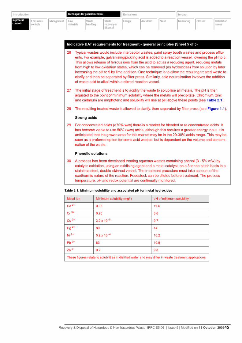
In-process controls
Emissions controls
Management Raw materials
Waste handling
Waste recovery or disposal
Energy Accidents Noise Monitoring Closure Installation issues
Introduction Techniques Emissions Impact
In-process controls
Techniques for pollution control
26 Typical wastes would include interceptor wastes, paint spray booth wastes and process efflu-ents. For example, galvanising/pickling acid is added to a reaction vessel, lowering the pH to 5. This allows release of ferrous ions from the acid to act as a reducing agent, reducing metals from high to low oxidation states, which can be removed (as hydroxides) from solution by later increasing the pH to 9 by lime addition. One technique is to allow the resulting treated waste to clarify and then be separated by filter press. Similarly, acid neutralisation involves the addition of waste acid to alkali within a stirred reaction vessel.
27 The initial stage of treatment is to acidify the waste to solubilise all metals. The pH is then adjusted to the point of minimum solubility where the metals will precipitate. Chromium, zinc and cadmium are amphoteric and solubility will rise at pH above these points (see Table 2.1).
28 The resulting treated waste is allowed to clarify, then separated by filter press (see Figure 1.1).
Strong acids
29 For concentrated acids (>70% w/w) there is a market for blended or re concentrated acids. It has become viable to use 50% (w/w) acids, although this requires a greater energy input. It is anticipated that the growth area for this market may be in the 20-30% acids range. This may be seen as a preferred option for some acid wastes, but is dependent on the volume and contami-nation of the waste.
Phenolic solutions
30 A process has been developed treating aqueous wastes containing phenol (3 - 5% w/w) by catalytic oxidation, using an oxidising agent and a metal catalyst, on a 3 tonne batch basis in a stainless-steel, double-skinned vessel. The treatment procedure must take account of the exothermic nature of the reaction. Feedstock can be diluted before treatment. The process temperature, pH and redox potential are continually monitored.
Table 2.1: Minimum solubility and associated pH for metal hydroxides
Metal Ion Minimum solubility (mg/l) pH of minimum solubility
Cd 2+ 0.05 11.4
Cr 3+ 0.26 8.6
Cu 2+ 3.2 x 10 -5 9.7
Hg 2+ 80 >4
Ni 2+ 5.9 x 10 -4 10.2
Pb 2+ 83 10.9
Zn 2+ 0.2 9.8
These figures relate to solubilities in distilled water and may differ in waste treatment applications.
Indicative BAT requirements for treatment - general principles (Sheet 5 of 5)
Recovery & Disposal of Hazardous & Non-hazardous Waste IPPC S5.06 | Issue 5 | Modified on 13 October, 200345
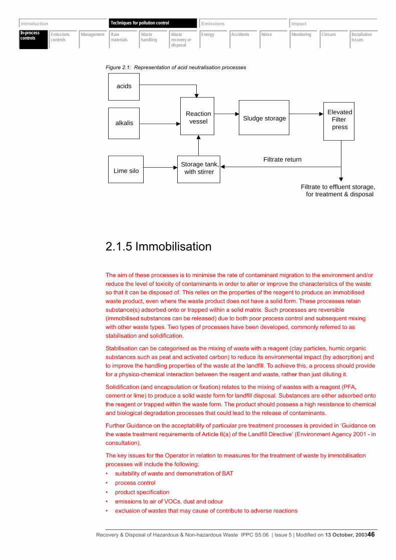
In-process controls
Emissions controls
Management Raw materials
Waste handling
Waste recovery or disposal
Energy Accidents Noise Monitoring Closure Installation issues
Introduction Techniques Emissions Impact
In-process controls
Techniques for pollution control
Figure 2.1: Representation of acid neutralisation processes
2.1.5 Immobilisation
The aim of these processes is to minimise the rate of contaminant migration to the environment and/or reduce the level of toxicity of contaminants in order to alter or improve the characteristics of the waste so that it can be disposed of. This relies on the properties of the reagent to produce an immobilised waste product, even where the waste product does not have a solid form. These processes retain substance(s) adsorbed onto or trapped within a solid matrix. Such processes are reversible (immobilised substances can be released) due to both poor process control and subsequent mixing with other waste types. Two types of processes have been developed, commonly referred to as stabilisation and solidification.
Stabilisation can be categorised as the mixing of waste with a reagent (clay particles, humic organic substances such as peat and activated carbon) to reduce its environmental impact (by adsorption) and to improve the handling properties of the waste at the landfill. To achieve this, a process should provide for a physico-chemical interaction between the reagent and waste, rather than just diluting it.
Solidification (and encapsulation or fixation) relates to the mixing of wastes with a reagent (PFA, cement or lime) to produce a solid waste form for landfill disposal. Substances are either adsorbed onto the reagent or trapped within the waste form. The product should possess a high resistance to chemical and biological degradation processes that could lead to the release of contaminants.
Further Guidance on the acceptability of particular pre treatment processes is provided in ‘Guidance on the waste treatment requirements of Article 6(a) of the Landfill Directive’ (Environment Agency 2001 - in consultation).
The key issues for the Operator in relation to measures for the treatment of waste by immobilisation processes will include the following:• suitability of waste and demonstration of BAT• process control• product specification• emissions to air of VOCs, dust and odour• exclusion of wastes that may cause of contribute to adverse reactions
Reactionvesselalkalis
acids
Storage tank,with stirrerLime silo
Sludge storageElevated
Filterpress
Filtrate to effluent storage,for treatment & disposal
Filtrate return
Recovery & Disposal of Hazardous & Non-hazardous Waste IPPC S5.06 | Issue 5 | Modified on 13 October, 200346
In-process controls
Emissions controls
Management Raw materials
Waste handling
Waste recovery or disposal
Energy Accidents Noise Monitoring Closure Installation issues
Introduction Techniques Emissions Impact
In-process controls
Techniques for pollution control
The Operator must clearly define and describe the process, its objectives and environmental benefits. Such benefits must be justified in terms of the pre treatment requirements and waste acceptance criteria of the Landfill Directive.
Under the Landfill Directive the end-product specification will eventually need to align with the acceptance criteria for the receiving landfill, which has been set by the European Technical Adaptation Committee covering leachability, physical stability and reaction with other wastes. (2003/33/EC: Council Decision of 19 December 2002 establishing criteria and procedures for the acceptance of waste at landfills pursuant to Article 16 of and Annex II to Directive 1999/31/EC Official Journal L 011, 16/01/2003 P. 0027 - 0049)
In the past stabilisation has been used to dispose of aerosols, clinical wastes, explosives, laboratory small’s, shredded drums and containers, this is not acceptable and does not constitute BAT.
Indicative BAT requirements for immobilisation (Sheet 1 of 3)
General principles
31 Simple physical dilution or absorption, without any concurrent physico-chemical change, is not an acceptable treatment process. For example, the absorption of a liquid into sawdust such that it is no longer a liquid waste is not acceptable as a pre treatment for landfill.
32 The acceptable range of characteristics of a waste that can be effectively treated by the process should be defined. This range will be determined by the ability of the process to immo-bilise the chemical/ion in question to ensure that the final product can meet a defined specification. These techniques are most likely to be effective upon the treatment of inorganic wastes where solubility is already quite low.
33 All immobilisation processes should take place within suitably designed reaction vessels with suitable process monitoring within enclosed and abated systems.
Pre acceptance procedures to assess waste
34 Wastes not suitable for immobilisation include:• Flammable and highly flammable wastes1
• Wastes containing volatile substances2
• Oxidising agents• Odorous wastes
35 Quality control (to include leachability tests) should include screening each proposed waste to ensure that any wastes containing process inhibitors are excluded. For each waste stream, laboratory scale testing should be carried out to maximise effectiveness of the mix and quantity of absorbents/binders to be added, identifying an optimum “formula” to be used in full scale treatment should the waste stream in question subsequently be found suitable. Any such testing should take into account effects of different waste streams being treated in the same batch and in addition identify a minimum residence time within the reaction vessel. Records of which waste streams have been pretested should be kept showing whether they have been accepted or rejected as being suitable for treatment by the process.
Acceptance procedures when waste arrives at the installation
36 Quality control (to include leachability tests) should be conducted on every load prior to treat-ment, to confirm the levels of key indicator substances identified at the pre-acceptance stage.
Monitoring of process variables
37 The on-site laboratory forms the essential element in providing assurance that the necessary process input controls are in place and that a consistent end-product is produced.
Recovery & Disposal of Hazardous & Non-hazardous Waste IPPC S5.06 | Issue 5 | Modified on 13 October, 200347
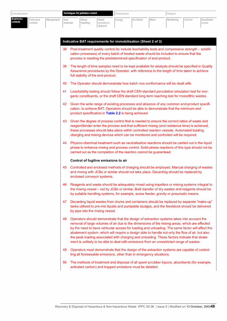
In-process controls
Emissions controls
Management Raw materials
Waste handling
Waste recovery or disposal
Energy Accidents Noise Monitoring Closure Installation issues
Introduction Techniques Emissions Impact
In-process controls
Techniques for pollution control
38 Post-treatment quality control (to include leachability tests and compressive strength – solidifi-cation processes) of every batch of treated waste should be included to ensure that the process is meeting the predetermined specification of end-product.
39 The length of time samples need to be kept available for analysis should be specified in Quality Assurance procedures by the Operator, with reference to the length of time taken to achieve full stability of the end-product.
40 The Operator should demonstrate how batch non-conformance will be dealt with.
41 Leachability testing should follow the draft CEN standard percolation simulation test for inor-ganic constituents, or the draft CEN standard long-term leaching test for monolithic wastes.
42 Given the wide range of existing processes and absence of any common end-product specifi-cation, to achieve BAT, Operators should be able to demonstrate that the minimum end product specification in Table 2.2 is being achieved.
43 Given the degree of process control that is needed to ensure the correct ratios of waste and reagent/binder enter the process and that sufficient mixing (and residence time) is achieved, these processes should take place within controlled reaction vessels. Automated loading, charging and mixing devices which can be monitored and controlled will be required.
44 Physico-chemical treatment such as neutralisation reactions should be carried out in the liquid phase to enhance mixing and process control. Solid-phase reactions of this type should not be carried out as the completion of the reaction cannot be guaranteed.
Control of fugitive emissions to air
45 Controlled and enclosed methods of charging should be employed. Manual charging of wastes and mixing with JCBs or similar should not take place. Decanting should be replaced by enclosed conveyor systems.
46 Reagents and waste should be adequately mixed using impellers or mixing systems integral to the mixing vessel – not by JCBs or similar. Bulk transfer of dry wastes and reagents should be by suitable handling systems, for example, screw feeder, gravity or pneumatic means.
47 Decanting liquid wastes from drums and containers should be replaced by separate “make-up” tanks utilised to pre-mix liquids and pumpable sludges, and the feedstock should be delivered by pipe into the mixing vessel.
48 Operators should demonstrate that the design of extraction systems takes into account the removal of large volumes of air due to the dimensions of the mixing areas, which are effected by the need to have vehicular access for loading and unloading. The same factor will affect the abatement system, which will require a design able to handle not only the flow of air, but also the peak loading associated with charging and unloading. These factors indicate that abate-ment is unlikely to be able to deal with emissions from an unrestricted range of wastes.
49 Operators must demonstrate that the design of the extraction systems are capable of control-ling all foreseeable emissions, other than in emergency situations.
50 The methods of treatment and disposal of all spent scrubber liquors, absorbents (for example, activated carbon) and trapped emissions must be detailed.
Indicative BAT requirements for immobilisation (Sheet 2 of 3)
Recovery & Disposal of Hazardous & Non-hazardous Waste IPPC S5.06 | Issue 5 | Modified on 13 October, 200348
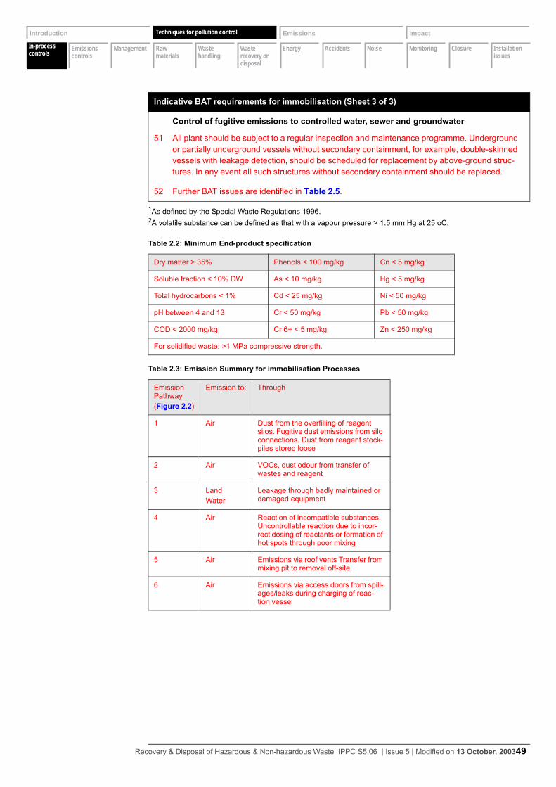
In-process controls
Emissions controls
Management Raw materials
Waste handling
Waste recovery or disposal
Energy Accidents Noise Monitoring Closure Installation issues
Introduction Techniques Emissions Impact
In-process controls
Techniques for pollution control
Control of fugitive emissions to controlled water, sewer and groundwater
51 All plant should be subject to a regular inspection and maintenance programme. Underground or partially underground vessels without secondary containment, for example, double-skinned vessels with leakage detection, should be scheduled for replacement by above-ground struc-tures. In any event all such structures without secondary containment should be replaced.
52 Further BAT issues are identified in Table 2.5.
1As defined by the Special Waste Regulations 1996.2A volatile substance can be defined as that with a vapour pressure > 1.5 mm Hg at 25 oC.
Table 2.2: Minimum End-product specification
Dry matter > 35% Phenols < 100 mg/kg Cn < 5 mg/kg
Soluble fraction < 10% DW As < 10 mg/kg Hg < 5 mg/kg
Total hydrocarbons < 1% Cd < 25 mg/kg Ni < 50 mg/kg
pH between 4 and 13 Cr < 50 mg/kg Pb < 50 mg/kg
COD < 2000 mg/kg Cr 6+ < 5 mg/kg Zn < 250 mg/kg
For solidified waste: >1 MPa compressive strength.
Table 2.3: Emission Summary for immobilisation Processes
Emission Pathway(Figure 2.2)
Emission to: Through
1 Air Dust from the overfilling of reagent silos. Fugitive dust emissions from silo connections. Dust from reagent stock-piles stored loose
2 Air VOCs, dust odour from transfer of wastes and reagent
3 LandWater
Leakage through badly maintained or damaged equipment
4 Air Reaction of incompatible substances. Uncontrollable reaction due to incor-rect dosing of reactants or formation of hot spots through poor mixing
5 Air Emissions via roof vents Transfer from mixing pit to removal off-site
6 Air Emissions via access doors from spill-ages/leaks during charging of reac-tion vessel
Indicative BAT requirements for immobilisation (Sheet 3 of 3)
Recovery & Disposal of Hazardous & Non-hazardous Waste IPPC S5.06 | Issue 5 | Modified on 13 October, 200349
In-process controls
Emissions controls
Management Raw materials
Waste handling
Waste recovery or disposal
Energy Accidents Noise Monitoring Closure Installation issues
Introduction Techniques Emissions Impact
In-process controls
Techniques for pollution control
Figure 2.2: Emission summary for immobilisation processes
2.1.6 Secondary liquid fuel
Blending of solvents for recovery is not a Schedule 1 ‘listed activity’, however it may be undertaken at an installation as a ‘directly associated activity’
The aim of this process is to blend wastes from various sources is used to create a waste fuel in, for example, cement kilns. Wastes utilised include solvents, oil sludges, distillation residues and tank bottom sludges. The quality assurance of these processes is driven by the need to meet the specification set by the receiving facility. The blend in particular is set to meet calorific values and limits on contaminants, for example, chlorine and heavy metals. For further information reference should be made to the Environment Agency’s Substitute Fuels Protocol.
The process includes offloading from drums or bulk tanker via a macerator into primary blending tanks. This is followed by secondary blending, specification checking and storage pending despatch.
Within the UK there are a wide range of waste streams entering into secondary liquid fuel (SLF) production, as control has so far focused on the contractual blend specification agreed between the producer and waste management company. The Regulator will ensure due consideration has been given to whether SLF and recovery within a cement kiln represents BPEO for the waste types identified in the Application.
Prior to receipt at the kiln the waste might have passed through various treatment or blending facilities before final certification of the blend is made. As with other waste streams, a crucial control measure is to ensure adequate transfer of knowledge between holders of the waste. This should ensure that the constituents of all wastes bulked together to form a blend are known and recorded.
1
2
5
4
6
3
ABATEMENT&
MONITORING
ABATEMENT&
MONITORING
REAGENTSILO
PLANTCONTROL
ROOM
TRANSFERTO LANDFILL
AUTOMATEDCHARGINGOF WASTE
REACTIONVESSEL
IMMOBILISATION MIXINGBUILDING
Recovery & Disposal of Hazardous & Non-hazardous Waste IPPC S5.06 | Issue 5 | Modified on 13 October, 200350
In-process controls
Emissions controls
Management Raw materials
Waste handling
Waste recovery or disposal
Energy Accidents Noise Monitoring Closure Installation issues
Introduction Techniques Emissions Impact
In-process controls
Techniques for pollution control
This document addresses the preparation of secondary liquid fuel. Incineration and co-incineration is dealt with under Guidance for the associated sector, for example, incineration or cement and lime.
2.1.7 Oil processing
There are a number of oil treatment activities that fall under this general heading, some examples are;
regeneration of Used Transformer Oil (UTO)
re-refining of used engine oil
production of Recovered Fuel Oil (RFO)
Oil reprocessing to produce RFO is a straightforward process. The processes involved can be described as follows:• storage of feedstock with demulsification, if necessary• heating of the feedstock to drive off the water content• removal of solids
The oil feedstock is characterised by water content and solids content, both of which need to be removed. The activity can be described as a process to remove water and solids from waste oil to produce a secondary fuel oil. Solids are removed by settlement during storage and filtration. Both stages produce a vapour phase that produces VOCs emission to air. The process also produces an aqueous phase contaminated with oil, which requires separation prior to emission to sewer. Solid residues from the storage, process and filtering stages are removed to landfill.
Another option for the re-use of waste oil is to produce base lube oils by re-refining waste oil. This represents a potential higher economic return, but in the medium term it is expected that oil reprocessing will continue to be the primary method of oil recycling. One possible effect of the anticipated expansion of re-refining to produce base lube oils is that this may divert the “cleaner” end of waste oils spectrum into re-refining.
This section deals with the pollution control issues specific to oil reprocessing. These relate to emissions to air, connected to the displacement of VOCs during the reprocessing and associated odour issues. There is also an issue of removing oil from effluent discharged to sewer.
Other issues to do with characterisation of the waste feedstock, prevention of emissions to land and water and prevention of accidents are common to all waste treatment activities under consideration in this document.
Indicative BAT requirements for secondary liquid fuel
1 Pre-acceptance criteria (see Section 2.1.1 on page 22), waste characterisation (see Section 2.1.2 on page 28) and process control (see Section 2.1.4 on page 44).
2 Emissions to air (see Section 2.2.1 on page 64).
3 Emissions to water (see Section 2.2.2 on page 68).
4 Fugitive emissions to air (see Section 2.2.4 on page 76).
5 Accidents (see Section 2.8 on page 97).
Recovery & Disposal of Hazardous & Non-hazardous Waste IPPC S5.06 | Issue 5 | Modified on 13 October, 200351
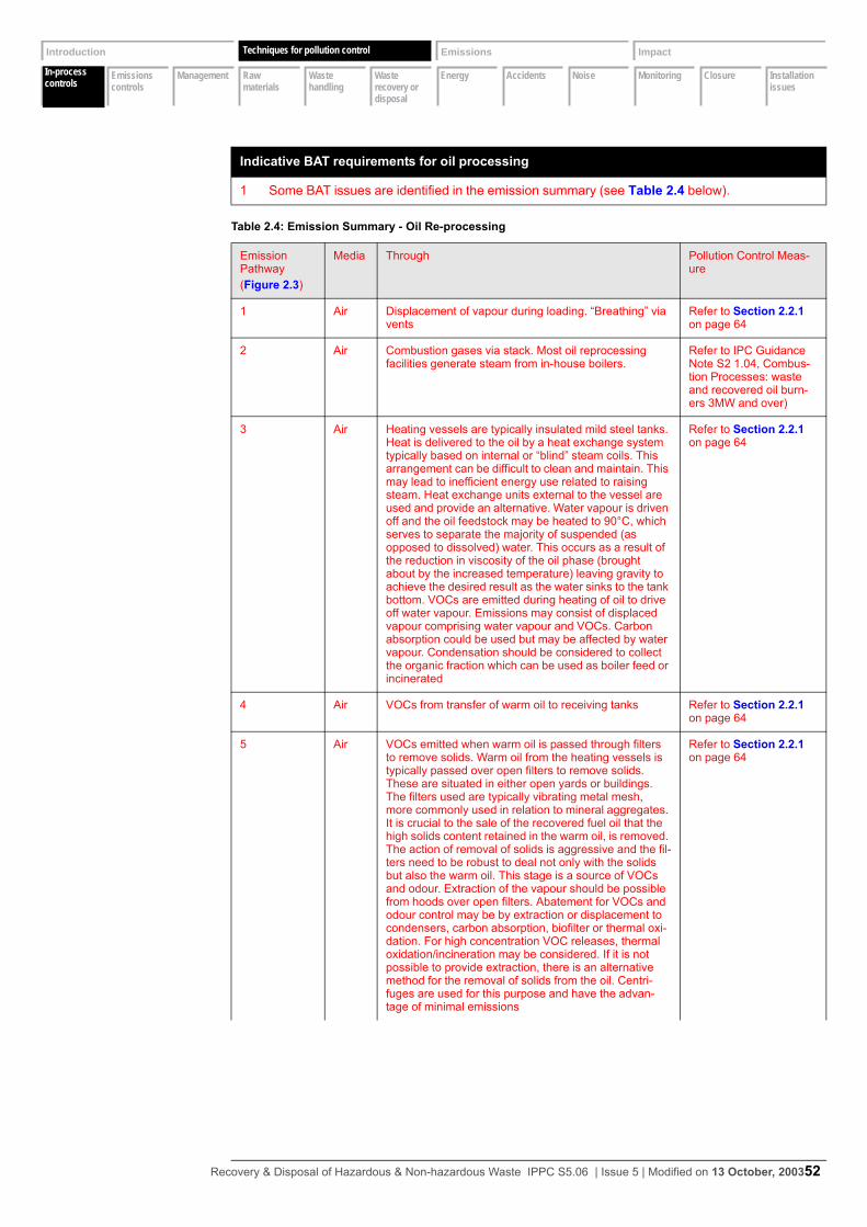
In-process controls
Emissions controls
Management Raw materials
Waste handling
Waste recovery or disposal
Energy Accidents Noise Monitoring Closure Installation issues
Introduction Techniques Emissions Impact
In-process controls
Techniques for pollution control
Indicative BAT requirements for oil processing
1 Some BAT issues are identified in the emission summary (see Table 2.4 below).
Table 2.4: Emission Summary - Oil Re-processing
Emission Pathway(Figure 2.3)
Media Through Pollution Control Meas-ure
1 Air Displacement of vapour during loading. “Breathing” via vents
Refer to Section 2.2.1 on page 64
2 Air Combustion gases via stack. Most oil reprocessing facilities generate steam from in-house boilers.
Refer to IPC Guidance Note S2 1.04, Combus-tion Processes: waste and recovered oil burn-ers 3MW and over)
3 Air Heating vessels are typically insulated mild steel tanks. Heat is delivered to the oil by a heat exchange system typically based on internal or “blind” steam coils. This arrangement can be difficult to clean and maintain. This may lead to inefficient energy use related to raising steam. Heat exchange units external to the vessel are used and provide an alternative. Water vapour is driven off and the oil feedstock may be heated to 90°C, which serves to separate the majority of suspended (as opposed to dissolved) water. This occurs as a result of the reduction in viscosity of the oil phase (brought about by the increased temperature) leaving gravity to achieve the desired result as the water sinks to the tank bottom. VOCs are emitted during heating of oil to drive off water vapour. Emissions may consist of displaced vapour comprising water vapour and VOCs. Carbon absorption could be used but may be affected by water vapour. Condensation should be considered to collect the organic fraction which can be used as boiler feed or incinerated
Refer to Section 2.2.1 on page 64
4 Air VOCs from transfer of warm oil to receiving tanks Refer to Section 2.2.1 on page 64
5 Air VOCs emitted when warm oil is passed through filters to remove solids. Warm oil from the heating vessels is typically passed over open filters to remove solids. These are situated in either open yards or buildings. The filters used are typically vibrating metal mesh, more commonly used in relation to mineral aggregates. It is crucial to the sale of the recovered fuel oil that the high solids content retained in the warm oil, is removed. The action of removal of solids is aggressive and the fil-ters need to be robust to deal not only with the solids but also the warm oil. This stage is a source of VOCs and odour. Extraction of the vapour should be possible from hoods over open filters. Abatement for VOCs and odour control may be by extraction or displacement to condensers, carbon absorption, biofilter or thermal oxi-dation. For high concentration VOC releases, thermal oxidation/incineration may be considered. If it is not possible to provide extraction, there is an alternative method for the removal of solids from the oil. Centri-fuges are used for this purpose and have the advan-tage of minimal emissions
Refer to Section 2.2.1 on page 64
Recovery & Disposal of Hazardous & Non-hazardous Waste IPPC S5.06 | Issue 5 | Modified on 13 October, 200352
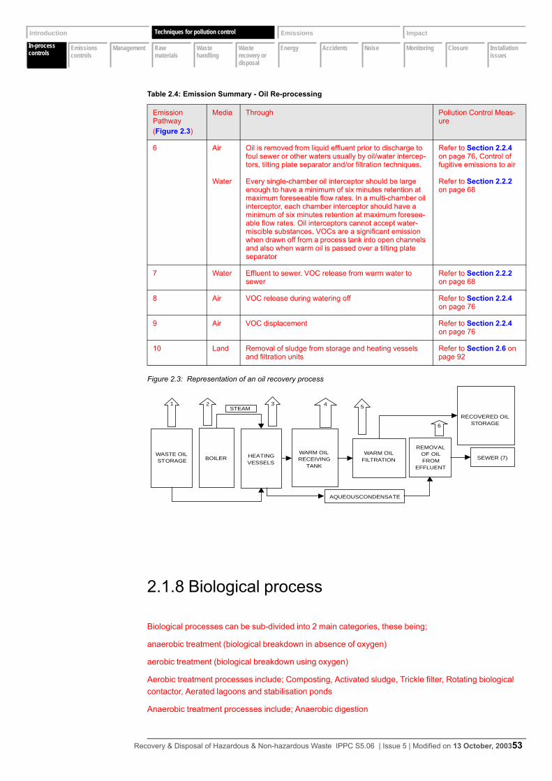
In-process controls
Emissions controls
Management Raw materials
Waste handling
Waste recovery or disposal
Energy Accidents Noise Monitoring Closure Installation issues
Introduction Techniques Emissions Impact
In-process controls
Techniques for pollution control
Figure 2.3: Representation of an oil recovery process
2.1.8 Biological process
Biological processes can be sub-divided into 2 main categories, these being;
anaerobic treatment (biological breakdown in absence of oxygen)
aerobic treatment (biological breakdown using oxygen)
Aerobic treatment processes include; Composting, Activated sludge, Trickle filter, Rotating biological contactor, Aerated lagoons and stabilisation ponds
Anaerobic treatment processes include; Anaerobic digestion
6 Air
Water
Oil is removed from liquid effluent prior to discharge to foul sewer or other waters usually by oil/water intercep-tors, tilting plate separator and/or filtration techniques.
Every single-chamber oil interceptor should be large enough to have a minimum of six minutes retention at maximum foreseeable flow rates. In a multi-chamber oil interceptor, each chamber interceptor should have a minimum of six minutes retention at maximum foresee-able flow rates. Oil interceptors cannot accept water-miscible substances. VOCs are a significant emission when drawn off from a process tank into open channels and also when warm oil is passed over a tilting plate separator
Refer to Section 2.2.4 on page 76, Control of fugitive emissions to air
Refer to Section 2.2.2 on page 68
7 Water Effluent to sewer. VOC release from warm water to sewer
Refer to Section 2.2.2 on page 68
8 Air VOC release during watering off Refer to Section 2.2.4 on page 76
9 Air VOC displacement Refer to Section 2.2.4 on page 76
10 Land Removal of sludge from storage and heating vessels and filtration units
Refer to Section 2.6 on page 92
Table 2.4: Emission Summary - Oil Re-processing
Emission Pathway(Figure 2.3)
Media Through Pollution Control Meas-ure
WARM OILFILTRATION
HEATINGVESSELS
1
REMOVALOF OILFROM
EFFLUENT
2 43
SEWER (7)WASTE OILSTORAGE
RECOVERED OILSTORAGE
BOILER
STEAM
AQUEOUSCONDENSATE
5
WARM OILRECEIVING
TANK
6
Recovery & Disposal of Hazardous & Non-hazardous Waste IPPC S5.06 | Issue 5 | Modified on 13 October, 200353
In-process controls
Emissions controls
Management Raw materials
Waste handling
Waste recovery or disposal
Energy Accidents Noise Monitoring Closure Installation issues
Introduction Techniques Emissions Impact
In-process controls
Techniques for pollution control
The basic principle, common to all, is that natural, micro-organism based activity breaks down certain compounds either through metabolism to provide nutrient energy or through co-metabolism. Effective processing depends on selecting a micro-organism suitable for the species requiring treatment, and on carrying out the treatment under conditions which are suitable, including careful control of the nature and composition of the waste. It is perceived that Biological processes have little effect on inorganic wastes including metals, although some absorption into a sludge phase may occur with some processes
The Landfill (England and Wales) Regulations currently prohibits the disposal of liquid hazardous waste in landfill and will exclude the disposal of non-hazardous liquid wastes from landfill within the next few years. This may create an opportunity for existing treatment methods and the development will focus on methods to treat COD. Specific attention will be given to “hard” COD that is not readily susceptible to biodegradation. This could involve the use of dedicated biological techniques, aerobic and/or anaerobic digestion in tandem with chemical oxidation.
Aerobic biological systems are generally more robust than anaerobic systems, which are sensitive to chlorinated and sulphur compounds, pH and temperature fluctuations and may require a pre-acidification stage. Anaerobic systems are more effective at breaking down ring compounds (for example, phenols) and generate methane that can be utilised as a fuel. Aerobic systems may be unsuitable for treating VOC-containing wastes, which may be emitted to air.
Biological plants should be designed to give sufficient residence time to achieve adequate breakdown of the more complex compounds present in the wastewater. Modern aerobic plants have retention times in the order of 23 hours, although a universal figure cannot be given. Sludge age is also important and optimum operating temperatures will also aid degradation. Some aerobic plants are currently
planned to operate at around 30oC.
Other techniques such as fixed film reactors appear to offer certain advantages over activated sludge and trickling filter systems. These include higher hydraulic loading rates (due to higher mineralisation rates), increased biomass stability and resistance to shock loadings and temperature fluctuations.
The presence of substances that are not subject to beneficial treatment, such as toxic metals, must be considered and limits proposed. Dilution or buffering through the works flow is not treatment.
2.1.9 Carbon absorption
This technique has been previously mentioned in connection with VOC abatement, but can also be used as a treatment method, for example, in dealing with aqueous wastes contaminated with pesticides. The spent absorbent is destroyed by incineration.
Indicative BAT requirements for biological processing
1 Refer to Section 2.1.1 on page 22 and Section 2.1.2 on page 28.
Indicative BAT requirements for carbon absorption
1 There are no specific BAT issues for this section.
Recovery & Disposal of Hazardous & Non-hazardous Waste IPPC S5.06 | Issue 5 | Modified on 13 October, 200354
In-process controls
Emissions controls
Management Raw materials
Waste handling
Waste recovery or disposal
Energy Accidents Noise Monitoring Closure Installation issues
Introduction Techniques Emissions Impact
In-process controls
Techniques for pollution control
2.1.10 Wet air oxidation
Attention has been given to the development of destructive physico-chemical treatment methods for aqueous effluents with high COD, which would not be suitable for direct discharge to a WwTW, but would be too expensive to incinerate.
Attempts at using wet air oxidation for merchant waste treatment has suffered from problems connected with heterogeneous and variable waste feedstock. There are no current applications in merchant waste treatment.
A pharmaceutical manufacturer near Newcastle operates a Zimpro Wet Air Oxidation system, and a chemical manufacturer in West Yorkshire has recently installed a BOC Gases Loprox and Vitox oxidation plant. This indicates the suitability for using dedicated processes for specific waste streams on waste producer premises.
2.1.11 Air stripping
Ammonia solutions up to 20% w/w can be treated by a dual-column air stripping system with acidic scrubber. A dual-column process has been developed, in which the initial column raises the temperature of the feedstock and maintains the pH between 10 and 11. The feedstock is transferred to the second column, where it is run counter-current across a packed column against air. The ammonia removed in the gas phase is scrubbed with sulphuric acid to produce ammonium sulphate.
2.1.12 Settlement
Settlement involves settling by gravity, and is used in waste treatment for the removal of particulate and colloidal solids, and flocculent suspensions arising from acid-alkali reactions to precipitate metals out of solution. The efficiency of the sedimentation process is affected by the wastewater and suspended solids characteristics, variation in flow and general operation. The solids may be discrete suspended particles that are self-settling, or they may be of a range of sizes and surface characteristics, which require the formation of flocculating suspensions to coagulate and settle the mass, through chemical
Indicative BAT requirements for wet air oxidation
1 Refer to Section 2.1.1 on page 22 and Section 2.1.2 on page 28.
2 See Section 2.10 on page 105 and Table 2.17.
Indicative BAT requirements for air stripping
1 There are no specific BAT issues for this section.
Recovery & Disposal of Hazardous & Non-hazardous Waste IPPC S5.06 | Issue 5 | Modified on 13 October, 200355
In-process controls
Emissions controls
Management Raw materials
Waste handling
Waste recovery or disposal
Energy Accidents Noise Monitoring Closure Installation issues
Introduction Techniques Emissions Impact
In-process controls
Techniques for pollution control
conditioning. Settlement is carried out in clarifiers that should be specifically designed with an inlet, outlet, settling zone and sludge blanket (or sludge zone). Sludges liberated from a settlement stage are typically around 1% dry solids content.
Air flotation is a physical solids separation process relying upon the chemical conditioning of the suspended solids to form a flocculated structure that can be floated to the surface of a reactor by introducing fine bubbles of air. The basic mechanism of air flotation is to introduce small air bubbles into the wastewater containing the suspended solids to be floated. The fine air bubbles attach themselves to the chemically conditioned particles and hence the solids float to the surface, where they are accumulated, thickened and removed by mechanical skimming or suction withdrawal. Usually chemicals such as polymers, aluminium sulphate or ferric chloride are used to enhance the adhesion of bubbles. The method of air supply is used to define the process.
Flotation is used when gravity settlement is not appropriate, for example, when:• the particulates have poor gravity settling characteristics• the density difference between the suspended particles and water is too low• there is a space constraint at the site• oil and grease are to be removed• recovery of material is required
Dissolved air flotation (DAF) is most widely used because of its effectiveness in removing a range of solids. The DAF system generates a supersaturated solution of wastewater and compressed air by raising the pressure of the wastewater stream to that of the compressed air, then mixing the two in a retention tank. This supersaturated mixture of air and wastewater flows to a large flotation tank where the pressure is released, thereby generating numerous small air bubbles. Through a combination of adsorption and entrapment, the flocculated particles rise to the surface of the reactor. The suspended solids float to the top of the liquid and form a foam that is then skimmed off. Some soluble colloidal substances are removed from the wastewater by adding coagulation and flocculation chemicals (e.g. iron salts, aluminium salts and polyelectrolytes) to form precipitates with the solutes.
2.1.13 Drum washing, crushing, shredding and cutting
Drum washing and cutting operations must take account of the former contents and any residues that may be present. Containers used to store cut drums/IBCs should be covered.
Drum crushers/shredders are typically used for two purposes:• extracting wastes that are difficult to pump or decant• as a means of reducing the volume of a drum containing a residue that is difficult to pump or decant
Most plant comprises a proprietary compaction unit. There are examples of modified processes, which may be as simple as a metal spike onto which drums are dropped. Regardless of the technique employed, there is usually no provision for environmental control and the emissions are dependent on the composition of the waste held within the drum.
Indicative BAT requirements for settlement
1 Refer to Section 2.10 on page 105 and Table 2.17.
Recovery & Disposal of Hazardous & Non-hazardous Waste IPPC S5.06 | Issue 5 | Modified on 13 October, 200356
In-process controls
Emissions controls
Management Raw materials
Waste handling
Waste recovery or disposal
Energy Accidents Noise Monitoring Closure Installation issues
Introduction Techniques Emissions Impact
In-process controls
Techniques for pollution control
An example of suitable plant consists of a fume-extracted enclosure mounted on a raised platform and containing a hydraulically operated remotely controlled crushing head. Waste residues expelled from the drums during crushing are passed via an enclosed chute into a drum placed underneath the elevated platform. Vapours are extracted through an oil scrubber and two activated carbon filters in series, before discharge to atmosphere. Interlocks prevent operation of the crusher when either the crusher door is open or the abatement system is not operating.
Drum crushing/shredding units should not vent direct to atmosphere unless washed and fully purged of their former contents. Where nominally empty drums or drums containing wastes are crushed or shredded, units should not vent direct to atmosphere. The mixing of some wastes may create flammable atmospheres and there is also the possibility of static discharges with some types and mixes of wastes and reagents.
Indicative BAT requirements for drum washing, crushing, shredding and cutting
1 BAT for pre-acceptance criteria (see Section 2.1.1 on page 22), waste characterisation (see Section 2.1.2 on page 28) and process control (see Section 2.1.4 on page 44) are outlined in earlier sections.
2 Drums containing (or which have contained):• flammable and highly flammable wastes1
• volatile substances2
3 should not be subject to crushing, unless the residues have been removed and the drum cleaned.
4 Empty containers that are in sound condition and are free from or contain insignificant quanti-ties of residual waste should be sent for reconditioning and re-use or recycling.
5 Processing containers should only be undertaken following written instruction. These instruc-tions should include which batch is to be processed and the type of container to hold residues.
6 Emissions to air (see Section 2.2.1 on page 64) should be reduced by ensuring:• drum crushing and shredding plant is fitted with an extractive vent system linked to abate-
ment, for example, an oil scrubber and activated carbon filter• the abatement system should be interlocked such that the plant cannot operate unless the
abatement system is working• all cutting operations should be subject to LEV
7 BAT techniques for emissions to water are outlined in Section 2.2.2 on page 68, and include the need to:• keep skips for the storage of crushed/cut drums covered• sealed system, e.g. chute, for containment of residues• sealed drainage (see Section 2.8 on page 97)
8 BAT for fugitive emissions to air are outlined in Section 2.2.4 on page 76.
9 BAT for accident reduction are outlined in see Section 2.8 on page 97.
1As defined by the Special Waste Regulations 1996.2A volatile substance can be defined as that with a vapour pressure > 1.5 mm Hg at 25 oC.
Recovery & Disposal of Hazardous & Non-hazardous Waste IPPC S5.06 | Issue 5 | Modified on 13 October, 200357
In-process controls
Emissions controls
Management Raw materials
Waste handling
Waste recovery or disposal
Energy Accidents Noise Monitoring Closure Installation issues
Introduction Techniques Emissions Impact
In-process controls
Techniques for pollution control
2.1.14 Road tanker washing
Most treatment plants incorporate a washing-out facility to enable the removal of residues from vehicle tanker barrels. In some cases, vapours may become trapped within the sludges. BAT for road vehicle washing includes appropriate actions to avoid any uncontrolled releases, and the identification of intrinsic hazard or potential pollution problem at the waste characterisation stages for residues of wastes that have been delivered to the installation. In this case the washings can be transferred to appropriate storage and treated in the same way as the waste from which it was derived.
Washings from vehicle wash-out should be transferred to appropriate storage and dealt with in the same way as the parent waste.
2.1.15 Sludge treatment and disposal
In terms of capital expenditure and operating costs, sludge treatment is a significant component, and the management and disposal of solid waste will remain as one of the most fundamental issues facing the Operator.
Sludges that are taken from the bottom of settlement tanks will generally be around 0.5 -1.0% dry solids content, with slightly higher values (up to 4% dry solids) for dissolved air flotation.
Sludge dewatering increases the dry solids content of a sludge, producing a “solid” waste. It is a grey area as to where a liquid sludge becomes a solid waste; however, any sludge over 10% dry solids becomes difficult and expensive to pump. Dewatering produces a sludge “cake”, which may be between 20 and 50% dry solids, which will in turn significantly reduce disposal costs.
In most cases, further dewatering will first require some form of chemical conditioning to assist in the separation of the bound and entrained water from within the sludge. There is a wide range of high molecular weight polymeric flocculents that are particularly effective, and the high price of such chemicals should be more than offset by the improvement in performance of the dewatering process. A number of sludge dewatering processes exist, and selection will depend upon the nature and frequency of solids produced, and the sludge cake required. Examples include:• Filter (or plate) presses which are batch processes, and can be manually intensive. The “plates” are
covered with a suitable filter cloth (dependent upon the application) and the sludge is fed into the plate cavity. The sludge is dewatered under pressure with the filtrate passing through the filter cloth. Once the pressure is released and the plates separated, the cake is either manually scraped off or vibration mechanisms employed to automate the process. A filter press can produce up to 40% dry solids cake.
• The belt press continuous process with a filter cloth continually running through rollers that force-fully dewater the sludge. Performance optimisation requires regular and specialised maintenance. A belt press can produce up to 35% dry solids cake. Chemical costs are generally quite high.
• Centrifuges which are also continuous processes that should produce a cake of up to 40% dry sol-ids for certain sludges. Because of the “closed” nature of the centrifuge, associated odour problems are minimal.
Indicative BAT requirements for road tanker washing
1 There are no specific BAT issues for this section.
Recovery & Disposal of Hazardous & Non-hazardous Waste IPPC S5.06 | Issue 5 | Modified on 13 October, 200358

In-process controls
Emissions controls
Management Raw materials
Waste handling
Waste recovery or disposal
Energy Accidents Noise Monitoring Closure Installation issues
Introduction Techniques Emissions Impact
In-process controls
Techniques for pollution control
Indicative BAT requirements for sludge treatment
1 Storage of filter cake and filter press should be under cover, subject to LEV and with drainage to storage and treatment.
2 Provision should be made to prevent filter cake being carried out of the storage area on vehicle wheels and dust generation from the storage and loading areas.
3 Analysis of the sludge/filter cake should be undertaken to ensure that the treatment process objectives are being met and the process is working effectively.
Recovery & Disposal of Hazardous & Non-hazardous Waste IPPC S5.06 | Issue 5 | Modified on 13 October, 200359

In-process controls
Emissions controls
Management Raw materials
Waste handling
Waste recovery or disposal
Energy Accidents Noise Monitoring Closure Installation issues
Introduction Techniques Emissions Impact
Emissions control
Techniques for pollution control
2.2 Emissions control
2.2.1 Point source emissions to air
The nature and source of the emissions expected from each activity is given in previous sections and the inventory of emissions should be confirmed in detail in the Application.
Point source emissions relate to those emissions that result from the collection of gas from a vessel or area and are passed either via abatement or direct to a stack or vent.
Table 2.5: Point Source Emissions to Air
Activity Emission point Abatement options for specified pollutants
PHYSICAl-CHEMI-CAL TREATMENT
VOCs Odour Particu-late
NH3, H2S, Amines
Acid gases
Acid-Alkali neutralisa-tion
Reactor vessel Ab, Ad, To
Ab, Ad, To
Ab Ab
STABILISATION Mixing vessel Ab, Ad, To
Ab, Ad, To
Ff, Cy
OIL REPROCESSING Heating vessels Co, To Co, To, Bo
Warm oilreceiving tanks
Co, To Co, To, Bo
Filtration systems
Co, To Co, To, Bo
BULKING UP AND TRANSFER OF WASTE
Ad Ad
SECONDARY LIQUID FUEL BLENDING
Ad, Ab, To
Ad, Ab
DRUM CRUSHING AND SHREDDING
Ad, Ab Ad, Ab
See Table 2.6 on page 65 for air abatement options key.
Recovery & Disposal of Hazardous & Non-hazardous Waste IPPC S5.06 | Issue 5 | Modified on 13 October, 200360
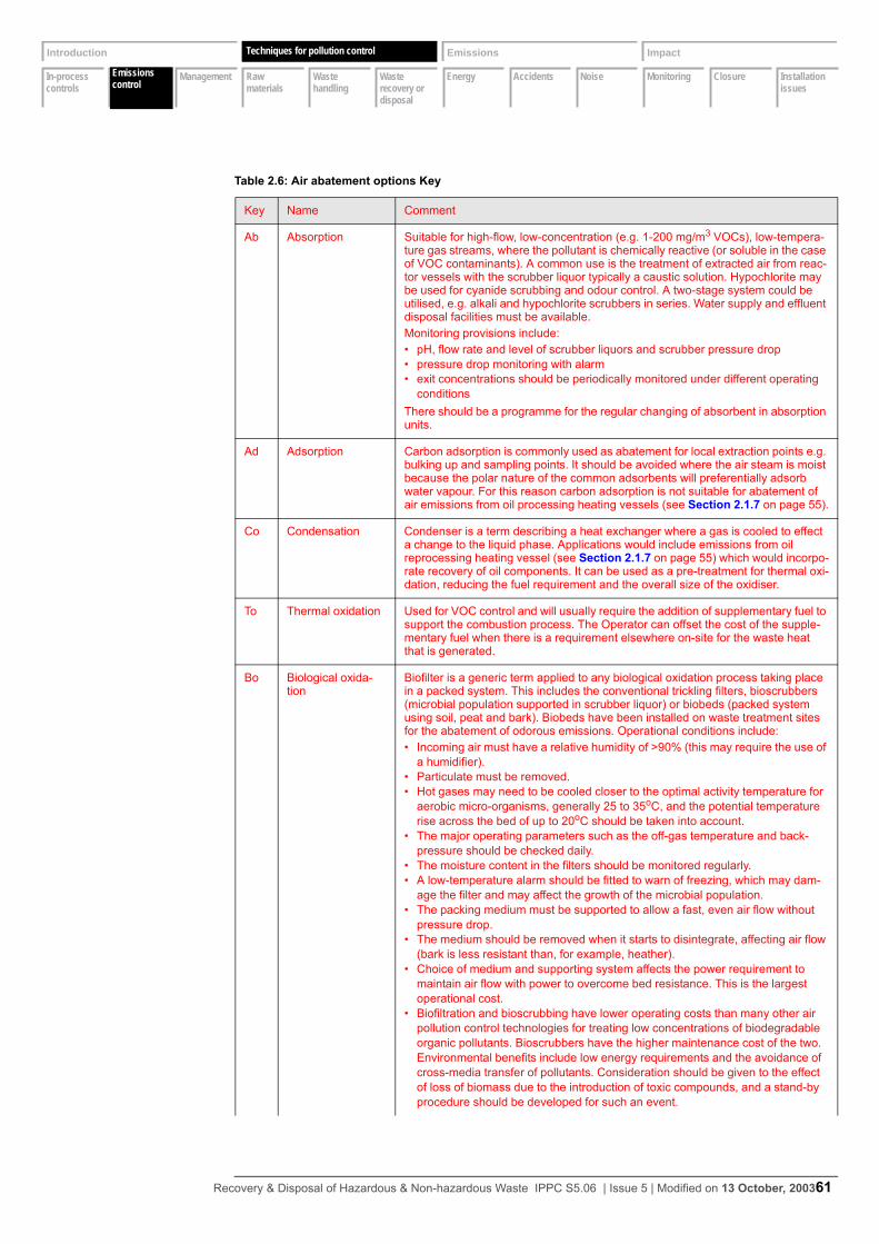
In-process controls
Emissions controls
Management Raw materials
Waste handling
Waste recovery or disposal
Energy Accidents Noise Monitoring Closure Installation issues
Introduction Techniques Emissions Impact
Emissions control
Techniques for pollution control
Table 2.6: Air abatement options Key
Key Name Comment
Ab Absorption Suitable for high-flow, low-concentration (e.g. 1-200 mg/m3 VOCs), low-tempera-ture gas streams, where the pollutant is chemically reactive (or soluble in the case of VOC contaminants). A common use is the treatment of extracted air from reac-tor vessels with the scrubber liquor typically a caustic solution. Hypochlorite may be used for cyanide scrubbing and odour control. A two-stage system could be utilised, e.g. alkali and hypochlorite scrubbers in series. Water supply and effluent disposal facilities must be available.Monitoring provisions include:• pH, flow rate and level of scrubber liquors and scrubber pressure drop• pressure drop monitoring with alarm• exit concentrations should be periodically monitored under different operating
conditionsThere should be a programme for the regular changing of absorbent in absorption units.
Ad Adsorption Carbon adsorption is commonly used as abatement for local extraction points e.g. bulking up and sampling points. It should be avoided where the air steam is moist because the polar nature of the common adsorbents will preferentially adsorb water vapour. For this reason carbon adsorption is not suitable for abatement of air emissions from oil processing heating vessels (see Section 2.1.7 on page 55).
Co Condensation Condenser is a term describing a heat exchanger where a gas is cooled to effect a change to the liquid phase. Applications would include emissions from oil reprocessing heating vessel (see Section 2.1.7 on page 55) which would incorpo-rate recovery of oil components. It can be used as a pre-treatment for thermal oxi-dation, reducing the fuel requirement and the overall size of the oxidiser.
To Thermal oxidation Used for VOC control and will usually require the addition of supplementary fuel to support the combustion process. The Operator can offset the cost of the supple-mentary fuel when there is a requirement elsewhere on-site for the waste heat that is generated.
Bo Biological oxida-tion
Biofilter is a generic term applied to any biological oxidation process taking place in a packed system. This includes the conventional trickling filters, bioscrubbers (microbial population supported in scrubber liquor) or biobeds (packed system using soil, peat and bark). Biobeds have been installed on waste treatment sites for the abatement of odorous emissions. Operational conditions include:• Incoming air must have a relative humidity of >90% (this may require the use of
a humidifier).• Particulate must be removed.• Hot gases may need to be cooled closer to the optimal activity temperature for
aerobic micro-organisms, generally 25 to 35oC, and the potential temperature rise across the bed of up to 20oC should be taken into account.
• The major operating parameters such as the off-gas temperature and back-pressure should be checked daily.
• The moisture content in the filters should be monitored regularly.• A low-temperature alarm should be fitted to warn of freezing, which may dam-
age the filter and may affect the growth of the microbial population.• The packing medium must be supported to allow a fast, even air flow without
pressure drop.• The medium should be removed when it starts to disintegrate, affecting air flow
(bark is less resistant than, for example, heather).• Choice of medium and supporting system affects the power requirement to
maintain air flow with power to overcome bed resistance. This is the largest operational cost.
• Biofiltration and bioscrubbing have lower operating costs than many other air pollution control technologies for treating low concentrations of biodegradable organic pollutants. Bioscrubbers have the higher maintenance cost of the two. Environmental benefits include low energy requirements and the avoidance of cross-media transfer of pollutants. Consideration should be given to the effect of loss of biomass due to the introduction of toxic compounds, and a stand-by procedure should be developed for such an event.
Recovery & Disposal of Hazardous & Non-hazardous Waste IPPC S5.06 | Issue 5 | Modified on 13 October, 200361
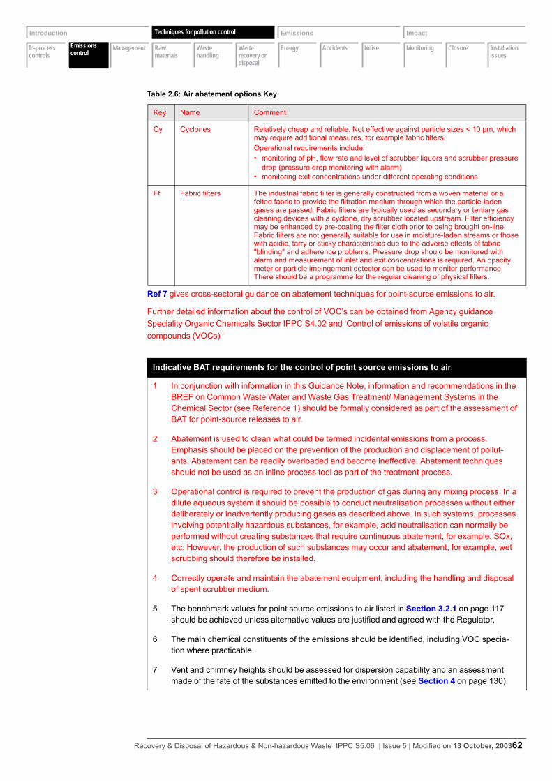
In-process controls
Emissions controls
Management Raw materials
Waste handling
Waste recovery or disposal
Energy Accidents Noise Monitoring Closure Installation issues
Introduction Techniques Emissions Impact
Emissions control
Techniques for pollution control
Ref 7 gives cross-sectoral guidance on abatement techniques for point-source emissions to air.
Further detailed information about the control of VOC’s can be obtained from Agency guidance Speciality Organic Chemicals Sector IPPC S4.02 and ‘Control of emissions of volatile organic compounds (VOCs) ‘
Cy Cyclones Relatively cheap and reliable. Not effective against particle sizes < 10 µm, which may require additional measures, for example fabric filters.Operational requirements include:• monitoring of pH, flow rate and level of scrubber liquors and scrubber pressure
drop (pressure drop monitoring with alarm)• monitoring exit concentrations under different operating conditions
Ff Fabric filters The industrial fabric filter is generally constructed from a woven material or a felted fabric to provide the filtration medium through which the particle-laden gases are passed. Fabric filters are typically used as secondary or tertiary gas cleaning devices with a cyclone, dry scrubber located upstream. Filter efficiency may be enhanced by pre-coating the filter cloth prior to being brought on-line. Fabric filters are not generally suitable for use in moisture-laden streams or those with acidic, tarry or sticky characteristics due to the adverse effects of fabric "blinding" and adherence problems. Pressure drop should be monitored with alarm and measurement of inlet and exit concentrations is required. An opacity meter or particle impingement detector can be used to monitor performance. There should be a programme for the regular cleaning of physical filters.
Indicative BAT requirements for the control of point source emissions to air
1 In conjunction with information in this Guidance Note, information and recommendations in the BREF on Common Waste Water and Waste Gas Treatment/ Management Systems in the Chemical Sector (see Reference 1) should be formally considered as part of the assessment of BAT for point-source releases to air.
2 Abatement is used to clean what could be termed incidental emissions from a process. Emphasis should be placed on the prevention of the production and displacement of pollut-ants. Abatement can be readily overloaded and become ineffective. Abatement techniques should not be used as an inline process tool as part of the treatment process.
3 Operational control is required to prevent the production of gas during any mixing process. In a dilute aqueous system it should be possible to conduct neutralisation processes without either deliberately or inadvertently producing gases as described above. In such systems, processes involving potentially hazardous substances, for example, acid neutralisation can normally be performed without creating substances that require continuous abatement, for example, SOx, etc. However, the production of such substances may occur and abatement, for example, wet scrubbing should therefore be installed.
4 Correctly operate and maintain the abatement equipment, including the handling and disposal of spent scrubber medium.
5 The benchmark values for point source emissions to air listed in Section 3.2.1 on page 117 should be achieved unless alternative values are justified and agreed with the Regulator.
6 The main chemical constituents of the emissions should be identified, including VOC specia-tion where practicable.
7 Vent and chimney heights should be assessed for dispersion capability and an assessment made of the fate of the substances emitted to the environment (see Section 4 on page 130).
Table 2.6: Air abatement options Key
Key Name Comment
Recovery & Disposal of Hazardous & Non-hazardous Waste IPPC S5.06 | Issue 5 | Modified on 13 October, 200362
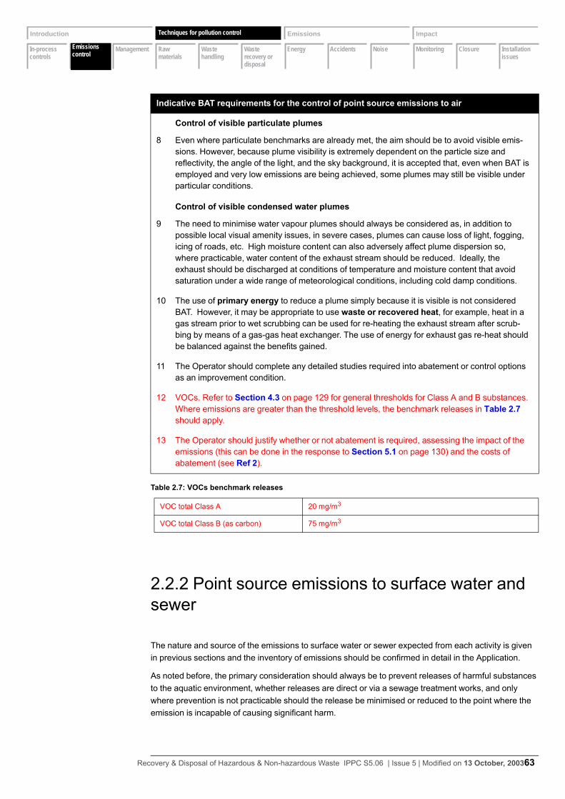
In-process controls
Emissions controls
Management Raw materials
Waste handling
Waste recovery or disposal
Energy Accidents Noise Monitoring Closure Installation issues
Introduction Techniques Emissions Impact
Emissions control
Techniques for pollution control
2.2.2 Point source emissions to surface water and sewer
The nature and source of the emissions to surface water or sewer expected from each activity is given in previous sections and the inventory of emissions should be confirmed in detail in the Application.
As noted before, the primary consideration should always be to prevent releases of harmful substances to the aquatic environment, whether releases are direct or via a sewage treatment works, and only where prevention is not practicable should the release be minimised or reduced to the point where the emission is incapable of causing significant harm.
Control of visible particulate plumes
8 Even where particulate benchmarks are already met, the aim should be to avoid visible emis-sions. However, because plume visibility is extremely dependent on the particle size and reflectivity, the angle of the light, and the sky background, it is accepted that, even when BAT is employed and very low emissions are being achieved, some plumes may still be visible under particular conditions.
Control of visible condensed water plumes
9 The need to minimise water vapour plumes should always be considered as, in addition to possible local visual amenity issues, in severe cases, plumes can cause loss of light, fogging, icing of roads, etc. High moisture content can also adversely affect plume dispersion so, where practicable, water content of the exhaust stream should be reduced. Ideally, the exhaust should be discharged at conditions of temperature and moisture content that avoid saturation under a wide range of meteorological conditions, including cold damp conditions.
10 The use of primary energy to reduce a plume simply because it is visible is not considered BAT. However, it may be appropriate to use waste or recovered heat, for example, heat in a gas stream prior to wet scrubbing can be used for re-heating the exhaust stream after scrub-bing by means of a gas-gas heat exchanger. The use of energy for exhaust gas re-heat should be balanced against the benefits gained.
11 The Operator should complete any detailed studies required into abatement or control options as an improvement condition.
12 VOCs. Refer to Section 4.3 on page 129 for general thresholds for Class A and B substances. Where emissions are greater than the threshold levels, the benchmark releases in Table 2.7 should apply.
13 The Operator should justify whether or not abatement is required, assessing the impact of the emissions (this can be done in the response to Section 5.1 on page 130) and the costs of abatement (see Ref 2).
Table 2.7: VOCs benchmark releases
VOC total Class A 20 mg/m3
VOC total Class B (as carbon) 75 mg/m3
Indicative BAT requirements for the control of point source emissions to air
Recovery & Disposal of Hazardous & Non-hazardous Waste IPPC S5.06 | Issue 5 | Modified on 13 October, 200363

In-process controls
Emissions controls
Management Raw materials
Waste handling
Waste recovery or disposal
Energy Accidents Noise Monitoring Closure Installation issues
Introduction Techniques Emissions Impact
Emissions control
Techniques for pollution control
A wide variety of techniques is available for the control of releases to water or sewer, and the BREF on Common Waste Water and Waste Gas Treatment/ Management Systems in the Chemical Sector (see Ref 1) should be consulted. Section 3.3 of the BREF has details of available water treatment techniques and Section 4.3.1 contains recommendations on what might constitute BAT for a variety of treatment techniques for releases to water.
In addition to the BREF and the techniques noted below, guidance on cost-effective effluent treatment techniques can be found in Releases to water references. This includes IPC Technical Guidance Note A4 which summarises techniques of particular relevance to the batch organic chemicals sector.
Waste water can arise from the process, from storm water, from cooling water, from accidental releases of raw materials, products or waste materials, and from fire-fighting. These should all be taken into account when determining the Application.
In addition to the substances that give rise to the COD of the effluent, the raw materials contain persistent organic pollutants, some of which are poorly biodegradable, and which can be particularly toxic.
The effluent will be a complex mixture of substances. For emissions to controlled waters, the use of whole effluent bioassays for the assessment of the complex effluent or the control of process inputs should be considered in conjunction with the Regulator.
The use of direct toxicity assessment (DTA) for environmental assessment is included in the document IPPC Environmental Assessments for BAT and can be used to:• supplement chemical-specific assessments accounting for the effects of substances that might oth-
erwise go undetected• provide an alternative to chemical-specific assessment when there are insufficient ecotoxicological
data on the chemicals of concern
A tiered approach is advocated which might involve not using DTA or using cost-effective high-throughput methods.
A DTA approach should be used as a “trigger” for action by industry to investigate and reduce known ecotoxicity problems rather than applied as a pass/fail licence condition, although there may be occasions where this is needed to deliver environmental improvements or gain and maintain public confidence.
Nature of effluentThe majority of point sources from treatment plants are to foul sewer. Emissions to watercourses and groundwater (under consent) are rare, as they would not meet the relevant EQS. Some installations have no connection to foul sewer and consequently rely on tankering away effluent to another disposal point. The emissions can be summarised as in Table 2.8.
Table 2.8: Point source emissions to water
Emission to Unit Process or Activity
Sewer Physico-chemical treatment
Final effluent from acid-alkali neutralisation and precipitation of metals
Oil reprocessing
Effluent treatment to removal oil from condensate and yard drainage
Cleaning
Recovery & Disposal of Hazardous & Non-hazardous Waste IPPC S5.06 | Issue 5 | Modified on 13 October, 200364
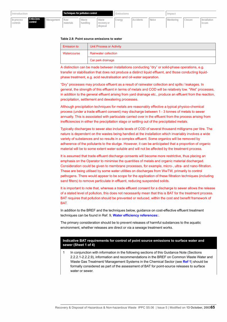
In-process controls
Emissions controls
Management Raw materials
Waste handling
Waste recovery or disposal
Energy Accidents Noise Monitoring Closure Installation issues
Introduction Techniques Emissions Impact
Emissions control
Techniques for pollution control
A distinction can be made between installations conducting “dry” or solid-phase operations, e.g. transfer or stabilisation that does not produce a distinct liquid effluent, and those conducting liquid-phase treatment, e.g. acid neutralisation and oil-water separation.
“Dry” processes may produce effluent as a result of rainwater collection and spills / leakages. In general, the strength of this effluent in terms of metals and COD will be relatively low. “Wet” processes, in addition to the general effluent arising from yard drainage etc., produce an effluent from the reaction, precipitation, settlement and dewatering processes.
Although precipitation techniques for metals are reasonably effective a typical physico-chemical process (under a trade effluent consent) may discharge between 1 - 3 tonnes of metals to sewer annually. This is associated with particulate carried over in the effluent from the process arising from inefficiencies in either the precipitation stage or settling out of the precipitated metals.
Typically discharges to sewer also include levels of COD of several thousand milligrams per litre. The nature is dependent on the wastes being handled at the installation which invariably involves a wide variety of substances and so results in a complex effluent. Some organics will be removed by adherence of the pollutants to the sludge. However, it can be anticipated that a proportion of organic material will be to some extent water-soluble and will not be affected by the treatment process.
It is assumed that trade effluent discharge consents will become more restrictive, thus placing an emphasis on the Operator to minimise the quantities of metals and organic material discharged. Consideration could be given to membrane processes, for example, micro-, ultra- and nano-filtration. These are being utilised by some water utilities on discharges from WwTW, primarily to control pathogens. There would appear to be scope for the application of these filtration techniques (including sand filters) to remove particulate in effluent, reducing suspended solids.
It is important to note that, whereas a trade effluent consent for a discharge to sewer allows the release of a stated level of pollution, this does not necessarily mean that this is BAT for the treatment process. BAT requires that pollution should be prevented or reduced, within the cost and benefit framework of BAT.
In addition to the BREF and the techniques below, guidance on cost-effective effluent treatment techniques can be found in Ref. 9, Water efficiency references:.
The primary consideration should be to prevent releases of harmful substances to the aquatic environment, whether releases are direct or via a sewage treatment works.
Watercourse Rainwater collection
Car park drainage
Indicative BAT requirements for control of point source emissions to surface water and sewer (Sheet 1 of 4)
1 In conjunction with information in the following sections of this Guidance Note (Sections 2.2.2.1-2.2.2.9), information and recommendations in the BREF on Common Waste Water and Waste Gas Treatment/ Management Systems in the Chemical Sector (see Ref 1) should be formally considered as part of the assessment of BAT for point-source releases to surface water or sewer.
Table 2.8: Point source emissions to water
Emission to Unit Process or Activity
Recovery & Disposal of Hazardous & Non-hazardous Waste IPPC S5.06 | Issue 5 | Modified on 13 October, 200365

In-process controls
Emissions controls
Management Raw materials
Waste handling
Waste recovery or disposal
Energy Accidents Noise Monitoring Closure Installation issues
Introduction Techniques Emissions Impact
Emissions control
Techniques for pollution control
2 The following general principles should be applied in sequence to control emissions to water:• water use should be minimised and wastewater reused or recycled (see Section 2.4.3 on
page 89)• contamination risk of process or surface water should be minimised (see Section 2.2.5 on
page 79)• wherever possible, closed loop cooling systems should be used and procedures in place to
ensure blow down is minimised• where any potentially harmful materials are used measures should be taken to prevent them
entering the water circuit
3 Consideration should be given to the use of filtration/osmosis or other techniques which allow the effluent water to be cleaned for release or, preferably, for return to the process. Particular consideration should be given to the fate of the concentrated residues of such techniques. These can often be returned to furnaces, evaporated, solidified, sent for incineration etc. Tankering of such residues off the site as waste, simply transfers the problem to another place unless they are sent to a facility with the genuine ability to recycle the materials.
4 If the pollutants in the wastewater are all readily biodegradable or the effluent contains only materials which are naturally occurring in much larger quantities in the receiving water, there may be justification for filtration/osmosis or similar techniques not being considered appropriate.
5 Where prevention is not possible, the emissions benchmarks given in Section 3 on page 115, should be achieved.
6 Where effluent is treated off-site at a sewage treatment works the above factors still apply. In particular, it should be demonstrated: • the treatment provided at the sewage treatment works is as good as would be achieved if the
emission were treated on-site, based on reduction of load (not concentration) of each sub-stance to the receiving water. (The IPPC Environmental Assessments for BAT software tool will assist in making this assessment.)
• that action plans are appropriate to prevent direct discharge of the waste-waters in the event of sewer bypass, (via storm/emergency overflows or at intermediate sewage pumping sta-tions) - for example, knowing when bypass is occurring, rescheduling activities such as cleaning or even shutting down when bypass is occurring.
• that a suitable monitoring programme is in place for emissions to sewer.
7 There must be an understanding of the main chemical constituents of the treated effluent (including the make-up of the COD and the presence of any substances of particular concern to the aqueous environment). The fate of these chemicals in the environment should be assessed.
8 As a minimum, all emissions should be controlled to avoid a breach of water quality standards (see Section 3.2 on page 117 and Section 4.1 on page 129), but where another technique can deliver better results at reasonable cost it will be considered BAT and should be used (see Section 1.1 on page 2). Unless self-evident, calculations and/or modelling to demonstrate this should be carried out as part of the Application (in response to its Section 4.1questions)..
Indicative BAT requirements for control of point source emissions to surface water and sewer (Sheet 2 of 4)
Recovery & Disposal of Hazardous & Non-hazardous Waste IPPC S5.06 | Issue 5 | Modified on 13 October, 200366

In-process controls
Emissions controls
Management Raw materials
Waste handling
Waste recovery or disposal
Energy Accidents Noise Monitoring Closure Installation issues
Introduction Techniques Emissions Impact
Emissions control
Techniques for pollution control
9 The primary objective of a waste treatment operation is to produce an effluent that can be transferred to the sewerage undertaker under the terms of a trade effluent discharge consent. It must be emphasised that, if emissions can be reduced further, or prevented altogether, at reasonable cost, then this should be done irrespective of the requirements of a trade effluent consent. BAT therefore can go further than existing authorisations. Furthermore, irrespective of the receiving water, the adequacy of the plant to minimise the emission of specific persistent harmful substances must also be considered. Guidance on treatment of persistent substances can be found in References (see Ref. 12).
10 Effluent management within a waste treatment installation can be classified as shown in Table 2.9.
Primary treatment
11 The Operator should ensure that the levels of metals in solution are minimised by:• adjusting pH to correct level for minimum solubility• not exceeding the correct pH level for minimum solubility
12 Harmful and persistent substances, constituting a proportion of the COD load, such as solvents, pesticides, organohalogens and other organic substances, may be adsorbed onto particulate and colloidal matter and be removed as a solid residue. The treatment process does not determine the efficiency of this and removal is highly variable. As a “rule of thumb” to facili-tate biodegradation, the COD/BOD ratio of effluent to sewer should typically not exceed 10:1 (see Ref. 12).
13 The Operator should ensure that cyanide treatment is taken to completion by maintaining pH > 10 and prevent the carryover of NaOCl due to overdosing.
14 The Operator should ensure that the effluent is free of visible oil. This should include proce-dures to ensure the correct configuration, operation and maintenance of oil-water separation plant.
15 Oil reprocessing may give rise to miscible or dissolved organic substances, for example, demulsifers and detergents, within the effluent.
Secondary treatment - sludge treatment
16 For sludge treatment see Section 2.1.12 on page 60.
Tertiary treatment
17 Tertiary treatment refers to any process that is considered a “polishing” phase after the secondary treatment techniques, which may also encompass the recovery of specific substances. The need for tertiary treatment is dictated by three potential factors:• the requirement to meet discharge conditions based on environmental quality standards
(EQS) which may be stricter than the requirements of BAT, relevant substances including ammonia, List I and List II substances and suspended solids
• recycling of water for process water or wash water• recovery i.e. oil from water contaminated with oil by, for example, ultrafiltration
18 There are two categories of tertiary treatment processes:• macrofiltration• membrane techniques
Indicative BAT requirements for control of point source emissions to surface water and sewer (Sheet 3 of 4)
Recovery & Disposal of Hazardous & Non-hazardous Waste IPPC S5.06 | Issue 5 | Modified on 13 October, 200367
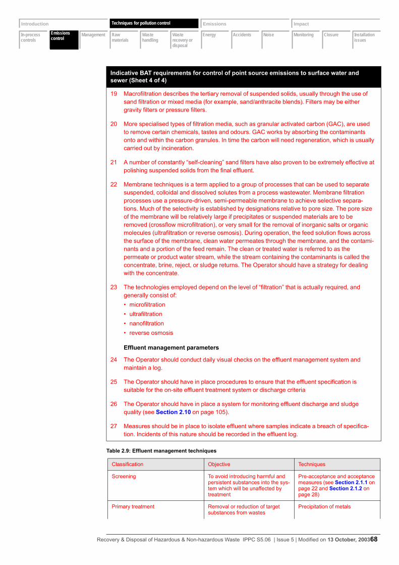
In-process controls
Emissions controls
Management Raw materials
Waste handling
Waste recovery or disposal
Energy Accidents Noise Monitoring Closure Installation issues
Introduction Techniques Emissions Impact
Emissions control
Techniques for pollution control
19 Macrofiltration describes the tertiary removal of suspended solids, usually through the use of sand filtration or mixed media (for example, sand/anthracite blends). Filters may be either gravity filters or pressure filters.
20 More specialised types of filtration media, such as granular activated carbon (GAC), are used to remove certain chemicals, tastes and odours. GAC works by absorbing the contaminants onto and within the carbon granules. In time the carbon will need regeneration, which is usually carried out by incineration.
21 A number of constantly “self-cleaning” sand filters have also proven to be extremely effective at polishing suspended solids from the final effluent.
22 Membrane techniques is a term applied to a group of processes that can be used to separate suspended, colloidal and dissolved solutes from a process wastewater. Membrane filtration processes use a pressure-driven, semi-permeable membrane to achieve selective separa-tions. Much of the selectivity is established by designations relative to pore size. The pore size of the membrane will be relatively large if precipitates or suspended materials are to be removed (crossflow microfiltration), or very small for the removal of inorganic salts or organic molecules (ultrafiltration or reverse osmosis). During operation, the feed solution flows across the surface of the membrane, clean water permeates through the membrane, and the contami-nants and a portion of the feed remain. The clean or treated water is referred to as the permeate or product water stream, while the stream containing the contaminants is called the concentrate, brine, reject, or sludge returns. The Operator should have a strategy for dealing with the concentrate.
23 The technologies employed depend on the level of “filtration” that is actually required, and generally consist of:• microfiltration• ultrafiltration• nanofiltration• reverse osmosis
Effluent management parameters
24 The Operator should conduct daily visual checks on the effluent management system and maintain a log.
25 The Operator should have in place procedures to ensure that the effluent specification is suitable for the on-site effluent treatment system or discharge criteria
26 The Operator should have in place a system for monitoring effluent discharge and sludge quality (see Section 2.10 on page 105).
27 Measures should be in place to isolate effluent where samples indicate a breach of specifica-tion. Incidents of this nature should be recorded in the effluent log.
Table 2.9: Effluent management techniques
Classification Objective Techniques
Screening To avoid introducing harmful and persistent substances into the sys-tem which will be unaffected by treatment
Pre-acceptance and acceptance measures (see Section 2.1.1 on page 22 and Section 2.1.2 on page 28)
Primary treatment Removal or reduction of target substances from wastes
Precipitation of metals
Indicative BAT requirements for control of point source emissions to surface water and sewer (Sheet 4 of 4)
Recovery & Disposal of Hazardous & Non-hazardous Waste IPPC S5.06 | Issue 5 | Modified on 13 October, 200368
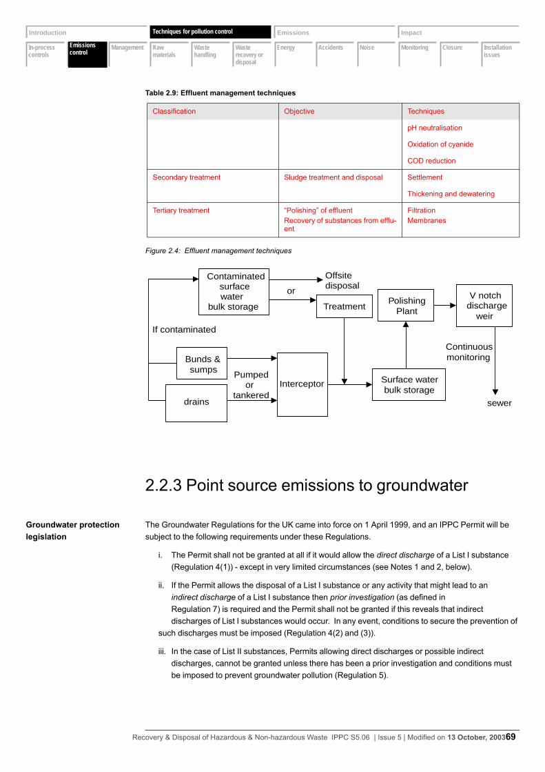
In-process controls
Emissions controls
Management Raw materials
Waste handling
Waste recovery or disposal
Energy Accidents Noise Monitoring Closure Installation issues
Introduction Techniques Emissions Impact
Emissions control
Techniques for pollution control
Figure 2.4: Effluent management techniques
2.2.3 Point source emissions to groundwater
Groundwater protection legislation
The Groundwater Regulations for the UK came into force on 1 April 1999, and an IPPC Permit will be subject to the following requirements under these Regulations.
i. The Permit shall not be granted at all if it would allow the direct discharge of a List I substance (Regulation 4(1)) - except in very limited circumstances (see Notes 1 and 2, below).
ii. If the Permit allows the disposal of a List I substance or any activity that might lead to anindirect discharge of a List I substance then prior investigation (as defined inRegulation 7) is required and the Permit shall not be granted if this reveals that indirectdischarges of List I substances would occur. In any event, conditions to secure the prevention of
such discharges must be imposed (Regulation 4(2) and (3)).
iii. In the case of List II substances, Permits allowing direct discharges or possible indirectdischarges, cannot be granted unless there has been a prior investigation and conditions mustbe imposed to prevent groundwater pollution (Regulation 5).
pH neutralisation
Oxidation of cyanide
COD reduction
Secondary treatment Sludge treatment and disposal Settlement
Thickening and dewatering
Tertiary treatment “Polishing” of effluentRecovery of substances from efflu-ent
FiltrationMembranes
Table 2.9: Effluent management techniques
Classification Objective Techniques
or
If contaminated
Pumpedor
tankered
Bunds &sumps
PolishingPlant
Interceptor Surface waterbulk storage
V notchdischarge
weir
sewer
Continuousmonitoring
Contaminated surface
waterbulk storage
drains
Offsitedisposal
Treatment
Recovery & Disposal of Hazardous & Non-hazardous Waste IPPC S5.06 | Issue 5 | Modified on 13 October, 200369
In-process controls
Emissions controls
Management Raw materials
Waste handling
Waste recovery or disposal
Energy Accidents Noise Monitoring Closure Installation issues
Introduction Techniques Emissions Impact
Emissions control
Techniques for pollution control
iv. The Regulations contain further detailed provisions covering surveillance of groundwater(Regulation 8); conditions required when direct discharges are permitted (Regulation 9); whenindirect discharges are permitted (Regulation 10); and review periods and compliance(Regulation 11).
The principles, powers and responsibilities for groundwater protection in England and Wales, together with the Environment Agency’s policies on this, are outlined in the Environment Agency’s document Policy and Practice for the Protection of Groundwater. This outlines the concepts of vulnerability and risk and the likely acceptability from the Regulator’s viewpoint of certain activities within groundwater protection zones. These are categorised as:
A Prior investigation of the potential effect on groundwater of on-site disposal activities ordischarges to groundwater. Such investigations will vary from case to case, but the Regulator is likely to require a map of the proposed disposal area; a description of the underlying geology, hydrogeology and soil type, including the depth of saturated zone and quality of groundwater; the proximity of the site to any surface waters and abstraction points, and the relationship between ground and surface waters; and the composition and volume of waste to be disposedof; and the rate of planned disposal.
The Environment Agency has produced a series of maps for England and Wales, which provide a guide to potential groundwater vunerability. Source Protection Zones are intended to aid protection by defining annular zones around each major potable source, including springs, boreholes and wells, based on travel times.
B Surveillance - This will also vary from case to case, but will include monitoring of groundwater quality and ensuring the necessary precautions to prevent groundwater pollution are being undertaken.
Note 1 The Regulations state that, subject to certain conditions, the discharges of List Isubstances to groundwater may be authorised if the groundwater is “permanentlyunsuitable for other uses”. Advice must be sought from the Regulator where this is beingconsidered as a justification for such discharges.
Note 2 List I and List II refer to the list in the Groundwater Regulations and should not beconfused with the similar lists in the Dangerous Substances Directive (see Appendix 3)
2.2.4 Fugitive emissions to air
Fugitives Examples of common sources of fugitive emissions are:• open vessels (for example, the effluent treatment plant)• sampling activities
Indicative BAT requirements for Application Question B2.4 Identify if there may be a discharge of any List I or List II substances and if any are identified, explain how the requirements of the Groundwater Regulations 1998 have been addressed.
1 In general, there should be no permitted releases to groundwater of either a direct or indirect nature.
2 If there are releases to groundwater and they are to continue, the requirements of the Regula-tions, as summarised above, must be complied with.
Recovery & Disposal of Hazardous & Non-hazardous Waste IPPC S5.06 | Issue 5 | Modified on 13 October, 200370
In-process controls
Emissions controls
Management Raw materials
Waste handling
Waste recovery or disposal
Energy Accidents Noise Monitoring Closure Installation issues
Introduction Techniques Emissions Impact
Emissions control
Techniques for pollution control
• storage areas (for example, bays, stockpiles, lagoons, etc.)• the loading and unloading of containers• transferring/bulking up of material from one vessel to another• conveyor systems• pipework and ductwork systems (for example, pumps, valves, flanges, catchpots, drains, inspection
hatches, etc.)• poor building containment and extraction• potential for by-pass of abatement equipment (to air or water)• spillages• accidental loss of containment from failed plant and equipment• tanker and vessels manhole openings and other access points• displaced vapour in receiving tanks• cleaning or replacing of filters• drum cutting• wastewater storage• drum storage• tank cleaning• tanker washing
As part of the Application the Operator should identify and, where possible quantify, significant fugitive emissions to air from all the specific relevant sources listed above, estimating the proportion of total emissions that are attributable to fugitive releases for each substance. Where there are opportunities for reductions, the Permit may require the updated inventory of fugitive emissions to be submitted.
Indicative BAT requirements for control of fugitive emissions to air
1 Dust - The following general techniques should be employed where appropriate:• Covering of skips and vessels• Avoidance of outdoor or uncovered stockpiles (where possible)• Where dust creation is unavoidable, use of sprays, binders, stockpile management tech-
niques, windbreaks and so on• Regular wheel and road cleaning (avoiding transfer of pollution to water and wind blow)• Closed conveyors, pneumatic or screw conveying (noting the higher energy needs), minimis-
ing drops. Filters on the conveyors to clean the transport air prior to release• Regular housekeeping• Enclosed silos (for storage of bulk powder materials) vented to fabric filters. The recycling of
collected material should be considered under Section 2.6.• Enclosed containers or sealed bags used for smaller quantities of fine materials
2 VOCs• When transferring volatile liquids, the following techniques should be employed – subsurface
filling via (anti-syphon) filling pipes extended to the bottom of the container, the use of vapour balance lines that transfer the vapour from the container being filled to the one being emp-tied, or an enclosed system with extraction to suitable abatement plant.
• Vent systems should be chosen to minimise breathing emissions (for example pressure/ vac-uum valves) and, where relevant, should be fitted with knock-out pots and appropriate abate-ment equipment.
• Maintenance of bulk storage temperatures as low as practicable, taking into account changes due to solar heating etc.
Recovery & Disposal of Hazardous & Non-hazardous Waste IPPC S5.06 | Issue 5 | Modified on 13 October, 200371

In-process controls
Emissions controls
Management Raw materials
Waste handling
Waste recovery or disposal
Energy Accidents Noise Monitoring Closure Installation issues
Introduction Techniques Emissions Impact
Emissions control
Techniques for pollution control
2.2.5 Fugitive emissions to surface water, sewer and groundwater
Fugitives As part of the Application, the Operator should identify and, where possible, quantify significant fugitive emissions to water, sewer or ground from all relevant sources, and estimate the proportion of total emissions that are attributable to fugitive releases for each of the main substances releases.
Some common examples of sources of fugitive releases to waters and their preventive measures are given in the BAT box below.
• The following techniques should be used (together or in any combination) to reduce losses from storage tanks at atmospheric pressure:– Tank paint with low solar absorbency– Temperature control– Tank insulation– Inventory management– Floating roof tanks– Bladder roof tanks– Pressure/vacuum valves, where tanks are designed to withstand pressure fluctuations– Specific release treatment (such as adsorption condensation)
3 For Information on Odour, see Section 2.2.6 on page 79.
4 A leak detection and repair (LDAR) programme should be established for installations handling solvents and similar volatile materials. In addition:• Non-intrusive tank volume measurements should be used.• When cleaning filters, filter pot lids should be replaced as soon as possible.• Filter slops should be stored in sealed drums.• Contaminated waters have potential for odours and should be stored in covered tanks.• Drum storage (see Section 2.1.3 on page 36).• Maintenance schedules should ensure regular cleaning/desludging of tanks to avoid large
scale decontamination activities.• Tanker washing should be conducted under a permit to work scheme. If the load is likely to
give rise to odour, then the first wash should be with water/aqueous waste and discharged direct to abated storage systems before opening the tanker manways. Open tanker barrel for the minimum amount of time. All washings to be directed to abated storage systems.
Indicative BAT requirements for control of fugitive emissions to air
Indicative BAT requirements for control of fugitive emissions to Water (Sheet 1 of 3)
1 For subsurface structures:• establish and record the routing of all installation drains and subsurface pipework;• identify all sub-surface sumps and storage vessels;• engineer systems to minimise leakages from pipes and ensure swift detection if they do
occur, particularly where hazardous (ie. Groundwater-listed) substances are involved;• provide secondary containment and/or leakage detection for sub-surface pipework, sumps
and storage vessels;
Recovery & Disposal of Hazardous & Non-hazardous Waste IPPC S5.06 | Issue 5 | Modified on 13 October, 200372
In-process controls
Emissions controls
Management Raw materials
Waste handling
Waste recovery or disposal
Energy Accidents Noise Monitoring Closure Installation issues
Introduction Techniques Emissions Impact
Emissions control
Techniques for pollution control
• establish an inspection and maintenance programme for all subsurface structures, eg. pres-sure tests, leak tests, material thickness checks or CCTV
2 All sumps should:• be impermeable and resistant to stored materials;• be subject to regular visual inspection and any contents pumped out or otherwise removed
after checking for contamination;• where not frequently inspected, be fitted with a high level probe and alarm, as appropriate;• be subject to programmed engineering inspection (normally visual, but extending to water
testing where structural integrity is in doubt).
3 For surfacing:• design appropriate surfacing and containment or drainage facilities for all operational areas,
taking into consideration collection capacities, surface thicknesses, strength/reinforcement; falls, materials of construction, permeability, resistance to chemical attack, and inspection and maintenance procedures;
• have an inspection and maintenance programme for impervious surfaces and containment facilities;
• unless the risk is negligible, have improvement plans in place where operational areas have not been equipped with:– an impervious surface– spill containment kerbs– sealed construction joints– connection to a sealed drainage system
4 All above-ground tanks containing liquids whose spillage could be harmful to the environ-ment should be bunded. For further information on bund sizing and design, see the Releases to water references. Bunds should:• be impermeable and resistant to the stored materials;• have no outlet (that is, no drains or taps) and drain to a blind collection point;• have pipework routed within bunded areas with no penetration of contained surfaces;• be designed to catch leaks from tanks or fittings;• have a capacity greater than 110 percent of the largest tank or 25 percent of the total tank-
age, whichever is the larger;• be subject to regular visual inspection and any contents pumped out or otherwise removed
under manual control after checking for contamination;• where not frequently inspected, be fitted with a high-level probe and an alarm, as appropri-
ate;• where possible, have tanker conection points within the bund, otherwise provide adequate
containment;• be subject to programmed engineering inspection (normally visual, but extending to water
testing where structural integrity is in doubt).
5 Storage areas for IBCs, drums, bags, etc, should be designed and operated to minimise the risk of releases to the environment. In particular:• Storage areas should be located away from watercourses and sensitive boundaries, (eg.
those with public access) and should be protected against vandalism.• Storage areas should have appropriate signs and notices and be clearly marked-out, and all
containers and packages should be clearly labelled.• The maximum storage capacity of storage areas should be stated and not exceeded, and the
maximum storage period for containers should be specified and adhered to.
Indicative BAT requirements for control of fugitive emissions to Water (Sheet 2 of 3)
Recovery & Disposal of Hazardous & Non-hazardous Waste IPPC S5.06 | Issue 5 | Modified on 13 October, 200373
In-process controls
Emissions controls
Management Raw materials
Waste handling
Waste recovery or disposal
Energy Accidents Noise Monitoring Closure Installation issues
Introduction Techniques Emissions Impact
Emissions control
Techniques for pollution control
2.2.6 Odour
The level of detail supplied should be in keeping with the risk of causing odour-related annoyance at sensitive receptors.
Where an installation poses no risk of odour-related environmental impact because the activities undertaken are inherently non-odorous, this should be justified and no further information relating to odour need normally be supplied.
Where odour could be a problem, the Operator will be required in the Application to supply the information as indicated below:• Information relating to sensitive receptors, in particular the type of receptor, location relative to the
odour sources and an assessment of the impact of odorous emissions on the receptors. Where detailed information is required the Operator may be able to secure an agreement to supply this as part of an Improvement Programme.
• An overview of any complaints received, what they relate to (source/operation) and remedial action taken.
• The types and source of odorous substances used or generated, intentional and fugitive (uninten-tional) release points and monitoring undertaken.
• Actions taken to prevent or minimise– A description of the actions taken to prevent and/or minimise odour annoyance for each odour
source.– A demonstration that the indicative BAT requirements are being complied with.– Identification of any circumstances or conditions which might compromise the ability to prevent or
minimise odour annoyance, and a description of the actions that will be taken to minimise the impact.
There may be a requirement placed upon the Operator to provide some or all of this information in the form of an odour management statement. See the Odour management statement for a typical log book.
The definition of pollution includes “emissions which may be harmful to human health or the quality of the environment, cause offence to human senses or impair or interfere with amenities and other legitimate uses of the environment”. Odour emissions can constitute “offence to human senses” and are associated with point sources (see Section 2.2.1 on page 64) as well as fugitive sources (see Section 2.2.4 on page 76).
Further guidance on odour can be found at Integrated Pollution Prevention and Control (IPPC) IPPC Horizontal Guidance Note for Odour - H4: Parts 1 and 2
• Appropriate storage facilities should be provided for substances with special requirements (eg. flammable, sensitive to heat or light) and formal arrangements should be in hand to keep separate packages containing incompatible substances (both “pure” and waste).
• Containers should be stored with lids, caps and valves secured and in place - and this also applies to emptied containers.
• All stocks of containers, drums and small packages should be regularly inspected (at least weekly).
• Procedures should be in place to deal with damaged or leaking containers.
Indicative BAT requirements for control of fugitive emissions to Water (Sheet 3 of 3)
Recovery & Disposal of Hazardous & Non-hazardous Waste IPPC S5.06 | Issue 5 | Modified on 13 October, 200374
In-process controls
Emissions controls
Management Raw materials
Waste handling
Waste recovery or disposal
Energy Accidents Noise Monitoring Closure Installation issues
Introduction Techniques Emissions Impact
Emissions control
Techniques for pollution control
Indicative BAT requirements for Odour control
1 The requirements for odour control will be installation-specific and depend on the sources and nature of the potential odour. In general:
2 Where odour can be contained, for example within buildings, the Operator should maintain the containment and manage the operations to prevent its release at all times.
3 Where odour releases are expected to be acknowledged in the Permit, (i.e. contained and treated prior to discharge or discharged for atmospheric dispersion):• For existing installations, the releases should be modelled to demonstrate the odour impact
at sensitive receptors. The target should be to minimise the frequency of exposure to ground level concentrations that are likely to cause annoyance.
• For new installations, or for significant changes, the releases should be modelled and it is expected that the Operator will achieve the highest level of protection that is achievable with BAT from the outset.
• Where there is no history of odour problems then modelling may not be required although it should be remembered that there can still be an underlying level of annoyance without com-plaints being made.
• Where, despite all reasonable steps in the design of the plant, extreme weather or other inci-dents are liable, in the view of the Regulator, to increase the odour impact at receptors, the Operator should take appropriate and timely action, as agreed with the Regulator, to prevent further annoyance (these agreed actions will be defined either in the Permit or in an odour management statement).
4 Where odour generating activities take place in the open, (or potentially odorous materials are stored outside) a high level of management control and use of best practice will be expected.
5 Where an installation releases odours but has a low environmental impact by virtue of its remoteness from sensitive receptors, it is expected that the Operator will work towards achieving the standards described in this Note, but the timescales allowed to achieve this might be adjusted according to the perceived risk.
6 The objective is to prevent emissions of odorous releases that are offensive and detectable beyond the site boundary. This may be judged by the likelihood of complaints. However, the lack of complaint should not necessarily imply the absence of an odour problem.
7 Assessment of odour impact should cover a range of reasonably foreseeable odour generation and receptor exposure scenarios, including emergency events and the effect of different mitiga-tion options.
8 For complex installations, for example where there are a number of potential sources of odorous releases or where there is an extensive programme of improvements to bring odour under control, an odour management plan should be maintained.
9 Emphasis should be placed on pre-acceptance screening (see Section 2.1.1 on page 22) and the rejection of specific wastes, for example, mercaptans, low molecular weight amines, acrylates or other similarly highly odorous materials, that are only suitable for acceptance under special handling requirements. These may include dedicated sealed handling areas with extraction to abatement.
10 Scrubber liquors should be monitored to ensure optimum performance, i.e. correct pH, replen-ishment and replacement.
Recovery & Disposal of Hazardous & Non-hazardous Waste IPPC S5.06 | Issue 5 | Modified on 13 October, 200375
In-process controls
Emissions controls
Management Raw materials
Waste handling
Waste recovery or disposal
Energy Accidents Noise Monitoring Closure Installation issues
Introduction Techniques Emissions Impact
Management
Techniques for pollution control
2.3 Management
Within IPPC, an effective system of management is a key technique for ensuring that all appropriate pollution prevention and control techniques are delivered reliably and on an integrated basis.
The Regulators strongly support the operation of formal environmental management systems (EMSs). An Operator with such a system will not only find it easier to meet the BAT requirements for management of the installation but also many of the technical/regulatory requirements listed in other Sections of this Guidance.
The Regulators recommend either certification to the ISO 14001 standard or registration under EMAS (EC Eco Management and Audit Scheme) (OJ L114, 24/04/01). Both certification and registration provide independent verification that the EMS conforms to an auditable standard. EMAS now incorporates ISO 14001 as the specification for the EMS element, and the Regulators consider that overall EMAS has a number of other benefits over ISO14001 - including a greater focus on environmental performance, a greater emphasis on legal compliance, and a public environmental statement. For further details about ISO 14001 and EMAS contact British Standards Institute (BSI) or the Institute of Environmental Management and Assessment (IEMA), respectively.
Whilst an effective EMS will help the Operator to maintain compliance with specific regulatory requirements and manage all significant environmental impacts, this section of the Guidance identifies only those EMS requirements that are not specifically covered elsewhere in the document. This Section should not, therefore, be taken to describe all of the elements of an effective environmental management system. The requirements below are considered to be BAT for IPPC, but they are the same techniques required by a formal EMS and so should be capable of delivering wide environmental benefits.
The European Commission has also set out its views on BAT and Environmental Management Systems in the form of standard text which will be included in all new and updated BREFs.
It is a requirement that the management of the installation site is controlled by a person who is a “fit and proper person”. This includes a component whereby the management of the Specified Waste Management Activity (SWMA) that is to be carried out is in the hands of Technically Competent Management (TCM).
Indicative BAT requirements for management (Sheet 1 of 3)
Operations and maintenance
11 Effective operational and maintenance systems should be employed on all aspects of the process whose failure could impact on the environment, in particular there should be:• documented procedures to control operations that may have an adverse impact on
the environment• a defined procedure for identifying, reviewing and prioritising items of plant for which a
preventative maintenance regime is appropriate• documented procedures for monitoring emissions or impacts• a preventative maintenance programme covering all plant, whose failure could lead to
impact on the environment, including regular inspection of major ‘non productive’ items such as tanks, pipework, retaining walls, bunds ducts and filters
12 The maintenance system should include auditing of performance against requirements arising from the above and reporting the result of audits to top management.
Recovery & Disposal of Hazardous & Non-hazardous Waste IPPC S5.06 | Issue 5 | Modified on 13 October, 200376

In-process controls
Emissions controls
Management Raw materials
Waste handling
Waste recovery or disposal
Energy Accidents Noise Monitoring Closure Installation issues
Introduction Techniques Emissions Impact
Management
Techniques for pollution control
Competence and training
13 Training systems, covering the following items, should be in place for all relevant staff which cover • awareness of the regulatory implications of the Permit for the activity and their work
activities;• awareness of all potential environmental effects from operation under normal and
abnormal circumstances • awareness of the need to report deviation from the Permit • prevention of accidental emissions and action to be taken when accidental emissions
occur
14 The skills and competencies necessary for key posts should be documented and records of training needs and training received for these post maintained.
15 The key posts should include contractors and those purchasing equipment and materials;
16 The potential environmental risks posed by the work of contractors should be assessed and instructions provided to contractors about protecting the environment while working on site.
17 Where industry standards or codes of practice for training exist (e.g. WAMITAB) they should be complied with.
Accidents/incidents/non-conformance
18 There should be an accident plan as described in Section 2.8 on page 96 which:• identifies the likelihood and consequence of accidents • identifies actions to prevent accidents and mitigate any consequences
19 There should be written procedures for handling, investigating, communicating and reporting actual or potential non-compliance with operating procedures or emission limits.
20 There should be written procedures for handling, investigating, communicating and reporting environmental complaints and implementation of appropriate actions.
21 There should be written procedures for investigating incidents, (and near misses) including identifying suitable corrective action and following up
Organisation
22 The following are indicators of good performance which may impact on the Regulator’s resources, but not all will necessarily be insisted upon as Permit conditions:
23 The company should adopt an environmental policy and programme which:• includes a commitment to continual improvement and prevention of pollution;• includes a commitment to comply with relevant legislation and other requirements to
which the organisation subscribes; and• identifies, sets, monitors and reviews environmental objectives and key performance
indicators independently of the Permit.
Indicative BAT requirements for management (Sheet 2 of 3)
Recovery & Disposal of Hazardous & Non-hazardous Waste IPPC S5.06 | Issue 5 | Modified on 13 October, 200377
In-process controls
Emissions controls
Management Raw materials
Waste handling
Waste recovery or disposal
Energy Accidents Noise Monitoring Closure Installation issues
Introduction Techniques Emissions Impact
Management
Techniques for pollution control
24 The company should have demonstrable procedures (eg. written instructions) which incorporate environmental considerations into the following areas:• the control of process and engineering change on the installation; • design, construction and review of new facilities and other capital projects (including
provision for their decommissioning);• capital approval; and• purchasing policy.
25 The company should conduct audits, at least annually, to check that all activities are being carried out in conformity with the above requirements. Preferably, these should be independent.
26 The company should report annually on environmental performance, objectives and targets, and future planned improvements. Preferably, these should be published envi-ronmental statements.
27 The company should operate a formal Environmental Management System. Prefer-ably, this should be a registered or certified EMAS/ISO 14001 system (issued and audited by an accredited certification body).
28 The company should have a clear and logical system for keeping records of, amongst others:• policies• roles and responsibilities• targets• procedures• results of audits• results of reviews
Indicative BAT requirements for management (Sheet 3 of 3)
Recovery & Disposal of Hazardous & Non-hazardous Waste IPPC S5.06 | Issue 5 | Modified on 13 October, 200378
In-process controls
Emissions controls
Management Raw materials
Waste handling
Waste recovery or disposal
Energy Accidents Noise Monitoring Closure Installation issues
Introduction Techniques Emissions Impact
Raw materials
Techniques for pollution control
2.4 Raw materials
This section covers the use of raw materials and water, and the techniques for both minimising their use and minimising their impact by selection. (Energy and fuels are covered under Section 2.7 on page 92, Energy).
As a general principle, the Operator will need to demonstrate the measures taken to:• reduce the usage of all raw materials and intermediates ( Section 2.4.2 on page 87)• substitute less harmful materials, or those which can be more readily abated and when abated lead
to substances that are more readily dealt with• understand the fate of by-products and contaminants and their environmental impact ( Section
2.4.2 on page 87)
2.4.1 Raw materials selection
This section looks at the selection and substitution of raw materials and Section 2.4.2 on page 87 describes the techniques to minimise their use.
It should be recognised that the process of selecting raw materials can present an opportunity to control emissions at source. In this regard it is suggested that Operators closely examine the range of possible raw material options available to them.
The Operator should supply in the Application a list of the materials used which have potential for significant environmental impact, together with the following associated information:• the chemical composition of the materials, where relevant;• the quantities used; • the fate of the material in the installation (ie. approximate percentages to each environmental
medium and to the products); • the environmental impact potential, where known (eg. degradability, bioaccumulation potential, tox-
icity to relevant species);• any reasonably practicable alternative raw materials that may have a lower environmental impact
(including, but not limited to any alternatives described in the BAT requirements below ) on the sub-stitution principle;
• and justification for the continued use of any substance for which there is a less hazardous alterna-tive (eg. on the basis of impact on product quality) to show that the proposed raw materials are therefore BAT.
Recovery & Disposal of Hazardous & Non-hazardous Waste IPPC S5.06 | Issue 5 | Modified on 13 October, 200379

In-process controls
Emissions controls
Management Raw materials
Waste handling
Waste recovery or disposal
Energy Accidents Noise Monitoring Closure Installation issues
Introduction Techniques Emissions Impact
Raw materials
Techniques for pollution control
The proportion of raw materials (i.e. purchased reagents) used is relatively low and in the first instance wastes are used to treat wastes. However, raw materials are used and Table 2.10 summarises their use.
Consideration has been given to utilising spent lime from incinerator lime injection acid gas abatement systems. Purchased lime has a much higher alkalinity than the spent lime and consequently larger volumes are required of the spent lime, which places a limitation in relation to the size of reactor vessel, that is, > 50 t capacity vessels are required. This requires a similar scale-up with mixing tanks to produce the lime solution. Attention should also be given to the level of metal and organic contamination that may be present.
Table 2.10: Examples of raw materials usage
Raw material Application Principal environmental characteristics
WASTE TREATMENT
Calcium hydrox-ide (lime)
Usually purchased in powder form for acid treatment
Hazardous substancePowder difficult to handleProduces large sludge volumesFor example, the treatment of sulphuric acid results in a large net production of calcium sulphate sludge. Treatment costs for concen-trated sulphuric acid may consequently be up to £200/t
Sodium hydroxide (caustic soda) solution
Abatement reagent typically used in wet scrubbing systems to control acid gases and is also used as a scrubbing liquor in oil processing
Hazardous substanceVery low levels of mercury may be found in some grades of caustic soda, which may transfer to effluent leaving the installation
Ferric chloride solution
Additive to aid precipitation of metals and conditioning agent for sludge formation (that is, helps with floc formation)
Strongly coloured in the event of a spillage or incident. No other factors
Sodium hypochlo-rite
Used in treatment and abatement for cyanide wastes scrubbing and odour control
Strong oxidising agent.Must be stored away from potentially incom-patible substancesVery low levels of mercury may be found in some grades of caustic soda, which may transfer to effluent leaving the installation
OIL REPROCESSING
De-emulsifiers To “crack” emulsified oil-water mixtures in oil recovery
High oxygen demand if released to water in the event of an accident
Indicative BAT requirements for raw materials selection
1 The Operator should maintain a list of raw materials and their properties as noted above.
2 The Operator should have procedures for the regular review of new developments in raw materials and for the implementation of any suitable ones with an improved environmental profile.
3 The Operator should have quality-assurance procedures for controlling the impurity content of raw materials.
4 The Operator should complete any longer-term studies needed into the less polluting options and should make any material substitutions identified.
5 The substitutions in Table 2.11 should be employed, where applicable.
Recovery & Disposal of Hazardous & Non-hazardous Waste IPPC S5.06 | Issue 5 | Modified on 13 October, 200380
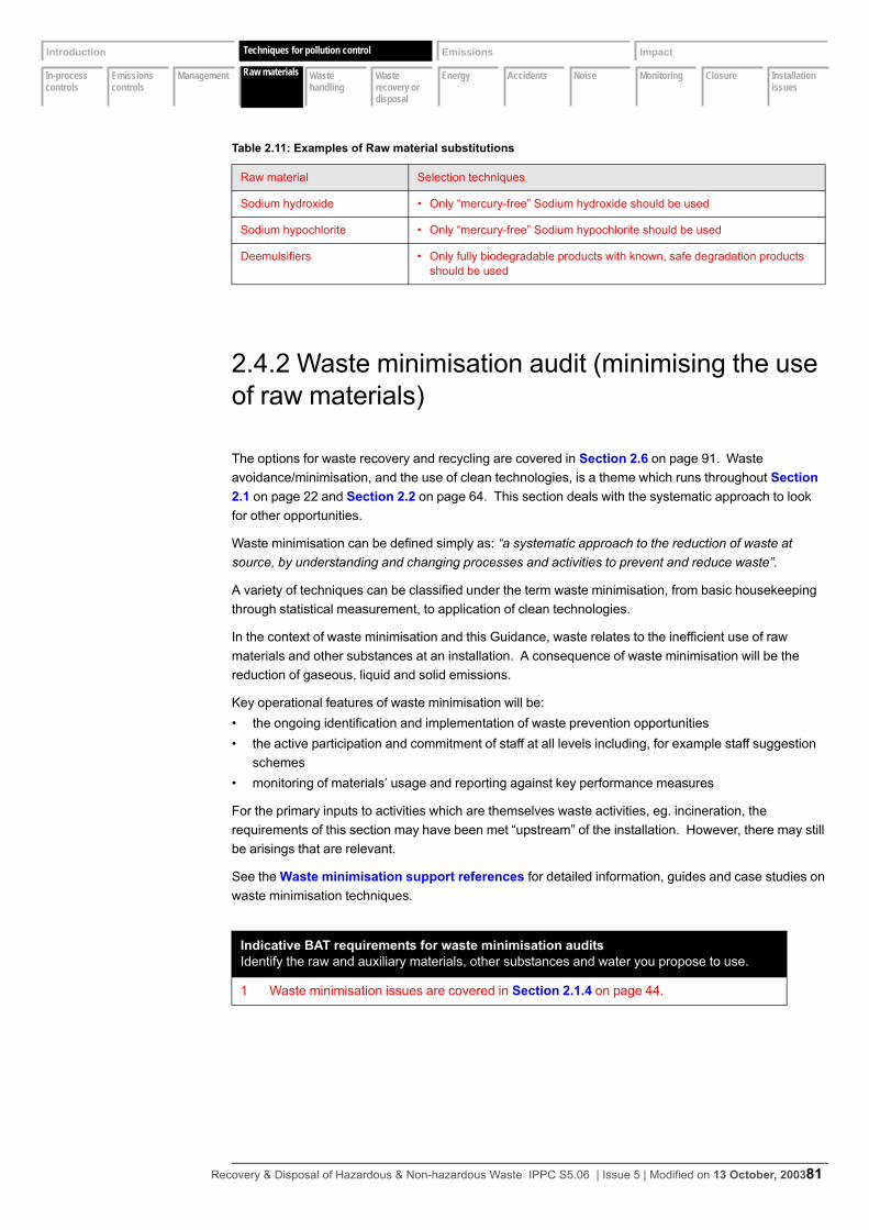
In-process controls
Emissions controls
Management Raw materials
Waste handling
Waste recovery or disposal
Energy Accidents Noise Monitoring Closure Installation issues
Introduction Techniques Emissions Impact
Raw materials
Techniques for pollution control
2.4.2 Waste minimisation audit (minimising the use of raw materials)
The options for waste recovery and recycling are covered in Section 2.6 on page 91. Waste avoidance/minimisation, and the use of clean technologies, is a theme which runs throughout Section 2.1 on page 22 and Section 2.2 on page 64. This section deals with the systematic approach to look for other opportunities.
Waste minimisation can be defined simply as: “a systematic approach to the reduction of waste at source, by understanding and changing processes and activities to prevent and reduce waste”.
A variety of techniques can be classified under the term waste minimisation, from basic housekeeping through statistical measurement, to application of clean technologies.
In the context of waste minimisation and this Guidance, waste relates to the inefficient use of raw materials and other substances at an installation. A consequence of waste minimisation will be the reduction of gaseous, liquid and solid emissions.
Key operational features of waste minimisation will be:• the ongoing identification and implementation of waste prevention opportunities• the active participation and commitment of staff at all levels including, for example staff suggestion
schemes• monitoring of materials’ usage and reporting against key performance measures
For the primary inputs to activities which are themselves waste activities, eg. incineration, the requirements of this section may have been met “upstream” of the installation. However, there may still be arisings that are relevant.
See the Waste minimisation support references for detailed information, guides and case studies on waste minimisation techniques.
Table 2.11: Examples of Raw material substitutions
Raw material Selection techniques
Sodium hydroxide • Only “mercury-free” Sodium hydroxide should be used
Sodium hypochlorite • Only “mercury-free” Sodium hypochlorite should be used
Deemulsifiers • Only fully biodegradable products with known, safe degradation products should be used
Indicative BAT requirements for waste minimisation auditsIdentify the raw and auxiliary materials, other substances and water you propose to use.
1 Waste minimisation issues are covered in Section 2.1.4 on page 44.
Recovery & Disposal of Hazardous & Non-hazardous Waste IPPC S5.06 | Issue 5 | Modified on 13 October, 200381
In-process controls
Emissions controls
Management Raw materials
Waste handling
Waste recovery or disposal
Energy Accidents Noise Monitoring Closure Installation issues
Introduction Techniques Emissions Impact
Raw materials
Techniques for pollution control
2.4.3 Water use
Reasons for reducing water use
Water use should be minimised within the BAT criteria for the prevention or reduction of emissions and be commensurate with the prudent use of water as a natural resource.
Reducing water use is usually a valid environmental (and economic) aim in itself, but any water passing through an industrial process is degraded by the addition of pollutants so there is generally an increase in pollutant load. The benefits to be gained from reducing water input include:• reducing the size of (a new) treatment plant, thereby supporting the BAT cost-benefit justification of
better treatment;• cost savings where water is purchased from or disposed of to another party;• associated benefits within the process such as reduced energy requirements for heating and pump-
ing, and reduced dissolution of pollutants leading in turn to reduced sludge generation in the efflu-ent treatment plant (and consequent disposal costs).
The use of a simple mass balance for water use should help to reveal where reductions can be made.
Advice on cost-effective measures for minimising water can be found in the Water efficiency references:.
Indicative BAT requirements for water efficiency (Sheet 1 of 2)
1 The Operator should carry out a regular review of water use (water efficiency audit) at least every 4 years. If an audit has not been carried out in the 2 years prior to submis-sion of the application and the details made known at the time of the application, then the first audit should take place within 2 years of the issue of the Permit.• Flow diagrams and water mass balances for the activities should be produced. • Water-efficiency objectives should be established, with constraints on reducing water
use beyond a certain level being identified (which usually will be usually installation-specific).
• Water pinch techniques should be used in the more complex situations such as chemical plant, to identify the opportunities for maximising reuse and minimising use of water (see the Water efficiency references:).
2 Within 2 months of completion of the audit, the methodology used should be submitted to the Regulator, together with proposals for a time-tabled plan for implementing water reduction improvements for approval by the Regulator.
3 The following general principles should be applied in sequence to reduce emissions to water:• Water-efficient techniques should be used at source where possible• Water should be recycled within the process from which it issues, by treating it first if
necessary. Where this is not practicable, it should be recycled to another part of the process that has a lower water-quality requirement
• In particular, if uncontaminated roof and surface water cannot be used in the process, it should be kept separate from other discharge streams, at least until after the con-taminated streams have been treated in an effluent treatment system and been sub-ject to final monitoring.
4 Measures should be in place to minimise the risk of contamination of surface waters or groundwater by fugitive releases of liquids or solids (see Section 2.2.5 on page 78).
Recovery & Disposal of Hazardous & Non-hazardous Waste IPPC S5.06 | Issue 5 | Modified on 13 October, 200382
In-process controls
Emissions controls
Management Raw materials
Waste handling
Waste recovery or disposal
Energy Accidents Noise Monitoring Closure Installation issues
Introduction Techniques Emissions Impact
Raw materials
Techniques for pollution control
5 The water-quality requirements associated with each use should be established, and the scope for substituting water from recycled sources identified and input into the improvement plan.
6 Less contaminated water streams, such as cooling waters, should be kept separate from more contaminated streams where there is scope for reuse - though possibly after some form of treatment.
7 Most wastewater streams will however need some form of treatment (see Section 2.2.2 on page 68 for techniques) but for many applications, the best conventional effluent treatment can produces a water that is usable in the process directly or when mixed with fresh water. Though treated effluent quality can vary, it can often be recycled selectively - used when the quality is adequate, discharged when the quality falls below that which the system can tolerate.
8 In particular, the cost of membrane technology continues to reduce, and they can be applied to individual process streams or to the final effluent from the effluent treatment plant, as appropriate. In some applications in some Sectors, they can supplement (or possibly completely replace) the ETP plant so that most water is recyclable and there is a greatly reduced effluent volume. Where the remaining, possibly concentrated, effluent stream is sufficiently small - and particularly where waste heat is available - further treatment by evaporation can lead to zero aqueous effluent. Where appro-priate, the Operator should assess the costs and benefits of using membrane techniques to minimise water usage and effluent discharge.
9 Water usage for cleaning and washing down should be minimised by:• vacuuming, scraping or mopping in preference to hosing down;• reusing wash water (or recycled water) where practicable;• using trigger controls on all hoses, hand lances and washing equipment.
10 Fresh water consumption should be directly measured and recorded regularly at every significant usage point - ideally on a daily basis.
Indicative BAT requirements for water efficiency (Sheet 2 of 2)
Recovery & Disposal of Hazardous & Non-hazardous Waste IPPC S5.06 | Issue 5 | Modified on 13 October, 200383

In-process controls
Emissions controls
Management Raw materials
Waste handling
Waste recovery or disposal
Energy Accidents Noise Monitoring Closure Installation issues
Introduction Techniques Emissions Impact
Waste handling
Techniques for pollution control
2.5 Waste handling
A waste tracking system should begin at the pre-acceptance stage. With every enquiry a record should be raised (given a unique reference number) which, if the waste disposal enquiry results in waste arriving at site, should “follow” the waste during its acceptance, checking, storage, treatment or removal off-site. If the waste is a regular arising, then the document should be unique to that waste stream. Further details of the requirements of the tracking system are given in Section 2.1.2 on page 28 and Section 2.1.3 on page 36.
The normal nature and source of the waste from each activity is given in Section 2.1 on page 22 and will be confirmed in some detail in the Operator’s response to the emissions inventory.
Recovery & Disposal of Hazardous & Non-hazardous Waste IPPC S5.06 | Issue 5 | Modified on 13 October, 200384
In-process controls
Emissions controls
Management Raw materials
Waste handling
Waste recovery or disposal
Energy Accidents Noise Monitoring Closure Installation issues
Introduction Techniques Emissions Impact
Waste recoveryor disposal
Techniques for pollution control
2.6 Waste recovery or disposal
The Regulations require the Regulator, in setting Permit conditions, to take account of certain general principles, including that the installation in question should be operated in such a way that “waste production is avoided in accordance with Council Directive 75/442/EEC on waste; and where waste is produced it is recovered, or where this is technically or economically impossible it is disposed of, while avoiding or reducing the impact on the environment”. The objectives of the National Waste Strategies should also be considered.
Waste avoidance (minimisation) at source is addressed in detail in Section 2.1 on page 22 and related issues are addressed in the sections on abatement techniques (see Section 2.2 on page 64). The specific requirement for a waste minimisation audit is noted in Section 2.4.2 on page 88.
To meet these requirements, Operators should provide the Regulator with the information requested in point 2 below.
Indicative BAT requirements for waste recovery or disposal Describe how each waste stream is proposed to be recovered or disposed of. If you propose any disposal, explain why recovery is technically and economically impossible and describe the meas-ures planned to avoid or reduce any impact on the environment.
1 Waste should be recovered, unless it is technically or economically impractical to do so.
2 Where waste must be disposed of, the Operator should provide a detailed assessment identi-fying the best environmental options for waste disposal - unless the Regulator agrees that this is unnecessary. For existing disposal activities, this assessment may be carried out as an improvement condition to a timescale to be approved by the Regulator.
Filter cake
3 The filter cake arising from the treatment of acidic and alkali solutions and metal precipitation can contain percentage levels of metals such as zinc and copper. Dry solids content should not be less than 15% w/w to facilitate handling (see Section 2.1.15 on page 63).
Stabilised sludges (see Section 2.1.15 on page 63).
4 The process feedstock should not include substances such as solvents that could be recov-ered at a subsequent stage by, for example, drying.
Contaminated drums
5 All drums and containers should be drained before transfer to a recycling operation. Undam-aged 205 litre drums and 800 and 1000 litre IBCs should be recovered by cleaning and reconditioning. Damaged containers for which there is no reconditioning market and which have held non-hazardous materials can be released into the secondary metals market.
Recovered oil
6 Where it cannot be recycled, utilisation as secondary fuel oil may be acceptable.
Recovery & Disposal of Hazardous & Non-hazardous Waste IPPC S5.06 | Issue 5 | Modified on 13 October, 200385
In-process controls
Emissions controls
Management Raw materials
Waste handling
Waste recovery or disposal
Energy Accidents Noise Monitoring Closure Installation issues
Introduction Techniques Emissions Impact
Energy
Techniques for pollution control
2.7 Energy
BAT for energy efficiency under the PPC Regulations will be satisfied provided the Operator meets the following conditions:
either• the Operator meets the basic energy requirements in Section 2.7.1 and Section 2.7.2 below and is a
participant to a Climate Change Agreement (CCA) or a Direct Participant Agreement (DPA) within the Emissions Trading Scheme.
or• the Operator meets the basic energy requirements in Section 2.7.1 and Section 2.7.2 below and the
further sector-specific energy requirements in Section 2.7.3 below.
Note that even where a Climate Change Agreement or Direct Participant Agreement is in place, this does not preclude the consideration of energy efficiency (including those identified in Section 2.7.3) as part of an integrated assessment of BAT where they impact on other emissions, e.g. where:• the choice of fuel impacts upon emissions other than carbon, e.g. sulphur in fuel• the minimisation of waste by waste-to-energy does not maximise energy efficiency, e.g. by Com-
bined Heat and Power (CHP)• the most energy-intensive abatement leads to the greatest reduction in other emissions
Further guidance is given in the guidance note H2 Energy efficiency for IPPC.
2.7.1 Basic energy requirements (1)
The BAT requirements of this section are basic low-cost energy standards that apply whether or not a CCA or DPA is in force for the installation.
Indicative BAT requirements for basic energy requirements (2.7.1)Provide a breakdown of the energy consumption and generation by source and the associated envi-ronmental emissions.
1 The Operator should provide annually the energy consumption information, shown in the table below, in terms of delivered energy and also, in the case of electricity, converted to primary energy consumption. For the public electricity supply, a conversion factor of 2.6 should be used. Where applicable, the use of factors derived from on-site heat and/or power generation, or from direct (non-grid) suppliers should be used. In the latter cases, the Operator should provide details of such factors. Where energy is exported from the installation, the Operator should also provide this information. In the application this information should be submitted in the inventory in the H1 software tool and should also supplement this with energy flow informa-tion (such as “Sankey” diagrams or energy balances) showing how the energy is used throughout the process.
Recovery & Disposal of Hazardous & Non-hazardous Waste IPPC S5.06 | Issue 5 | Modified on 13 October, 200386

In-process controls
Emissions controls
Management Raw materials
Waste handling
Waste recovery or disposal
Energy Accidents Noise Monitoring Closure Installation issues
Introduction Techniques Emissions Impact
Energy
Techniques for pollution control
The Energy Efficiency Guidance Note provides an appraisal methodology. If Operators use other appraisal methodologies they should state the method in the Application, and provide evidence that appropriate discount rates, asset life and expenditure (£/t) criteria have been employed.
The energy efficiency plan is required to ensure that the Operator has considered all relevant techniques. However, where a CCA or DPA is in place the Regulator will only enforce implementation of those measures in categories 1-3 above.
*Operator to specify conversion factor of primary source to delivered energy.
2.7.2 Basic energy requirements (2)
The BAT requirements of this section are basic low-cost energy standards that apply whether or not a CCA or DPA is in force for the installation.
2 The Operator should provide the following Specific Energy Consumption (SEC) information. Define and calculate the SEC of the activity (or activities) based on primary energy consump-tion for the products or raw material inputs that most closely match the main purpose or production capacity of the installation. Provide a comparison of SEC against any relevant benchmarks available for the sector. (See BREF and Energy Efficiency Guidance)
3 The Operator should provide associated environmental emissions. This is dealt with in the Operator’s response to the emissions inventory using the H1 software tool.
Table 2.12: Example format for energy efficiency plan
ALL APPLICANTS ONLY APPLICANTS WITHOUT CCA
Energy efficiency measure
CO2 savings (tonnes) EquivalentAnnual Cost (EAC)£k
EAC/CO2 saved£/tonne
Date for imple-mentation
Annual lifetime
Indicative BAT requirements for basic energy requirements (2.7.2) (Sheet 1 of 2)Describe the proposed measures for improvement of energy efficiency.
1 Operating, maintenance and housekeeping measures should be in place in the following areas, where relevant: (Indicative checklists of appropriate measures are provided in Appendix 2 of the guidance note H2 Energy efficiency for IPPC.)• air conditioning, process refrigeration and cooling systems (leaks, seals, temperature con-
trol, evaporator/condenser maintenance)• operation of motors and drives• compressed gas systems (leaks, procedures for use)• steam distribution systems (leaks, traps, insulation)
Indicative BAT requirements for basic energy requirements (2.7.1)Provide a breakdown of the energy consumption and generation by source and the associated envi-ronmental emissions.
Recovery & Disposal of Hazardous & Non-hazardous Waste IPPC S5.06 | Issue 5 | Modified on 13 October, 200387
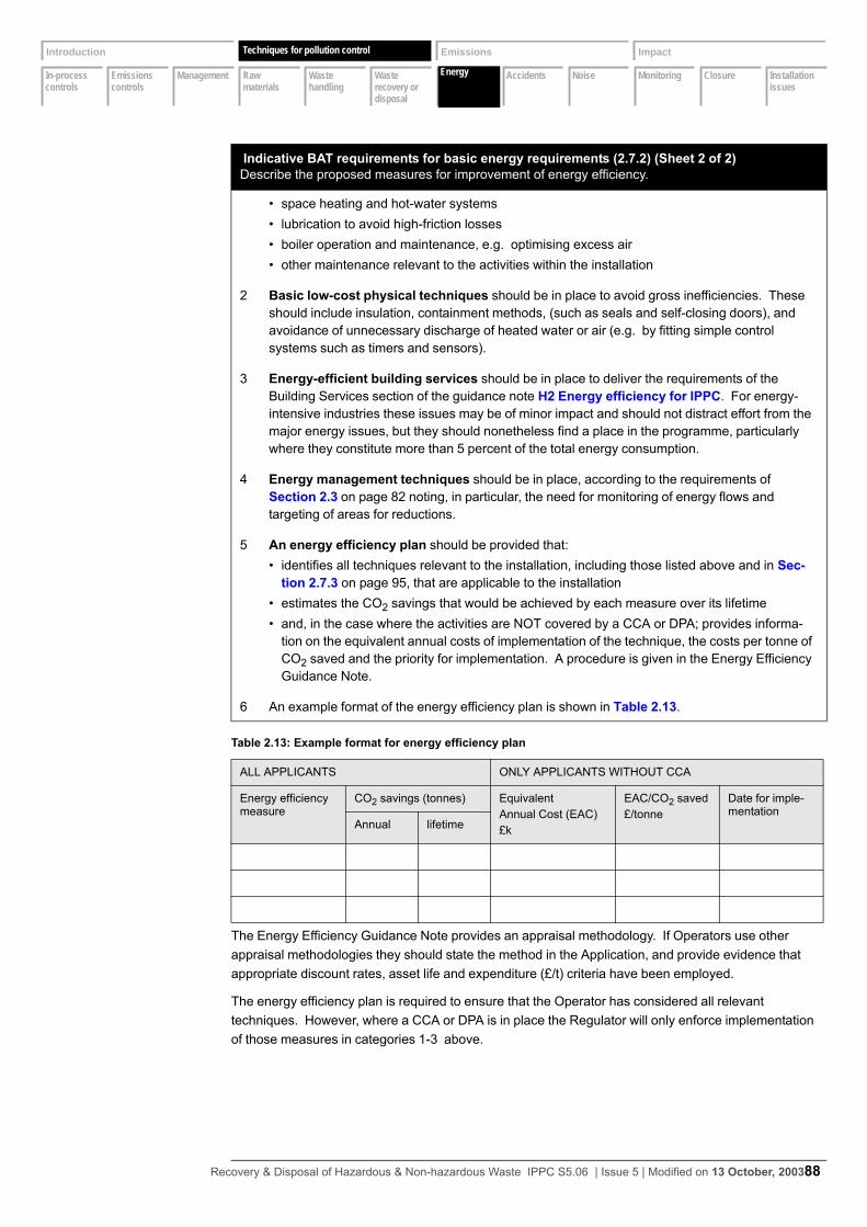
In-process controls
Emissions controls
Management Raw materials
Waste handling
Waste recovery or disposal
Energy Accidents Noise Monitoring Closure Installation issues
Introduction Techniques Emissions Impact
Energy
Techniques for pollution control
The Energy Efficiency Guidance Note provides an appraisal methodology. If Operators use other appraisal methodologies they should state the method in the Application, and provide evidence that appropriate discount rates, asset life and expenditure (£/t) criteria have been employed.
The energy efficiency plan is required to ensure that the Operator has considered all relevant techniques. However, where a CCA or DPA is in place the Regulator will only enforce implementation of those measures in categories 1-3 above.
• space heating and hot-water systems• lubrication to avoid high-friction losses• boiler operation and maintenance, e.g. optimising excess air• other maintenance relevant to the activities within the installation
2 Basic low-cost physical techniques should be in place to avoid gross inefficiencies. These should include insulation, containment methods, (such as seals and self-closing doors), and avoidance of unnecessary discharge of heated water or air (e.g. by fitting simple control systems such as timers and sensors).
3 Energy-efficient building services should be in place to deliver the requirements of the Building Services section of the guidance note H2 Energy efficiency for IPPC. For energy-intensive industries these issues may be of minor impact and should not distract effort from the major energy issues, but they should nonetheless find a place in the programme, particularly where they constitute more than 5 percent of the total energy consumption.
4 Energy management techniques should be in place, according to the requirements of Section 2.3 on page 82 noting, in particular, the need for monitoring of energy flows and targeting of areas for reductions.
5 An energy efficiency plan should be provided that:• identifies all techniques relevant to the installation, including those listed above and in Sec-
tion 2.7.3 on page 95, that are applicable to the installation• estimates the CO2 savings that would be achieved by each measure over its lifetime• and, in the case where the activities are NOT covered by a CCA or DPA; provides informa-
tion on the equivalent annual costs of implementation of the technique, the costs per tonne of CO2 saved and the priority for implementation. A procedure is given in the Energy Efficiency Guidance Note.
6 An example format of the energy efficiency plan is shown in Table 2.13.
Table 2.13: Example format for energy efficiency plan
ALL APPLICANTS ONLY APPLICANTS WITHOUT CCA
Energy efficiency measure
CO2 savings (tonnes) EquivalentAnnual Cost (EAC)£k
EAC/CO2 saved£/tonne
Date for imple-mentation
Annual lifetime
Indicative BAT requirements for basic energy requirements (2.7.2) (Sheet 2 of 2)Describe the proposed measures for improvement of energy efficiency.
Recovery & Disposal of Hazardous & Non-hazardous Waste IPPC S5.06 | Issue 5 | Modified on 13 October, 200388
In-process controls
Emissions controls
Management Raw materials
Waste handling
Waste recovery or disposal
Energy Accidents Noise Monitoring Closure Installation issues
Introduction Techniques Emissions Impact
Energy
Techniques for pollution control
2.7.3 Further energy efficiency requirements
Where there is no CCA or DPA in place, the Operator should demonstrate the degree to which the further energy-efficiency measures identified in the implementation plan, including those below, have been taken into consideration for this sector and justify where they have not.
Indicative BAT requirements for further energy efficiency (2.7.3)Climate Change Agreement or Trading Agreement.
1 The following techniques should be implemented where they are judged to be BAT based on a cost/benefit appraisal according to the methodology provided in Appendix 4 of the Guidance Note H2 Energy efficiency for IPPC.
Energy supply techniques
2 The following techniques should be considered:• use of Combined Heat and Power (CHP)• generation of energy from waste• use of less polluting fuels
3 The Operator should provide justification that the proposed or current situation represents BAT, irrespective of whether or not a CCA or DPA is in place, where there are other BAT considera-tions involved, eg.:• the choice of fuel impacts upon emissions other than carbon dioxide, eg. sulphur dioxide;• the potential for practical energy recovery from waste conflicts with energy efficiency require-
ments.
4 Where there is an on-site combustion plant other guidance is also relevant. For plants greater than 50MW, Operators should consult the IPC guidance on power generation (reference IPC S2 1.01 Combustion Processes: Large boilers and furnaces 50MW(th) and over and supple-ment IPC S3 1.01 Combustion Processes). Operators of plant of 20-50MW should consult the Local Authority Air Pollution Control guidance. On IPPC installations this guidance will be generally applicable to plant under 20MW also. (All are available from the EA website).
Recovery & Disposal of Hazardous & Non-hazardous Waste IPPC S5.06 | Issue 5 | Modified on 13 October, 200389

In-process controls
Emissions controls
Management Raw materials
Waste handling
Waste recovery or disposal
Energy Accidents Noise Monitoring Closure Installation issues
Introduction Techniques Emissions Impact
Accidents
Techniques for pollution control
2.8 Accidents
This section covers accidents and their consequences. It is not limited to major accidents but includes spills and abnormal operation.
Some installations will also be subject to the Control of Major Accident Hazards Regulations 1999 (COMAH) (see Appendix 2 for equivalent legislation in Scotland and Northern Ireland). IPPC and COMAH can sometimes overlap, and some systems and information may be usable for either regime.
The COMAH regime applies to major hazards, and for accident scenarios covered by COMAH , Operators may refer in the Application to any COMAH reports already held by the Regulator. However, the accident provisions under IPPC also cover those which are below the classification threshold for major accidents under COMAH, so Operators need to consider smaller accidents and abnormal operation scenarios as well. Guidance prepared in support of the COMAH Regulations (see the COMAH guides), may also help IPPC Operators in considering ways to reduce the risks and consequences of accidents - whether or not they are covered by the COMAH regime.
General management requirements are covered in Section 2.1 on page 22. For accident management, there are three particular components:• identification of the hazards posed by the installation/activity• assessment of the risks (hazard x probability) of accidents and their possible consequences • implementation of measures to reduce the risks of accidents, and contingency plans for any acci-
dents that do occur
Spillage prevention controls must be in place during the transfer of substances (for example, transfer of bulk liquid waste from tanker to storage vessels) The weakest link and subsequently the main source of spillage during transfer from the vehicle to storage arises from the transfer hoses. This is due to either:
“tanker drive-off” - a vehicle pulling away whilst still coupled (systems should be in place to prevent this) or because the hose couplings have become damaged or are incompatible. Although the spillages tend to be relatively small, measures should be taken to ensure that the couplings are the correct fit and system. This will prevent the coupling loosening or becoming detached, and in turn will also be helped by the installation providing and maintaining its own hoses
Indicative BAT requirements for accidents and abnormal operation (Sheet 1 of 5)Describe your documented system that you proposed (to be used) to identify, assess and minimise the environmental risks and hazards of accidents and their consequences.
1 A formal structured accident management plan should be in place which covers the following aspects:
2 A - Identification of the hazards to the environment posed by the installation using a meth-ology akin to a Hazop study. Areas to consider should include, but should not be limited to, the following:• transfer of substances (eg. filling or emptying of vessels);• overfilling of vessels;• emissions from plant or equipment (eg. leakage from joints, over-pressurisation of vessels,
blocked drains);• failure of containment (eg. physical failure or overfilling of bunds or drainage sumps);• failure to contain firewaters;• wrong connections made in drains or other systems;• incompatible substances allowed to come into contact;• unexpected reactions or runaway reactions;
Recovery & Disposal of Hazardous & Non-hazardous Waste IPPC S5.06 | Issue 5 | Modified on 13 October, 200390
In-process controls
Emissions controls
Management Raw materials
Waste handling
Waste recovery or disposal
Energy Accidents Noise Monitoring Closure Installation issues
Introduction Techniques Emissions Impact
Accidents
Techniques for pollution control
• release of an effluent before adequate checking of its composition;• failure of main services (eg. power, steam, cooling water);• operator error;• vandalism.
3 B - assessment of the risks. The hazards having been identified, the process of assessing the risks should address six basic questions:• how likely is the particular evant to occur (source frequency)?• what substances are released and how much of each (risk evaluation of the event)?• where do the released substances end up (emission prediction - what are the pathways and
receptors)?• what are the consequences (consequence assessment – what are the effects on the recep-
tors)?• what are the overall risks (determination of overall risk and its significance to the environ-
ment)?• what can prevent or reduce the risk (risk management – measures to prevent accidents and/
or reduce their environmental consequences)?
4 The depth and type of assessment will depend on the characteristics of the installation and its location. The main factors to take into account are:• the scale and nature of the accident hazard presented by the installation and the activities• the risks to areas of population and the environment (receptors)• the nature of the installation and complexity of the activities and the relative difficulty in
deciding and justifying the adequacy of the risk-control techniques
5 C - identification of the techniques necessary to reduce the risks. The following tech-niques are relevant to most installations:• there should be an up-to-date inventory of substances, present or likely to be present, which
could have environmental consequences if they escape. This should include apparently innocuous substances that can be environmentally damaging if they escape (for example, a tanker of milk spilled into a watercourse can destroy its ecosystem). The Permit will require the Regulator to be notified of any significant changes to the inventory.
• procedures should be in place for checking and handling raw materials and wastes to ensure compatibility with other substances with which they may accidentally come into contact.
• storage arrangements for raw materials, products and wastes should be designed and oper-ated to minimise risks to the environment.
• there should be automatic process controls backed-up by manual supervision, both to mini-mise the frequency of emergency situations and to maintain control during emergency situa-tions. Instrumentation will include, where appriopriate, microprocessor control, trips and process interlocks, coupled with independent level, temperature, flow and pressure metering and high or low alarms.
• physical protection should be in place where appropriate (eg. barriers to prevent damage to equipment from the movement of vehicles).
• there should be appropriate secondary containment (eg. bunds, catchpots, building contain-ment).
• techniques and procedures should be in place to prevent overfilling of tanks - lliquid or pow-der - (eg. level measurement displayed both locally and at the central control point, inde-pendent high-level alarms, high-level cut-off, and batch metering).
• where the installation is situated in a floodplain, consideration should be given to techniques which will minimise the risk of the flooding causing a pollution incident or making one worse.
Indicative BAT requirements for accidents and abnormal operation (Sheet 2 of 5)Describe your documented system that you proposed (to be used) to identify, assess and minimise the environmental risks and hazards of accidents and their consequences.
Recovery & Disposal of Hazardous & Non-hazardous Waste IPPC S5.06 | Issue 5 | Modified on 13 October, 200391

In-process controls
Emissions controls
Management Raw materials
Waste handling
Waste recovery or disposal
Energy Accidents Noise Monitoring Closure Installation issues
Introduction Techniques Emissions Impact
Accidents
Techniques for pollution control
• security systems to prevent unauthorised access should be provided where appropriate. • there should be formal systems for the logging and recording of all incidents, near-misses,
abnormal events, changes to procedures and significant findings of maintenance inspec-tions.
• there should be procedures for responding to and learning from incidents, near-misses, etc.• the roles and responsibilities of personnel involved in in incident management should be for-
mally specified.• clear guidance should be available on how each accident scenario might best be managed
(eg. containment or dispersion, to extinguish fires or to let them burn).• procedures should be in place to avoid incidents occurring as a result of poor communica-
tions between staff at shift change or during maintenance or other engineering work.• safe shutdown procedures should be in place.• communication channels with emergency services and other relevant authorities should be
established, and available for use in the event of an incident. Procedures should include the assessment of harm following an incident and the steps needed to redress this
• appropriate control techniques should be in place to limit the consequences of an accident, such as isolation of drains, provision of oil spillage equipment, alerting of relevant authorities and evacuation procedures.
• personnel training requirements should be identified and training provided.• the systems for the prevention of fugitive emissions are generally relevant (Section 2.2.4 on
page 75 and Section 2.2.5 on page 78) and in addition, for drainage systems:– procedures should be in place to ensure that the composition of the contents of a bund
sump, or sump connected to a drainage system, are checked before treatment or disposal;– drainage sumps should be equipped with a high-level alarm or with a sensor and auto-
matic pump to storage (not to discharge); – there should be a system in place to ensure that sump levels are kept to a minimum at all
times;– high-level alarms and similar back-up instruments should not be used as the primary
method of level control.• duplicate or standby plant should be provided where necessary, with maintenance and test-
ing to the same standards as the main plant;• spill contingency procedures should be in place to minimise accidental release of raw materi-
als, products and waste materials and then to prevent their entry into water. • process waters, potentially contaminated site drainage waters, emergency firewater, chemi-
cally-contaminated waters and spillages of chemicals should be contained and, where nec-essary, routed to the effluent system and treated before emission to controlled waters or sewer. Sufficient storage should be provided to ensure that this can be achieved. Any emer-gency firewater collection system should take account of the additional firewater flows and fire-fighting foams, and emergency storage lagoons may be needed to prevent contaminated firewater reaching controlled waters (see the Releases to water references).
• consideration should be given to the possibility of containment or abatement of accidental emissions from vents and safety relief valves/bursting discs. Where this may be inadvisable on safety grounds, attention should be focused on reducing the probability of the emission.
• Spillage prevention controls must be in place during the transfer of substances (for example, transfer of bulk liquid waste from tanker to storage vessels)– The weakest link and subsequently the main source of spillage during transfer from the
vehicle to storage arises from the transfer hoses. This is due to either:– “tanker drive-off” - a vehicle pulling away whilst still coupled (systems should be in place to
prevent this)
Indicative BAT requirements for accidents and abnormal operation (Sheet 3 of 5)Describe your documented system that you proposed (to be used) to identify, assess and minimise the environmental risks and hazards of accidents and their consequences.
Recovery & Disposal of Hazardous & Non-hazardous Waste IPPC S5.06 | Issue 5 | Modified on 13 October, 200392
In-process controls
Emissions controls
Management Raw materials
Waste handling
Waste recovery or disposal
Energy Accidents Noise Monitoring Closure Installation issues
Introduction Techniques Emissions Impact
Accidents
Techniques for pollution control
• or because the hose couplings have become damaged or are incompatible. Although the spillages tend to be relatively small, measures should be taken to ensure that the couplings are the correct fit and system. This will prevent the coupling loosening or becoming detached, and in turn will also be helped by the installation providing and maintaining its own hoses.
• Spillage prevention controls must be in place during the transfer of substances (for example, transfer of bulk liquid waste from tanker to storage vessels)– The weakest link and subsequently the main source of spillage during transfer from the
vehicle to storage arises from the transfer hoses. This is due to either:– “tanker drive-off” - a vehicle pulling away whilst still coupled (systems should be in place to
prevent this)– or because the hose couplings have become damaged or are incompatible. Although the
spillages tend to be relatively small, measures should be taken to ensure that the cou-plings are the correct fit and system. This will prevent the coupling loosening or becoming detached, and in turn will also be helped by the installation providing and maintaining its own hoses.
– A more serious event would occur if the coupling were unable to withstand the maximum shut valve pressure of the transfer pump.
– Although the volume lost during routine operations due to ill fitting or damaged hoses may be relatively small, persistent spillage may have a cumulative effect on the surface of the area, which in the long term may damage the surface and lead to a fugitive emission (see Section 2.2.5 on page 79).
– Spillages of this nature may also be a source of odour (see Section 2.2.6 on page 79) and represent poor “housekeeping” practice, requiring constant attention and cleaning.
– Protection of the transfer hose may not be necessary where a gravity feed system is in place. It will however still be important to maintain a sound coupling at each end of the transfer hose.
– A more acute accident situation may arise due to the failure of plant or equipment. This may include the failure of a pump seal or the blockage of a filter pot commonly used at transfer points. The prevention of these situations should be addressed by the provision of routine maintenance.
– A further type of acute incident is associated with the failure of the seal on the road tanker. The prevention of such an incident is outside the control of the Operator of the installation (though not necessarily beyond that of the company that operates the installation). Some provision should be made within the installation for emergency storage for leaking vehi-cles.
– In addition to accidents connected with some failure in the transfer equipment, measures should be taken to ensure that the correct waste is discharged to the correct transfer point and that the waste is then transferred to the correct storage point. In order to prevent an unauthorised discharge, a lockable isolating valve should be fitted to loading connection. It should be kept locked during periods when there is no supervision of the unloading points.
– Drainage from discharge points can be connected or transferred to relevant storage for wastes that have been sampled and checked.
• bulking up of liquid wastes from small containers into larger ones• unloading/movement of drums and containers
– Typically drums and containers are delivered on wooden pallets and the pallets are unloaded by forklift. The drums are usually secured together often by shrink-wrap. All pal-lets should be sound and undamaged and forklift drivers should be trained in the handling of palletised goods.
– Any damaged pallets should be replaced on arrival and not transferred into storage. Trans-fer of damaged pallets may lead to other pallets being stored on top, resulting in further damage and possible collapse of the stack.
Indicative BAT requirements for accidents and abnormal operation (Sheet 4 of 5)Describe your documented system that you proposed (to be used) to identify, assess and minimise the environmental risks and hazards of accidents and their consequences.
Recovery & Disposal of Hazardous & Non-hazardous Waste IPPC S5.06 | Issue 5 | Modified on 13 October, 200393

In-process controls
Emissions controls
Management Raw materials
Waste handling
Waste recovery or disposal
Energy Accidents Noise Monitoring Closure Installation issues
Introduction Techniques Emissions Impact
Accidents
Techniques for pollution control
– Adequate space should be provided within drum storage areas and drivers should be ade-quately trained to minimise forklift truck damage to the integrity of drums.
• accumulations of liquids in bunds, sumps, etc., should be dealt with promptly• such accumulations requiring removal should be analysed to ensure the correct disposal
route, for example, pH, COD, heavy metals and other known contaminants from the spillage
Indicative BAT requirements for accidents and abnormal operation (Sheet 5 of 5)Describe your documented system that you proposed (to be used) to identify, assess and minimise the environmental risks and hazards of accidents and their consequences.
Recovery & Disposal of Hazardous & Non-hazardous Waste IPPC S5.06 | Issue 5 | Modified on 13 October, 200394
In-process controls
Emissions controls
Management Raw materials
Waste handling
Waste recovery or disposal
Energy Accidents Noise Monitoring Closure Installation issues
Introduction Techniques Emissions Impact
Noise
Techniques for pollution control
2.9 Noise
Within this section “noise” should be taken to refer to “noise and/or vibration” as appropriate, detectable beyond the site boundary.
Where noise issues are likely to be relevant, the Operator will be required, in the Application, to provide information on the following: (for more details see H3 Part 1 Noise)• the main sources of noise and vibration that will fall within the IPPC installation and also on Infre-
quent sources of noise and vibration• the nearest noise-sensitive sites• conditions/limits imposed under other regimes• the local noise environment• any environmental noise measurement surveys, modelling or any other noise measurements • any specific local issues and proposals for improvements.
The level of detail supplied should be in keeping with the risk of causing noise-related annoyance at sensitive receptors.
Where an installation poses no risk of noise-related environmental impact because the activities undertaken are inherently quiet, this should be justified and no further information relating to noise need normally be supplied. It should, however, be remembered that there can still be an underlying level of annoyance without complaints being made.
The PPC Regulations require installations to be operated in such a way that “all the appropriate preventative measures are taken against pollution, in particular through the application of BAT”. The definition of pollution includes “emissions that may be harmful to human health or the quality of the environment, cause offence to human senses or impair or interfere with amenities and other legitimate uses of the environment”. BAT is therefore likely to be similar, in practice, to the requirements of the statutory nuisance legislation, which requires the use of “best practicable means” to prevent or minimise noise nuisance. It is understood that raw material handling can generate noise where glass is being recycled or broken up. It is suggested that consideration be given to the use of sonic booths or sound proofing to control the generation of noise where such activities are being carried out.
In the case of noise, “offence to any human senses” can normally be judged by the likelihood of complaints, but in some cases it may be possible to reduce noise emissions still further at reasonable costs, and this may exceptionally therefore be BAT for noise emissions.
For advice on how noise and/or vibration related limits and conditions will be determined see H3 Part 1 Noise
Indicative BAT requirements for noise and vibration (Sheet 1 of 2)Describe the main sources of noise and vibration (including infrequent sources); the nearest noise-sensitive locations and relevant environmental surveys which have been undertaken; and the pro-posed techniques and measures for the control of noise.
1 The Operator should employ basic good practice measures for the control of noise, including adequate maintenance of any parts of plant or equipment whose deterioration may give rise to increases in noise (for example, maintenance of bearings, air handling plant, the building fabric as well as specific noise attenuation measures associated with plant, equipment or machinery).
Recovery & Disposal of Hazardous & Non-hazardous Waste IPPC S5.06 | Issue 5 | Modified on 13 October, 200395
In-process controls
Emissions controls
Management Raw materials
Waste handling
Waste recovery or disposal
Energy Accidents Noise Monitoring Closure Installation issues
Introduction Techniques Emissions Impact
Noise
Techniques for pollution control
2 The Operator should also employ such other noise control techniques to ensure that the noise from the installation does not give rise to reasonable cause for annoyance, in the view of the Regulator and, in particular, should justify where either Rating Levels (LAeq,T) from the instal-lation exceed the numerical value of the Background Sound Level (LA90,T).
3 Further justification will be required should the resulting field rating level (LAR,TR) exceed 50 dB by day and a facade rating level exceed 45 dB by night, with day being defined as 07:00 to 23:00 and night 23:00 to 07:00.
4 In some circumstances "creeping background" may be an issue. Where this has been identi-fied in pre application discussions or in previous discussions with the local authority, the Operator should employ such noise control techniques as are considered appropriate to minimise problems to an acceptable level within the BAT criteria.
5 Noise surveys, measurement, investigation (which can involve detailed assessment of sound power levels for individual items of plant) or modelling may be necessary for either new or existing installations depending upon the potential for noise problems. Operators may have a noise management plan as part of their management system.
Indicative BAT requirements for noise and vibration (Sheet 2 of 2)Describe the main sources of noise and vibration (including infrequent sources); the nearest noise-sensitive locations and relevant environmental surveys which have been undertaken; and the pro-posed techniques and measures for the control of noise.
Recovery & Disposal of Hazardous & Non-hazardous Waste IPPC S5.06 | Issue 5 | Modified on 13 October, 200396

In-process controls
Emissions controls
Management Raw materials
Waste handling
Waste recovery or disposal
Energy Accidents Noise Monitoring Closure Installation issues
Introduction Techniques Emissions Impact
Monitoring
Techniques for pollution control
2.10 Monitoring
This section describes monitoring and reporting requirements for emissions to all environmental media. Guidance is provided for selecting the appropriate monitoring methodologies, frequency of monitoring, compliance-assessment criteria and environmental monitoring.
2.10.1 Emissions monitoring
Indicative BAT requirements for emissions monitoring (Sheet 1 of 2)Describe the proposed measures for monitoring emissions, including any environmental monitoring, and the frequency, measurement methodology and evaluation procedure proposed.
1 The following monitoring parameters and frequency are normally appropriate in this sector. Generally, monitoring should be undertaken during commissioning, start-up, normal operation and shut-down unless the Regulator agrees that it would be inappropriate to do so.
2 Continuous monitoring (or at least sampling in the case of water) and recording are likely to be required under the following circumstances:• Where the potential environmental impact is significant or the concentration of substance
varies widely.• Where a substance is abated continuous monitoring of the substance is required to show the
performance of the abatement plant. For example continuous monitoring of dust is needed after a fabric filter to show the effectiveness of the filter and indicate when maintenance is needed, or sampling BOD from an effluent treatment plant.
• Where other control measures are required to achieve satisfactory levels of emission (e.g. material selection).
3 Where effective surrogates are available, they may be used to minimise monitoring costs.
4 Where monitoring shows that substances are not emitted in significant quantities, it may be possible to reduce monitoring frequency.
5 For analysis techniques and compliance criteria see Appendix 1.
Monitoring and reporting of emissions to water and sewer
6 Monitoring and reporting of emissions to water and sewer should include at least the parame-ters in Table 2.14, Table 2.15 and Table 2.16 below.
Monitoring and reporting of emissions to air
7 Where appropriate, periodic visual and olfactory assessment of releases should be under-taken to ensure that all final releases to air should be essentially colourless, free from persistent trailing mist or fume and free from droplets.
8 The Operator should also have a fuller analysis carried out covering a broad spectrum of substances to establish that all relevant substances have been taken into account when setting the release limits. This should cover the substances listed in Schedule 5 of the Regulations unless it is agreed with the Regulator that they are not applicable. The need to repeat such a test will depend upon the potential variability in the process and, for example, the potential for contamination of raw materials. Where there is such potential, tests may be appropriate.
Recovery & Disposal of Hazardous & Non-hazardous Waste IPPC S5.06 | Issue 5 | Modified on 13 October, 200397
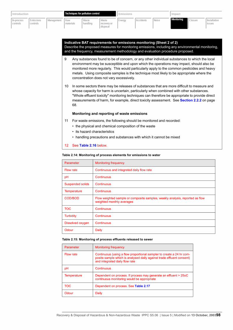
In-process controls
Emissions controls
Management Raw materials
Waste handling
Waste recovery or disposal
Energy Accidents Noise Monitoring Closure Installation issues
Introduction Techniques Emissions Impact
Monitoring
Techniques for pollution control
9 Any substances found to be of concern, or any other individual substances to which the local environment may be susceptible and upon which the operations may impact, should also be monitored more regularly. This would particularly apply to the common pesticides and heavy metals. Using composite samples is the technique most likely to be appropriate where the concentration does not vary excessively.
10 In some sectors there may be releases of substances that are more difficult to measure and whose capacity for harm is uncertain, particularly when combined with other substances. "Whole effluent toxicity" monitoring techniques can therefore be appropriate to provide direct measurements of harm, for example, direct toxicity assessment. See Section 2.2.2 on page 68.
Monitoring and reporting of waste emissions
11 For waste emissions, the following should be monitored and recorded:• the physical and chemical composition of the waste• its hazard characteristics• handling precautions and substances with which it cannot be mixed
12 See Table 2.16 below.
Table 2.14: Monitoring of process elements for emissions to water
Parameter Monitoring frequency
Flow rate Continuous and integrated daily flow rate
pH Continuous
Suspended solids Continuous
Temperature Continuous
COD/BOD Flow weighted sample or composite samples, weekly analysis, reported as flow weighted monthly averages
TOC Continuous
Turbidity Continuous
Dissolved oxygen Continuous
Odour Daily
Table 2.15: Monitoring of process effluents released to sewer
Parameter Monitoring frequency
Flow rate Continuous (using a flow proportional sampler to create a 24 hr com-posite sample which is analysed daily against trade effluent consent) and integrated daily flow rate
pH Continuous
Temperature Dependent on process. If process may generate an effluent > 25oC continuous monitoring would be appropriate
TOC Dependent on process. See Table 2.17
Odour Daily
Indicative BAT requirements for emissions monitoring (Sheet 2 of 2)Describe the proposed measures for monitoring emissions, including any environmental monitoring, and the frequency, measurement methodology and evaluation procedure proposed.
Recovery & Disposal of Hazardous & Non-hazardous Waste IPPC S5.06 | Issue 5 | Modified on 13 October, 200398
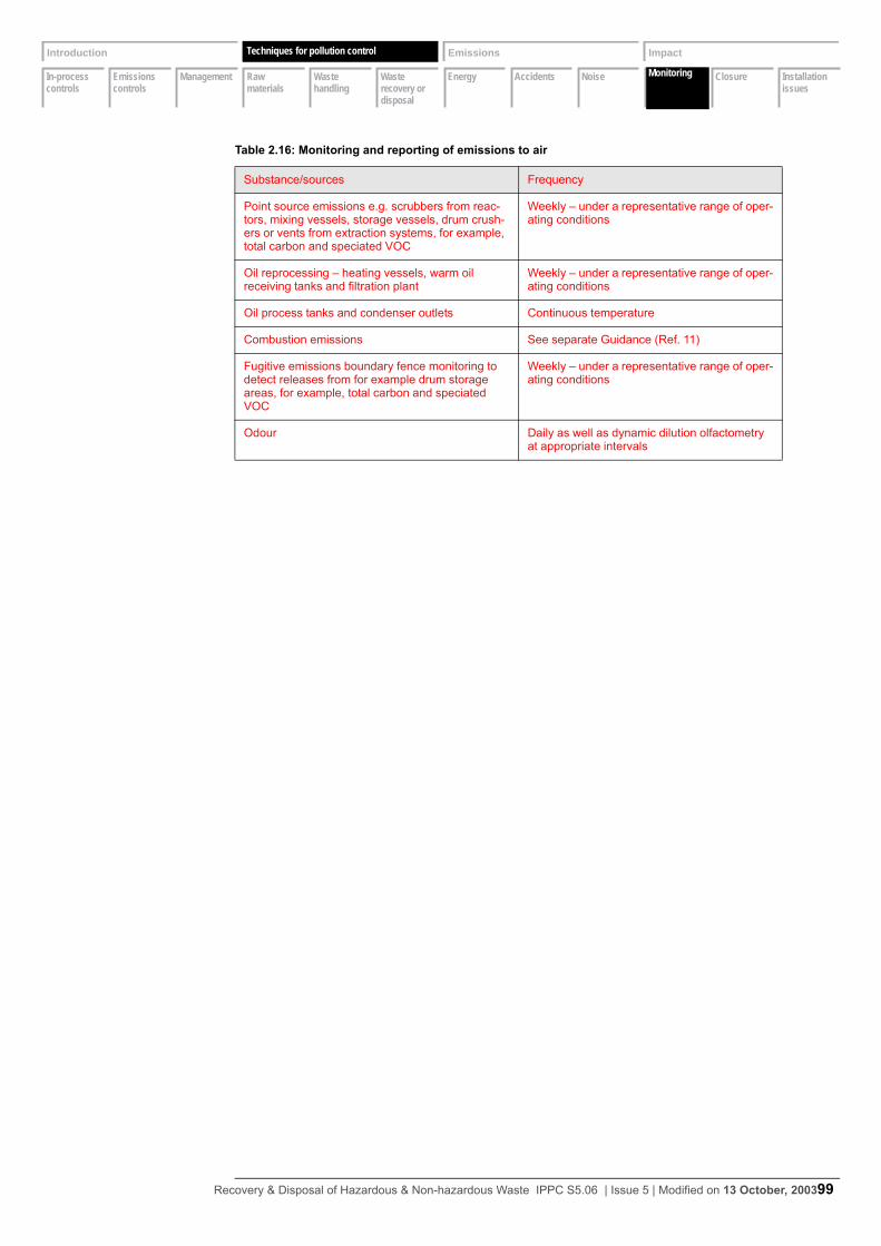
In-process controls
Emissions controls
Management Raw materials
Waste handling
Waste recovery or disposal
Energy Accidents Noise Monitoring Closure Installation issues
Introduction Techniques Emissions Impact
Monitoring
Techniques for pollution control
Table 2.16: Monitoring and reporting of emissions to air
Substance/sources Frequency
Point source emissions e.g. scrubbers from reac-tors, mixing vessels, storage vessels, drum crush-ers or vents from extraction systems, for example, total carbon and speciated VOC
Weekly – under a representative range of oper-ating conditions
Oil reprocessing – heating vessels, warm oil receiving tanks and filtration plant
Weekly – under a representative range of oper-ating conditions
Oil process tanks and condenser outlets Continuous temperature
Combustion emissions See separate Guidance (Ref. 11)
Fugitive emissions boundary fence monitoring to detect releases from for example drum storage areas, for example, total carbon and speciated VOC
Weekly – under a representative range of oper-ating conditions
Odour Daily as well as dynamic dilution olfactometry at appropriate intervals
Recovery & Disposal of Hazardous & Non-hazardous Waste IPPC S5.06 | Issue 5 | Modified on 13 October, 200399

In-process controls
Emissions controls
Management Raw materials
Waste handling
Waste recovery or disposal
Energy Accidents Noise Monitoring Closure Installation issues
Introduction Techniques Emissions Impact
Monitoring
Techniques for pollution control
2.10.2 Environmental monitoring (beyond installation)
Indicative BAT requirements for environmental monitoring (beyond installation)(Sheet 1 of 2)Describe the proposed measures for monitoring emissions, including any environmental monitoring, and the frequency, measurement methodology and evaluation procedure proposed.
1 The Operator should consider the need for environmental monitoring to assess the effects of emissions to controlled water, groundwater, air or land, or emissions of noise or odour.
2 Environmental monitoring may be required, for example, when:• there are vulnerable receptors• the emissions are a significant contributor to an Environmental Quality Standard (EQS) that
may be at risk• the Operator is looking for departures from standards based on lack of effect on the environ-
ment;• to validate modelling work.
3 The need should be considered for:• groundwater, where it should be designed to characterise both quality and flow and take into
account short- and long-term variations in both. Monitoring will need to take place both up-gradient and down-gradient of the site
• surface water, where consideration will be needed for sampling, analysis and reporting for upstream and downstream quality of the controlled water
• air, including odour• land contamination, including vegetation, and agricultural products• assessment of health impacts• noise
4 Where environmental monitoring is needed, the following should be considered in drawing up proposals:• determinands to be monitored, standard reference methods, sampling protocols• monitoring strategy, selection of monitoring points, optimisation of monitoring approach• determination of background levels contributed by other sources• uncertainty for the employed methodologies and the resultant overall uncertainty of meas-
urement• quality assurance (QA) and quality control (QC) protocols, equipment calibration and mainte-
nance, sample storage and chain of custody/audit trail• reporting procedures, data storage, interpretation and review of results, reporting format for
the provision of information for the Regulation
5 Guidance on air quality monitoring strategies and methodologies can be found in Monitoring Guidance.
Recovery & Disposal of Hazardous & Non-hazardous Waste IPPC S5.06 | Issue 5 | Modified on 13 October, 2003

In-process controls
Emissions controls
Management Raw materials
Waste handling
Waste recovery or disposal
Energy Accidents Noise Monitoring Closure Installation issues
Introduction Techniques Emissions Impact
Monitoring
Techniques for pollution control
2.10.3 Monitoring of process variables
Monitoring of emissions to air:• Oil reprocessing installations should have in place daily olfactory odour monitoring pro-
grammes (see Section 2.2.6 on page 79).• Only larger (> 50 MW) boiler plant may have sufficient impact on local air quality to require
specific air quality management programmes.• Otherwise daily visual monitoring to air for smoke, dust, litter, plumes and daily olfactory
odour monitoring, with more extensive monitoring if nuisance is occurring or appears likely (see Ref. 21).
Monitoring of emissions to land:
6 It is unlikely that sludge would be re-used for agricultural benefit or ecological improvement or where sensitive soil systems or terrestrial ecosystems are at risk from indirect emission via the air. Otherwise there should no emissions to land and consequently there are no monitoring requirements.
Monitoring of emissions to groundwater:
7 Groundwater monitoring should take place where:• there are any subsurface structures carrying or holding waste or other harmful substances
for example, fuel• there is uncertainty about surfaces on operational areas and drainage systems, especially
on older sites
Indicative BAT requirements for monitoring of process variables Describe the proposed measures for monitoring emissions, including any environmental monitoring, and the frequency, measurement methodology and evaluation procedure proposed.
1 Some process variables may affect the environment and these should be identified and moni-tored as appropriate. Examples might be:
2 as shown in Table 2.17.
Table 2.17: Monitoring of resource use
Resource variable Comment Monitoring frequency
Fresh water use across the instal-lation and at individual points of use
See Section 2.4.3 on page 89 Normally continuous and recorded
Energy consumption across the installation and at individual points of use
Normally continuous and recorded
Indicative BAT requirements for environmental monitoring (beyond installation)(Sheet 2 of 2)Describe the proposed measures for monitoring emissions, including any environmental monitoring, and the frequency, measurement methodology and evaluation procedure proposed.
Recovery & Disposal of Hazardous & Non-hazardous Waste IPPC S5.06 | Issue 5 | Modified on 13 October, 2003
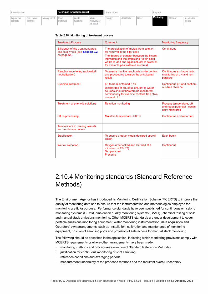
In-process controls
Emissions controls
Management Raw materials
Waste handling
Waste recovery or disposal
Energy Accidents Noise Monitoring Closure Installation issues
Introduction Techniques Emissions Impact
Monitoring
Techniques for pollution control
2.10.4 Monitoring standards (Standard Reference Methods)
The Environment Agency has introduced its Monitoring Certification Scheme (MCERTS) to improve the quality of monitoring data and to ensure that the instrumentation and methodologies employed for monitoring are fit for purpose. Performance standards have been published for continuous emissions monitoring systems (CEMs), ambient air quality monitoring systems (CAMs) , chemical testing of soils and manual stack emissions monitoring. Other MCERTS standards are under development to cover portable emissions monitoring equipment, water monitoring instrumentation, data acquisition and Operators' own arrangements, such as installation, calibration and maintenance of monitoring equipment, position of sampling ports and provision of safe access for manual stack monitoring.
The following should be described in the application, indicating which monitoring provisions comply with MCERTS requirements or where other arrangements have been made:• monitoring methods and procedures (selection of Standard Reference Methods)• justification for continuous monitoring or spot sampling• reference conditions and averaging periods• measurement uncertainty of the proposed methods and the resultant overall uncertainty
Table 2.18: Monitoring of treatment process
Treatment Process Comment Monitoring frequency
Efficiency of the treatment proc-ess as a whole (see Section 2.2 on page 64)
The precipitation of metals from solution for removal in the filter cakeThe degree of transfer between the incom-ing waste and the emissions (to air, solid waste to land and liquid effluent to sewer of for example pesticides or solvents)
Continuous
Reaction monitoring (acid-alkali neutralisation)
To ensure that the reaction is under control and proceeding towards the anticipated result
Continuous and automatic monitoring of pH and tem-perature
Cyanide treatment pH to be maintained > 10Discharges of aqueous effluent to water-courses should therefore be monitored continuously for cyanide content, free chlo-rine and pH
Continuous pH and continu-ous free chlorine
Treatment of phenolic solutions Reaction monitoring Process temperature, pH and redox potential - contin-ually monitored
Oil re-processing Maintain temperature <90 °C Continuous and recorded
Temperature in heating vessels and condenser outlets
Stabilisation To ensure product meets declared specifi-cation
Each batch
Wet air oxidation Oxygen (interlocked and alarmed at a minimum of 2% 02)TemperaturePressure
Continuous
Recovery & Disposal of Hazardous & Non-hazardous Waste IPPC S5.06 | Issue 5 | Modified on 13 October, 2003
In-process controls
Emissions controls
Management Raw materials
Waste handling
Waste recovery or disposal
Energy Accidents Noise Monitoring Closure Installation issues
Introduction Techniques Emissions Impact
Monitoring
Techniques for pollution control
• criteria for the assessment of non-compliance with Permit limits and details of monitoring strategy aimed at demonstration of compliance
• reporting procedures and data storage of monitoring results, record keeping and reporting intervals for the provision of information to the Regulator
• procedures for monitoring during start-up and shut-down and abnormal process conditions• drift correction calibration intervals and methods• the accreditation held by samplers and laboratories or details of the people used and the training/
competencies
Indicative BAT requirements for monitoring standards (Standard Reference Methods) Describe the proposed measures for monitoring emissions, including any environmental monitoring, and the frequency, measurement methodology and evaluation procedure proposed.
1 As far as possible, Operators should ensure their monitoring arrangements comply with the requirements of MCERTS where available, for example using certified instruments and equip-ment, and using a stack testing organisation accredited to MCERTS standards. Where the monitoring arrangements are not in accordance with MCERTS requirements, the Operator should provide justification and describe the monitoring provisions in detail. See MCERTS approved equipment link via www.environment-agency.gov.uk/business/mcerts for future information on MCERTS and a listing of MCERTS equipment.
Sampling and analysis standards
2 The analytical methods given in Appendix 1 should be used. In the event of other substances needing to be monitored, standards should be used in the following order of priority:• Comité Européen de Normalisation (CEN)• British Standards Institution (BSI)• International Standardisation Organisation (ISO)• United States Environmental Protection Agency (US EPA)• American Society for Testing and Materials (ASTM)• Deutches Institut für Normung (DIN)• Verein Deustcher Ingenieure (VDI)• Association Française de Normalisation (AFNOR)
3 Further guidance on standards for monitoring gaseous releases relevant to IPC/IPPC is given in the Monitoring Guidance. A series of updated Guidance Notes covering this subject is being prepared. This guidance specifies manual methods of sampling and analysis that will also be suitable for calibration of continuous emission monitoring instruments. Further guidance relevant to water and waste is available from the publications of the Standing Committee of Analysts.
4 If in doubt the Operator should consult the Regulator.
Recovery & Disposal of Hazardous & Non-hazardous Waste IPPC S5.06 | Issue 5 | Modified on 13 October, 2003
In-process controls
Emissions controls
Management Raw materials
Waste handling
Waste recovery or disposal
Energy Accidents Noise Monitoring Closure Installation issues
Introduction Techniques Emissions Impact
Closure
Techniques for pollution control
2.11 Closure
The PPC Regulations require an Applicant to submit a site report, describing the condition of the site, as part of the application. Guidance on this is in Annex C of the Guide for Applicants (see IPPC Part A(1) Installations: Guide for (Applicants England and Wales) (includes Preparation of a Site Report in a Permit Application) (EA website).
Operators of new Installations are required to return the site to a ‘satisfactory state’ which had been previously been identified in the site report. Installations that transfer from the Waste Management Licensing regime that are SWMA’s are subject to additional closure requirements as the operator is required to return the site to a ‘satisfactory state’ which would reflect the state of the site when the WML was originally issued.
Indicative BAT requirements for closure (Sheet 1 of 2)Describe the proposed measures, upon definitive cessation of activities, to avoid any pollution risk and return the site of operation to a satisfactory state (including, where appropriate, measures relat-ing to the design and construction of the installation).
1 Operations during the IPPC PermitOperations during the life of the IPPC Permit should not lead to any deterioration of the site if the requirements of the other sections of this and the specific-sector notes are adhered to. Should any instances arise which have, or might have, impacted on the state of the site, the Operator should record them along with any further investigation or ameliorating work carried out. This will ensure that there is a coherent record of the state of the site throughout the period of the IPPC Permit. This is as important for the protection of the Operator as it is for the protection of the environment. Any changes to this record should be submitted to the Regulator.
2 Steps to be taken at the design-and-build stage of the activitiesCare should be taken at the design stage to minimise risks during decommissioning. For existing installations, where potential problems are identified, a programme of improvements should be put in place to a timescale agreed with the Regulator. Designs should ensure that:• underground tanks and pipework are avoided where possible (unless protected by second-
ary containment or a suitable monitoring programme)• there is provision for the draining and clean-out of vessels and pipework prior to dismantling• lagoons and landfills are designed with a view to their eventual clean-up or surrender• insulation is provided that is readily dismantled without dust or hazard• materials used are recyclable (having regard for operational or other environmental objec-
tives)
3 The site-closure planA site closure plan should be maintained to demonstrate that, in its current state, the installa-tion can be decommissioned to avoid any pollution risk and return the site of operation to a satisfactory state. The plan should be kept updated as material changes occur. Common sense should be used in the level of detail, since the circumstances at closure will affect the final plans. However, even at an early stage, the closure plan should include:• either the removal or the flushing out of pipelines and vessels where appropriate and their
complete emptying of any potentially harmful contents• plans of all underground pipes and vessels• the method and resource necessary for the clearing of lagoons
Recovery & Disposal of Hazardous & Non-hazardous Waste IPPC S5.06 | Issue 5 | Modified on 13 October, 2003

In-process controls
Emissions controls
Management Raw materials
Waste handling
Waste recovery or disposal
Energy Accidents Noise Monitoring Closure Installation issues
Introduction Techniques Emissions Impact
Closure
Techniques for pollution control
• the method of ensuring that any on-site landfills can meet the equivalent of surrender condi-tions
• the removal of asbestos or other potentially harmful materials unless agreed that it is reason-able to leave such liabilities to future owners
• methods of dismantling buildings and other structures, see Ref 1 which gives guidance on the protection of surface and groundwater at construction and demolition-sites
• testing of the soil to ascertain the degree of any pollution caused by the activities and the need for any remediation to return the site to a satisfactory state as defined by the initial site report
4 For existing activities, the Operator should complete any detailed studies, and submit the site-closure plan as an improvement condition to a timescale to be agreed with the Regulator but in any case within the timescale given in Section 1.1 on page 2 (Note that radioactive sources are not covered by this legislation, but decommissioning plans should be co-ordinated with responsibilities under the Radioactive Substances Act 1993.)
Indicative BAT requirements for closure (Sheet 2 of 2)Describe the proposed measures, upon definitive cessation of activities, to avoid any pollution risk and return the site of operation to a satisfactory state (including, where appropriate, measures relat-ing to the design and construction of the installation).
Recovery & Disposal of Hazardous & Non-hazardous Waste IPPC S5.06 | Issue 5 | Modified on 13 October, 2003
In-process controls
Emissions controls
Management Raw materials
Waste handling
Waste recovery or disposal
Energy Accidents Noise Monitoring Closure Installation issues
Introduction Techniques Emissions Impact
Installation issues
Techniques for pollution control
2.12 Installation issues
It is possible that some waste management activities that are undertaken at an installation may not be ‘listed activities’ themselves and where they are not ‘directly associated activities’ they cannot be incorporated into the PPC permit. These activities will be required to be regulated under the Waste Management Licensing Regulations 1994 either under a WML or an appropriate exemption
Wastes that are stored to treated within the installation boundary that are not subject to the PPC permit, must be clearly marked and stored in clearly designated areas
In some cases it is possible that actions that benefit the environmental performance of the overall installation will increase the emissions from one Permit-holder’s activities. For example, taking treated effluent as a raw water supply will probably slightly increase emissions from that activity, but could dramatically cut the total emissions from the whole installation.
Where you are not the only Operator of the installation, describe the proposed techniques and measures (including those to be taken jointly by yourself and other Operators) for ensuring the satisfactory operation of the whole installation
Indicative BAT requirements for installation issues Where you are not the only Operator of the installation, describe the proposed techniques and measures (including those to be taken jointly by yourself and other Operators) for ensuring the sat-isfactory operation of the whole installation.
1 The Operator should consider possibilities for minimising environmental impact to the environ-ment as a whole, by operating together with other Permit holders. Possibilities include:• Communication procedures between the various Permit-holders; in particular those needed
to ensure that the risk of environmental incidents is minimised.• Benefiting from the economies of scale to justify the installation of a CHP plant.• The combining of combustible wastes to justify a combined waste-to-energy/CHP plant.• The waste from one activity being a possible feedstock for another.• The treated effluent from one activity being of adequate quality to be the raw water feed for
another activity.• The combining of effluent to justify a combined or upgraded effluent-treatment plant.• The avoidance of accidents from one activity that may have a detrimental knock-on effect on
the neighbouring activity.• Land contamination from one activity affecting another – or the possibility that one Operator
owns the land on which the other is situated.
Recovery & Disposal of Hazardous & Non-hazardous Waste IPPC S5.06 | Issue 5 | Modified on 13 October, 2003
Emissions inventory
Emissions benchmarks
Biological oxygen demand (BOD)
Chemical oxygen demand (COD)
Halogens Heavy metals Nitrogen oxides
Nutrients Suspended solids
Sulphur dioxide
Volatile organic compounds
Introduction Techniques Emissions Impact
Emissions inventory
Emission benchmarks
3 Emission benchmarks
3.1 Emissions inventory
The Regulations require the Applicant to describe the nature, quantities and sources of foreseeable emissions into each medium. This will be done by completing the inventory of emission and consumption in the H1 software tool. The information required is as follows.
Provide a table of significant emissions of substances (except noise, vibration, odour and heat which are covered in their respective sections) that will result from the proposals and should include, preferably in order of significance:• substance (where the substance is a mixture, for example, VOCs or COD, separate identification of
the main constituents or inclusion of an improvement proposal to identify them)• source, including height, location and efflux velocity• media to which it is released• any relevant EQS or other obligations• benchmark• proposed emissions normal/max expressed, as appropriate for:
– mass/unit time– concentration– annual mass emissions
• statistical basis (average, percentile etc.)• notes covering the Operators confidence in his ability to meet the benchmark values• if intermittent, the appropriate frequencies• plant loads at which the data is applicable• whether measured or calculated (the method of calculation should be provided)
The response should clearly state whether the emissions are current emission rates or those planned following improvements, and should cover emissions under both normal and abnormal conditions for:• point-source emissions to surface water, groundwater and sewer• waste emissions• point-source emissions to air• significant fugitive emissions to all media, identifying the proportion of each substance released that
is due to fugitives rather than point-source releases• abnormal emissions from emergency relief vents, flares and the like• indirect and direct emission of carbon dioxide associated with energy consumed or generated
Emissions of carbon dioxide associated with energy use should be broken down by energy type and, in the case of electricity, by source, for example, public supply, direct supply or on-site generation. Where energy is generated on-site, or from a direct (non-public) supplier, the Operator should specify and use the appropriate factor. Standard factors for carbon dioxide emissions are provided in the guidance note H2 Energy efficiency for IPPC.
Where VOCs are released, the main chemical constituents of the emissions should be identified.
Recovery & Disposal of Hazardous & Non-hazardous Waste IPPC S5.06 | Issue 5 | Modified on 13 October, 2003

Emissions inventory
Emissions benchmarks
Biological oxygen demand (BOD)
Chemical oxygen demand (COD)
Halogens Heavy metals Nitrogen oxides
Nutrients Suspended solids
Sulphur dioxide
Volatile organic compounds
Introduction Techniques Emissions Impact
Emissions inventory
Emission benchmarks
For waste, emissions relate to any wastes removed from the installation, or disposed of at the installation under the conditions of the Permit, for example, landfill. Each waste should have its composition determined and the amounts expressed in terms of cubic metres or tonnes per month. A suitable table on which to record this information is provided in the electronic version of this Guidance Note.
Indicative BAT requirements for the emissions inventory Describe the nature, quantities and sources of foreseeable emissions into each medium (which will result from the techniques proposed in Section 2).
1 The Operator should compare the emissions with the benchmark values given in the remainder of this Section.
2 Where the benchmarks are not met, the Operator should revisit the responses made in Section 2 as appropriate and make proposals for improvements or justify not doing so as part of the BAT assessment.
Recovery & Disposal of Hazardous & Non-hazardous Waste IPPC S5.06 | Issue 5 | Modified on 13 October, 2003

Emissions inventory
Emissions benchmarks
Biological oxygen demand (BOD)
Chemical oxygen demand (COD)
Halogens Heavy metals Nitrogen oxides
Nutrients Suspended solids
Sulphur dioxide
Volatile organic compounds
Introduction Techniques Emissions Impact
Emission benchmarks
Emission benchmarks
3.2 Emission benchmarks
Introduction to emission benchmarks
Guidance is given below on release concentrations or mass release rates achievable for key substances using the best combination of techniques. These BAT-based benchmarks are not mandatory release limits and reference should be made to Section 1 and the Guide for Applicants regarding their use.
3.2.1 Emissions to air associated with the use of BAT
The emissions quoted below are daily averages based upon continuous monitoring during the period of operation. See Section 3.2.6 on page 119 for the standard conditions that should be applied. Care should always be taken to convert benchmark and proposed releases to the same reference conditions for comparison. To convert measured values to reference conditions, see the Monitoring Guidance for more information. The benchmarks given do not take sampling, analytical errors, or uncertainties into account. These will be considered when setting an ELV for a Permit.
Limits in Permits may be set for mean or median values over long or short periods. The periods and limits selected should reflect:• the manner in which the emission may impact upon the environment• likely variations which will arise during operation within BAT• possible failure modes and their consequences• the capabilities of the monitoring and testing system employed
Where emissions are expressed in terms of concentrations and where continuous monitors are employed, it is recommended that limits are defined such that:• not more than one calendar monthly average during any rolling twelve month period shall exceed
the benchmark value by more than 10%• not more than one half hour period during any rolling 24 hour period shall exceed the benchmark
value by more than 50% (for the purpose of this limit half hourly periods commence on the hour and the half hour)
Where spot tests are employed: • the half hour limit above shall be applied over the period of the test • the mean of three consecutive tests taken during a calendar year shall not exceed the benchmark
value by more than 10%
Recovery & Disposal of Hazardous & Non-hazardous Waste IPPC S5.06 | Issue 5 | Modified on 13 October, 2003
Emissions inventory
Emissions benchmarks
Biological oxygen demand (BOD)
Chemical oxygen demand (COD)
Halogens Heavy metals Nitrogen oxides
Nutrients Suspended solids
Sulphur dioxide
Volatile organic compounds
Introduction Techniques Emissions Impact
Emission benchmarks
Emission benchmarks
3.2.2 Emissions to water associated with the use of BAT
Wastewater treatment systems can maximise the removal of metals using precipitation, sedimentation and possibly filtration. The reagents used for precipitation may be hydroxide, sulphide or a combination of both, depending on the mix of metals present. It is also practicable in many cases to re-use treated water.
Where automatic sampling systems are employed, limits may be defined such that:• not more than 5% of samples shall exceed the benchmark value
Where spot samples are taken:• no spot sample shall exceed the benchmark value by more than 50%
3.2.3 Standards and obligations
In addition to meeting the requirements of BAT, there are other national and international standards and obligations that must either be safeguarded through the IPPC Permit or, at least, taken into account in setting Permit conditions. This is particularly the case for any EC-based EQSs.
EC-based EQ standards
IPPC: A Practical Guide explains how these should be taken into account and contains an annex listing the relevant standards. (See Appendix 2 for equivalent legislation in Scotland and Northern Ireland). They can be summarised as follows:
Air quality• Statutory Instrument 1989 No 317, Clean Air, The Air Quality Standards Regulations 1989 gives limit
values in air for nitrogen dioxide (any emission from the process should not result in a breach of this standard beyond the site boundary), sulphur dioxide and suspended particulates.
• Environmental Protection, The Air Quality Regulations 1997.• Statutory Instrument 2000 No.928, Air Quality (England) Regulations 2000 gives air quality objec-
tives to be achieved by:– 2005 for nitrogen dioxide– 2004 for SO2 and PM10– 2003 for CO, 1,3-butadiene and benzene– in two stages for lead by 2004 and 2008 respectively
Water quality• Directive 76/464/EEC on Pollution Caused by Dangerous Substances Discharged to Water con-
tains two lists of substances. List I relates to the most dangerous, and standards are set out in vari-ous daughter Directives. List II substances must also be controlled. Annual mean concentration limits for receiving waters for List I substances can be found in SI 1989/2286 and SI 1992/337 the Surface Water (Dangerous Substances Classification) Regulations. Values for List II substances are contained in SI 1997/2560 and SI 1998/389. Daughter Directives cover EQS values for mer-cury, cadmium, hexachlorocyclohexane, DDT, carbon tetrachloride, pentachlorophenol, aldrin, diel-drin, endrin, isodrin, hexachlorobenzene, hexachlorobutadiene, chloroform,1,2-dichloroethane, trichloroethane, perchloroethane and trichlorobenzene.
Recovery & Disposal of Hazardous & Non-hazardous Waste IPPC S5.06 | Issue 5 | Modified on 13 October, 2003

Emissions inventory
Emissions benchmarks
Biological oxygen demand (BOD)
Chemical oxygen demand (COD)
Halogens Heavy metals Nitrogen oxides
Nutrients Suspended solids
Sulphur dioxide
Volatile organic compounds
Introduction Techniques Emissions Impact
Emission benchmarks
Emission benchmarks
• Other waters with specific uses have water quality concentration limits for certain substances. These are covered by the following Regulations:– SI 1991/1597 Bathing Waters (Classification) Regulations– SI 1992/1331 and Direction 1997 Surface Waters (Fishlife) (Classification) Regulations– SI 1997/1332 Surface Waters (Shellfish) (Classification) Regulations– SI 1996/3001 The Surface Waters (Abstraction and Drinking Water) (Classification) Regulations
Future likely changes include:• Some air quality and water quality standards may be replaced by new ones in the near future.• The SED on the limitation of emissions of VOCs due to the use of organic solvents in certain activi-
ties and installations.
Other standards and obligations
Those most frequently applicable to most sectors are:• Hazardous Waste Incineration Directive• Waste Incineration Directive.• Large Combustion Plant Directive.• Reducing Emissions of VOCs and Levels of Ground Level Ozone: a UK Strategy (published by the
Department of the Environment in October 1993. It sets out how the Government expects to meet its obligations under the UNECE VOCs Protocol to reduce its emissions by 30% (based on 1988 levels) by 1999, including the reductions projected for the major industrial sectors).
• Water Quality Objectives – assigned water quality objectives to inland rivers and water courses (ref. Surface (Rivers Ecosystem) Classification).
• The UNECE convention on long-range transboundary air pollution (negotiations are now underway which could lead to a requirement further to reduce emissions of NOx and VOCs. A requirement to further reduce SO2 emissions from all sources has been agreed. The second Sulphur protocol (Oslo, 1994) obliges the UK to reduce SO2 emissions by 80% (based on 1980 levels) by 2010).
• The Montreal Protocol.• The Habitats Directive (see Section 4.3 on page 132).• Sulphur Content of Certain Liquid Fuels Directive 1999/32/EC (from 1 January 2003, the sulphur
content of heavy fuel oil must not exceed 1% except when it is burnt in plants fitted with SO2 abate-ment equipment. Sulphur levels in gas oil must not exceed 0.2% from 1 July 2000, and 0.1% from the start of 2008.)
3.2.4 Units for benchmarks and setting limits in Permits
Releases can be expressed in terms of:• “concentration” (for example mg/l or mg/m3), which is a useful day-to-day measure of the effec-
tiveness of any abatement plant and is usually measurable and enforceable The total flow must be measured/controlled as well
• “specific mass release” (for example, kg/ product or input or other appropriate parameter), which is a measure of the overall environmental performance of the plant (including the abatement plant) compared with similar plants elsewhere
• “absolute mass release” (for example, kg/hr, t/yr), which relates directly to environmental impact
Recovery & Disposal of Hazardous & Non-hazardous Waste IPPC S5.06 | Issue 5 | Modified on 13 October, 2003
Emissions inventory
Emissions benchmarks
Biological oxygen demand (BOD)
Chemical oxygen demand (COD)
Halogens Heavy metals Nitrogen oxides
Nutrients Suspended solids
Sulphur dioxide
Volatile organic compounds
Introduction Techniques Emissions Impact
Emission benchmarks
Emission benchmarks
When endeavouring to reduce the environmental impact of an installation, its performance against each of these levels should be considered, as appropriate to the circumstances, in assessing where improvements can best be made.
When setting limits in Permits, the most appropriate measure will depend on the purpose of the limit. It may also be appropriate to use surrogate parameters, which reflect optimum environmental performance of plant as the routine measurement, supported by less frequent check-analyses on the final concentration. Examples of surrogate measures would be the continuous measurement of conductivity (after ion-exchange treatment) or total carbon (before a guard-column in activated carbon treatment) to indicate when regeneration or replacement is required.
The emission level figures given in this chapter are based on average figures, not on maximum, short-term peak values, which could be expected to be higher. The emission levels given are based on a typical averaging period of not less than 30 minutes and not greater than 24 hours.
3.2.5 Statistical basis for benchmarks and limits in Permits
Conditions in Permits can be set with percentile, mean or median values over annual, monthly or daily periods, which reflect probable variation in performance. In addition, absolute maxima can be set.
Where there are known failure modes, which will occur even when applying BAT, limits in Permits may be specifically disapplied, but with commensurate requirements to notify the Regulator and to take specific remedial action.
For water: UK benchmarks or limits are most frequently 95 percentile concentrations or absolute concentrations, (with flow limited on a daily average or maximum basis).
For air: benchmarks or limits are most frequently expressed as daily averages or, typically 95 percent of hourly averages.
3.2.6 Reference conditions for releases to air
The reference conditions of substances in releases to air from point-sources are: • Temperature 273 K (0oC), pressure 101.3 kPa (1 atmosphere), no correction for water vapour or
oxygen.• The reference conditions for combustion or incineration processes are as given in the appropriate
Guidance Note.
These reference conditions relate to the benchmark release levels given in this Note and care should always be taken to convert benchmark and proposed releases to the same reference conditions for comparison. The Permit may employ different reference conditions if they are more suitable for the process in question.
To convert measured values to reference conditions, see the Monitoring Guidance for more information.
Recovery & Disposal of Hazardous & Non-hazardous Waste IPPC S5.06 | Issue 5 | Modified on 13 October, 2003
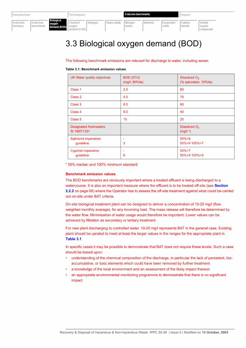
Emissions inventory
Emissions benchmarks
Biological oxygen demand (BOD)
Chemical oxygen demand (COD)
Halogens Heavy metals Nitrogen oxides
Nutrients Suspended solids
Sulphur dioxide
Volatile organic compounds
Introduction Techniques Emissions Impact
Biological oxygen demand (BOD)
Emission benchmarks
3.3 Biological oxygen demand (BOD)
The following benchmark emissions are relevant for discharge to water, including sewer.
* 50% median and 100% minimum standard
Benchmark emission valuesThe BOD benchmarks are obviously important where a treated effluent is being discharged to a watercourse. It is also an important measure where the effluent is to be treated off-site (see Section 2.2.2 on page 68) where the Operator has to assess the off-site treatment against what could be carried out on-site under BAT criteria.
On-site biological treatment plant can be designed to deliver a concentration of 10-20 mg/l (flow weighted monthly average), for any incoming load. The mass release will therefore be determined by the water flow. Minimisation of water usage would therefore be important. Lower values can be achieved by filtration as secondary or tertiary treatment.
For new plant discharging to controlled water, 10-20 mg/l represents BAT in the general case. Existing plant should be uprated to meet at least the larger values in the ranges for the appropriate plant in Table 3.1.
In specific cases it may be possible to demonstrate that BAT does not require these levels. Such a case should be based upon:• understanding of the chemical composition of the discharge, in particular the lack of persistent, bio-
accumulative, or toxic elements which could have been removed by further treatment• a knowledge of the local environment and an assessment of the likely impact thereon• an appropriate environmental monitoring programme to demonstrate that there is no significant
impact
Table 3.1: Benchmark emission values
UK Water quality objectives BOD (ATU) (mg/l, 90%ile)
Dissolved O2(% saturation, 10%ile)
Class 1 2.5 80
Class 2 4.0 70
Class 3 6.0 60
Class 4 8.0 40
Class 5 15 20
Designated freshwaters SI 1997/1331
Dissolved O2(mg/l *)
Salmonid imperative: guideline:
-3
50%>950%>9 100%>7
Cyprinid imperative: guideline:
-6
50%>750%>9 100%>5
Recovery & Disposal of Hazardous & Non-hazardous Waste IPPC S5.06 | Issue 5 | Modified on 13 October, 2003

Emissions inventory
Emissions benchmarks
Biological oxygen demand (BOD)
Chemical oxygen demand (COD)
Halogens Heavy metals Nitrogen oxides
Nutrients Suspended solids
Sulphur dioxide
Volatile organic compounds
Introduction Techniques Emissions Impact
Chemical oxygen demand (COD)
Emission benchmarks
3.4 Chemical oxygen demand (COD)
Other applicable standards and obligationsNone
Benchmark emission valuesNot available
Emission limit values would normally only be set if the impact of the COD was understood and there is a clear reason for setting the limit, such as to drive a reduction to an agreed plan, as a toxicity surrogate or where there are agreed actions that can be employed to control it. Thus it is more important that there is:• an understanding of the chemical composition of the discharge, in particular the lack of persistent,
bioaccumulative, or toxic elements which could have been removed by further treatment• a knowledge of the local environment and an assessment of the likely impact thereon• an appropriate environmental monitoring programme to demonstrate that there is no significant
impact
Recovery & Disposal of Hazardous & Non-hazardous Waste IPPC S5.06 | Issue 5 | Modified on 13 October, 2003
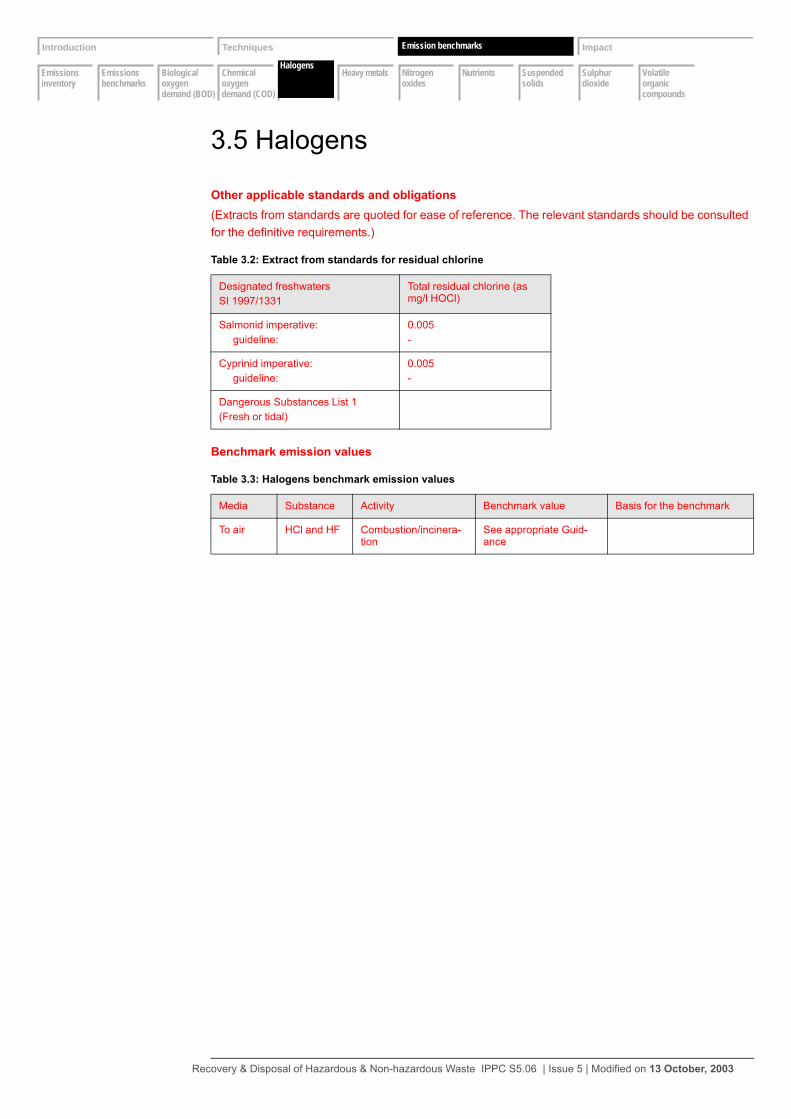
Emissions inventory
Emissions benchmarks
Biological oxygen demand (BOD)
Chemical oxygen demand (COD)
Halogens Heavy metals Nitrogen oxides
Nutrients Suspended solids
Sulphur dioxide
Volatile organic compounds
Introduction Techniques Emissions Impact
Halogens
Emission benchmarks
3.5 Halogens
Other applicable standards and obligations(Extracts from standards are quoted for ease of reference. The relevant standards should be consulted for the definitive requirements.)
Benchmark emission values
Table 3.2: Extract from standards for residual chlorine
Designated freshwaters SI 1997/1331
Total residual chlorine (as mg/l HOCl)
Salmonid imperative: guideline:
0.005-
Cyprinid imperative: guideline:
0.005-
Dangerous Substances List 1(Fresh or tidal)
Table 3.3: Halogens benchmark emission values
Media Substance Activity Benchmark value Basis for the benchmark
To air HCl and HF Combustion/incinera-tion
See appropriate Guid-ance
Recovery & Disposal of Hazardous & Non-hazardous Waste IPPC S5.06 | Issue 5 | Modified on 13 October, 2003
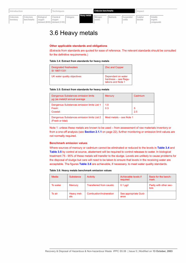
Emissions inventory
Emissions benchmarks
Biological oxygen demand (BOD)
Chemical oxygen demand (COD)
Halogens Heavy metals Nitrogen oxides
Nutrients Suspended solids
Sulphur dioxide
Volatile organic compounds
Introduction Techniques Emissions Impact
Heavy metals
Emission benchmarks
3.6 Heavy metals
Other applicable standards and obligations(Extracts from standards are quoted for ease of reference. The relevant standards should be consulted for the definitive requirements.)
Note 1: unless these metals are known to be used – from assessment of raw materials inventory or from a one-off analysis (see Section 2.1.1 on page 22), further monitoring or emission limit values are not normally required.
Benchmark emission valuesWhere sources of mercury or cadmium cannot be eliminated or reduced to the levels in Table 3.4 and Table 3.5 by control at source, abatement will be required to control releases to water. In biological treatment 75 - 95% of these metals will transfer to the sludge. Levels are unlikely to cause problems for the disposal of sludge but care will need to be taken to ensure that levels in the receiving water are acceptable. The figures Table 3.6 are achievable, if necessary, to meet water quality standards.
Table 3.4: Extract from standards for heavy metals
Designated freshwaters SI 1997/1331
Zinc and Copper
UK water quality objectives Dependant on water hardness – see Regu-lations and Note 1
Table 3.5: Extract from standards for heavy metals
Dangerous Substances emission limitsµg (as metal)/l annual average
Mercury Cadmium
Dangerous Substances emission limits List 1Fresh:Coastal:
1.00.3 5
2.5
Dangerous Substances emission limits List 2(Fresh or tidal)
Most metals – see Note 1
Table 3.6: Heavy metals benchmark emission values
Media Substance Activity Achievable levels if required
Basis for the bench-mark
To water Mercury Transferred from caustic 0.1 µg/l Parity with other sec-tors
To air Heavy met-als
Combustion/incineration See appropriate Guid-ance
Recovery & Disposal of Hazardous & Non-hazardous Waste IPPC S5.06 | Issue 5 | Modified on 13 October, 2003
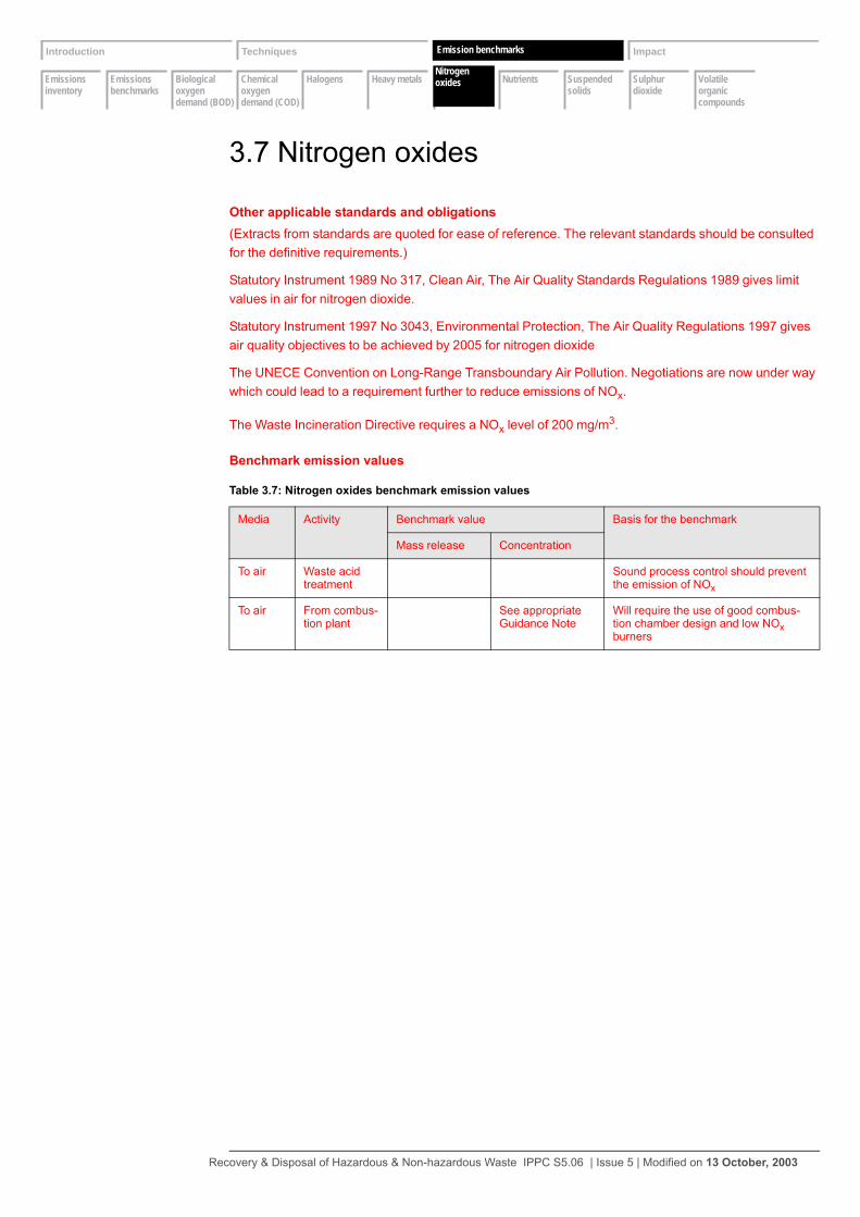
Emissions inventory
Emissions benchmarks
Biological oxygen demand (BOD)
Chemical oxygen demand (COD)
Halogens Heavy metals Nitrogen oxides
Nutrients Suspended solids
Sulphur dioxide
Volatile organic compounds
Introduction Techniques Emissions Impact
Nitrogen oxides
Emission benchmarks
3.7 Nitrogen oxides
Other applicable standards and obligations(Extracts from standards are quoted for ease of reference. The relevant standards should be consulted for the definitive requirements.)
Statutory Instrument 1989 No 317, Clean Air, The Air Quality Standards Regulations 1989 gives limit values in air for nitrogen dioxide.
Statutory Instrument 1997 No 3043, Environmental Protection, The Air Quality Regulations 1997 gives air quality objectives to be achieved by 2005 for nitrogen dioxide
The UNECE Convention on Long-Range Transboundary Air Pollution. Negotiations are now under way which could lead to a requirement further to reduce emissions of NOx.
The Waste Incineration Directive requires a NOx level of 200 mg/m3.
Benchmark emission values
Table 3.7: Nitrogen oxides benchmark emission values
Media Activity Benchmark value Basis for the benchmark
Mass release Concentration
To air Waste acid treatment
Sound process control should prevent the emission of NOx
To air From combus-tion plant
See appropriate Guidance Note
Will require the use of good combus-tion chamber design and low NOx burners
Recovery & Disposal of Hazardous & Non-hazardous Waste IPPC S5.06 | Issue 5 | Modified on 13 October, 2003

Emissions inventory
Emissions benchmarks
Biological oxygen demand (BOD)
Chemical oxygen demand (COD)
Halogens Heavy metals Nitrogen oxides
Nutrients Suspended solids
Sulphur dioxide
Volatile organic compounds
Introduction Techniques Emissions Impact
Nutrients
Emission benchmarks
3.8 Nutrients
Other applicable standards and obligations(Extracts from standards are quoted for ease of reference. The relevant standards should be consulted for the definitive requirements.)
Benchmark emission valuesNitrogen and phosphorus in the effluent will arise from the treatment of nitric acid, ammonia compounds, amines, etc., and phosphoric acid. The benchmarks are obviously important where a treated effluent is being discharged to a watercourse, where account must be taken of nitrate or phosphate vulnerability of the receiving environment.
It is also an important measure where the effluent is to be treated off-site (see Section 2.2.2 on page 68) where the Operator has to assess the off-site treatment against what could be carried out on-site
under BAT criteria.
Table 3.8: Extracts from standards for nutrients
UK water quality objectives Ammonia total(mg/l N, 90%ile)
Non-ionised ammonia (total) (mg/l N, 95%ile)
Class 1 0.25 0.021
Class 2 0.6 0.021
Class 3 1.3 0.021
Class 4 2.5 -
Class 5 9.0 -
Table 3.9: Extracts from standards for nutrients
Designated freshwaters SI 1997/1331
Nitrite(mg/l N)
Ammonia total(mg/l N, 90%ile)
Non-ionised ammonia (total) (mg/l N, 95%ile)
Salmonid imperative: guideline:
-0.150
0.7800.030
0.0210.004
Cyprinid imperative: guideline:
-0.460
0.7800.160
0.0210.004
Recovery & Disposal of Hazardous & Non-hazardous Waste IPPC S5.06 | Issue 5 | Modified on 13 October, 2003
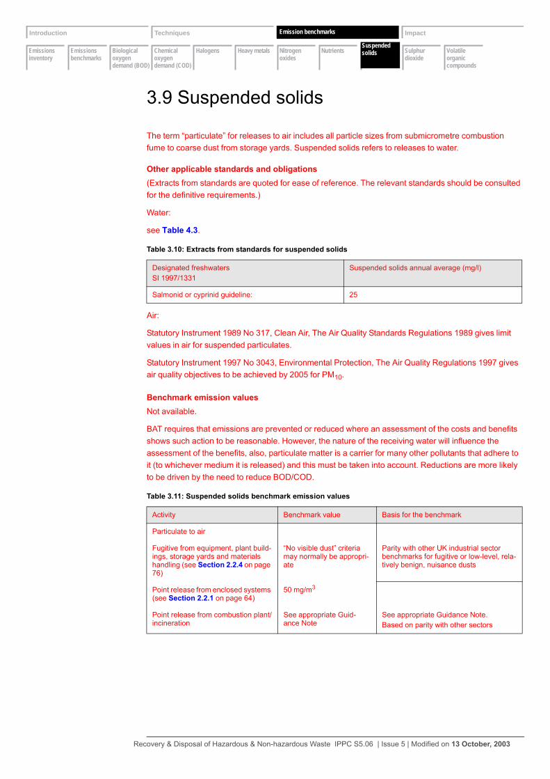
Emissions inventory
Emissions benchmarks
Biological oxygen demand (BOD)
Chemical oxygen demand (COD)
Halogens Heavy metals Nitrogen oxides
Nutrients Suspended solids
Sulphur dioxide
Volatile organic compounds
Introduction Techniques Emissions Impact
Suspended solids
Emission benchmarks
3.9 Suspended solids
The term “particulate” for releases to air includes all particle sizes from submicrometre combustion fume to coarse dust from storage yards. Suspended solids refers to releases to water.
Other applicable standards and obligations(Extracts from standards are quoted for ease of reference. The relevant standards should be consulted for the definitive requirements.)
Water:
see Table 4.3.
Air:
Statutory Instrument 1989 No 317, Clean Air, The Air Quality Standards Regulations 1989 gives limit values in air for suspended particulates.
Statutory Instrument 1997 No 3043, Environmental Protection, The Air Quality Regulations 1997 gives air quality objectives to be achieved by 2005 for PM10.
Benchmark emission valuesNot available.
BAT requires that emissions are prevented or reduced where an assessment of the costs and benefits shows such action to be reasonable. However, the nature of the receiving water will influence the assessment of the benefits, also, particulate matter is a carrier for many other pollutants that adhere to it (to whichever medium it is released) and this must be taken into account. Reductions are more likely to be driven by the need to reduce BOD/COD.
Table 3.10: Extracts from standards for suspended solids
Designated freshwaters SI 1997/1331
Suspended solids annual average (mg/l)
Salmonid or cyprinid guideline: 25
Table 3.11: Suspended solids benchmark emission values
Activity Benchmark value Basis for the benchmark
Particulate to air
Fugitive from equipment, plant build-ings, storage yards and materials handling (see Section 2.2.4 on page 76)
“No visible dust” criteria may normally be appropri-ate
Parity with other UK industrial sector benchmarks for fugitive or low-level, rela-tively benign, nuisance dusts
Point release from enclosed systems (see Section 2.2.1 on page 64)
50 mg/m3
Point release from combustion plant/incineration
See appropriate Guid-ance Note
See appropriate Guidance Note.Based on parity with other sectors
Recovery & Disposal of Hazardous & Non-hazardous Waste IPPC S5.06 | Issue 5 | Modified on 13 October, 2003
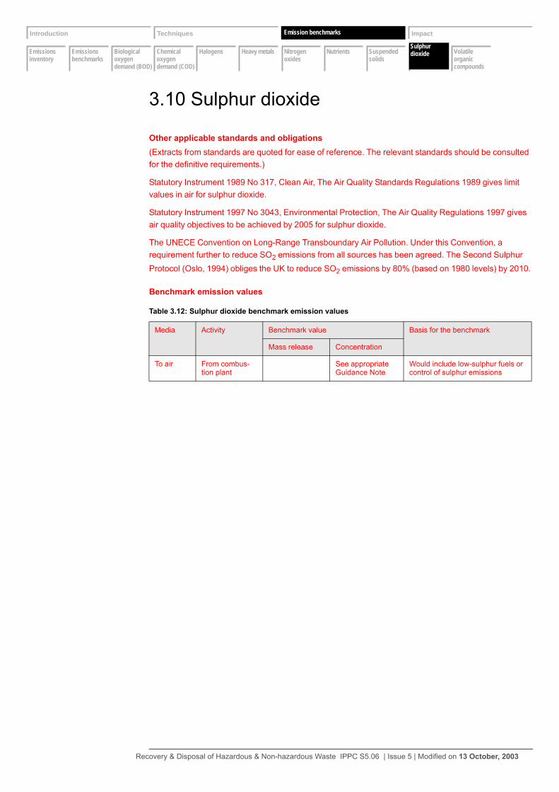
Emissions inventory
Emissions benchmarks
Biological oxygen demand (BOD)
Chemical oxygen demand (COD)
Halogens Heavy metals Nitrogen oxides
Nutrients Suspended solids
Sulphur dioxide
Volatile organic compounds
Introduction Techniques Emissions Impact
Sulphur dioxide
Emission benchmarks
3.10 Sulphur dioxide
Other applicable standards and obligations(Extracts from standards are quoted for ease of reference. The relevant standards should be consulted for the definitive requirements.)
Statutory Instrument 1989 No 317, Clean Air, The Air Quality Standards Regulations 1989 gives limit values in air for sulphur dioxide.
Statutory Instrument 1997 No 3043, Environmental Protection, The Air Quality Regulations 1997 gives air quality objectives to be achieved by 2005 for sulphur dioxide.
The UNECE Convention on Long-Range Transboundary Air Pollution. Under this Convention, a requirement further to reduce SO2 emissions from all sources has been agreed. The Second Sulphur Protocol (Oslo, 1994) obliges the UK to reduce SO2 emissions by 80% (based on 1980 levels) by 2010.
Benchmark emission values
Table 3.12: Sulphur dioxide benchmark emission values
Media Activity Benchmark value Basis for the benchmark
Mass release Concentration
To air From combus-tion plant
See appropriate Guidance Note
Would include low-sulphur fuels or control of sulphur emissions
Recovery & Disposal of Hazardous & Non-hazardous Waste IPPC S5.06 | Issue 5 | Modified on 13 October, 2003
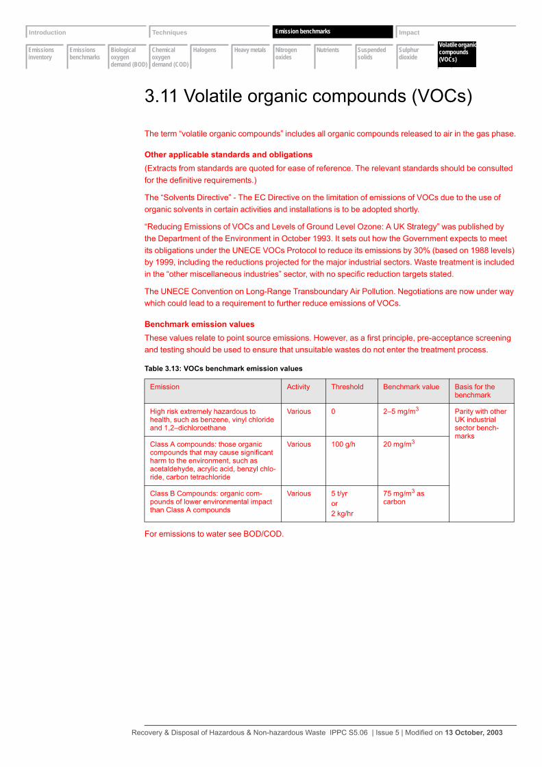
Emissions inventory
Emissions benchmarks
Biological oxygen demand (BOD)
Chemical oxygen demand (COD)
Halogens Heavy metals Nitrogen oxides
Nutrients Suspended solids
Sulphur dioxide
Volatile organic compounds
Introduction Techniques Emissions Impact
Volatile organiccompounds (VOCs)
Emission benchmarks
3.11 Volatile organic compounds (VOCs)
The term “volatile organic compounds” includes all organic compounds released to air in the gas phase.
Other applicable standards and obligations(Extracts from standards are quoted for ease of reference. The relevant standards should be consulted for the definitive requirements.)
The “Solvents Directive” - The EC Directive on the limitation of emissions of VOCs due to the use of organic solvents in certain activities and installations is to be adopted shortly.
“Reducing Emissions of VOCs and Levels of Ground Level Ozone: A UK Strategy” was published by the Department of the Environment in October 1993. It sets out how the Government expects to meet its obligations under the UNECE VOCs Protocol to reduce its emissions by 30% (based on 1988 levels) by 1999, including the reductions projected for the major industrial sectors. Waste treatment is included in the “other miscellaneous industries” sector, with no specific reduction targets stated.
The UNECE Convention on Long-Range Transboundary Air Pollution. Negotiations are now under way which could lead to a requirement to further reduce emissions of VOCs.
Benchmark emission valuesThese values relate to point source emissions. However, as a first principle, pre-acceptance screening and testing should be used to ensure that unsuitable wastes do not enter the treatment process.
For emissions to water see BOD/COD.
Table 3.13: VOCs benchmark emission values
Emission Activity Threshold Benchmark value Basis for the benchmark
High risk extremely hazardous to health, such as benzene, vinyl chloride and 1,2–dichloroethane
Various 0 2–5 mg/m3 Parity with other UK industrial sector bench-marks
Class A compounds: those organic compounds that may cause significant harm to the environment, such as acetaldehyde, acrylic acid, benzyl chlo-ride, carbon tetrachloride
Various 100 g/h 20 mg/m3
Class B Compounds: organic com-pounds of lower environmental impact than Class A compounds
Various 5 t/yror2 kg/hr
75 mg/m3 as carbon
Recovery & Disposal of Hazardous & Non-hazardous Waste IPPC S5.06 | Issue 5 | Modified on 13 October, 2003
Introduction Techniques Emissions Impact
Impactassessment
Waste Management Licensing
Habitats Regulations
Impact assessment
Impact
4 Impact
4.1 Impact assessment
The Operator should assess that the emissions resulting from the proposals for the activities/installation will provide a high level of protection for the environment as a whole, in particular having regard to EQS etc, revisiting the techniques in Section 2 as necessary. The use of IPPC Environmental Assessments for BAT, and the IPPC Environmental Assessments for BAT software tool, and the other tools on the Application CD, will lead the Applicant through the process.
The depth to which the impact assessment should go should be discussed with the Regulator. For some low risk sites the requirements may be reduced.
Recovery & Disposal of Hazardous & Non-hazardous Waste IPPC S5.06 | Issue 5 | Modified on 13 October, 2003
Introduction Techniques Emissions Impact
Impactassessment
Waste Management Licensing
Habitats Regulations
Impact assessment
Impact
Indicative BAT requirements for the impact assessment Provide an assessment of the potential significant environmental effects (including transboundary effects) of the foreseeable emissions.
1 Provide a description, including maps as appropriate, of the receiving environment to identify the receptors of pollution. The extent of the area may cover the local, national and interna-tional (for example, transboundary effects) environment as appropriate.
2 Identify important receptors, which may include: areas of human population including noise or odour-sensitive areas, flora and fauna (that is, Habitat Directive sites, special areas of conser-vation, Sites of Special Scientific Interest (SSSI or in Northern Ireland ASSI) or other sensitive areas), soil, water, that is groundwater (water below the surface of the ground in the saturation zone and in direct contact with the ground and subsoil) and watercourses (for example, ditches, streams, brooks, rivers), air, including the upper atmosphere, landscape, material assets and the cultural heritage.
3 Identify the pathways by which the receptors will be exposed (where not self-evident).
4 Carry out an assessment of the potential impact of the total emissions from the activities on these receptors. IPPC Environmental Assessments for BAT provides a systematic method for doing this and will also identify where modelling needs to be carried out, to air or water, to improve the understanding of the dispersion of the emissions. The assessment will include comparison (see IPPC: A Practical Guide) with:• community EQS levels• other statutory obligations• non-statutory obligations• environmental action levels (EALs) and the other environmental and regulatory parameters
defined in IPPC Environmental Assessments for BAT
5 In particular it will be necessary to demonstrate that an appropriate assessment of vent and chimney heights has been made to ensure that there is adequate dispersion of the minimised emission(s) to avoid exceeding local ground-level pollution thresholds and limit national and transboundary pollution impacts, based on the most sensitive receptor, be it human health, soil or terrestrial ecosystems.
6 Where appropriate, the Operator should also recognise the chimney or vent as an emergency emission point and understand the likely behaviour. Process upsets or equipment failure giving rise to abnormally high emission levels over short periods should be assessed. Even if the Applicant can demonstrate a very low probability of occurrence, the height of the chimney or vent should nevertheless be set to avoid any significant risk to health. The impact of fugitive emissions can also be assessed in many cases.
7 Consider whether the responses to Sections 2 and 3 and this assessment adequately demon-strate that the necessary measures have been taken against pollution, in particular by the application of BAT, and that no significant pollution will be caused. Where there is uncertainty about this, the measures in Section 2 should be revisited as appropriate to make further improvements.
8 Where the same pollutants are being emitted by more than one permitted activity on the instal-lation, the Operator should assess the impact both with and without the neighbouring emissions.
Recovery & Disposal of Hazardous & Non-hazardous Waste IPPC S5.06 | Issue 5 | Modified on 13 October, 2003

Introduction Techniques Emissions Impact
Impactassessment
Waste Management Licensing
Habitats Regulations
The Waste Management Licensing
Impact
4.2 The Waste Management Licensing Regulations
Indicative BAT requirements for the Waste Management Licensing Regulations Explain how the information provided in other parts of the application also demonstrates that the requirements of the relevant objectives of the Waste Management Licensing Regulations 1994 have been addressed, or provide additional information in this respect.
1 In relation to activities involving the disposal or recovery of waste, the Regulators are required to exercise their functions for the purpose of achieving the relevant objectives as set out in Schedule 4 of the Waste Management Licensing Regulations 1994. (For the equivalent Regu-lations in Scotland and Northern Ireland, see Appendix 2.)
2 The relevant objectives, contained in paragraph 4, Schedule 4 of the Waste Management Licensing Regulations 1994 (SI 1994/1056 as amended) are extensive, but will only require attention for activities that involve the recovery or disposal of waste. Paragraph 4 (1) is as follows:• ensuring the waste is recovered or disposed of without endangering human health and with-
out using process or methods which could harm the environment and in particular without:– risk to water, air, soil, plants or animals or– causing nuisance through noise or odours or– adversely affecting the countryside or places of special interest
• implementing, as far as material, any plan made under the plan-making provisions
3 The application of BAT is likely to already address risks to water, air, soil, plants or animals, odour nuisance and some aspects of effects on the countryside. It will, however, be necessary for the Operator briefly to consider each of these objectives individually and provide a comment on how they are being addressed by your proposals. It is also necessary to ensure that any places of special concern that could be affected, such as SSSIs, are identified and commented upon although, again, these may have been addressed in your assessment for BAT, in which case a cross-reference may suffice.
4 Operators should identify any development plans made by the local planning authority, including any waste local plan, and comment on the extent to which the proposals accord with the contents of any such plan (see Section 2.6 on page 91).
Recovery & Disposal of Hazardous & Non-hazardous Waste IPPC S5.06 | Issue 5 | Modified on 13 October, 2003
Introduction Techniques Emissions Impact
Impactassessment
Waste Management Licensing
Habitats Regulations
The Habitats Regulations
Impact
4.3 The Habitats Regulations
Indicative BAT requirements for the Habitats Regulations Provide an assessment of whether the installation is likely to have a significant effect on a European site in the UK and if it is, provide an assessment of the implications of the installation for that site, for the purposes of the Conservation (Natural Habitats etc) Regulations 1994 (SI 1994/2716).Your response should cover all relevant issues pertinent to your installation, including those below. In doing so you should justify your proposals against any indicative requirements stated.
1 An application for an IPPC Permit will be regarded as a new plan or project for the purposes of the Habitats Regulations (for the equivalent Regulations in Scotland and Northern Ireland see Appendix 2). Therefore, Operators should provide an initial assessment of whether the instal-lation is likely to have a significant effect on any European site in the UK (either alone or in combination with other relevant plans or projects) and, if so, an initial assessment of the impli-cations of the installation for any such site. The application of BAT is likely to have gone some way towards addressing the potential impact of the installation on European sites and putting into place techniques to avoid any significant effects. The Operator should provide a descrip-tion of how the BAT assessment has specifically taken these matters into account, bearing in mind the conservation objectives of any such site.
2 European sites are defined in Regulation 10 of the Habitats Regulations to include Special Areas of Conservation (SACs); sites of community importance (sites that have been selected as candidate SACs by member states and adopted by the European Commission, but which are not yet formally classified); and Special Protection Areas (SPAs). It is also Government policy (set out in PPG 9 on nature conservation) that potential SPAs and candidate SACs should be considered to be European sites for the purposes of Regulation 10.
3 Information on the location of European sites and their conservation objectives is available from: • English Nature (01733 455000), www.english-nature.org.uk• Countryside Council for Wales (01248 385620), www.ccw.gov.uk• Scottish Natural Heritage (0131 447 4784), www.snh.org.uk• Joint Nature Conservation Committee (01733 866852), www.jncc.gov.uk• Environment and Heritage Service, Northern Ireland, www.ehsni.gov.uk• Environment and Heritage Service, Northern Ireland (02890254754), www.ehsni.gov.uk
4 The Regulator will need to consider the Operator's initial assessment. If it concludes that the installation is likely to have a significant effect on a European site, then the Regulator will need to carry out an “appropriate assessment” of the implications of the installation in view of that site's conservation objectives. The Regulations impose a duty on the Regulator to carry out these assessments, so it cannot rely on the Operator's initial assessments. Therefore the Regulator must be provided with any relevant information upon which the Operator’s assess-ment is based.
5 Note that in many cases the impact of the Habitats Regulations will have been considered at the planning application stage, in which case the Regulator should be advised of the details.
Recovery & Disposal of Hazardous & Non-hazardous Waste IPPC S5.06 | Issue 5 | Modified on 13 October, 2003
References
For a full list of available Technical Guidance see Appendix A of the Guide for Applicants or visit the Environment Agency Website http://www.environment-agency.gov.uk. Many of the references below are being made available free of charge for viewing or download on the Website. The same information can also be accessed via the NIEHS web site www.ehsni.gov.uk. Most titles will also be available in hard copy from The Stationery Office (TSO). Some existing titles are not yet available on the Website but can be obtained from TSO.
Ref 1 Guidance for applicants
• IPPC Part A(1) Installations: Guide for (Applicants England and Wales) (includes Preparation of a Site Report in a Permit Application) (EA website).
Ref 2 Assessment methodologies:
• E1 BPEO Assessment Methodology for IPC
• IPPC Environmental Assessments for BAT H1
Ref 3 Waste minimisation support references
• Environment Agency web site. Waste minimisation information accessible via: www.environment-agency.gov.uk/subjects/waste/131528
• Waste Minimisation – an environmental good practice guide for industry (helps industry to minimise waste and achieve national environmental goals). Available free to companies who intend to undertake a waste reduction programme (tel: 0345 33 77 00)
• Profiting from Pollution Prevention – 3Es methodology (emissions, efficiency, economics). Video and A4 guide aimed at process industries. Available from Environment Agency, North East region (tel: 0113 244 0191, ask for Regional PIR)
• Waste Minimisation Interactive Tools (WIMIT). Produced in association with Envirowise and the BOC Foundation (a software tool designed for small and medium businesses.). Available free from The Environmental Helpline (tel: 0800 585794)
• ENVIROWISE. A joint DTI/DEFRA programme, with over 200 separate case studies, good practice guides, leaflets, flyers, software tools and videos covering 12 industry sectors, packaging, solvents and the generic areas of waste minimisation and cleaner technology. ENVIROWISE is accessible via a FREE and confidential helpline (tel: 0800 585794) or via the web site www.envirowise.gov.uk
• Increased Profit Through Improved Materials Additions: Management/Technical Guide, ENVIROWISE, GG194/195
• Waste Management Information Bureau. The UK's national referral centre for help on the full range of waste management issues. It produces a database called Waste Info, which is available for on-line searching and on CD-ROM. Short enquiries are free (tel: 01235 463162)
• Waste Minimisation – Institution of Chemical Engineers Training Package E07. Basic course which contains guide, video, slides, OHPs etc. (tel: 01788 578214)
• BIO-WISE - profiting through industrial biotechnology. A DTI programme providing free advice and information about how biotechnology can be used within manufacturing industry. Case studies, guides website and Helpline 0800 432100. dti.gov.uk/biowise (leather guide GG237 and case study 11
Ref 4 Waste storage references:
• Storage of flammable liquids in containers, HSG51,HSE Books, ISBN 0-7176-1471-9
• Chemical Warehousing – the storage of packaged dangerous substances, HSG71,HSE Books, ISBN 07176-1484-0
• Storage of flammable liquids in tanks, HSG 716S
• The Storage and Handling of Organic Peroxides, CS21 HSE Books, ISBN 0-7176-2403-X
• The Safe Use and Handling of Flammable Liquids. HSG 140
• Designing and Operating Safe Chemical Reaction Processes. HMSO 2000. HSG 143. ISBN 0-7176-1051-9
• Storage and Handling of Corrosive Liquids, ITN/IPC4/02, Environment Agency
• The Storage and Handling of Drums and Intermediate Bulk Containers PPG 26, Environment Agency
Ref 5 Water efficiency references:
• Simple measures restrict water costs, ENVIROWISE, GC22
Recovery & Disposal of Hazardous & Non-hazardous Waste IPPC S5.06 | Issue 5 | Modified on 13 October, 2003
• Effluent costs eliminated by water treatment,ENVIROWISE, GC24
• Saving money through waste minimisation: Reducing water use, ENVIROWISE, GG26
• ENVIROWISE Helpline 0800 585794
• Optimum use of water for industry and agriculture dependent on direct abstraction: Best practice manual. R&D technical report W157, Environment Agency (1998), WRc Dissemination Centre, Swindon (tel: 01793 865012)
• Cost-effective Water Saving Devices and Practices ENVIROWISE GG067
• Water and Cost Savings from Improved Process Control ENVIROWISE GC110
• Tracking Water Use to Cut Costs ENVIROWISE GG152
Ref 6 Releases to air references:
• BREF on Waste Water and Waste Gas Treatment.
• A1 Guidance on effective flaring in the gas, petroleum etc. industries, 1993, ISBN 0-11-752916-8
• A2 Pollution abatement technology for the reduction of solvent vapour emissions, 1994, £5.00, 0-11-752925-7
• A3 Pollution abatement technology for particulate and trace gas removal, 1994, £5.00, 0-11-752983-4
• Part B PG1/3 Boilers and Furnaces 20-50 MW net thermal input (ISBN 0-11-753146-4-7)
• Part B PG1/4 Gas Turbines 20-50 MW net thermal input (ISBN 0-11-753147-2
Ref 7 Releases to water references
• BREF on Waste Water and Waste Gas Treatment
• A4 Effluent Treatment Techniques, TGN A4, Environment Agency, ISBN 0-11-310127-9 (EA website)
• Pollution Prevention Guidance Note – Above-ground oil storage tanks, PPG 2, Environment Agency, gives information on tanks and bunding which have general relevance beyond just oil (EA website)
• Construction of bunds for oil storage tanks, Mason, P. A, Amies, H. J, Sangarapillai, G. Rose, Construction Industry Research and Information Association (CIRIA), Report 163, 1997, CIRIA, 6 Storey’s Gate, Westminster, London SW1P 3AU. Abbreviated versions are also available for masonry and concrete bunds (www.ciria.org.uk on-line purchase)
• Policy and Practice for the Protection of Groundwater (PPPG) (EA website)
• Choosing Cost-effective Pollution Control ENVIROWISE GG109
• Cost-effective Separation Technologies for Minimising Wastes and Effluents ENVIROWISE GG037
• Cost-effective Membrane Technologies for Minimising: Wastes and Effluents ENVIROWISE GG044
Ref 8 Waste management references
• Investigation of the criteria for, and guidance on, the landspreading of industrial wastes – final report to the DEFRA, the Environment Agency and MAFF, May 1998
Ref 9 Energy references
• (Interim) Energy Efficiency Guidance,(available as draft Horizontal Guidance Note IPPC H2) (www.environment-agency.gov.uk)
Ref 10 COMAH guides
• A Guide to the Control of Major Accident Hazards Regulations 1999, Health and Safety Executive (HSE) Books L111, 1999, ISBN 0 07176 1604 5
• Preparing Safety Reports: Control of Major Accident Hazards Regulations 1999, HSE Books HS(G)190, 1999
• Emergency Planning for Major Accidents: Control of Major Accident Hazards Regulations 1999, HSE Books HS(G)191, 1999
• Guidance on the Environmental Risk Assessment Aspects of COMAH Safety Reports, Environment Agency, 1999 (EA website)
• Guidance on the Interpretation of Major Accidents to the Environment for the Purposes of the COMAH Regulations, DEFRA, 1999, ISBN 753501 X, available from the Stationery Office
Ref 11 Monitoring Guidance
• MCERTS approved equipment link via www.environment-agency.gov.uk/business/mcerts
• M1 Sampling facility requirements for the monitoring of particulates in gaseous releases to atmosphere, March 1993, £5.00, ISBN 0-11-752777-7
• M3 Standards for IPC Monitoring Part 1: Standards, organisations and the measurement infrastructure, August 1995, £11.00, ISBN 0-11-753133-2
• M4 Standards for IPC Monitoring Part 2: Standards in support of IPC Monitoring, revised 1998
• Direct Toxicity Assessment for Effluent Control Technical Guidance (2000), UKWIR 00/TX/02/07
Ref 12 Odour references
Recovery & Disposal of Hazardous & Non-hazardous Waste IPPC S5.06 | Issue 5 | Modified on 13 October, 2003

• Odour Assessment and Control – Guidance for Regulators and Industry (joint agencies guidance in preparation)
• Integrated Pollution Prevention and Control (IPPC) IPPC Horizontal Guidance Note for Odour - H4: Parts 1 and 2
Ref 13 Noise references:
• H3 Horizontal Guidance for Noise Part 1Regulation and Permitting
• H3 Horizontal Guidance for Noise Part 2 Assessment and Control
Ref 14 Closure references
• Working at Construction and Demolition-sites (PPG 6) (EA website)
Ref 15 Fire Fighting
• BS 5908: Code of Practice for Fire Precautions in the Chemical and Allied Industries
• PPG 18 - Managing Fire-water and major spillages, Environment Agency Pollution Prevention Guidance Note (see Ref 10)
Ref 16 Directives
• Hazardous waste incineration Directive (1994/67/EC)
• Waste incineration Directive (2000/76/EC)
• Large Combustion Plant Directives (1988/609/EEC)
• Habitiats Directive (92/43/EC)
Recovery & Disposal of Hazardous & Non-hazardous Waste IPPC S5.06 | Issue 5 | Modified on 13 October, 2003

Abbreviations
BAT Best Available Techniques – see IPPC A Practical Guide or the Regulations for further definition
BAT Criteria The criteria to be taken into account when assessing BAT, given in Schedule 2 of the PPC Regulations
BOD Biochemical Oxygen DemandBPEO Best Practical Environmental OptionBREF BAT Reference DocumentCEM Continuous Emissions MonitoringCHP Combined heat and power plantCOD Chemical Oxygen DemandELV Emission Limit ValueEMS Environmental Management SystemEQS Environmental Quality StandardETP Effluent treatment plantITEQ International Toxicity EquivalentsMCERTS Monitoring Certification SchemeNIEHS Northern Ireland Environment and Heritage ServiceSAC Special Areas of ConservationSECp Specific Energy consumptionSED Solvent Emissions Directive
SPA Special Protection AreaTSS Suspended solidsTOC Total Organic CarbonVOC Volatile organic compounds WML Waste Management Licence
Recovery & Disposal of Hazardous & Non-hazardous Waste IPPC S5.06 | Issue 5 | Modified on 13 October, 2003
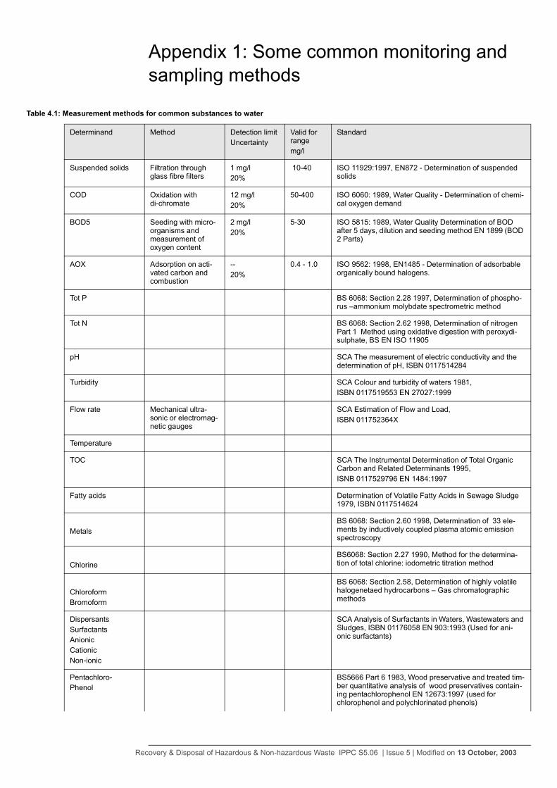
Appendix 1: Some common monitoring and sampling methods
Table 4.1: Measurement methods for common substances to water
Determinand Method Detection limitUncertainty
Valid for rangemg/l
Standard
Suspended solids Filtration through glass fibre filters
1 mg/l20%
10-40 ISO 11929:1997, EN872 - Determination of suspended solids
COD Oxidation with di-chromate
12 mg/l20%
50-400 ISO 6060: 1989, Water Quality - Determination of chemi-cal oxygen demand
BOD5 Seeding with micro-organisms and measurement of oxygen content
2 mg/l20%
5-30 ISO 5815: 1989, Water Quality Determination of BOD after 5 days, dilution and seeding method EN 1899 (BOD 2 Parts)
AOX Adsorption on acti-vated carbon and combustion
--20%
0.4 - 1.0 ISO 9562: 1998, EN1485 - Determination of adsorbable organically bound halogens.
Tot P BS 6068: Section 2.28 1997, Determination of phospho-rus –ammonium molybdate spectrometric method
Tot N BS 6068: Section 2.62 1998, Determination of nitrogen Part 1 Method using oxidative digestion with peroxydi-sulphate, BS EN ISO 11905
pH SCA The measurement of electric conductivity and the determination of pH, ISBN 0117514284
Turbidity SCA Colour and turbidity of waters 1981,ISBN 0117519553 EN 27027:1999
Flow rate Mechanical ultra-sonic or electromag-netic gauges
SCA Estimation of Flow and Load, ISBN 011752364X
Temperature
TOC SCA The Instrumental Determination of Total Organic Carbon and Related Determinants 1995,ISNB 0117529796 EN 1484:1997
Fatty acids Determination of Volatile Fatty Acids in Sewage Sludge 1979, ISBN 0117514624
MetalsBS 6068: Section 2.60 1998, Determination of 33 ele-ments by inductively coupled plasma atomic emission spectroscopy
ChlorineBS6068: Section 2.27 1990, Method for the determina-tion of total chlorine: iodometric titration method
ChloroformBromoform
BS 6068: Section 2.58, Determination of highly volatile halogenetaed hydrocarbons – Gas chromatographic methods
Dispersants SurfactantsAnionicCationicNon-ionic
SCA Analysis of Surfactants in Waters, Wastewaters and Sludges, ISBN 01176058 EN 903:1993 (Used for ani-onic surfactants)
Pentachloro-Phenol
BS5666 Part 6 1983, Wood preservative and treated tim-ber quantitative analysis of wood preservatives contain-ing pentachlorophenol EN 12673:1997 (used for chlorophenol and polychlorinated phenols)
Recovery & Disposal of Hazardous & Non-hazardous Waste IPPC S5.06 | Issue 5 | Modified on 13 October, 2003
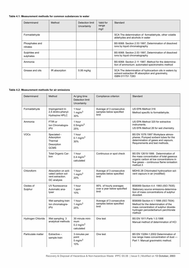
Formaldehyde SCA The determination of formaldehyde, other volatile aldehydes and alcohols in water
Phosphates andnitrates
BS 6068: Section 2.53 1997, Determination of dissolved ions by liquid chromatography
Sulphites and sulphates
BS 6068: Section 2.53 1997, Determination of dissolved ions by liquid chromatography
Ammonia BS 6068: Section 2.11 1987, Method for the determina-tion of ammonium: automated spectrometric method
Grease and oils IR absorption 0.06 mg/kg SCA The determination of hydrocarbon oils in waters by solvent extraction IR absorption and gravimetry, ISBN 011751 7283
Table 4.1: Measurement methods for common substances to water
Determinand Method Detection limitUncertainty
Valid for rangemg/l
Standard
Table 4.2: Measurement methods for air emissions
Determinand Method Av’ging timeDetection limitUncertainty
Compliance criterion Standard
Formaldehyde Impingement In 2,4 dinitro-phenyl-Hydrazine HPLC
1 hour1 mg/m3
30%
Average of 3 consecutive samples below specified limit
US EPA Method 316Method specific to formaldehyde.
Ammonia FTIR orIon Chromatogra-phy
1 hour0.5mg/m3
25%
US EPA Method 320 for extractive instruments.US EPA Method 26 for wet chemistry.
VOCs Speciated - AdsorptionThermal DesorptionGCMS
1 hour0.1 mg/m3
30%
BS EN 1076:1997 Workplace atmos-pheres. Pumped sorbent tubes for the determination of gases and vapours. Requirements and test methods.
Total Organic Car-bon
1 hour0.4 mg/m3
calculated
Continuous or spot check BS EN 12619:1999. Determination of the mass concentration of total gaseous organic carbon at low concentrations in flue gases – continuous flame ionisation method.3
Chloroform Absorption on acti-vated carbon sol-vent extraction.GC analysis
1 hour1 mg/m3
20%
Average of 3 consecutive samples below specified limit
MDHS 28 Chlorinated hydrocarbon sol-vent vapours in air (modified)
Oxides ofSulphur
UV fluorescenceAutomatic ana-lyser
1 hour1 ppm10%
95% of hourly averages over a year below specified limit
BS6069 Section 4.4 :1993 (ISO 7935)Stationary source emissions-determina-tion of mass concentrations of sulphur dioxide4.
Wet sampling trainIon chromatogra-phy
1 hour1 mg/m3
25%
Average of 3 consecutive samples below specified limit
BS6069 Section 4.1:1998 (ISO 7934)Method for the determination of the mass concentration of sulphur dioxide-hydrogen peroxide/barium perchlorate method
Hydrogen Chloride Wet sampling 3 analytical methods
30 minute mini-mum0.2 mg/m3
calculated
One test BS EN 1911:Parts 1-3:1998Manual method of determination of HCl
Particulate matter Extractive –sample train
3 minutes per point5 mg/m3
10%
One test BS EN 13284-1:2002 Determination of low range mass concentration of dust —Part 1: Manual gravimetric method.
Recovery & Disposal of Hazardous & Non-hazardous Waste IPPC S5.06 | Issue 5 | Modified on 13 October, 2003
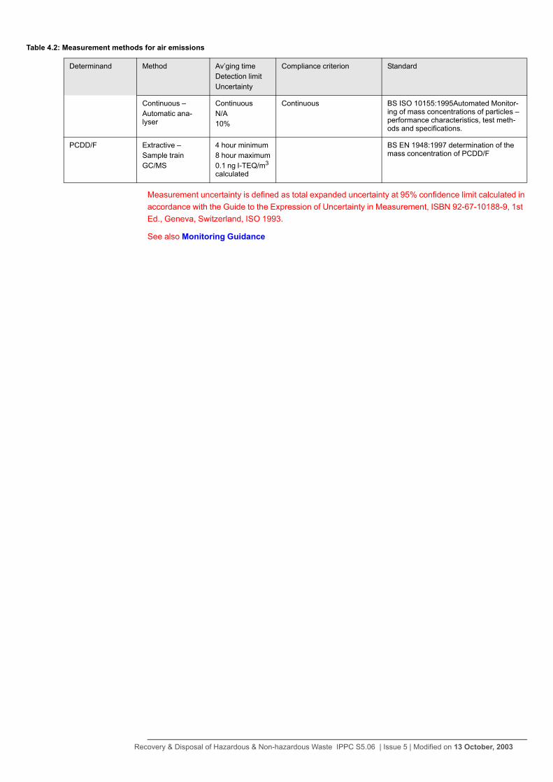
Measurement uncertainty is defined as total expanded uncertainty at 95% confidence limit calculated in accordance with the Guide to the Expression of Uncertainty in Measurement, ISBN 92-67-10188-9, 1st Ed., Geneva, Switzerland, ISO 1993.
See also Monitoring Guidance
Continuous –Automatic ana-lyser
ContinuousN/A10%
Continuous BS ISO 10155:1995Automated Monitor-ing of mass concentrations of particles – performance characteristics, test meth-ods and specifications.
PCDD/F Extractive –Sample trainGC/MS
4 hour minimum8 hour maximum0.1 ng I-TEQ/m3 calculated
BS EN 1948:1997 determination of the mass concentration of PCDD/F
Table 4.2: Measurement methods for air emissions
Determinand Method Av’ging timeDetection limitUncertainty
Compliance criterion Standard
Recovery & Disposal of Hazardous & Non-hazardous Waste IPPC S5.06 | Issue 5 | Modified on 13 October, 2003
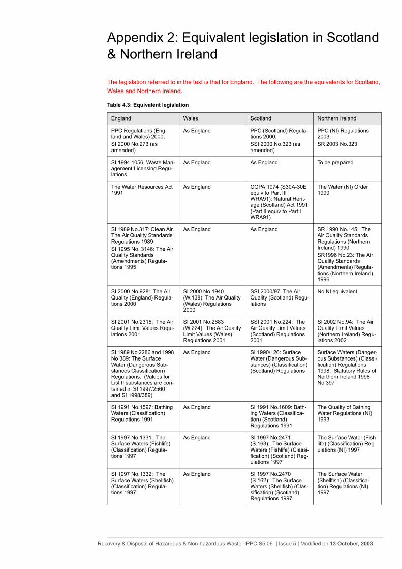
Appendix 2: Equivalent legislation in Scotland & Northern Ireland
The legislation referred to in the text is that for England. The following are the equivalents for Scotland, Wales and Northern Ireland.
Table 4.3: Equivalent legislation
England Wales Scotland Northern Ireland
PPC Regulations (Eng-land and Wales) 2000,SI 2000 No.273 (as amended)
As England PPC (Scotland) Regula-tions 2000,SSI 2000 No.323 (as amended)
PPC (NI) Regulations 2003,SR 2003 No.323
SI:1994 1056: Waste Man-agement Licensing Regu-lations
As England As England To be prepared
The Water Resources Act 1991
As England COPA 1974 (S30A-30E equiv to Part III WRA91): Natural Herit-age (Scotland) Act 1991 (Part II equiv to Part I WRA91)
The Water (NI) Order 1999
SI 1989 No.317: Clean Air, The Air Quality Standards Regulations 1989SI 1995 No. 3146: The Air Quality Standards (Amendments) Regula-tions 1995
As England As England SR 1990 No.145: The Air Quality Standards Regulations (Northern Ireland) 1990SR1996 No.23: The Air Quality Standards (Amendments) Regula-tions (Northern Ireland) 1996
SI 2000 No.928: The Air Quality (England) Regula-tions 2000
SI 2000 No.1940 (W.138): The Air Quality (Wales) Regulations 2000
SSI 2000/97: The Air Quality (Scotland) Regu-lations
No NI equivalent
SI 2001 No.2315: The Air Quality Limit Values Regu-lations 2001
SI 2001 No.2683 (W.224): The Air Quality Limit Values (Wales) Regulations 2001
SSI 2001 No.224: The Air Quality Limit Values (Scotland) Regulations 2001
SI 2002 No.94: The Air Quality Limit Values (Northern Ireland) Regu-lations 2002
SI 1989 No 2286 and 1998 No 389: The Surface Water (Dangerous Sub-stances Classification) Regulations. (Values for List II substances are con-tained in SI 1997/2560 and SI 1998/389)
As England SI 1990/126: Surface Water (Dangerous Sub-stances) (Classification) (Scotland) Regulations
Surface Waters (Danger-ous Substances) (Classi-fication) Regulations 1998. Statutory Rules of Northern Ireland 1998 No 397
SI 1991 No.1597: Bathing Waters (Classification) Regulations 1991
As England SI 1991 No.1609: Bath-ing Waters (Classifica-tion) (Scotland) Regulations 1991
The Quality of Bathing Water Regulations (NI) 1993
SI 1997 No.1331: The Surface Waters (Fishlife) (Classification) Regula-tions 1997
As England SI 1997 No.2471 (S.163): The Surface Waters (Fishlife) (Classi-fication) (Scotland) Reg-ulations 1997
The Surface Water (Fish-life) (Classification) Reg-ulations (NI) 1997
SI 1997 No.1332: The Surface Waters (Shellfish) (Classification) Regula-tions 1997
As England SI 1997 No.2470 (S.162): The Surface Waters (Shellfish) (Clas-sification) (Scotland) Regulations 1997
The Surface Water (Shellfish) (Classifica-tion) Regulations (NI) 1997
Recovery & Disposal of Hazardous & Non-hazardous Waste IPPC S5.06 | Issue 5 | Modified on 13 October, 2003

SI 1994 No.2716: The Conservation (Natural Habitats, etc) Regulations
As England As England Conservation (Natural Habitats etc) Regulations (Northern Ireland) 1995
SI 1999 No.743: Control of Major Accident Haz-ards Regulations (COMAH) 1999
As England As England SR 2000 No.93: Control of Major Accident Haz-ards Regulations (North-ern Ireland) 2000
SI 1998 No.2746: The Groundwater Regulations 1998
As England As England SR 1998 No.401. The Groundwater Regula-tions (Northern IrelandI) 1998
Table 4.3: Equivalent legislation
England Wales Scotland Northern Ireland
Recovery & Disposal of Hazardous & Non-hazardous Waste IPPC S5.06 | Issue 5 | Modified on 13 October, 2003
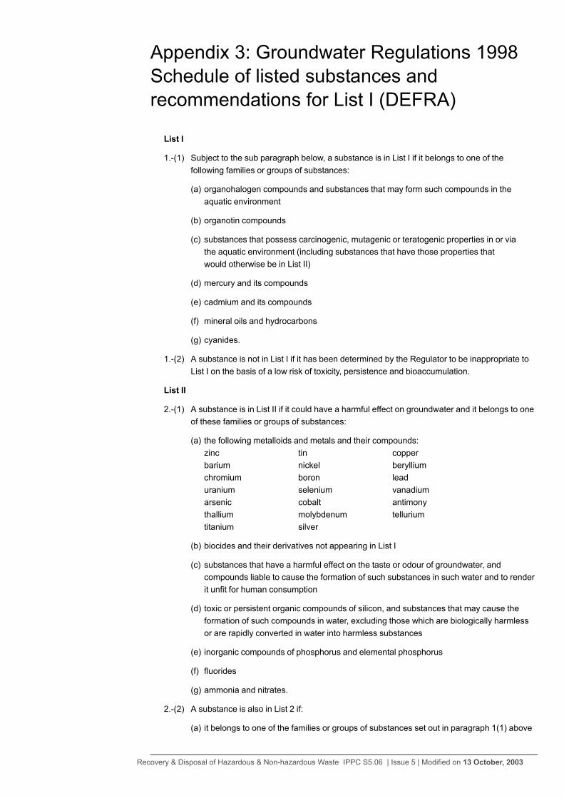
Appendix 3: Groundwater Regulations 1998 Schedule of listed substances and recommendations for List I (DEFRA)
List I
1.-(1) Subject to the sub paragraph below, a substance is in List I if it belongs to one of thefollowing families or groups of substances:
(a) organohalogen compounds and substances that may form such compounds in theaquatic environment
(b) organotin compounds
(c) substances that possess carcinogenic, mutagenic or teratogenic properties in or viathe aquatic environment (including substances that have those properties thatwould otherwise be in List II)
(d) mercury and its compounds
(e) cadmium and its compounds
(f) mineral oils and hydrocarbons
(g) cyanides.
1.-(2) A substance is not in List I if it has been determined by the Regulator to be inappropriate toList I on the basis of a low risk of toxicity, persistence and bioaccumulation.
List II
2.-(1) A substance is in List II if it could have a harmful effect on groundwater and it belongs to oneof these families or groups of substances:
(a) the following metalloids and metals and their compounds:zinc tin copperbarium nickel berylliumchromium boron leaduranium selenium vanadiumarsenic cobalt antimonythallium molybdenum telluriumtitanium silver
(b) biocides and their derivatives not appearing in List I
(c) substances that have a harmful effect on the taste or odour of groundwater, andcompounds liable to cause the formation of such substances in such water and to renderit unfit for human consumption
(d) toxic or persistent organic compounds of silicon, and substances that may cause theformation of such compounds in water, excluding those which are biologically harmlessor are rapidly converted in water into harmless substances
(e) inorganic compounds of phosphorus and elemental phosphorus
(f) fluorides
(g) ammonia and nitrates.
2.-(2) A substance is also in List 2 if:
(a) it belongs to one of the families or groups of substances set out in paragraph 1(1) above
Recovery & Disposal of Hazardous & Non-hazardous Waste IPPC S5.06 | Issue 5 | Modified on 13 October, 2003

(b) it has been determined by the Regulator to be inappropriate to List I under paragraph1(2); and
(c) it has been determined by the Regulator to be in inappropriate to List II having regard totoxicity, persistence and bioaccumulation.
3.-(1) The Secretary of State or Scottish Ministers may review any decision of the Regulator inrelation to the exercise of its powers under the paragraphs above.
3.-(2) The Secretary of State or Scottish Minister shall notify the Regulator of his decision followinga review under List 1 sub paragraph 1 above and it shall be the duty of the Regulator to giveeffect to that decision.
4.- The Regulator shall from time to time publish a summary of the effect of its determinationsunder this Schedule in such manner as it considers appropriate and shall make copies ofany such summary available to the public free of charge.
List of substances recommended to be confirmed as List I
- as recommended by the Joint Agency Groundwater Directive Advisory Group.
Aldrin Diuron
Atrazine Endosulfan
Azinphos-ethyl Fenitrothion
Bromoxynil (as Bromoxynil-phenol) Fenthion
Bromoxynil octanoate Heptachlor
Cadmium Hexachlorobenzene
2-Chloroaniline Hexachlorobutadiene (HCBD)
Chlorobenzene Hexachlorocyclohexane
Chlordane Hexachloroethane
Chloro-2,4-dinitrobenzene Hexachloronorbornadiene
Chlorfenvinphos Hexaconazole
4-Chloro-3-methylphenol 3-Iodo-2-proponyl n-butyl carbamate (IPBC)
Chloro-2-nitrobenzene Linuron
Chloro-3-nitrobenzene Malathion
Chloro-4-nitrobenzene Mercury
2-Chlorophenol Mevinphos
Chlorothalonil Oxydemeton-methyl
2-Chlorotoluene Parathion
a-Chlorotoluene Parathion-methyl
Chlorpyrifos Pentachlorobenzene
Coumaphos Pentachloroethane
Cypermethrin Pentachlorophenol (PCP)
DDT Permethrin
Demeton Propanil
Diazinon Simazine
Dibutyl bis(oxylauroyl)tin Tetrabutyltin
Dichlofluanid 1,2,4,5-Tetrachlorobenzene
Recovery & Disposal of Hazardous & Non-hazardous Waste IPPC S5.06 | Issue 5 | Modified on 13 October, 2003

Dichloroaniline Tetrachloroethylene
1,2-Dichlorobenzene Triazophos
1,3-Dichlorobenzene Tributyl tin oxide (TBTO)
1,4-Dichlorobenzene Tributyl-phosphate
Dichloronitrobenzene (all isomers) Trichlorfon
2,4-Dichlorophenol 1,2,4-Trichlorobenzene
1,3-Dichloropropene Trichloroethylene
Dichlorprop Trichlorophenol (all isomers)
Dichlorvos Trifluralin
Dicofol Triphenyl tin oxide (TPTO)
Dieldrin Triphenyl-phosphate
Dimethoate
Recovery & Disposal of Hazardous & Non-hazardous Waste IPPC S5.06 | Issue 5 | Modified on 13 October, 2003

Recovery & Disposal of Hazardous & Non-hazardous Waste IPPC S5.06 | Issue 5 | Modified on 13 October, 2003