sectional 3298 xs group close coupled sizes1x11 -5 and … · sectional 3298 xs group close coupled...
TRANSCRIPT
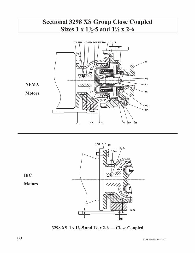
Sectional 3298 XS Group Close Coupled
Sizes 1 x 1 12-5 and 1½ x 2-6
92 3298 Family Rev. 4/07
NEMA
Motors
IEC
Motors
3298 XS 1 x 1 12-5 and 1½ x 2-6 — Close Coupled
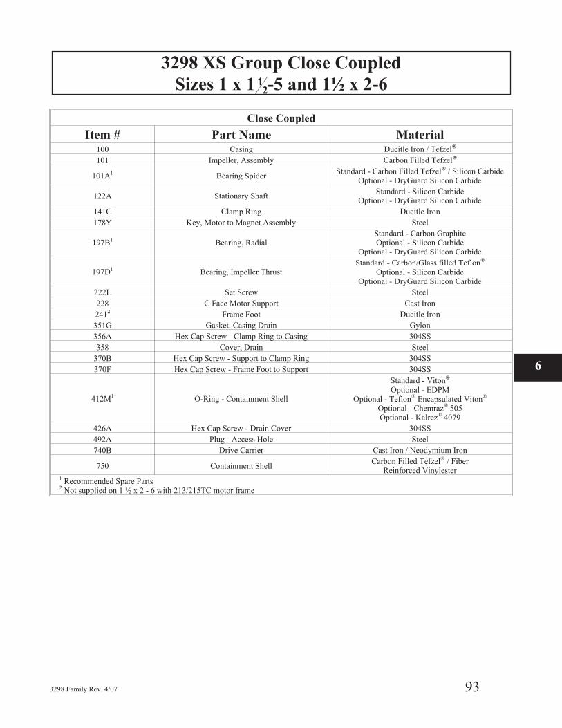
3298 XS Group Close Coupled
Sizes 1 x 1 12-5 and 1½ x 2-6
3298 Family Rev. 4/07 93
Close Coupled
Item # Part Name Material100 Casing Ducitle Iron / Tefzel®
101 Impeller, Assembly Carbon Filled Tefzel®
101A1 Bearing SpiderStandard - Carbon Filled Tefzel® / Silicon Carbide
Optional - DryGuard Silicon Carbide
122A Stationary ShaftStandard - Silicon Carbide
Optional - DryGuard Silicon Carbide
141C Clamp Ring Ducitle Iron
178Y Key, Motor to Magnet Assembly Steel
197B1 Bearing, RadialStandard - Carbon GraphiteOptional - Silicon Carbide
Optional - DryGuard Silicon Carbide
197D1 Bearing, Impeller ThrustStandard - Carbon/Glass filled Teflon®
Optional - Silicon CarbideOptional - DryGuard Silicon Carbide
222L Set Screw Steel
228 C Face Motor Support Cast Iron
2412 Frame Foot Ducitle Iron
351G Gasket, Casing Drain Gylon
356A Hex Cap Screw - Clamp Ring to Casing 304SS
358 Cover, Drain Steel
370B Hex Cap Screw - Support to Clamp Ring 304SS
370F Hex Cap Screw - Frame Foot to Support 304SS
412M1 O-Ring - Containment Shell
Standard - Viton®
Optional - EDPMOptional - Teflon® Encapsulated Viton®
Optional - Chemraz® 505Optional - Kalrez® 4079
426A Hex Cap Screw - Drain Cover 304SS
492A Plug - Access Hole Steel
740B Drive Carrier Cast Iron / Neodymium Iron
750 Containment ShellCarbon Filled Tefzel® / Fiber
Reinforced Vinylester1 Recommended Spare Parts2 Not supplied on 1 ½ x 2 - 6 with 213/215TC motor frame
6
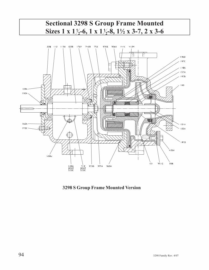
Sectional 3298 S Group Frame Mounted
Sizes 1 x 1 12-6, 1 x 1 1
2-8, 1½ x 3-7, 2 x 3-6
94 3298 Family Rev. 4/07
3298 S Group Frame Mounted Version

3298 S Group Frame Mounted
Sizes 1 x 1 12-6, 1 x 1 1
2-8, 1½ x 3-7, 2 x 3-6
3298 Family Rev. 4/07 95
Frame Mounted
Item # Part Number Material100 Casing Ductile Iron / Tefzel®
101 Impeller, Assembly Carbon filled Tefzel®
101A * Bearing SpiderStandard - Carbon filled Tefzel ®/ Silicon Carbide
Optional - Carbon filled Tefzel ®/ DryGuard SiliconCarbide
109A End Cover Ductile Iron
112 * Ball Bearings Steel
122A Stationary ShaftStandard - Silicon Carbide
Optional - DryGuard Silicon Carbide
122B Drive Shaft Steel
141C Clamp Ring Ductile Iron
157A Bearing Spacer - Radial Bearings Teflon®
178S * Key, Impeller to Radial Bearings Teflon®
178Y Key, Drive Carrier Steel
197B * Bearing - RadialStandard - Silicon Carbide
Optional - DryGuard Silicon Carbide
197C * Bearing, Reverse Thrust Carbon Filled Teflon®
197D * Bearing, Impeller - ThrustStandard - Carbon Filled Teflon®
Optional - Silicon CarbideOptional - DryGuard Silicon Carbide
228 Frame - Bearing Cast Iron
332A * Laby Seal Outboard Brass
333D * Oil Lip Seal - Inboard BUNA Rubber
351G * Gasket, Case Drain Gylon
355A * Hex Nut Steel
356A Hex Cap Screw - Clamp Ring to Case 304SS
358 Flange - Case Drain Steel
360A * Gasket - End Cover to Frame Varnished Kraft
360W Gasket - Frame to Clamp Ring Aramid Fibers w/EPDM
370B Hex Cap Screw - Frame to Clamp Ring 304SS
370C Hex Cap Screw - End Cover 304SS
412M * O-Ring - Containment Shell
Standard - Viton®
Optional - EPDMOptional - Teflon® Encapsulated Viton®
Optional - Chemraz® 505Optional - Kalrez® 4079
426A Hex Cap Screw - Case Drain 304SS
740B Drive Magnet Assembly Cast Iron / Neohymium Iron
750 Containment Shell Tefzel® / Fiber Reinforced Vinylester
* Recommended Spart Parts
6
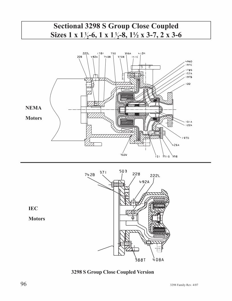
Sectional 3298 S Group Close Coupled
Sizes 1 x 1 12-6, 1 x 1 1
2-8, 1½ x 3-7, 2 x 3-6
96 3298 Family Rev. 4/07
3298 S Group Close Coupled Version
IEC
Motors
NEMA
Motors

3298 S Group Close Coupled
Sizes 1 x 1 12-6, 1 x 1 1
2-8, 1½ x 3-7, 2 x 3-6
3298 Family Rev. 4/07 97
3298 S Group Close Coupled
ItemNumber Part Name Material
100 Casing Ductile Iron / Tefzel®
101 Impeller, Assembly Carbon Filled Tefzel®
101A * Bearing SpiderStandard - Carbon filled Tefzel® / Silicon CarbideOptional - Carbon filled Tefzel / DryGuard Silicon
Carbide
122A Stationary ShaftStandard - Silicon Carbide
Optional - DryGuard Silicon Carbide141C Clamp Ring Ductile Iron157A Bearing Spacer - Radial Bearings Teflon®
178S * Key, Impeller to Radial Bearings Teflon®
178Y Key, Motor to Carrier Steel
197B * Bearing - RadialStandard - Carbon GraphiteOptional - Silicon Carbide
Optional - DryGuard Silicon Carbide197C * Bearing, Reverse Thrust Carbon Filled Teflon®
197D * Bearing, Impeller - ThrustCarbon Filled Teflon®
Optional - Silicon CarbideOptional - DryGuard Silicon Carbide
222L Set Screw Steel228 Motor Support - Close Coupled Cast Iron
351G * Gasket, Case Drain Gylon356A Hex Cap Screw - Clamp Ring to Case 304SS358 Flange - Case Drain Steel
360W * Gasket - Motor Support to Clamp Ring Aramid Fibers w/EPDM370B Hex Cap Screw - Motor Support to Clamp Ring 304SS
412M * O-Ring - Containment Shell
Standard - Viton®
Optional - EPDMOptional - Teflon® Encapsulated Viton®
Optional - Chemraz® 505Optional - Kalrez® 4079
426A Hex Cap Screw - Case Drain 304SS492A Access Hole Plug Steel740B Drive Magnet Assembly Cast Iron / Neohymium Iron750 Containment Shell Tefzel ®/ Fiber Reinforced Vinylester
* Recommended Spare Parts
ItemNumber Part Name Material
228 Frame, Close Coupled (IEC) Ductile Iron333L Screw, Set 304SS371 H.C. Screw - Motor to Frame Carbon Steel
388T H.C. Screw - Adapt to Frame 1 Carbon Steel408A Plug - Drain Carbon Steel492A Plug - Access Hole Carbon Steel503 Ring, Adapter 1 Cast Iron
742B Ring, Centering 2 Carbon Steel1 Used with Motor Frames 132 & 160 only.2 Used with Motor Frames 80 & 90 only.
6
Sectional 3298 M Group Frame Mounted
Sizes 3 x 4-7, 1½ x 3-8, 2 x 3-8, 1 x 2-10
98 3298 Family Rev. 4/07
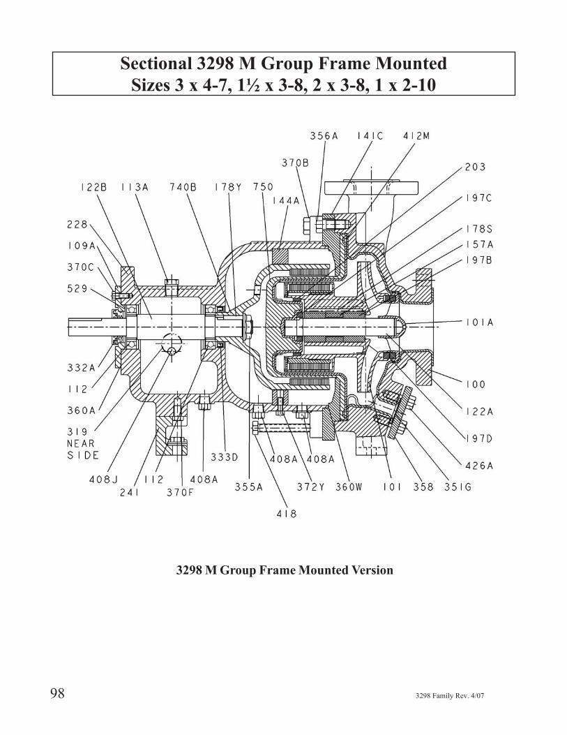
3298 M Group Frame Mounted Version

3298 M Group Frame Mounted
Sizes 3 x 4-7, 1½ x 3-8, 2 x 3-8, 1 x 2-10
3298 Family Rev. 4/07 99
Frame Mounted
Item Number Part Name Material100 Casing Ductile Iron / Tefzel®
101 Impeller, Assembly Carbon filled Tefzel®
101A* Bearing SpiderStandard - Carbon filled Tefzel® / Silicon Carbide
Optional - Carbon filled Tefzel® / DryGuard Silicon Car-bide
109A End Cover Ductile Iron112* Ball Bearings Steel113A Plug - Oil Fill Steel
122A Stationary ShaftStandard - Silicon Carbide
Optional - DryGuard Silicon Carbide122B Drive Shaft Steel141C Clamp Ring Ductile Iron144A Rub Ring Cast Iron157A Bearing Spacer - Radial Teflon®
178S* Key, Impeller to Bearings Teflon®
178Y Key, Drive Carrier Steel
197B* Bearing - radialStandard - Carbon GraphiteOptional - Silicon Carbide
Optional - DryGuard Silicon Carbide197C* Bearing, Reverse Thrust Carbon Filled Teflon®
197D* Bearing, Impeller - ThrustStandard - Carbon Filled Teflon®
Optional - Silicon CarbideOptional - DryGuard Silicon Carbide
203* Ring - Back Wearing Carbon Filled Teflon®
228 Frame - Bearing Cast Iron241 Frame Foot Cast Iron319 Sight Window Steel / Glass
332A Labyrinth Seal Carbon Filled Teflon®
333D* Lip Seal Buna Rubber351G* Gasket, Case Drain Gylon355A Flanged Hex Nut Steel356A Hex Cap Screw - Clamp Ring to Case 304SS358 Flange, Case Drain Steel
360A* Gasket - Cover to Frame Varnished Kraft360W* Gasket - Frame to Clamp Ring Aramid Fibers w/EPDM370B Hex Cap Screw - Frame to Clamp Ring 304SS370C Hex Cap Screw - Cover to Frame 304SS370F Hex Cap Screw - Frame Foot 304SS372Y Hex Cap Screw - Frame to Rub Ring 304SS408A Plug- Drain Steel408J Plug - Oiler Steel
412M* O-ring - Containment Shell
Standard - Viton®
Optional - EPDMOptional Teflon®
Optional - Chemraz® 505Optional - Kalrez® 4079
418 H. T. Bolt - Jacking 304SS426A Hex Cap Screw - Case Drain 304SS529* Washer, Wave Spring Steel740B Drive Carrier Cast Iron / Neodymiumn750 Containment Shell Tefzel® / Fiber Reinforced Vinylester
* Recommended Spare Parts
6
Sectional 3298 M Group Close Coupled
Sizes 3 x 4-7, 1½ x 3-8, 2 x 3-8, 1 x 2-10
100 3298 Family Rev. 4/07
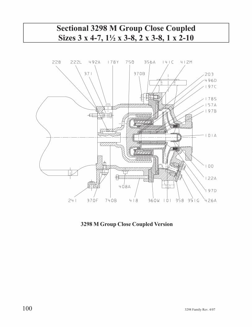
3298 M Group Close Coupled Version
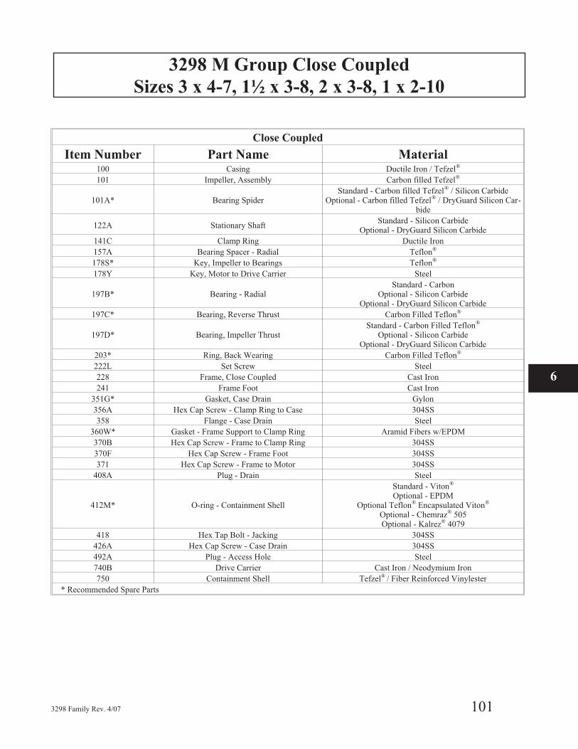
3298 M Group Close Coupled
Sizes 3 x 4-7, 1½ x 3-8, 2 x 3-8, 1 x 2-10
3298 Family Rev. 4/07 101
Close Coupled
Item Number Part Name Material100 Casing Ductile Iron / Tefzel®
101 Impeller, Assembly Carbon filled Tefzel®
101A* Bearing SpiderStandard - Carbon filled Tefzel® / Silicon Carbide
Optional - Carbon filled Tefzel® / DryGuard Silicon Car-bide
122A Stationary ShaftStandard - Silicon Carbide
Optional - DryGuard Silicon Carbide
141C Clamp Ring Ductile Iron
157A Bearing Spacer - Radial Teflon®
178S* Key, Impeller to Bearings Teflon®
178Y Key, Motor to Drive Carrier Steel
197B* Bearing - RadialStandard - Carbon
Optional - Silicon CarbideOptional - DryGuard Silicon Carbide
197C* Bearing, Reverse Thrust Carbon Filled Teflon®
197D* Bearing, Impeller ThrustStandard - Carbon Filled Teflon®
Optional - Silicon CarbideOptional - DryGuard Silicon Carbide
203* Ring, Back Wearing Carbon Filled Teflon®
222L Set Screw Steel
228 Frame, Close Coupled Cast Iron
241 Frame Foot Cast Iron
351G* Gasket, Case Drain Gylon
356A Hex Cap Screw - Clamp Ring to Case 304SS
358 Flange - Case Drain Steel
360W* Gasket - Frame Support to Clamp Ring Aramid Fibers w/EPDM
370B Hex Cap Screw - Frame to Clamp Ring 304SS
370F Hex Cap Screw - Frame Foot 304SS
371 Hex Cap Screw - Frame to Motor 304SS
408A Plug - Drain Steel
412M* O-ring - Containment Shell
Standard - Viton®
Optional - EPDMOptional Teflon® Encapsulated Viton®
Optional - Chemraz® 505Optional - Kalrez® 4079
418 Hex Tap Bolt - Jacking 304SS
426A Hex Cap Screw - Case Drain 304SS
492A Plug - Access Hole Steel
740B Drive Carrier Cast Iron / Neodymium Iron
750 Containment Shell Tefzel® / Fiber Reinforced Vinylester
* Recommended Spare Parts
6
3298 L Group Frame Mounted
Sizes 1½ x 3-10, 2 x 3-10, 3 x 4-10G, 3 x 4-10H, 4 x 6-10
102 3298 Family Rev. 4/07
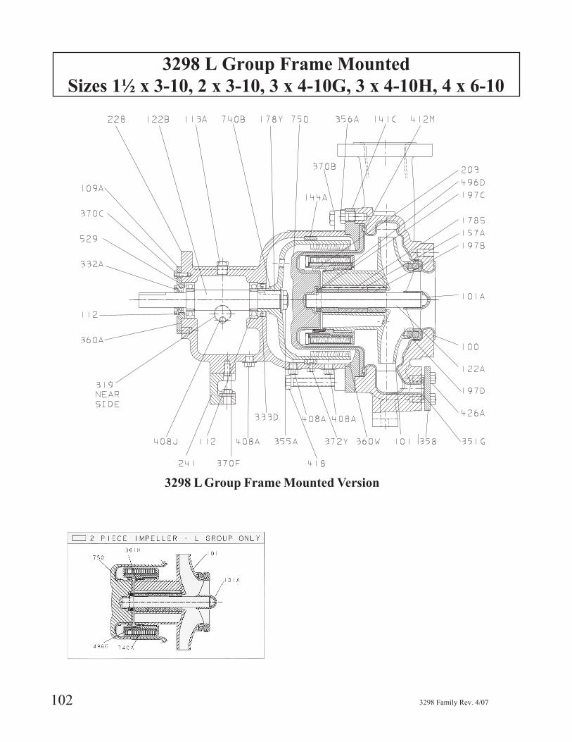
3298 L Group Frame Mounted Version

3298 L Group Frame Mounted
Sizes 1½ x 3-10, 2 x 3-10, 3 x 4-10G, 3 x 4-10H, 4 x 6-10
3298 Family Rev. 4/07 103
6
Frame Mounted
Item Number Part Name Material100 Casing Ductile Iron / Tefzel®
101 Impeller, Assembly Carbon Fiber Reinforced Tefzel®
101A* Bearing SpiderStandard - Carbon filled Tefzel® / Silicon Carbide
Optional - Carbon filled Tefzel® / DryGuard Silicon Car-bide
109A End Cover Ductile Iron112* Ball Bearings Steel113A Plug - Oil Fill Steel
122A Stationary ShaftStandard - Silicon Carbide
Optional -DryGuard Silicon Carbide122B Drive Shaft Steel141C Clamp Ring Ductile Iron144A Rub Ring Cast Iron157A Bearing Spacer - Radial Teflon®
178S* Key, Impeller to Bearings Teflon®
178Y Key, Drive Carrier Steel
197B* Bearing - radialStandard - Carbon GraphiteOptional - Silicon Carbide
Optional - DryGuard Silicon Carbide197C* Bearing, Reverse Thrust Carbon Filled Teflon®
197D* Bearing, Impeller - Thrust
Standard - Carbon Filled Teflon®
Optional - Silicon CarbideOptional - Carbon filled Tefzel® / DryGuard Silicon Car-
bide203* Ring - Back Wearing Carbon Filled Teflon®
228 Frame - Bearing Cast Iron241 Frame Foot Cast Iron319 Sight Window Steel / Glass
332A Labyrinth Seal Carbon Filled Teflon®
333D* Lip Seal Buna Rubber351G* Gasket, Case Drain Gylon355A Flanged Hex Nut Steel356A Hex Cap Screw - Clamp Ring to Case 304SS358 Flange, Case Drain Steel
360A* Gasket - Cover to Frame Varnished Kraft360W* Gasket - Frame to Clamp Ring Aramid Fibers w/EPDM361H Retaining Ring Teflon® Encapsulated Silicone370B Hex Cap Screw - Frame to Clamp Ring 304SS370C Hex Cap Screw - Cover to Frame 304SS370F Hex Cap Screw - Frame Foot 304SS372Y Hex Cap Screw - Frame to Rub Ring 304SS408A Plug- Drain Steel408J Plug - Oiler Steel
412M* O-Ring - Containment Shell
Standard - Viton®
Optional - EPDMOptional Teflon®
Optional - Chemraz® 505Optional - Kalrez® 4079
418 H. T. Bolt - Jacking 304SS426A Hex Cap Screw - Case Drain 304SS
496G* O-ring Driven Magnet Assembly
Standard Viton®
Optional - EPDMOptional - Teflon®
Optional - Chemraz® 505Optional - Kalrez® 4079
529* Washer, Wave Spring Steel740A Driven Magnet Assembly Tefzel® / Neodymium Iron740B Drive Carrier Cast Iron / Neodymiumn750 Containment Shell Carbon filled Tefzel® / Fiber Reinforced Vinylester
3298 L Group Close Coupled
Sizes 1½ x 3-10, 2 x 3-10, 3 x 4-10G, 3 x 4-10H, 4 x 6-10
104 3298 Family Rev. 4/07
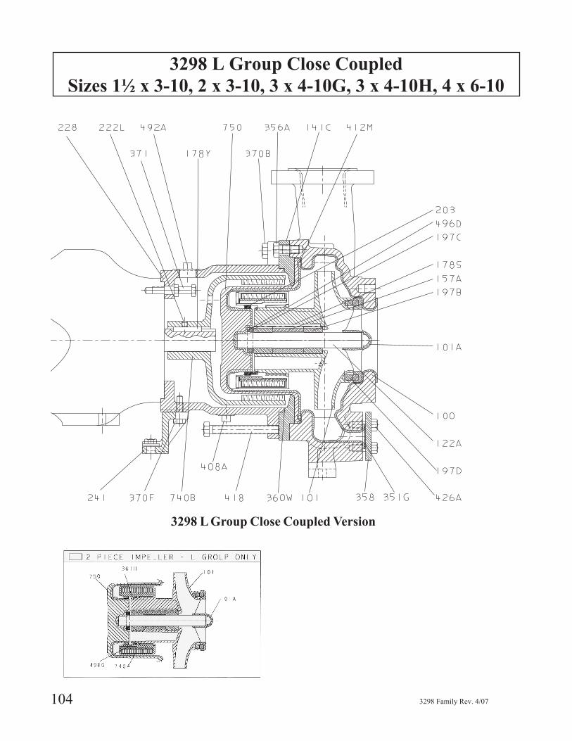
3298 L Group Close Coupled Version

3298 L Group Close Coupled
Sizes 1½ x 3-10, 2 x 3-10, 3 x 4-10G, 3 x 4-10H, 4 x 6-10
3298 Family Rev. 4/07 105
Close Coupled
Item Number Part Name Material100 Casing Ductile Iron / Tefzel®
101 Impeller, Assembly Carbon Fiber Tefzel®
101A* Bearing SpiderStandard - Carbon filled Tefzel® / Silicon Carbide
Optional - Carbon filled Tefzel® / DryGuard Silicon Car-bide
122A Stationary ShaftStandard - Silicon Carbide
Optional - DryGuard Silicon Carbide
141C Clamp Ring Ductile Iron
157A Bearing Spacer - Radial Teflon®
178S* Key, Impeller to Bearings Teflon®
178Y Key, Motor to Drive Carrier Steel
197B* Bearing - RadialStandard - Carbon
Optional - Silicon CarbideOptional - DryGuard Silicon Carbide
197C* Bearing, Reverse Thrust Carbon Filled Teflon®
197D* Bearing, Impeller ThrustStandard - Carbon Filled Teflon®
Optional - Silicon CarbideOptional - DryGuard Silicon Carbide
203* Ring, Back Wearing Carbon Filled Teflon®
222L Set Screw Steel
228 Frame, Close Coupled Cast Iron
241 Frame Foot Cast Iron
351G* Gasket, Case Drain Gylon
356A Hex Cap Screw - Clamp Ring to Case 304SS
358 Flange - Case Drain Steel
360W* Gasket - Frame Support to Clamp Ring Aramid Fibers w/EPDM
361H Retaining Ring Teflon® Encapsulated Silicone
370B Hex Cap Screw - Frame to Clamp Ring 304SS
370F Hex Cap Screw - Frame Foot 304SS
371 Hex Cap Screw - Frame to Motor 304SS
408A Plug - Drain Steel
412M* O-Ring - Containment Shell
Standard - Viton®
Optional - EPDMOptional Teflon® Encapsulated Viton®
Optional - Chemraz® 505Optional - Kalrez® 4079
418 Hex Tap Bolt - Jacking 304SS
426A Hex Cap Screw - Case Drain 304SS
492A Plug - Access Hole Steel
740A Driven Magnet Assembly Tefzel® Neodymium Iron
740B Drive Carrier Cast Iron / Neodymium Iron
750 Containment Shell Carbon filled Tefzel® / Fiber Reinforced Vinylester
496G* O-Ring - Driven Magnet Assembly
Standard Viton®
Optional - EPDMOptional Teflon® Encapsulated Viton®
Optional - Chemraz® 505Optional - Kalrez® 4079
* Recommended Spare Parts
6

SP 3298 S Group Frame Mounted
Sizes 1 x 112-6, 2 x 3-6
106 3298 Family Rev. 4/07
SP 3298 S Group Frame Mounted Version
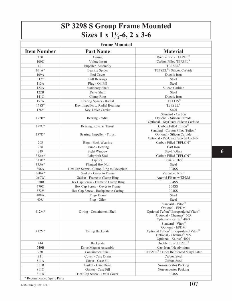
SP 3298 S Group Frame Mounted
Sizes 1 x 112-6, 2 x 3-6
3298 Family Rev. 4/07 107
Frame Mounted
Item Number Part Name Material100 Casing Ductile Iron / TEFZEL®
100U Volute Insert Carbon Filled TEFZEL®
101 Impeller, Assembly TEFZEL®
101A* Bearing Spider TEFZEL® / Silicon Carbide
109A End Cover Ductile Iron
112* Ball Bearings Steel
113A Plug - Oil Fill Steel
122A Stationary Shaft Silicon Carbide
122B Drive Shaft Steel
141C Clamp Ring Ductile Iron
157A Bearing Spacer - Radial TEFLON®
178S* Key, Impeller to Radial Bearings TEFZEL®
178Y Key, Drive Carrier Steel
197B* Bearing - radialStandard - Carbon
Optional - Silicon CarbideOptional - DryGuard Silicon Carbide
197C* Bearing, Reverse Thrust Carbon Filled Teflon®
197D* Bearing, Impeller - ThrustStandard - Carbon Filled Teflon®
Optional - Silicon CarbideOptional - DryGuard Silicon Carbide
203 Ring - Back Wearing Carbon Filled TEFLON®
228 Frame - Bearing Cast Iron
319 Sight Window Steel / Glass
332A* Labyrinth Seal Carbon Filled TEFLON®
333D* Lip Seal Buna Rubber
355A* Flanged Hex Nut Steel
356A Hex Cap Screw - Clamp Ring to Backplate 304SS
360A* Gasket - Cover to Frame Varnished Kraft
360W Gasket - Frame to Clamp Ring Aramid Fibers w/EPDM
370B Hex Cap Screw - Frame to Clamp Ring 304SS
370C Hex Cap Screw - Cover to Frame 304SS
372V Hex Cap Screw - Backplate to Casing 304SS
408A Plug- Drain Steel
408J Plug - Oiler Steel
412M* O-ring - Containment Shell
Standard - Viton®
Optional - EPDMOptional Teflon® Encapsulated Viton®
Optional - Chemraz® 505Optional - Kalrez® 4079
412V* O-ring Backplate
Standard - Viton®
Optional - EPDMOptional Teflon® Encapsulated Viton®
Optional - Chemraz® 505Optional - Kalrez® 4079
444 Backplate Ductile Iron/TEFZEL®
740B Drive Magnet Assembly Cast Iron / Neodymium
750 Containment Shell TEFZEL® / Fiber Reinforced Vinyl Ester
811 Cover - Case Drain Carbon Steel
811A Cover - Case Fill Carbon Steel
811B Gasket - Case Drain Non-Asbestos Packing
811C Gasket - Case Fill Non-Asbestos Packing
811D Hex Cap Screw - Drain Cover 304SS
* Recommended Spare Parts
6

SP 3298 S Group Close Coupled
Sizes 1 x 1 12-6, 2 x 3-6
108 3298 Family Rev. 4/07
IEC
Motors
SP 3298 S Group Close Coupled Version
NEMA
Motors
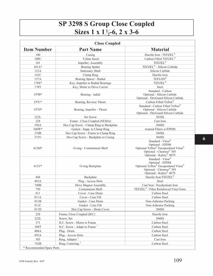
SP 3298 S Group Close Coupled
Sizes 1 x 1 12-6, 2 x 3-6
3298 Family Rev. 4/07 109
Close Coupled
Item Number Part Name Material100 Casing Ductile Iron / TEFZEL®
100U Volute Insert Carbon Filled TEFZEL®
101 Impeller, Assembly TEFZEL®
101A* Bearing Spider TEFZEL® - Silicon Carbide
122A Stationary Shaft Silicon Carbide
141C Clamp Ring Ductile Iron
157A Bearing Spacer - Radial TEFLON®
178S* Key, Impeller to Radial Bearings TEFZEL®
178Y Key, Motor to Drive Carrier Steel
197B* Bearing - radialStandard - Carbon
Optional - Silicon CarbideOptional - DryGuard Silicon Carbide
197C* Bearing, Reverse Thrust Carbon Filled Teflon®
197D* Bearing, Impeller - ThrustStandard - Carbon Filled Teflon®
Optional - Silicon CarbideOptional - DryGuard Silicon Carbide
222L Set Screw 303SS
228 Frame - Close Coupled (NEMA) Cast Iron
356A Hex Cap Screw - Clamp Ring to Backplate 304SS
360W* Gasket - Supp. to Clamp Ring Aramid Fibers w/EPDM
370B Hex Cap Screw - Frame to Clamp Ring 304SS
372V Hex Cap Screw - Backplate to Casing 304SS
412M* O-ring - Containment Shell
Standard - Viton®
Optional - EPDMOptional Teflon® Encapsulated Viton®
Optional - Chemraz® 505Optional - Kalrez® 4079
412V* O-ring Backplate
Standard - Viton®
Optional - EPDMOptional Teflon® Encapsulated Viton®
Optional - Chemraz® 505Optional - Kalrez® 4079
444 Backplate Ductile Iron/TEFZEL®
492A Plug - Access Hole Steel
740B Drive Magnet Assembly Cast Iron / Neodymium Iron
750 Containment Shell TEFZEL® / Fiber Reinforced Vinyl Ester
811 Cover - Case Drain Carbon Steel
811A Cover - Case Fill Carbon Steel
811B Gasket - Case Drain Non-Asbestos Packing
811C Gasket - Case Fill Non-Asbestos Packing
811D Hex Cap Screw - Drain Cover 304SS
228 Frame, Close Coupled (IEC) Ductile Iron
222L Screw, Set 304SS
371 H.C. Screw - Motor to Frame Carbon Steel
388T H.C. Screw - Adapt to Frame 1 Carbon Steel
408A Plug - Drain Carbon Steel
492A Plug - Access Hole Carbon Steel
503 Ring, Adapter 1 Cast Iron
742B Ring, Centering 2 Carbon Steel
* Recommended Spare Parts
6
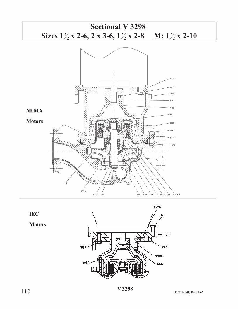
Sectional V 3298
Sizes 1 12 x 2-6, 2 x 3-6, 1 1
2 x 2-8 M: 1 12 x 2-10
110 3298 Family Rev. 4/07
IEC
Motors
V 3298
NEMA
Motors

V 3298 Group Close Coupled
Sizes S: 1 12 x 2-6, 2 x 3-6, 1 1
2 x 2-8 M: 1 12 x 2-10
3298 Family Rev. 4/07 111
Close Coupled
Item Number Part Name Material100 Casing Ductile Iron / TEFZEL®
101 Impeller, Assembly TEFZEL®
101A Bearing Spider TEFZEL® - Silicon Carbide
122A Stationary Shaft Silicon Carbide
141C Clamp Ring Ductile Iron
157A Bearing Spacer - Radial TEFLON®
178S Key, Impeller to Radial Bearings TEFZEL®
178Y Key, Motor to Magnet Assembly Steel
197B Bearing - RadialStandard - Carbon
Optional - Silicon CarbideOptional - DryGuard Silicon Carbide
197C Bearing, Reverse Thrust Carbon Filled Teflon®
197D Bearing, Impeller - ThrustStandard - Carbon Filled Teflon®
Optional - Silicon CarbideOptional - DryGuard Silicon Carbide
203 Ring - Back Wear Ring Carbon Filled Teflon
222L Set Screw 303SS
228 Frame - Close Coupled (NEMA) Cast Iron
351G Gasket, Casing Drain Non-Asbestos Packing
356A Hex Cap Screw - Clamp Ring to Case 304SS
358 Cover, Drain Steel
360W Gasket - Supp. To Clamp Ring Aramid Fibers w/ EDPM
370B Hex Cap Screw - Backplate to Casing 304SS
412M O-ring - Containment Shell
Standard - Viton®
Optional - EPDMOptional Teflon® Encapsulated Viton®
Optional - Chemraz® 505Optional - Kalrez® 4079
426A Hex Cap Screw - Drain Cover 304SS
492A Plug - Access Hole Steel
740B Magnet Assemby Cast Iron / Neodymium Iron
750 Containment Shell TEFZEL® / Fiber Reinforced Vinyl Ester
ItemNumber Part Name Material
228 Frame, Close Coupled (IEC) Ductile Iron
222L Screw, Set 304SS
371 H.C. Screw - Motor to Frame Carbon Steel
388T H.C. Screw - Adapt to Frame 1 Carbon Steel
408A Plug - Drain Carbon Steel
492A Plug - Access Hole Carbon Steel
503 Ring, Adapter 1 Cast Iron
742B Ring, Centering 2 Carbon Steel1 Used with Motor Frames 132 & 160 only.2 Used with Motor Frames 80 & 90 only.* Recommended Spare Parts
6

112 3298 Family Rev. 4/07
SPARE AND REPAIR PARTSRECOMMENDED SPARES . . . . . . . . . . . . . . . . . . . . . . . . . . . 113
HOW TO ORDER PARTS . . . . . . . . . . . . . . . . . . . . . . . . . . . . 115
INTERCHANGEABILITY . . . . . . . . . . . . . . . . . . . . . . . . . 117-122
RETURN OF MATERIALS . . . . . . . . . . . . . . . . . . . . . . . . . . . 123
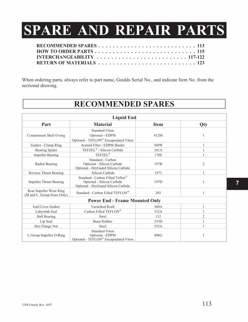
When ordering parts, always refer to part name, Goulds Serial No., and indicate Item No. from the
sectional drawing.
RECOMMENDED SPARES
3298 Family Rev. 4/07 113
Liquid End
Part Material Item Qty
Containment Shell O-ring
Standard-Viton
412M 1Optional - EDPM
Optional - TEFLON® Encapsulated Viton
Gasket - Clamp Ring Aramid Fiber / EDPM Binder 360W 1
Bearing Spider TEFZEL® / Silicon Carbide 101A 1
Impeller Bearing TEFZEL® 178S 1
Radial BearingStandard - Carbon
Optional - Silicon CarbideOptional - DryGuard Silicon Carbide
197B 2
Reverse Thrust Bearing Silicon Carbide 1973 1
Impeller Thrust BearingStandard - Carbon Filled Teflon®
Optional - Silicon CarbideOptional - DryGuard Silicon Carbide
197D 1
Rear Impeller Wear Ring(M and L Group Sizes Only)
Standard - Carbon Filled TEFLON® 203 1
Power End - Frame Mounted Only
End Cover Gasket Varnished Kraft 360A 1
Labyrinth Seal Carbon Filled TEFLON® 332A 1
Ball Bearing Steel 112 2
Lip Seal Buna Rubber 333D 1
Hex Flange Nut Steel 355A 1
L Group Impeller O-RingStandard-Viton
Optional - EDPMOptional - TEFLON® Encapsulated Viton
496G 1
7

114 3298 Family Rev. 4/07
Table 12
3298 Repair Kits
Size
Bearing Kits1 Repair Kit2
CarbonSilicon
CarbideDry-
Guard™
Carbon /Silicon
Carbide
Dry-
Guard™
PowerEndKit3
XS Group N/A
1X1.5-5 R298BKCXS26 R298BKSXS15 R298BKSFXS15 R298K155V R298RKSFX15
1.5X2-6 R298BKCXS6 R298BKSXS6 R298BKSFXS6 R298RK526V R298RKS526 N/A
S Group R298PKS
1X1.5-6 R298BKCS15 R298BKSS15 R298BKSF15 R298RK156V R298RKSF15
1X1.5-8 R298BKCS15 R298BKSS15 R298BKSF15 R298RK158V R298RKSF15
1.5X3-7 R298BKCS3 R298BKSS3 R298BKSF3 R298RK36V R298RKSF3
2X3-6 R298BKCS3 R298BKSS3 R298BKSF3 R298RK36V R298RKSF3
M Group R298PKML
1.5X3-8 R298BKCM153 R298BKSM153 R298BKSFM153 R298RK538V R298RKSF538
1X2-10 R298BKCM2 R298BKSM2 R298BKSFM3 R298RK210V R298RKSFM2
2X3-8 R298BKCM3 R298BKSM3 R3+9BKSFM3 R298RK38V R298RKSFM3
3X4-7 R298BKCM4 R298BKSM4 R298BKSFM4 R298RK47V R298RKSFM4
L Group R298PKML
1.5X3-10 R298BKCL310 R298BKSL310 R298BKSFL310 R298RK5310V R298RKSF5310
2X3-10 R298BKCL310 R298BKSL310 R298BKSFL310 R298RK2310V R298RKSF2310
3X4-10H R298BKCL4 R298BKSL4 R298BKSFL4 R298RK410V R298RKSFL4
3X4-10G R298BKCL410 R298BKS4310 R298BKSFL410 R298RK3410V R298RKSF3410
4X6-10 R298BKCL6 R298BKSL6 R298BKSFL6 R298RK610V R298RKSFL6
1 The Bearing Kits include the spider, the thrust bearing, the bearing spacer, bearing key, radial bearings, rear
impeller wear ring (if required), and the containment shell o-ring.
2 The Pump Repair Kits include the impeller, shaft, reverse thrust bearing and the containment shell
(L groups also include magnet retaining ring.)
3 The Power End Repair Kits include the ball bearings, drive carrier key, lip seal, hex flange nut (drive carrier shaft
nut), bearing end cover gasket, frame gasket, and the labyrinth o-rings.

3298 Family Rev. 4/07 115
7

INTERCHANGEABILITY 3298 XS GROUP
116 3298 Family Rev. 4/07

INTERCHANGEABILITY 3298 S GROUP
3298 Family Rev. 4/07 117
7

INTERCHANGEABILITY 3298 M GROUP
INTERCHANGEABILITY 3298 M GROUP (SIZE 1½ x 3-8 ONLY)
118 3298 Family Rev. 4/07
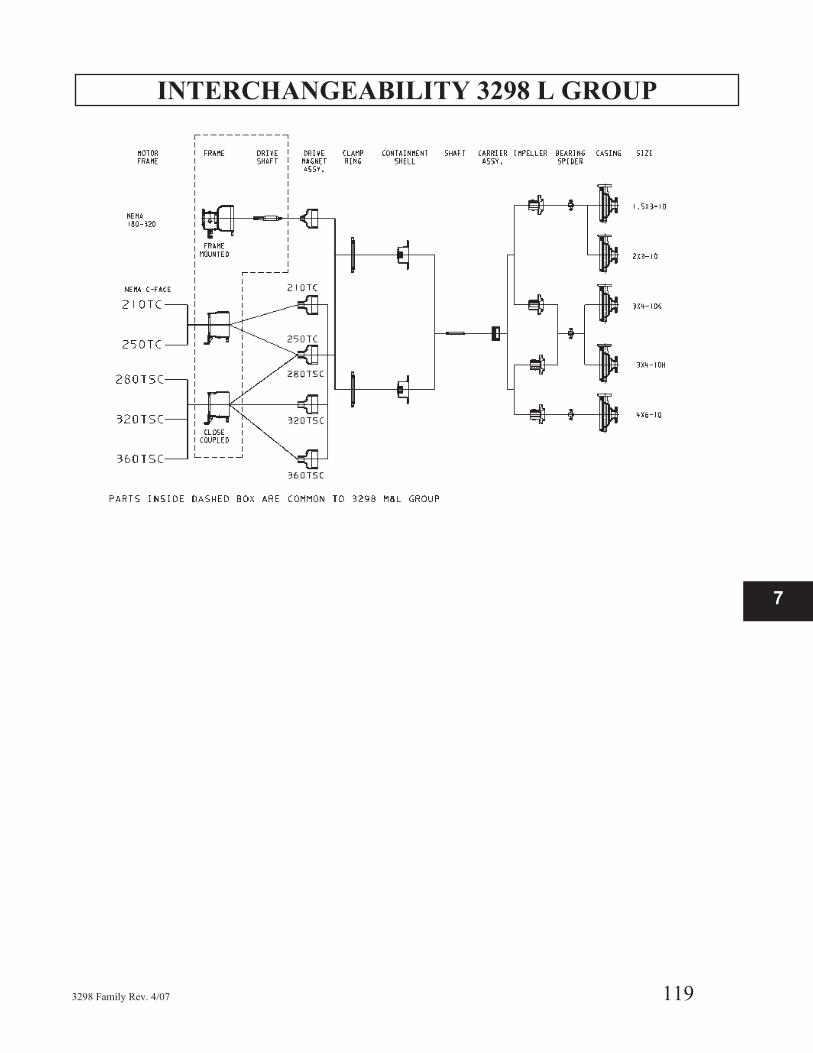
INTERCHANGEABILITY 3298 L GROUP
3298 Family Rev. 4/07 119
7

INTERCHANGEABILITY SP 3298 S GROUP
120 3298 Family Rev. 4/07

INTERCHANGEABILITY V 3298 S GROUP
3298 Family Rev. 4/07 121
7
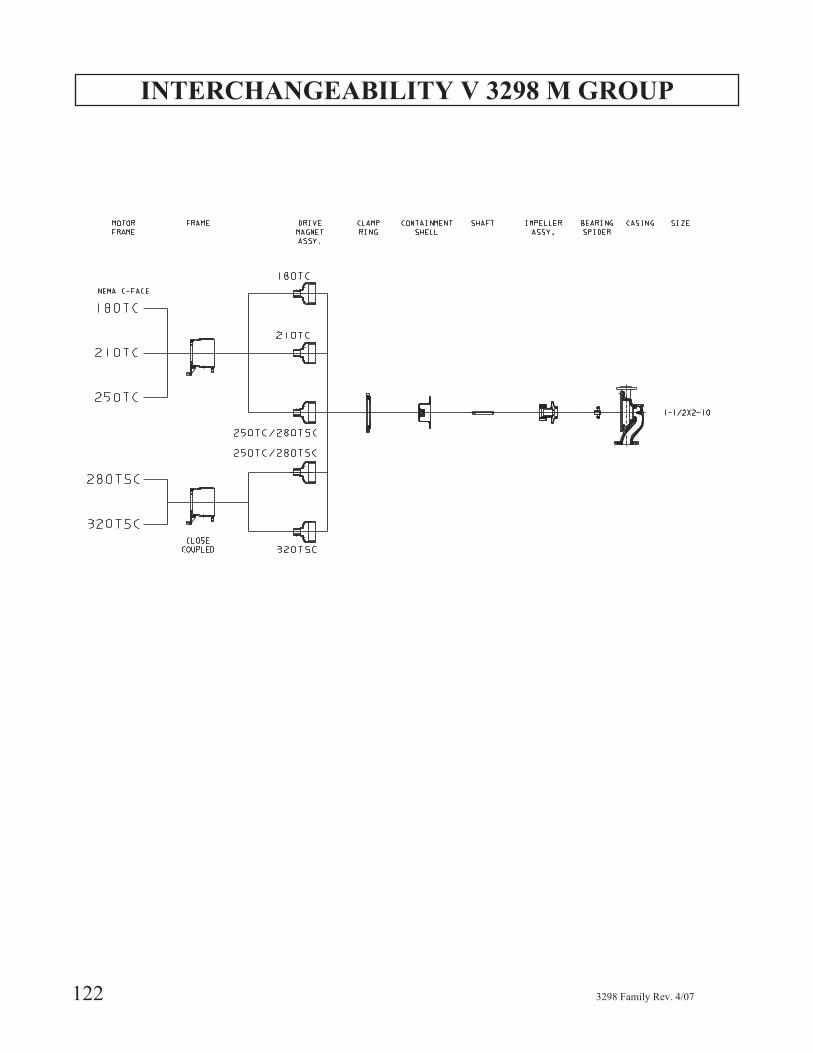
INTERCHANGEABILITY V 3298 M GROUP
122 3298 Family Rev. 4/07
RETURN OF MATERIALS
If it is necessary to return the pump to a Goulds factory orrepair facility for service, certain procedures must befollowed.
Do not return any parts without authorization from thewarranty engineer, a warranty claim number, and thepreprinted shipping label supplied by Goulds. In rareinstances because of the pumpage, ITT Goulds PumpsWarranty Services may, at their option, decide not to havethe parts returned.
The parts being returned must be decontaminated prior toshipment. The decontamination must be verified inwriting. The correct Material Safety Data Sheet (MSDS)must accompany the parts along with decontamination"sign off." This information is stated within the ITT
Goulds Pumps "decontamination procedure." TheWarranty Service engineer will send a copy of thisprocedure to the customer. Please remember thatinspection of the parts cannot be started until we receivethe proper documentation. This is a safety and legal issueand consequently strict adherence to procedure ismandatory — there will be no exceptions.
Before shipping, check with your carrier for specialprocedures that may be required when shipping highlymagnetic materials.
All pumps must be decontaminated prior to return. Referto Preparation for Disassembly and DecontaminationProcedure.
3298 Family Rev. 4/07 123
7

124 3298 Family Rev. 4/07
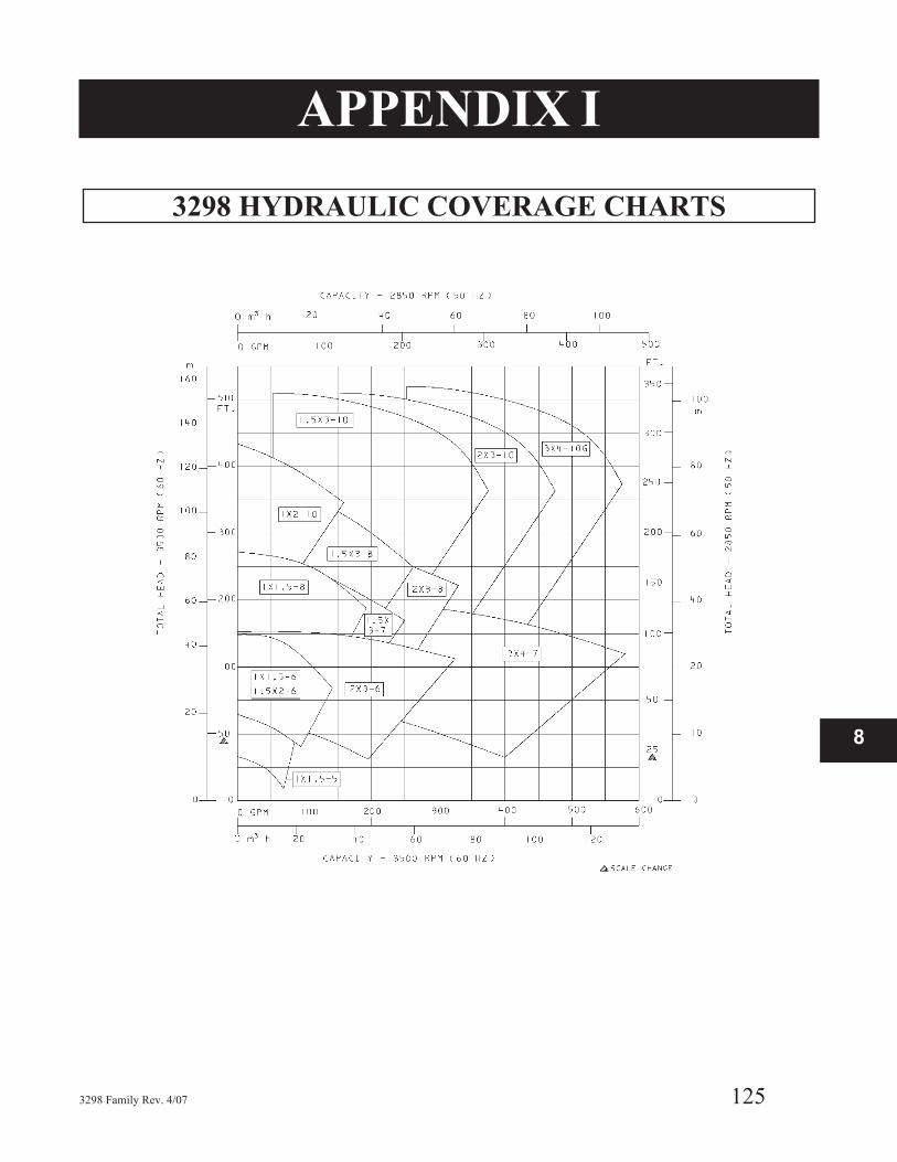
APPENDIX I
3298 HYDRAULIC COVERAGE CHARTS
3298 Family Rev. 4/07 125
8

3298 HYDRAULIC COVERAGE CHARTS
126 3298 Family Rev. 4/07
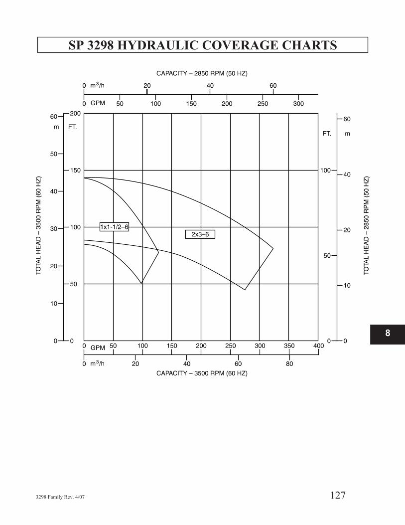
SP 3298 HYDRAULIC COVERAGE CHARTS
3298 Family Rev. 4/07 127
8
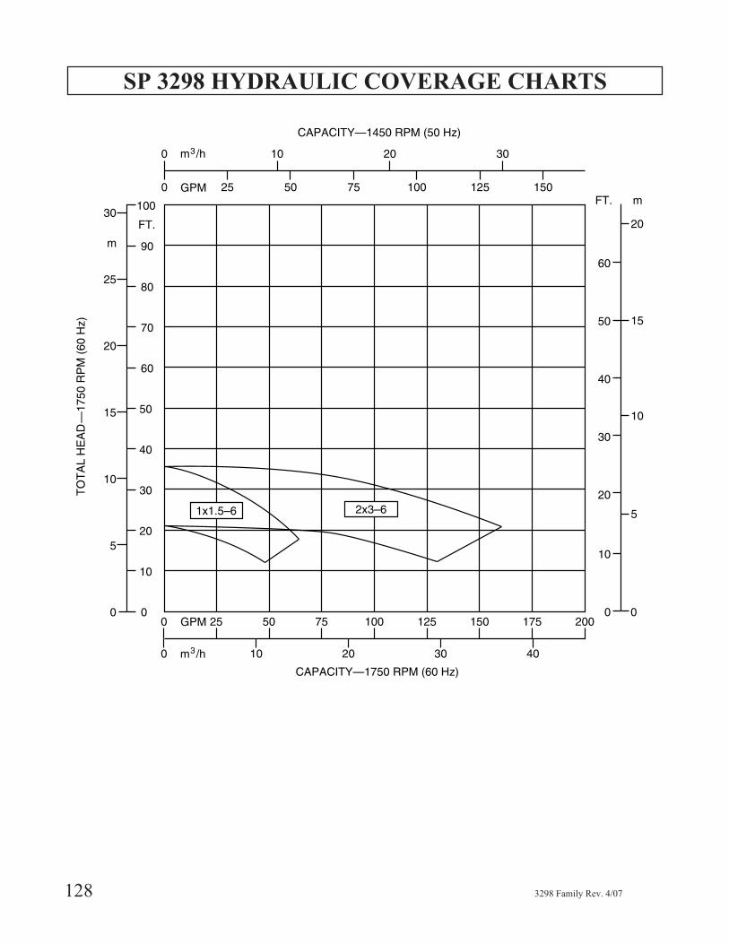
SP 3298 HYDRAULIC COVERAGE CHARTS
128 3298 Family Rev. 4/07

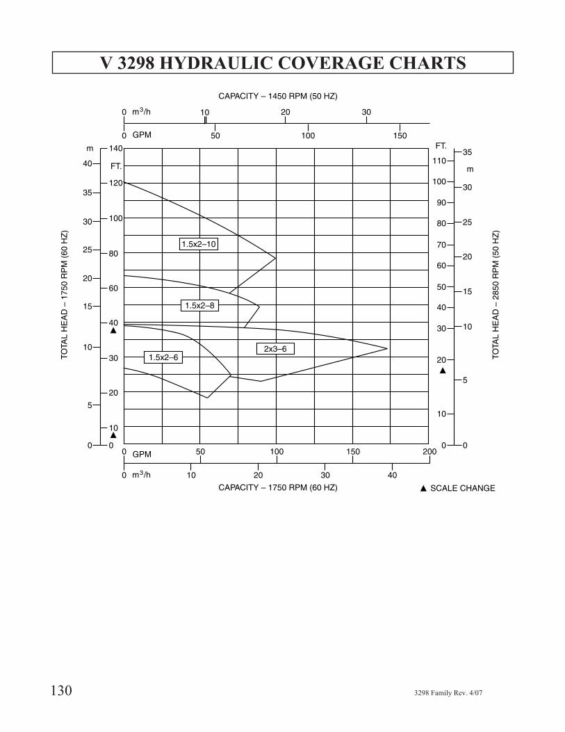
V 3298 HYDRAULIC COVERAGE CHARTS
3298 Family Rev. 4/07 129
8
V 3298 HYDRAULIC COVERAGE CHARTS
130 3298 Family Rev. 4/07
APPENDIX II
COUPLING GUARD INSTALLATION -
Frame Mounted Only
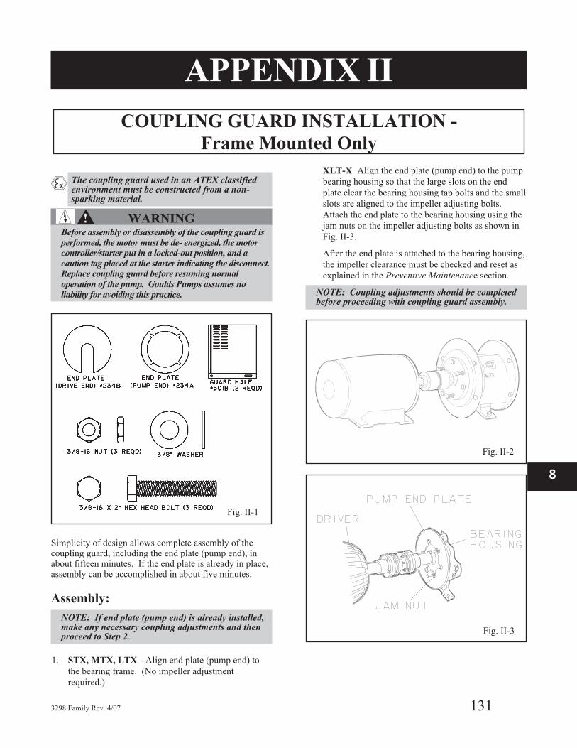
� The coupling guard used in an ATEX classifiedenvironment must be constructed from a non-sparking material.
�! WARNINGBefore assembly or disassembly of the coupling guard isperformed, the motor must be de- energized, the motorcontroller/starter put in a locked-out position, and acaution tag placed at the starter indicating the disconnect.Replace coupling guard before resuming normaloperation of the pump. Goulds Pumps assumes noliability for avoiding this practice.
Simplicity of design allows complete assembly of thecoupling guard, including the end plate (pump end), inabout fifteen minutes. If the end plate is already in place,assembly can be accomplished in about five minutes.
Assembly:
NOTE: If end plate (pump end) is already installed,make any necessary coupling adjustments and thenproceed to Step 2.
1. STX, MTX, LTX - Align end plate (pump end) to
the bearing frame. (No impeller adjustment
required.)
XLT-X Align the end plate (pump end) to the pump
bearing housing so that the large slots on the end
plate clear the bearing housing tap bolts and the small
slots are aligned to the impeller adjusting bolts.
Attach the end plate to the bearing housing using the
jam nuts on the impeller adjusting bolts as shown in
Fig. II-3.
After the end plate is attached to the bearing housing,
the impeller clearance must be checked and reset as
explained in the Preventive Maintenance section.
NOTE: Coupling adjustments should be completedbefore proceeding with coupling guard assembly.
3298 Family Rev. 4/07 131
8
Fig. II-1
Fig. II-2
Fig. II-3
B

2. Spread bottom of coupling guard half (pump end)
slightly and place over pump end plate as shown in
Fig. II-4. The annular groove in the guard half is
located around the end plate (Fig. II-5).
3. After the coupling guard half (pump end) is located
around the end plate, secure it with a bolt, nut and
two washers through the round hole at the front end
of the guard half as shown in Fig. II-6. Tighten
securely (Fig. II-7).
4. Spread bottom of coupling guard half (driver end)
slightly and place over coupling guard half (pump
end) so that annular groove in coupling guard half
(driver end) faces the motor as shown in Fig. II-8.
132 3298 Family Rev. 4/07
Fig. II-4
Fig. II-5
Fig. II-6
Fig. II-7
Fig. II-8
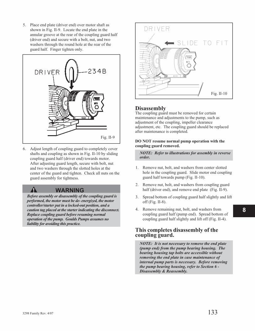
5. Place end plate (driver end) over motor shaft as
shown in Fig. II-9. Locate the end plate in the
annular groove at the rear of the coupling guard half
(driver end) and secure with a bolt, nut, and two
washers through the round hole at the rear of the
guard half. Finger tighten only.
6. Adjust length of coupling guard to completely cover
shafts and coupling as shown in Fig. II-10 by sliding
coupling guard half (driver end) towards motor.
After adjusting guard length, secure with bolt, nut
and two washers through the slotted holes at the
center of the guard and tighten. Check all nuts on the
guard assembly for tightness.
▲! WARNINGBefore assembly or disassembly of the coupling guard isperformed, the motor must be de- energized, the motorcontroller/starter put in a locked-out position, and acaution tag placed at the starter indicating the disconnect.Replace coupling guard before resuming normaloperation of the pump. Goulds Pumps assumes noliability for avoiding this practice.
DisassemblyThe coupling guard must be removed for certainmaintenance and adjustments to the pump, such asadjustment of the coupling, impeller clearanceadjustment, etc. The coupling guard should be replacedafter maintenance is completed.
DO NOT resume normal pump operation with the
coupling guard removed.
NOTE: Refer to illustrations for assembly in reverseorder.
1. Remove nut, bolt, and washers from center slotted
hole in the coupling guard. Slide motor end coupling
guard half towards pump (Fig. II-10).
2. Remove nut, bolt, and washers from coupling guard
half (driver end), and remove end plate (Fig. II-9).
3. Spread bottom of coupling guard half slightly and lift
off (Fig. II-8).
4. Remove remaining nut, bolt, and washers from
coupling guard half (pump end). Spread bottom of
coupling guard half slightly and lift off (Fig. II-4).
This completes disassembly of thecoupling guard.
NOTE: It is not necessary to remove the end plate(pump end) from the pump bearing housing. Thebearing housing tap bolts are accessible withoutremoving the end plate in case maintenance ofinternal pump parts is necessary. Before removingthe pump bearing housing, refer to Section 6 -Disassembly & Reassembly.
3298 Family Rev. 4/07 133
8
Fig. II-9
Fig. II-10

134 3298 Family Rev. 4/07
APPENDIX IIIIMPELLER AND SP 3298 TRIM PROCEDURE
IMPELLER TRIM PROCEDURE
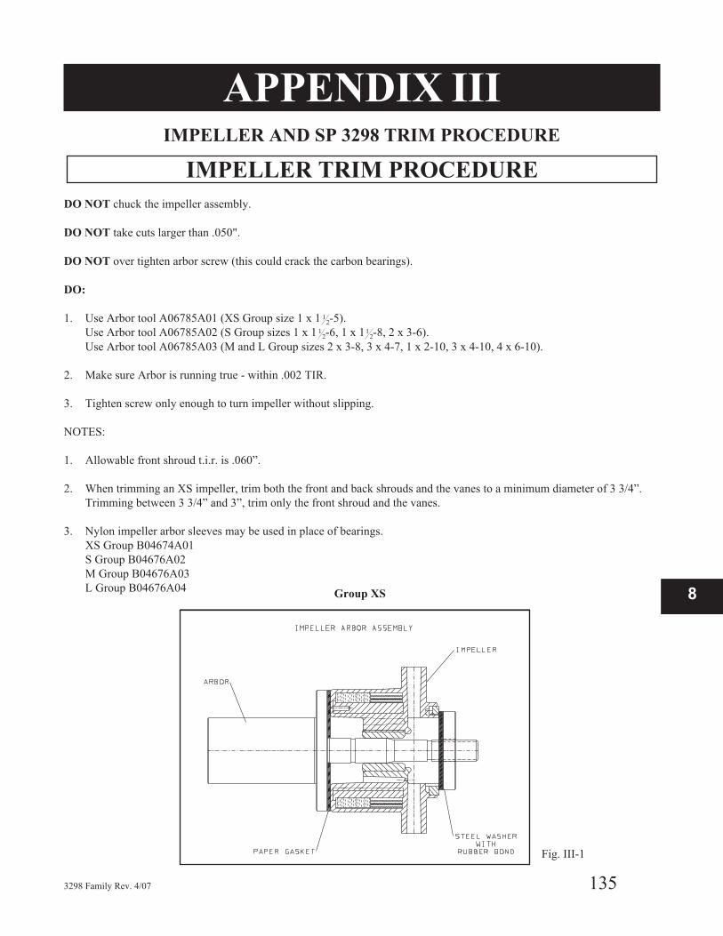
DO NOT chuck the impeller assembly.
DO NOT take cuts larger than .050".
DO NOT over tighten arbor screw (this could crack the carbon bearings).
DO:
1. Use Arbor tool A06785A01 (XS Group size 1 x 1 12-5).
Use Arbor tool A06785A02 (S Group sizes 1 x 1 12-6, 1 x 11
2-8, 2 x 3-6).
Use Arbor tool A06785A03 (M and L Group sizes 2 x 3-8, 3 x 4-7, 1 x 2-10, 3 x 4-10, 4 x 6-10).
2. Make sure Arbor is running true - within .002 TIR.
3. Tighten screw only enough to turn impeller without slipping.
NOTES:
1. Allowable front shroud t.i.r. is .060”.
2. When trimming an XS impeller, trim both the front and back shrouds and the vanes to a minimum diameter of 3 3/4”.
Trimming between 3 3/4” and 3”, trim only the front shroud and the vanes.
3. Nylon impeller arbor sleeves may be used in place of bearings.
XS Group B04674A01
S Group B04676A02
M Group B04676A03
L Group B04676A04
3298 Family Rev. 4/07 135
8Group XS
Fig. III-1
IMPELLER TRIM PROCEDURE
136 3298 Family Rev. 4/07
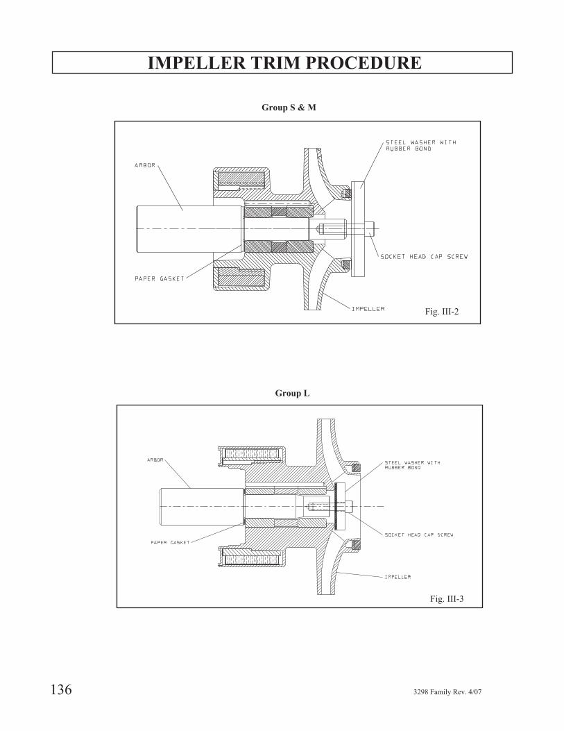
Fig. III-2
Group S & M
Fig. III-3
Group L

RECOMMENDED CUTTING TOOL
SP3298 VOLUTE INSERT TRIM PROCEDURE
DO NOT take cuts larger than .050”
DO:
1. Use Arbor Tool C06820A (SP3298 1X1.5-6)
2.. Use Arbor Tool C06821A (SP3298 2X3-6)
3. Make sure arbor is running true within .002” tir.
3298 Family Rev. 4/07 137
8
Fig. III-5
Fig. III-4

SP3298 VOLUTE INSERT
CUTWATER TRIM PROCEDURE
Machine cutwater diameter to full depth "R" as shown inTable III-1.
a. Use arbor C06820A for SP3298 1x1.5-6b. Use arbor C06821A for SP3298 2x3-6
Table III-1Impeller Diameter "R" +/0 0/010"
5.00 2.563
5.12 2.625
5.25 2.688
5.38 2.750
5.50 2.813
5.62 2.875
5.75 2.938
5.88 3.000
6.00 3.063
6.06 3.094
138 3298 Family Rev. 4/07
III-6
III-7
APPENDIX IV
POWER MONITORS
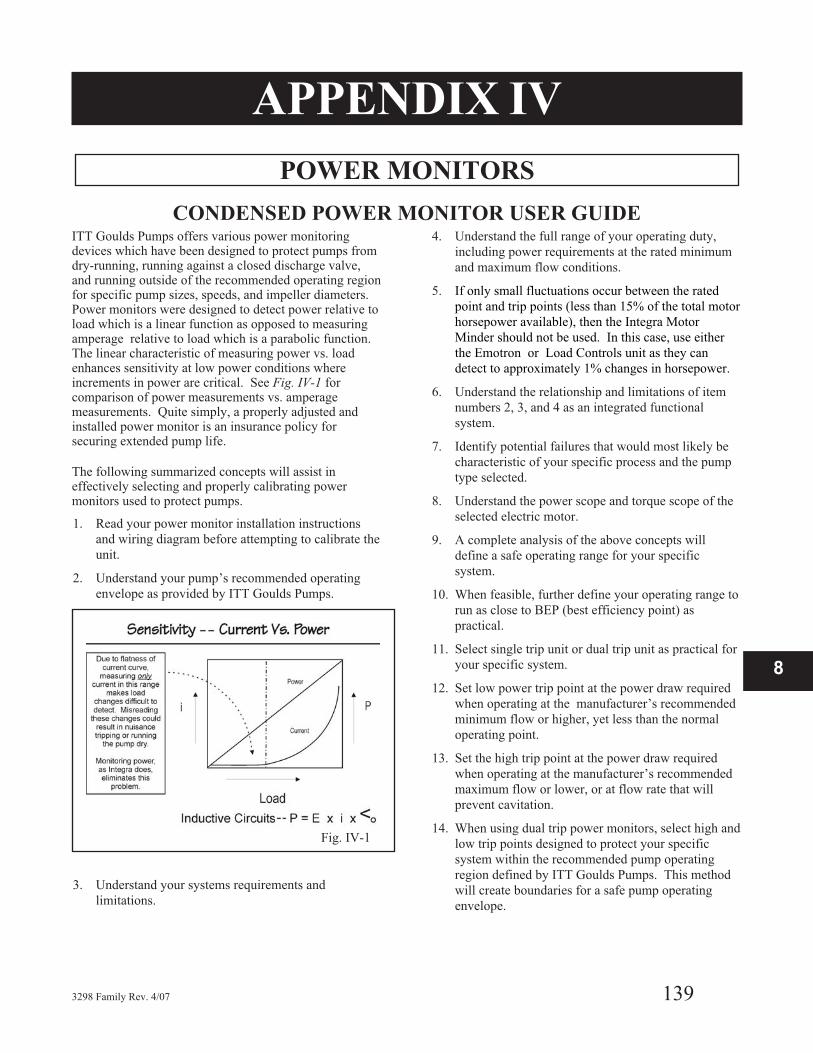
CONDENSED POWER MONITOR USER GUIDEITT Goulds Pumps offers various power monitoringdevices which have been designed to protect pumps fromdry-running, running against a closed discharge valve,and running outside of the recommended operating regionfor specific pump sizes, speeds, and impeller diameters.Power monitors were designed to detect power relative toload which is a linear function as opposed to measuringamperage relative to load which is a parabolic function.The linear characteristic of measuring power vs. loadenhances sensitivity at low power conditions whereincrements in power are critical. See Fig. IV-1 forcomparison of power measurements vs. amperagemeasurements. Quite simply, a properly adjusted andinstalled power monitor is an insurance policy forsecuring extended pump life.
The following summarized concepts will assist ineffectively selecting and properly calibrating powermonitors used to protect pumps.
1. Read your power monitor installation instructions
and wiring diagram before attempting to calibrate the
unit.
2. Understand your pump’s recommended operating
envelope as provided by ITT Goulds Pumps.
3. Understand your systems requirements and
limitations.
4. Understand the full range of your operating duty,
including power requirements at the rated minimum
and maximum flow conditions.
5. If only small fluctuations occur between the rated
point and trip points (less than 15% of the total motor
horsepower available), then the Integra Motor
Minder should not be used. In this case, use either
the Emotron or Load Controls unit as they can
detect to approximately 1% changes in horsepower.
6. Understand the relationship and limitations of item
numbers 2, 3, and 4 as an integrated functional
system.
7. Identify potential failures that would most likely be
characteristic of your specific process and the pump
type selected.
8. Understand the power scope and torque scope of the
selected electric motor.
9. A complete analysis of the above concepts will
define a safe operating range for your specific
system.
10. When feasible, further define your operating range to
run as close to BEP (best efficiency point) as
practical.
11. Select single trip unit or dual trip unit as practical for
your specific system.
12. Set low power trip point at the power draw required
when operating at the manufacturer’s recommended
minimum flow or higher, yet less than the normal
operating point.
13. Set the high trip point at the power draw required
when operating at the manufacturer’s recommended
maximum flow or lower, or at flow rate that will
prevent cavitation.
14. When using dual trip power monitors, select high and
low trip points designed to protect your specific
system within the recommended pump operating
region defined by ITT Goulds Pumps. This method
will create boundaries for a safe pump operating
envelope.
3298 Family Rev. 4/07 139
8
Fig. IV-1
POWER MONITORS, (cont’d)
15. Set nuisance trip feature for each power trip. The
nuisance trip device should be set at an appropriate
interval that will allow the system to experience
momentary fluctuations in power draw. However,
the nuisance trip device should also be set at an
appropriate time frame that will prevent the pump
from experiencing excessive heat or dangerous
operating conditions.
16. Set the delay timer for start-up conditions that will
appropriately allow the system to come to normal
operating power within a time frame that will
maximize protection of your pump.
17. For variable speed operation, consult ITT Goulds
Pumps or the power monitor manufacturer for
appropriate auxiliary devices designed for operating
at multiple speeds or fluctuating frequencies.
18. Select electrical enclosure that is suitable for the
operating environment or install the unit in an
appropriate electrical panel.
19. Do not activate the power monitor’s manual override
until a thorough examination of the source of the
problem is defined and corrected.
20. Investigate and select power monitor features that are
most suitable for your particular application and plant
safety.
Power monitors can be strategically calibrated to protectyour pump from any of the following conditions byappropriately determining the power draw at any of theseindividual conditions:
� Dry Running
� Closed Discharge Valve
� No Prime
� Inadequate Suction Conditions
� Plugged Suction
� Cavitation
� Air Lock
� Decoupled Magnets
� Solidified, Plugged, or Frozen Discharge Line
� Fluctuating Viscosities, Precipitation, or
Coagulation
� Broken or Damaged Shaft
� Broken or Damaged Coupling
� Jammed Impeller
� Bad Bearings
� Rapid Cycling
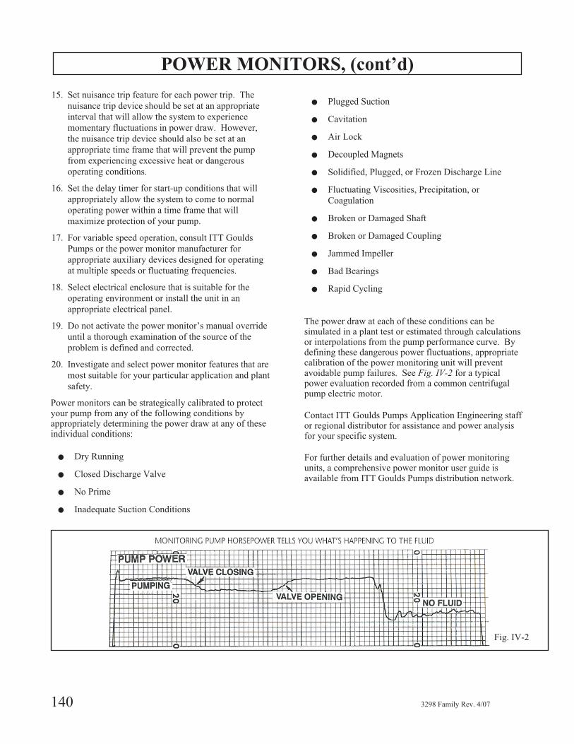
The power draw at each of these conditions can besimulated in a plant test or estimated through calculationsor interpolations from the pump performance curve. Bydefining these dangerous power fluctuations, appropriatecalibration of the power monitoring unit will preventavoidable pump failures. See Fig. IV-2 for a typicalpower evaluation recorded from a common centrifugalpump electric motor.
Contact ITT Goulds Pumps Application Engineering staffor regional distributor for assistance and power analysisfor your specific system.
For further details and evaluation of power monitoringunits, a comprehensive power monitor user guide isavailable from ITT Goulds Pumps distribution network.
140 3298 Family Rev. 4/07
Fig. IV-2

APPENDIX V
Reliability Tips for Operating
Lined Magnetically-Driven Sealless Pumps
QUICK REFERENCE SUMMARY
These summarized reliability guidelines outlinerecommendations for creating an optimal environment foroperating lined mag-drive pumps. For further details onthe subject of operating a lined-mag drive pump withsuperior reliability, please request the Lined Mag-DriveReliability Guide from your ITT Goulds Pumps’representative.
� Do not operate mag-drive pumps under no flow
conditions.
� Do not operate mag-drive pumps against a closed
discharge valve.
� Do not operate mag-drive pumps with solids that
exceed the manufacturer’s maximum limits in particle
size or concentration.
� Before operating mag-drive pumps, confirm chemical
compatibility of process liquid with all wetted pump
components in an effort to reduce corrosion,
permeation, or erosion.
� Do not operate mag-drive pumps with process liquids
that may exceed the maximum temperature limits or
fall below the minimum temperature limits defined by
the pump manufacturer.
� Do not operate mag-drive pumps outside of the
manufacturer’s recommended operating range.
Otherwise, recirculate adequate flow through bypass
lines when operating near or below the manufacturer’s
recommended mechanical and thermal operating flow
to prevent excessive temperature rise or recirculation
cavitation.
� Consider the inner and outer magnet assemblies’
material temperature limits and recoverable flux
density losses due to increased temperatures.
� Do not operate mag-drive pump without considering
the process liquid’s vapor pressure characteristics over
the temperature range of the application. Adequate
NPSHa as well as vapor pressure is mandatory to
prevent cavitation or vaporization in localized low
pressure regions within the pump.
� Use power monitoring devices when potentially
operating near or outside of the manufacturer’s
recommended operating envelope.
� Consider temperature controlling devices such as heat
jackets or steam tracing for pumps that are subject to
process fluids that transform characteristics such as
viscosity, specific gravity, crystallization, coagulation,
solidification, or vaporization with variable process
temperatures.
� Use temperature monitoring devices such as
thermocouples, RTDs, temperature controllers, or
thermometers when process fluid is susceptible to
critical variations in temperature.
� Use leak detectors such as fiber optic sensing devices
or pressure monitoring devices when fluid is prohibited
from entering the atmosphere.
� Ensure selected motor torque at maximum power and
start-up conditions for corrected hydraulic and
magnetic loss power at worst case fluid specific gravity
and viscosity is less than the magnet break-away torque
at maximum temperature.
� Keep process liquid in liquid form. Prevent the liquid
from flashing.
� Do not exceed the manufacturer’s maximum viscosity
limits as internal fluid circulation velocities will be
inadequate to properly cool and lubricate sleeve
bearings.
3298 Family Rev. 4/07 141
8

142 3298 Family Rev. 4/07

APPENDIX VI
Polyshield® ANSI Combo
Installation, Operation, and Maintenance Instructions
SAFETY CONSIDERATIONSSeveral important general precautions are listed below:
1. Do not remove the Polyshield® ANSI Combo from its
shipping pallet until you are ready to hoist it onto its
location.
2. Do not subject the Polyshield® ANSI or Custom
Combo to rough handling or unnecessary mechanical
shock.
3. Do not attempt to lift the Polyshield® ANSI Combo
by any means other than that which is prescribed in
these procedures.
4. Do not use hammer blows or other impact loading to
adjust the positioning of the Polyshield® ANSI
Combo. Do not pry against the Polyshield® mounting
block when moving the motor during shaft alignment.
5. Do not attempt to transport, handle, or install a
Polyshield® ANSI Combo when ambient temperature
is below -50° F (-45° C).
6. Do not operate a pump installed on a Polyshield® ANSI
Combo at process fluid temperatures in excess of 300° F
(150° C) with polymer mounting pads and 500° F with
alloy mounting pads unless prior approval from ITT
Industries - Goulds Pumps is obtained in writing.
� Service temperature in an ATEX classifiedenvironment is limited by Table 1 in the SafetySection.
NOTE: Always coordinate installation activity withoperations personnel, and follow all plant safetyrequirements and applicable safety and health laws,directives and regulations.
OVERVIEW
� CAUTION
Observance of proper handling procedures duringinstallation is extremely important to prevent damageto the Polyshield
®ANSI Combo. While polymer
concrete possesses inherent high strength, subjecting itto impact or bending loads through rough handling orimproper lifting or mounting may result in irreparabledamage to the Polyshield
®ANSI Combo as well as
damage to the mounted equipment or injury topersonnel.
APPLICATIONThe polymer concrete material used in the manufacture ofthe Polyshield® ANSI Combo has been formulated forapplication in a wide range of corrosive fluid handlingservices. The material is not, however, universallycorrosion resistant. A comprehensive corrosion guide isavailable. (Refer to Accessories Section of the ElectronicPricebook.) It is strongly recommended that this bulletinbe reviewed prior to specifying or installing a Polyshield®
Product.
The Polyshield® ANSI Combo is also suitable forapplication in a wide range of fluid process temperatures,specifically, -50° F to 300° F (-45° C to 150° C).Depending on the configuration of the pump that is to bemounted on the Polyshield®, fluid process temperature inexcess of 300° F (150° C) may be permissible. Contactyour ITT Industries - Goulds Pumps representative forassistance in determining acceptability of a specificapplication.
STORAGEThis section addresses the storage procedures for thePolyshield® ANSI Combo only. When storingPolyshield® ANSI Combos and pump assemblies, it isimportant that the proper storage procedures for the pumpbe observed as well. Refer to the Installation, Operationand Maintenance Instructions (IOM) for the particularGoulds pump that is mounted on your Polyshield®
product.
Polyshield® normal packaging is designed to protect thePolyshield® ANSI Combo during shipment and handlingfrom the time it is manufactured at the factory toinstallation at the end user’s job site. If the Polyshield®
Combo is to be stored for a period of time prior toinstallation, it is recommended that the followingprocedures be followed:
a. Leave the Polyshield® ANSI Combo strapped to its
wooden shipping pallet.
b. Place the pallet on a solid, dry, level surface in a
location where the ANSI Combo cannot be struck by
passing fork trucks, falling objects, etc. Make sure
the pallet does not rock.
c. Do not stack heavy objects on top of the Polyshield®
ANSI Combo.
d. If the Polyshield® ANSI Combo is to be stored in an
3298 Family Rev. 4/07 143
8

outdoor location, cover the Polyshield® completely
with a tarpaulin or dark plastic sheeting to prevent
UV degradation of the surface.
NOTE: UV degradation (bleaching) of the polymerconcrete is the normal result of exposure to sunlight.This phenomenon is purely a visible change in thecolor of the material, which in no way compromisesthe performance or corrosion resistancecharacteristics of the Polyshield®.
�! WARNINGDo not attempt to stand a Polyshield
®on its
end to make more efficient use of storage space.Neither the Polyshield
®Combo nor the strapping that
holds the Polyshield®
Combo to its wooden pallethave been designed for vertical storage. Severepersonal injury or death, as well as irreparabledamage to the Polyshield
®Combo may result if the
Combo tips over.
Lifting Polyshield®
Combo Units and Polyshield®
Combo / Pump Assemblies
� CAUTION
Polyshield®
units should be transported viafork truck to the area of their intended installation onthe wooden pallets on which they were shipped. Nevertransport a Polyshield
®unit over a long distance or
over rough terrain while suspended from slings.
Only trained personnel should do lifting. Pumps andmotors often have integral lifting eyes or eye bolts.These are intended for use in lifting the individualpieces of equipment. Do not use these features to lift aPolyshield
®Combo / pump assembly.
Lifting
The following procedures are recommended for liftingPolyshield® ANSI Combo units:
Polyshield® with no mounted equipment:
�! WARNINGDo not install eyebolts in the Polyshield
®thread
inserts for the purpose of lifting the base. Thispractice imposes lateral loads on the inserts — whichthey were not designed to withstand.
Remove the metal shipping straps that hold thePolyshield® unit to the wooden pallet. Slip slings undereach end of the Polyshield® unit as a harness (Fig. VI-1).
Lift the Polyshield® unit a few inches off the pallet andverify that it hangs reasonably level and that the slings arenot prone to slipping out of position.
�! WARNINGKeep hands and feet out from under the Polyshield
®
unit during these steps. If slings slip and the unit tipsover, severe personal injury or death may result, aswell as irreparable damage to the Polyshield®Combo.
If the sling appears to be unstable, set the Polyshield® unitback on the pallet and reposition the slings.
After satisfactory slinging has been achieved, thePolyshield® unit may be hoisted onto its foundation.Take care not to bump the unit against fixed objects orinduce any unnecessary shock loads. Lower the unitslowly over the foundation using care to center the unitover the rebar cage. Place shim packs or wedges under thePolyshield® unit at a minimum of eight total or (four [4]locations on each side) to allow for the removal of theslings. Twelve (12) total shim locations or (six [6] shimlocations each side are required for Polyshield® unitsexceeding six feet in length.
POLYSHIELD®
WITH INSTALLEDEQUIPMENT:
Pump and motor installed:
Remove the metal shipping straps that hold thePolyshield® unit to the wooden pallet. Slip slings undereach end of the Polyshield® unit. This procedure isrecommended up to the MTX or LTX pump units. Allmotors up to a 364T NEMA frame may be installed whilemounted. Motor frame sizes 365T or larger should beremoved during locating and installation of thePolyshield® ANSI Combo units. Check to see that thepump suction nozzle does not interfere with the liftingsling. If the pump creates interference, it should beremoved. Lift the Polyshield® ANSI Combo a few inchesoff the pallet and verify that it hangs reasonably level andthat the slings are not prone to slipping out of position.
144 3298 Family Rev. 4/07
Fig. V-1

After satisfactory slinging has been achieved, thePolyshield® ANSI Combo may be hoisted onto itsfoundation. Take care not to bump the unit against fixedobjects or induce any unnecessary shock loads. Lowerthe unit slowly over the foundation using care to centerthe unit over the rebar cage. Place shim packs or wedgesunder the Polyshield® unit at a minimum of eight total (orfour [4] locations on each side) to allow for the removalof the slings. Twelve (12) total shim locations (or six [6]shim locations each side) are required for Polyshield®
units exceeding six feet in length.
INSTALLATION
General Description of the Polyshield®
ANSI Combo
The Polyshield® ANSI Combo is a solid, polymerconcrete foundation and baseplate shell that ismanufactured in versions that conform to accommodateASME/ANSI B73.1 pumps.
Polyshield® ANSI Combo units are manufactured in fiveprimary sizes with integral catch basins and removablemotor mounting blocks.
Metallic thread inserts are provided in the mountingsurface for the particular combination of pump and motorthat the Combo is intended. The metallic thread inserts onthe pump end are available in 316SS (18.8 CrNi stainlesssteel), Alloy 20 (A744, CN-7M) and Hastelloy C 276(A494, CW-6M). Multiple motor insert patterns are alsoavailable to accommodate more than one NEMA framesize. The standard thread insert material for the motor endis 316SS (18.8 CrNi stainless steel).
Optional alloy pads are available instead of metallicinserts for requirements that call for 0.002”/ft. and orprocess temperatures between 301° F and 500° F.
Polyadjust Motor Block Adjuster System
The Polyshield® ANSI Combo utilizes as standard theunique Polyshield® Polyadjust motor mounting system(Fig. VI-2). This system is comprised of a one-piecepolymer concrete motor mounting block having surfaceflatness and parallelism equivalent to machine steelblocks. The Polyadjust motor mounting block systemincorporates the Polyloc Transverse Jack Bolt system.The Polyloc system provides transverse motoradjustment. The side-mounted adjusters allow for shaftalignment to critical tolerances with minimal disturbanceof indicators. The adjusters make contact with a solidmotor mounting block not the foot of the motor.
Polyshield®
ANSI and Custom Combos InstallationProcedures (NEW CONSTRUCTION)
1. Remove laitance and form grease and oil from area
where the Polyshield® ANSI Combo will be located
using mechanical means, abrasive blasting, or water
blasting. Remove any loose debris including fins,
aggregate, or any protruding objects around the
perimeter of the area where the Polyshield ANSI
Combo will rest.
2. Measure the outside dimensions of the Polyshield®
ANSI Combo and subtract 8” from both the width
and length to determine the rebar maximum
dimension, thus providing clearance from the side of
the walls of the ANSI Combo.
3. Drill holes in the existing slab a minimum of four
inches deep for doweling in the vertical rebar rods
allowing a minimum of one inch clearance from the
top of the interior of the Polyshield® ANSI Combo.
Space the rebar rods of 12” centers. Remove dust
and debris from dowel holes and fill with epoxy
adhesive for anchoring the rebar.
4. Allow the epoxy adhesive to cure, and then install
horizontal rebar rods, tying in place with wire.
5. Place the Polyshield® ANSI Combo over the rebar
cage, making adjustments for proper elevation,
orientation relative to piping centerlines. A qualified
millwright should field verify proper position of the
pump mounting pads relative to the centerline of the
suction piping. Appropriate shims may be placed
along the bottom edge of the Polyshield® ANSI
Combo to aid in leveling. Place shim packs or
wedges under the Polyshield® unit at a minimum of
eight total (or four [4] locations on each side) to
allow for the removal of the slings and metal lifting
straps from each end. A minimum of twelve (12)
total shim locations (or six [6] shim locations each
side) are recommended for Polyshield® units
exceeding seven feet in length.
3298 Family Rev. 4/07 145
8
Fig. VI-2

6. Check and verify the dimensions again before the
grouting procedure begins.
7. A low slump standard concrete mix is suitable for
filling the Polyshield® ANSI Combo in new
construction.
8. Seal around the outside bottom perimeter of the
Polyshield® ANSI Combo with a fast setting
hydraulic cement. Two brand name hydraulic
cements are: Water Plug Hydraulic Cement and
Dam-It Non Shrink Hydraulic Cement.
9. Pour the concrete mixture through the grout fill port
on the top of the Polyshield® ANSI Combo using a
concrete vibrator to ensure proper flow of the
concrete. Do not over vibrate as excessive vibrating
leads to larger aggregate settling which will result in
a weak mix.
10. Pour the concrete to the bottom edge of the grout fill
port.
11. Remove any loose debris from around edges of the
grout fill port.
12. Seal grout fill port with grout port plug and
Polyshield® Seal Kit provided.
13. Install pump, motor, and attach lines.
TOOLS FOR INSTALLATION
� Hammer drill with proper size bit
� Worm gear saw with diamond blade (if required)
� Rebar cutters (new installation)
� Concrete mixer
� Concrete vibrator
� Lifting device (for placing Polyshield®
Foundation)
� Hand tools
� Chipping hammer
� Pressure washer or abrasive blast rig as required
� Epoxy adhesive (for setting rebar into concrete slab
– new installation)
� Rebar tie wire
� Fast set cement
POLYSHIELD®
ANSI COMBOSEALING KIT EPOXY NOVOLAC(EN) INSTRUCTIONS
Each Kit contains:
� Polyshield® EN Resin
� Polyshield® EN Hardener
� Stir Sticks
� Latex Gloves
� Instruction Sheet
� MSDS Material Safety Data Sheet
APPLICATION INSTRUCTIONS:The Polyshield® EN Sealing Kit is intended for use in (1)bonding the plug into the grout hole at the top of thecombo and (2) sealing and providing chemical resistancebarrier around the perimeter of the pump pad.
1. All surfaces to be bonded should be thoroughly
cleaned and should be free of dust, oils and
contaminants. Sand surfaces to be bonded prior to
use.
2. Pour Polyshield® EN Hardener into the Polyshield®
Resin can. Mix well with stir stick for about two
minutes.
3. Apply to properly prepared surface by stir stick or
putty knife.
4. Use MEK, Xylene solvents for cleaning tools and
equipment and for lightly brushing surface to provide
a smooth finish.
SAFETY PRECAUTIONS
�! WARNINGResin and hardener components may be irritating tothe eyes and skin on contact. Vapors may causeirritation of eyes and respiratory tract. Area must beventilated. Wear protective clothing including gloves.For detailed safety information, refer to the MaterialSafety Data Sheets of these products.
146 3298 Family Rev. 4/07
POLYSHIELD®
ANSI COMBOSEALING KIT VINYL ESTER (VE)INSTRUCTIONS
Each Kit contains:
� Polyshield® VE Resin
� Polyshield® VE Hardeners #1
� Stir Sticks
� Latex Gloves
� Instruction Sheet
� MSDS Material Safety Data Sheet
APPLICATION INSTRUCTIONSThe Polyshield® VE Sealing Kit is intended for use in (1)bonding the plug into the grout hole at the top of thecombo and (2) sealing and providing chemical resistancebarrier around the perimeter of pump pad.
1. All surfaces to be bonded should be thoroughly
cleaned and should be free of dust, oils and
contaminants. Sand surfaces to be bonded prior to
use.
2. Pour Polyshield® VE Hardener #1 into the
Polyshield® VE Resin can. Mix well with stir stick
for about two minutes.
3. Apply to properly prepared surface by stir stick or
putty knife.
4. Use MEK, Xylene solvents for cleaning tools and
equipment and for lightly brushing surface to provide
a smooth finish.
SAFETY PRECAUTIONS
�! WARNINGResin and hardener components may be irritating tothe eyes and skin on contact. Vapors may causeirritation of eyes and respiratory tract. Area must beventilated. Wear protective clothing including gloves.For details on safety information, refer to theMaterial Safety Data Sheets of these products.
SHELF LIFE AND STORAGEStore resin and hardener in their unopened containers in adry cool place away from open flames, heat or sources ofignition. Shelf life is limited to 60 days if stored in acool, dry location.
Polyshield® Seal Kits provide sealant for every ANSICombo. Polyshield® Seal Kits are shipped with eachANSI Combo.
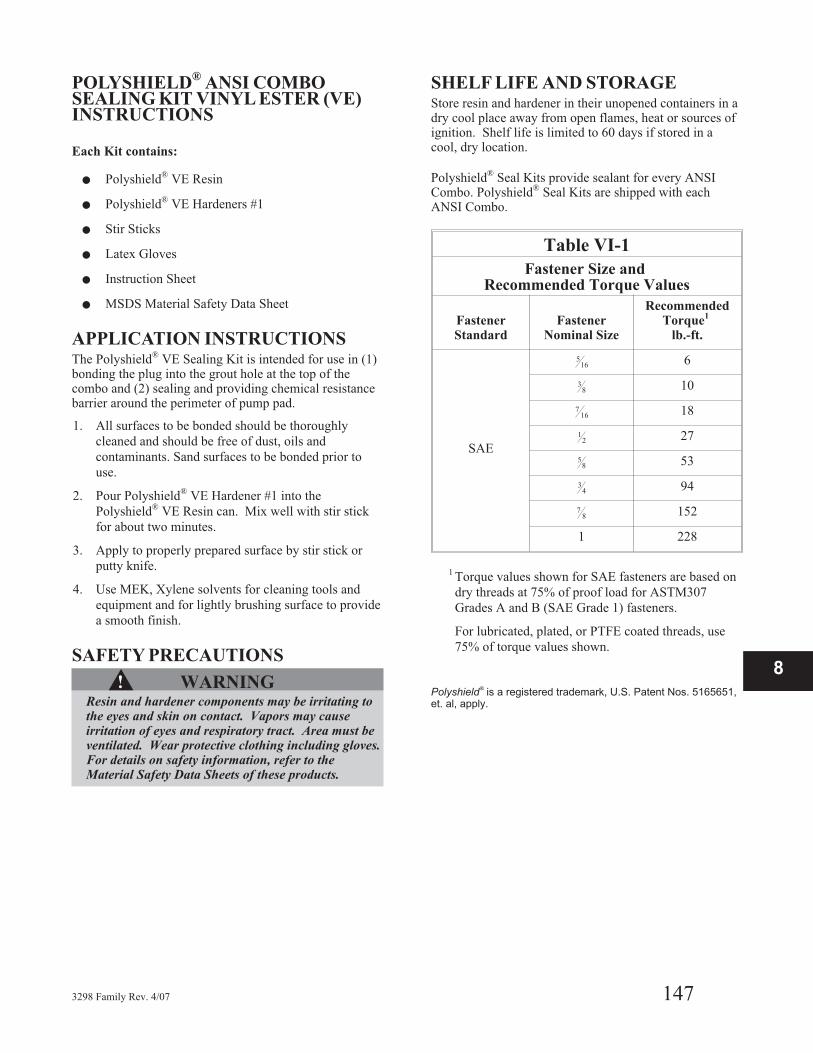
Table VI-1
Fastener Size andRecommended Torque Values
FastenerStandard
FastenerNominal Size
RecommendedTorque
1
lb.-ft.
SAE
516 6
38 10
716 18
12 27
58 53
34 94
78 152
1 228
1 Torque values shown for SAE fasteners are based on
dry threads at 75% of proof load for ASTM307
Grades A and B (SAE Grade 1) fasteners.
For lubricated, plated, or PTFE coated threads, use
75% of torque values shown.
Polyshield®
is a registered trademark, U.S. Patent Nos. 5165651,et. al, apply.
3298 Family Rev. 4/07 147
8

HOW TO ORDER
When ordering parts call
1-800-446-8537
or your local Goulds Representative
EMERGENCY SERVICE
Emergency parts service is available
24 hours/day, 365 days/year...
Call 1-800-446-8537
Form No. I3298 4/07
Visit our website at www.gouldspumps.com
© 2007 Goulds Pumps, Incorporateda subsidiary of ITT Corporation
How did we measure up?It is our sincere intention to exceed our customers' expections on every order.
Tell us whether we achieved our goal on your order.Please take our customer satisfaction survey online at:
http://www.gouldspumps.com/feedbacksurvey.html
We appreciate you taking the time to provide your feedback.Thank you for buying Goulds pumps, parts, and controls.