section 8 air source heat pumps unit 43 air source heat pumps
TRANSCRIPT
SECTION 8
AIR SOURCE HEAT PUMPS
UNIT 43
AIR SOURCE HEAT PUMPS

UNIT OBJECTIVES After studying this unit, the reader should be
able to
• Describe the operation of reverse-cycle refrigeration (heat pumps)
• Explain the function and operation of heat pump system components
• List heat sources commonly used in heat pump systems
• Discuss how heat pump efficiency is determined
• Explain the concepts of coefficient of performance and auxiliary heat
• Describe the control sequence of an air-to-air heat pump system
• Explain how heat pump efficiency can be increased
• Discuss preventive maintenance on a heat pump system

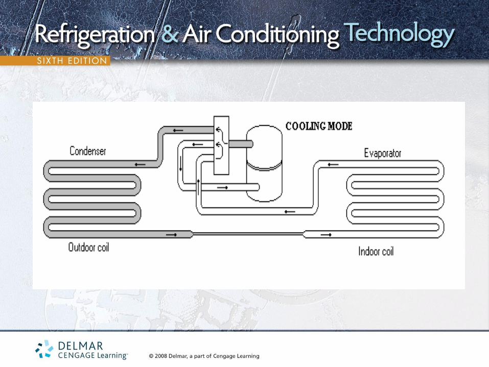
REVERSE-CYCLE
REFRIGERATION • Air-conditioning equipment can only pump heat in one direction
• Heat pumps can pump heat two ways
• Heat pumps have a four-way reversing valve
• Four-way reversing valves control the direction of flow of the
heat-laden vapor between the low- and high-pressure sides of the
system


HEAT SOURCES FOR WINTER
• Air conditioners pump heat from low temperature inside the structure to a
higher temperature outside the house
• There is heat in a substance until it is cooled to -460°F
• At 0°F outside air temperature, there is still 85% usable heat in the air
• Heat pumps have the ability to absorb heat from the structure in the
summertime and discharge it to the outside
• Heat pumps are able to absorb heat from the outside air and discharge it
to the inside of the structure

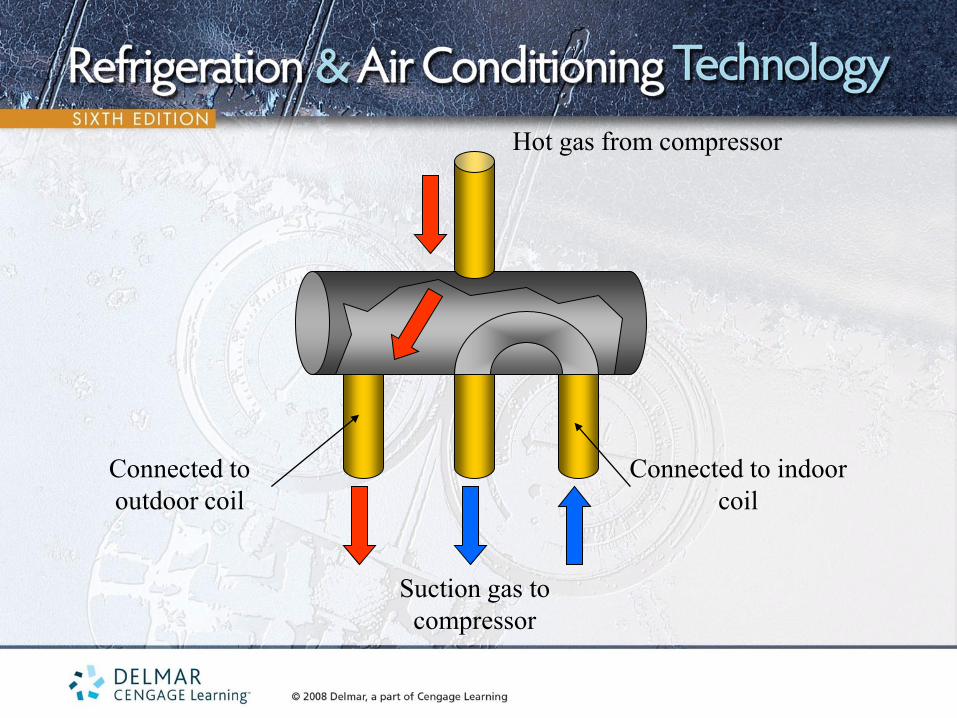
THE FOUR-WAY VALVE
• Allows the heat pump to pump heat in two directions
• Diverts the discharge gas to either heat or cool the conditioned space
• Refrigerant is directed from the compressor to the indoor coil in the heating mode
• Refrigerant is directed from the compressor to the outdoor unit in the cooling mode
• Controlled by the space temperature thermostat
• Pilot-operated valve
• Four piping connections on the valve

Hot gas from compressor
Suction gas to
compressor
Connected to indoor
coil
Connected to
outdoor coil
Moveable slide inside
valve
Direct-acting
reversing valve is
controlled directly by
a solenoid coil

Hot gas from compressor
Suction gas to
compressor
Connected to indoor
coil Connected to
outdoor coil
Pilot-operated
reversing valve is
controlled by the
system pressures
System high
pressure pushes
the slide to the
right
COOLING

Hot gas from compressor
Suction gas to
compressor
Connected to indoor
coil Connected to
outdoor coil
Pilot-operated
reversing valve is
controlled by the
system pressures
HEATING

TYPES OF HEAT PUMPS
• Air is not the only source from which a heat pump ban absorb heat,
but it is the most popular
• Other heat sources for heat pumps include water and Earth
• A typical water-to-air heat pump uses 3 gallons of water per minute in
the heating cycle and 1.5 gallons of water per minute in the cooling
mode per ton of refrigeration

SOLAR-ASSISTED HEAT
PUMPS • These pumps capture heat from the sun
• The heat is then brought to usable levels for heating homes
• Some systems are specially designed to operate in
conjunction with solar heat

THE AIR-TO-AIR HEAT
PUMP • Most popular type
• Basic sealed system components of a heat pump are the
same as an air conditioner, but the terminology changes
• In a heat pump, the terms indoor coil and outdoor coil are used
• The function of each coil changes as the operating mode of
the heat pump changes

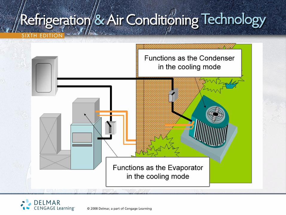
THE AIR-TO-AIR HEAT PUMP
• Function of coils in the cooling mode
– Indoor coil absorbs heat by boiling refrigerant at low temperature
and pressure (evaporator)
– Outdoor coil rejects heat by condensing a high-temperature and
pressure vapor to a high-temperature and pressure vapor
(condenser)
– Refrigerant from the compressor is first pumped to the outdoor
coil
Hot gas from compressor
Suction gas to
compressor
Connected to indoor
coil
Connected to
outdoor coil

THE AIR-TO-AIR HEAT PUMP
• Function of coils in the heating mode
– Outdoor coil absorbs heat by boiling refrigerant at low temperature
and pressure (evaporator)
– Indoor coil rejects heat by condensing a high-temperature and
pressure vapor to a high-temperature and pressure vapor
(condenser)
– Hot gas from the compressor is first pumped to the indoor coil

Hot gas from compressor
Suction gas to
compressor
Connected to indoor
coil
Connected to
outdoor coil


THE AIR-TO-AIR HEAT
PUMP • Mode of operation is determined by which way the hot gas
from the compressor is flowing
• Mode of operation can be determined by touching the gas line
to the indoor coil
– In the cooling mode, the gas line will feel cool
– In the heating mode, the gas line will feel hot

REFRIGERANT LINE IDENTIFICATION
• The large diameter line is called the gas line because only refrigerant vapor flows through it
• The gas line is a cold gas line in the summer and a hot gas line in the winter
• The smaller diameter line is called the liquid line because only liquid refrigerant travels through it
• During the cooling mode, the liquid travels to the indoor coil
• During the heating mode, the liquid travels to the outdoor coil

Indoor Unit Outdoor Unit
HEAT PUMP OPERATING IN THE HEATING MODE
Hot gas from
compressor
High pressure liquid to
metering device and
evaporator

Indoor Unit Outdoor Unit
HEAT PUMP OPERATING IN THE COOLING MODE
Cool suction gas to
compressor
High pressure liquid to
metering device and
evaporator

METERING DEVICES
• Specially designed for heat pump applications
• There must be a metering device at the outdoor unit in the heating
mode
• There must be a metering device at the indoor coil in the cooling
mode

THERMOSTATIC EXPANSION
VALVES (TEV, TXV) • Maintains Desired superheat in the evaporator
• Check valves are piped parallel to the TXV to allow refrigerant to bypass the control when needed
• Heating mode
– The refrigerant flows through the TXV at the outdoor coil
– The refrigerant bypasses the TXV at the indoor coil
• Cooling mode
– The refrigerant flows through the TXV at the indoor coil
– The refrigerant bypasses the TXV at the outdoor coil


THE CAPILLARY TUBE
• Commonly used on heat pumps
• Will allow refrigerant to flow in both directions
• Sometimes two capillary tubes are used with check valves
• There must be a drier/strainer at the inlet of the capillary tube to
ensure that the tube does not get clogged

Ball-type Check Valve

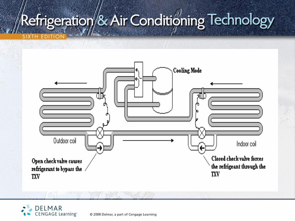
COMBINATIONS OF METERING
DEVICES
• Uses the capillary tube at the indoor coil
– Used in the cooling mode
– Load is relatively constant in the warmer months
• Uses a thermostatic expansion valve at the outdoor coil
– Used in the heating mode
– Allows system to reach maximum efficiency quickly

ELECTRONIC EXPANSION
DEVICES • Can meter refrigerant in both directions
• If indoor and outdoor coils are close together, one device can be
used
• The correct superheat will be maintained in both heating and cooling
modes

ORIFICE METERING DEVICES
• Used in conjunction with check valves
• One device is located at each coil
• The bore at the indoor coil is larger than the bore at the
outdoor coil
• Normally used with a bi-flow filter drier

LIQUID LINE ACCESSORIES
• Two standard filter driers can be used on systems with check valves
– Only one drier will be in the refrigeration circuit at a time
– They are installed with the arrows pointing in the same direction as the check valves
• Bi-flow filter driers
– Two driers in one
– Designed for heat pump applications

Check valve
closed
Refrigerant from outdoor coil
Refrigerant to indoor coil
COOLING MODE

Check valve
closed
Refrigerant to outdoor coil
Refrigerant from indoor coil
HEATING MODE

APPLICATION OF THE AIR-TO-AIR HEAT
PUMP • Usually installed in milder climates (temperatures as low as 10°)
• In the winter, the outdoor coil absorbs heat
• Difference between outdoor and evaporator temperature is about 25°
• If outside temperature is 10°, the refrigerant boils at approximately -15°
• The compressor and the system lose efficiency as the evaporator temperature goes down
• The system loses capacity as the outside temperature drops

AUXILIARY HEAT
• Required when the heat pump cannot provide all the heat a structure needs
• The heat pump is the primary heat source
• Auxiliary heat could be electric, oil or gas
• Electric heat is the most common auxiliary heat used
• As the outside temperature drops, the structure requires more heat

BALANCE POINT
• Balance point occurs when the heat pump can pump in exactly as much heat as the structure is leaking out
• Above the balance point, the heat pump will cycle on and off
• Below the balance point, the heat pump will run continuously and second stage (auxiliary) heat will be energized

COEFFICIENT OF PERFORMANCE
• One watt of usable heat is supplied for each watt of energy purchased
– Using electric resistance heat
– This is called 100% efficient
– Coefficient of performance (COP) of 1:1
– The output is the same as the input
• Air-to-air heat pumps can have a COP of 3.5:1
– When 1 watt of electrical energy is used by the compressor, it can furnish 3.5 watts of usable heat (COP is 3.5:1)

COEFFICIENT OF PERFORMANCE
• High COP only occurs during higher outdoor winter temperatures
• A heat pump’s COP falls as the outdoor temperature falls
• A typical air-to-air heat pump has a COP of 1.5:1 at 0°F
• Some manufacturers have controls to shut off the compressor at
temperatures of 0 to 10°F
• Water-to-air heat pumps might not need auxiliary heat since the heat
source (water) temperature is constant
• Water-to-air heat pumps have a COP rating as high as 4:1

SPLIT-SYSTEM AIR-TO-AIR
HEAT PUMPS • Air-to-air systems can be split or package type
• Both heat pumps and straight cooling units look identical
• Split systems require the installation of the gas and liquid refrigerant
lines to connect the indoor and outdoor units


THE INDOOR UNIT • The part of the system that circulates the air within the structure
• It contains the fan and coil and often the electric strip heaters
• The refrigerant coil must be located in the airstream before the
auxiliary heating coil
• The indoor unit may be a gas or oil fired furnace

THE INDOOR UNIT
• If gas or oil furnace is the indoor unit, the coil must be located in the
outlet airstream of the furnace
• If a gas or oil furnace is used, the heat pump will not operate when
they are operating
• Heat pumps added to electric furnaces should have the coil located
after the heat strips
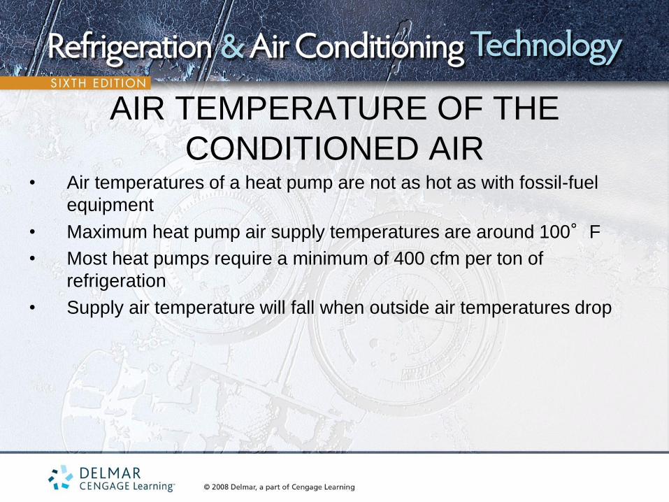
AIR TEMPERATURE OF THE
CONDITIONED AIR • Air temperatures of a heat pump are not as hot as with fossil-fuel
equipment
• Maximum heat pump air supply temperatures are around 100°F
• Most heat pumps require a minimum of 400 cfm per ton of
refrigeration
• Supply air temperature will fall when outside air temperatures drop


THE OUTDOOR UNIT INSTALLATION • Much like a regular air-conditioning installation
• Must have good air circulation around it
• Prevailing winds affect performance
• In the wintertime, the outdoor coil will collect moisture and the moisture
will freeze on the coil
• Outdoor coil should be installed so it is raised above the ground pad to
allow defrost water to run to the ground
• A defrost system is provided to defrost the ice from the outdoor coil

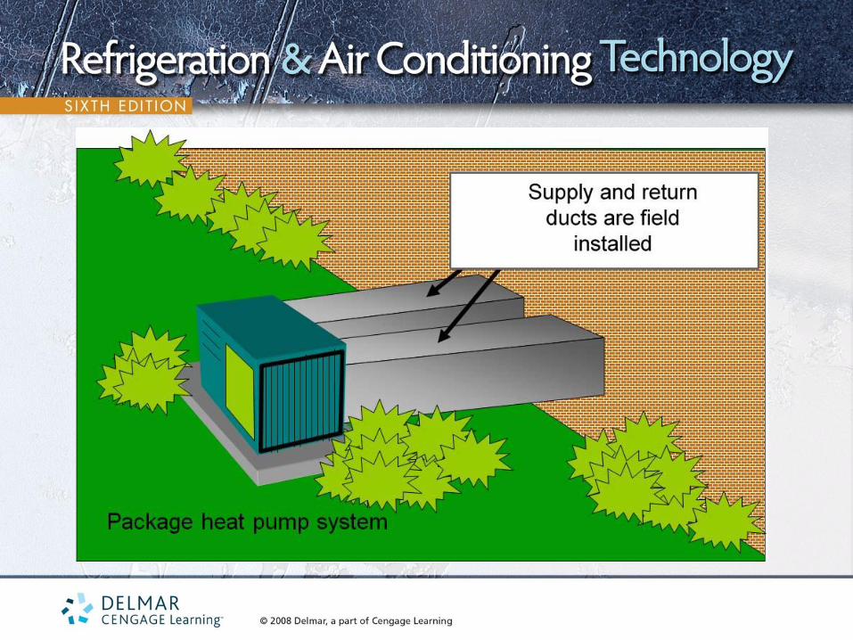
PACKAGE AIR-TO-AIR HEAT PUMPS
• Has all the sealed system and electrical components in one
housing
• Works much the same way as a packaged air-conditioning unit
• Only one power supply required
• Supply and return ductwork must be field installed

CONTROLS FOR AIR-TO-AIR HEAT PUMPS
• Controls are different than other heating/cooling equipment
• In a heat pump, there are two heating systems and one cooling system
• Auxiliary heating system must be operated as a system by itself in case the heat pump fails
• Auxiliary heat is referred to as emergency heat when used because of heat pump failure
• The space thermostat is the key to controlling the system
• Normally, a two-stage heating and two-stage cooling thermostat is used

CONTROLS FOR AIR-TO-AIR HEAT PUMPS
• Automatic changeover thermostat changes automatically between
heating and cooling modes
• Cooling cycle controls
– Thermostat contacts control the operation of the compressor,
outdoor fan motor, and reversing valve coil
– When the thermostat is satisfied, the compressor, outdoor fan
motor, and indoor fan motor are de-energized
– The reversing valve solenoid coil remains energized

Heat Cool 1ST 1ST
2ND 2ND
H(Y)
1(W)
O
C(Y)
FIRST STAGE COOLING (SIMPLIFIED)
Outdoor unit
4-way reversing valve
coil energized
R
O

Heat Cool 1ST 1ST
2ND 2ND
H(Y)
1(W)
O
C(Y)
SECOND STAGE COOLING (SIMPLIFIED)
Outdoor unit
4-way reversing valve
coil energized
R
O
Y
Compressor contactor
coil energized
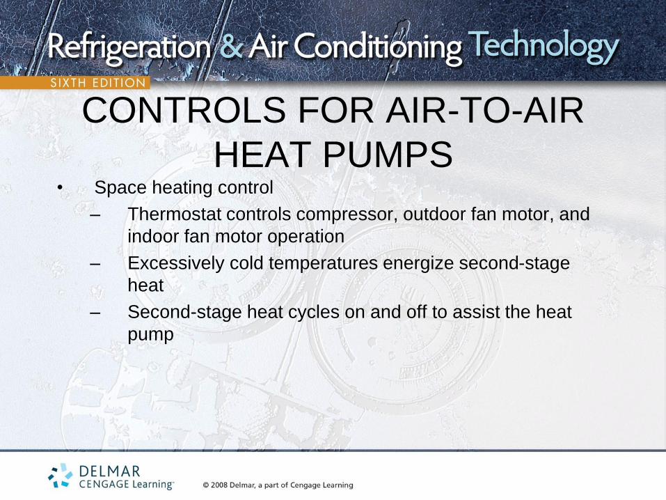
CONTROLS FOR AIR-TO-AIR
HEAT PUMPS • Space heating control
– Thermostat controls compressor, outdoor fan motor, and
indoor fan motor operation
– Excessively cold temperatures energize second-stage
heat
– Second-stage heat cycles on and off to assist the heat
pump

Heat Cool 1ST 1ST
2ND 2ND
H(Y)
1(W)
O
C(Y)
FIRST STAGE HEATING (SIMPLIFIED)
Outdoor unit
R
Y
Compressor contactor
coil energized

Heat Cool 1ST 1ST
2ND 2ND
H(Y)
1(W)
O
C(Y)
SECOND STAGE HEATING (SIMPLIFIED)
Outdoor unit
R
Y
Compressor contactor
coil energized
Heat Cool
1ST 1ST
2ND 2ND
H(Y)
1(W)
O
C(Y)
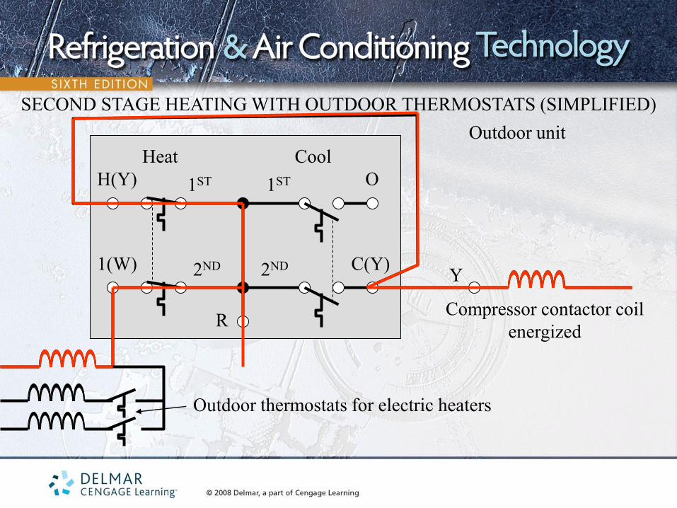
SECOND STAGE HEATING WITH OUTDOOR THERMOSTATS (SIMPLIFIED)
Outdoor unit
R
Y
Compressor contactor coil
energized
Outdoor thermostats for electric heaters

CONTROLS FOR AIR-TO-AIR
HEAT PUMPS • Balance point
– Point at which the heat pump can satisfy the load without shutting
down
– May be multiple balance points
• Electric heaters are energized at different temperatures
– Only the minimum number of heaters is energized at a time
– Conserves energy
– Auxiliary heat operation indicated by signal light on thermostat

CONTROLS FOR AIR-TO-AIR HEAT PUMPS
• Emergency heat mode
– Used in the event of heat pump failure
– All heating elements are energized
– Signal light on thermostat
• Heat anticipators
– Found on heat pump thermostats and conventional thermostats
– Most heat pump thermostats are equipped with two

EMERGENCY HEATING (SIMPLIFIED)
Heat
1ST 1ST
2ND 2ND
H(Y)
1(W)
O
C(Y)
R
Emergency heat relay
contacts
Cool

THE DEFROST CYCLE
• Defrosts ice from outside coil during winter operation
• Outdoor coil operates below freezing anytime the outside air is below 45°F
• Outdoor coil operates 20° to 25°F below the outside air temperature
• The need for defrost varies depending on outside air temperatures and conditions
• The more moisture in the air, the more frost that forms on the outdoor coil
• Defrost affects the efficiency of the systems

HEATING SEASONAL
PERFORMANCE FACTOR
(HSPF) • Seasonal performance for particular piece of equipment
• Breaks the country into six zones
• Used to calculate operation costs
• Considers average number and length of defrost cycles per year
• Considers whether auxiliary heaters are energized during defrost
• SEER and HSPF are results of federal energy policies
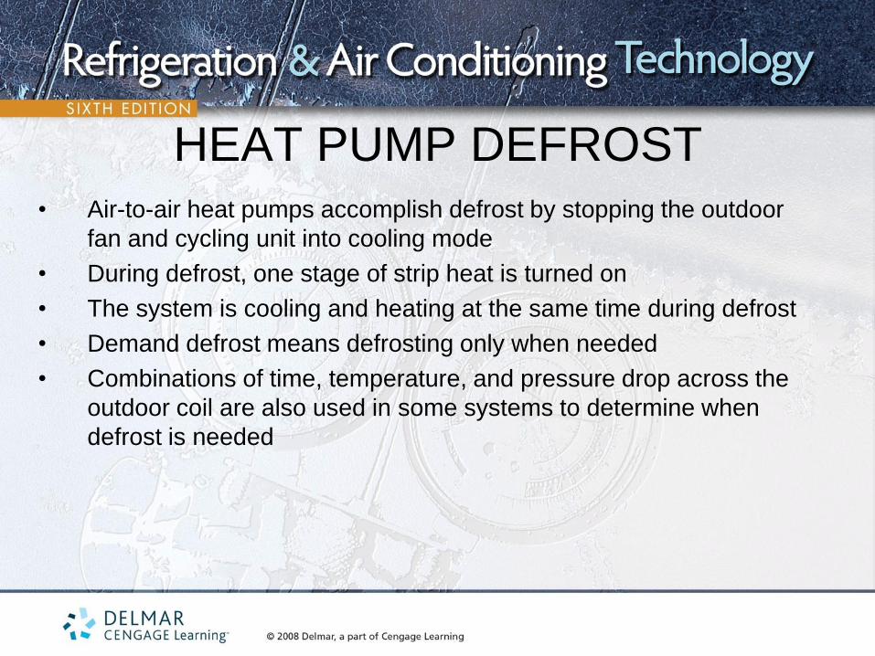
HEAT PUMP DEFROST • Air-to-air heat pumps accomplish defrost by stopping the outdoor
fan and cycling unit into cooling mode
• During defrost, one stage of strip heat is turned on
• The system is cooling and heating at the same time during defrost
• Demand defrost means defrosting only when needed
• Combinations of time, temperature, and pressure drop across the
outdoor coil are also used in some systems to determine when
defrost is needed
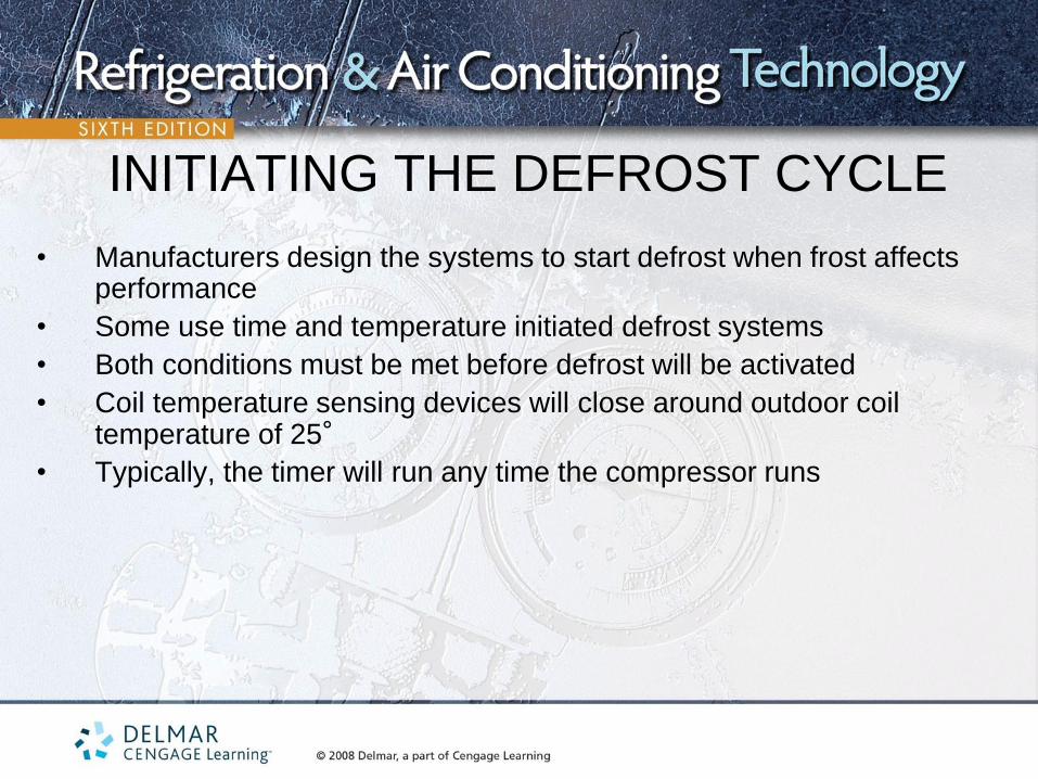
INITIATING THE DEFROST CYCLE
• Manufacturers design the systems to start defrost when frost affects performance
• Some use time and temperature initiated defrost systems
• Both conditions must be met before defrost will be activated
• Coil temperature sensing devices will close around outdoor coil temperature of 25°
• Typically, the timer will run any time the compressor runs

4-way reversing valve
coil
L1 L2
Timer motor
Defrost relay
Outdoor fan Outdoor coil thermostat
TIME AND TEMPERATURE INITIATED DEFROST

INITIATING THE DEFROST CYCLE
• Some systems will also include a pressure switch along with the
temperature and timer function
• When ice forms on the coil, the pressure switch closes
• Time, temperature, and pressure defrost systems ensure that there is
ice buildup on the outdoor coil

4-way reversing valve
coil
L1 L2
Timer motor
Defrost relay
Outdoor fan Outdoor coil stat
TIME, TEMPERATURE AND PRESSURE INITIATED DEFROST
Pressure

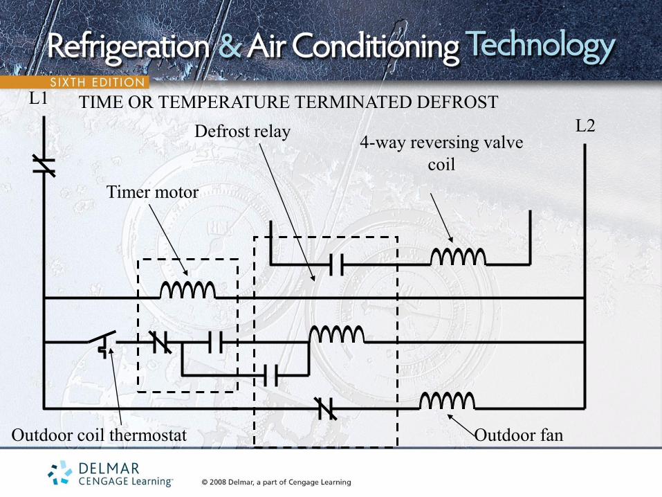
TERMINATING THE DEFROST CYLE
• Stopping the defrost is as important as starting the defrost
• Time, temperature, and pressure can all be used to terminate the defrost cycle
• Temperature sensors used for the defrosting function will open at 50°F
• 10 minutes is the normal maximum time allowed for defrost cycle
4-way reversing valve
coil
L1
L2
Timer motor
Defrost relay
Outdoor fan Outdoor coil thermostat
TIME OR TEMPERATURE TERMINATED DEFROST

ELECTRONIC CONTROL OF
DEFROST • Electronic timers and thermistors used to control defrost
• More accurate control than non-electronic methods
• Can incorporate time and temperature features into a single unit

INDOOR FAN MOTOR CONTROL
• In a heat pump, the fan must be started at the beginning of each mode of operation
• The indoor fan is started with the thermostat
• Fan switch terminal function is normally the G terminal on the thermostat
• The indoor fan motor often operates during defrost
– Circulates air to prevent coil freezing
– Air is tempered to prevent cold air from being introduced to the occupied space
AUXILIARY HEAT
• Usually accomplished with electric heat
• Required to assist the heat pump when it cannot provide all the
heat the structure needs
• Also used as emergency heat when the heat pump needs service
• Heaters also energized during defrost

SERVICING THE AIR-TO-AIR HEAT PUMP
• Much like servicing a refrigeration system
• During the cooling mode, system is operating as a high-temperature refrigeration system
• During the heating mode, system is operating as a low-temperature refrigeration system
• Servicing of the system is divided into electrical and mechanical
• The heat pump may run for days and not stop when outdoor temperatures are below the balance point

TROUBLESHOOTING
MECHANICAL PROBLEMS • Can be hard to identify in a heat pump, particularly in winter
operation
• Summer operation of a heat pump is similar to an air-conditioning
unit
• Mechanical problems are solved with gage manifolds, wet-bulb
and dry-bulb thermometers, and air-measuring instruments

TROUBLESHOOTING THE
FOUR-WAY VALVE • Common problems: stuck valve, defection coil and internal
leaks
• Check to see if coil is energized
• A warm coil indicates power is being supplied to the coil
• Place a screwdriver on the surface of the coil to sense magnetic field
• Check for voltage supplied to the coil
• Defective coils can be replaced without changing the entire valve

TROUBLESHOOTING THE
FOUR-WAY VALVE • Four-way valves leaking through can be confused with a compressor
that is not pumping to capacity
• Capacity of the system will not be normal in summer or winter cycles
• Check the temperature of the low-side line, the suction line from the
evaporator, and the permanent suction line between the four-way
valve and the compressor
• In this check, the temperature difference should not be more than
about 3°F

Hot gas from compressor
Suction gas to
compressor
Connected to
indoor coil
Connected to
outdoor coil
50°F
60°F
Leaking reversing valve in
the cooling mode

Hot gas from compressor
Suction gas to
compressor
Connected to
indoor coil
Connected to
outdoor coil
Leaking reversing valve in
the heating mode
30°F
40°F

CHECKING THE CHARGE
• Most heat pumps have a critical refrigerant charge
• If systems are low on charge, technicians must locate and repair leaks
• Caution should be taken when charging systems with suction
accumulators
• Suction accumulators store part of the charge in the winter mode and
will boil out later

CHECKING THE CHARGE
• Sweating suction-line accumulator
– When checking or charging a system, heat the accumulator by
running water over it to drive the refrigerant out of it
– Often the accumulator will frost or sweat at a particular level if
liquid refrigerant is contained in it
SPECIAL APPLICATION FOR
HEAT PUMPS • Use of oil or gas furnaces for auxiliary heat
• More efficient applications than auxiliary electric heat
• The heat pump coil must be installed downstream of the oil or gas heat
exchanger
• The air must flow through the furnace heat exchanger before the heat
pump coil
• The oil or gas furnace must not operate at the same time that the heat
pump is operating
HEAT PUMPS USING SCROLL
COMPRESSORS • Ideally suited for heat pump application because of its pumping
characteristics
• Scrolls do not lose as much capacity as reciprocating compressors
• Scroll compressor pressures are about the same as reciprocating
compressors
• Scroll compressors are discharge gas cooled,

• Scroll compressors have a check valve in the discharge leaving the
compressor to prevent pressures from equalizing through the
compressor during the off cycle
• Scroll compressors normally do not require a suction-line
accumulator because they are not as sensitive to liquid floodback
HEAT PUMPS USING SCROLL
COMPRESSORS

HEAT PUMP SYSTEMS WITH
VARIABLE-SPEED MOTORS • Use of variable-speed motors for the compressor and both fan motors
is the method used to improve system efficiency in heat pump systems
• Sized closer to the heating requirements of the structure at full load and will run at part load and reduced power in warmer months
• Less auxiliary heat is required for these systems
• Variable speed is accomplished with electronically controlled motors

SUMMARY - 1 • Heat pumps can pump heat two ways to provide both heating and
cooling
• Four-way reversing valves control the direction of flow of the heat-
laden vapor between the low- and high-pressure sides of the system
• In the cooling mode, the outdoor coil functions as the condenser and
the indoor coil functions as the evaporator
• In the heating mode, the outdoor coil functions as the evaporator and
the indoor coil functions as the condenser

• Metering devices are located at the inlet of both the indoor and outdoor
coils
• Check valves are used to bypass the metering device that should not be
in the active refrigerant circuit
• Bidirectional or bi-flow filter driers are two driers in a single shell and are
designed for heat pump applications
• In the heating mode, heat pumps lose efficiency as the outside ambient
temperature drops
• Auxiliary heat is required when the heat pump cannot provide all the heat
a structure needs
SUMMARY - 2
• Balance point occurs when the heat pump can pump in exactly as much heat as the structure is leaking out
• Coefficient of performance is the ratio of usable heat (in watts) produced from each watt of energy purchased
• In winter operation, the COP increases as the outside ambient temperature increases
• Split heat pump systems require the installation of gas and liquid lines to connect the indoor and outdoor units
• The indoor unit contains the fan and coil and often the electric strip heaters
SUMMARY - 3

• Maximum air supply temperatures are around 100°F
• Outdoor coil should be installed so it is raised above the ground pad to allow defrost water to run to the ground
• A defrost system is provided to defrost the ice from the outdoor coil
• Package heat pump systems have all system and electrical components in one housing
• There are two heating systems and one cooling system
• Auxiliary heating system must be operated as a system by itself in case the heat pump fails
SUMMARY - 4

• Automatic changeover thermostat changes automatically between heating and cooling modes
• Emergency heat mode is used in the event of heat pump failure
• The need for defrost varies depending on outside air temperatures and conditions
• The more moisture in the air, the more frost that forms on the outdoor coil
• Defrost affects the efficiency of the systems
• Air-to-air heat pumps accomplish defrost by stopping the outdoor fan and cycling unit into cooling mode
SUMMARY - 5
• Combinations of time, temperature, and pressure drop across the outdoor coil are also used in some systems to determine when defrost is needed and when defrost is terminated
• Defrost can also be controlled electronically
• In a heat pump, the fan must be started at the beginning of each mode of operation
• The indoor fan motor often operates during defrost
• During the cooling mode, system is operating as a high-temperature refrigeration system
SUMMARY - 6

• During the heating mode, system is operating as a low-temperature
refrigeration system
• Common reversing valve problems include: stuck valve, defection coil
and internal leaks
• Temperature readings of the reversing valve connections can be
taken to evaluate the valve
• Most heat pumps are critically charged systems
• If the system operated correctly in at least one mode, the refrigerant
charge is correct
SUMMARY - 7

• Oil or gas furnaces can be used for auxiliary heat
• The heat pump coil must be installed downstream of the oil or gas heat exchanger
• Scroll compressor is ideally suited for heat pump applications because of its pumping characteristics
• Scroll compressors normally do not require a suction-line accumulator because they are not as sensitive to liquid floodback
• Use of variable-speed motors for the compressor and both fan motors is the method used to improve system efficiency in heat pump systems
SUMMARY - 8