section 5: m2m wan architectures and...
TRANSCRIPT

1 • CDMA Network Optimization • October 10, 2011 • www.cdg.org
Section 5: M2M WAN
Architectures and
Optimization

2 • CDMA Network Optimization • October 10, 2011 • www.cdg.org
Review General M2M CDMA Network architecture
Explain the capabilities of CDMA systems in addressing the challenges facing the MNOs deploying M2M services
Provide details of signaling and load impact in CDMA systems
Explain standards activities and review solutions proposed for network improvements to support M2M in 3GPP2
Explain the SW issues in M2M Networks
Section Objectives

3 • CDMA Network Optimization • October 10, 2011 • www.cdg.org
General M2M Network Architecture
MNO Domain
M2M Server
AS
Domain

4 • CDMA Network Optimization • October 10, 2011 • www.cdg.org
High Level M2M Network diagram
Smart Energy
M2M Area Network PLC ZigBee M-Bus 802.15.4 Home plug/PLC Etc.
Access Network 1x EV-DO GSM/GFRS UMTS LTE
Core Network 3GPP2 3GPP ATTM
e-Health
Smart Transport

5 • CDMA Network Optimization • October 10, 2011 • www.cdg.org
General M2M Devices and Network Considerations
Network Considerations – Access load, congestion and latency
– Signaling load and latency
M2M apps are chatty
M2M keep alive packets
– Air interface capacity (due to AI resources being held)
– Device reachability for network push data
Device Considerations – M2M devices have different characteristics (one size does not fit all from core network and access
network operation perspectives)
– Different latency requirements for different M2M applications
– Contrasting sleep cycle durations to conserve battery power of the device (some apps on G meters
demand 20 years battery life)
– Devices should provide autonomous operation – maintenance and configuration should be human
free
Security considerations – Authentication, data integrity and protection (end-to-end), cloning, privacy, anonymity, etc.
Power and Storage considerations – Battery life and replacement, sleep modes, temperature, humidity, end-to-end reachability, etc.

6 • CDMA Network Optimization • October 10, 2011 • www.cdg.org
M2M Deployment Impact Summary
• Access congestion due to large number of devices
– In case of system failure, bringing up all the devices is a
big challenge
• M2M service payloads are typically much smaller
than signaling and overhead
• Long inactive/dormant periods
• Uncontrolled message for status report could have
a negative impact on the system loading

7 • CDMA Network Optimization • October 10, 2011 • www.cdg.org
General Solutions
Minimize Impact of M2M Devices on Existing Networks
– Performance optimization by changing parameter settings (CDMA is extremely
friendly for this purpose)
– Improve transmission efficiency (SMS on paging channels vs. Traffic Channel
as an example)
– Efficient parameter setting in the device
Efficient device settings for slot cycle/battery conservation
Registration / low mobility network timer settings
Improve Network Capacity
– Network optimization (upgrade to 1X Advanced for additional capacity)
– Optimization of network for M2M devices
Dedicated RF channel for M2M devices (easily done in CDMA)
Smaller packet sizes
– Shorter packets, i.e., 5 msec packets instead of 20 msec
– Enhanced access channel operation in CDMA

8 • CDMA Network Optimization • October 10, 2011 • www.cdg.org
1X Signaling
and Traffic Load Analysis
1X Signaling
and Traffic Load Analysis

9 • CDMA Network Optimization • October 10, 2011 • www.cdg.org
CDMA2000 1x Voice Service Network Impact
Signaling
Load
Traffic
Load
%
Sig/Traffic
Total
Load
Voice Call Usage
5 Second Voice call 880 5120 17.19 6000
10 Second Voice Call 1100 10900 10.09 12000
20 Seconds Voice Call 1400 22600 6.19 24000
1 Minute Voice Call 3950 68050 7.22 72000
2 Minute Voice Call 7890 136130 3.62 144000
Signaling and Traffic Loads For Various Voice Call Lengths

10 • CDMA Network Optimization • October 10, 2011 • www.cdg.org
Signaling Load Impact on a 1X Voice Call

11 • CDMA Network Optimization • October 10, 2011 • www.cdg.org
Network (Air Interface) Loading with 1X Voice Calls
For a CDMA2000 1X voice call, the average signaling load in the forward link is around 6% and in the reverse link is around 7.5%
– The signaling load gets converged to such average value (of 6/7.5%)
only after 18 seconds from the start of the call
In 1X networks, voice call set up time is between 3 to 6 seconds
– Network utilization for the call set up time period is not being charged
– To compensate for the non-chargeable part of the call, the minimum
duration of an economical voice call has to be beyond the signaling
convergence time of 18 seconds
Signaling load can be less than the normal 6% for non-mobility M2M calls due to lesser number of hand-off related signaling messages

12 • CDMA Network Optimization • October 10, 2011 • www.cdg.org
Signaling and Traffic Load for Various SMS Calls
Signaling
Load
Traffic
Load
%
Sig/Traffic Total load
SMS size: 20 bytes (Small SMS)
MO SMS sent over ACH (avg 1.2 probes) 60 24 250.00 84
MT SMS sent over PCH (over 21 sectors) 320 420 76.19 740
MO SMS sent over R-TCH 900 20 4500.00 920
MT SMS sent over F-TCH 900 20 4500.00 920
SMS size: 80 bytes (Medium SMS)
MO SMS sent over ACH 60 96 62.50 156
MT SMS sent over PCH 320 1680 19.05 2000
MO SMS sent over R-TCH 900 80 1125.00 980
MT SMS sent over F-TCH 900 80 1125.00 980
SMS size: 160 bytes (Large SMS)
MO SMS sent over ACH 60 192 31.25 252
MT SMS sent over PCH 320 3360 9.52 3680
MO SMS sent over R-TCH 900 160 562.50 1060
MT SMS sent over F-TCH 900 160 562.50 1060

13 • CDMA Network Optimization • October 10, 2011 • www.cdg.org
Comparison of Total Network Load (SMS and Signaling)
When Sent over Different Channels

14 • CDMA Network Optimization • October 10, 2011 • www.cdg.org
Network (Air Interface) Load details for 1X SMS Call
From the network utilization point-of-view, sending SMS msgs over overhead
channels (i.e., Access Channel for mobile originated & Paging channel for the
mobile terminated SMSs) is more economical
– It is assumed that on an average it takes 1.2 access probes to send a message on
the access channel
– It is assumed that on an average a page gets sent over 21 sectors (i.e., a page to a
mobile actually gets paged on the paging channels of around 21 sectors, thus loading
PCHs of 21 sectors)
– Because there is no power control during SMS operation on ACH/PCH, there is no
control over the interference effects also
Sending SMS msgs over traffic channels is more secure (i.e., preserves the
integrity)
– But, from the signaling load perspective, SMS over TCHs is at least 3 to 4 times less
economical
1X Advanced networks with R-EACH and F-CCCH can help to solve the
disadvantages of sending SMS msgs over overhead channels

15 • CDMA Network Optimization • October 10, 2011 • www.cdg.org
1 Minute Data Call Overhead at Various Data Rates
Signaling
Load (bytes)
Traffic
Load
(bytes)
%
Sig/Traffic
Total load
(bytes)
1 Minute CDMA2000 1X Packet Data Call at Different Data Speeds
15 kbps 6300 106200 5.93 112500
30 kbps 8760 216240 4.05 225000
45 kbps 9530 328970 2.90 337500
60 kbps 9620 440380 2.18 450000

16 • CDMA Network Optimization • October 10, 2011 • www.cdg.org
Signaling Trends in 1X Data Calls

17 • CDMA Network Optimization • October 10, 2011 • www.cdg.org
Network (Air Interface) Loading with 1X Data Calls
For a 30 kbps data call in CDMA2000 1X network, the average signaling
load in the forward link is around 3.5% and in the reverse link is around
2.5% – The signaling load gets converged to such average value (of around 3%) only
after 15 seconds from the start of the call
In 1X networks, data call set up time is between 4 to 7 seconds – Network utilization for air-interface call set up time is generally not charged
– To compensate for the non-chargeable part of the call
The minimum duration for an economical data call has to be beyond the signaling convergence time of 15 seconds or
The minimum data rate for an economical data call has to be beyond 7 k bytes
Signaling load can be less than the normal 3% for non-mobility M2M
data calls due to lesser number of hand-off related signaling messages

18 • CDMA Network Optimization • October 10, 2011 • www.cdg.org
Signaling & Traffic Load with an LBS call on 1X Data Network
Signaling
Load
Traffic
Load
%
Sig/Traffic
Total
load
Location Determination
Each seed – MS Assisted 1500 600 250% 2100
Each Seed – MS Based 1500 1000 150% 2500

19 • CDMA Network Optimization • October 10, 2011 • www.cdg.org
Some M2M devices need to send the position location information to the server in every 60 to 90 minutes
In MS assisted mode. This takes 17 to 20 seconds and 2100 bytes of data flow for exchanging a single location information fix (say… between client and the server machines)
In MS based mode, it takes 11 to 14 seconds time and 2500 bytes of data flow for exchanging a single location information fix
From network loading point-of-view, exchanging a single LBS fix is approximately equivalent to sending two SMSs over TCH
Network (Air Interface) Loading with 1X LBS Calls

20 • CDMA Network Optimization • October 10, 2011 • www.cdg.org
Network Impact from EV-DO Rev A Packet Data Call
Signaling
Load
(kbytes)
Traffic
Load
(kbytes)
%
Sig/Traffic
Total load
(kbytes)
1 Minute 1x EV-DO Rev A Data Call at different Data Speeds assuming SectorParameters,
AccessParameters and BroadcastReverseRateLimit message broadcasts every 2 Control Channel cycle
15 kbps 24.120 112.5 21.44 136.67
30 kbps 24.120 225.0 10.72 249.12
45 kbps 24.120 337.5 7.14 361.62
60 kbps 24.120 450.0 5.36 474.12
100 kbps 24.120 750.0 3.21 774.12
200 kbps 24.120 1500.0 1.61 152412
300 kbps 24.120 2250.0 1.07 227412
500 kbps 24.120 3750.0 0.64 377412
1000 kbps 24.120 7500.0 0.32 752412

21 • CDMA Network Optimization • October 10, 2011 • www.cdg.org
Network (Air Interface) Loading with 1xEV-DO Data Calls
For EV-DO data calls, the average amount of signaling is: – ~ 497 Forward and Reverse Link messages
Includes overhead messages, broadcast, and connection setup messages
– 46.97 bytes is the average size of each of the messages
– 24,118 bytes exchanged for signaling in a 1 minute data call
The majority of the signaling is from:
– Overhead msgs (QuickConfig, SectorParameters, Sync, BroadcastRateLimit, Pages)
In EV-DO networks, the air-link connection set up time ranges from 400–600 ms and requires only 5 signaling msgs – Network utilization for the call set up time period is not being charged
If PPP setup is included, an additional 2 – 3 seconds is added to the total setup time
Data can also be sent over the EV-DO access channel using Data over Signaling (DoS) – An IP address is not required

22 • CDMA Network Optimization • October 10, 2011 • www.cdg.org
Signaling Load Trend in an EV-DO Data Call (60 sec duration)
0.00%
5.00%
10.00%
15.00%
20.00%
25.00%
15 kbps 30 kbps 45 kbps 60 kbps 100 kbps 500 kbps 1000 kbps 1500 kbps 2000 kbps 3000 kbps
% S
ign
allin
g Lo
ad o
ver
Traf
fic
Load
Assumed Data Rate (kbps)
Signaling to Traffic Load for a 1 minute EV-DO Data Call

23 • CDMA Network Optimization • October 10, 2011 • www.cdg.org
Data over Signaling (DoS) in EV-DO
Data can also be sent over the EV-DO access channel using Data over Signaling (DoS). The traffic flow is listed below. – DataOverSignaling msg on AC
– DataOverSignalingAck on CC
The maximum data payload in DOS msg depends on the AccessChannel transmission rate, and maximum capsule length, =Maximum payload size of AC transmission rate × CapsuleMaximumLength. – For example, Assume AC transmission rate = 38.4 kbps,
CapsuleMaximumLength =4
– The maximum payload for AC packets is 1000*4 = 4000 bits
The signaling overhead for each DOS pair is fixed, using 4 bytes

24 • CDMA Network Optimization • October 10, 2011 • www.cdg.org
Signaling Load Trend in DOS msgs with Various Data Sizes

25 • CDMA Network Optimization • October 10, 2011 • www.cdg.org
Network (Air Interface) Loading with EV-DO Data Calls
Factors Impacting Signaling Load Description Impact
IP Address Retention If IP address needs to be retained (for paging purposes), then PPP setups are not required every time data needs to be transferred over the air link
Low
EV-DO Paging Load on Network Higher paging load will increase the overhead broadcast signaling on the Forward Link
Medium
NeighborList Design and IFHO Forward Link overhead broadcast signaling will be higher and variable in areas where the NeighborLists are large or Inter-frequency Handoffs are implemented
Neighborlist – Low IFHO – Medium to
High
Subnet Boundaries Subnet boundaries may also have an increase in overhead broadcast Forward Link signaling if session transfers are not graceful
Medium

26 • CDMA Network Optimization • October 10, 2011 • www.cdg.org
3GPP2 Optimization Proposals 3GPP2 Optimization Proposals

27 • CDMA Network Optimization • October 10, 2011 • www.cdg.org
3GPP2 is addressing many issues regarding M2M performance optimization
3GPP2 needs to support
– Complete separation between the access network and M2M
services
– Interworking between 3GPP2 network and M2M service domain
Allowing a M2M service capability with common service
Allowing M2M application server to directly connect to 3GPP2
at core network
Allowing interworking between M2M service domain and
3GPP2 CS core
For details of the proposals please see the back up slides
3GPP2 M2M Performance Optimization Proposals

28 • CDMA Network Optimization • October 10, 2011 • www.cdg.org
Current 1X/EVDO M2M Summary
1X/EVDO networks are increasingly serving M2M devices
– Intent to address key issues and potential solutions for M2M
– High interest by large number of Utilities and other M2M Companies
Current Network Issues
– Need to use CS domain (SMS) to wake up the device if the NW wants to push data
– RAN resources are kept per AT based on inactivity/dormancy timer in relation to application “keep alive” message repetition rate
– PPP session kept on per AT based application “keep alive” message
– Always on PPP session per AT if implemented is already available Having application „keep alive “ will mean additional signaling load when lower layer “always on”
is implemented
– MS battery issues
– Need for fast re-Authentication
• Current Proposals for Optimization – Infrequent data transmission by M2M server
Use PPP less IP connection
Improve battery life of the device
– M2M device connectivity control
– Enables M2M server to download policies for device connectivity rules (access time, etc.) Fast re-authentication Speed up authentication by avoiding full authentication for subsequent PPP establishment (This
proposal is already accepted)
28
Current 1X/EVDO M2M Summary

29 • CDMA Network Optimization • October 10, 2011 • www.cdg.org
Standards Body
Spec / Requirement Description Status
ETSI
M2M identified as a strategic topic and efforts initiated mid-2008
M2M Functional Architecture- ETSI TS 102 690 V<0.1.2> (2010-01)
M2M Service Requirements- ETSI TS 102 689 V0.4.1 (2009-mm)
M2M Smart Metering Use Cases- ETSI TR 102 691 V0.2.1 (2009-12)
M2M Applications for eHealth- ETSI TR 102 732 V0.2.1 (2009-09)
M2M Use cases for Automotive Applications- ETSI TR 102 898 V<0.0.1> (2010-
01), Preliminary
M2M Use cases for City Applications- ETSI TR 102 897 V<0.0.1> (2010-01), Preliminary
Draft
3GPP
Started study report mid-2007. SA1- Services, SA2- Arch & SA3 Security tracks
SA1- M2M Study Report- 3GPP TR 22.868 V8.0.0 (2007-03) Rel. 8
SA1- MTC Service Requirements- 3GPP TS 22.368 V1.1.1 (2009-11) Rel. 10
SA2- System Improvements for MTC- 3GPP TR 23.888 V0.2.1 (2010-01) Rel. 10
SA3- M2M Security Aspects for Remote Provisioning and Subscription Change- 3GPP TR 33.812 V9.0.0 (2009-12) Rel. 9
Published
IEEE
Investigation started late 2009 for traditional and CE devices:
Baseline Requirements for Machine to Machine (M2M) from SPWG: T31-127-R020-v01-E: No work item as yet in NWG Rel 1.6
http://members.wimaxforum.org/apps/org/workgroup/spwg/download.php/52392 Draft
M2M: State of the Standards M2M: State of the Standards

30 • CDMA Network Optimization • October 10, 2011 • www.cdg.org
ETSI M2M Requirements
Overall Aspects of M2M Architecture
– M2M architecture must be access agnostic
– Dynamic bootstrapping of M2M service subscription
and credentials
– Any M2M service can be offered over any access
network which supports ETSI M2M
– No M2M service changes required when moving from
one access network to another
ETSI M2M Requirements

31 • CDMA Network Optimization • October 10, 2011 • www.cdg.org
ETSI Smart Card Platform
ETSI SCP
– Specifies (e)UICC platform capabilities for (e)UICC
– Challenges
Ensure that specified platform capabilities for (e)UICC
are friendly towards TrE realization; e.g.,
– No need to mandate a specific Operating System
– Standardization of app execution environment
sufficient (e.g., Javacard)
Currently dominated by smartcard vendors and
GSMA eSIM Task Force operators
ETSI Smart Card Platform

32 • CDMA Network Optimization • October 10, 2011 • www.cdg.org
3GPP2 Network Entities and Details
SCP=Service Capability Platform
3GPP2 Network Entities and Details
SCP: Service Control Port

33 • CDMA Network Optimization • October 10, 2011 • www.cdg.org
3GPP2 Proposals for Network and Performance
Optimization
M2M Keep Alive
– Issue:
Feature to detect if the device is reachable
– Proposal:
A CN entity notifies M2M server about the device reachability status
M2M Device Keep-Alive Optimization
– Issue:
M2M Application/server may send a frequent keep-alive message to the M2M
device.
– Proposals:
Option 1: Introduce a signaling message from PDSN to M2M IWF to inform
M2M IWF about the device reachability status based on „Always On‟ service
specified in the standards. The IWF sends the signaling message further to the
M2M server through M2Mi interface
Option 2: In addition to option 1, add M2M device proxy function at M2M IWF

34 • CDMA Network Optimization • October 10, 2011 • www.cdg.org
3GPP2 Proposals for Network and Performance
Optimization (continued) M2M Device Connectivity Control
– Issue:
Based on the M2M device category and based on the data type, M2M service
provider and the wireless operator may need to exchange information to
control the WAN connectivity aspects for the M2M device
– Proposal:
Use M2Mi interface to exchange the policies regarding the M2M device WAN
connectivity rules between M2M Server and the M2M-IWF
M2M IWF may further download the device connectivity rules to M2M wireless
aggregation point or M2M device
Fast Re-authentication
– Issue:
Currently, when PPP is established or re-established, full authentication is
required
– Proposal:
Speed up authentication by avoiding full authentication for subsequent PPP
establishment

35 • CDMA Network Optimization • October 10, 2011 • www.cdg.org Source: CDMA2000 Security Overview, CDG, August 2002
• Security and privacy is a major concern for M2M customers
• Customer are concerned with fraudulent operations, such as eavesdropping, cloning,
message interception and subscriptions fraud
• CDMA2000 enhances end-to-end security by using improved encryption algorithms
and other means such as authentication, hashing, data protection and anonymity
• Enhanced security is applied to:
• Enable authentication
• Ensure end-to-end network security
• Prevent cloning
• Eliminate eavesdropping
• Preclude message interception
• Provide anonymity
• Guarantee message integrity
• Safeguard privacy
• Support Public Key Infrastructure (PKI) and digital signatures
CDMA2000 Security Protocols are Among the Best in the Industry.
Security features of CDMA have never been compromised.
Security & Privacy
Security & Privacy

36 • CDMA Network Optimization • October 10, 2011 • www.cdg.org Source: CDMA2000 Security Overview, CDG, August 2002
• CDMA2000‟s unique noise-like signature makes eavesdropping extremely difficult
• Voice and data transmissions are scrambled using a 42-bit PN (pseudo random) “Long Code” that
introduces a noise length sequence of 242 -1
• Data is scrambled at a rate of 19.2 Kilo symbols per second (ksps) and 1.2288 Mega chips per second
(Mcps) on the forward and reverse link, respectively
• For authentication, the standardized CAVE (Cellular Authentication and Voice Encryption)
algorithm is used to generate a 128-bit “Shared Secret Data” (SSD) sub-key with the following
unique variables:
• 64-bit authentication key (A-key)
• 14-digit (56-bit) alpha numeric Mobile Equipment Identifier (MEID) and
• RANDSSD, a random binary number which is generated in the HLR/AC
• The Advanced Encryption Standard, AES (Rijndael) algorithm, AKA (Authentication and Key
Agreement) protocol and Kasumi algorithm are used for encryption and message integrity
• A Secure Hashing Algorithm-1 (SHA-1) is used for hashing and integrity
• For anonymity, a Temporary Mobile Station Identifier (TMSI) is used to make it difficult to
correlate the user to their own mobile transmission
• Standard Virtual Private Networks (VPN), Secure Sockets Layer (SSL) and IPsec security
features are used to ensure end-to-end security throughout the entire network
Security & Privacy Details
Security & Privacy Details

37 • CDMA Network Optimization • October 10, 2011 • www.cdg.org
General Considerations
OS Selection for M2M Devices
General Considerations
OS Selection for M2M Devices

38 • CDMA Network Optimization • October 10, 2011 • www.cdg.org
OS and SW Issues and Considerations
Is OS really important?
– Not every part of the code may be needed for all M2M devices
– Must make sure that you do not break the certification done on the
device
– The value of the M2M devices is rapidly moving from the HW side
to the SW side
– WAN based devices this could be critical for network performance
– Control and diagnostics are very important aspects of the M2M
wireless devices
Need to know if the device is on-line
If not on line, need to know why
Need to be able to remotely activate the device

39 • CDMA Network Optimization • October 10, 2011 • www.cdg.org
OS Selection Pointers
SW needs to be HW agnostic!
BREW Is well fit for many M2M devices
– BREW market penetration may be an issue
Linux is becoming popular
Android is also widely used in M2M devices
Real Time Visualization is also mentioned as a high potential by some
developers!
When developing SW, must decide how much intelligence to put in the device
vs. in the M2M Gateway
– The decision may heavily depend on the application that the device is being used for
– This also requires thorough cost/benefit analysis
Example: Do I pay less for the bytes on the transport side and add the
capability to the device to do the processing locally and then send the results
or do I pay more for the transport and build the intelligence on the gateway?
OS Selection Pointers

40 • CDMA Network Optimization • October 10, 2011 • www.cdg.org
Distributed vs. Centralized
Server side intelligence vs. adding smarts in the MODEM
– Distributed system benefits and shortfalls
Lower transport cost
Higher device cost
Higher SW update/upgrade cost
Network data is better preserved in case of gateway failure
Security might be better in terms of decentralized data
– Centralized network benefits and shortfalls
Higher transport cost
Lower device cost
Easier SW update/upgrade
Security issues
– May be able to better protect the gateway
– However, if compromised the process data could be compromise
There is no one solution that fits all!

41 • CDMA Network Optimization • October 10, 2011 • www.cdg.org
General Issues to Be Considered
Particular application requirements
Latency
QOS
Security
Portability
Power Management

42 • CDMA Network Optimization • October 10, 2011 • www.cdg.org
What are some the impacts introduced to WAN when adding M2M services to the network?
How does the security in CDMA compares with the other technologies?
What are some of the parameters in an IP connectivity of the devices that one needs to consider for network performance optimization?
What are some of the main issues regarding M2M devices in WAN?
In your opinion what OS is best suited for M2M devices? Why?
Section Review

43 • CDMA Network Optimization • October 10, 2011 • www.cdg.org
Back Up Slides
IS-2000 Capabilities
Back Up Slides
IS-2000 Capabilities
44 • CDMA Network Optimization • October 10, 2011 • www.cdg.org
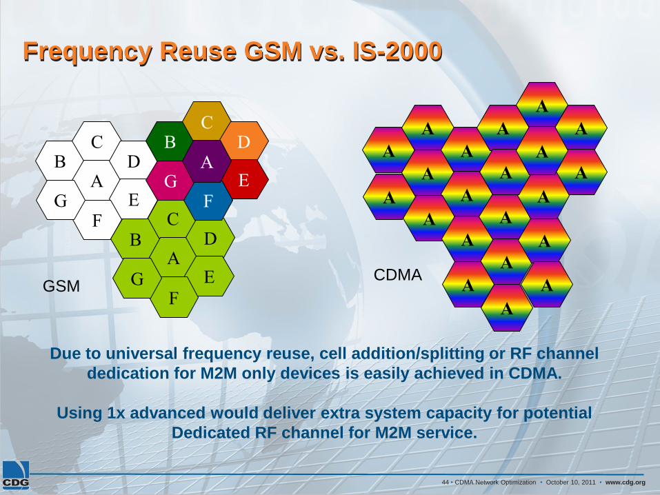
Frequency Reuse GSM vs. IS-2000
B C
A D
E F
G
B C
A D
E
F G
B C
D
E F
G A
A
A
A
A
A
A
A
A
A
A
A
A
A
A
A
A
A
A
A
A
A
GSM CDMA
Due to universal frequency reuse, cell addition/splitting or RF channel
dedication for M2M only devices is easily achieved in CDMA.
Using 1x advanced would deliver extra system capacity for potential
Dedicated RF channel for M2M service.
Frequency Reuse GSM vs. IS-2000

45 • CDMA Network Optimization • October 10, 2011 • www.cdg.org
Control Channel Enhancements for Congestion Control
Every RF channel in CDMA can handle up to 7 paging channels and
every paging channel could support up to 32 access channels. Using
this capability enhances the SMS load distribution and can serve very
large number of M2M devices in a network!
With Slot_Cycle_Index of the device set at 7, the device only needs to
wake up once every 1.28*27 sec or once every 2.73 minutes to receive
instructions. The total wake up time is only 80 msec which can be
further reduced by invoking Quick Paging Channel. This reduces the
power consumption of the device significantly and reduces the
congestion dramatically.
Control Channel Enhancements for Congestion Control

46 • CDMA Network Optimization • October 10, 2011 • www.cdg.org
Paging Channel Structure Slotted Mode (DL)
P a g i n g C h a n n e l
S l o t 0
8 0 m s
. 0 8 s
. 0 8 x R b i t s
M a x i m u m P a g i n g C h a n n e l S l o t C y c l e
S C I
P a g i n g C h a n n e l
H a l f F r a m e B o d y
P a g i n g C h a n n e l
H a l f F r a m e B o d y
P a g i n g C h a n n e l
H a l f F r a m e B o d y
. 0 1 s ´ R - 1 b i t s
M e s s a g e B o d y C R C
= 0 = 1 = 0
2 - 1 1 4 6 b i t s 3 0 b i t s
P a g i n g C h a n n e l
H a l f F r a m e
1 0 m s . 0 1 s ´ R b i t s
8 P a g i n g C h a n n e l H a l f F r a m e s
P a g i n g C h a n n e l M e s s a g e C a p s u l e P a g i n g C h a n n e l M e s s a g e C a p s u l e
P a g i n g C h a n n e l M e s s a g e P a d d i n g
a s r e q u i r e d
P a g i n g C h a n n e l M e s s a g e P a g i n g C h a n n e l M e s s a g e P a d d i n g
a s r e q u i r e d
F i r s t N e w C a p s u l e i n S l o t , S y n c h r o n i z e d
C a p s u l e
A b u t t e d M e s s a g e s , U n s y n c h r o n i z e d
C a p s u l e s
S y n c h r o n i z e d C a p s u l e s
P a g i n g C h a n n e l
H a l f F r a m e B o d y
= 0
P a g i n g C h a n n e l
H a l f F r a m e B o d y
P a g i n g C h a n n e l M e s s a g e C a p s u l e P a g i n g C h a n n e l
M e s s a g e C a p s u l e
P a g i n g C h a n n e l
H a l f F r a m e
P a g i n g C h a n n e l
H a l f F r a m e
P a g i n g C h a n n e l
H a l f F r a m e
P a g i n g C h a n n e l
H a l f F r a m e
P a g i n g C h a n n e l
S l o t n
P a g i n g C h a n n e l
S l o t 2 0 4 7
R = P a g i n g C h a n n e l d a t a r a t e
( 9 6 0 0 b p s o r 4 8 0 0 b p s )
= 1
M S G _ L E N G T H
8 ́ M S G _ L E N G T H
8 b i t s
8 ´ M S G _ L E N G T H 8 ´ M S G _ L E N G T H
1 6 3 . 8 4 s
1 6 3 . 8 4 s ´ R b i t s
2 0 4 8 S l o t s
S C I
S C I
S C I
S C I

47 • CDMA Network Optimization • October 10, 2011 • www.cdg.org
Access Channel Structure
Seq 2 Seq 3Seq MAX_REQ_SEQ
(15 max)
PD
Request message ready for transmission
Access Attempt
System Time
Access Probe Sequence 1
REQUEST ATTEMPT
RS PDRS PD
Seq 2 Seq 4Seq 3
Seq MAX_RSP_SEQ
(15 max)
RSRS
Access Attempt
RS
System Time
Access Probe Sequence 1
RESPONSE ATTEMPT
Select Access Channel (RA), initialize transmit power
ACCESS PROBE
SEQUENCE
IP (Initial Power)
TA RT TA RT TA RT
PI
TA
Access Probe 1
Access Probe 2
Access
Probe 3
Access Probe 4
Access Probe 1 + NUM_STEP
(16 max)
PI
PI
System Time
Response message ready for transmission
See next
figure

48 • CDMA Network Optimization • October 10, 2011 • www.cdg.org
Access Parameters Message
Field Len gth (bi ts )
MS G_ TYP E (‘00000010 ’) 8
P ILOT_ P N 9
ACC_ MS G_ S EQ 6
ACC_ CHAN 5
NOM_ P WR 4
INIT_ P WR 5
P WR_ S TEP 3
NUM_ S TEP 4
MAX_ CAP _ S Z 3
P AM_ S Z 4
P S IS T(0-9) 6
P S IS T(10) 3
P S IS T(11) 3
P S IS T(12) 3
P S IS T(13) 3
P S IS T(14) 3
P S IS T(15) 3
MS G_ P S IS T 3
REG_ P S IS T 3
P ROBE_ P N_ RAN 4
ACC_ TMO 4
P ROBE_ BKOF F 4
BKOF F 4
Field Len gth (bi ts )
MAX_ REQ_ S EQ 4
MAX_ RS P _ S EQ 4
AUTH 2
RAND 0 or 32
NOM_ P WR_ EXT 1
RES ERVED 6
Different Delays for different applications

49 • CDMA Network Optimization • October 10, 2011 • www.cdg.org
Access Channel Structure
See previous figure
System Time
Access Channel Slot and Frame
Boundary
ONE ACCESS CHANNEL SLOT
ACCESS CHANNEL PREAMBLE
ACCESS CHANNEL MESSAGE CAPSULE
(Modulation Symbol 0)
1 + PAM_SZ (1-16 frames)
3 + MAX_CAP_SZ (3-10 frames)
4 + PAM_SZ + MAX_CAP_SZ (4-26 frames)
Access Channel Frame (20 ms)
Actual Access Probe Transmission
PN Randomization Delay = RN chips = RN 0.8138 µs
ACCESS PROBE

50 • CDMA Network Optimization • October 10, 2011 • www.cdg.org
1x Enhanced Access Channel (EACH)
Basic ModePreamble + Data
Reservation ModePreamble + Header
Power-controlled ModePreamble + Header + Data
R-EACHOperation
Modes
Reverse Pilot Channel
Transmission
Enhanced
Access Header
Not transmitted in Basic Access Mode
5 ms
Enhanced Access Channel Preamble
Preamble
Transmission
Tx Power
1.25 ms
Enhanced
Access Data
Not transmitted in Reservation Access Mode
20, 10, or 5 ms

51 • CDMA Network Optimization • October 10, 2011 • www.cdg.org
R-EACH Rates and Long-Code Mask
110001110 EACH_ID F-CCCH_ID BASE_ID SLOT_OFFSET
41 33 32 28 27 25 24 9 8 0
EACH_ID.- Enhanced Access Channel Number
F-CCCH_ID.- Forward Common Control Channel Number
BASE_ID.- Base Station Identification
SLOT_OFFSET.- Slot Offset associated with the Enhanced Access Channel
Channel Type Data Rates (bps)
Access Channel 4800
Enhanced Access Channel Header 9600
Data 38400 (5, 10, or 20 ms frames),
19200 (10 or 20 ms frames), or
9600 (20 ms frames)
R-EACH is very flexible and may be used for M2M Systems!

52 • CDMA Network Optimization • October 10, 2011 • www.cdg.org
1x PHY-Layer Mechanisms for Packet Transmission
Dedicated Channel Common Channel
UplinkPacket
Transmission
Performed on the R-
SCH, R-FCH or R-
DCCH
When buffer is empty,
mobile may transition to
Conrol Hold State
For large and/or
frequent packets
Performed on the R-
CCCH
Scheduled through the
R-EACH
For short, infrequent
packets

53 • CDMA Network Optimization • October 10, 2011 • www.cdg.org
CDMA 1x Reverse Link (Device Tx)
Relative
Gain
Relative
Gain
Relative
Gain
Relative
Gain
C
C
B
A
Complex Multiplier
+
+
+
+ +
-
+
+ +
+
+
+
Baseband
Filter
Baseband
Filter
Gain
Notes:
1. Binary signals are represented with 1 values with
the mapping +1 for ‘0’ and -1 for ‘1’. Unused
Channels and gated-off symbols are represented with
zero values.
2. When the Reverse Common Control Channel or
Enhanced Access Channel is used, the only additional
Channel is the Reverse Pilot Channel.
3. All of the pre-baseband-filter operations occur at
the chip rate of 1.2288 Mcps.
Long Code
Mask
l-Channel
PN Sequence
Q-Channel
Data
l-Channel
Data
Q-Channel
PN Sequence
sin(2πfct)
Walsh Cover
(+ + + + - - - - + + + + - - - -)
Walsh Cover
(+ + + + + + + + - - - - - - - -)
Walsh Cover
(+ -)
Walsh Cover
(+ + - -) or (+ + - - - - + +)
Walsh Cover
(+ -) or (+ + - -)
for Reverse Supplemental Channel l
(+ + - - + + - -)
for Reverse common Control Channel
and Enhanced Access Channel
cos(2πfct)
Long Code
Generator
(1.2288Mcps)
l-Chip
Delay
Decimator by
Factor of 2
Reverse
Supplemental
Channel 2
Reverse Pilot
Channel
Reverse
Dedicated Control
Channel
Reverse
Fundamental
Channel
Reverse
Supplemental
Channel 1, Reverse
Common Control
Channel, or
Enhanced Access
Channel
C
s((t)
Security
Short frames
Larger payloads
Larger payloads
Lower PPAR

54 • CDMA Network Optimization • October 10, 2011 • www.cdg.org
Reverse Link Gated Transmission, Power Saving Feature
Fundamental Channel
Variable Rate Vocoder
(RC 1 & 2)
Gating during
a PUF probe
Pilot Channel Gating
(RC > 2)
(Control Hold)
R-EACH and R-CCCH
Preamble Gating
R-FCH Gating
(RC > 2)
Reverse Link Gating
in cdma2000

55 • CDMA Network Optimization • October 10, 2011 • www.cdg.org
1x Forward Link
Long
Code
Mask
Long Code
Generator
1.2288 Mcps
Decimate
down to
symbol rate
+ Coded
Symbols
Channel
Gain &
Mapping
PCB
Gain PCBs
+ 1
1 bit every
1.25 ms
MUX
Extract 3 or 4
Bits for PCB
position
modulation symbol
rate
Security

56 • CDMA Network Optimization • October 10, 2011 • www.cdg.org
Common Assignment Channel (F-CACH)
Performs short-term channel assignment for random access packet transfer on the reverse and forward links
Controls the R-CCCH and the associated F-CPCCH
Also implements congestion control
Operates at 9600 bps, with rate 1/2 and 1/4 coding (SR1) or rate 1/3 coding (SR3)
It is essentially a DTX channel
Frame length is 5 ms
Base station support of the F-CACH is optional

57 • CDMA Network Optimization • October 10, 2011 • www.cdg.org
Dedicated Common Control Channel (F-DCCH)
Used to convey user and signaling information to a specific MS during a call.
Supports two frame sizes: 5 ms and 20 ms.
Data rates are 9600 bps (RC 3,4,6 &7) and 14400 (RC 5, 8 &9)
Number of Bits per Frame
Frame
Length
(ms)
Transmission
Rate
(bps)
Total Reserved Information Frame
Quality
Indicator
Encoder
Tail
20 9600 192 0 172 12 8
20 14400 288 1 267 12 8
5 9600 48 0 24 16 8
Some mobiles can support flexible data rates,
R.C. 2, 3, 6, 7, 20 msec 1250 to 9600 bps

58 • CDMA Network Optimization • October 10, 2011 • www.cdg.org
3GPP2 Optimization Proposals 3GPP2 Optimization Proposals
Back Up Slides

59 • CDMA Network Optimization • October 10, 2011 • www.cdg.org
SDO Doc Issues Addressed
3GPP TR 22.868 M2M Study Report
CDR based charging from the H2H market too heavy for M2M
Security of un-attended M2M devices w/removable UICC
Limited MNO address space w/IMSI (15 digits)
3GPP TS 22.368 – Svc Req. & TR23.888 Sys Arch.
Service requirements and System enhancements for M2M devices characterized by low data rate & low mobility
3GPP TR 33.812 Security Aspects for Remote Provisioning and Subscription
Theft and tampering of subscription credentials w/removable UICC
Subscription provisioning- New USIM applicaiton on the UICC
Change subscription to a different NSP
SW or security credential upgrades
ETSI TR 102.732 M2M Applications for eHealth
Remote Device Configuration
Connection portability
Device initiatilization, provisioning and user registration
M2M: Standards Status

60 • CDMA Network Optimization • October 10, 2011 • www.cdg.org
M2M Keep Alive Optimization
Issue – Feature to detect if the device becomes unreachable
Network initiated push data service to the devices (in addition to the
device initiated)
– For example, M2M server wants to query devices/request information from
device
Power down
– Expects a response back from device
– Always on service where LCP-Echo request/reply are frequently exchanged
between device and PDSN
– Additional keep alive detection mechanism from M2M device results in
Additional battery consumption
Additional air interface signaling
Proposal A CN entity notifies M2M server about the device reachability status

61 • CDMA Network Optimization • October 10, 2011 • www.cdg.org
M2M Keep Alive Optimization
Observations – Always on feature defined in 3GPP2
– Employs LCP echo request/reply messages
– Periodically (before the end of inactivity timer) exchanged
between the device and PDSN
– Additional keep alive mechanisms are undesirable

62 • CDMA Network Optimization • October 10, 2011 • www.cdg.org
Architecture and Device Reachability
Direct Mode: – M2M Application sends data to CDMA network:
Use IP interface to communicate with HA/LMA (in the case of CMIP/PMIP) or PDSN (in the case of Simple IP),
or
Use SMS interface to interface directly with the SMS Center
– M2M Application determines the transport (packet-data network versus SMS) over which the M2M packets are
transmitted
Indirect Mode:
– M2M Application uses M2M server to communicate with the M2M device
– M2M server uses M2Mi interface to communicate with CDMA network
The M2M device is addressed using a general address (say, URL, or the address specified in the M2M service
layer specifications)
– M2M IWF uses the general-address to derive the M2M identifier used by M2M Wireless Aggregation Point
– M2M-IWF forwards the packet to M2M device using
IP interface using M2Mip, or
SMS interface using M2Msms
– The M2M Wireless Aggregation Point forwards the message to M2M device using the M2M device identifier used by
the M2M server
– When M2M server wants to send a message to an M2M device using a URL, the M2M server may use DNS or a pre-
configured information to obtain the address of M2M IWF to be used
Hybrid Mode: – The direct and indirect modes are used simultaneously
For example, connecting the user plane using the direct model and control plane signaling using the indirect
mode

63 • CDMA Network Optimization • October 10, 2011 • www.cdg.org
M2M Device Keep-Alive Optimization
Issue: – M2M Application/server may send a frequent keep-alive message to
the M2M device.
Not an efficient way to use air interface and network interface resource
Unnecessarily additional device power consumption
Proposal: – Option 1:
Introduce a signaling message from PDSN to M2M IWF to inform M2M
IWF about the device reachability status based on „Always On‟ service
specified in the standards
The IWF sends the signaling message further to the M2M server
through M2Mi interface (see architecture slide)
– Option 2:
In addition to option 1, add M2M device proxy function at M2M IWF:
– The M2M device proxy responds to M2M server specific Keep-Alive
messages without forwarding it to the device.

64 • CDMA Network Optimization • October 10, 2011 • www.cdg.org
M2M Device Connectivity Control
Issue – Based on the M2M device category and based on the data type, M2M
service provider and the wireless operator may need to exchange
information to control the WAN connectivity aspects for the M2M device
For example, M2M data only can be sent at certain pre-defined time
periods to avoid unnecessary network load
Proposal – Use M2Mi interface as specified in architecture slide to exchange the
policies regarding the M2M device WAN connectivity rules between M2M
Server and the M2M-IWF
– M2M IWF may further download the device connectivity rules to M2M
wireless aggregation point or M2M device

65 • CDMA Network Optimization • October 10, 2011 • www.cdg.org
What’s Needed to Support Mobile Terminated Data Call?
Currently, an AT specific context is maintained at AN, PDSN, HA/LMA,
and AAA throughout the life time where the AT is to be reached
HA/LMA PDSN AN (BTS/RNC) AT
HRPD Session
PPP Session
IP Session
AAA

66 • CDMA Network Optimization • October 10, 2011 • www.cdg.org
Problem Description
A per-AT resource is allocated and maintained in various network
elements during the entire data session (throughout the period
where the AT is to be ‘reachable’)
Keeping a ‘per-AT resource’ is inefficient if the inter-call interval
time is large and the response time is very critical
PDSN
AN
(BTS/RNC)
AT
s
PCRF (optional) AAA
HA/LMA (optional)
M2M Server
Per-AT state Legend:

67 • CDMA Network Optimization • October 10, 2011 • www.cdg.org
Solution Summary
PPP session is not maintained when there is no active data session
Per-AT state is maintained only at AT, AN & M2M Server
Allows M2M Server to setup data session with AT (NW initiated push data):
Network sends a ‘Wake-Up’ message to AT, if the data volume is large
After obtaining ‘Wake-Up Message’, AT sets up PPP connection for full data session
Allows M2M Server to send short data packets to AT without setting full PPP
Data packets are delivered to AT using Data Over Signaling without setting up the PPP
Allows AT to send short data packets to M2M Server without setting full PPP
Data packets are delivered using Data Over Signaling without setting up the PPP
PDSN
AN
(BTS/RNC)
AT
s PCRF (optional) AAA
HA/LMA (optional)
M2M Server
Per-AT state Common AT state Legend:

68 • CDMA Network Optimization • October 10, 2011 • www.cdg.org
Solution Overview – NW initiated full data session setup
Data Session Registration
1. AT Initiates PPP Session (say, at power-up) (IP address is allocate
2. Allocated IP address is registered with the M2M Server
3. PPP session is closed [HRPD Session is maintained] (IP address
is maintained at AT and M2M Server)
AT-Terminated Data-Call
1. M2M Server Sends data packets to the HA/LMA or PDSN(Simple
IP)
2. PDSN sends the „Wake Up‟ message to the AN using the „common
A10
3. AN uses the IP address to derive the UATI, and pages the AT
4. AT sets up PPP session (Data transfer takes place)

69 • CDMA Network Optimization • October 10, 2011 • www.cdg.org
Solution Overview – NW initiated short data transmission
Data-Session Registration
1. AT initiates PPP Session (say, at power-up)
2. Allocated IP address is registered with the M2M Server (IP address
is allocated)
3. PPP session is closed [HRPD Session is maintained] (IP address is
maintained at AT and M2M Server)
AT-Terminated Data-Packet
1. M2M Server Sends short data message to the HA/LMA or
PDSN(Simple IP) (HA/LMA uses common (P)MIP tunnel to send
this message to PDSN)
2. PDSN sends the short data message to the AN using the common
A10
3. AN uses the IP address to derive the UATI, and sends Data-Over-
Signaling to AT

70 • CDMA Network Optimization • October 10, 2011 • www.cdg.org
Solution Overview – AT Initiated Short Data Transmission
Data-Session Registration
1. AT Initiates PPP Session (say, at power-up) (IP address is
allocated)
2. Allocated IP address is registered with the M2M Server
3. PPP session is closed [HRPD Session is maintained] (IP address
is maintained at AT and M2M Server)
AT-Initiated short data packets
1. AT uses Data over Signaling to send short data message to the AN
2. AN sends the short data message to the PDSN using the „common
A10
3. PDSN sends the IP packet to M2M server
Solution Overview – AT Initiated Short Data Transmission

71 • CDMA Network Optimization • October 10, 2011 • www.cdg.org
IP Address Assignment Options
Since the PPP is released, how does the „Wake-up message‟ reach the access terminal?
– Two mechanisms are proposed for directing the „Wake-Up message‟ to the AT
IPv6 Prefix (X bits) AN identifier
(Y bits) ColorCode
(8 bits) UATI24
(24 bits)
- Identifies PDSN
- Also indicates to
PDSN that this is M2M
address
- Identifies the AN that
hosts the AT session
(and owns the AT
UATI)
- Identifies the
AT‟s session
and address
the AT over-
the-air
Option A: Hierarchical IP Addressing
Option B: IP Address mapping to UATI at AN
• At the time of PPP session setup/registration: • PDSN stores mapping of AT‟s IP address to AN‟s IP address
• AN stores mapping of the AT‟s IP address to AT‟s UATI
• PDSN & AN use the mapping stored at registration procedure to route packet
Available Suffix (96-X-Y bits)
- Available for
AT to assign to
other devices
connected to
AT

72 • CDMA Network Optimization • October 10, 2011 • www.cdg.org
HA/LMA
PDSN
AN
(BTS/RNC) AT
PCRF AAA M2M Server/
Gateway
Per-AT state Common AT state Legend:
HRPD-Session-less M2M Trigger
• Per-AT resource allocated only at AT & M2M Server
• (HRPD session & PPP session are not maintained)
• IP address based paging (to wake up the AT) [SMS-like]
• PDSN sends IP address of AT to the AN as A10 attribute
• Common A10/MIP tunnel reserved for „Wake-Up messages‟
HRPD-Session-less M2M Trigger

73 • CDMA Network Optimization • October 10, 2011 • www.cdg.org
Proposal Overview
Data-Session Registration
1. AT Initiates Data Session (say, at power-up) [HRPD, PPP] (IPv6
address is allocated)
2. Allocated IP address is registered with the M2M Server
3. PPP session and HRPD session are closed (IP address maintained
at AT and LMA)
AT-Terminated Data-Call
1. M2M Server Sends „Wake-up‟ message to the AT using the IP
address allocated at step-1 (common MIP tunnel is used to send
this message)
2. PDSN sends the „Wake Up‟ message to the AN using the „common
A10‟
3. AN sends „IP-Page message‟ to the ATs (using special ATI/MATI)
4. AT sets up HRPD session & PPP session Data transfer takes place

74 • CDMA Network Optimization • October 10, 2011 • www.cdg.org
AAA
M2Mip’
M2M
aaa
A10, A11
PDSNRANM2M
Wireless
Aggregation
Point
PCRF
M2M-Server
M2Mi
3GPP2 packet
network
SMS Center
3GPP2 circuit
network
MSCBSC
M2Msms
IP
SMS
M2M-IWF
M2M
Wireless
Aggregation
Point
M2M
device(s)
M2M
device(s)
M2M-
Application
3GPP2 Network Architecture for Optimal Transport Selection, Proposal

75 • CDMA Network Optimization • October 10, 2011 • www.cdg.org
Proposed Architecture
MTC
Device
SM-SC
HA/LMA/
PDSNM2Mip
M2Msms
3GPP2 Home NW
PDSN, AN/BSC
MTC
Device
M2Mu
M2M
Device
M2M Application
M2M Server
3GPP2 VPLMN
3G
PP
2 M
2M
IWF
Direct In
terface
indirect Interface
M2M Wireless
Aggregation
Point
SM
S
IP
3GPP2 domain
IP
• 3GPP2 IWF is a logical entity
• Can be software integrated with M2M Server
or a separate entity
• Other changes in PDSN are SW related only

76 • CDMA Network Optimization • October 10, 2011 • www.cdg.org Source: CDMA2000 Security Overview, CDG, August 2002
• Security and privacy is a major concern for M2M customers
• Customer are concerned with fraudulent operations, such as eavesdropping, cloning,
message interception and subscriptions fraud
• CDMA2000 enhances end-to-end security by using improved encryption algorithms
and other means such as authentication, hashing, data protection and anonymity
• Enhanced security is applied to:
• Enable authentication
• Ensure end-to-end network security
• Prevent cloning
• Eliminate eavesdropping
• Preclude message interception
• Provide anonymity
• Guarantee message integrity
• Safeguard privacy
• Support Public Key Infrastructure (PKI) and digital signatures
CDMA2000 Security Protocols are Among the Best in the Industry.
Security features of CDMA have never been compromised.
Security & Privacy

77 • CDMA Network Optimization • October 10, 2011 • www.cdg.org Source: CDMA2000 Security Overview, CDG, August 2002
• CDMA2000‟s unique noise-like signature makes eavesdropping extremely difficult
• Voice and data transmissions are scrambled using a 42-bit PN (pseudo random) “Long Code” that
introduces a noise length sequence of 242 -1
• Data is scrambled at a rate of 19.2 Kilo symbols per second (ksps) and 1.2288 Mega chips per second
(Mcps) on the forward and reverse link, respectively
• For authentication, the standardized CAVE (Cellular Authentication and Voice Encryption)
algorithm is used to generate a 128-bit “Shared Secret Data” (SSD) sub-key with the following
unique variables:
• 64-bit authentication key (A-key)
• 14-digit (56-bit) alpha numeric Mobile Equipment Identifier (MEID) and
• RANDSSD, a random binary number which is generated in the HLR/AC
• The Advanced Encryption Standard, AES (Rijndael) algorithm, AKA (Authentication and Key
Agreement) protocol and Kasumi algorithm are used for encryption and message integrity
• A Secure Hashing Algorithm-1 (SHA-1) is used for hashing and integrity
• For anonymity, a Temporary Mobile Station Identifier (TMSI) is used to make it difficult to
correlate the user to their own mobile transmission
• Standard Virtual Private Networks (VPN), Secure Sockets Layer (SSL) and IPsec security
features are used to ensure end-to-end security throughout the entire network
Security & Privacy Details

78 • CDMA Network Optimization • October 10, 2011 • www.cdg.org
Fast Re-authentication
Issue: – For some M2M applications or data only devices, the interval between data calls
could be large.
– It may be desirable not to require the network to maintain MS state (for example,
PPP and authentication state in PDSN) between the data calls if the MS is in
dormancy for a long time.
– This applies to both MS initiated and network initiated data call.
– Currently, when PPP is established or re-established, full authentication is required.
Proposal: – Speed up authentication by avoiding full authentication for subsequent PPP
establishment
– ERP Based proposal (See RFC 5296) is proposed:
First time when the device attaches to the network, it performs a full EAP
exchange with the EAP server (AAA); The device and the server (AAA) derive
an EMSK in addition to MSK;
EMSK is used to derive a re-authentication Root Key (rRK).
For subsequent ERP procedures, rMSK is derived from rRk and sent to the
authenticator (PDSN) in a manner similar to that of MSK sent to the
authenticator (PDSN)

79 • CDMA Network Optimization • October 10, 2011 • www.cdg.org
AAA Authentication, Authorization, and Accounting
ACH Access Channel
AI Air Interface
API Application Platform Interface
AS Application Server
AT Access Terminal
BSC Base Station Controller
DoS Data over Signaling
eSIM Embedded SIM
ETSI European Telecommunication Standards Institute
F-CCCH Forward Common Control Channel
F-FCH Forward Fundamental Channel
FL Forward Link
GSMA GSM Association
HA Home Agent
HA/LMA Home Agent/Location Management Agent
HLR Home Location Register
HRPD High Rate Packet Data
IP Internet Protocol
IWF Inter-Working Function
LBS Location Based Services
M2M Machine to Machine
MNO Mobile Network Operator
MS Mobile Station
MSC Mobile Switching Center
P&P Plug and Play
PCH Panging Channel
PCRF Policy and Charging Rules Function
PDSN Packet Data Serving Node
PLC power line communications
PPP Point to Point Protocol
R-EACH Reverse Enhanced Access Channel
R-FCH Reverse Fundamental Channel
RL Reverse Link
SCP Smart Card Platform, or Service Control Point
SIM Subscriber Identity Module
SMS Short Message Services
TCH Traffic Channel
TrE Trusted Element
UICC Universal Integrated Circuit Card
WAN Wide Area Network
Acronyms