section 4 – electrical - ford think · section 4 – electrical general specifications ... the...
TRANSCRIPT

TH!NK neighbor Section 4 Electrical
1
Section 4 – ElectricalGeneral Specifications ................................................................................................................ 3
Torque Specifications ................................................................................................................. 4
Description and Operation .......................................................................................................... 5
Regenerative Braking System (RBS)...................................................................................... 6
Acids ....................................................................................................................................... 7
Electric Shock ......................................................................................................................... 7
Key Replacement .................................................................................................................... 8
Energy Tips ............................................................................................................................. 8
EV-Specific Precautions ............................................................................................................. 9
Safety .......................................................................................................................................... 9
Rubber Insulating Gloves Testing........................................................................................... 9
Buffer Zone ........................................................................................................................... 10
Fuses/Relays.......................................................................................................................... 13
Warning Labels ..................................................................................................................... 15
Harness Routing.................................................................................................................... 19
Battery Charging................................................................................................................... 21
Diagnosis and Testing............................................................................................................... 23
Diagnostic Trouble Code Information .................................................................................. 23
Basic Troubleshooting Information ...................................................................................... 26
Power Distribution ................................................................................................................ 39
Ground Distribution .............................................................................................................. 44
Electrical Leakage Detection ................................................................................................ 47
Accelerator Potentiometer..................................................................................................... 55
Required Tools...................................................................................................................... 58
Battery................................................................................................................................... 67
Charging................................................................................................................................ 74
Voltage Step Down ............................................................................................................... 81
Exterior Lamps...................................................................................................................... 86
Heater/Defogger.................................................................................................................. 104

TH!NK neighbor Section 4 Electrical
2
Horn .................................................................................................................................... 113
Instrument Cluster Gauge ................................................................................................... 119
Motor and Motor Controller ............................................................................................... 151
Power Point ......................................................................................................................... 178
Wiper/Washer ..................................................................................................................... 183
Connector End Views ......................................................................................................... 191
Removal and Installation ........................................................................................................ 210
Accelerator/Potentiometer .................................................................................................. 210
Batteries .............................................................................................................................. 210
Charger................................................................................................................................ 213
Contactor............................................................................................................................. 215
Controller, Motor ................................................................................................................ 216
Converter 1, DC/DC -Standard........................................................................................... 217
Converter 2, DC/DC - Optional .......................................................................................... 217
Instrument Cluster Gauge ................................................................................................... 218
Headlamp ............................................................................................................................ 220
Headlamp Bulb ................................................................................................................... 221
Motor................................................................................................................................... 224
Motor, Wiper....................................................................................................................... 225
Heater/Defogger System Components................................................................................ 227
Heater/Defogger Assembly................................................................................................. 229
Heater/Defogger Switch...................................................................................................... 230
Heater/Defogger Contactor ................................................................................................. 231
Heater/Defogger Duct and Hose ......................................................................................... 232
Power Point, 15A DC/DC................................................................................................... 233
Electronic Flasher ............................................................................................................... 234
Temperature Sensor ............................................................................................................ 234
Switch, Drive Mode Selector .............................................................................................. 235
Switch, Horn ....................................................................................................................... 236
Switch, Multifunction ......................................................................................................... 237
Switch, Service Disconnect................................................................................................. 238
Front Turn Signal ................................................................................................................ 238

TH!NK neighbor Section 4 Electrical
3
Rear Turn Signal ................................................................................................................. 239
Wiring Harnesses – 12V ..................................................................................................... 240
Wiring Harnesses – 72V (Front of vehicle) ........................................................................ 240
Wiring Harnesses – 72V (Mid vehicle) .............................................................................. 241
Wiring Harnesses – 72V (Rear of vehicle) ......................................................................... 242
General Procedures ................................................................................................................. 243
Battery Charging................................................................................................................. 243
Vehicle Storage -- Battery................................................................................................... 247
Power Shutdown Procedure ................................................................................................ 249
Battery Water Reminder Indicator Resetting (Flooded Batteries Only)............................. 254
Battery Type Reprogramming ............................................................................................ 255
Headlamp Adjustment......................................................................................................... 255
General SpecificationsBattery Specifications
Maintenance Free (Gel Type) BatteryDescription Specification
Type Number 8G31
Voltage 12
Cold Cranking Amps (CCA) @ 0° F 550
Approximate Weight Lbs (Kgs) 71.7 (32.5)
Dimensions (LxWxH) In (mm) 12 15/16 x6 3/4 x93/8 (329x171x238)
Flooded (Water Filled) BatteryDescription Specification
Type Number 31XHS
Voltage 12
Cold Cranking Amps (CCA) @ 0° F 550
Approximate Weight Lbs (Kgs) 67 (30)
Dimensions (LxWxH) In (mm) 13 x6 3/4 x91/2 (331x171x242)
Lubrication SpecificationsDescription Part Number Ford Specification

TH!NK neighbor Section 4 Electrical
4
Electrical Grease F8AZ-19G208-AA WSB-M1C239-A
Torque SpecificationsDescription Nm Lb-Ft Lb-In
Accelerator pedal bracket bolts 24-31 18-22
Battery hold-down strap bolts 24-28 18-20
Battery hold-down strap nuts 8 70
Battery hold-down bracket 24-28 18-20
Battery charger bolt 24-28 18-20
Battery cable clamp nuts 12-15 107-132
Battery cable to contactor nut 8-10 71-88
Brake lamp screws 2-2.7 18-23
Bumper bolts – Rear 3.3 29
Contactor lower cable nut 8-10 71-88
Contactor upper cable nut 8-10 71-88
Chassis connector bolt 24-31 18-22
Front turn signal bracket bolt 24-31 18-22
Front turn signal bolts 8-10 71-88
“H” frame bolts 20-30 15-22
Headlamp bracket bolt 24-31 18-22
Headlamp to bracket screws 3.3-4.9 29-43
Heater/defogger contactor cable nuts 8-10 71-88
Heater/defogger switch nuts 1.75-2.25 15.4-19.9
Heater/defogger bracket bolts 23.3-31.7 17.1-23.3
High mount stop lamp screws 3.3 29
High mount stop lamp lens screws 1.9-2.7 17-23
Horn bolts 23-31 17-22
Instrument cluster gauge screws 0.85-1.15 7.5-10.1
Multifunction switch screw 2.5-3.7 22.1-32.7
Rear turn signal screws 1.9-2.7 17-23

TH!NK neighbor Section 4 Electrical
5
Description Nm Lb-Ft Lb-InSteering column shroud screws 2.7-3.7 23.8-32.7
Washer bottle bolts 7-10 62-88
Wiper motor upper bracket bolts 24-28 18-20
Wiper motor to lower bracket nut 5-7 45-61
Wiper motor lower bracket bolt 5-7 45-61
Wiper motor shaft nut 4-5 35-44
Description and OperationThe main functions of the electrical system are to power and move the vehicle. The maincomponents of the electrical system are the six batteries, wiring harnesses, motor, motorcontroller and instrument panel gauge.
There are six 12V batteries connected in series. 72V power is supplied to the charger at all times,even when the service disconnect switch is in the OFF position. Low amperage 72V is suppliedat all times to the motor, motor controller and gauge. When the drive mode selector switch ismoved to the R (Reverse), D (Drive) or T (Turf) position, the instrument cluster gauge suppliesthe +72V power to the motor controller, which in turn closes the contactor coil. High amperageis supplied through the closed contactor contacts to the motor controller. The motor controllerthen supplies regulated power to the motor to move the vehicle.
The battery-charging rate is determined by type of battery selected via the instrument clustergauge and ambient temperature. A temperature sensor located by the battery pack reads theambient temperature around the battery pack. When the temperature sensor reads extremely highambient temperatures [120°F (49°C) or higher] the charging rate will be limited to 8 amps untilthe temperature reduces in turn increasing the amount of time necessary to charge the vehicle.The type of battery selected in the instrument cluster gauge must correspond to the type ofbatteries installed in the vehicle. Damage to the batteries could occur if the type of batteryprogrammed in the instrument cluster gauge is incorrect.
The motor controller monitors battery pack voltage while the vehicle is being operated. If thebattery pack voltage drops below 68V while driving, the vehicle will continue to operate, butwill not restart. A Diagnostic Trouble Code (DTC) will be set if the key is cycled OFF, and thento R, T or D. The motor controller is programmed not to allow the vehicle to operate if thebattery pack voltage drops below 68V. If the battery pack voltage drops below 55V, current tothe motor will be limited and the vehicle may cease to operate.
The motor controller monitors a variety of parameters during driving. DTCs related to motorcontroller faults are covered in the Diagnosis and Testing subsection of this section. The motor isconnected to the motor controller by four cables: A1 and A2 (armature) and F1 and F2 (field).These cables must be properly attached in order for the vehicle to operate properly.

TH!NK neighbor Section 4 Electrical
6
Battery life is determined by capacity. Battery capacity cannot be accurately measured by anyequipment available in the field. Load testing and measuring cold cranking amps (CCA) willhowever allow an assessment as to whether a battery has a suspect cell.
To maximize battery pack life, the capacities of the individual batteries must be closely matched.Within the first 50 cycles (approximately one month in service), battery capacity remainsrelatively constant. After this point, however, battery capacity will begin to drop. A pack, whichcontains batteries of widely varying capacity, will experience premature failure. For this reason,individual batteries may only be replaced within the first month in service, and replaced as apack after that time.
Low voltage (12V) power is supplied from the DC/DC converter for lighting, horn, turn signalsand instrument cluster gauge backlighting. The horn, brake lights and hazards are powered at alltimes. Vehicles equipped with the optional powerpoint are equipped with a second DC/DCconverter than powers only the powerpoint. The optional powerpoint is powered at all times.
When troubleshooting the electrical systems, always remain aware of the systems, which arepowered under the conditions existing during testing. When performing diagnostic procedures onthe vehicle when the vehicle power has not been turned off, use High Voltage Insulated Gloves100-F036 or equivalent and Face Shield 100-F035 or equivalent for protection. When replacing acomponent on the 72V harness or interfaced to the 72V harness, turn the vehicle power off usingthe Power_Shutdown_Procedure in this section to avoid risk of electric shock or injury whileworking on the vehicle. When
Regenerative Braking System (RBS)The vehicle is equipped Regenerative Braking System (RBS). The RBS is designed to utilize thevehicle’s forward motion to generate electricity and partially recharge the batteries for a nominalincrease in driving range. The RBS works when you are not applying the accelerator. Once theaccelerator pedal is released, the vehicle automatically and slowly decelerates. This decelerationis caused by using the spinning motor as a generator to create electrical current. This rechargesthe battery pack and slows the vehicle. The RBS works only when the vehicle is traveling at 18mph (29 km/h) or greater. When driving down hills, regenerative braking may be used tomaintain speed while recovering energy similar to the way engine braking is typically used.When the battery is fully charged, regenerative braking is eliminated to prevent overcharging ofthe batteries. Regenerative braking does not take the place of the standard friction brakes; it onlyassists them.
CAUTION:
If the battery pack is fully charged, RBS will not be enabled because the battery packcannot accept the additional current. The contactor is designed to open if the battery packvoltage exceeds 95V. Avoid driving situations where you will be driving down steep gradeswith a fully charged battery pack or the drive system and RBS will shut down. Thestandard braking system is not affected but speeds may exceed 25 mph (40 kp/h). If thisshould occur, apply the brakes to reduce and maintain speeds below 25 mph (40 kp/h).

TH!NK neighbor Section 4 Electrical
7
AcidsWARNING!
LEAD-ACID BATTERIES CONTAIN SULFURIC ACID. AVOID CONTACT WITHSKIN, EYES OR CLOTHING. ALSO, SHIELD YOUR EYES WHEN WORKING NEARBATTERIES TO PROTECT AGAINST SPLASHING OF THE ACID SOLUTION. INCASE OF ACID CONTACT WITH THE SKIN OR EYES, FLUSH IMMEDIATELYWITH WATER FOR A MINIMUM OF FIFTEEN MINUTES AND GET PROMPTMEDICAL ATTENTION. IF ACID IS SWALLOWED, DRINK LARGE QUANTITIESOF MILK OR WATER, FOLLOWED BY MILK OF MAGNESIA, A BEATEN EGG, ORVEGETABLE OIL. CALL A PHYSICIAN IMMEDIATELY.
The battery pack is composed of 6 12-volt lead acid batteries wired in series. These batteries aresimilar in design to the battery in a gasoline-powered vehicle. The batteries contain sulfuric acid,which can cause severe skin or eye damage if allowed to contact these areas. Follow all safetyprecautions outlined in the EV-Specific Precautions prior to working on the battery pack.
WARNING!
BATTERIES NORMALLY PRODUCE EXPLOSIVE GASES WHICH CAN CAUSEPERSONAL INJURY OR DEATH. DO NOT ALLOW FLAMES, SPARKS ORLIGHTED SUBSTANCES TO COME NEAR THE BATTERIES. WHEN CHARGINGOR WORKING NEAR THE BATTERIES, ALWAYS SHIELD YOUR FACE ANDPROTECT YOUR EYES. ALWAYS PROVIDE ADEQUATE VENTILATION.
Electric ShockWARNING!
THE BATTERY PACK ASSEMBLY CAN DELIVER IN EXCESS OF 72 VOLTS OF DCPOWER. IMPROPER HANDLING OF THE BATTERY PACK CAN RESULT ININJURY OR FATALITY. ONLY AUTHORIZED PERSONNEL TRAINED TO WORKWITH BATTERY PACK COMPONENTS ARE PERMITTED TO HANDLE THEBATTERIES.
There are two electrical systems on the EV. A 72V high voltage system is used to power themotor/gearbox. Orange color or orange wrapping on the harness bundle identifies high voltagewiring contained within the bundle. Components that have larger connectors, orange coveringson the wires, or warning labels contain or carry high voltage. A 12V system is used to operatethe standard systems such as headlamps, windshield wipers and turn signals. These componentsshould be treated with extreme caution. Do not perform any service on them until all systemwarnings and cautions are read and understood.
TH!NK neighbor Section 4 Electrical
8
Key ReplacementThe keys for the TH!NK neighbor require special adapter kits to cut new keys on existing keycutting machines. When using Rotunda Exacta Key Machine 011-00215, or equivalent theRotunda TH!NK Neighbor AE Exacta Accessory Kit 011-00270 should be used. When usingRotunda 029A Key Machine Code & Duplicator 011-00263, or equivalent the Rotunda TH!NKNeighbor 029A Accessory Kit 011-00271 should be used.
Energy TipsThe range the vehicle can travel is affected by:
• The use of vehicle accessories.
• Driving habits
• Type of tire (Turf tires reduce vehicle range)
• Weather conditions.
• Age of battery pack.
• Climbing steep terrain.
• Driving off-road.
To maximize the vehicle’s range, follow these steps:
• Keep the tires properly inflated.
• Keep payloads as light as possible.
• Avoid frequent full throttle usage.
• Maintain a steady speed while driving.
• Cruise at moderate speeds.
• Select routes that minimize the number of starts and stops encountered.
• Charge the vehicle after every use.

TH!NK neighbor Section 4 Electrical
9
EV-Specific PrecautionsWhen working on the 72-volt system the following precautions must be taken.
1. A buffer zone must be placed around the vehicle.
2. Rubber insulating gloves must be worn.
3. A face shield must be worn to shield the face and protect the eyes from electric arc.
SafetyThroughout this service manual there are paragraphs that are marked with a title of WARNING,or CAUTION. These special paragraphs contain specific safety information, and must be read,understood, and heeded before continuing the procedure, or performing the step(s).
WARNING!
A WARNING INDICATES AN IMMEDIATE HAZARD, WHICH COULD RESULT INSEVERE PERSONAL INJURY OR DEATH.
CAUTION:
A Caution indicates conditions that could result in damage to the vehicle or other property.
A third special paragraph that appears throughout this service manual is marked with the title of“Note”
A “Note” is a paragraph that describes essential service or maintenance information that relatesto a particular step(s) or procedure. The “Note” must be read, understood and heeded beforecontinuing with the procedure, or performing the step(s).
Note:
A note contains additional information to make the procedure, or step(s), more easily understoodor implemented. Or it may contain essential maintenance information to assure proper operationof the vehicle.
Rubber Insulating Gloves TestingNote:
The rubber insulating gloves that are to be worn while working on the high voltage system arerated for use on equipment of up to 1000 volts. They must be inspected before each use and mustalways be worn in conjunction with the leather outer glove. Any hole in the rubber-insulatingglove is a potential entry point for high voltage.

TH!NK neighbor Section 4 Electrical
10
1. Roll the glove up from the open end until the lower portion of the glove begins to balloonfrom the resulting air pressure. If the glove leaks any air it must not be used.
2. The gloves should not be used if they exhibit any signs of wear and tear.
3. The leather gloves must always be worn over the rubber insulating gloves in order toprotect them.
4. The rubber insulating gloves must be class ”O” and meet all of the American SafetyTesting Materials Standards.
Buffer ZoneNote:
The buffer zone is required only when working on the 72-volt system.
1. Position the vehicle in the service bay.
2. Position four orange cones around the corners of the vehicle to mark off a 1m (3ft) perimeteraround the vehicle.
3. Do not allow any unauthorized personnel into the buffer zone during repairs involving highvoltage. Only personnel trained for service on the high voltage system are to be permitted inthe buffer zone.

TH!NK neighbor Section 4 Electrical
11
The service disconnect switch location was modified mid year. Refer to the following.
Item Part Number Description1 10718 Battery Mounting Strap
2 10755 Battery Mounting Bracket
3 10655 Battery (one of six)
4 14B298 Motor Controller
5 14B280 Motor

TH!NK neighbor Section 4 Electrical
12
Item Part Number Description6 7002 Gearbox
7 14B267 Contactor
8 Part of 14401 Service Disconnect Switch
9 -- Battery Mounting Strap Bolt
10 10753 Battery Mounting Strap
11 10B689 Battery Charger
12 13832 Horn
13 -- Relay - Horn
14 -- Fuses
15 -- Relay – DC/DC
16 14B227 DC/DC Converter 1 (standard)
17 045D27 Instrument Cluster Gauge Face Plate
18 14B227 DC/DC Converter 2 (optional)
19 Part of 22050 Drive Mode Selector Switch
20 19N236 Power Point – Optional
21 -- Battery Pack Negative
22 -- Battery Pack Positive

TH!NK neighbor Section 4 Electrical
13
Fuses/RelaysThe fuses and relays shown are located at the front of the vehicle. Remove the hood to accessthem.
5
432
1
LEL114_A
Item Fuse AmpRating
Description
1 -- Relay – DC/DC
2 20A Brake, Flasher, Horn
3 20A Lights
4 10A Wiper, Washer
5 -- Horn Relay
The 400A megafuse located under the seat stanchion cover is not serviced separately. Whenservicing the 400A megafuse, you must replace the 400A megafuse and the attached harness asan assembly.

TH!NK neighbor Section 4 Electrical
14
Switch shown in “ON” position.
3
21
LEL151_A
Item Fuse AmpRating
Description
1 30A DC/DC
2 30A Charger
3 10A Control (motor controller/gauge)
The optional power point's fuse is located at the front of the vehicle. Remove the hood to accessit.
LEL124_A
Flasher relay is located on the bottom of the multi-function switch within the steering columnshroud.

TH!NK neighbor Section 4 Electrical
15
Warning LabelsThe vehicle is equipped with nine different warning labels. These labels are to assist inpreventing damage to property or the personal injury or death. The following art illustrates thelocations of the warning labels along with their verbiage.
Seat Stanchion Warning Labels
1
22
LGI116_AFrontof Vehicle
Item PartNumber
Description
1 00014 Parking Brake Warning Label
2 00014 High Voltage Warning Label
Parking Brake Warning Label
LGI110_A
TH!NK neighbor Section 4 Electrical
16
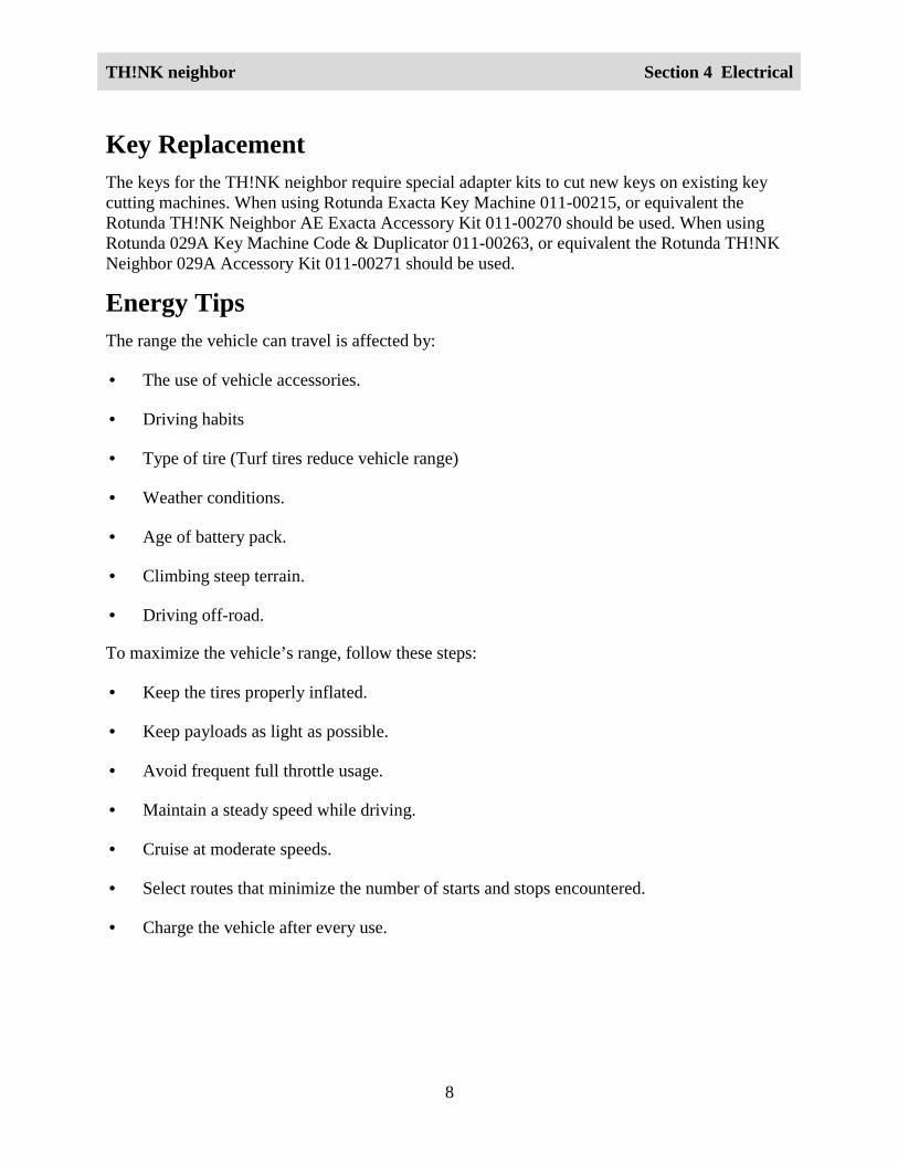
High Voltage Warning Label
LGI111_A
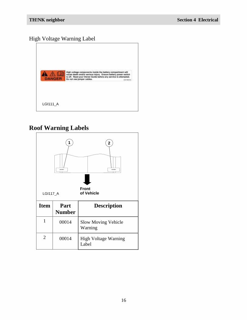
Roof Warning Labels
1 2
LGI117_AFrontof Vehicle
Item PartNumber
Description
1 00014 Slow Moving VehicleWarning
2 00014 High Voltage WarningLabel
TH!NK neighbor Section 4 Electrical
17
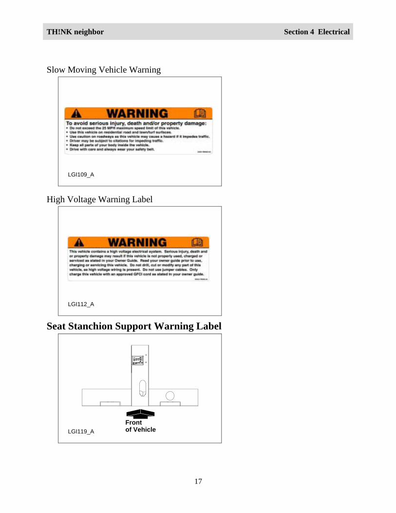
Slow Moving Vehicle Warning
LGI109_A
High Voltage Warning Label
LGI112_A
Seat Stanchion Support Warning Label
LGI119_A
Frontof Vehicle

TH!NK neighbor Section 4 Electrical
18
Service Disconnect Switch Label
LGI106_A
Service Disconnect Switch LabelThe service disconnect switch label is located directly under the driver seat on the seat stanchionH-support.
Instrument Panel Charge Warning Label
LGI133_AFrontof Vehicle
TH!NK neighbor Section 4 Electrical
19
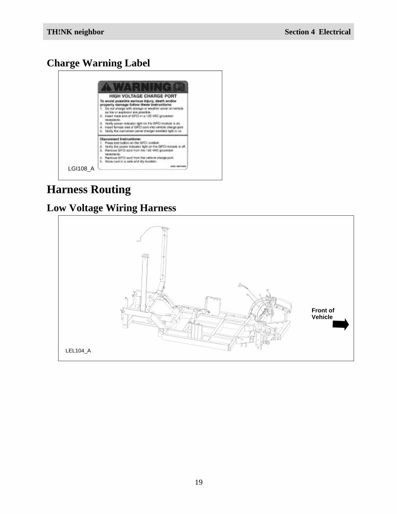
Charge Warning Label
LGI108_A
Harness RoutingLow Voltage Wiring Harness
LEL104_A
Front ofVehicle

TH!NK neighbor Section 4 Electrical
20
High Voltage Wiring HarnessesThe service disconnect switch location was modified mid year. Refer to the following.
1
4
2
3
4
5
6
LEL120_A
Front of Vehicle
7
8
8
Item Part Number Description1 14401 Low current high voltage wiring harness
2 14401 Motor controller harness
3 14401 High current high voltage wiring harness
4 14401 Battery interconnect harnesses

TH!NK neighbor Section 4 Electrical
21
Item Part Number Description5 14401 Mega-fuse and wiring harness assembly
6 14401 Power point wiring – Optional
7 14401 72V harness
8 -- Service disconnect switch
LEL105_A
Front ofVehicle
Battery ChargingBattery charging uses 120 volt AC 15A service. The GFCI (ground fault circuit interrupt) chargecord supplied with the vehicle plugs directly into the charge inlet located to the left of thesteering column on the front kick-up. Approximately 8-10 hours are needed to replenish a 20%(one bar showing) charged battery pack. Charge the vehicle whenever the state of charge is lessthan 80% (four bars showing), to maximize the travel range and prolong the battery life.
The battery charger receives 120 volt AC power from an external standard grounded 3-prong15A outlet and converts it to DC energy. The battery charger only operates when a GFCI chargercord is plugged into your vehicle. If the battery charger detects AC current (from the GFCIcharger cord), the vehicle cannot be started or driven.
WARNING!
THERE ARE GASES AROUND THE BATTERIES THAT CAN EXPLODE IFEXPOSED TO FLAMES, SPARKS, OR LIT CIGARETTES. THE AMOUNT OF GAS IS

TH!NK neighbor Section 4 Electrical
22
INCREASED DURING BATTERY CHARGING. AN EXPLOSION COULD RESULT INPERSONAL INJURY OR VEHICLE DAMAGE.
WARNING!
BATTERIES CONTAIN SULFURIC ACID, WHICH CAN BURN SKIN, EYES, ANDCLOTHING, IF CONTACTED.
TH!NK neighbor Section 4 Electrical
23
WARNING!
DO NOT CHARGE THE BATTERIES WITH THE WEATHER ENCLOSURE CLOSEDOR THE VEHICLE COVER IN PLACE. A BUILD UP OF HYDROGEN GAS CANRESULT WHICH CAN EXPLODE. THE CHARGING AREA SHOULD BE WELLVENTILATED.
CAUTION:
If the vehicle is allowed to sit in conditions of -6°°°°C (20°°°°F) or less with a state of charge of20% (one bar showing on gauge) or less, the batteries could freeze. Allowing the batteriesto freeze may cause permanent damage to the batteries and permanently reduce theircapacity. In cold conditions, place the vehicle in an area greater than 0°°°°C (32°°°°F) and allowit to warm up before charging. Never charge the vehicle if the batteries may be frozen.Allow the batteries to warm above 0°°°°C (32°°°°F) first, then charge.
CAUTION:
Do not park and leave the vehicle with discharged batteries. The batteries could dischargeto the point where damage could occur and the battery charger will not charge.
CAUTION:
If the battery pack is fully charged, the Regenerative Braking System (RBS) will not beenabled because the battery pack cannot accept the additional current. The contactor isdesigned to open if the battery pack voltage exceeds 80V. Avoid driving situations whereyou will be driving down steep grades with a fully charged battery pack or the drive systemand RBS will shut down. The standard braking system is not affected but speeds mayexceed 25 mph (40 km/h). If this should occur, apply brakes to reduce and maintain speedsbelow 25 mph (40 km/h).
Diagnosis and TestingDiagnostic Trouble Code InformationDescription and OperationThe instrument cluster gauge has the ability to detect and display diagnostic trouble codes(DTCs). The DTCs are of great value to the service technician in finding and repairing vehicleconcerns. The instrument cluster gauge stores the 20 most recent DTCs in memory. A completelist of DTCs is provided below.
When retrieving DTCs, record each of the DTCs displayed. Upon completion of the diagnosisand repair required for each DTC, clear the DTCs from the instrument cluster gauge. Refer to

TH!NK neighbor Section 4 Electrical
24
Retrieving and Clearing DTCs. Once the DTCs are cleared, operate the system and recheck forDTCs to verify the repair.
Retrieving and Clearing DTCsTo retrieve DTCs, set the park brake and perform the following:
1. While pressing the Select/Reset button, place the drive mode selector switch in the Driveposition.
2. Release the Select/Reset button within 5 seconds. The battery state of charge indicator andthe most recent DTC will be displayed.
3. Press and release the Select/Reset button to scroll through the DTCs. The most recent DTC isdisplayed first followed by the next most recent DTCs.
4. To clear DTCs, press and hold the Select/Reset button for more than 3 seconds.
5. To exit Retrieving and Clearing DTCs, place the drive mode selector switch in the OFFposition and either press the Select/Reset button or wait 10 seconds.
The DTC(s) and the odometer reading at which each DTC was set, along with the servicerequired (wrench) indicator, are the only items displayed when the instrument cluster gauge is inRetrieving and Clearing DTCs mode.
Diagnostic Trouble Code (DTC) Chart
DTC Description Reference05 Accelerator potentiometer switch fails to close. REFER to Accelerator
Potentiometer.
06 Accelerator potentiometer pedal is pressed withno direction signal given to motor controller.
REFER to AcceleratorPotentiometer.
08 Accelerator potentiometer input voltage to themotor controller is greater than 1.25V on power-up after initial drive mode selector switchclosure.
REFER to AcceleratorPotentiometer.
09 Both the forward and reverse direction switchesare closed at the same time.
REFER to InstrumentCluster Gauge.
11 Accelerator potentiometer switch closed onpower up after initial drive mode selector switchclosure.
REFER to AcceleratorPotentiometer.

TH!NK neighbor Section 4 Electrical
25
DTC Description Reference15 Battery voltage is less than 68.3 volts at initial
drive mode selector switch closure.REFER to Battery.
16 Battery voltage is greater than 86 volts at initialdrive mode selector switch closure.
REFER to Battery.
21 Accelerator voltage is too high. REFER to Motor andMotor Controller.
23 Motor field current is high on start-up in thereverse direction.
REFER to Motor andMotor Controller.
24 Motor field current is high on start-up in theforward direction.
REFER to Motor andMotor Controller.
27 12V bus is too low. REFER to Motor andMotor Controller.
41 Open thermal protector (TP) or transistor over-temperature.
REFER to Motor andMotor Controller.
42 Motor armature offset voltage too high. REFER to Motor andMotor Controller.
43 Motor armature offset voltage too low. REFER to Motor andMotor Controller.
44 Armature transistor did not turn off properly. REFER to Motor andMotor Controller.
45 Armature transistor did not turn on properly. REFER to Motor andMotor Controller.
46 “Look Ahead” test for A2 voltage less than 12%of battery voltage.
REFER to Motor andMotor Controller.
49 Motor field current is too low during the Runmode.
REFER to Motor andMotor Controller.
51 Capacitor voltage is low before the linecontactor closes.
REFER to Motor andMotor Controller.
57 Controller “motor current sensor” input too lowwhile running.
REFER to Motor andMotor Controller.

TH!NK neighbor Section 4 Electrical
26
DTC Description Reference66 The field current exceeds the current limit of the
field transistor.REFER to Motor andMotor Controller.
76 Capacitor 1C voltage too high duringregenerative braking.
REFER to Motor andMotor Controller.
77 Capacitor 1C voltage too high during motoring. REFER to Motor andMotor Controller.
90 Motor thermostat is open during controloperation.
REFER to Motor andMotor Controller.
Basic Troubleshooting InformationDescription and OperationBasic Troubleshooting Information is a series of troubleshooting flowcharts and pinpoint teststhat may be useful in diagnosing certain vehicle or system concerns. To diagnose any of thefollowing symptoms, refer to the corresponding troubleshooting flowchart and follow thediagnostic steps provided.

TH!NK neighbor Section 4 Electrical
27
Troubleshooting Flowcharts

TH!NK neighbor Section 4 Electrical
28

TH!NK neighbor Section 4 Electrical
29
TH!NK neighbor Section 4 Electrical
30
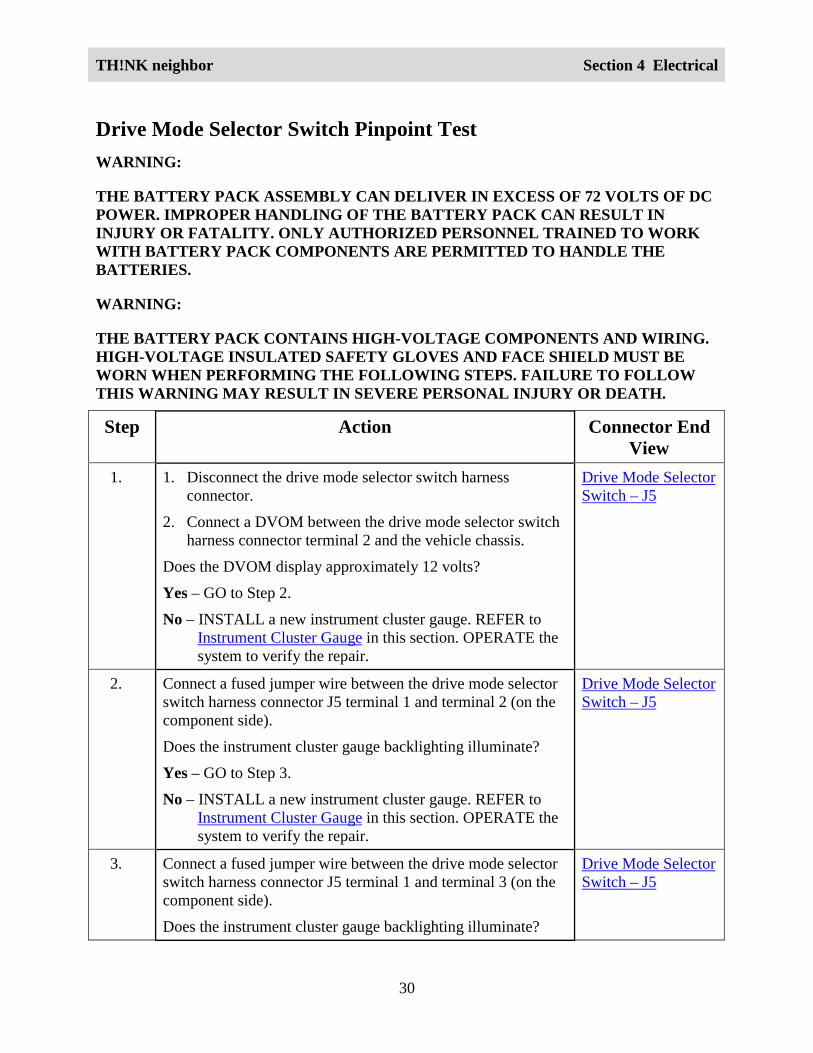
Drive Mode Selector Switch Pinpoint TestWARNING:
THE BATTERY PACK ASSEMBLY CAN DELIVER IN EXCESS OF 72 VOLTS OF DCPOWER. IMPROPER HANDLING OF THE BATTERY PACK CAN RESULT ININJURY OR FATALITY. ONLY AUTHORIZED PERSONNEL TRAINED TO WORKWITH BATTERY PACK COMPONENTS ARE PERMITTED TO HANDLE THEBATTERIES.
WARNING:
THE BATTERY PACK CONTAINS HIGH-VOLTAGE COMPONENTS AND WIRING.HIGH-VOLTAGE INSULATED SAFETY GLOVES AND FACE SHIELD MUST BEWORN WHEN PERFORMING THE FOLLOWING STEPS. FAILURE TO FOLLOWTHIS WARNING MAY RESULT IN SEVERE PERSONAL INJURY OR DEATH.
Step Action Connector EndView
1. 1. Disconnect the drive mode selector switch harnessconnector.
2. Connect a DVOM between the drive mode selector switchharness connector terminal 2 and the vehicle chassis.
Does the DVOM display approximately 12 volts?
Yes – GO to Step 2.
No – INSTALL a new instrument cluster gauge. REFER toInstrument Cluster Gauge in this section. OPERATE thesystem to verify the repair.
Drive Mode SelectorSwitch – J5
2. Connect a fused jumper wire between the drive mode selectorswitch harness connector J5 terminal 1 and terminal 2 (on thecomponent side).
Does the instrument cluster gauge backlighting illuminate?
Yes – GO to Step 3.
No – INSTALL a new instrument cluster gauge. REFER toInstrument Cluster Gauge in this section. OPERATE thesystem to verify the repair.
Drive Mode SelectorSwitch – J5
3. Connect a fused jumper wire between the drive mode selectorswitch harness connector J5 terminal 1 and terminal 3 (on thecomponent side).
Does the instrument cluster gauge backlighting illuminate?
Drive Mode SelectorSwitch – J5

TH!NK neighbor Section 4 Electrical
31
Step Action Connector EndView
Yes – GO to Step 4.
No – INSTALL a new instrument cluster gauge. REFER toInstrument Cluster Gauge in this section. OPERATE thesystem to verify the repair.
4. Connect a fused jumper wire between the drive mode selectorswitch harness connector J5 terminal 1 and terminal 4 (on thecomponent side).
Does the instrument cluster gauge backlighting illuminate?
Yes – INSTALL a new drive mode selector switch. REFER toDrive Mode Selector Switch in this section. OPERATEthe system to verify the repair.
No – INSTALL a new instrument cluster gauge. REFER toInstrument Cluster Gauge in this section. OPERATE thesystem to verify the repair.
Drive Mode SelectorSwitch – J5
Charge Icon Falsely Activated Pinpoint TestStep Action Connector End
View1. 1. Make sure the GFCI charger cord is not connected to the
vehicle.
2. Check the 30A charger fuse.
Is the fuse OK?
Yes – GO to Step 2.
No – INSTALL a new fuse. OPERATE the system to verifythe repair.
2. Check the fuse cap.
Is the fuse cap OK?
Yes – GO to Step 3.
No – INSTALL a new fuse cap. OPERATE the system toverify the repair.
3. Check charger harness connector and instrument cluster gaugeharness connectors for partially seated terminals, connectors

TH!NK neighbor Section 4 Electrical
32
Step Action Connector EndView
not mating properly and for dirt, moisture or corrosion.
Are the charger and instrument cluster gauge harnessconnectors OK?
Yes – INSTALL a new charger. REFER to Charger in thissection. OPERATE the system to verify the repair.
No – REPAIR the harness connector(s) as necessary.OPERATE the system to verify the repair.
Contactor Pinpoint TestStep Action Connector End
View1. Check the battery pack voltage
Is the battery pack voltage at least 68.3 volts?
Yes – GO to Step 2.
No – CHARGE the vehicle battery pack and retest. If thevoltage is still below 68.3 volts, REFER to Battery in thissection for further diagnosis.
2. 1. Turn the drive mode selector switch to the Reverse, Turf orDrive position.
2. Check the instrument cluster gauge.
Is the instrument cluster gauge charge icon activated?
Yes – REFER to the Charge Icon Falsely Activated PinpointTest.
No – GO to Step 3.
3. 1. Turn the drive mode selector switch to the off position.
2. Disconnect the motor controller harness connector.
3. Turn the drive mode selector switch to the Reverse, Turf orDrive position.
4. Connect a DVOM between motor controller harness
Motor Controller
TH!NK neighbor Section 4 Electrical
33
Step Action Connector EndView
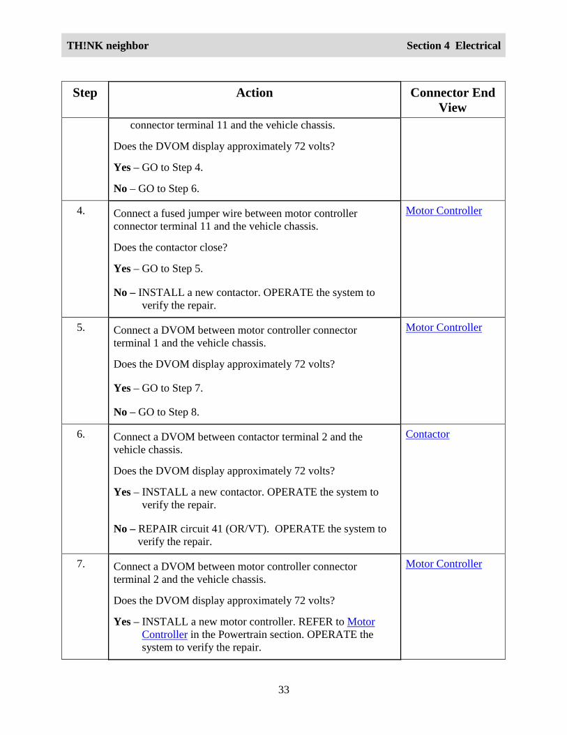
connector terminal 11 and the vehicle chassis.
Does the DVOM display approximately 72 volts?
Yes – GO to Step 4.
No – GO to Step 6.
4. Connect a fused jumper wire between motor controllerconnector terminal 11 and the vehicle chassis.
Does the contactor close?
Yes – GO to Step 5.
No – INSTALL a new contactor. OPERATE the system toverify the repair.
Motor Controller
5. Connect a DVOM between motor controller connectorterminal 1 and the vehicle chassis.
Does the DVOM display approximately 72 volts?
Yes – GO to Step 7.
No – GO to Step 8.
Motor Controller
6. Connect a DVOM between contactor terminal 2 and thevehicle chassis.
Does the DVOM display approximately 72 volts?
Yes – INSTALL a new contactor. OPERATE the system toverify the repair.
No – REPAIR circuit 41 (OR/VT). OPERATE the system toverify the repair.
Contactor
7. Connect a DVOM between motor controller connectorterminal 2 and the vehicle chassis.
Does the DVOM display approximately 72 volts?
Yes – INSTALL a new motor controller. REFER to MotorController in the Powertrain section. OPERATE thesystem to verify the repair.
Motor Controller

TH!NK neighbor Section 4 Electrical
34
Step Action Connector EndView
No – GO to Step 9.
8. 1. Disconnect the instrument cluster gauge connector J7A.
2. Connect a DVOM between the contactor connectorterminal 2 and the instrument cluster gauge connector J7Aterminal 7.
Does continuity exist?
Yes – INSTALL a new instrument cluster gauge. REFER toInstrument Cluster Gauge in this section. OPERATE thesystem to verify the repair.
No – REPAIR circuit 41 (OG/VT) between the contactor andthe instrument cluster gauge. OPERATE the system toverify the repair.
Instrument ClusterGauge—J7A
Contactor
Accelerator Potentiometer Pinpoint TestWARNING:
THE BATTERY PACK ASSEMBLY CAN DELIVER IN EXCESS OF 72 VOLTS OF DCPOWER. IMPROPER HANDLING OF THE BATTERY PACK CAN RESULT ININJURY OR FATALITY. ONLY AUTHORIZED PERSONNEL TRAINED TO WORKWITH BATTERY PACK COMPONENTS ARE PERMITTED TO HANDLE THEBATTERIES.
WARNING:
THE BATTERY PACK CONTAINS HIGH-VOLTAGE COMPONENTS AND WIRING.HIGH-VOLTAGE INSULATED SAFETY GLOVES AND FACE SHIELD MUST BEWORN WHEN PERFORMING THE FOLLOWING STEPS. FAILURE TO FOLLOWTHIS WARNING MAY RESULT IN SEVERE PERSONAL INJURY OR DEATH.
Step Action Connector EndView
1. 1. Place the drive mode selector switch in the OFFposition.
2. Disconnect the motor controller harness connector.3. Place the drive mode selector switch in the Reverse,
Turf or Drive position.
Motor ControllerAcceleratorPotentiometer

TH!NK neighbor Section 4 Electrical
35
Step Action Connector EndView
4. Connect a DVOM between the motor controllerharness connector terminal 3 and the vehicle chassis.
Does the DVOM display greater than 10 volts with theaccelerator pedal pressed and approximately 0 volts withthe accelerator pedal released?Yes - GO to Step 2.No – INSTALL a new accelerator potentiometer. REFER
to Accelerator Potentiometer in the Powertrainsection. OPERATE the system to verify the repair.
2. 1. Disconnect the motor controller harness connector andthe accelerator potentiometer harness connector.
2. Connect a DVOM between the motor controllerharness connector terminal 7 and the acceleratorpotentiometer harness connector terminal A.
3. Connect a DVOM between the motor controllerharness connector terminal 8 and the acceleratorpotentiometer harness connector terminal E.
4. Connect a DVOM between the motor controllerharness connector terminal 9 and the acceleratorpotentiometer harness connector terminal G.
5. Connect a DVOM between the motor controllerharness connector terminal 13 and the acceleratorpotentiometer harness connector terminal J
Does continuity exist?Yes – GO to Step 3.No – INSTALL a new 72 volt harness. REFER to Wiring
Harnesses in this section. OPERATE the system toverify the repair.
Motor ControllerAcceleratorPotentiometer
3. 1. Reconnect the accelerator potentiometer harnessconnector.
2 Connect a DVOM between the motor controllerharness connector terminal 7 and terminal 8.
Does the DVOM display between 1.9k and 3.9k ohms withthe accelerator potentiometer pedal raised and between3.7k and 5.7k ohms with the accelerator potentiometerpedal pressed?Yes – GO to Step 4.No – INSTALL a new accelerator potentiometer. REFER
Motor ControllerAcceleratorPotentiometer

TH!NK neighbor Section 4 Electrical
36
Step Action Connector EndView
to Accelerator Potentiometer in the Powertrainsection. OPERATE the system to verify the repair.
4. Connect a DVOM between the motor controller harnessconnector terminal 8 and terminal 13.Does the DVOM display between 3.7k and 5.7k ohms withthe accelerator potentiometer pedal raised and between1.9k and 3.9k ohms with the accelerator potentiometerpedal pressed?Yes – GO to Step 5.No – INSTALL a new accelerator potentiometer. REFER
to Accelerator Potentiometer in the Powertrainsection. OPERATE the system to verify the repair.
Motor Controller
5. Connect a DVOM between the motor controller harnessconnector terminal 8 and terminal 9.Does the DVOM display less than 5k ohms?Yes – INSTALL a new motor controller. REFER to Motor
Controller in the Powertrain section. OPERATE thesystem to verify the repair.
No – INSTALL a new accelerator potentiometer. REFERto Accelerator Potentiometer in the Powertrainsection. OPERATE the system to verify the repair.
Motor Controller
Charger Pinpoint TestWARNING:
THE BATTERY PACK ASSEMBLY CAN DELIVER IN EXCESS OF 72 VOLTS OF DCPOWER. IMPROPER HANDLING OF THE BATTERY PACK CAN RESULT ININJURY OR FATALITY. ONLY AUTHORIZED PERSONNEL TRAINED TO WORKWITH BATTERY PACK COMPONENTS ARE PERMITTED TO HANDLE THEBATTERIES.
WARNING:
THE BATTERY PACK CONTAINS HIGH-VOLTAGE COMPONENTS AND WIRING.HIGH-VOLTAGE INSULATED SAFETY GLOVES AND FACE SHIELD MUST BEWORN WHEN PERFORMING THE FOLLOWING STEPS. FAILURE TO FOLLOWTHIS WARNING MAY RESULT IN SEVERE PERSONAL INJURY OR DEATH.

TH!NK neighbor Section 4 Electrical
37
Step Action Connector EndView
1. 1. Disconnect the charger harness connector.
2. Connect a DVOM between the charger harness connectorterminal 1 and terminal 2.
Does the DVOM display approximately 72 volts?
Yes – GO to Step 2.
No – GO to Step 4.
Charger
2. 1. Reconnect the charger connector.
2. Connect the GFCI charger cord to the charger.
3. Verify charger operation by listening for a buzz noise andfeeling for a slight vibration from the charger.
Does the charger operate?
Yes – GO to Step 3.
No – GO to Step 7.
3. With the GFCI cord connected to the charger, connect aDVOM between the battery pack positive and battery packnegative.
Does the voltage increase after two minutes?
Yes – The system is OK.
No – TEST the batteries. REFER to Battery Test in thissection. If all batteries are OK, INSTALL a newcharger. REFER to Charger in this section. OPERATEthe system to verify the repair.
4. Connect a DVOM between the battery pack positive andbattery pack negative.
Does the DVOM display approximately 72 volts?
Yes – GO to Step 5.
No – TEST the batteries. REFER to Battery Test in thissection.
5. Connect a DVOM between the charger harness connectorterminal 2 and the battery pack negative.
Does continuity exist?
Yes – GO to Step 6.
Charger

TH!NK neighbor Section 4 Electrical
38
Step Action Connector EndView
No – INSTALL a new 72 volt harness. REFER to WiringHarnesses in this section. OPERATE the system toverify the repair.
6. 1. Perform the Power Shutdown Procedure. Refer to PowerShutdown Procedure in this section.
2. Connect a DVOM between the charger harness connectorterminal 1 and the battery pack positive.
Does continuity exist?
Yes – The system is OK.
No – INSTALL a new 72 volt harness. REFER to WiringHarnesses in this section. OPERATE the system toverify the repair.
Charger
7. 1. Connect a known good GFCI cord to the charger.
2. Verify charger operation by listening for a buzz noise andfeeling for a slight vibration from the charger.
Does the charger operate?
Yes – INSTALL a new GFCI cord. OPERATE the system toverify the repair.
No – INSTALL a new charger. REFER to Charger in thissection. OPERATE the system to verify the repair.

TH!NK neighbor Section 4 Electrical
39
Power DistributionCircuit Schematic

TH!NK neighbor Section 4 Electrical
40

TH!NK neighbor Section 4 Electrical
41

TH!NK neighbor Section 4 Electrical
42

TH!NK neighbor Section 4 Electrical
43

TH!NK neighbor Section 4 Electrical
44
Ground DistributionCircuit Schematic – With Heater/Defogger

TH!NK neighbor Section 4 Electrical
45
Without Heater/Defogger

TH!NK neighbor Section 4 Electrical
46

TH!NK neighbor Section 4 Electrical
47
Electrical Leakage DetectionCircuit Description and OperationThe electrical leakage detection circuit measures current flow from the battery pack to thevehicle frame. The battery pack is electrically isolated from the vehicle frame. There are foursystem components that ground to the frame: headlamps, chassis connector, wiper motor and thepark brake switch. The chassis connector circuit is between the instrument cluster gauge and aneyelet that is connected to the frame on the opposite side of the DC/DC converter 1 (standard).An OP AMP inside the instrument cluster gauge converts voltage to amperage from any placewhere leakage is detected. Any current above 0.1mA will set the electrical leakage indicator.Any part of the 72 volt harness has the potential for leakage detection. The 12 volt harness hasthe potential for leakage detection at the accelerator potentiometer and the motortachometer/speed sensor. Vehicles equipped with the optional power point will have a DC/DCconverter 2 (optional). The DC/DC converter 2 (optional) also has the potential for leakagedetection.
The following components and harnesses are to be checked for electrical leakage in thisprocedure:
• Contactor coil
• Instrument cluster gauge
• Motor controller
• DC/DC converter 1 (standard)
• DC/DC converter 2 (optional)
• Motor
• Motor tachometer/speed sensor
• Accelerator potentiometer
• Charger
• 72 volt harness
• Batteries

TH!NK neighbor Section 4 Electrical
48
Circuit Schematic

TH!NK neighbor Section 4 Electrical
49
Required ToolsHigh Voltage Insulated Gloves 100-F036 or equivalent
Face Shield 100-F035 or equivalent
Guidelines to diagnose electrical leakage:
1. Service disconnect switch must be in the ON position to observe the electrical leakageindicator located on the face of the instrument cluster gauge.
2. Before disconnecting any component, you must first place the service disconnect switch inthe OFF position.
3. Check all connectors and related wiring for partially seated terminals, connectors not matingproperly and for dirt, moisture or corrosion. For proper contact, terminal(s) must be free ofall foreign material. Wait at least 2 minutes after all debris has been cleared so that theinstrument cluster gauge has enough time to detect leakage.
4. Make sure the vehicle is thoroughly dry before attempting electrical leakage diagnosis.Electrical leakage may be detected if certain electrical connectors are exposed to moisturedue to rain or washing of the vehicle. This will cause the electrical leakage indicator in theinstrument cluster gauge to be set.
Electrical Leakage DiagnosisWARNING:
THE BATTERY PACK ASSEMBLY CAN DELIVER IN EXCESS OF 72 VOLTS OF DCPOWER. IMPROPER HANDLING OF THE BATTERY PACK CAN RESULT ININJURY OR FATALITY. ONLY AUTHORIZED PERSONNEL TRAINED TO WORKWITH BATTERY PACK COMPONENTS ARE PERMITTED TO HANDLE THEBATTERIES.
WARNING:
THE BATTERY PACK CONTAINS HIGH-VOLTAGE COMPONENTS AND WIRING.HIGH-VOLTAGE INSULATED SAFETY GLOVES AND FACE SHIELD MUST BEWORN WHEN PERFORMING THE FOLLOWING STEPS. FAILURE TO FOLLOWTHIS WARNING MAY RESULT IN SEVERE PERSONAL INJURY OR DEATH.

TH!NK neighbor Section 4 Electrical
50
Step Action Connector EndView
1 Did you read the Circuit Description and Operation?
Yes - GO to Step 2.
No - REFER to Circuit Description and Operation in thissection.
2 1. Place the service disconnect switch in the OFFposition.
2. Disconnect the chassis connector.
3. Place the service disconnect switch in the ONposition.
4. Set the park brake.
5. Place the drive mode selector switch in theReverse, Turf or Drive mode and wait 10 seconds.
6. Observe the instrument cluster gauge.
Does the electrical leakage indicator display?
Yes – INSTALL a new instrument cluster gauge. REFERto Instrument Cluster Gauge in this section. OPERATE thesystem to verify the repair.
No – RECONNECT the chassis connector. GO to Step 3.
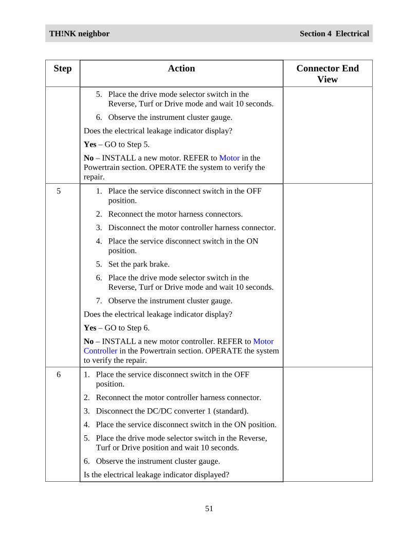
3 Drive the vehicle while observing the instrument clustergauge.
Does the electrical leakage indicator display only afterheavy acceleration or high motor load?
Yes – INSTALL a new motor. REFER to Motor in thePowertrain section. OPERATE the system to verify therepair.
No – GO to Step 4.
4 1. Place the service disconnect switch in the OFFposition.
2. Disconnect the motor harness connectors.
3. Place the service disconnect switch in the ONposition.
4. Set the park brake.
TH!NK neighbor Section 4 Electrical
51
Step Action Connector EndView
5. Place the drive mode selector switch in theReverse, Turf or Drive mode and wait 10 seconds.
6. Observe the instrument cluster gauge.
Does the electrical leakage indicator display?
Yes – GO to Step 5.
No – INSTALL a new motor. REFER to Motor in thePowertrain section. OPERATE the system to verify therepair.
5 1. Place the service disconnect switch in the OFFposition.
2. Reconnect the motor harness connectors.
3. Disconnect the motor controller harness connector.
4. Place the service disconnect switch in the ONposition.
5. Set the park brake.
6. Place the drive mode selector switch in theReverse, Turf or Drive mode and wait 10 seconds.
7. Observe the instrument cluster gauge.
Does the electrical leakage indicator display?
Yes – GO to Step 6.
No – INSTALL a new motor controller. REFER to MotorController in the Powertrain section. OPERATE the systemto verify the repair.
6 1. Place the service disconnect switch in the OFFposition.
2. Reconnect the motor controller harness connector.
3. Disconnect the DC/DC converter 1 (standard).
4. Place the service disconnect switch in the ON position.
5. Place the drive mode selector switch in the Reverse,Turf or Drive position and wait 10 seconds.
6. Observe the instrument cluster gauge.
Is the electrical leakage indicator displayed?

TH!NK neighbor Section 4 Electrical
52
Step Action Connector EndView
Yes – If vehicle is equipped with DC/DC converter 2(optional), GO to Step 7.
If the vehicle is not equipped with DC/DC converter 2(optional), GO to Step 8.
No – INSTALL a new DC/DC converter 1 (standard).REFER to DC/DC Converter 1 (Standard) in thissection. OPERATE the system to verify the repair.
7 1. Place the service disconnect switch in the OFFposition.
2. Reconnect the DC/DC converter 1 (standard)harness connector.
3. Disconnect the DC/DC converter 2 (optional).
4. Place the service disconnect switch in the ONposition.
5. Place the drive mode selector switch in theReverse, Turf or Drive position and wait 10seconds.
6. Observe the instrument cluster gauge.
Is the electrical leakage indicator displayed?
Yes - GO to Step 8.
No - INSTALL a new DC/DC converter 2 (optional).REFER to DC/DC Converter (Optional) in thissection. OPERATE the system to verify the repair.
8 1. Place the service disconnect switch in the OFFposition.
2. Reconnect the DC/DC converter 2 (optional) (ifequipped) and the DC/DC converter 1 (standard)harness connectors.
3. Disconnect the charger harness connector.
4. Place the service disconnect switch in the ONposition.
5. Place the drive mode selector switch in theReverse, Turf or Drive position and wait 10seconds.

TH!NK neighbor Section 4 Electrical
53
Step Action Connector EndView
6. Observe the instrument cluster gauge.
Is the electrical leakage indicator displayed?
Yes - GO to Step 9.
No - INSTALL a new charger. REFER to Charger in thissection. OPERATE the system to verify the repair.
9 1. Place the service disconnect switch in the OFFposition.
2. Reconnect the charger harness connector.
3. Disconnect the accelerator potentiometer harnessconnector.
4. Place the service disconnect switch in the ONposition.
5. Place the drive mode selector switch in theReverse, Turf or Drive position and wait 10seconds.
6. Observe the instrument cluster gauge.
Is the electrical leakage indicator displayed?
Yes – GO to Step 10.
No – INSTALL a new accelerator potentiometer. REFERto Accelerator Potentiometer in the Powertrain section.OPERATE the system to verify the repair.
10 1. Place the service disconnect switch in the OFFposition.
2. Reconnect the accelerator potentiometer harnessconnector.
3. Disconnect the motor tachometer/speed sensor harnessconnector.
4. Place the service disconnect switch in the ON position.
5. Place the drive mode selector switch in the Reverse,Turf or Drive position and wait 10 seconds.
6. Observe the instrument cluster gauge.
Is the electrical leakage indicator displayed?
Yes - GO to Step 11.

TH!NK neighbor Section 4 Electrical
54
Step Action Connector EndView
No - INSTALL a new motor tachometer/speed sensor.REFER to Motor Tachometer/Speed Sensor in thePowertrain section. OPERATE the system to verifythe repair.
11 1. Place the service disconnect switch in the OFFposition.
2. Reconnect the motor tachometer/speed sensor harnessconnector.
3. Disconnect the contactor coil harness connectors.
4. Place the service disconnect switch in the ON position.
5. Place the drive mode selector switch in the Reverse,Turf or Drive position and wait 10 seconds.
6. Observe the instrument cluster gauge.
Is the electrical leakage indicator displayed?
Yes – GO to Step 12.
No - INSTALL a new contactor coil. REFER to Contactorin this section. OPERATE the system to verify therepair.
12 1. Place the service disconnect switch in the OFFposition.
2. Reconnect the motor tachometer/speed sensorharness connector.
3. Clean battery cases and battery compartment tomake sure there is no dirt, moisture or corrosionbuildup that could create an electrical leak path.
4. Place the service disconnect switch in the ONposition.
5. Place the drive mode selector switch in theReverse, Turf or Drive position and wait 10seconds.
6. Observe the instrument cluster gauge.
Is the electrical leakage indicator displayed?
Yes – INSTALL a new 72 volt harness. REFER to WiringHarnesses in this section. OPERATE the system to verify

TH!NK neighbor Section 4 Electrical
55
Step Action Connector EndView
the repair.
No – GO to Step 13.
13 Connect the positive lead of a DVOM to the positiveterminal of the first battery (from the negative end of thebattery pack). Connect the negative lead of the DVOM tothe vehicle chassis.
Does the DVOM display negative voltage?
Yes – REMOVE and CLEAN the battery with a bakingsoda solution. REINSTALL the battery and RETEST toverify the repair.
No – MOVE the positive lead of the DVOM to the positiveterminal of the next battery of the battery pack. CHECKeach battery until a negative voltage is displayed on theDVOM. REMOVE and CLEAN the battery that displays anegative voltage. RETEST to verify the repair.
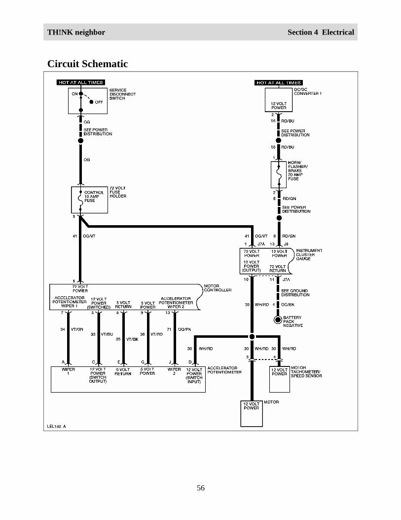
Accelerator PotentiometerCircuit Description and OperationWhen the contactor is turned on, the accelerator potentiometer receives 12 volts from theinstrument cluster gauge. When the accelerator potentiometer pedal is pressed, a 12 volt signal issent from the accelerator potentiometer to the motor controller. Two additional voltage signalsare also sent from the accelerator potentiometer to the motor controller. These additional signalswill vary depending on accelerator potentiometer pedal position. The motor controller uses thesesignals to control motor speed.
TH!NK neighbor Section 4 Electrical
56
Circuit Schematic

TH!NK neighbor Section 4 Electrical
57

TH!NK neighbor Section 4 Electrical
58
Required ToolsHigh Voltage Insulated Gloves 100-F036 or equivalent
Face Shield 100-F035 or equivalent
System CheckFunctional components in the accelerator potentiometer system are:
• Service disconnect switch
• Control fuse
• Motor controller
• Instrument cluster gauge
• Accelerator potentiometer
• Motor tachometer/speed sensor
Guidelines to diagnose the accelerator potentiometer system:
1. Verify the concern.
2. Check the fuse(s).
3. Check all connectors and related wiring for partially seated terminals, connectors not matingproperly and for dirt, moisture or corrosion. For proper contact, terminal(s) must be free ofall foreign material.
4. Verify service disconnect switch is in ON position.
5. Check for any diagnostic trouble codes. Refer to Retrieving and Clearing DTCs.
If the concern still exists, refer to the following table:

TH!NK neighbor Section 4 Electrical
59
Symptom ChartSymptom Possible Causes Action
Vehicle speed does notchange when acceleratorpotentiometer positionchanges.
• Accelerator potentiometer
• Connectors and relatedwiring
GO to AcceleratorPotentiometer Inoperative.
Accelerator Potentiometer InoperativeWARNING:
THE BATTERY PACK ASSEMBLY CAN DELIVER IN EXCESS OF 72 VOLTS OF DCPOWER. IMPROPER HANDLING OF THE BATTERY PACK CAN RESULT ININJURY OR FATALITY. ONLY AUTHORIZED PERSONNEL TRAINED TO WORKWITH BATTERY PACK COMPONENTS ARE PERMITTED TO HANDLE THEBATTERIES.
WARNING:
THE BATTERY PACK CONTAINS HIGH-VOLTAGE COMPONENTS AND WIRING.HIGH-VOLTAGE INSULATED SAFETY GLOVES AND FACE SHIELD MUST BEWORN WHEN PERFORMING THE FOLLOWING STEPS. FAILURE TO FOLLOWTHIS WARNING MAY RESULT IN SEVERE PERSONAL INJURY OR DEATH.
Step Action Connector EndView
1. Did you read the Circuit Description and Operation?Yes - GO to Step 2.No - REFER to Circuit Description and Operation in thissection.
2. 1. Disconnect the motor controller harness connector and theaccelerator potentiometer harness connector.
2. Connect a DVOM between the motor controller harnessconnector terminal 7 and the accelerator potentiometerharness connector terminal A.
3. Connect a DVOM between the motor controller harnessconnector terminal 8 and the accelerator potentiometerharness connector terminal E.
4. Connect a DVOM between the motor controller harnessconnector terminal 9 and the accelerator potentiometerharness connector terminal G.
5. Connect a DVOM between the motor controller harness
Motor ControllerAcceleratorPotentiometer

TH!NK neighbor Section 4 Electrical
60
Step Action Connector EndView
connector terminal 13 and the accelerator potentiometerharness connector terminal J
Does continuity exist?Yes – GO to Step 3.No – INSTALL a new 72 volt harness. REFER to Wiring
Harnesses in this section. OPERATE the system toverify the repair.
3. 1. Reconnect the accelerator potentiometer harnessconnector.
2. Connect a DVOM between the motor controllerharness connector terminal 7 and terminal 8.
Does the DVOM display between 1.9k and 3.9k ohms withthe accelerator potentiometer pedal raised and between3.7k and 5.7k ohms with the accelerator potentiometerpedal pressed?Yes – GO to Step 4.No – INSTALL a new accelerator potentiometer. REFERto Accelerator Potentiometer in the Powertrain section.OPERATE the system to verify the repair.
Motor ControllerAcceleratorPotentiometer
4. Connect a DVOM between the motor controller harnessconnector terminal 8 and terminal 13.Does the DVOM display between 3.7k and 5.7k ohms withthe accelerator potentiometer pedal raised and between1.9k and 3.9k ohms with the accelerator potentiometerpedal pressed?Yes – GO to Step 5.No – INSTALL a new accelerator potentiometer. REFERto Accelerator Potentiometer in the Powertrain section.OPERATE the system to verify the repair.
Motor Controller
5. Connect a DVOM between the motor controller harnessconnector terminal 8 and terminal 9.Does the DVOM display less than 5k ohms?Yes – INSTALL a new motor controller. REFER to Motor
Controller in the Powertrain section. OPERATE thesystem to verify the repair.
No – INSTALL a new accelerator potentiometer. REFERto Accelerator Potentiometer in the Powertrain section.OPERATE the system to verify the repair.
Motor Controller
TH!NK neighbor Section 4 Electrical
61
DTC 05
Description:
Accelerator potentiometer switch fails to close.
Symptom:
Motor controller will not operate.
Possible cause(s):• Accelerator potentiometer
• Connectors and related wiring
WARNING:
THE BATTERY PACK ASSEMBLY CAN DELIVER IN EXCESS OF 72 VOLTS OF DCPOWER. IMPROPER HANDLING OF THE BATTERY PACK CAN RESULT ININJURY OR FATALITY. ONLY AUTHORIZED PERSONNEL TRAINED TO WORKWITH BATTERY PACK COMPONENTS ARE PERMITTED TO HANDLE THEBATTERIES.
WARNING:
THE BATTERY PACK CONTAINS HIGH-VOLTAGE COMPONENTS AND WIRING.HIGH-VOLTAGE INSULATED SAFETY GLOVES AND FACE SHIELD MUST BEWORN WHEN PERFORMING THE FOLLOWING STEPS. FAILURE TO FOLLOWTHIS WARNING MAY RESULT IN SEVERE PERSONAL INJURY OR DEATH.
Step Action Connector EndView
1 Did you read the Circuit Description and Operation?Yes - GO to Step 2.No - REFER to Circuit Description and Operation in thissection.
2 1. Disconnect the motor controller harness connector.2. Set the park brake.3. Place the drive mode selector switch in the Reverse,
Turf or Drive position.4. Connect a DVOM between the motor controller
harness connector terminal 3 and the vehicle chassis.Does the DVOM display approximately 12 volts with the
Motor Controller

TH!NK neighbor Section 4 Electrical
62
Step Action Connector EndView
accelerator potentiometer pedal pressed?Yes – INSTALL a new motor controller. REFER to Motor
Controller in the Powertrain section. OPERATE thesystem to verify the repair.
No – GO to Step 3.3 1. Disconnect the accelerator potentiometer harness
connector.2. Connect a DVOM between the accelerator
potentiometer harness connector terminal C andterminal D.
Does the DVOM display approximately 3.3k ohms withthe accelerator potentiometer pedal pressed?Yes – GO to Step 4.No – INSTALL a new accelerator potentiometer. REFERto Accelerator Potentiometer in the Powertrain section.OPERATE the system to verify the repair.
AcceleratorPotentiometer
4 Connect a DVOM between the accelerator potentiometerharness connector terminal D and the vehicle chassis.Does the DVOM display approximately 12 volts?Yes – INSTALL a new 72 volt harness. REFER to Wiring
Harnesses in this section. OPERATE the system toverify the repair.
No – GO to Step 5.
AcceleratorPotentiometer
5 Connect a DVOM between the instrument cluster gaugeharness connector J7A (back probe) terminal 10 and thevehicle chassis.Does the DVOM display approximately 12 volts?Yes – INSTALL a new 72 volt harness. REFER to Wiring
Harnesses in this section. OPERATE the system toverify the repair.
No – INSTALL a new instrument cluster gauge. REFER toInstrument Cluster Gauge in this section. OPERATE thesystem to verify the repair.
Instrument ClusterGauge – J7A

TH!NK neighbor Section 4 Electrical
63
DTC 06
Description:
Accelerator potentiometer pedal is pressed with no direction signal given to the controller.
Symptom:
Motor controller will not operate.
Possible cause(s):• Accelerator potentiometer
• Connectors and related wiring
• Instrument cluster gauge
WARNING:
THE BATTERY PACK ASSEMBLY CAN DELIVER IN EXCESS OF 72 VOLTS OF DCPOWER. IMPROPER HANDLING OF THE BATTERY PACK CAN RESULT ININJURY OR FATALITY. ONLY AUTHORIZED PERSONNEL TRAINED TO WORKWITH BATTERY PACK COMPONENTS ARE PERMITTED TO HANDLE THEBATTERIES.
WARNING:
THE BATTERY PACK CONTAINS HIGH-VOLTAGE COMPONENTS AND WIRING.HIGH-VOLTAGE INSULATED SAFETY GLOVES AND FACE SHIELD MUST BEWORN WHEN PERFORMING THE FOLLOWING STEPS. FAILURE TO FOLLOWTHIS WARNING MAY RESULT IN SEVERE PERSONAL INJURY OR DEATH.
Step Action Connector EndView
1 Did you perform the Diagnostic System Check?Yes - GO to Step 2.No - REFER to Diagnostic System Check in this section.
2 1. Set the park brake.2. Place the drive mode selector switch in the Reverse
position.3. Disconnect the motor controller harness connector.4. Connect a DVOM between the motor controller harness
connector terminal 5 and the vehicle chassis.
Motor Controller

TH!NK neighbor Section 4 Electrical
64
Step Action Connector EndView
Does the DVOM display approximately 12 volts?Yes - GO to Step 3.No – GO to Step 4.
3 1. Place the drive mode selector switch in the Driveposition.
2. Connect a DVOM between the motor controller harnessconnector terminal 6 and the vehicle chassis.
Does the DVOM display approximately 12 volts?
Yes - INSTALL a new motor controller. REFER to MotorController in the Powertrain section. OPERATEsystem to verify the repair.
No - GO to Step 5.
Motor Controller
4 1. Disconnect the instrument cluster gauge harnessconnector J7A.
2. Connect a DVOM between the instrument cluster gaugeharness connector J7A terminal 4 and the motorcontroller harness connector terminal 5.
Does continuity exist?Yes - INSTALL a new instrument cluster gauge. REFER to
Instrument Cluster Gauge in this section. OPERATEthe system to verify the repair.
No – INSTALL a new 72 volt harness. REFER to WiringHarnesses in this section. OPERATE the system toverify the repair.
Instrument ClusterGauge – J7AMotor Controller
5 Connect a DVOM between the instrument cluster gaugeharness connector J7A terminal 3 and the motor controllerharness connector terminal 6.Does continuity exist?Yes - INSTALL a new instrument cluster gauge. REFER to
Instrument Cluster Gauge in this section. OPERATEthe system to verify the repair.
No – INSTALL a new 72 volt harness. REFER to WiringHarnesses in this section. OPERATE the system toverify the repair.
Instrument ClusterGauge – J7AMotor Controller

TH!NK neighbor Section 4 Electrical
65
DTC 08
Description:
Accelerator potentiometer input voltage to the motor controller is greater than 1.25 volts onpower-up after initial drive mode selector switch closure.
Symptom:
Motor controller will not operate.
Possible cause(s):• Accelerator potentiometer
• Connectors and related wiring
• Motor controller
Step Action Connector EndView
1 Did you perform the Diagnostic System Check?
Yes - GO to Step 3.
No - REFER to Diagnostic System Check in this section.
2 1. Disconnect the motor controller harness connector.
2. Disconnect the accelerator potentiometer harnessconnector.
3. Connect a DVOM between the motor controller harnessconnector terminal 7 and each of the other terminals ofthe motor controller harness connector.
Does continuity exist between circuit 34 and any othercircuit in the motor controller harness connector?
Yes - INSTALL a new 72 volt harness. REFER to WiringHarnesses in this section. OPERATE the system toverify the repair.
No – GO to Step 3.
Motor Controller
AcceleratorPotentiometer
3 Connect a DVOM between the motor controller terminal 7and the vehicle chassis.
Does the DVOM display greater than approximately 1.25
Motor Controller

TH!NK neighbor Section 4 Electrical
66
Step Action Connector EndView
volts?
Yes - INSTALL a new motor controller. REFER to MotorController in the Powertrain section. OPERATE thesystem to verify the repair.
No – INSTALL a new accelerator potentiometer. REFERto Accelerator Potentiometer in the Powertrainsection. OPERATE the system to verify the repair.
DTC 11
Description:
Accelerator potentiometer switch closed on power-up after initial drive mode selector switchclosure.
Symptom:
Motor controller will not operate.
Possible cause(s):• Accelerator potentiometer
• Connectors and related wiring
• Motor controllerNote: Check all vehicle fuses before performing this diagnostic procedure.
WARNING:
THE BATTERY PACK ASSEMBLY CAN DELIVER IN EXCESS OF 72 VOLTS OF DCPOWER. IMPROPER HANDLING OF THE BATTERY PACK CAN RESULT ININJURY OR FATALITY. ONLY AUTHORIZED PERSONNEL TRAINED TO WORKWITH BATTERY PACK COMPONENTS ARE PERMITTED TO HANDLE THEBATTERIES.
WARNING:
THE BATTERY PACK CONTAINS HIGH-VOLTAGE COMPONENTS AND WIRING.HIGH-VOLTAGE INSULATED SAFETY GLOVES AND FACE SHIELD MUST BEWORN WHEN PERFORMING THE FOLLOWING STEPS. FAILURE TO FOLLOWTHIS WARNING MAY RESULT IN SEVERE PERSONAL INJURY OR DEATH.

TH!NK neighbor Section 4 Electrical
67
Step Action Connector EndView
1 Did you perform the Diagnostic System Check?Yes - GO to Step 2.No - Refer to Diagnostic System Check in this section.
2 1. Disconnect the motor controller harness connector.
2. Disconnect the accelerator potentiometer harnessconnector.
3. Connect a DVOM between the motor controllerharness connector terminal 7 and each of the otherterminals of the motor controller harness connector.
Does continuity exist between circuit 33 and any othercircuit in the motor controller harness connector?
Yes - INSTALL a new 72 volt harness. REFER toWiring Harnesses in this section. OPERATE thesystem to verify the repair.
No - GO to Step 3.
Motor ControllerAcceleratorPotentiometer
3 Connect a DVOM between the motor controller harnessconnector terminal 3 and the vehicle chassis.Does the DVOM display greater than approximately 7.2volts?Yes - INSTALL a new motor controller. REFER to
Motor Controller in the Powertrain section.OPERATE the system to verify the repair.
No – INSTALL a new accelerator potentiometer.REFER to Accelerator Potentiometer in thePowertrain section. OPERATE the system toverify the repair.
Motor Controller
BatteryCircuit Description and Operation72 volt power is supplied a pack by six 12 volt batteries connected in series. The battery pack isdivided into two banks of three batteries, which are connected by a 400 amp megafuse.

TH!NK neighbor Section 4 Electrical
68
Circuit Schematic

TH!NK neighbor Section 4 Electrical
69
Required ToolsHigh Voltage Insulated Gloves 100-F036 or equivalent
Face Shield 100-F035 or equivalent
System CheckFunctional components in the battery system are:
• Batteries
• 400 amp megafuse
• Contactor coil
Guidelines to diagnose the battery system:
1. Verify the concern.
2. Check the fuse(s).
3. Check all connectors and related wiring for partially seated terminals, connectors not matingproperly and for dirt, moisture or corrosion. For proper contact, terminal(s) must be free ofall foreign material.
4. Check for any diagnostic trouble codes. Refer to Retrieving and Clearing DTCs in thissection.
If the concern still exists, refer to the following table.
Symptom ChartSymptom Possible Causes Action
The vehicle does notoperate — no power
• Battery
• 400 amp megafuse
GO to Battery Test.
Selecting Battery TypeWhen the maintenance-free battery mode is selected, the battery water reminder indicator willnot be displayed on the instrument cluster gauge. If the flooded battery mode is selected, thebattery water reminder will be displayed under either of the following conditions:
• When the drive mode selector switch is turned to the Reverse, Turf or Drive position and theinstrument cluster gauge performs an indicator test.

TH!NK neighbor Section 4 Electrical
70
• When the vehicle has been driven at least 300 miles (483 km) since the last reset oractivation of the battery water reminder.
To toggle the battery type between flooded battery mode and maintenance-free battery mode,perform the following:
1. While pressing the Select/Reset button, place the drive mode selector switch in the Driveposition.
2. Release the Select/Reset button within 5 seconds.
3. Place the drive mode selector switch in the Reverse position.
4. Press and release the Select/Reset button to toggle between the flooded battery mode and themaintenance-free battery mode.
5. To exit Selecting Battery Type, place the drive mode selector switch in the OFF position andeither press the Select/Reset button or wait 10 seconds.
The battery water reminder indicator is the only indicator displayed when the instrument clustergauge is in Selecting Battery Type mode.
Battery TestWARNING:
THE BATTERY PACK ASSEMBLY CAN DELIVER IN EXCESS OF 72 VOLTS OF DCPOWER. IMPROPER HANDLING OF THE BATTERY PACK CAN RESULT ININJURY OR FATALITY. ONLY AUTHORIZED PERSONNEL TRAINED TO WORKWITH BATTERY PACK COMPONENTS ARE PERMITTED TO HANDLE THEBATTERIES.
WARNING:
THE BATTERY PACK CONTAINS HIGH-VOLTAGE COMPONENTS AND WIRING.HIGH-VOLTAGE INSULATED SAFETY GLOVES AND FACE SHIELD MUST BEWORN WHEN PERFORMING THE FOLLOWING STEPS. FAILURE TO FOLLOWTHIS WARNING MAY RESULT IN SEVERE PERSONAL INJURY OR DEATH.
The battery test is done by measuring individual battery voltages with a calibrated voltmeter.This test determines the general state of charge and battery condition quickly. Use the RotundaAlternator, Regulator Battery and Starter Tester (ARBST) 010-00725 or equivalent. Apply a 50amp load to each of the batteries for no more than 10 seconds. Read the voltage before removingthe load. A well-charged battery should maintain at least 12 volts. If the meter reads less thanapproximately 11.5 volts, the battery is not charged adequately, or it may be defective. Chargethe battery using a battery charger and perform the test again. When charging the individualbatteries, make sure the battery charger leads are clamped to the bases of the battery posts and

TH!NK neighbor Section 4 Electrical
71
not the threaded studs. If battery voltage is not within specification, replace the battery. Refer toBatteries in this section. Charge the new battery using a 12 volt battery charger and perform thetest again.
DTC 15
Description:
Battery voltage is less than 68.3 volts at initial drive mode selector switch closure.
Symptom:
Motor controller will not operate.
Possible cause(s):
Discharged or inoperative battery or batteries.
Note:
Check all vehicle fuses before performing this diagnostic procedure.
WARNING:
THE BATTERY PACK ASSEMBLY CAN DELIVER IN EXCESS OF 72 VOLTS OF DCPOWER. IMPROPER HANDLING OF THE BATTERY PACK CAN RESULT ININJURY OR FATALITY. ONLY AUTHORIZED PERSONNEL TRAINED TO WORKWITH BATTERY PACK COMPONENTS ARE PERMITTED TO HANDLE THEBATTERIES.
WARNING:
THE BATTERY PACK CONTAINS HIGH-VOLTAGE COMPONENTS AND WIRING.HIGH-VOLTAGE INSULATED SAFETY GLOVES AND FACE SHIELD MUST BEWORN WHEN PERFORMING THE FOLLOWING STEPS. FAILURE TO FOLLOWTHIS WARNING MAY RESULT IN SEVERE PERSONAL INJURY OR DEATH.
Step Action ConnectorEnd View
1 Did you perform the Diagnostic System Check?Yes – GO to Step 2.No - REFER to Diagnostic System Check in this section.
2 Connect a DVOM between the battery pack positive and thebattery pack negative.Is the voltage less than 68.3 volts?

TH!NK neighbor Section 4 Electrical
72
Step Action ConnectorEnd View
Yes – If the vehicle is equipped with flooded batteries, GO toStep 3.If the vehicle is equipped with maintenance-free batteries, GO toStep 4.No – The system is OK.
3 Inspect the batteries for the proper water level. Refer to BatteryFill Procedure in the General Information section.Is the water level OK?Yes - GO to Step 4.No - Fill the batteries to the correct level with de-ionized ordistilled water. GO to Step 4.
4 1. Fully charge each individual battery using a battery charger.
2. Connect a DVOM between the battery pack positive and thebattery pack negative.
Is the voltage less than 68.3 volts?Yes – REFER to Battery Test in this section.No – The system is OK.

TH!NK neighbor Section 4 Electrical
73
DTC 16
Description:
Battery voltage is greater than 86 volts at initial drive mode selector switch closure.
Symptom:
Motor controller will not operate.
Possible cause(s):
• GFCI charger cord is connected to the charger.
• Battery voltage too high.
WARNING:
THE BATTERY PACK ASSEMBLY CAN DELIVER IN EXCESS OF 72 VOLTS OF DCPOWER. IMPROPER HANDLING OF THE BATTERY PACK CAN RESULT ININJURY OR FATALITY. ONLY AUTHORIZED PERSONNEL TRAINED TO WORKWITH BATTERY PACK COMPONENTS ARE PERMITTED TO HANDLE THEBATTERIES.
WARNING:
THE BATTERY PACK CONTAINS HIGH-VOLTAGE COMPONENTS AND WIRING.HIGH-VOLTAGE INSULATED SAFETY GLOVES AND FACE SHIELD MUST BEWORN WHEN PERFORMING THE FOLLOWING STEPS. FAILURE TO FOLLOWTHIS WARNING MAY RESULT IN SEVERE PERSONAL INJURY OR DEATH.
Step Action ConnectorEnd View
1 Did you perform the Diagnostic System Check?Yes - GO to Step 2.No - REFER to Diagnostic System Check in this section.
2 Connect a DVOM between the battery pack positive and thebattery pack negative.Is the voltage greater than 86 volts?Yes – REFER to Battery Test, in this section, to check the
individual batteries for overcharge.No – The system is OK.
TH!NK neighbor Section 4 Electrical
74
ChargingCircuit Description and OperationThe battery charger receives 120-volt AC power from an external standard grounded 3-prongoutlet and converts it to DC power as required to charge the vehicle battery pack. After properlyconnecting the vehicle to the receptacle, the charger will initiate a four stage charging process.In the first stage, the battery pack is tested. If the battery pack passes, the charger determines theappropriate charging rate, depending upon the voltage of the battery pack, and charges thebattery pack. In the second and third stages, the voltage is regulated, and charging is completed.The battery pack is maintained at the full state of charge in the fourth stage. If the vehicle is leftconnected to the charger, the charger will automatically reinitiate a new charge cycle every 28days. The rate at which the battery pack charges will vary, depending on the type of batteriesinstalled. To ensure a fully charged battery pack, the vehicle should be charged continuouslyand uninterrupted for 14 hours. The instrument cluster gauge must be set for the type of batteriesthat are installed in the vehicle to prevent excessive charge time or damage to the batteries.Refer to Battery Type Reprogramming in this section. The battery charger should only beoperated with the supplied GFCI charger cord. If the battery charger detects current from theGFCI charger cord, it will send a signal to the instrument cluster gauge. The instrument clustergauge will then display the charging indicator and prevent the vehicle from being driven.
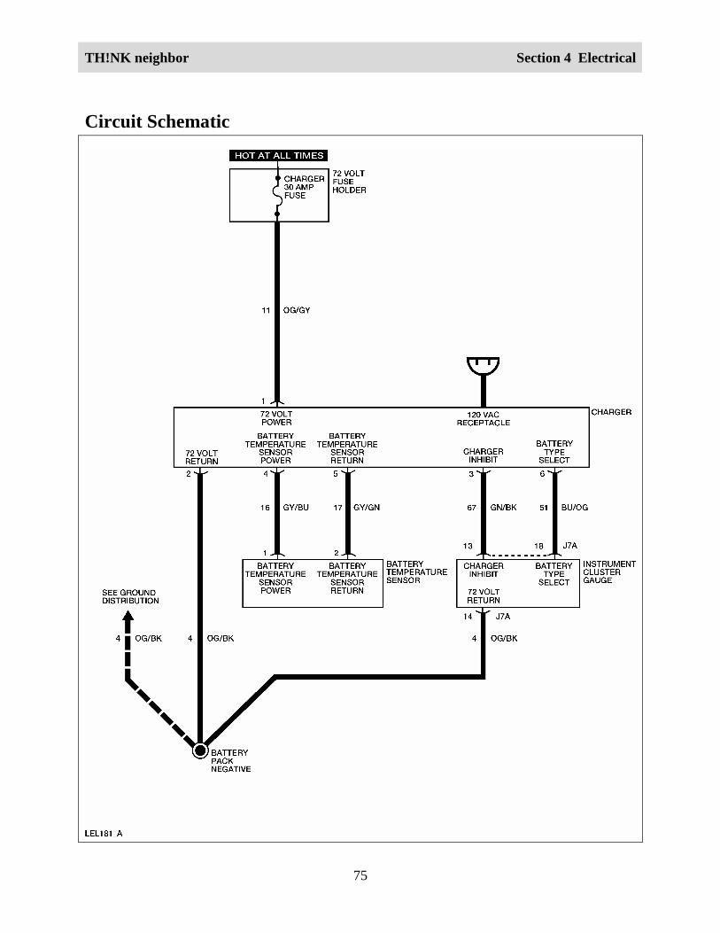
TH!NK neighbor Section 4 Electrical
75
Circuit Schematic

TH!NK neighbor Section 4 Electrical
76
Required ToolsHigh Voltage Insulated Gloves 100-F036 or equivalent
Face Shield 100-F035 or equivalent
System CheckFunctional components in the charging system are:
• GFCI cord
• Charger
• Service disconnect switch
• Battery temperature sensor
• Charger fuse
• Fuse cap
• Related wiring
Guidelines to diagnose the charging system:
1. Verify the concern.
2. Check the fuse(s).
3. Check all connectors and related wiring for partially seated terminals, connectors not matingproperly and for dirt, moisture or corrosion. For proper contact, terminal(s) must be free ofall foreign material.
4. Service disconnect switch must be in the ON position to charge batteries.
5. Make sure the instrument cluster gauge is set for the type of batteries that are installed in thevehicle. Refer to Battery Type Reprogramming in this section.
If the concern still exists, refer to the following table:

TH!NK neighbor Section 4 Electrical
77
Symptom ChartSymptom Possible Causes Action
The batteries do not charge • GFCI power cord
• Charger fuse
• Fuse cap
• Charger
• Battery (or batteries)
• Connectors or related wiring
GO to ChargerInoperative.
The batteries charge slowly(take too long to fullycharge)
• Charger
• Battery temperature sensor
• Connectors or related wiring
GO to Batteries ChargeSlowly.
The 120VAC indicator willnot display
• Instrument cluster gauge
• Connectors or related wiring
GO to 120VACEnergized IndicatorInoperative.
Charger InoperativeWARNING:
THE BATTERY PACK ASSEMBLY CAN DELIVER IN EXCESS OF 72 VOLTS OF DCPOWER. IMPROPER HANDLING OF THE BATTERY PACK CAN RESULT ININJURY OR FATALITY. ONLY AUTHORIZED PERSONNEL TRAINED TO WORKWITH BATTERY PACK COMPONENTS ARE PERMITTED TO HANDLE THEBATTERIES.
WARNING:
THE BATTERY PACK CONTAINS HIGH-VOLTAGE COMPONENTS AND WIRING.HIGH-VOLTAGE INSULATED SAFETY GLOVES AND FACE SHIELD MUST BEWORN WHEN PERFORMING THE FOLLOWING STEPS. FAILURE TO FOLLOWTHIS WARNING MAY RESULT IN SEVERE PERSONAL INJURY OR DEATH.
Step Action Connector EndView
1. Did you read the Circuit Description and Operation?
Yes - GO to Step 2.
No – REFER to Circuit Description and Operation in thissection.

TH!NK neighbor Section 4 Electrical
78
Step Action Connector EndView
2. 1. Disconnect the charger harness connector.
2. Connect a DVOM between the charger harness connectorterminal 1 and terminal 2.
Does the DVOM display approximately 72 volts?
Yes – GO to Step 3.
No – GO to Step 5.
Charger
3. 1. Reconnect the charger connector.
2. Connect the GFCI charger cord to the charger.
3. Verify charger operation by listening for a buzz noise andfeeling for a slight vibration from the charger.
Does the charger operate?
Yes – GO to Step 4.
No – GO to Step 8.
4. With the GFCI cord connected to the charger, connect aDVOM between the battery pack positive and battery packnegative.
Does the voltage increase after two minutes?
Yes – The system is OK.
No – TEST the batteries. REFER to Battery Test in thissection. If all batteries are OK, INSTALL a newcharger. REFER to Charger in this section. OPERATEthe system to verify the repair.
5. Connect a DVOM between the battery pack positive andbattery pack negative.
Does the DVOM display approximately 72 volts?
Yes – GO to Step 6.
No – TEST the batteries. REFER to Battery Test in thissection.
6. Connect a DVOM between the charger harness connectorterminal 2 and the battery pack negative.
Does continuity exist?
Yes – GO to Step 7.
Charger

TH!NK neighbor Section 4 Electrical
79
Step Action Connector EndView
No – INSTALL a new 72 volt harness. REFER to WiringHarnesses in this section. OPERATE the system toverify the repair.
7. 1. Perform the Power Shutdown Procedure. Refer to PowerShutdown Procedure in this section.
2. Connect a DVOM between the charger harness connectorterminal 1 and the battery pack positive.
Does continuity exist?
Yes – The system is OK.
No – INSPECT the fuse cap and INSTALL a new fuse cap ifnecessary. If the fuse cap is OK, INSTALL a new 72volt harness. REFER to Wiring Harnesses in thissection. OPERATE the system to verify the repair.
Charger
8. 1. Connect a known good GFCI cord to the charger.
2. Verify charger operation by listening for a buzz noiseand feeling for a slight vibration from the charger.
Does the charger operate?
Yes – INSTALL a new GFCI cord. OPERATE the system toverify the repair.
No – INSTALL a new charger. REFER to Charger in thissection. OPERATE the system to verify the repair.
Batteries Charge SlowlyWARNING:
THE BATTERY PACK ASSEMBLY CAN DELIVER IN EXCESS OF 72 VOLTS OF DCPOWER. IMPROPER HANDLING OF THE BATTERY PACK CAN RESULT ININJURY OR FATALITY. ONLY AUTHORIZED PERSONNEL TRAINED TO WORKWITH BATTERY PACK COMPONENTS ARE PERMITTED TO HANDLE THEBATTERIES.
WARNING:
THE BATTERY PACK CONTAINS HIGH-VOLTAGE COMPONENTS AND WIRING.HIGH-VOLTAGE INSULATED SAFETY GLOVES AND FACE SHIELD MUST BEWORN WHEN PERFORMING THE FOLLOWING STEPS. FAILURE TO FOLLOWTHIS WARNING MAY RESULT IN SEVERE PERSONAL INJURY OR DEATH.

TH!NK neighbor Section 4 Electrical
80
Step Action Connector EndView
1 Did you read the Circuit Description and Operation?
Yes - GO to Step 2.
No – REFER to Circuit Description and Operation in thissection.
2 1. Perform the Power Shutdown Procedure. Refer toPower Shutdown Procedure in this section.
2. Disconnect the charger harness connector.
3. Connect a DVOM between the charger harnessconnector terminal 4 and terminal 5.
Does the DVOM display between 8k and 12k ohms atapproximately 25 degrees C?
Yes – GO to Step 3.
No – GO to Step 4.
Charger
3 Measure the time required to bring batteries to a full state ofcharge.
Do the batteries charge fully in 8-10 hours?
Yes – The system is OK.
No – TEST the batteries. REFER to Battery Test in thissection. If all batteries are OK, INSTALL a newcharger. REFER to Charger in this section. OPERATEthe system to verify the repair.
4 1. Disconnect the battery temperature sensor harnessconnector.
2. Connect a DVOM between the battery temperaturesensor harness connector terminal 1 and terminal 2.
Does the DVOM display between 8k and 12k ohms atapproximately 25 degrees C?
Yes – GO to Step 5.
No – INSTALL a new battery temperature sensor.OPERATE the system to verify the repair.
Battery TemperatureSensor
5 Connect a DVOM between the battery temperature sensorharness connector terminal 1 and the charger harnessconnector terminal 4.
Battery TemperatureSensor
Charger

TH!NK neighbor Section 4 Electrical
81
Step Action Connector EndView
Does continuity exist?
Yes – GO to Step 6.
No – REPAIR circuit 16. OPERATE the system to verify therepair.
6 Connect a DVOM between the battery temperature sensorharness connector terminal 2 and the charger harnessconnector terminal 5.
Does continuity exist?
Yes – INSTALL a new charger. REFER to Charger in thissection. OPERATE the system to verify the repair.
No – REPAIR circuit 17. OPERATE the system to verify therepair.
Battery TemperatureSensor
Charger
Voltage Step DownCircuit Description and OperationThe DC/DC converter 1 (standard) and DC/DC converter 2 (optional) receive 72 volt powerthrough the DC/DC fuse when the service disconnect switch is in the ON position. The DC/DCconverter 1 (standard) and the DC/DC converter 2 (optional) step down the voltage from 72 voltsto 12 volts for vehicle systems that require 12 volt power, such as exterior lamps, wiper/washer,horn, etc. For diagnosis of the DC/DC converter 2 (optional) or the power point system, refer toPower Point in this section.

TH!NK neighbor Section 4 Electrical
82
Circuit Schematic

TH!NK neighbor Section 4 Electrical
83
Required ToolsHigh Voltage Insulated Gloves 100-F036 or equivalent
Face Shield 100-F035 or equivalent
System CheckFunctional components in the voltage step down system are:
• DC/DC converter 1 (standard)
• DC/DC fuse
• Service disconnect switch
• Related wiring
Guidelines to diagnose the voltage step down system:
1. Verify the concern.
2. Check the fuse(s).
3. Check all connectors and related wiring for partially seated terminals, connectors not matingproperly and for dirt, moisture or corrosion. For proper contact, terminal(s) must be free ofall foreign material.
4. Verify that the battery pack is fully charged. REFER to Battery in this section.
If the concern still exists, refer to the following table:
Symptom ChartSymptom Possible Causes Action
All 12 volt systems exceptpower point are inoperative
• DC/DC fuse
• DC/DC converter 1(standard)
• Connectors or relatedwiring
GO to
DC/DC Converter 1(Standard) Inoperative.

TH!NK neighbor Section 4 Electrical
84
DC/DC Converter 1 (Standard) InoperativeWARNING:
THE BATTERY PACK ASSEMBLY CAN DELIVER IN EXCESS OF 72 VOLTS OF DCPOWER. IMPROPER HANDLING OF THE BATTERY PACK CAN RESULT ININJURY OR FATALITY. ONLY AUTHORIZED PERSONNEL TRAINED TO WORKWITH BATTERY PACK COMPONENTS ARE PERMITTED TO HANDLE THEBATTERIES.
WARNING:
THE BATTERY PACK CONTAINS HIGH-VOLTAGE COMPONENTS AND WIRING.HIGH-VOLTAGE INSULATED SAFETY GLOVES AND FACE SHIELD MUST BEWORN WHEN PERFORMING THE FOLLOWING STEPS. FAILURE TO FOLLOWTHIS WARNING MAY RESULT IN SEVERE PERSONAL INJURY OR DEATH.
Step Action Connector EndView
1. Did you read the Circuit Description and Operation?
Yes - GO to Step 2.
No - REFER to Circuit Description and Operation inthis section.
2. Connect a DVOM between the DC/DC converter 1(standard) harness connector terminal 1 and terminal2.
Does the DVOM display approximately 12 volts?
Yes – The DC/DC converter (standard) is operatingcorrectly. CHECK operation of each 12 voltsystem to determine symptom.
No - GO to Step 3.
DC/DC Converter 1(Standard)
3. 1. Disconnect the DC/DC relay.
2. Remove the Horn/flasher/brake fuse.
3. Connect a DVOM between the DC/DC converter 1(standard) harness connector terminal 1 andterminal 2.
Does the DVOM display approximately 12 volts?
Yes – INSTALL a new DC/DC relay. OPERATE thesystem to verify the repair.
DC/DC Converter 1(Standard)
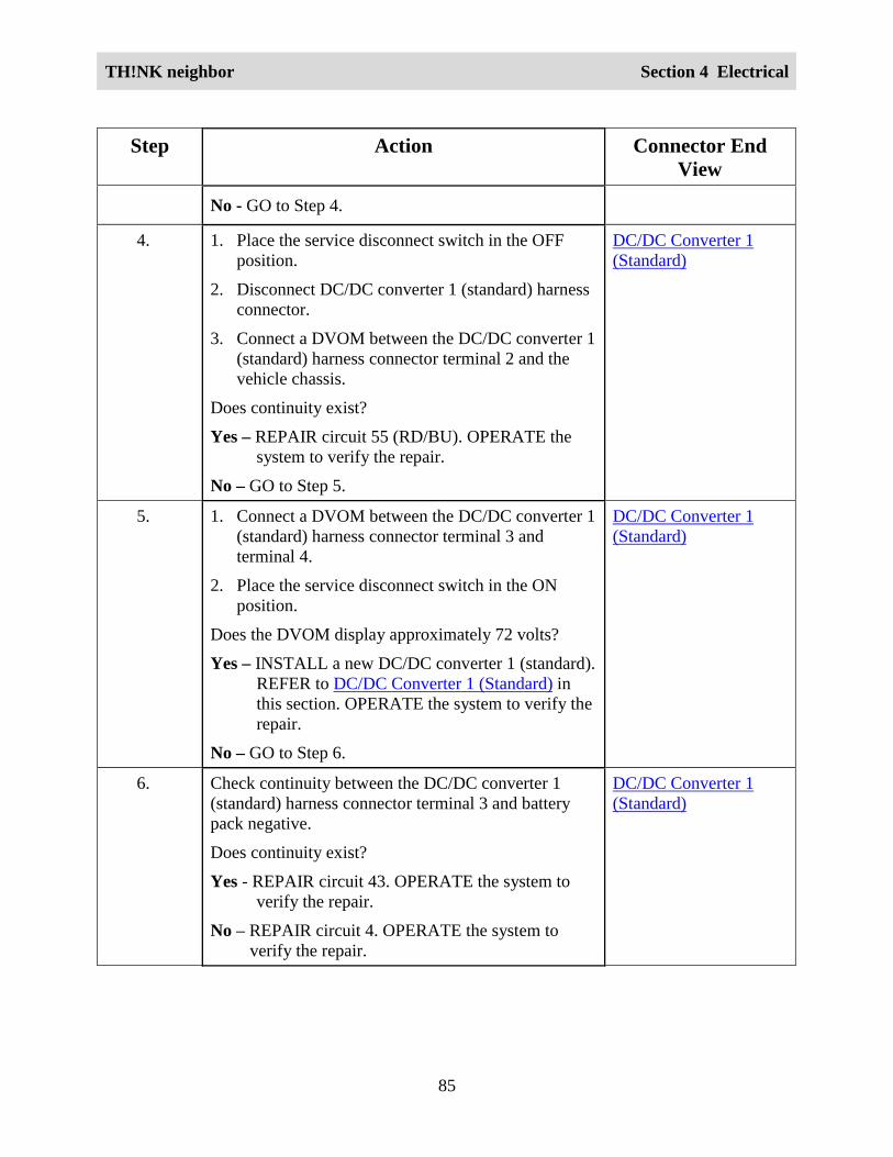
TH!NK neighbor Section 4 Electrical
85
Step Action Connector EndView
No - GO to Step 4.
4. 1. Place the service disconnect switch in the OFFposition.
2. Disconnect DC/DC converter 1 (standard) harnessconnector.
3. Connect a DVOM between the DC/DC converter 1(standard) harness connector terminal 2 and thevehicle chassis.
Does continuity exist?
Yes – REPAIR circuit 55 (RD/BU). OPERATE thesystem to verify the repair.
No – GO to Step 5.
DC/DC Converter 1(Standard)
5. 1. Connect a DVOM between the DC/DC converter 1(standard) harness connector terminal 3 andterminal 4.
2. Place the service disconnect switch in the ONposition.
Does the DVOM display approximately 72 volts?
Yes – INSTALL a new DC/DC converter 1 (standard).REFER to DC/DC Converter 1 (Standard) inthis section. OPERATE the system to verify therepair.
No – GO to Step 6.
DC/DC Converter 1(Standard)
6. Check continuity between the DC/DC converter 1(standard) harness connector terminal 3 and batterypack negative.
Does continuity exist?
Yes - REPAIR circuit 43. OPERATE the system toverify the repair.
No – REPAIR circuit 4. OPERATE the system toverify the repair.
DC/DC Converter 1(Standard)

TH!NK neighbor Section 4 Electrical
86
Exterior LampsCircuit Description and OperationThe headlamps operate only when the drive mode selector switch is in the Reverse, Turf or Driveposition. There are no high beam headlamps on this vehicle. The DC/DC converter 1 (standard)supplies 12 volt power through the DC/DC relay and the lights fuse to the multifunction switchconnector-L. When the headlamp switch is turned to the ON (2nd) position, 12 volt power issupplied to the headlamps. The DC/DC converter 1 (standard) supplies 12 volt return for theheadlamps to complete the circuit. The flash-to-pass function only operates when the headlampswitch is in the OFF or TAIL (1st) position.
The turn signals operate only when the drive mode selector switch is in the Reverse, Turf orDrive position. When the multifunction switch is in the LH or RH turn signal position, 12 voltpower is supplied to the turn signal lamps and to the instrument cluster gauge turn signalindicators. The lamps flash ON and OFF as the electronic flasher internal relay toggles. TheDC/DC converter 1 (standard) supplies 12 volt return for the lamps and the instrument clustergauge to complete the circuit.
The hazard lamps operate with the drive mode selector switch in any position. The DC/DCconverter 1 (standard) supplies 12 volt power through the horn/flasher/brake fuse to themultifunction switch connector-L. When the hazard switch (part of multifunction switch) is inthe ON position, 12 volt power is supplied to the turn signal lamps and to the instrument clustergauge turn signal indicators. The lamps and hazard switch will flash ON and OFF continuouslyuntil the hazard switch is placed in the OFF position. The DC/DC converter 1 (standard) suppliesthe 12 volt return for the lamps and the instrument cluster gauge to complete the circuit.
The brake lamps operate with the drive mode selector switch in any position. The center high-mounted stop lamp (CHMSL) is mounted on the rear of the vehicle roof. The CHMSL and thebrake lamps illuminate when the brake pedal is depressed. 12 volt power is supplied at all timesby the DC/DC converter 1 (standard) to the brake switch through the horn/flasher/brake fuse.The DC/DC converter 1 (standard) supplies 12 volt return for the CHMSL and the brake lamps.When the brake pedal is pressed, the brake switch closes and the brake lamps and CHMSLilluminate.
The reverse lamp illuminates when the drive mode selector switch is turned to the Reverseposition. The DC/DC converter 1 (standard) supplies 12 volt return for the reverse lamp. Whenthe drive mode selector switch is turned to the Reverse position, 12 volt power is supplied to thereverse lamp by the instrument cluster gauge and the reverse lamp illuminates.
The taillamps and the license plate lamp illuminate when the drive mode selector switch isturned to the Reverse, Turf or Drive position and the headlamp switch is turned to the TAIL (1st)or ON (2nd) position. When the headlamp switch is turned to the TAIL (1st) or ON (2nd) position,12 volt power is supplied to the taillamps and the license plate lamp. The DC/DC converter 1(standard) supplies 12 volt return for the taillamps and the license plate lamp.

TH!NK neighbor Section 4 Electrical
87
Circuit Schematic

TH!NK neighbor Section 4 Electrical
88
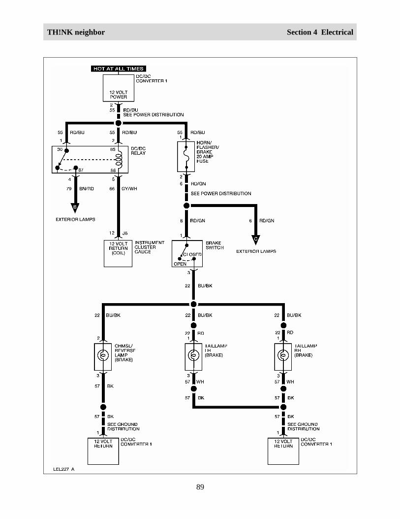
TH!NK neighbor Section 4 Electrical
89

TH!NK neighbor Section 4 Electrical
90

TH!NK neighbor Section 4 Electrical
91
System CheckFunctional components in the exterior lamps system are:
• Lights fuse
• Horn/flasher/brake fuse
• Multifunction switch
• Headlamps
• CHMSL/reverse lamp
• Taillamps
• License plate lamp
• Electronic flasher
• Hazard switch (part of multifunction switch)
• Brake switch
• Turn signal lamps
• Instrument cluster gauge
• Related wiring
Guidelines to diagnose the exterior lamps system:
1. Verify the concern.
2. Check fuse(s).
3. Check all connectors and related wiring for partially seated terminals, connectors not matingproperly and for dirt, moisture or corrosion. For proper contact, terminal(s) must be free ofall foreign material.
4. If a single lamp is inoperative, check and replace the bulb (if necessary) before performingfurther diagnosis.
If the concern still exists, refer to the following table:

TH!NK neighbor Section 4 Electrical
92
Symptom ChartSymptom Possible Causes Action
The headlamps areinoperative
• Lights fuse
• Bulbs
• Multifunction switch
• Connectors or related wiring
GO to HeadlampsInoperative.
One headlamp isinoperative
• Bulb
• Connectors or related wiring
GO to HeadlampsInoperative — OneLamp.
The headlamps are alwayson
• Multifunction switch
• Connectors or related wiring
GO to
Headlamp(s) AlwaysON.
The turn signal lamps areinoperative
• Lights fuse
• Horn/flasher/brake fuse
• Bulbs
• Multifunction switch
• Connectors or related wiring
GO to Turn SignalLamps Inoperative.
One turn signal lamp isinoperative
• Bulb
• Connectors or related wiring
GO to Turn SignalLamps Inoperative —Left or Right Side.
The turn signal lamps areinoperative — left or rightside
• Bulbs
• Connectors or related wiring
GO to Turn SignalLamps Inoperative —Left or Right Side.
The turn signal indicator isinoperative — left or rightside
• Instrument cluster gauge
• Connectors or related wiring
GO to Turn SignalIndicator Inoperative —Left or Right Side

TH!NK neighbor Section 4 Electrical
93
Symptom Possible Causes Action
The hazard flasher isinoperative (turn signalsoperate correctly)
• Multifunction switch INSTALL a newmultifunction switch.REFER to MultifunctionSwitch in this section.OPERATE the systemto verify the repair.
The hazard flasher switchillumination is inoperative
• Bulb INSTALL a new hazardflasher switch bulb.OPERATE the systemto verify the repair.
The hazard flasher isalways on
• Multifunction switch INSTALL a newmultifunction switch.REFER to MultifunctionSwitch in this section.OPERATE the systemto verify the repair.
The brake lamps areinoperative
• Horn/flasher/brake fuse
• Brake switch
• Connectors or related wiring
GO to Brake LampsInoperative.
One brake lamp isinoperative — left or rightside
• Bulb
• Connectors or related wiring
GO to One Brake LampInoperative — Left orRight Side.
The CHMSL is inoperative • Bulb
• Connectors or related wiringGO to CHMSLInoperative.
The brake lamps/CHMSL isalways on
• Brake switch
• Connectors or related wiringGO to BrakeLamps/CHMSL AlwaysON.
The reverse lamps areinoperative
• Instrument cluster gauge
• Connectors or related wiringGO to Reverse LampsInoperative.
The reverse lamps arealways on
• Instrument cluster gauge
• Connectors or related wiringGO to Reverse LampsAlways ON.
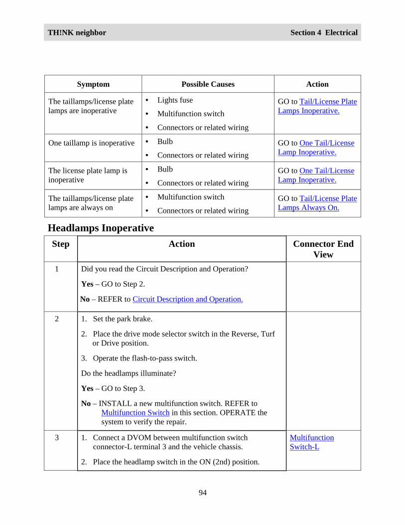
TH!NK neighbor Section 4 Electrical
94
Symptom Possible Causes Action
The taillamps/license platelamps are inoperative
• Lights fuse
• Multifunction switch
• Connectors or related wiring
GO to Tail/License PlateLamps Inoperative.
One taillamp is inoperative • Bulb
• Connectors or related wiringGO to One Tail/LicenseLamp Inoperative.
The license plate lamp isinoperative
• Bulb
• Connectors or related wiringGO to One Tail/LicenseLamp Inoperative.
The taillamps/license platelamps are always on
• Multifunction switch
• Connectors or related wiringGO to Tail/License PlateLamps Always On.
Headlamps InoperativeStep Action Connector End
View1 Did you read the Circuit Description and Operation?
Yes – GO to Step 2.
No – REFER to Circuit Description and Operation.
2 1. Set the park brake.
2. Place the drive mode selector switch in the Reverse, Turfor Drive position.
3. Operate the flash-to-pass switch.
Do the headlamps illuminate?
Yes – GO to Step 3.
No – INSTALL a new multifunction switch. REFER toMultifunction Switch in this section. OPERATE thesystem to verify the repair.
3 1. Connect a DVOM between multifunction switchconnector-L terminal 3 and the vehicle chassis.
2. Place the headlamp switch in the ON (2nd) position.
MultifunctionSwitch-L

TH!NK neighbor Section 4 Electrical
95
Step Action Connector EndView
Does the DVOM display approximately 12 volts?
Yes – REPAIR circuit 13. OPERATE the system to verify therepair.
No – INSTALL a new multifunction switch. REFER toMultifunction Switch in this section. OPERATE thesystem to verify the repair.
Headlamps Inoperative — One LampStep Action Connector End
View1 Did you read the Circuit Description and Operation?
Yes – GO to Step 2.
No – REFER to Circuit Description and Operation.
2 1. Disconnect the inoperative headlamp.
2. Set the park brake.
3. Place the drive mode selector switch in the Reverse, Turfor Drive position.
4. Place the headlamp switch in the ON (2nd) position.
5. Connect a DVOM between the inoperative headlampconnector terminal A and terminal B.
Does the DVOM display approximately 12 volts?
Yes – INSTALL a new headlamp bulb. REFER to HeadlampBulb. OPERATE the system to verify the repair.
No – REPAIR circuit 13. OPERATE the system to verify therepair.
Headlamp LH
Headlamp RH

TH!NK neighbor Section 4 Electrical
96
Headlamp(s) Always ONStep Action Connector End
View1 Did you read the Circuit Description and Operation?
Yes – GO to Step 2.
No – REFER to Circuit Description and Operation.
2 Disconnect the multifunction switch connector-L.
Do the headlamps illuminate?
Yes – REPAIR circuit 13 between the multifunction switchharness connector-L terminal 1 or terminal 3 and theheadlamps. OPERATE the system to verify the repair.
No – INSTALL a new multifunction switch. REFER toMultifunction Switch in this section. OPERATE thesystem to verify the repair.
MultifunctionSwitch-L
Turn Signal Lamps InoperativeStep Action Connector End
View1 Did you read the Circuit Description and Operation?
Yes - GO to Step 2.
No – REFER to Circuit Description and Operation.
2 Place the hazard switch in the ON position.
Do the hazard lamps operate correctly?
Yes - INSTALL a new multifunction switch. REFER toMultifunction Switch in this section. OPERATE thesystem to verify the repair.
No - GO to Step 3.
3 1. Disconnect the electronic flasher.
2. Connect a fused jumper wire between the electronic flasherconnector terminal 49a and terminal 49.
3. Turn on the left turn signals.
Do all left turn signals illuminate?
Yes – INSTALL a new electronic flasher. REFER to Electronic

TH!NK neighbor Section 4 Electrical
97
Step Action Connector EndView
Flasher in this section. OPERATE the system to verifythe repair.
No – INSTALL a new multifunction switch. REFER toMultifunction Switch in this section. OPERATE thesystem to verify the repair.
Turn Signal Lamps Inoperative — Left or Right SideStep Action Connector End
View 1 Did you read the Circuit Description and Operation?
Yes - GO to Step 2.
No - REFER to Circuit Description and Operation.
2 1. Disconnect an inoperative turn signal lamp.
2. Set the park brake.
3. Place the drive mode selector switch in the Reverse, Turf orDrive position.
4. Place the turn signal switch in the ON position (inoperativeside).
5. Connect a DVOM between the inoperative turn signal lampconnector terminal A and terminal B.
Does the DVOM display approximately 12 volts?
Yes – INSTALL a new bulb. OPERATE the system to verify therepair.
No – GO to Step 3.
Turn Signal LF
Turn Signal RF
Turn Signal LR
Turn Signal RR
3 Connect a DVOM between multifunction switch terminal 5 (LHside) or terminal 11 (RH side) and inoperative turn signal lamps.
Does continuity exist?
Yes – INSTALL a new multifunction switch. REFER toMultifunction Switch in this section. OPERATE thesystem to verify the repair.
No - REPAIR circuit 2 (RH side) or circuit 3 (LH side).OPERATE the system to verify the repair.
MultifunctionSwitch-L

TH!NK neighbor Section 4 Electrical
98
Turn Signal Indicator Inoperative — Left or Right SideStep Action Connector End
View1 Did you read the Circuit Description and Operation?
Yes - GO to Step 2.
No - REFER to Circuit Description and Operation.
2 1. Disconnect instrument cluster gauge connector J8.
2. Set the park brake.
3. Place the drive mode selector switch in the Reverse, Turf orDrive position.
4. Place the turn signal switch in the ON position (inoperativeside).
5. Connect a DVOM between instrument cluster connector J8terminal 5 (LH side) or terminal 6 (RH side) and terminal 4.
Does the DVOM display approximately 12 volts?
Yes – INSTALL a new instrument cluster gauge. REFER toInstrument Cluster Gauge in this section. OPERATE thesystem to verify the repair.
No - REPAIR circuit 5 (LH side) or circuit 6 (RH side).OPERATE the system to verify the repair.
Instrument ClusterGauge – J8
Brake Lamps InoperativeStep Action Connector
End View1 Did you read the Circuit Description and Operation?
Yes - GO to Step 2.
No - REFER to Circuit Description and Operation.
2 1. Disconnect the brake switch harness connector.
2. Connect a fused jumper wire between the brake switchconnector terminal 1 and terminal 3.
Do the brake lamps illuminate?
Yes - INSTALL a new brake switch. OPERATE the system toverify the repair.
No - REPAIR circuit 22. OPERATE the system to verify the repair.
Brake Switch

TH!NK neighbor Section 4 Electrical
99
One Brake Lamp Inoperative — Left or Right SideStep Action Connector End
View1 Did you read the Circuit Description and Operation?
Yes - GO to Step 2.
No - REFER to Circuit Description and Operation.
2 1. Disconnect the harness connector of the inoperative brakelamp.
2. Connect a DVOM between terminal 1 (taillamp LH or RHharness connector) or terminal 2 (CHMSL/reverse lampharness connector) and terminal 3 of the inoperative brakelamp.
3. Press the brake pedal.
Does the DVOM display approximately 12 volts?
Yes – INSTALL a new bulb. OPERATE the system to verify therepair.
No - REPAIR circuit 22. OPERATE the system to verify therepair.
Taillamp LH
Taillamp RH
CHMSL/ReverseLamp
CHMSL InoperativeStep Action Connector End
View1 Did you read the Circuit Description and Operation?
Yes - GO to Step 2.
No - REFER to Circuit Description and Operation.
2 1. Disconnect the CHMSL/reverse lamp harness connector.
2. Connect a DVOM between CHMSL/reverse lamp harnessconnector terminal 2 and terminal 3.
3. Press the brake pedal.
Does the DVOM display approximately 12 volts?
Yes – INSTALL a new bulb. OPERATE the system to verify therepair.
No - REPAIR circuit 22. OPERATE the system to verify therepair.
CHMSL/ReverseLamp

TH!NK neighbor Section 4 Electrical
100
Brake Lamps/CHMSL Always ONStep Action Connector End
View1 Did you read the Circuit Description and Operation?
Yes - GO to Step 2.
No - REFER to Circuit Description and Operation.
2 Disconnect the brake switch harness connector.
Do the brake lamps and CHMSL remain illuminated?
Yes - REPAIR circuit 22. OPERATE the system to verify therepair.
No – INSTALL a new brake switch. OPERATE the system toverify the repair.
Brake Switch
Reverse Lamps InoperativeStep Action Connector End
View1 Did you read the Circuit Description and Operation?
Yes - GO to Step 2.
No - REFER to Circuit Description and Operation.
2 1. Disconnect the CHMSL/reverse lamp harness connector.
2. Connect a DVOM between CHMSL/reverse lamp harnessconnector terminal 1 and terminal 3.
3. Set the park brake.
4. Place the drive mode selector switch in the Reverse position.
Does the DVOM display approximately 12 volts?
Yes – INSTALL new bulbs. OPERATE the system to verify therepair.
No – GO to Step 3.
CHMSL/ReverseLamp
3 Connect a DVOM between instrument cluster gauge connectorJ8 terminal 7 and the CHMSL/reverse lamp connector terminal1.
Does continuity exist?
Yes – INSTALL a new instrument cluster gauge. REFER toInstrument Cluster Gauge in this section. OPERATE the

TH!NK neighbor Section 4 Electrical
101
Step Action Connector EndView
system to verify the repair.
No – REPAIR circuit 68. OPERATE the system to verify therepair.
Reverse Lamps Always ONStep Action Connector End
View 1 Did you read the Circuit Description and Operation?
Yes - GO to Step 2.
No - REFER to Circuit Description and Operation.
2 1. Disconnect instrument cluster gauge harness connector J8.
2. Set the park brake.
3. Place the drive mode selector switch in the Drive position.
Do the reverse lamps remain illuminated?
Yes - REPAIR circuit 68. OPERATE the system to verify theREPAIR.
No – INSTALL a new instrument cluster gauge. REFER toInstrument Cluster Gauge in this section. OPERATE thesystem to verify the repair.
Tail/License Plate Lamps InoperativeStep Action Connector End
View1 Did you read the Circuit Description and Operation?
Yes - GO to Step 2.
No - REFER to Circuit Description and Operation.
2 Press the brake pedal.
Do the brake lamps illuminate?
Yes – GO to Step 3.
No – REFER to Brake Lamps Inoperative.
3 1. Connect a DVOM between multifunction switch harnessconnector-L terminal 6 and terminal 7.
MultifunctionSwitch-L

TH!NK neighbor Section 4 Electrical
102
Step Action Connector EndView
2. Set the park brake.
3. Place the drive mode selector switch in the Reverse, Turf orDrive position.
4. Place the headlamp switch in the TAIL (1st) position.
Does the DVOM display approximately 12 volts?
Yes – REPAIR circuit 14. OPERATE the system to verify therepair.
No – INSTALL a new multifunction switch. REFER toMultifunction Switch in this section. OPERATE thesystem to verify the repair.
One Tail/License Lamp InoperativeStep Action Connector End
View1 Did you read the Circuit Description and Operation?
Yes - GO to Step 2.
No - REFER to Circuit Description and Operation.
2 1. Disconnect the inoperative taillamp harness connector.
2. Set the park brake.
3. Place the drive mode selector switch in the Reverse, Turf orDrive position.
4. Place the headlamp switch in the TAIL (1st) position.
5. Connect a DVOM between the inoperative taillamp harnessconnector terminal 2 and terminal 3 (LH or RH taillamp) orterminal 1 (license plate lamp).
Does the DVOM display approximately 12 volts?
Yes – INSTALL a new bulb. OPERATE the system to verify therepair.
No – REPAIR circuit 14. OPERATE the system to verify therepair.
Taillamp LH
Taillamp RH
License Plate Lamp

TH!NK neighbor Section 4 Electrical
103
Tail/License Plate Lamps Always OnStep Action Connector End
View1 Did you read the Circuit Description and Operation?
Yes - GO to Step 2.
No - REFER to Circuit Description and Operation.
2 Disconnect the multifunction switch harness connector-L.
Are the taillamps and license plate lamp illuminated?
Yes - REPAIR circuit 14. OPERATE the system to verify therepair.
No – INSTALL a new multifunction switch. REFER toMultifunction Switch in this section. OPERATE thesystem to verify the repair.
MultifunctionSwitch – L
TH!NK neighbor Section 4 Electrical
104
Heater/DefoggerCircuit Description and OperationThe heater/defogger system consists of an electromechanical switch mounted on the cowl, heaterelement, fan, and contactor that are mounted on a bracket under the cowl, and two jumperharnesses which connect to the main harness and deliver power to the system. Two air vent hosesroute warm air from the heater box to air ducts mounted on the right and left sides of the cowl.
The system cannot be operated unless the vehicle is powered on (charging cord is disconnected,service disconnect switch is ON, and drive mode selector switch is in reverse, turf, or drive).When the heater switch is turned on, a microprocessor in the switch closes a relay in thecontactor to turn the system on. The switch has a built-in timer that will turn the system off after10 minutes. The switch may also be turned off any time during the 10-minute run cycle.
There are two jumper harnesses used on the heater/defogger. The 18A654 jumper harnessdelivers 72V from the main harness through the contactor mounted on the heater box to theheater element, then continuing through the DC/DC converter. The 18A586 jumper harnessdelivers 12V, when the vehicle is powered on and the drive mode selector switch is on, to closethe contactor and power the heater fan. The connector that connects the DC/DC converter to thisjumper harness is included on every vehicle. On vehicles without heater/defogger, this connectormay be used to provide power to aftermarket accessories such as lights, radio, etc. at thediscretion of the customer.
Using the heater/defogger for the full 10-minute cycle will consume approximately 25% of thecapacity of a completely charged battery pack.

TH!NK neighbor Section 4 Electrical
105
Circuit Schematic

TH!NK neighbor Section 4 Electrical
106

TH!NK neighbor Section 4 Electrical
107
System CheckFunctional components in the heater/defogger system are:
• Lamps fuse
• ACC fuse
• Heater/defogger switch
• DC/DC relay
• Heater blower control relay
• Heater
• Fan
• Vent hose
• Nylon clamps
• Related wiring
Guidelines to diagnose the heater/defogger system:
1. Verify the concern.
2. Check fuse(s).
3. Check all connectors and related wiring for partially seated terminals, connectors not matingproperly and for dirt, moisture or corrosion. For proper contact, terminal(s) must be free ofall foreign material.
If the concern still exists, refer to the following table:

TH!NK neighbor Section 4 Electrical
108
Symptom ChartSymptom Possible Causes Action
The fan is inoperative • Lamps fuse
• DC/DC relay
• Heater/defogger switch
• Fan
• Connectors or related wiring
GO to Fan Inoperative.
The fan is always on • Heater/defogger switch
• Connectors or related wiring
GO to Fan Always ON.
The fan runs but blows coolair
• Heater blower control relay
• Heater
• Heater/defogger contactor
• Connectors or related wiring
GO to HeaterInoperative.
The fan runs but no air isdirected to the windshield
• Heater/defogger ducts
• Nylon clamps
• Vent hose
INSPECT vent hoses fordamage, incorrectrouting or for looseconnection to ducts.INSPECT nylon clampsfor incorrect installation.REPAIR as necessary.
The fan runs but air isdirected to only one side ofthe windshield
• Heater/defogger ducts• Nylon clamps• Vent hose
INSPECT vent hoses fordamage, incorrectrouting or for looseconnection to ducts.INSPECT nylon clampsfor incorrect installation.REPAIR as necessary.
The fan runs but air volumeis low
• Heater/defogger ducts• Nylon clamps• Vent hose
INSPECT vent hoses fordamage, incorrectrouting or for looseconnection to ducts.INSPECT nylon clampsfor incorrect installation.REPAIR as necessary.
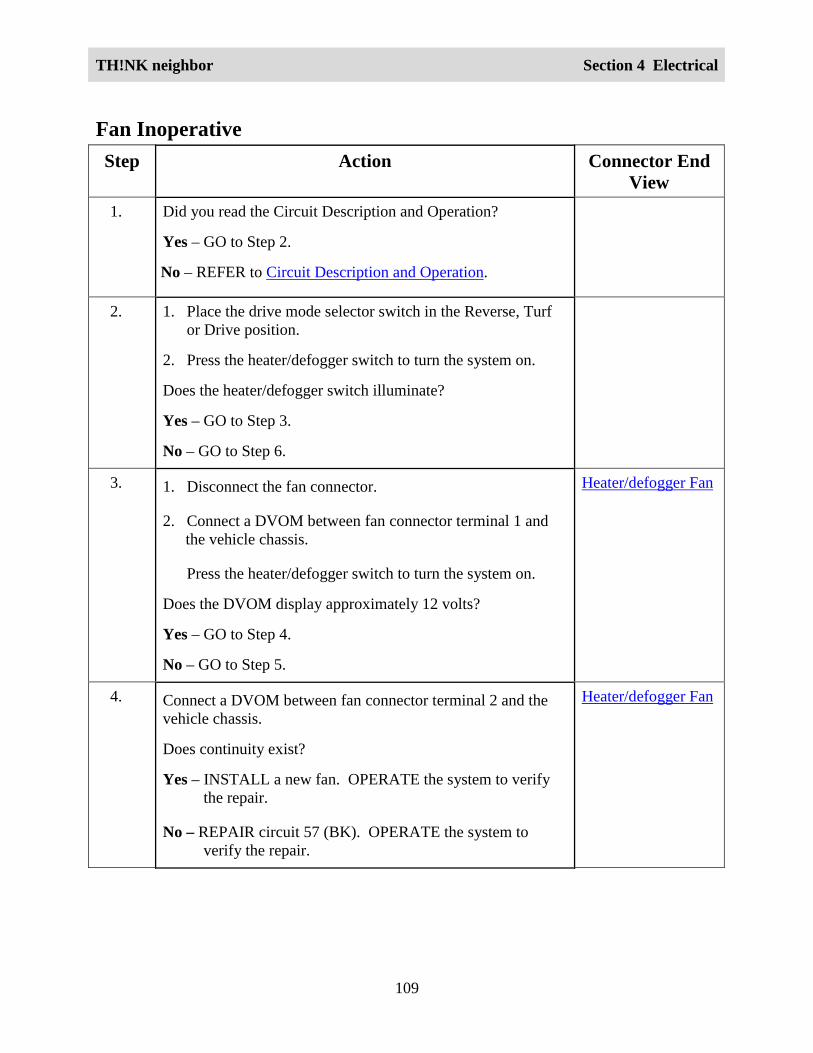
TH!NK neighbor Section 4 Electrical
109
Fan InoperativeStep Action Connector End
View1. Did you read the Circuit Description and Operation?
Yes – GO to Step 2.
No – REFER to Circuit Description and Operation.
2. 1. Place the drive mode selector switch in the Reverse, Turfor Drive position.
2. Press the heater/defogger switch to turn the system on.
Does the heater/defogger switch illuminate?
Yes – GO to Step 3.
No – GO to Step 6.
3. 1. Disconnect the fan connector.
2. Connect a DVOM between fan connector terminal 1 andthe vehicle chassis.
Press the heater/defogger switch to turn the system on.
Does the DVOM display approximately 12 volts?
Yes – GO to Step 4.
No – GO to Step 5.
Heater/defogger Fan
4. Connect a DVOM between fan connector terminal 2 and thevehicle chassis.
Does continuity exist?
Yes – INSTALL a new fan. OPERATE the system to verifythe repair.
No – REPAIR circuit 57 (BK). OPERATE the system toverify the repair.
Heater/defogger Fan

TH!NK neighbor Section 4 Electrical
110
5. 1. Disconnect heater/defogger switch connector.
2. Connect a DVOM between fan connector terminal 1 andheater/defogger switch connector terminal 1.
Does continuity exist?
Yes – INSTALL a new heater/defogger switch. OPERATEthe system to verify the repair.
No – REPAIR circuit 81 (RD). OPERATE the system toverify the repair.
Heater/defogger Fan
Heater/defoggerSwitch
6. 1. Disconnect the heater/defogger switch connector.
2. Connect a DVOM between heater/defogger switchterminal 2 and the vehicle chassis, and betweenheater/defogger switch terminal 3 and the vehicle chassis.
Does the DVOM display approximately 12 volts?
Yes – REPAIR circuit 57 (BK). OPERATE the system toverify the repair.
No – REPAIR circuit 80 (RD/GN) or circuit 69 (RD/GY).OPERATE the system to verify the repair.
Heater/defoggerSwitch
Fan Always ONStep Action Connector End
View1 Did you read the Circuit Description and Operation?
Yes – GO to Step 2.
No – REFER to Circuit Description and Operation.

TH!NK neighbor Section 4 Electrical
111
Step Action Connector EndView
2 1. Disconnect the heater/defogger switch.
2. Place the drive mode selector switch in the reverse, turfor drive position.
3. Check operation of the fan.
Does the fan still run?
Yes – REPAIR circuit 81 (RD). OPERATE the system toverify the repair.
No – INSTALL a new heater/defogger switch. OPERATE thesystem to verify the repair.
Heater InoperativeStep Action Connector End
View1 Did you read the Circuit Description and Operation?
Yes – GO to Step 2.
No – REFER to Circuit Description and Operation.
2 1. Place the drive mode selector switch in the Reverse, Turfor Drive position.
2. Press the heater/defogger switch to turn the system onwhile listening for noise from the heater/defoggercontactor.
Does the heater/defogger contactor click when the system isturned on?
Yes – GO to Step 3.
No – GO to Step 7.
3 1. Disconnect the heater/defogger contactor.
2. Connect a DVOM between heater/defogger contactorterminal A1 and the vehicle chassis.
Does the DVOM display approximately 72 volts?
Heater/defoggerContactor
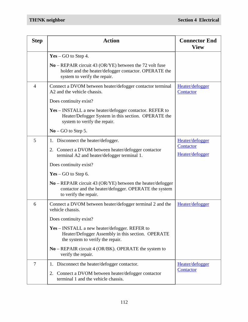
TH!NK neighbor Section 4 Electrical
112
Step Action Connector EndView
Yes – GO to Step 4.
No – REPAIR circuit 43 (OR/YE) between the 72 volt fuseholder and the heater/defogger contactor. OPERATE thesystem to verify the repair.
4 Connect a DVOM between heater/defogger contactor terminalA2 and the vehicle chassis.
Does continuity exist?
Yes – INSTALL a new heater/defogger contactor. REFER toHeater/Defogger System in this section. OPERATE thesystem to verify the repair.
No – GO to Step 5.
Heater/defoggerContactor
5 1. Disconnect the heater/defogger.
2. Connect a DVOM between heater/defogger contactorterminal A2 and heater/defogger terminal 1.
Does continuity exist?
Yes – GO to Step 6.
No – REPAIR circuit 43 (OR/YE) between the heater/defoggercontactor and the heater/defogger. OPERATE the systemto verify the repair.
Heater/defoggerContactor
Heater/defogger
6 Connect a DVOM between heater/defogger terminal 2 and thevehicle chassis.
Does continuity exist?
Yes – INSTALL a new heater/defogger. REFER toHeater/Defogger Assembly in this section. OPERATEthe system to verify the repair.
No – REPAIR circuit 4 (OR/BK). OPERATE the system toverify the repair.
Heater/defogger
7 1. Disconnect the heater/defogger contactor.
2. Connect a DVOM between heater/defogger contactorterminal 1 and the vehicle chassis.
Heater/defoggerContactor

TH!NK neighbor Section 4 Electrical
113
Step Action Connector EndView
Does the DVOM display approximately 12 volts?
Yes – GO to Step 8.
No – REPAIR circuit 81 (RD). OPERATE the system to verifythe repair.
8 Connect a DVOM between heater/defogger terminal 2 and thevehicle chassis.
Does continuity exist?
Yes – INSTALL a new heater/defogger contactor. REFER toHeater/Defogger System in this section. OPERATE thesystem to verify the repair.
No – REPAIR circuit 57 (RD). OPERATE the system to verifythe repair.
Heater/defogger
HornCircuit Description and OperationThe horn will sound any time the horn switch is pressed. The DC/DC converter 1 (standard)supplies 12 volt power through the horn/flasher/brake fuse to the multifunction switch and thehorn. When the horn switch is pressed, 12 volt power is supplied to the horn relay coil, whichcloses the horn relay switch, providing a 12 volt return for the horn. This completes the circuitand the horn will sound.

TH!NK neighbor Section 4 Electrical
114
Circuit Schematic
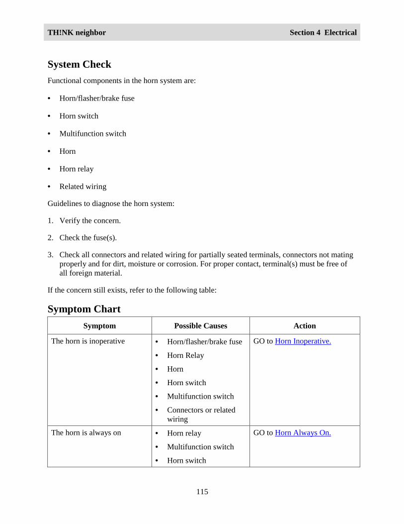
TH!NK neighbor Section 4 Electrical
115
System CheckFunctional components in the horn system are:
• Horn/flasher/brake fuse
• Horn switch
• Multifunction switch
• Horn
• Horn relay
• Related wiring
Guidelines to diagnose the horn system:
1. Verify the concern.
2. Check the fuse(s).
3. Check all connectors and related wiring for partially seated terminals, connectors not matingproperly and for dirt, moisture or corrosion. For proper contact, terminal(s) must be free ofall foreign material.
If the concern still exists, refer to the following table:
Symptom ChartSymptom Possible Causes Action
The horn is inoperative • Horn/flasher/brake fuse
• Horn Relay
• Horn
• Horn switch
• Multifunction switch
• Connectors or relatedwiring
GO to Horn Inoperative.
The horn is always on • Horn relay
• Multifunction switch
• Horn switch
GO to Horn Always On.

TH!NK neighbor Section 4 Electrical
116
Symptom Possible Causes Action
• Connectors or relatedwiring
Horn InoperativeStep Action Connector End
View1 Did you read the Circuit Description and Operation?
Yes – GO to Step 2.
No – REFER to Circuit Description and Operation.
2 Place the hazard switch in the ON position.
Do the hazard lamps operate properly?
Yes – GO to Step 3.
No – REFER to DC/DC Converter 1 (Standard) Inoperative.
3 1. Disconnect the horn relay harness connector.
2. Connect a DVOM between the horn relay harness connectorterminal 2 and the vehicle chassis.
3. Press the horn switch.
Does the DVOM display approximately 12 volts?
Yes – GO to Step 4.
No – GO to Step 8.
Horn Relay
4 Connect a DVOM between the horn relay harness connectorterminal 4 and the vehicle chassis.
Does the DVOM display approximately 12 volts?
Yes – GO to Step 5.
No – GO to Step 6.
Horn Relay
5 1. Check continuity between the horn relay harness connectorterminal 1 and the vehicle chassis.
2. Check continuity between the horn relay harness connectorterminal 5 and the vehicle chassis.
Does continuity exist?
Yes – INSTALL a new horn relay. OPERATE the system toverify the repair.
Horn Relay

TH!NK neighbor Section 4 Electrical
117
Step Action Connector EndView
No – REPAIR circuit 57. OPERATE the system to verify therepair.
6 1. Disconnect the horn harness connector.2. Connect a DVOM between the horn harness connector
terminal 1 and the vehicle chassis.Does the DVOM display approximately 12 volts?Yes – GO to Step 7.No – REPAIR circuit 6. OPERATE the system to verify the
repair.
Horn
7 Check continuity between the horn harness connector terminal2 and the horn relay harness connector terminal 4.Does continuity exist?Yes – INSTALL a new horn. OPERATE the system to verify
the repair.No – REPAIR circuit 78. OPERATE the system to verify the
repair.
HornHorn Relay
8 1. Disconnect the multifunction switch harness connectors.2. Connect a DVOM between the multifunction switch harness
connector L terminal 10 and the vehicle chassis.Does the DVOM display approximately 12 volts?Yes – GO to Step 9.No - REPAIR circuit 6. OPERATE the system to verify the
repair.
MultifunctionSwitch - L
9 Check continuity between the multifunction switch harnessconnector W terminal 11 and the horn relay harness connectorterminal 2.Does continuity exist?Yes – GO to Step 10.No – REPAIR circuit 28. OPERATE the system to verify the
repair.
MultifunctionSwitch - WHorn Relay

TH!NK neighbor Section 4 Electrical
118
Step Action Connector EndView
10 1. Disconnect the horn switch harness connector.2. Check continuity between the horn switch harness
connector terminal 1 and the multifunction switch harnessconnector W terminal 11.
3. Check continuity between the horn switch harnessconnector terminal 2 and the multifunction switch harnessconnector L terminal 10.
Does continuity exist?Yes – INSTALL a new horn switch. REFER to Horn Switch in
this section. OPERATE the system to verify the repair.No – INSTALL a new multifunction switch. REFER to
Multifunction Switch in this section. OPERATE thesystem to verify the repair.
Horn SwitchMultifunctionSwitch-WMultifunctionSwitch-L
Horn Always OnStep Action Connector End
View1 Did you read the Circuit Description and Operation?
Yes – GO to Step 2.
No – REFER to Circuit Description and Operation.
2 Disconnect the horn relay harness connector.
Does the horn stop sounding?
Yes – GO to Step 3.
No – REPAIR circuit 78. OPERATE the system to verify therepair.
3 Connect a DVOM between the horn relay harness connectorterminal 2 and the vehicle chassis.
Does the DVOM display approximately 12 volts?
Yes – GO to Step 4.
No – INSTALL a new horn relay. OPERATE the system toverify the repair.
Horn Relay
4 1. Disconnect the multifunction switch harness connector W.
2. Connect a DVOM between the horn relay harness connectorterminal 2 and the vehicle chassis.
Horn Relay

TH!NK neighbor Section 4 Electrical
119
Step Action Connector EndView
Does the DVOM display approximately 12 volts?
Yes – REPAIR circuit 28. OPERATE the system to verify therepair.
No – RECONNECT multifunction switch connector W. GO toStep 5.
5 1. Disconnect the horn switch harness connector.
2. Connect a DVOM between the horn relay harness connectorterminal 2 and the vehicle chassis.
Does the DVOM display approximately 12 volts?
Yes – INSTALL a new multifunction switch. REFER toMultifunction Switch in this section. OPERATE thesystem to verify the repair.
No – INSTALL a new horn switch. REFER to Horn Switch inthis section. OPERATE the system to verify the repair.
Horn Switch
Horn Relay
Instrument Cluster GaugeCircuit Description and OperationThe instrument cluster gauge is the main component of the electrical system. The fourconnectors on the back of the instrument cluster gauge are for the drive mode selector switch, the12 volt harness, the 72 volt harness and the gauge overlay (for the Select/Reset Button). Theinstrument cluster gauge backlighting illuminates when the drive mode selector switch is placedin the Reverse, Turf or Drive position.
The brake indicator will display when either the park brake is engaged or the brake fluid level islow. The park brake switch closes when the park brake is set. The 12 volt return is suppliedthrough the instrument cluster gauge from the DC/DC converter 1 to complete the circuit. Whenthe brake fluid in the master cylinder is low, the brake fluid level switch closes. The 12 voltreturn is supplied through the instrument cluster gauge from the DC/DC converter 1 to completethe circuit. The instrument cluster gauge will display the park brake/fluid warning/rollawayreminder indicator when these conditions are met.
The warning chime is built into the instrument cluster gauge and provides audible warning whenthe drive mode selector switch is in the Reverse position. The audible warning also sounds for 10seconds (as a rollaway reminder) when the drive mode selector switch is placed in the OFFposition from any other position unless the park brake is engaged.

TH!NK neighbor Section 4 Electrical
120
When the GFCI cord is connected to the charger, a signal is sent to the instrument cluster gauge.This signal activates the 120VAC energized indicator. This signal also inhibits the vehicle fromactivating any of the drive modes.
The battery water reminder indicator (flooded batteries only) will display every 300 miles (483km) on vehicles equipped with flooded batteries. To reset the battery water reminder indicator,refer to Resetting the Battery Water Reminder in this section. The instrument cluster gauge mustbe set for the type of batteries that are installed in the vehicle to prevent excessive charge time ordamage to the batteries. Refer to Selecting Battery Type in this section.
The drive system over-temp indicator will display when the drive system overheats. A fault codefrom the motor controller will activate the over-temp indicator. The indicator will remain onuntil the fault code from the motor controller disappears.
The electrical leakage indicator will display when electrical current is detected between the 72volt harness or components and the vehicle chassis. The indicator will display regardless of thedrive mode selector switch position. Although this condition may not affect the drive oraccessory system functionality, the display of the electrical leakage indicator indicates a need forservice. Make sure the vehicle is thoroughly dry before attempting electrical leakage diagnosis.Electrical leakage may be detected if certain electrical connectors are exposed to moisture due torain or washing of the vehicle.
The odometer has five LCD positions that display total vehicle miles/kilometers. These positionsare shared with the trip odometer. All digits will be displayed when in the odometer mode(trailing zeros will all be displayed). Refer to Selecting Odometer or Trip Odometer Mode in thissection. The trip odometer starts with one digit and one decimal place (e.g. 0.0). More digits willbe displayed as trip odometer counts up. Mileage is stored in non-volatile memory. In the eventof unexpected power loss, software flash or placing the drive mode selector switch in the OFFposition, mileage data will be maintained.
The seatbelt warning indicator will display for 30 seconds when the drive mode selector switchis placed in the Drive position. Switching to the Turf or Reverse position during the 30 secondperiod will not affect the timer for the indicator. Placing the drive mode selector switch in theOFF position is the only way to clear the indicator before the 30 seconds has elapsed.
The service required (wrench) indicator will be displayed anytime a diagnostic trouble code setsdue to a system malfunction.
The speedometer has two LCD positions that will display the vehicle speed in MPH or KPH,depending on the selected display mode. Refer to Selecting Speed and Distance Units in thissection. The speedometer will function when the vehicle is in the Reverse, Turf or Drivepositions.
The state of charge indicator displays the charge level of the battery pack. The number oflines/bars displayed indicates the state of charge. The motor controller outputs this information tothe instrument cluster gauge through the serial communication lines. The State of Charge

TH!NK neighbor Section 4 Electrical
121
Indicator Chart shows the battery pack voltage and corresponding instrument cluster gaugedisplay.
The left and right turn signal indicators are green LEDs that flash with their respective turnsignals.
State of Charge Indicator ChartBattery PackVoltage(Approximate)
State of ChargeIndicator BarsDisplayed
State of ChargeIndicator BatteryOutline Display
Additional Information
0 - 20 V 0 (or 5) bars Flashing fast Charger hums but does not charge.Vehicle will not drive.
20 - 63 V 0 (or 5) bars Flashing fast Charger charges at 2 amp rate.Vehicle will not drive.
63 - 68 V 0 (or 5) bars Flashing fast Charger charges at 10 amp rate.Vehicle will not drive.
68.3 – 69.8 V 0 (or 5) bars Flashing fast Charger charges at 10 amp rate.Vehicle will drive.
69.8 – 70.6 V 1 bar Flashing slow Charger charges at 10 amp rate.Vehicle will drive.
70.6 – 72 V 2 bars Solid Charger charges at 10 amp rate.Vehicle will drive.
72 – 73.4 V 3 bars Solid Charger charges at 10 amp rate.Vehicle will drive.
73.4 – 74.9 V 4 bars Solid Charger charges at 10 amp rate.Vehicle will drive.
74.9 – 80 V 5 bars Solid Charger charges at 10 amp rate.Vehicle will drive.
Selecting Speed and Distance UnitsTo change the speed and distance units between miles per hour (MPH) and kilometers per hour(KPH), set the park brake and perform the following:
1. While pressing the Select/Reset button, place the drive mode selector switch in the Driveposition.
2. Release the Select/Reset button within 5 seconds.

TH!NK neighbor Section 4 Electrical
122
3. Place the drive mode selector switch in the Turf position.
4. Press and release the Select/Reset button to alternate between MPH and KPH display.
5. Place the drive mode selector switch in the OFF position and either press the Select/Resetbutton or wait 10 seconds to exit.
The MPH and KPH indicators are the only items displayed when the instrument cluster gauge isin Selecting Speed and Distance Units mode.
Selecting Odometer or Trip Odometer ModeTo change the instrument cluster gauge display between the Odometer and the Trip Odometermode, set the park brake and perform the following:
1. Place the drive mode selector switch in the Drive or Turf position.
2. Press and release the Select/Reset button within three seconds.
Resetting the Trip OdometerTo reset the trip odometer, set the park brake and perform the following:
1. Place the drive mode selector switch in the Drive or Turf position.
2. Set the odometer to the Trip mode. Refer to Selecting Odometer or Trip Odometer Mode inthis section.
3. Press and hold the Select/Reset button for longer than three seconds.
Resetting the Battery Water ReminderTo reset the battery water reminder, set the park brake and perform the following:
1. Place the drive mode selector switch in the Reverse position.
2. Press and hold the Select/Reset button for longer than three seconds.

TH!NK neighbor Section 4 Electrical
123
Circuit Diagram
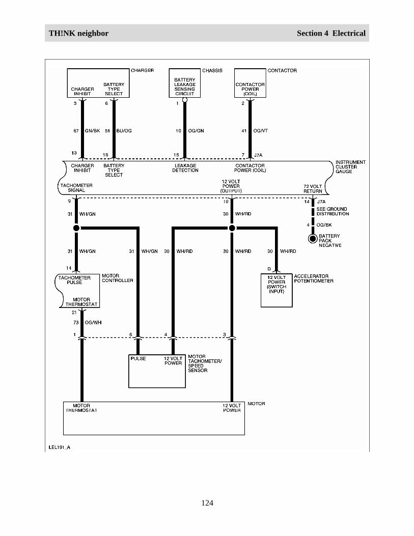
TH!NK neighbor Section 4 Electrical
124

TH!NK neighbor Section 4 Electrical
125

TH!NK neighbor Section 4 Electrical
126
Required ToolsHigh Voltage Insulated Gloves 100-F036 or equivalent
Face Shield 100-F035 or equivalent
System CheckFunctional components in the instrument cluster gauge system are:
• Service disconnect switch
• Instrument cluster gauge
• Control fuse
• Horn/flasher/brake fuse
• Lights fuse
• Motor controller
• Motor tachometer/speed sensor
• Accelerator potentiometer
• Charger
• Chassis
• Drive mode selector switch
• DC/DC converter 1 (standard)
• DC/DC relay
• Multifunction switch
• Brake fluid level switch
• Park brake switch
• CHMSL/reverse lamp
• Related wiring

TH!NK neighbor Section 4 Electrical
127
Guidelines to diagnose the instrument cluster gauge system:
1. Verify the concern.
2. Check the fuse(s).
3. Check all connectors and related wiring for partially seated terminals, connectors not matingproperly and for dirt, moisture or corrosion. For proper contact, terminal(s) must be free ofall foreign material.
4. Make sure the service disconnect switch is in the ON position.
5. Fill the brake fluid reservoir as necessary.
6. Check for any diagnostic trouble codes. Refer to Retrieving and Clearing DTCs.
If the concern still exists, refer to the following table:
Symptom ChartSymptom Possible Causes Action
The instrument cluster gaugedoes not illuminate with thedrive mode selector switch inthe Reverse, Turf or Driveposition
• Drive mode selectorswitch
• Instrument cluster gauge
• Connectors or relatedwiring
GO to Instrument ClusterGauge .
The state of charge indicatoris inoperative
• Instrument cluster gauge
• Motor controller
• Connectors or relatedwiring
GO to State of ChargeIndicator Inoperative.
The speedometer indicator isinoperative
• Instrument cluster gauge
• Motor tachometer/speedsensor
• Connectors or relatedwiring
GO to Instrument ClusterGauge Does Not DisplayCorrect Vehicle Speed.
The odometer/trip odometer isinoperative
• Instrument cluster gauge
• Connectors or relatedwiring
GO to Odometer/TripOdometer Inoperative.
The park brake/rollawayreminder chime is always on
• Instrument cluster gauge INSTALL a new instrumentcluster gauge. REFER to

TH!NK neighbor Section 4 Electrical
128
Symptom Possible Causes ActionInstrument Cluster Gauge inthis section. OPERATE thesystem to verify the repair.
The reverse chime is alwayson
• Instrument cluster gauge INSTALL a new instrumentcluster gauge. REFER toInstrument Cluster Gauge inthis section. OPERATE thesystem to verify the repair.
The reverse chime is alwayson
• Instrument cluster gauge INSTALL a new instrumentcluster gauge. REFER toInstrument Cluster Gauge inthis section. OPERATE thesystem to verify the repair.
The park brake/rollawayreminder chime is inoperative
• Instrument cluster gauge
• Park brake switch
• Connectors or relatedwiring
GO to Park Brake/ RollawayReminder Chime Inoperative.
The seatbelt warning indicatoris always on
• Instrument cluster gauge
• Connectors or relatedwiring
GO to
Seatbelt Warning IndicatorAlways On.
The seatbelt warning indicatoris inoperative
• Instrument cluster gauge INSTALL a new instrumentcluster gauge. REFER toInstrument Cluster Gauge inthis section. OPERATE thesystem to verify the repair.
The battery water reminderindicator is always on
• Instrument cluster gauge
• Connectors or relatedwiring
GO to Battery WaterReminder Indicator AlwaysOn.
The battery water reminderindicator is inoperative
• Instrument cluster gauge
• Incorrect battery typeselected
GO to Battery WaterReminder IndicatorInoperative.
The electrical leakageindicator is always on
• Instrument cluster gauge
• Connectors or relatedwiring
GO to Electrical LeakageIndicator Always On.
When the GFCI charger cordis connected to the charger,
• Instrument cluster gauge GO to 120VAC Energized

TH!NK neighbor Section 4 Electrical
129
Symptom Possible Causes Actionthe 120VAC energizedindicator does not display
• Connectors or relatedwiring
Indicator Inoperative.
The 120VAC energizedindicator is always on
• Instrument cluster gauge
• Connectors or relatedwiring
GO to 120VAC EnergizedIndicator Always On.
The service required (wrench)indicator is always on
• Instrument cluster gauge
• Connectors or relatedwiring
GO to Service RequiredIndicator Always On.
The drive system over-tempindicator is always on butvehicle has normalperformance
• Instrument cluster gauge INSTALL a new instrumentcluster gauge. REFER toInstrument Cluster Gauge inthis section. TEST the systemto verify the repair.
The drive system over-tempindicator is always on andvehicle has sluggishperformance
• Instrument cluster gauge
• Connectors or relatedwiring
GO to Drive System Over-Temp Indicator Always On.
The park brake indicator doesnot turn on when the parkbrake is applied
• Parking brake switch
• Connectors or relatedwiring
GO to Park Brake/FluidWarning/Rollaway ReminderIndicator Inoperative.
The brake warning indicatoris always on
• Brake fluid switch
• Parking brake switch
• Connectors or relatedwiring
GO to Park Brake/FluidWarning/Rollaway ReminderIndicator Always On.
Diagnostic System CheckNote: Before performing the diagnostic system check, perform the following:
1. Set the park brake.
2. Cycle the service disconnect switch OFF and then ON.
3. Place the drive mode selector switch in the Drive position, then to the OFF position.
4. Check all vehicle fuses.

TH!NK neighbor Section 4 Electrical
130
The Diagnostic System Check helps identify and diagnose the instrument cluster gauge andrelated vehicle system failures. Use the chart below as a starting point for all instrument clustergauge diagnosis.
Step Action Connector EndView
1 Attempt to enter Selecting Battery Type mode. Refer toSelecting Battery Type in this section.
Does the instrument cluster gauge enter Selecting BatteryType mode?
Yes - GO to Step 2.
No - REFER to Instrument Cluster Gauge in this section.
2 Attempt to enter Selecting Speed and Distance Units mode.Refer to Selecting Speed and Distance Units.
Does the instrument cluster gauge enter Selecting Speedand Distance Units mode?
Yes - GO to Step 3.
No - REFER to Instrument Cluster Gauge in this section.
3 Attempt to enter Retrieving and Clearing DTCs mode.Refer to Retrieving and Clearing DTCs.
Does the instrument cluster gauge enter Retrieving andClearing DTCs mode?
Yes - GO to Step 4.
No - REFER to Instrument Cluster Gauge Inoperative inthis section.
4 Does the instrument cluster gauge display any DTCs?
Yes - REFER to Diagnostic Trouble Code (DTC) Chart.
No - REFER to Symptom Chart in this section.

TH!NK neighbor Section 4 Electrical
131
DC/DC Relay TestStep Action Connector End
View1 1. Set the park brake.
2. Place the drive mode selector switch in the Reverse,Turf or Drive position.
Does the horn sound?Yes - GO to Step 2.No - REFER to Horn Inoperative in this section.
2 1. Disconnect the DC/DC relay harness connector.2. Connect a DVOM between the DC/DC relay harness
connector terminal 1 and the vehicle chassis.3. Connect a DVOM between the DC/DC relay harness
connector terminal 2 and the vehicle chassis.Does the display approximately 12 volts?Yes – GO to Step 3.
No – REPAIR circuit 55. OPERATE the system to verifythe repair.
DC/DC Relay
3 Connect a DVOM between the DC/DC relay harnessconnector terminal 1 and terminal 5.Does the display approximately 12 volts?Yes – GO to Step 5.No – GO to Step 4.
DC/DC Relay
4 1. Disconnect the instrument cluster gauge harnessconnector J8.
2. Connect a DVOM between the instrument clustergauge harness connector J8 terminal 12 and the DC/DCrelay harness connector terminal 5.
Does continuity exist?Yes – INSTALL a new instrument cluster gauge. REFERto Instrument Cluster Gauge in this section. OPERATE thesystem to verify the repair.No – REPAIR circuit 66. OPERATE the system to verifythe repair.
Instrument ClusterGauge – J8DC/DC Relay
5 1. Remove the lights fuse.2. Remove the wiper/washer fuse.3. Connect a DVOM between the DC/DC relay harness
connector terminal 4 and the lights fuse terminal 1.
DC/DC Relay

TH!NK neighbor Section 4 Electrical
132
Step Action Connector EndView
4. Connect a DVOM between the DC/DC relay harnessconnector terminal 4 and the wiper/washer fuseterminal 1.
Does continuity exist?Yes – GO to Step 6.No – REPAIR circuit 79. OPERATE the system to verifythe repair.
6 1. Remove the lights fuse from the 72 volt fuse holder.2. Disconnect the multifunction switch harness connector
– L.3. Connect a DVOM between the lights fuse terminal 2
and the multifunction switch harness connector – Lterminal 9.
4. Connect a DVOM between the lights fuse terminal 2and the multifunction switch harness connector – Lterminal 6.
5. Connect a DVOM between the lights fuse terminal 2and the multifunction switch harness connector – Lterminal 4.
6. Connect a DVOM between the lights fuse terminal 2and the instrument cluster gauge harness connector J8terminal 3.
Does continuity exist?Yes – INSTALL a new DC/DC relay. OPERATE thesystem to verify the repair.No – REPAIR circuit 69. OPERATE the system to verifythe repair.
Multifunction Switch –LInstrument ClusterGauge – J8
DTC 09
Description:
Both the forward and reverse direction switches are closed at the same time.
Symptom:
Motor controller will not operate.

TH!NK neighbor Section 4 Electrical
133
Possible cause(s):• Drive mode selector switch.
• Instrument cluster gauge.
Step Action Connector EndView
1 Did you perform the Diagnostic System Check?
Yes - GO to Step 2.
No - REFER to Diagnostic System Check.
2 1. Disconnect the drive mode selector switch connectorJ5.
2. Place the drive mode selector switch in the Driveposition.
3. Connect a DVOM between the drive mode selectorswitch terminal 1 and terminal 2.
4. Connect a DVOM between the drive mode selectorswitch terminal 1 and terminal 3.
Does continuity exist for either test?
Yes - INSTALL a new drive mode selector switch. REFERto Drive Mode Selector Switch. OPERATE thesystem to verify the repair.
No - GO to Step 3.
Drive Mode SelectorSwitch
3 1. Place the drive mode selector switch in the Turfposition.
2. Connect a DVOM between drive mode selector switchterminal 1 and terminal 2.
3. Connect a DVOM between the drive mode selectorswitch terminal 1 and terminal 4.
Does continuity exist for either test?
Yes - INSTALL a new drive mode selector switch. REFERto Drive Mode Selector Switch in this section.OPERATE the system to verify the repair.
No - GO to Step 4.
Drive Mode SelectorSwitch
4 1. Place the drive mode selector switch in the Reverseposition.
2. Connect a DVOM between drive mode selector switch
Drive Mode SelectorSwitch

TH!NK neighbor Section 4 Electrical
134
Step Action Connector EndView
terminal 1 and terminal 3.
3. Connect a DVOM between the drive mode selectorswitch terminal 1 and terminal 4.
Does continuity exist for either test?
Yes - INSTALL a new drive mode selector switch. REFERto Drive Mode Selector Switch. OPERATE thesystem to verify the repair.
No – GO to Step 5.
5 1. Disconnect the instrument cluster gauge harnessconnector J7A and the motor controller harnessconnector.
2. Connect a DVOM between the instrument clustergauge harness connector J7A terminal 4 and terminal 3.
3. Connect a DVOM between the instrument clustergauge harness connector J7A terminal 4 and terminal 5.
Does continuity exist?
Yes – REPAIR circuit 45, 46 or 47. OPERATE the systemto verify the repair.
No – INSTALL a new instrument cluster gauge. REFER toInstrument Cluster Gauge in this section. OPERATE thesystem to verify the repair.
Instrument Cluster Gauge InoperativeWARNING:
THE BATTERY PACK ASSEMBLY CAN DELIVER IN EXCESS OF 72 VOLTS OF DCPOWER. IMPROPER HANDLING OF THE BATTERY PACK CAN RESULT ININJURY OR FATALITY. ONLY AUTHORIZED PERSONNEL TRAINED TO WORKWITH BATTERY PACK COMPONENTS ARE PERMITTED TO HANDLE THEBATTERIES.
WARNING:
THE BATTERY PACK CONTAINS HIGH-VOLTAGE COMPONENTS AND WIRING.HIGH-VOLTAGE INSULATED SAFETY GLOVES AND FACE SHIELD MUST BEWORN WHEN PERFORMING THE FOLLOWING STEPS. FAILURE TO FOLLOWTHIS WARNING MAY RESULT IN SEVERE PERSONAL INJURY OR DEATH.

TH!NK neighbor Section 4 Electrical
135
Step Action Connector EndView
1. Did you read the Circuit Description and Operation?
Yes - GO to Step 2.
No - REFER to Circuit Description and Operation in thissection.
2. 1. Set the park brake.
2. Place the drive mode selector switch in the Reverse,Turf or Drive position.
Does the instrument cluster gauge function properly andback lighting illuminate?
Yes – The system is OK.
No - GO to Step 3.
3. Connect a DVOM between the instrument cluster gaugeconnector J8 terminal 3 and the vehicle chassis.
Does the DVOM display approximately 12 volts?
Yes – GO to Step 4.
No – REFER to DC/DC Relay Test.
Instrument ClusterGauge – J8
4. Connect a DVOM between the instrument cluster gaugeconnector J7A terminal 1 and the battery pack negative.
Does the DVOM display approximately 72 volts?
Yes – GO to Step 5.
No – INSTALL a new 72 volt harness. OPERATE thesystem to verify the repair.
Instrument ClusterGauge – J7A
5. 1. Disconnect the instrument cluster gauge harnessconnector J8.
2. Connect a DVOM between the instrument clustergauge harness connector J8 terminal 4 and the vehiclechassis.
Does continuity exist?
Yes - GO to Step 6.
No – REPAIR circuit 57. OPERATE the system to verifythe repair.
Instrument ClusterGauge – J8

TH!NK neighbor Section 4 Electrical
136
Step Action Connector EndView
6. Connect a DVOM between the instrument cluster gaugeharness connector J7A terminal 14 and the battery packnegative.
Does continuity exist?
Yes - GO to Step 7.
No – INSTALL a new 72 volt harness. OPERATE thesystem to verify the repair.
Instrument ClusterGauge – J7A
7. 1. Reconnect the instrument cluster gauge harnessconnector J8.
2. Disconnect the drive mode selector switch harnessconnector.
3. Connect a DVOM between the drive mode selectorswitch harness connector terminal 2 and the vehiclechassis.
Does the DVOM display approximately 12 volts?
Yes – GO to Step 8.
No – INSTALL a new instrument cluster gauge. REFER toInstrument Cluster Gauge in this section. OPERATEthe system to verify the repair.
Drive Mode SelectorSwitch – J5
8. Connect a fused jumper wire between the drive modeselector switch harness connector J5 terminal 1 andterminal 2 (on the component side).
Does the instrument cluster gauge backlighting illuminate?
Yes – GO to Step 9.
No – INSTALL a new instrument cluster gauge. REFER toInstrument Cluster Gauge in this section. OPERATE thesystem to verify the repair.
Drive Mode SelectorSwitch – J5
9. Connect a fused jumper wire between the drive modeselector switch harness connector J5 terminal 1 andterminal 3 (on the component side).
Does the instrument cluster gauge backlighting illuminate?
Yes – GO to Step 10.
No – INSTALL a new instrument cluster gauge. REFER toInstrument Cluster Gauge in this section. OPERATE the
Drive Mode SelectorSwitch – J5

TH!NK neighbor Section 4 Electrical
137
Step Action Connector EndView
system to verify the repair.
10. Connect a fused jumper wire between the drive modeselector switch harness connector J5 terminal 1 andterminal 4 (on the component side).
Does the instrument cluster gauge backlighting illuminate?
Yes – INSTALL a new drive mode selector switch.REFER to Drive Mode Selector Switch in thissection. OPERATE the system to verify the repair.
No – INSTALL a new instrument cluster gauge. REFER toInstrument Cluster Gauge in this section. OPERATE thesystem to verify the repair.
Drive Mode SelectorSwitch – J5
State of Charge Indicator InoperativeStep Action Connector End
View1 Did you read the Circuit Description and Operation?
Yes - GO to Step 2.No - REFER to Circuit Description and Operation in thissection.
2 1. Set the park brake.2. Place the drive mode selector switch in the Reverse,
Turf or Drive position.Does the instrument cluster gauge backlighting illuminate?Yes – GO to Step 3.
No - REFER to Instrument Cluster Gauge in this section.
3 Connect a DVOM between the battery pack positive andthe battery pack negative.Does the state of charge indicator display correspond to thevoltage displayed on the DVOM?Yes – The system is OK.No – INSTALL a new instrument cluster gauge. REFER toInstrument Cluster Gauge in this section. OPERATE thesystem to verify the repair.

TH!NK neighbor Section 4 Electrical
138
Seatbelt Warning Indicator Always OnStep Action Connector End
View 1 Did you read the Circuit Description and Operation?
Yes - GO to Step 2.No – REFER to Circuit Description and Operation in thissection.
2 1. Set the park brake.2. Place the drive mode selector switch in the Reverse,
Turf or Drive position.Does the seatbelt indicator display for 30 seconds and thengo out?Yes – The system is OK.No - INSTALL a new instrument cluster gauge. REFER to
Instrument Cluster Gauge in this section. OPERATEthe system to verify the repair.
Odometer/Trip Odometer InoperativeStep Action Connector End
View 1 Did you read the Circuit Description and Operation?
Yes - GO to Step 2.No - REFER to Circuit Description and Operation in thissection.
2 1. Set the park brake.2. Place the drive mode selector switch in the Reverse,
Turf or Drive position.Does the instrument cluster gauge backlighting illuminate?Yes - GO to Step 3.No - REFER to Instrument Cluster Gauge Inoperative.
3 Press and hold the Select/Reset button for three secondsand then release it.Does the odometer/trip odometer display reset to 0?Yes – The system is OK.No – INSTALL a new instrument cluster gauge. REFER toInstrument Cluster Gauge in this section. OPERATE thesystem to verify the repair.
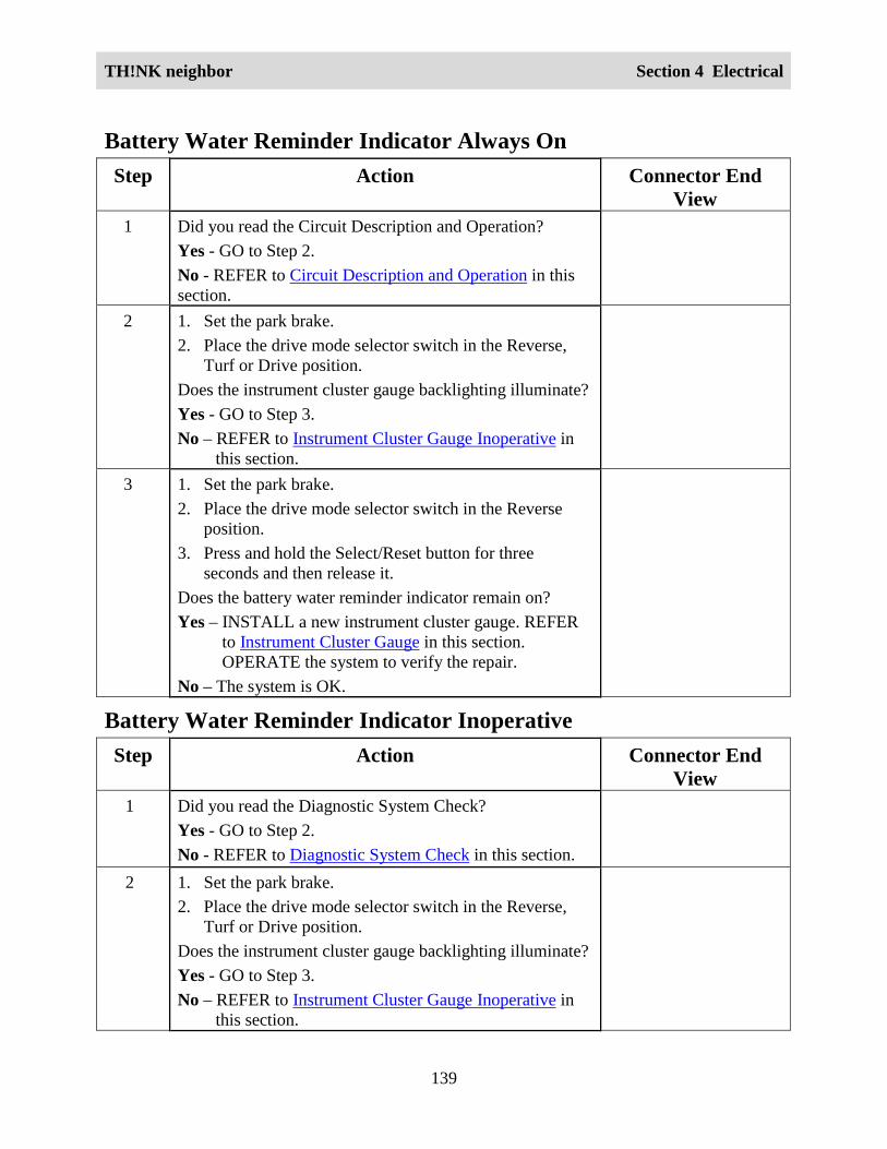
TH!NK neighbor Section 4 Electrical
139
Battery Water Reminder Indicator Always OnStep Action Connector End
View 1 Did you read the Circuit Description and Operation?
Yes - GO to Step 2.No - REFER to Circuit Description and Operation in thissection.
2 1. Set the park brake.2. Place the drive mode selector switch in the Reverse,
Turf or Drive position.Does the instrument cluster gauge backlighting illuminate?Yes - GO to Step 3.No – REFER to Instrument Cluster Gauge Inoperative in
this section. 3 1. Set the park brake.
2. Place the drive mode selector switch in the Reverseposition.
3. Press and hold the Select/Reset button for threeseconds and then release it.
Does the battery water reminder indicator remain on?Yes – INSTALL a new instrument cluster gauge. REFER
to Instrument Cluster Gauge in this section.OPERATE the system to verify the repair.
No – The system is OK.
Battery Water Reminder Indicator InoperativeStep Action Connector End
View1 Did you read the Diagnostic System Check?
Yes - GO to Step 2.No - REFER to Diagnostic System Check in this section.
2 1. Set the park brake.2. Place the drive mode selector switch in the Reverse,
Turf or Drive position.Does the instrument cluster gauge backlighting illuminate?Yes - GO to Step 3.No – REFER to Instrument Cluster Gauge Inoperative in
this section.

TH!NK neighbor Section 4 Electrical
140
Step Action Connector EndView
3 1. Place the drive mode selector switch in the OFFposition.
2. Place the drive mode selector switch in the Reverseposition.
3. Press and hold the Select/Reset button for threeseconds and then release it.
Does the battery water reminder indicator display when thedrive mode selector switch is initially placed in theReverse, Turf or Drive position?Yes – The system is OK.No – GO to Step 4.
4 Verify that the correct battery type is set in the instrumentcluster gauge. Refer to Selecting Battery Type in thissection.Does the battery water reminder indicator display whenflooded battery mode is selected?Yes – The system is OK.No – INSTALL a new instrument cluster gauge. REFER toInstrument Cluster Gauge in this section. OPERATE thesystem to verify the repair.
Electrical Leakage Indicator Always OnWARNING:
THE BATTERY PACK ASSEMBLY CAN DELIVER IN EXCESS OF 72 VOLTS OF DCPOWER. IMPROPER HANDLING OF THE BATTERY PACK CAN RESULT ININJURY OR FATALITY. ONLY AUTHORIZED PERSONNEL TRAINED TO WORKWITH BATTERY PACK COMPONENTS ARE PERMITTED TO HANDLE THEBATTERIES.
WARNING:
THE BATTERY PACK CONTAINS HIGH-VOLTAGE COMPONENTS AND WIRING.HIGH-VOLTAGE INSULATED SAFETY GLOVES AND FACE SHIELD MUST BEWORN WHEN PERFORMING THE FOLLOWING STEPS. FAILURE TO FOLLOWTHIS WARNING MAY RESULT IN SEVERE PERSONAL INJURY OR DEATH.

TH!NK neighbor Section 4 Electrical
141
Step Action Connector EndView
1 Did you read the Circuit Description and Operation?Yes - GO to Step 2.No - REFER to Circuit Description and Operation in thissection.
2 Disconnect the chassis connector and wait for 30 seconds.Does the electrical leakage indicator remain on?Yes – INSTALL a new instrument cluster gauge. REFER
to Instrument Cluster Gauge in this section.OPERATE the system to verify the repair.
No – REFER to Electrical Leakage Detection in thissection.
120VAC Energized Indicator InoperativeStep Action Connector End
View 1 Did you read the Circuit Description and Operation?
Yes - GO to Step 2.No - REFER to Circuit Description and Operation in thissection.
2 1. Place the drive mode selector switch in the OFFposition and remove the key.
2. Connect the GFCI cord to the charger.Does the 120VAC energized indicator display on theinstrument cluster gauge?Yes – GO to Step 3.No – GO to Step 4.
3 Disconnect the GFCI cord from the charger.Does the 120VAC energized indicator remain on?Yes – REFER to 120VAC Energized Indicator Always On
in this section.No – The system is OK.
4 1. Disconnect the charger harness connector.2. Disconnect the instrument cluster gauge harness
connector J7A.3. Connect a DVOM between the charger harness
ChargerInstrument ClusterGauge – J7A

TH!NK neighbor Section 4 Electrical
142
Step Action Connector EndView
connector terminal 3 and the instrument cluster gaugeharness connector J7A terminal 13.
Does continuity exist?Yes – GO to Step 5.No – INSTALL a new 72 volt harness. REFER to WiringHarnesses in this section. OPERATE the system to verifythe repair.
5 1. Reconnect the charger harness connector.2. Connect a DVOM between the instrument cluster
gauge harness connector J7A terminal 13 and thebattery pack positive.
Does the DVOM display approximately 72 volts?Yes – GO to Step 6.No – INSTALL a new charger. REFER to Charger in thissection. OPERATE the system to verify the repair.
Instrument ClusterGauge – J7A
6 1. Connect the GFCI cord to the charger.2. Connect a DVOM between the instrument cluster
gauge connector J7A terminal 13 and the battery packpositive.
Does the DVOM display approximately 0 volts?Yes – INSTALL a new instrument cluster gauge. REFER
to Instrument Cluster Gauge in this section.OPERATE the system to verify the repair.
No – INSTALL a new charger. REFER to Charger in thissection. OPERATE the system to verify the repair.
Instrument ClusterGauge – J7A
120VAC Energized Indicator Always OnStep Action Connector End
View 1 Did you read the Circuit Description and Operation?
Yes - GO to Step 2.
No - REFER to Circuit Description and Operation in thissection.
2 1. Make sure the GFCI cord is not connected to thecharger.
2. Disconnect the instrument cluster gauge harness
Instrument ClusterGauge – J7A
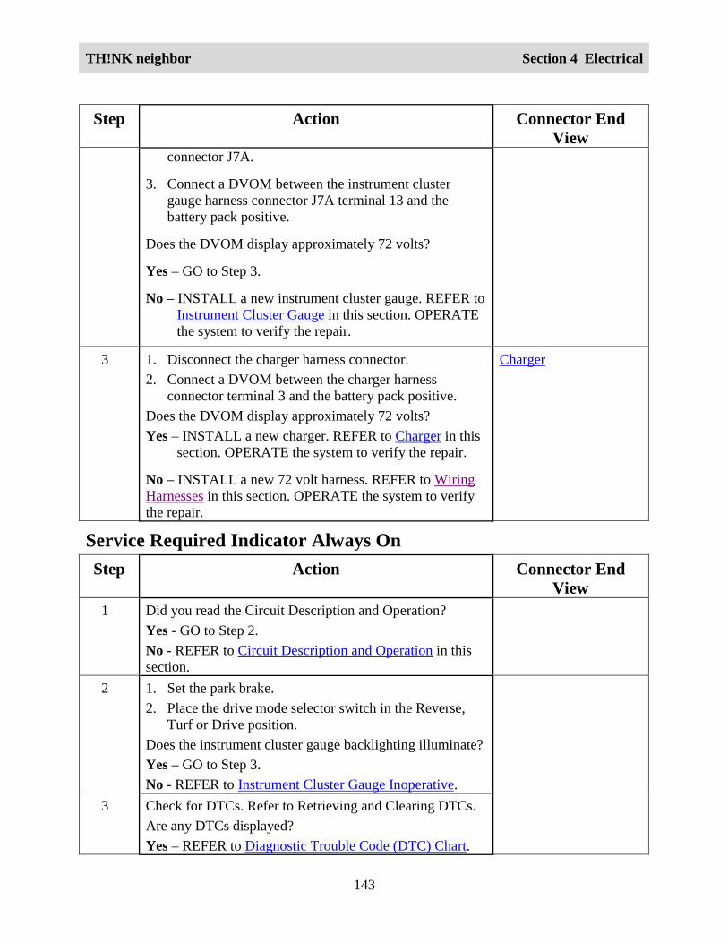
TH!NK neighbor Section 4 Electrical
143
Step Action Connector EndView
connector J7A.
3. Connect a DVOM between the instrument clustergauge harness connector J7A terminal 13 and thebattery pack positive.
Does the DVOM display approximately 72 volts?
Yes – GO to Step 3.
No – INSTALL a new instrument cluster gauge. REFER toInstrument Cluster Gauge in this section. OPERATEthe system to verify the repair.
3 1. Disconnect the charger harness connector.2. Connect a DVOM between the charger harness
connector terminal 3 and the battery pack positive.Does the DVOM display approximately 72 volts?Yes – INSTALL a new charger. REFER to Charger in this
section. OPERATE the system to verify the repair.
No – INSTALL a new 72 volt harness. REFER to WiringHarnesses in this section. OPERATE the system to verifythe repair.
Charger
Service Required Indicator Always OnStep Action Connector End
View 1 Did you read the Circuit Description and Operation?
Yes - GO to Step 2.No - REFER to Circuit Description and Operation in thissection.
2 1. Set the park brake.2. Place the drive mode selector switch in the Reverse,
Turf or Drive position.Does the instrument cluster gauge backlighting illuminate?Yes – GO to Step 3.No - REFER to Instrument Cluster Gauge Inoperative.
3 Check for DTCs. Refer to Retrieving and Clearing DTCs.Are any DTCs displayed?Yes – REFER to Diagnostic Trouble Code (DTC) Chart.
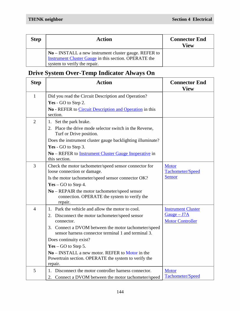
TH!NK neighbor Section 4 Electrical
144
Step Action Connector EndView
No – INSTALL a new instrument cluster gauge. REFER toInstrument Cluster Gauge in this section. OPERATE thesystem to verify the repair.
Drive System Over-Temp Indicator Always OnStep Action Connector End
View 1 Did you read the Circuit Description and Operation?
Yes - GO to Step 2.No - REFER to Circuit Description and Operation in thissection.
2 1. Set the park brake.2. Place the drive mode selector switch in the Reverse,
Turf or Drive position.Does the instrument cluster gauge backlighting illuminate?Yes - GO to Step 3.No – REFER to Instrument Cluster Gauge Inoperative inthis section.
3 Check the motor tachometer/speed sensor connector forloose connection or damage.Is the motor tachometer/speed sensor connector OK?Yes – GO to Step 4.No – REPAIR the motor tachometer/speed sensor
connection. OPERATE the system to verify therepair.
MotorTachometer/SpeedSensor
4 1. Park the vehicle and allow the motor to cool.2. Disconnect the motor tachometer/speed sensor
connector.3. Connect a DVOM between the motor tachometer/speed
sensor harness connector terminal 1 and terminal 3.Does continuity exist?Yes – GO to Step 5.No – INSTALL a new motor. REFER to Motor in thePowertrain section. OPERATE the system to verify therepair.
Instrument ClusterGauge – J7AMotor Controller
5 1. Disconnect the motor controller harness connector.2. Connect a DVOM between the motor tachometer/speed
MotorTachometer/Speed

TH!NK neighbor Section 4 Electrical
145
Step Action Connector EndView
sensor harness connector terminal 1 and the motorcontroller harness connector terminal 21.
Does continuity exist?Yes – GO to Step 6.No – INSTALL a new 72 volt harness. REFER to WiringHarnesses in this section. OPERATE the system to verifythe repair.
Sensor
6 1. Disconnect the instrument cluster gauge connectorJ7A.
2. Connect a DVOM between the motor tachometer/speedsensor harness connector terminal 3 and the instrumentcluster gauge harness connector terminal 10.
Does continuity exist?Yes – INSTALL a new motor controller. REFER to Motor
Controller in the Powertrain section. OPERATE thesystem to verify the repair.
No – INSTALL a new 72 volt harness. REFER to WiringHarnesses in this section. OPERATE the system to verifythe repair.
MotorTachometer/SpeedSensorInstrument ClusterGauge – J7A
Park Brake/Fluid Warning/Rollaway Reminder IndicatorInoperativeWARNING:
THE BATTERY PACK ASSEMBLY CAN DELIVER IN EXCESS OF 72 VOLTS OF DCPOWER. IMPROPER HANDLING OF THE BATTERY PACK CAN RESULT ININJURY OR FATALITY. ONLY AUTHORIZED PERSONNEL TRAINED TO WORKWITH BATTERY PACK COMPONENTS ARE PERMITTED TO HANDLE THEBATTERIES.
WARNING:
THE BATTERY PACK CONTAINS HIGH-VOLTAGE COMPONENTS AND WIRING.HIGH-VOLTAGE INSULATED SAFETY GLOVES AND FACE SHIELD MUST BEWORN WHEN PERFORMING THE FOLLOWING STEPS. FAILURE TO FOLLOWTHIS WARNING MAY RESULT IN SEVERE PERSONAL INJURY OR DEATH.

TH!NK neighbor Section 4 Electrical
146
Step Action Connector EndView
1 Did you read the Circuit Description and Operation?Yes - GO to Step 3.No - REFER to Circuit Description and Operation in thissection..
2 1. Set the park brake.2. Place the drive mode selector switch in the Reverse,
Turf or Drive position.Does the instrument cluster gauge backlighting illuminate?Yes – GO to Step 3.No – REFER to Instrument Cluster Gauge Inoperative inthis section..
3 Make sure the park brake is set.Does the instrument cluster gauge display the parkbrake/fluid warning/rollaway reminder indicator?Yes – GO to Step 4.No - GO to Step 5.
4 With the park brake switch connected, remove the capfrom the brake fluid reservoir.Does the instrument cluster gauge display the parkbrake/fluid warning/rollaway reminder indicator?Yes – The system is OK.No - GO to Step 5.
5 1. Disconnect the instrument cluster gauge harnessconnector J8.
2. Disconnect the park brake switch harness connector.3. Connect a DVOM between the instrument cluster
gauge connector J8 terminal 1 and connector J8terminal 2 and the park brake switch harness connectorterminal 1.
Does continuity exist?Yes – GO to Step 6.No - REPAIR circuit 37. OPERATE the system to verifythe repair.
Instrument ClusterGauge – J8Park Brake Switch
6 Connect a DVOM between the instrument cluster gaugeharness connector J8 terminal 2 and the park brake switchharness connector terminal 2.
Instrument ClusterGauge – J8Park Brake Switch
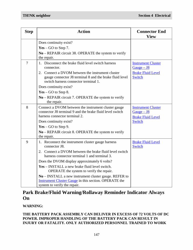
TH!NK neighbor Section 4 Electrical
147
Step Action Connector EndView
Does continuity exist?Yes – GO to Step 7.No – REPAIR circuit 38. OPERATE the system to verifythe repair.
7 1. Disconnect the brake fluid level switch harnessconnector.
2. Connect a DVOM between the instrument clustergauge connector J8 terminal 8 and the brake fluid levelswitch harness connector terminal 1.
Does continuity exist?Yes – GO to Step 8.No – REPAIR circuit 7. OPERATE the system to verify
the repair.
Instrument ClusterGauge – J8Brake Fluid LevelSwitch
8 Connect a DVOM between the instrument cluster gaugeconnector J8 terminal 9 and the brake fluid level switchharness connector terminal 2.Does continuity exist?Yes – GO to Step 9.No – REPAIR circuit 8. OPERATE the system to verifythe repair.
Instrument ClusterGauge – J8Brake Fluid LevelSwitch
9 1. Reconnect the instrument cluster gauge harnessconnector J8.
2. Connect a DVOM between the brake fluid level switchharness connector terminal 1 and terminal 3.
Does the DVOM display approximately 6 volts?Yes – INSTALL a new brake fluid level switch.
OPERATE the system to verify the repair.No – INSTALL a new instrument cluster gauge. REFER toInstrument Cluster Gauge in this section. OPERATE thesystem to verify the repair.
Brake Fluid LevelSwitch
Park Brake/Fluid Warning/Rollaway Reminder Indicator AlwaysOnWARNING:
THE BATTERY PACK ASSEMBLY CAN DELIVER IN EXCESS OF 72 VOLTS OF DCPOWER. IMPROPER HANDLING OF THE BATTERY PACK CAN RESULT ININJURY OR FATALITY. ONLY AUTHORIZED PERSONNEL TRAINED TO WORK

TH!NK neighbor Section 4 Electrical
148
WITH BATTERY PACK COMPONENTS ARE PERMITTED TO HANDLE THEBATTERIES.
WARNING:
THE BATTERY PACK CONTAINS HIGH-VOLTAGE COMPONENTS AND WIRING.HIGH-VOLTAGE INSULATED SAFETY GLOVES AND FACE SHIELD MUST BEWORN WHEN PERFORMING THE FOLLOWING STEPS. FAILURE TO FOLLOWTHIS WARNING MAY RESULT IN SEVERE PERSONAL INJURY OR DEATH.
Step Action Connector EndView
1 Did you read the Circuit Description and Operation?
Yes – GO to Step 3.
No - REFER to Circuit Description and Operation in thissection.
2 1. Set the park brake.
2. Place the drive mode selector switch in the Reverse,Turf or Drive position.
Does the instrument cluster gauge backlightingilluminate?
Yes – GO to Step 3.
No – REFER to Instrument Cluster Gauge Inoperative inthis section.
3 Disconnect the brake fluid level switch harnessconnector.
Does the park brake/fluid warning/rollaway reminderindicator remain on?
Yes – GO to Step 4.
No – INSTALL a new brake fluid level switch.OPERATE the system to verify the repair.
Brake Fluid LevelSwitch
4 Disconnect the park brake switch.
Does the park brake/fluid warning/rollaway reminderindicator remain on?
Yes – GO to Step 5.
No – INSTALL a new park brake switch. OPERATE thesystem to verify the repair.
5 Connect a DVOM between the brake fluid level switch Brake Fluid Level

TH!NK neighbor Section 4 Electrical
149
Step Action Connector EndView
harness connector terminal 1 and terminal 3.
Does the DVOM display approximately 6 volts?
Yes – GO to Step 7.
No – GO to Step 6.
Switch
6 1. Disconnect the instrument cluster gauge harnessconnector J8.
2. Connect a DVOM between the instrument clustergauge harness connector J8 terminal 8 and the brakefluid level switch harness connector terminal 1.
3. Connect a DVOM between the instrument clustergauge harness connector J8 terminal 9 and the brakefluid level switch harness connector terminal 3.
Does continuity exist?
Yes – INSTALL a new instrument cluster gauge. REFERto Instrument Cluster Gauge in this section.OPERATE the system to verify the repair.
No – REPAIR circuit 7 or circuit 8. OPERATE thesystem to verify the repair.
Instrument ClusterGauge – J8Brake Fluid LevelSwitch
7 1. Reconnect the instrument cluster gauge harnessconnector J8.
2. Connect a DVOM between the park brake switchharness connector terminal 1 and terminal 2.
Does the DVOM display approximately 3 volts?
Yes – INSTALL a new instrument cluster gauge. REFERto Instrument Cluster Gauge in this section.OPERATE the system to verify the repair.
No – GO to Step 8.
Park Brake Switch
8 1. Disconnect the instrument cluster gauge harnessconnector J8.
2. Connect a DVOM between the instrument clustergauge harness connector J8 terminal 1 and the parkbrake switch harness connector terminal 1.
3. Connect a DVOM between the instrument clustergauge harness connector J8 terminal 2 and the parkbrake switch harness connector terminal 2.
Instrument ClusterGauge – J8Park Brake Switch

TH!NK neighbor Section 4 Electrical
150
Step Action Connector EndView
Does continuity exist?
Yes – INSTALL a new instrument cluster gauge. REFERto Instrument Cluster Gauge in this section.OPERATE the system to verify the repair.
No – REPAIR circuit 37 or circuit 38. OPERATE thesystem to verify the repair.
Park Brake/ Rollaway Reminder Chime InoperativeStep Action Connector End
View1 Did you read the Circuit Description and Operation?
Yes – GO to Step 2.
No - REFER to Circuit Description and Operation in thissection.
2 1. Set the park brake.
2. Place the drive mode selector switch in the Reverse,Turf or Drive position.
Does the instrument cluster gauge backlightingilluminate?
Yes – GO to Step 3.
No – REFER to Instrument Cluster Gauge Inoperative inthis section.
3 Place the drive mode selector switch in the Reverseposition.
Does the park brake/rollaway reminder chime sound?
Yes – GO to Step 4.
No – INSTALL a new instrument cluster gauge. REFERto Instrument Cluster Gauge in this section. OPERATEthe system to verify the repair.
4 1. Disengage the park brake.
2. Hold the service brake and place the drive modeselector switch in the OFF position.
Does the park brake/rollaway reminder chime sound for
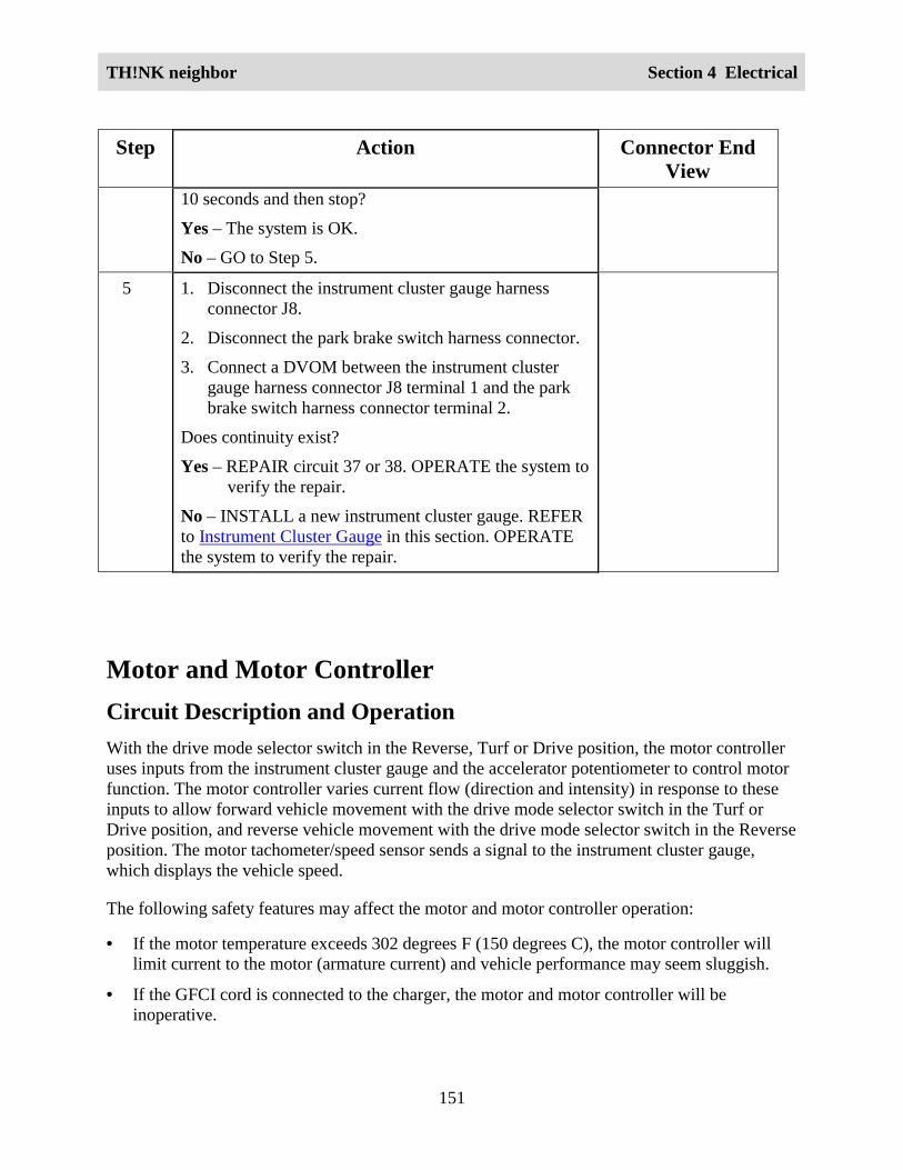
TH!NK neighbor Section 4 Electrical
151
Step Action Connector EndView
10 seconds and then stop?
Yes – The system is OK.
No – GO to Step 5.
5 1. Disconnect the instrument cluster gauge harnessconnector J8.
2. Disconnect the park brake switch harness connector.
3. Connect a DVOM between the instrument clustergauge harness connector J8 terminal 1 and the parkbrake switch harness connector terminal 2.
Does continuity exist?
Yes – REPAIR circuit 37 or 38. OPERATE the system toverify the repair.
No – INSTALL a new instrument cluster gauge. REFERto Instrument Cluster Gauge in this section. OPERATEthe system to verify the repair.
Motor and Motor ControllerCircuit Description and OperationWith the drive mode selector switch in the Reverse, Turf or Drive position, the motor controlleruses inputs from the instrument cluster gauge and the accelerator potentiometer to control motorfunction. The motor controller varies current flow (direction and intensity) in response to theseinputs to allow forward vehicle movement with the drive mode selector switch in the Turf orDrive position, and reverse vehicle movement with the drive mode selector switch in the Reverseposition. The motor tachometer/speed sensor sends a signal to the instrument cluster gauge,which displays the vehicle speed.
The following safety features may affect the motor and motor controller operation:
• If the motor temperature exceeds 302 degrees F (150 degrees C), the motor controller willlimit current to the motor (armature current) and vehicle performance may seem sluggish.
• If the GFCI cord is connected to the charger, the motor and motor controller will beinoperative.

TH!NK neighbor Section 4 Electrical
152
Circuit Schematic

TH!NK neighbor Section 4 Electrical
153

TH!NK neighbor Section 4 Electrical
154

TH!NK neighbor Section 4 Electrical
155
Required ToolsHigh Voltage Insulated Gloves 100-F036 or equivalent
Face Shield 100-F035 or equivalent
System CheckFunctional components in the motor and motor controller system are:
• Service disconnect switch
• Contactor coil
• Control fuse
• Motor
• Motor controller
• Motor tachometer/speed sensor
• Instrument cluster gauge
• Accelerator potentiometer
Guidelines to diagnose the motor and motor controller system:
1. Verify the concern.
2. Check the fuse(s).
3. Check all connectors and related wiring for partially seated terminals, connectors not matingproperly and for dirt, moisture or corrosion. For proper contact, terminal(s) must be free ofall foreign material.
4. Check for any diagnostic trouble codes. Refer to Retrieving and Clearing DTCs.
If the concern still exists, refer to the following table:

TH!NK neighbor Section 4 Electrical
156
Symptom ChartSymptom Possible Causes Action
Incorrect vehicle speed isdisplayed on the instrumentcluster gauge
• Motor tachometer/speedsensor
• Instrument cluster gauge
• Connectors and relatedwiring
GO to Instrument ClusterGauge Does Not DisplayCorrect Vehicle Speed.
Instrument Cluster Gauge Does Not Display Correct Vehicle SpeedWARNING:
THE BATTERY PACK ASSEMBLY CAN DELIVER IN EXCESS OF 72 VOLTS OF DCPOWER. IMPROPER HANDLING OF THE BATTERY PACK CAN RESULT ININJURY OR FATALITY. ONLY AUTHORIZED PERSONNEL TRAINED TO WORKWITH BATTERY PACK COMPONENTS ARE PERMITTED TO HANDLE THEBATTERIES.
WARNING:
THE BATTERY PACK CONTAINS HIGH-VOLTAGE COMPONENTS AND WIRING.HIGH-VOLTAGE INSULATED SAFETY GLOVES AND FACE SHIELD MUST BEWORN WHEN PERFORMING THE FOLLOWING STEPS. FAILURE TO FOLLOWTHIS WARNING MAY RESULT IN SEVERE PERSONAL INJURY OR DEATH.
Step Action Connector EndView
1 Did you read the Circuit Description and Operation?Yes - GO to Step 2.No - REFER to Circuit Description and Operation.
2 1. Raise the vehicle on a hoist.2. Disconnect the motor controller harness connector.3. Connect a fused jumper wire between the motor controller
harness connector terminal 16 and the battery packnegative.
4. Connect a DVOM between the motor controller harnessconnector terminal 16 and terminal 14.
5. Place the drive mode selector switch in the Drive position.6. Slowly rotate both rear vehicle wheels in the same direction.
Motor Controller

TH!NK neighbor Section 4 Electrical
157
Step Action Connector EndView
(This will cause the motor to rotate.)Does the voltage alternate between approximately 1 volt and 10volts?Yes – GO to Step 3.No – GO to Step 5.
3 Observe the instrument cluster gauge while rotating both rearvehicle wheels in the same direction.
Does the speed indication on the instrument cluster gaugechange?
Yes – The system is OK.
No – GO to Step 4.
4 1. Disconnect the instrument cluster gauge harness connectorJ7A.
2. Disconnect the motor tachometer/speed sensor harnessconnector.
3. Connect a DVOM between the instrument cluster connectorJ7A terminal 9 and motor tachometer/speed sensorconnector terminal 6.
Does continuity exist?
Yes – INSTALL a new instrument cluster gauge. REFER toInstrument Cluster Gauge in this section. OPERATE thesystem to verify the repair.
No – REPAIR circuit 31. OPERATE the system to verify therepair.
Instrument ClusterGauge – J7AMotorTachometer/SpeedSensor
5 1. Disconnect the motor tachometer/speed sensor harnessconnector.
2. Connect a DVOM between the motor tachometer/speedsensor harness connector terminal 4 and the battery packnegative.
Does the DVOM display approximately 12 volts?
Yes – GO to Step 6.No – GO to Step 7.
MotorTachometer/SpeedSensor
6 1. Connect a DVOM between the motor controller harnessconnector terminal 16 and the motor tachometer/speedsensor harness connector terminal 5.
Motor ControllerMotorTachometer/Speed
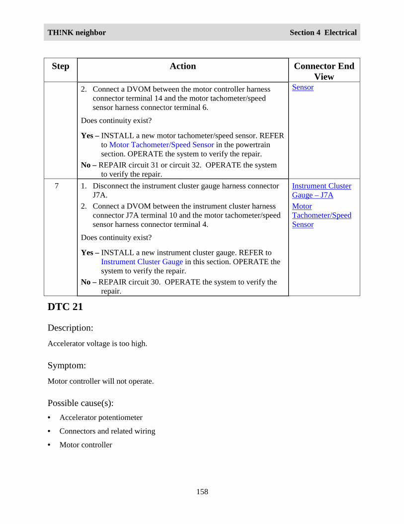
TH!NK neighbor Section 4 Electrical
158
Step Action Connector EndView
2. Connect a DVOM between the motor controller harnessconnector terminal 14 and the motor tachometer/speedsensor harness connector terminal 6.
Does continuity exist?
Yes – INSTALL a new motor tachometer/speed sensor. REFERto Motor Tachometer/Speed Sensor in the powertrainsection. OPERATE the system to verify the repair.
No – REPAIR circuit 31 or circuit 32. OPERATE the systemto verify the repair.
Sensor
7 1. Disconnect the instrument cluster gauge harness connectorJ7A.
2. Connect a DVOM between the instrument cluster harnessconnector J7A terminal 10 and the motor tachometer/speedsensor harness connector terminal 4.
Does continuity exist?
Yes – INSTALL a new instrument cluster gauge. REFER toInstrument Cluster Gauge in this section. OPERATE thesystem to verify the repair.
No – REPAIR circuit 30. OPERATE the system to verify therepair.
Instrument ClusterGauge – J7AMotorTachometer/SpeedSensor
DTC 21
Description:
Accelerator voltage is too high.
Symptom:
Motor controller will not operate.
Possible cause(s):• Accelerator potentiometer
• Connectors and related wiring
• Motor controller

TH!NK neighbor Section 4 Electrical
159
WARNING:
THE BATTERY PACK ASSEMBLY CAN DELIVER IN EXCESS OF 72 VOLTS OF DCPOWER. IMPROPER HANDLING OF THE BATTERY PACK CAN RESULT ININJURY OR FATALITY. ONLY AUTHORIZED PERSONNEL TRAINED TO WORKWITH BATTERY PACK COMPONENTS ARE PERMITTED TO HANDLE THEBATTERIES.
WARNING:
THE BATTERY PACK CONTAINS HIGH-VOLTAGE COMPONENTS AND WIRING.HIGH-VOLTAGE INSULATED SAFETY GLOVES AND FACE SHIELD MUST BEWORN WHEN PERFORMING THE FOLLOWING STEPS. FAILURE TO FOLLOWTHIS WARNING MAY RESULT IN SEVERE PERSONAL INJURY OR DEATH.
Step Action Connector EndView
1. Did you perform the Diagnostic System Check?
Yes - GO to Step 2.
No - REFER to Diagnostic System Check in this section.
2. 1. Disconnect the motor controller harness connector andthe accelerator potentiometer harness connector.
2. Connect a DVOM between the motor controller harnessconnector terminal 7 and the accelerator potentiometerharness connector terminal A.
3. Connect a DVOM between the motor controller harnessconnector terminal 8 and the accelerator potentiometerharness connector terminal E.
4. Connect a DVOM between the motor controller harnessconnector terminal 9 and the accelerator potentiometerharness connector terminal G.
5. Connect a DVOM between the motor controller harnessconnector terminal 13 and the accelerator potentiometerharness connector terminal J.
Does continuity exist?Yes - GO to Step 3.
No – INSTALL a new 72 volt harness. REFER to WiringHarnesses in this section. OPERATE the system toverify the repair.
Motor Controller
AcceleratorPotentiometer
3. Connect a DVOM between the motor controller terminal 7 Motor Controller

TH!NK neighbor Section 4 Electrical
160
Step Action Connector EndView
and the vehicle chassis.
Does the DVOM display greater than approximately 1.25volts?
Yes - INSTALL a new motor controller. REFER to MotorController in the Powertrain section. OPERATE thesystem to verify the repair.
No – INSTALL a new accelerator potentiometer. REFERto Accelerator Potentiometer in the Powertrainsection. OPERATE the system to verify the repair.
DTC 23
Description:
Motor field current is high at start up in the reverse direction.
Symptom:
Motor controller will not operate.
Possible cause(s):• Motor controller.
WARNING:
THE BATTERY PACK ASSEMBLY CAN DELIVER IN EXCESS OF 72 VOLTS OF DCPOWER. IMPROPER HANDLING OF THE BATTERY PACK CAN RESULT ININJURY OR FATALITY. ONLY AUTHORIZED PERSONNEL TRAINED TO WORKWITH BATTERY PACK COMPONENTS ARE PERMITTED TO HANDLE THEBATTERIES.
WARNING:
THE BATTERY PACK CONTAINS HIGH-VOLTAGE COMPONENTS AND WIRING.HIGH-VOLTAGE INSULATED SAFETY GLOVES AND FACE SHIELD MUST BEWORN WHEN PERFORMING THE FOLLOWING STEPS. FAILURE TO FOLLOWTHIS WARNING MAY RESULT IN SEVERE PERSONAL INJURY OR DEATH.
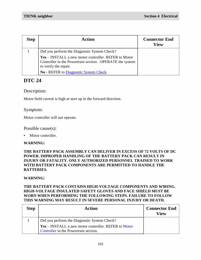
TH!NK neighbor Section 4 Electrical
161
Step Action Connector EndView
1 Did you perform the Diagnostic System Check?Yes – INSTALL a new motor controller. REFER to MotorController in the Powertrain section. OPERATE the systemto verify the repair.No - REFER to Diagnostic System Check.
DTC 24
Description:
Motor field current is high at start up in the forward direction.
Symptom:
Motor controller will not operate.
Possible cause(s):• Motor controller.
WARNING:
THE BATTERY PACK ASSEMBLY CAN DELIVER IN EXCESS OF 72 VOLTS OF DCPOWER. IMPROPER HANDLING OF THE BATTERY PACK CAN RESULT ININJURY OR FATALITY. ONLY AUTHORIZED PERSONNEL TRAINED TO WORKWITH BATTERY PACK COMPONENTS ARE PERMITTED TO HANDLE THEBATTERIES.
WARNING:
THE BATTERY PACK CONTAINS HIGH-VOLTAGE COMPONENTS AND WIRING.HIGH-VOLTAGE INSULATED SAFETY GLOVES AND FACE SHIELD MUST BEWORN WHEN PERFORMING THE FOLLOWING STEPS. FAILURE TO FOLLOWTHIS WARNING MAY RESULT IN SEVERE PERSONAL INJURY OR DEATH.
Step Action Connector EndView
1 Did you perform the Diagnostic System Check?Yes – INSTALL a new motor controller. REFER to MotorController in the Powertrain section.

TH!NK neighbor Section 4 Electrical
162
Step Action Connector EndView
No – REFER to Diagnostic System Check.
DTC 27
Description:
12 volt bus is too low.
Symptom:
Motor controller will not operate.
Possible cause(s):• Motor controller.
WARNING:
THE BATTERY PACK ASSEMBLY CAN DELIVER IN EXCESS OF 72 VOLTS OF DCPOWER. IMPROPER HANDLING OF THE BATTERY PACK CAN RESULT ININJURY OR FATALITY. ONLY AUTHORIZED PERSONNEL TRAINED TO WORKWITH BATTERY PACK COMPONENTS ARE PERMITTED TO HANDLE THEBATTERIES.
WARNING:
THE BATTERY PACK CONTAINS HIGH-VOLTAGE COMPONENTS AND WIRING.HIGH-VOLTAGE INSULATED SAFETY GLOVES AND FACE SHIELD MUST BEWORN WHEN PERFORMING THE FOLLOWING STEPS. FAILURE TO FOLLOWTHIS WARNING MAY RESULT IN SEVERE PERSONAL INJURY OR DEATH.
Step Action Connector EndView
1 Did you perform the Diagnostic System Check?Yes - INSTALL a new motor controller. REFER to Motor
Controller in the Powertrain section. OPERATE thesystem to verify the repair.
No - REFER to Diagnostic System Check.

TH!NK neighbor Section 4 Electrical
163
DTC 41
Description:
Open thermal protector (TP) or transistor over-temperature.
Symptom:
Reduced or no power to traction motor.
Possible cause(s):• Motor controller is in thermal cutback due to high temperature.
• Motor controller.
WARNING:
THE BATTERY PACK ASSEMBLY CAN DELIVER IN EXCESS OF 72 VOLTS OF DCPOWER. IMPROPER HANDLING OF THE BATTERY PACK CAN RESULT ININJURY OR FATALITY. ONLY AUTHORIZED PERSONNEL TRAINED TO WORKWITH BATTERY PACK COMPONENTS ARE PERMITTED TO HANDLE THEBATTERIES.
WARNING:
THE BATTERY PACK CONTAINS HIGH-VOLTAGE COMPONENTS AND WIRING.HIGH-VOLTAGE INSULATED SAFETY GLOVES AND FACE SHIELD MUST BEWORN WHEN PERFORMING THE FOLLOWING STEPS. FAILURE TO FOLLOWTHIS WARNING MAY RESULT IN SEVERE PERSONAL INJURY OR DEATH.
Step Action Connector EndView
1 Did you perform the Diagnostic System Check?Yes - GO to Step 2.No - REFER to Diagnostic System Check.
2 1. Allow the motor to cool to ambient temperature.
2. Clear the DTC. Refer to Retrieving and Clearing DTCs.
3. Drive the vehicle.
4. Check for DTCs. Refer to Retrieving and Clearing DTCs.Does DTC 41 set again?Yes - INSTALL a new motor controller. REFER to Motor

TH!NK neighbor Section 4 Electrical
164
Step Action Connector EndView
Controller in the Powertrain section. OPERATE thesystem to verify the repair.
No – The system is OK.
DTC 42Description:Motor armature offset voltage is too high.
Symptom:
Motor controller will not operate.
Possible cause(s):• Motor controller.
WARNING:
THE BATTERY PACK ASSEMBLY CAN DELIVER IN EXCESS OF 72 VOLTS OF DCPOWER. IMPROPER HANDLING OF THE BATTERY PACK CAN RESULT ININJURY OR FATALITY. ONLY AUTHORIZED PERSONNEL TRAINED TO WORKWITH BATTERY PACK COMPONENTS ARE PERMITTED TO HANDLE THEBATTERIES.
WARNING:
THE BATTERY PACK CONTAINS HIGH-VOLTAGE COMPONENTS AND WIRING.HIGH-VOLTAGE INSULATED SAFETY GLOVES AND FACE SHIELD MUST BEWORN WHEN PERFORMING THE FOLLOWING STEPS. FAILURE TO FOLLOWTHIS WARNING MAY RESULT IN SEVERE PERSONAL INJURY OR DEATH.
Step Action Connector EndView
1 Did you perform the Diagnostic System Check?Yes - INSTALL a new motor controller. REFER to Motor
Controller in the Powertrain section. OPERATE thesystem to verify the repair.
No - REFER to Diagnostic System Check.
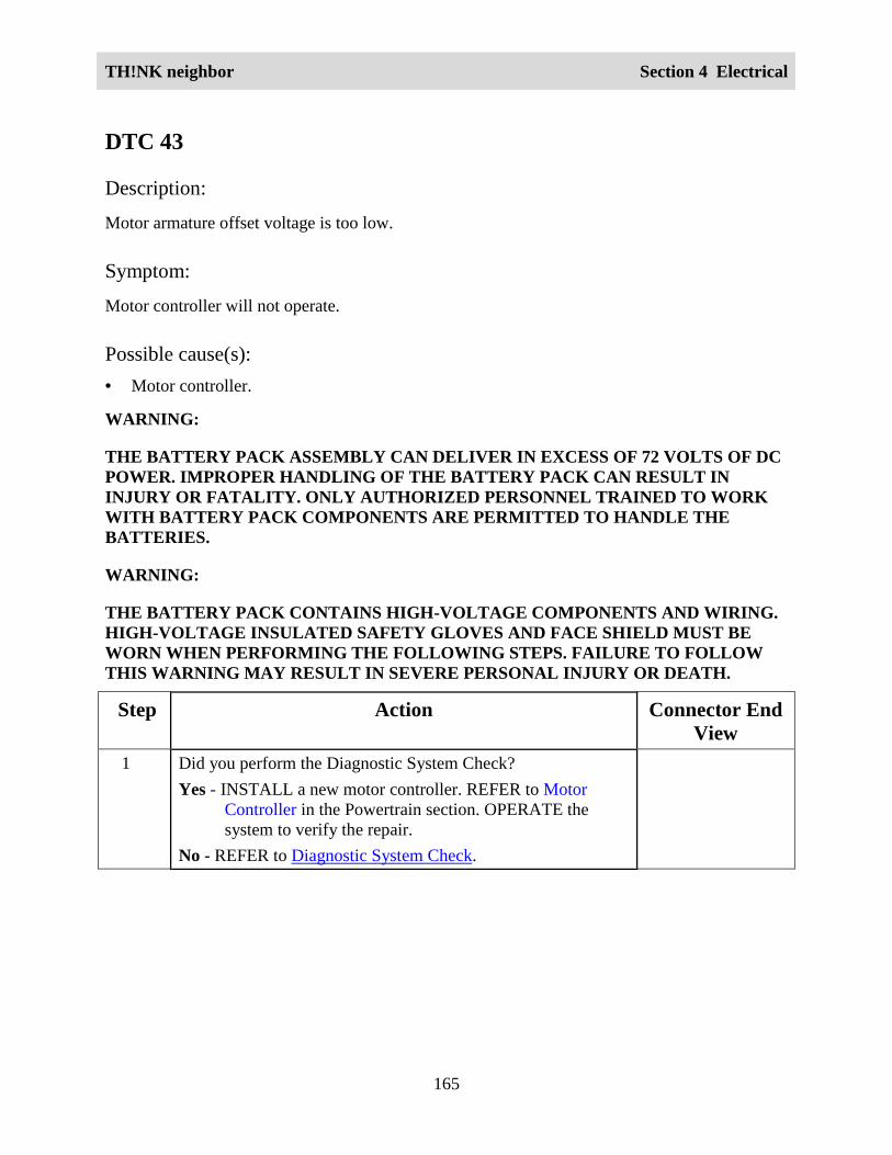
TH!NK neighbor Section 4 Electrical
165
DTC 43
Description:
Motor armature offset voltage is too low.
Symptom:
Motor controller will not operate.
Possible cause(s):• Motor controller.
WARNING:
THE BATTERY PACK ASSEMBLY CAN DELIVER IN EXCESS OF 72 VOLTS OF DCPOWER. IMPROPER HANDLING OF THE BATTERY PACK CAN RESULT ININJURY OR FATALITY. ONLY AUTHORIZED PERSONNEL TRAINED TO WORKWITH BATTERY PACK COMPONENTS ARE PERMITTED TO HANDLE THEBATTERIES.
WARNING:
THE BATTERY PACK CONTAINS HIGH-VOLTAGE COMPONENTS AND WIRING.HIGH-VOLTAGE INSULATED SAFETY GLOVES AND FACE SHIELD MUST BEWORN WHEN PERFORMING THE FOLLOWING STEPS. FAILURE TO FOLLOWTHIS WARNING MAY RESULT IN SEVERE PERSONAL INJURY OR DEATH.
Step Action Connector EndView
1 Did you perform the Diagnostic System Check?Yes - INSTALL a new motor controller. REFER to Motor
Controller in the Powertrain section. OPERATE thesystem to verify the repair.
No - REFER to Diagnostic System Check.

TH!NK neighbor Section 4 Electrical
166
DTC 44
Description:
Armature transistor did not turn off properly.
Symptom:
Motor controller will not operate.
Possible cause(s):• Motor controller.
WARNING:
THE BATTERY PACK ASSEMBLY CAN DELIVER IN EXCESS OF 72 VOLTS OF DCPOWER. IMPROPER HANDLING OF THE BATTERY PACK CAN RESULT ININJURY OR FATALITY. ONLY AUTHORIZED PERSONNEL TRAINED TO WORKWITH BATTERY PACK COMPONENTS ARE PERMITTED TO HANDLE THEBATTERIES.
WARNING:
THE BATTERY PACK CONTAINS HIGH-VOLTAGE COMPONENTS AND WIRING.HIGH-VOLTAGE INSULATED SAFETY GLOVES AND FACE SHIELD MUST BEWORN WHEN PERFORMING THE FOLLOWING STEPS. FAILURE TO FOLLOWTHIS WARNING MAY RESULT IN SEVERE PERSONAL INJURY OR DEATH.
Step Action Connector EndView
1 Did you perform the Diagnostic System Check?Yes - INSTALL a new motor controller. REFER to Motor
Controller in the Powertrain section. OPERATE thesystem to verify the repair.
No - REFER to Diagnostic System Check.

TH!NK neighbor Section 4 Electrical
167
DTC 45
Description:
Armature transistor did not turn on properly.
Symptom:
Motor controller will not operate.
Possible cause(s):• Motor controller.
WARNING:
THE BATTERY PACK ASSEMBLY CAN DELIVER IN EXCESS OF 72 VOLTS OF DCPOWER. IMPROPER HANDLING OF THE BATTERY PACK CAN RESULT ININJURY OR FATALITY. ONLY AUTHORIZED PERSONNEL TRAINED TO WORKWITH BATTERY PACK COMPONENTS ARE PERMITTED TO HANDLE THEBATTERIES.
WARNING:
THE BATTERY PACK CONTAINS HIGH-VOLTAGE COMPONENTS AND WIRING.HIGH-VOLTAGE INSULATED SAFETY GLOVES AND FACE SHIELD MUST BEWORN WHEN PERFORMING THE FOLLOWING STEPS. FAILURE TO FOLLOWTHIS WARNING MAY RESULT IN SEVERE PERSONAL INJURY OR DEATH.
Step Action Connector EndView
1 Did you perform the Diagnostic System Check?Yes - INSTALL a new motor controller. REFER to Motor
Controller in the Powertrain section. OPERATE thesystem to verify the repair.
No - REFER to Diagnostic System Check.

TH!NK neighbor Section 4 Electrical
168
DTC 46
Description:
“Look Ahead” test for A2 voltage is less than 12% of battery voltage.
Symptom:
Motor controller will not operate.
Possible cause(s):• Motor controller.
WARNING:
THE BATTERY PACK ASSEMBLY CAN DELIVER IN EXCESS OF 72 VOLTS OF DCPOWER. IMPROPER HANDLING OF THE BATTERY PACK CAN RESULT ININJURY OR FATALITY. ONLY AUTHORIZED PERSONNEL TRAINED TO WORKWITH BATTERY PACK COMPONENTS ARE PERMITTED TO HANDLE THEBATTERIES.
WARNING:
THE BATTERY PACK CONTAINS HIGH-VOLTAGE COMPONENTS AND WIRING.HIGH-VOLTAGE INSULATED SAFETY GLOVES AND FACE SHIELD MUST BEWORN WHEN PERFORMING THE FOLLOWING STEPS. FAILURE TO FOLLOWTHIS WARNING MAY RESULT IN SEVERE PERSONAL INJURY OR DEATH.
Step Action Connector EndView
1 Did you perform the Diagnostic System Check?Yes – INSTALL a new motor controller. REFER to MotorController in the Powertrain section. OPERATE the system toverify the repair.No - REFER to Diagnostic System Check.

TH!NK neighbor Section 4 Electrical
169
DTC 49
Description:
Motor field current is too low during the run mode.
Symptom:
Motor controller will not operate.
Possible cause(s):• Motor.
• Motor controller.
WARNING:
THE BATTERY PACK ASSEMBLY CAN DELIVER IN EXCESS OF 72 VOLTS OF DCPOWER. IMPROPER HANDLING OF THE BATTERY PACK CAN RESULT ININJURY OR FATALITY. ONLY AUTHORIZED PERSONNEL TRAINED TO WORKWITH BATTERY PACK COMPONENTS ARE PERMITTED TO HANDLE THEBATTERIES.
WARNING:
THE BATTERY PACK CONTAINS HIGH-VOLTAGE COMPONENTS AND WIRING.HIGH-VOLTAGE INSULATED SAFETY GLOVES AND FACE SHIELD MUST BEWORN WHEN PERFORMING THE FOLLOWING STEPS. FAILURE TO FOLLOWTHIS WARNING MAY RESULT IN SEVERE PERSONAL INJURY OR DEATH.
Step Action Connector EndView
1 Did you perform the Diagnostic System Check?Yes - GO to Step 2.No - REFER to Diagnostic System Check.
2 1. Disconnect the motor field connections at the motor.
2. Connect a DVOM between the motor field terminals.
Does continuity exist?Yes - INSTALL a new motor controller. REFER to Motor
Controller in the Powertrain section. OPERATE thesystem to verify the repair.
No – INSTALL a new motor. REFER to Motor in the

TH!NK neighbor Section 4 Electrical
170
Step Action Connector EndView
Powertrain section. OPERATE the system to verify therepair.
DTC 51
Description:
Capacitor voltage is low before the line contactor closes.
Symptom:
Motor controller will not operate.
Possible cause(s):• Motor controller.
WARNING:
THE BATTERY PACK ASSEMBLY CAN DELIVER IN EXCESS OF 72 VOLTS OF DCPOWER. IMPROPER HANDLING OF THE BATTERY PACK CAN RESULT ININJURY OR FATALITY. ONLY AUTHORIZED PERSONNEL TRAINED TO WORKWITH BATTERY PACK COMPONENTS ARE PERMITTED TO HANDLE THEBATTERIES.
WARNING:
THE BATTERY PACK CONTAINS HIGH-VOLTAGE COMPONENTS AND WIRING.HIGH-VOLTAGE INSULATED SAFETY GLOVES AND FACE SHIELD MUST BEWORN WHEN PERFORMING THE FOLLOWING STEPS. FAILURE TO FOLLOWTHIS WARNING MAY RESULT IN SEVERE PERSONAL INJURY OR DEATH.
Step Action Connector EndView
1 Did you perform the Diagnostic System Check?Yes - INSTALL a new motor controller. REFER to Motor
Controller in the Powertrain section. OPERATE thesystem to verify the repair.
No - REFER to Diagnostic System Check.
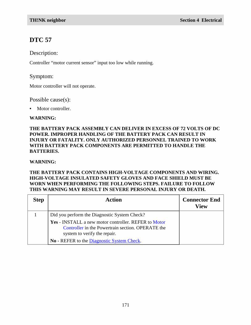
TH!NK neighbor Section 4 Electrical
171
DTC 57
Description:
Controller “motor current sensor” input too low while running.
Symptom:
Motor controller will not operate.
Possible cause(s):• Motor controller.
WARNING:
THE BATTERY PACK ASSEMBLY CAN DELIVER IN EXCESS OF 72 VOLTS OF DCPOWER. IMPROPER HANDLING OF THE BATTERY PACK CAN RESULT ININJURY OR FATALITY. ONLY AUTHORIZED PERSONNEL TRAINED TO WORKWITH BATTERY PACK COMPONENTS ARE PERMITTED TO HANDLE THEBATTERIES.
WARNING:
THE BATTERY PACK CONTAINS HIGH-VOLTAGE COMPONENTS AND WIRING.HIGH-VOLTAGE INSULATED SAFETY GLOVES AND FACE SHIELD MUST BEWORN WHEN PERFORMING THE FOLLOWING STEPS. FAILURE TO FOLLOWTHIS WARNING MAY RESULT IN SEVERE PERSONAL INJURY OR DEATH.
Step Action Connector EndView
1 Did you perform the Diagnostic System Check?Yes - INSTALL a new motor controller. REFER to Motor
Controller in the Powertrain section. OPERATE thesystem to verify the repair.
No - REFER to the Diagnostic System Check.

TH!NK neighbor Section 4 Electrical
172
DTC 66
Description:
The field current exceeds the current limit of the field transistor.
Symptom:
Control will not operate or is sluggish on start up. Line contactor opens.
Possible cause(s):• Motor field circuits shorted.
• Binding line contactor.
• Motor over-temperature condition.
• Motor thermal fuse.
• Motor controller.
WARNING:
THE BATTERY PACK ASSEMBLY CAN DELIVER IN EXCESS OF 72 VOLTS OF DCPOWER. IMPROPER HANDLING OF THE BATTERY PACK CAN RESULT ININJURY OR FATALITY. ONLY AUTHORIZED PERSONNEL TRAINED TO WORKWITH BATTERY PACK COMPONENTS ARE PERMITTED TO HANDLE THEBATTERIES.
WARNING:
THE BATTERY PACK CONTAINS HIGH-VOLTAGE COMPONENTS AND WIRING.HIGH-VOLTAGE INSULATED SAFETY GLOVES AND FACE SHIELD MUST BEWORN WHEN PERFORMING THE FOLLOWING STEPS. FAILURE TO FOLLOWTHIS WARNING MAY RESULT IN SEVERE PERSONAL INJURY OR DEATH.
Step Action Connector EndView
1. Did you perform the Diagnostic System Check?Yes – GO to Step 2.No - REFER to the Diagnostic System Check.
2. 1. Disconnect the motor field connections at the motor.
2. Connect a DVOM between the motor field terminals.
Does the DVOM display approximately 1.3 ohms?
Motor

TH!NK neighbor Section 4 Electrical
173
Step Action Connector EndView
Yes – GO to Step 3.No – INSTALL a new motor. REFER to Motor in the
Powertrain section. OPERATE the system to verify therepair.
3. 1. Disconnect the motor field connections at the motorcontroller.
2. Connect a DVOM between motor F1 and motor controllerF1.
3. Connect a DVOM between motor F2 and motor controllerF2.
Does continuity exist?
Yes – GO to Step 4.
No – REPAIR open in field cable. OPERATE the system toverify the repair.
4. 1. Connect a DVOM between motor F1 and the vehiclechassis.
2. Connect a DVOM between motor F2 and the vehiclechassis.
Does continuity exist?
Yes – REPAIR field cable short to ground. OPERATE thesystem to verify the repair.
No – INSTALL a new motor controller. REFER to MotorController in the Powertrain section. OPERATE thesystem to verify the repair.

TH!NK neighbor Section 4 Electrical
174
DTC 76
Description:
Capacitor 1C voltage too high during regenerative braking.
Symptom:
Motor controller will not operate.
Possible cause(s):• Motor controller.
WARNING:
THE BATTERY PACK ASSEMBLY CAN DELIVER IN EXCESS OF 72 VOLTS OF DCPOWER. IMPROPER HANDLING OF THE BATTERY PACK CAN RESULT ININJURY OR FATALITY. ONLY AUTHORIZED PERSONNEL TRAINED TO WORKWITH BATTERY PACK COMPONENTS ARE PERMITTED TO HANDLE THEBATTERIES.
WARNING:
THE BATTERY PACK CONTAINS HIGH-VOLTAGE COMPONENTS AND WIRING.HIGH-VOLTAGE INSULATED SAFETY GLOVES AND FACE SHIELD MUST BEWORN WHEN PERFORMING THE FOLLOWING STEPS. FAILURE TO FOLLOWTHIS WARNING MAY RESULT IN SEVERE PERSONAL INJURY OR DEATH.
Step Action Connector EndView
1. Did you perform the Diagnostic System Check?Yes - INSTALL a new motor controller. REFER to Motor
Controller in the Powertrain section. OPERATE thesystem to verify the repair.
No - REFER to the Diagnostic System Check.
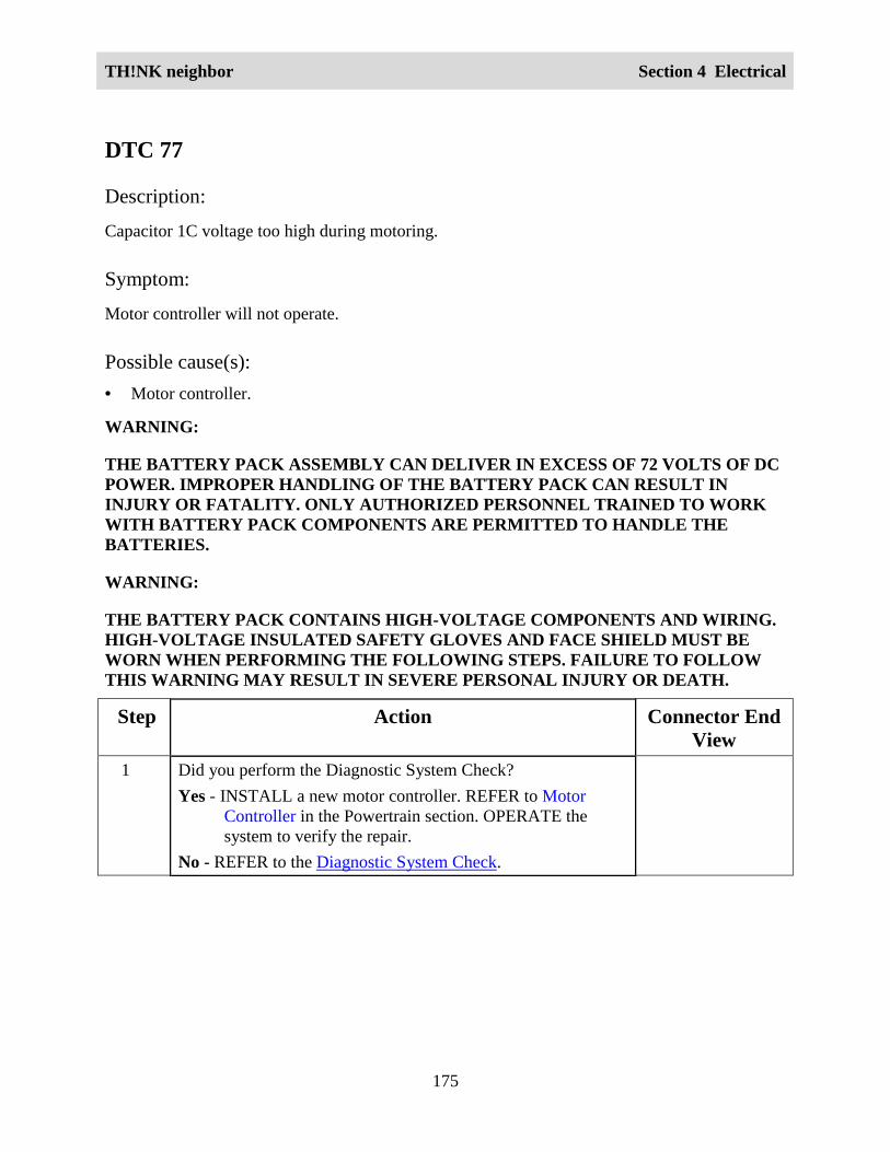
TH!NK neighbor Section 4 Electrical
175
DTC 77
Description:
Capacitor 1C voltage too high during motoring.
Symptom:
Motor controller will not operate.
Possible cause(s):• Motor controller.
WARNING:
THE BATTERY PACK ASSEMBLY CAN DELIVER IN EXCESS OF 72 VOLTS OF DCPOWER. IMPROPER HANDLING OF THE BATTERY PACK CAN RESULT ININJURY OR FATALITY. ONLY AUTHORIZED PERSONNEL TRAINED TO WORKWITH BATTERY PACK COMPONENTS ARE PERMITTED TO HANDLE THEBATTERIES.
WARNING:
THE BATTERY PACK CONTAINS HIGH-VOLTAGE COMPONENTS AND WIRING.HIGH-VOLTAGE INSULATED SAFETY GLOVES AND FACE SHIELD MUST BEWORN WHEN PERFORMING THE FOLLOWING STEPS. FAILURE TO FOLLOWTHIS WARNING MAY RESULT IN SEVERE PERSONAL INJURY OR DEATH.
Step Action Connector EndView
1 Did you perform the Diagnostic System Check?Yes - INSTALL a new motor controller. REFER to Motor
Controller in the Powertrain section. OPERATE thesystem to verify the repair.
No - REFER to the Diagnostic System Check.

TH!NK neighbor Section 4 Electrical
176
DTC 90
Description:
Motor thermostat is open during control operation.
Symptom:
• Over-temp condition has occurred.
• Motor armature current is limited to 100 amps. Vehicle performance is sluggish.
Possible cause(s):
• Motor controller.
• 72 volt harness open.
• Motor over-temperature condition.
• Motor thermal fuse (internal to the motor).
• Instrument cluster gauge.
WARNING:
THE BATTERY PACK ASSEMBLY CAN DELIVER IN EXCESS OF 72 VOLTS OF DCPOWER. IMPROPER HANDLING OF THE BATTERY PACK CAN RESULT ININJURY OR FATALITY. ONLY AUTHORIZED PERSONNEL TRAINED TO WORKWITH BATTERY PACK COMPONENTS ARE PERMITTED TO HANDLE THEBATTERIES.
WARNING:
THE BATTERY PACK CONTAINS HIGH-VOLTAGE COMPONENTS AND WIRING.HIGH-VOLTAGE INSULATED SAFETY GLOVES AND FACE SHIELD MUST BEWORN WHEN PERFORMING THE FOLLOWING STEPS. FAILURE TO FOLLOWTHIS WARNING MAY RESULT IN SEVERE PERSONAL INJURY OR DEATH.
Step Action Connector EndView
1 Did you perform the Diagnostic System Check?Yes - GO to Step 2.No - REFER to Diagnostic System Check.
2 1. Allow the motor to cool to ambient temperature.

TH!NK neighbor Section 4 Electrical
177
Step Action Connector EndView
2. Clear the DTC. Refer to Retrieving and Clearing DTCs.
3. Drive the vehicle.
4. Check for DTCs. Refer to Retrieving and Clearing DTCs.
Does DTC 90 display again?Yes - GO to Step 3.No – The system is OK.
3 1. Disconnect the motor tachometer/speed sensor harnessconnector.
2. Connect a DVOM between the motor tachometer/speedsensor harness connector terminal 1 and terminal 3.
Does continuity exist?Yes – GO to Step 4.No – INSTALL a new motor. REFER to Motor in thePowertrain section. OPERATE the system to verify the repair.
MotorTachometer/SpeedSensor
4 1. Set the park brake.
2. Place the drive mode selector switch in the Drive position.
3. Connect a DVOM between the motor tachometer/speedsensor harness connector terminal 3 and the battery packnegative.
Does the DVOM display approximately 12 volts?Yes – GO to Step 5.No – GO to Step 6.
MotorTachometer/SpeedSensor
5 1. Disconnect the motor controller harness connector.
2. Connect a DVOM between the motor controller harnessconnector terminal 21 and the motor tachometer/speedsensor connector terminal 1.
Does continuity exist?Yes – INSTALL a new motor controller. REFER to Motor
Controller in the Powertrain section. OPERATE thesystem to verify the repair.
No – REPAIR circuit 73. OPERATE the system to verify therepair.
Motor ControllerMotorTachometer/SpeedSensor
6 1. Place the drive mode selector switch in the OFFposition.
Instrument ClusterGauge – J7A

TH!NK neighbor Section 4 Electrical
178
Step Action Connector EndView
2. Disconnect the instrument cluster gauge harnessconnector J7A.
3. Connect a DVOM between the instrument cluster gaugeharness connector J7A terminal 10 and the motortachometer/speed sensor harness connector terminal 3.
Does continuity exist?Yes – INSTALL a new instrument cluster gauge. REFER to
Instrument Cluster Gauge in this section. OPERATE thesystem to verify the repair.
No – REPAIR circuit 30. OPERATE the system to verify therepair.
MotorTachometer/SpeedSensor
Power PointCircuit Description and Operation72 volt power is applied through the DC/DC fuse to DC/DC converter 2 (optional), then throughthe power point fuse to the power point. The 12 volt return for the power point is also providedthrough the DC/DC converter 2 (optional). When an accessory is inserted into the power point,the circuit is complete and power is applied to the accessory.

TH!NK neighbor Section 4 Electrical
179
Circuit Schematic

TH!NK neighbor Section 4 Electrical
180
Required ToolsHigh Voltage Insulated Gloves 100-F036 or equivalent
Face Shield 100-F035 or equivalent
System CheckFunctional components in the power point system are:
• DC/DC fuse
• DC/DC converter 2 (optional)
• Power point fuse
• Power point
• Related wiring
Guidelines to diagnose the power point system:
1. Verify the concern.
2. Check the fuse(s).
3. Check all connectors and related wiring for partially seated terminals, connectors not matingproperly and for dirt, moisture or corrosion. For proper contact, terminal(s) must be free ofall foreign material.
If the concern still exists, refer to the following table:
Symptom ChartSymptom Possible Causes Action
The power point is inoperative • DC/DC fuse
• Power point fuse
• Power point
• DC/DC converter 2 (optional)
• Connectors or related wiring
GO to Power PointInoperative.

TH!NK neighbor Section 4 Electrical
181
Power Point InoperativeWARNING:
THE BATTERY PACK ASSEMBLY CAN DELIVER IN EXCESS OF 72 VOLTS OF DCPOWER. IMPROPER HANDLING OF THE BATTERY PACK CAN RESULT ININJURY OR FATALITY. ONLY AUTHORIZED PERSONNEL TRAINED TO WORKWITH BATTERY PACK COMPONENTS ARE PERMITTED TO HANDLE THEBATTERIES.
WARNING:
THE BATTERY PACK CONTAINS HIGH-VOLTAGE COMPONENTS AND WIRING.HIGH-VOLTAGE INSULATED SAFETY GLOVES AND FACE SHIELD MUST BEWORN WHEN PERFORMING THE FOLLOWING STEPS. FAILURE TO FOLLOWTHIS WARNING MAY RESULT IN SEVERE PERSONAL INJURY OR DEATH.
Step Action Connector EndView
1 Did you read the Circuit Description and Operation?
Yes - GO to Step 2.
No - REFER to Circuit Description and Operation.
2 Connect a DVOM between the DC/DC converter 2(optional) harness connector terminal 1 and terminal 2.
Does the DVOM display approximately 12 volts?
Yes – GO to Step 3.
No - GO to Step 5.
DC/DC Converter 2(optional)
3 1. Disconnect the power point harness connector.
2. Connect a DVOM between the power point harnessconnector terminal 1 and terminal 2.
Does the DVOM display approximately 12 volts?
Yes – INSTALL a new power point. OPERATE thesystem to verify the repair.
No - GO to Step 4.
DC/DC Converter 2(optional)
4 Connect a DVOM between the DC/DC converter 2(optional) harness connector terminal 1 and the powerpoint harness connector terminal 2.
DC/DC Converter 2(optional)
Power Point

TH!NK neighbor Section 4 Electrical
182
Step Action Connector EndView
Does continuity exist?
Yes – REPAIR circuit 65. OPERATE the system to verifythe repair.
No - REPAIR circuit 57. OPERATE the system to verifythe repair.
5 1. Place the service disconnect switch in the OFFposition.
2. Disconnect the DC/DC converter 2 (optional) harnessconnector.
3. Connect a DVOM between the DC/DC converter 2(optional) harness connector terminal 3 and terminal 4.
4. Place the service disconnect switch in the ON position.
Does the DVOM display approximately 72 volts?
Yes – INSTALL a new DC/DC converter 2 (optional).REFER to DC/DC Converter 2 (Optional) in this section.OPERATE the system to verify the repair.
No – GO to Step 6.
DC/DC Converter 2(optional)
6 Check continuity between the DC/DC converter 2(optional) harness connector terminal 3 and the batterypack negative.
Does continuity exist?
Yes - REPAIR circuit 43. OPERATE the system to verifythe repair.
No – REPAIR circuit 4. OPERATE the system to verifythe repair.
DC/DC Converter 2(optional)

TH!NK neighbor Section 4 Electrical
183
Wiper/WasherCircuit Description and OperationThis is a conventional single speed wiper system. When the drive mode selector switch is in theReverse, Turf or Drive position, 12 volt power is supplied from the DC/DC converter 1(standard) through the DC/DC relay to the wiper/washer fuse. The 12 volt return for the wipermotor is provided through DC/DC converter 1 (standard). When the wiper switch is turned ON,12 volt power is supplied through the multifunction switch to the wiper motor. When the wiperswitch is turned OFF, the wiper motor returns the wiper to the park position. When the washerswitch is held in the ON position, the washer pump operates. The wiper switch must be in theON position for the washer to operate.

TH!NK neighbor Section 4 Electrical
184
Circuit Schematic
TH!NK neighbor Section 4 Electrical
185
System CheckFunctional components in the wiper/washer system are:
• Wiper/washer fuse
• Multifunction switch
• Instrument cluster gauge
• Washer motor
• Wiper motor
• Related wiring
Guidelines to diagnose the wiper/washer system:
1. Verify the concern.
2. Check the fuse(s).
3. Check all connectors and related wiring for partially seated terminals, connectors not matingproperly and for dirt, moisture or corrosion. For proper contact, terminal(s) must be free ofall foreign material.
4. Fill washer fluid as necessary.
5. Check washer hoses/nozzles for obstruction.
If the concern still exists, refer to the following table:

TH!NK neighbor Section 4 Electrical
186
Symptom ChartSymptom Possible Causes Action
The washer is inoperative • Wiper/washer fuse
• Washer motor
• Multifunction switch
• Connectors or relatedwiring
GO to Washer Inoperative.
The wiper is inoperative • Wiper/washer fuse
• Wiper motor
• Connectors or relatedwiring
GO to Wiper Inoperative.
The wiper is always on • Multifunction switch
• Wiper motor
• Connectors or relatedwiring
GO to Wiper Always On.
The wiper does not stop inthe park position
• Wiper motor INSTALL a new wipermotor. REFER to WiperMotor in this section.OPERATE the system toverify the repair.

TH!NK neighbor Section 4 Electrical
187
Washer InoperativeStep Action Connector End
View1 Did you read the Circuit Description and Operation?
Yes – GO to Step 2.
No – REFER to Circuit Description and Operation.
2 1. Disconnect the washer motor harness connector.
2. Set the park brake.
3. Place the drive mode selector switch in the Reverse, Turf orDrive position.
4. Connect a DVOM between the washer motor harnessconnector terminal 1 and terminal 2.
5. Place the wiper switch in the ON position.
6. Press the washer motor switch.
Does the DVOM display approximately 12 volts?
Yes – INSTALL a new washer motor. OPERATE the system toverify the repair.
No – GO to Step 3.
Washer Motor
3 1. Disconnect the multifunction switch harness connector W.
2. Connect a DVOM between the multifunction switch harnessconnector W terminal 4 and the vehicle chassis.
Does the DVOM display approximately 12 volts?
Yes – GO to Step 4.
No – REPAIR circuit 69. OPERATE the system to verify therepair.
MultifunctionSwitch-W
4 1. Check continuity between the washer motor harnessconnector terminal 1 and the multifunction switch harnessconnector W terminal 1.
2. Check continuity between the washer motor harnessconnector terminal 2 and the multifunction switch harnessconnector W terminal 2.
Does continuity exist?
Yes – INSTALL a new multifunction switch. REFER toMultifunction Switch in this section. OPERATE the
Washer Motor
MultifunctionSwitch-W

TH!NK neighbor Section 4 Electrical
188
Step Action Connector EndView
system to verify the repair.
No – REPAIR circuit 5 or circuit 74. OPERATE the system toverify the repair.
Wiper InoperativeStep Action Connector End
View1 Did you read the Circuit Description and Operation?
Yes – GO to Step 2.
No – REFER to Circuit Description and Operation.
2 1. Disconnect the wiper motor harness connector.
2. Set the park brake.
3. Place the drive mode selector switch in the Reverse, Turf orDrive position.
4. Connect a DVOM between the wiper motor harnessconnector terminal 3 and the vehicle chassis.
5. Place the wiper switch in the ON position.
Does the DVOM display approximately 12 volts?
Yes – GO to Step 3.
No – GO to Step 4.
Wiper Motor
3 Check continuity between the wiper motor harness connectorterminal 1 and the vehicle chassis.
Does continuity exist?
Yes – INSTALL a new wiper motor. REFER to Wiper Motor inthis section. OPERATE the system to verify the repair.
No – REPAIR circuit 57. OPERATE the system to verify therepair.
Wiper Motor
4 1. Disconnect the multifunction switch harness connector W.
2. Connect a DVOM between the multifunction switch harnessconnector W terminal 4 and the vehicle chassis.
Does the DVOM display approximately 12 volts?
Yes – GO to Step 5.
MultifunctionSwitch-W

TH!NK neighbor Section 4 Electrical
189
Step Action Connector EndView
No – GO to Step 6.
5 Check continuity between the multifunction switch harnessconnector W terminal 10 and the wiper motor harnessconnector terminal 3.
Does continuity exist?
Yes – INSTALL a new wiper motor. REFER to Wiper Motor inthis section. OPERATE the system to verify the repair.
No – REPAIR circuit 29. OPERATE the system to verify therepair.
MultifunctionSwitch-W
Wiper Motor
6 1. Remove the wiper/washer fuse from the fuse holder.
2. Connect a DVOM between the multifunction switch harnessconnector W terminal 4 and the wiper/washer fuse holderterminal 2.
Does continuity exist?
Yes – REFER to DC/DC Relay Test.
No – REPAIR circuit 69. OPERATE the system to verify therepair.
MultifunctionSwitch-W
Wiper Always OnStep Action Connector End
View1 Did you read the Circuit Description and Operation?
Yes – GO to Step 2.
No – REFER to Circuit Description and Operation.
2 1. Disconnect the multifunction switch harness connector W.
2. Check operation of the wiper motor.
Does the wiper motor continue to operate?
Yes – REPAIR circuit 29 between the multifunction switch andthe wiper motor. OPERATE the system to verify therepair.
No – GO to Step 3.
3 Check continuity between the multifunction switch harnessconnector W terminal 4 and the multifunction switch harness
MultifunctionSwitch-W

TH!NK neighbor Section 4 Electrical
190
Step Action Connector EndView
connector W terminal 10 with the wiper switch in the OFFposition.
Does continuity exist?
Yes – INSTALL a new multifunction switch. REFER toMultifunction Switch in this section. OPERATE thesystem to verify the repair.
No – INSTALL a new wiper motor. REFER to Wiper Motor inthis section. OPERATE the system to verify the repair.

TH!NK neighbor Section 4 Electrical
191
Connector End Views• Accelerator Potentiometer • Battery Temperature Sensor
• Brake Fluid Level Switch • Brake Switch
• Charger • CHMSL/Reverse Lamp
• Contactor Coil • DC/DC Converter 1 (Standard)
• DC/DC Converter 2 (Optional) • DC/DC Relay
• Electronic Flasher • Fuse, Horn/Flasher/Brake
• Fuse, Lights • Fuse, Power Point
• Fuse, Wiper/Washer • Headlamp LH
• Headlamp RH • Heater/Defogger Contactor
• Heater/Defogger (Fan) • Heater/Defogger (Heater)
• Heater/Defogger Inline • Heater/Defogger Switch
• Horn Relay • Instrument Cluster Gauge – J7A
• Instrument Cluster Gauge – J8 • Key Switch
• Motor Controller • Motor Tachometer/Speed Sensor
• Multifunction Switch – L • Multifunction Switch – W
• Power Point • Taillamp LH
• Taillamp RH • Turn Signal LF
• Turn Signal LR • Turn Signal RF
• Turn Signal RR • Washer Motor
• Wiper Motor • 72 Volt Inline
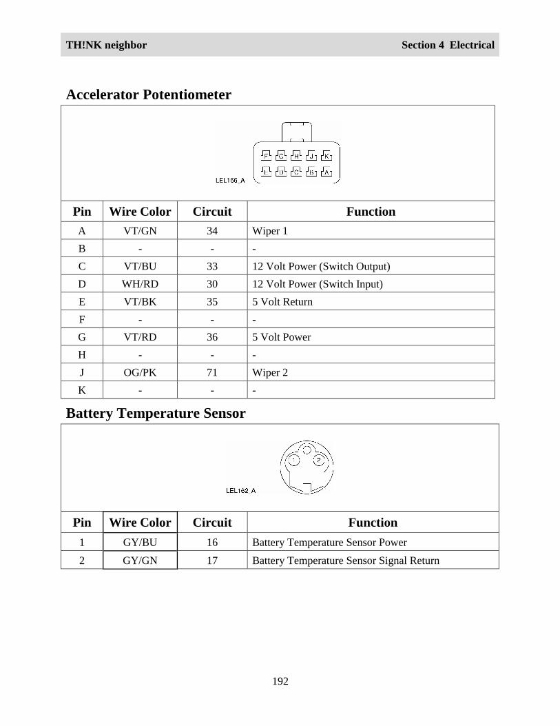
TH!NK neighbor Section 4 Electrical
192
Accelerator Potentiometer
Pin Wire Color Circuit FunctionA VT/GN 34 Wiper 1B - - -C VT/BU 33 12 Volt Power (Switch Output)D WH/RD 30 12 Volt Power (Switch Input)E VT/BK 35 5 Volt ReturnF - - -G VT/RD 36 5 Volt PowerH - - -J OG/PK 71 Wiper 2K - - -
Battery Temperature Sensor
Pin Wire Color Circuit Function1 GY/BU 16 Battery Temperature Sensor Power
2 GY/GN 17 Battery Temperature Sensor Signal Return

TH!NK neighbor Section 4 Electrical
193
Brake Fluid Level Switch
Pin Wire Color Circuit Function1 BU/GY 7 Brake Fluid Level Switch Power
2 - - -
3 YE/GY 8 Brake Fluid Level Switch Signal Return
Brake Switch
Pin Wire Color Circuit Function1 RD/ GN 6 12 Volt Power
2 - - -
3 BU/BK 22 Brake Switch Signal Return

TH!NK neighbor Section 4 Electrical
194
Charger
Pin Wire Color Circuit Function1 OG/GY 11 72 Volt Power
2 OG/BK 4 72 Volt Return
3 GN/BK 67 Charger Inhibit
4 GY/BU 16 Battery Temperature Sensor Power
5 GY/GN 17 Battery Temperature Sensor Signal Return
6 BU/OG 51 Battery Type Select
7 - - -8 - - -
9 - - -
CHMSL/Reverse Lamp
Pin Wire Color Circuit Function1 BU/RD 68 Reverse Lamp Power
2 BU/BK 22 Brake Lamp Power
3 BK 57 CHMSL/Reverse Lamp Return

TH!NK neighbor Section 4 Electrical
195
Contactor
Pin Wire Color Circuit Function1 BK/GN 39 Contactor Return (Coil)
2 OG/VT 41 Contactor Power (Coil)
DC/DC Converter 1 (Standard)
Pin Wire Color Circuit Function1 BK 57 12 Volt Return
2 RD/BU 55 12 Volt Power
3 OG/BK 4 72 Volt Return
4 OG/YE 43 72 Volt Power
DC/DC Converter 2 (Optional)
Pin Wire Color Circuit Function1 BK 57 12 Volt Return
2 RD/BU 55 12 Volt Power
3 OG/BK 4 72 Volt Return
4 OG/YE 43 72 Volt Power

TH!NK neighbor Section 4 Electrical
196
DC/DC Relay
Pin Wire Color Circuit Function1 RD/BU 55 12 Volt Power (Switch)
2 RD/BU 55 12 Volt Power (Coil)
3 - - -
4 BN/RD 79 12 Volt Power (Switched)
5 GY/WH 66 12 Volt Return (Coil)
Drive Mode Selector Switch – J5
Pin Wire Color Circuit Function1 - - 12 Volt Power2 - - Reverse3 - - Turf4 - - Drive
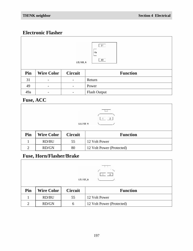
TH!NK neighbor Section 4 Electrical
197
Electronic Flasher
Pin Wire Color Circuit Function31 - - Return49 - - Power49a - - Flash Output
Fuse, ACC
Pin Wire Color Circuit Function1 RD/BU 55 12 Volt Power
2 RD/GN 80 12 Volt Power (Protected)
Fuse, Horn/Flasher/Brake
Pin Wire Color Circuit Function1 RD/BU 55 12 Volt Power
2 RD/GN 6 12 Volt Power (Protected)

TH!NK neighbor Section 4 Electrical
198
Fuse, Lights
Pin Wire Color Circuit Function1 BN/RD 79 12 Volt Power
2 RD/GY 69 12 Volt Power (Protected)
Fuse, Power Point
Pin Wire Color Circuit Function1 RD/WH 65 12 Volt Power (Protected)
2 RD/WH 65 12 Volt Power
Fuse, Wiper/Washer
Pin Wire Color Circuit Function1 BN/RD 79 12 Volt Power
2 RD/GY 69 12 Volt Power (Protected)
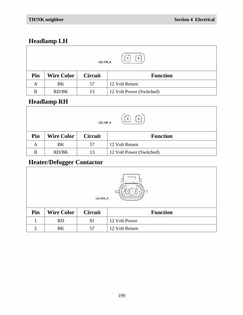
TH!NK neighbor Section 4 Electrical
199
Headlamp LH
Pin Wire Color Circuit FunctionA BK 57 12 Volt ReturnB RD/BK 13 12 Volt Power (Switched)
Headlamp RH
Pin Wire Color Circuit FunctionA BK 57 12 Volt ReturnB RD/BK 13 12 Volt Power (Switched)
Heater/Defogger Contactor
Pin Wire Color Circuit Function1 RD 81 12 Volt Power2 BK 57 12 Volt Return

TH!NK neighbor Section 4 Electrical
200
Heater/Defogger (Fan)
Pin Wire Color Circuit Function1 RD 81 12 Volt Power2 BK 57 12 Volt Return
Heater/Defogger (Heater)
Pin Wire Color Circuit Function1 OR/BK 4 72 Volt Return2 OG/YE 43 72 Volt Power
Heater/Defogger Inline
Pin Wire Color Circuit Function1 RD/GY 69 12 Volt Power (Except Key Off)2 RD/GN 80 12 Volt Power3 BK 57 12 Volt Return

TH!NK neighbor Section 4 Electrical
201
Heater/Defogger Switch
Pin Wire Color Circuit Function1 RD 81 12 Volt Power (Heater/Defogger ON)2 RD/GN 80 12 Volt Power3 RD/GY 69 12 volt Power (Switched)4 BK 57 12 Volt Return5 - - -
Horn Relay
Pin Wire Color Circuit Function1 BK 57 12 Volt Return (Switch)2 GN/BU 28 12 Volt Power (Horn Switch Closed) (Coil)3 - - -4 BN/RD 78 Horn Control
5 BK 57 12 Volt Return (Coil)

TH!NK neighbor Section 4 Electrical
202
Instrument Cluster Gauge – J7A
Pin Wire Color Circuit Function1 OG/VT 41 72 Volt Power2 WH/BN 44 Key On Signal3 WH/OG 45 Drive Signal4 WH/YE 46 Reverse Signal5 WH/VT 47 Turf Signal6 BK/BU 50 Back Up Alarm7 OG/VT 41 Contactor Power (Coil)
8 - - -9 WH/GN 31 Tachometer Signal10 WH/RD 30 12 Volt Power (Output) (Except Key Off)11 WH 48 Serial Communication12 VT 49 Serial Communication13 GN/BK 67 Charger Inhibit14 OG/BK 4 72 Volt Return15 OG/GN 10 Leakage Detection16 - - -17 - - -18 BU/OG 51 Battery Type Select19 - - -20 - - -

TH!NK neighbor Section 4 Electrical
203
Instrument Cluster Gauge – J8
Pin Wire Color Circuit Function1 BK/VT 37 Park Brake Switch Power2 BK/YE 38 Park Brake Switch Signal Return3 RD/GY 69 12 Volt Power (Except Key Off)4 BK 57 12 Volt Return5 GN/WH 3 Turn Indicator LH6 WH/BU 2 Turn Indicator RH7 BU/RD 68 Reverse Lamp Power8 BU/GY 7 Brake Fluid Level Switch Power9 YE/GY 8 Brake Fluid Level Switch Signal Return10 - - -11 - - -12 GY/WH 66 12 Volt Return (Coil)13 RD/GN 6 12 Volt Power14 - - -15 - - -16 - - -

TH!NK neighbor Section 4 Electrical
204
Motor Controller
Pin Wire Color Circuit Function1 OG/VT 41 72 Volt Power2 WH/BN 44 Key On Signal3 VT/BU 33 12 Volt Power (Switched)4 WH/VT 47 Turf Signal5 WH/YE 46 Reverse Signal6 WH/OG 45 Drive Signal7 VT/GN 34 Accelerator Potentiometer Wiper 18 VT/BK 35 5 Volt Return9 VT/RD 36 5 Volt Power10 BK/BU 50 Back Up Alarm11 BK/GN 39 Contactor Coil Control12 - - -13 OG/PK 71 Accelerator Potentiometer Wiper 214 WH/GN 31 Tachometer Pulse15 - - -16 WH/BK 32 Tachometer Return17 - - -18 - - -19 - - -20 - - -21 OG/WH 73 Motor Thermostat22 WH 48 Serial Communication23 VT 49 Serial Communication

TH!NK neighbor Section 4 Electrical
205
Motor Tachometer/Speed Sensor
Pin Wire Color Circuit Function1 OG/WH 73 Motor Thermostat2 - - -3 WH/RD 30 12 Volt Power4 WH/RD 30 12 Volt Power5 WH/BK 32 12 Volt Return6 WH/GN 31 Pulse
Multifunction Switch - L
Pin Wire Color Circuit Function1 RD/BK 13 Flash-To-Pass2 - - -3 RD/BK 13 12 Volt Power (Output)4 RD/GY 69 12 Volt Power (Switched)5 GN/WH 3 Left Turn Signal (Output)6 RD/GY 69 12 Volt Power (Switched)7 RD/BN 14 12 Volt Power (Output)8 BK 57 12 Volt Return9 RD/GY 69 12 Volt Power (Switched)10 RD/GN 6 12 Volt Power11 WH/BU 2 Right Turn Signal (Output)

TH!NK neighbor Section 4 Electrical
206
Multifunction Switch - W
Pin Wire Color Circuit Function1 BK 74 Washer Motor Return2 GN/YE 5 Washer Motor Signal (Output)3 BU 77 Wiper Motor Return4 RD/GY 69 12 Volt Power (Switched)5 - - -6 - - -7 - - -8 - - -9 - - -10 GN 29 Wiper Motor Signal (Output)11 GN/BU 28 12 Volt Power (Horn Switch Closed)
Power Point
Pin Wire Color Circuit Function1 RD/WH 65 12 Volt Power2 BK 57 12 Volt Return

TH!NK neighbor Section 4 Electrical
207
Taillamp LH
Pin Wire Color Circuit Function1 RD 22 12 Volt Power (Switched)2 BK 14 12 Volt Power (Switched)3 WH 57 12 Volt Return
Taillamp RH
Pin Wire Color Circuit Function1 RD 22 12 Volt Power (Switched)2 BK 14 12 Volt Power (Switched)3 WH 57 12 Volt Return
Turn Signal LF
Pin Wire Color Circuit FunctionA BK 57 12 Volt ReturnB GN/WH 3 12 Volt Power (Pulsed)

TH!NK neighbor Section 4 Electrical
208
Turn Signal LR
Pin Wire Color Circuit FunctionA BK 57 12 Volt ReturnB GN/WH 3 12 Volt Power (Pulsed)
Turn Signal RF
Pin Wire Color Circuit FunctionA BK 57 12 Volt Power ReturnB WH/BU 2 12 Volt Power (Pulsed)
Turn Signal RR
Pin Wire Color Circuit FunctionA BK 57 12 Volt ReturnB WH/BU 2 12 Volt Power (Pulsed)
Washer Motor
Pin Wire Color Circuit Function1 GN/YE 5 Washer Motor Power2 BK 74 Washer Motor Return

TH!NK neighbor Section 4 Electrical
209
Wiper Motor
Pin Wire Color Circuit Function1 BK 57 Wiper Motor Return2 BU 77 Wiper Motor Signal Return3 GN 29 Wiper Motor Power4 - - -
72 Volt Inline
Pin Wire Color Circuit Function1 OG/YE 43 72 Volt Power
2 OG/BK 4 72 Volt Return

TH!NK neighbor Section 4 Electrical
210
Removal and InstallationAccelerator/PotentiometerRemoval and InstallationRefer to Accelerator/Potentiometer in the Powertrain section.
BatteriesRequired ToolsHigh VoltageInsulated Gloves,100-F036 orEquivalent
Battery Post TorqueWrench, 307-026 orEquivalent
Battery Terminal CapOpener, 418-F215
Face Shield, 100-F035 or Equivalent
RemovalLEAD-ACID BATTERIES CONTAIN SULFURIC ACID. AVOID CONTACT WITHSKIN, EYES OR CLOTHING. ALSO, SHIELD YOUR EYES WHEN WORKING NEARBATTERIES TO PROTECT AGAINST SPLASHING OF THE ACID SOLUTION. INCASE OF ACID CONTACT WITH THE SKIN OR EYES, FLUSH IMMEDIATELYWITH WATER FOR A MINIMUM OF FIFTEEN MINUTES AND GET PROMPTMEDICAL ATTENTION. IF ACID IS SWALLOWED, DRINK LARGE QUANTITIESOF MILK OR WATER, FOLLOWED BY MILK OF MAGNESIA, A BEATEN EGG, ORVEGETABLE OIL. CALL A PHYSICIAN IMMEDIATELY.
WARNING!
BATTERIES NORMALLY PRODUCE EXPLOSIVE GASES WHICH CAN CAUSEPERSONAL INJURY OR DEATH. DO NOT ALLOW FLAMES, SPARKS ORLIGHTED SUBSTANCES TO COME NEAR THE BATTERIES. WHEN CHARGINGOR WORKING NEAR THE BATTERIES, ALWAYS SHIELD YOUR FACE ANDPROTECT YOUR EYES. ALWAYS PROVIDE ADEQUATE VENTILATION.
WARNING!
MAKE SURE THE VEHICLE IS NOT BEING CHARGED.

TH!NK neighbor Section 4 Electrical
211
CAUTION:
If the type of battery (flooded to gel, gel to flooded) is being changed the instrument clustergauge must be reprogrammed to avoid battery pack damage. The charging rate differsbetween type of battery and the battery water reminder indicator must be turned on forflooded type batteries. Refer to Battery Type Reprogramming procedure in this section.
1. Remove the driver and passenger seat. Refer to Seat Back and Frame – Driver Seat andSeat Back and Frame – Passenger Seat in the Body section.
2. Remove the seat stanchion cover. Refer to Seat Stanchion Cover in the Body section
3. Turn the vehicle power off. Refer to Power Shutdown Procedure in this section.
4. Remove the “H” frame bolts and the “H” frame.
5. Remove the tie strap from the battery cable.
6. Remove the battery hold-down strap nuts (A) and battery hold-down bracket bolts (B).
LEL102_A
Front ofVehicle
AB B
7. Remove the parking brake lever. Refer to Parking Brake Lever in the Chassis section.
8. Use Battery Terminal Cap Opener to open the battery terminal covers.
9. Disconnect the battery cables. Make note of their locations before removing.
WARNING!
WHEN LIFTING A BATTERY, EXCESSIVE PRESSURE ON THE END WALLSCOULD CAUSE ACID TO LEAK OUT THROUGH THE VENT CAPS, RESULTING INPERSONAL INJURY, DAMAGE TO THE VEHICLE OR BATTERY. LIFT WITHBATTERY CARRIER.

TH!NK neighbor Section 4 Electrical
212
CAUTION:
Do not use a battery carrier that lifts by the battery posts. Internal battery damage couldoccur.
10. Use a side clamping battery carrier, and carefully remove the batteries.
InstallationWARNING!
WHEN LIFTING A BATTERY, EXCESSIVE PRESSURE ON THE END WALLSCOULD CAUSE ACID TO LEAK OUT THROUGH THE VENT CAPS, RESULTING INPERSONAL INJURY, DAMAGE TO THE VEHICLE OR BATTERY. LIFT WITHBATTERY CARRIER.
CAUTION:
Do not use a battery carrier that lifts by the battery posts. Internal battery damage couldoccur.
CAUTION:
When replacing a battery or batteries, all of the batteries in the battery pack including thenew battery (batteries) should be fully charged over night to prevent an uneven chargecondition that will cause premature failure and could reduce the life of the battery pack.
CAUTION:
Do not mix flooded and gel type batteries. Damage to the battery pack will occur.
Note:
To ensure full battery life and vehicle range if the battery pack has been in service for more thanone month the complete battery pack must be replaced.
1. Use a side clamping battery carrier, and carefully install the batteries.

TH!NK neighbor Section 4 Electrical
213
2. Install the battery hold-down straps and brackets. Tighten the battery hold-down strapnuts (A) to 8N.m. (70lb-in.) Tighten the battery hold-down bracket bolts (B) to 24-28N.m. (18-20lb-ft.)
LEL102_A
Front ofVehicle
AB B
3. Install a new tie strap to hold the battery cable in place.
4. Install the parking brake lever. Refer to Parking Brake Lever in the Chassis section.
5. Apply Electrical Grease F8AZ-19G208-AA or equivalent meeting Ford specificationWSB-M1C239-A to the battery posts.
6. Refer to the mounting notes during removal and connect the battery cables. Use BatteryPost Torque Wrench to tighten the battery cable clamp nuts to 12-15N.m. (107-132lb-in.).
7. Install the “H” frame. Tighten the “H” frame bolts to 20-30N.m. (15-22lb-ft.).
8. Remove the seat stanchion cover. Refer to Seat Stanchion Cover in the Body section
9. Turn the vehicle power on. Refer to Power Shutdown Procedure in this section.
ChargerRemovalWARNING!
MAKE SURE THE VEHICLE IS NOT BEING CHARGED.
1. Remove the seat stanchion cover. Refer to Seat Stanchion Cover in the Body section
2. Turn the vehicle power off. Refer to Power Shutdown Procedure in this section.
3. Unlock and remove the hood.

TH!NK neighbor Section 4 Electrical
214
4. Raise and support the vehicle.
5. Drill out the four rivets and remove the LH fender shield.
LEL112_A
6. Press in the retaining button on the battery charger inlet plug and remove the batterycharger inlet plug from the front floor kick-up.
LBD148_A
Front of Vehicle
7. Lower the vehicle.

TH!NK neighbor Section 4 Electrical
215
8. Disconnect the two electrical connectors and remove the two charger bolts.
LEL115_A
Front ofVehicle
Installation1. Reverse the removal procedure.
2. Tighten the two charger bolts to 24-28N.m. (18-20lb-ft.)
ContactorRemovalWARNING!
MAKE SURE THE VEHICLE IS NOT BEING CHARGED.
1. Turn the vehicle power off. Refer to Power Shutdown Procedure in this section.
2. Remove the upper nut (A) attaching the cable to the service disconnect switch andremove the washers (B) and disconnect the cables (C).
LEL113_A
A
B
C

TH!NK neighbor Section 4 Electrical
216
3. Remove the lower nut (A) attaching the cable to the motor controller, remove the washers(B) and disconnect the cable (C).
C
B
A
LEL116_A
4. Remove the two plastic rivets and the contactor.
LEL117_A
Installation1. Reverse the removal procedure.
2. Tighten the contactor cable nuts to 8-10N.m. (71-88lb-in.)
Controller, MotorRemoval and InstallationRefer to Motor Controller in the Powertrain section.

TH!NK neighbor Section 4 Electrical
217
Converter 1, DC/DC -StandardRemovalWARNING!
MAKE SURE THE VEHICLE IS NOT BEING CHARGED.
1. Remove the seat stanchion cover. Refer to Seat Stanchion Cover in the Body section.
2. Turn the vehicle power off. Refer to the Power Shutdown Procedure in this section.
3. Remove the front floor kick-up. Refer to Front Floor Kick-up in the Body section.
4. Disconnect the DC/DC converter 1 (standard) electrical connector.
5. Drill out the four rivets and remove the DC/DC converter 1 (standard).
LEL103_A
Front ofVehicle
InstallationReverse the removal procedure.
Converter 2, DC/DC - OptionalRemovalWARNING!
MAKE SURE THE VEHICLE IS NOT BEING CHARGED.
1. Remove the seat stanchion cover. Refer to Seat Stanchion Cover in the Body section.
2. Turn the vehicle power off. Refer to the Power Shutdown Procedure in this section.

TH!NK neighbor Section 4 Electrical
218
3. Unlock and remove the hood.
4. Disconnect the DC/DC converter 2 (optional) electrical connector.
5. Drill out the four rivets and remove the DC/DC converter 2 (optional).
LEL119_A
Front ofVehicle
InstallationReverse the removal procedure.
Instrument Cluster GaugeRemovalWARNING!
MAKE SURE THE VEHICLE IS NOT BEING CHARGED.
1. If replacing the instrument cluster gauge, turn the drive mode selector switch to D andmake a note of the odometer reading. Make sure the odometer is not in TRIP mode.
2. Remove the seat stanchion cover. Refer to Seat Stanchion Cover in the Body section.
3. Turn the vehicle power off. Refer to the Power Shutdown Procedure in this section.
4. Remove the RH cowl tray scrivet and the RH cowl tray.

TH!NK neighbor Section 4 Electrical
219
5. Disconnect the four electrical connectors from the instrument cluster gauge.
LEL121_A
6. While supporting the instrument cluster gauge from behind the instrument panel removethe six instrument cluster gauge screws.
7. Remove the instrument cluster gauge through the cowl tray opening.
InstallationNote:
Federal law requires that the odometer in any replacement speedometer must register the samemileage as that registered in the removed speedometer. Since the mileage cannot be reset on thisunit, affix an odometer sticker to the inner area of the A-pillar at the front LH side of the vehicleand record the original mileage.
1. Reverse the removal procedure.
2. Tighten the instrument cluster gauge screws to 0.85-1.15N.m. (7.5-10.1lb-in.)

TH!NK neighbor Section 4 Electrical
220
HeadlampRemovalWARNING!
MAKE SURE THE VEHICLE IS NOT BEING CHARGED.
1. Remove the front fascia. Refer to Fascia – Front in the Body section.
2. Disconnect the headlamp electrical connector.
LEL134_A
Remove the headlamp bracket bolt and the headlamp assembly.
LEL106_A
Installation1. Reverse the removal procedure.
2. Tighten the headlamp bracket bolt to 24-31N.m. (18-22lb-ft.)

TH!NK neighbor Section 4 Electrical
221
Headlamp BulbRemovalWARNING!
MAKE SURE THE VEHICLE IS NOT BEING CHARGED.
1. Remove the scrivet and the cowl tray panel.
2. Disconnect the headlamp electrical connector.
LEL134_A
3. Rotate the headlamp bulb shield counterclockwise and flip down to access the bulbconnectors.
LEL135_A

TH!NK neighbor Section 4 Electrical
222
4. Pull the flat connector attached to the white wire from the headlamp bulb shield.
LEL136_A
5. Push and squeeze the two bulb retainer wires to disengage them from the headlamphousing. Remove the headlamp bulb.
LEL137_A

TH!NK neighbor Section 4 Electrical
223
InstallationWARNING!
HANDLE A HALOGEN HEADLAMP BULB CAREFULLY AND KEEP OUT OFCHILDREN'S REACH. GRASP THE BULB ONLY BY ITS METAL BASE AND DONOT TOUCH THE GLASS. THE OIL FROM YOUR HAND COULD CAUSE THEBULB TO BREAK THE NEXT TIME THE HEADLAMPS ARE OPERATED.
1. Install the headlamp bulb. Squeeze and push the two bulb retainer wires to engage themto the headlamp housing.
LEL137_A
2. Push the flat connector attached to the white wire into the headlamp bulb shield.
LEL136_A
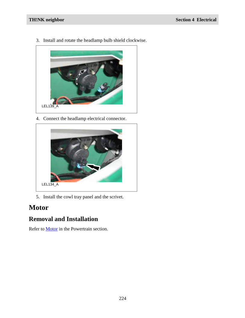
TH!NK neighbor Section 4 Electrical
224
3. Install and rotate the headlamp bulb shield clockwise.
LEL139_A
4. Connect the headlamp electrical connector.
LEL134_A
5. Install the cowl tray panel and the scrivet.
MotorRemoval and InstallationRefer to Motor in the Powertrain section.

TH!NK neighbor Section 4 Electrical
225
Motor, Wiper
LEL111_A
1
2
3
43
56
7
8
Item PartNumber
Description
1 -- Wiper Motor Shaft Washers
2 17508 Wiper Motor
3 -- Wiper Motor to Lower Bracket Nut and Bolt
4 17496 Wiper Motor Lower Bracket
5 -- Wiper Motor Upper Bracket Bolts
6 17496 Wiper Motor Upper Bracket
7 -- Wiper Motor Shaft Nut
8 17526/17528 Wiper Arm And Blade
RemovalWARNING!
MAKE SURE THE VEHICLE IS NOT BEING CHARGED.
1. Remove the front fascia. Refer to Fascia – Front in the Body Section.
2. Remove the windshield wiper arm by pressing the release lever and firmly pulling thearm straight off the shaft.
3. Remove the wiper motor shaft nut.

TH!NK neighbor Section 4 Electrical
226
4. Disconnect the wiper motor electrical connector.
5. Remove the wiper motor to lower bracket nut and bolt and remove the wiper motor.
Installation1. Reverse the removal procedure.
2. Tighten the wiper motor to lower bracket nut to 5-7N.m. (45-61lb.in.).
3. If the wiper motor was replaced adjust the wiper park as follows:
a. Turn the vehicle power on but leave the wiper switch OFF.
LEL201_A
Correct
Incorrect
b. Loosen the setscrew and rotate the disc clockwise until the wiper activates thenrotate the disc counterclockwise until the wiper stops working.
Note:
Make sure the windshield is wet prior to cycling the wipers on.
c. Tighten the setscrew and then cycle and park the wiper on wet glass a few times.
d. Repeat as necessary to ensure wiper blade park position is parallel and 4” fromthe top of the black border on the windshield.

TH!NK neighbor Section 4 Electrical
227
Heater/Defogger System ComponentsAs viewed from the front of the vehicle.
LEL206-A
Item Part Number Description1 -- Heater/defogger contactor
2 -- Rivet
3 -- Heater/defogger bracket
4 -- Heater/defogger screws
5 -- Heater/defogger duct
6 -- Nylon clamps
7 -- Tie strap
8 -- Heater/defogger bracket bolt
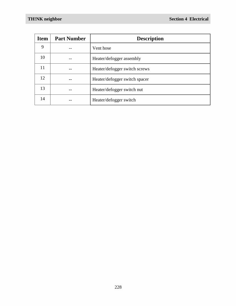
TH!NK neighbor Section 4 Electrical
228
Item Part Number Description9 -- Vent hose
10 -- Heater/defogger assembly
11 -- Heater/defogger switch screws
12 -- Heater/defogger switch spacer
13 -- Heater/defogger switch nut
14 -- Heater/defogger switch

TH!NK neighbor Section 4 Electrical
229
Heater/Defogger Assembly
LEL204-A
Item Part Number Description1 -- Heater/defogger screws
2 -- Vent hoses
3 -- Nylon clamps
4 -- Heater/defogger assembly
Removal1. Remove the front fascia. Refer to Fascia – Front in the Body section.
2. Loosen the two nylon clamps and slide the vent hoses off of the heater/defogger housing.
3. Disconnect the heater/defogger electrical connector.
4. Support the heater/defogger assembly and remove the four heater/defogger screws.
InstallationReverse the removal procedure.

TH!NK neighbor Section 4 Electrical
230
Heater/Defogger Switch
LEL205-A
Item PartNumber
Description
1 -- Heater/defogger switch spacer
2 -- Heater/defogger switch
3 -- Heater/defogger switch nuts
4 -- Heater/defogger switch screws
Removal1. Remove the scrivet and the RH cowl tray panel.
2. Disconnect the heater/defogger switch electrical connector
3. Remove the heater/defogger switch nuts.
4. Remove the heater/defogger switch screws, heater/defogger switch and spacer.
Installation1. Reverse the removal procedure.
2. Tighten the heater/defogger switch nuts to 1.75-2.25N.m (15.4-19.9lb-in.).

TH!NK neighbor Section 4 Electrical
231
Heater/Defogger Contactor
LEL207-a
Item Part Number Description1 -- Heater/defogger contactor
2 -- Heater/defogger contactor cable nuts
3 -- Rivets
4 -- Heater/defogger contactor electrical connector
Removal1. Turn the vehicle power off. Refer to the Power Shutdown Procedure in this section.
2. Remove the front fascia. Refer to Fascia – Front in the Body section.
3. Disconnect the heater/defogger contactor electrical connector.
4. Note the wire locations and remove the heater/defogger contactor cable nuts.
5. Drill out the rivets and remove the heater/defogger contactor.
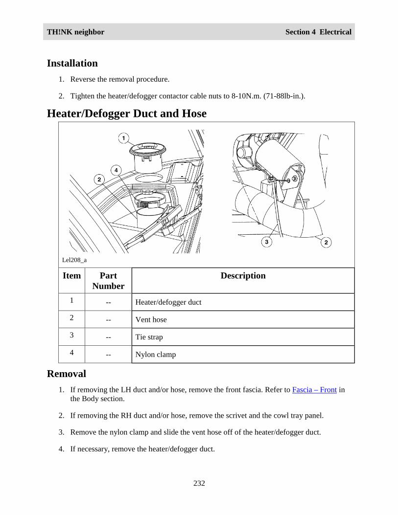
TH!NK neighbor Section 4 Electrical
232
Installation1. Reverse the removal procedure.
2. Tighten the heater/defogger contactor cable nuts to 8-10N.m. (71-88lb-in.).
Heater/Defogger Duct and Hose
Lel208_a
Item PartNumber
Description
1 -- Heater/defogger duct
2 -- Vent hose
3 -- Tie strap
4 -- Nylon clamp
Removal1. If removing the LH duct and/or hose, remove the front fascia. Refer to Fascia – Front in
the Body section.
2. If removing the RH duct and/or hose, remove the scrivet and the cowl tray panel.
3. Remove the nylon clamp and slide the vent hose off of the heater/defogger duct.
4. If necessary, remove the heater/defogger duct.

TH!NK neighbor Section 4 Electrical
233
5. Remove the nylon clamp and slide the vent hose off of the heater/defogger housing.
6. If removing the LH vent hose, cut and remove the tie strap.
7. Remove the vent hose.
InstallationReverse the removal procedure.
Power Point, 15A DC/DCRemovalWARNING!
MAKE SURE THE VEHICLE IS NOT BEING CHARGED.
1. Remove the seat stanchion cover. Refer to Seat Stanchion Cover in the Body section.
2. Turn the vehicle power off. Refer to the Power Shutdown Procedure in this section.
3. Remove the scrivet and the RH cowl tray.
4. Disconnect the power point electrical connector.
LEL125_A
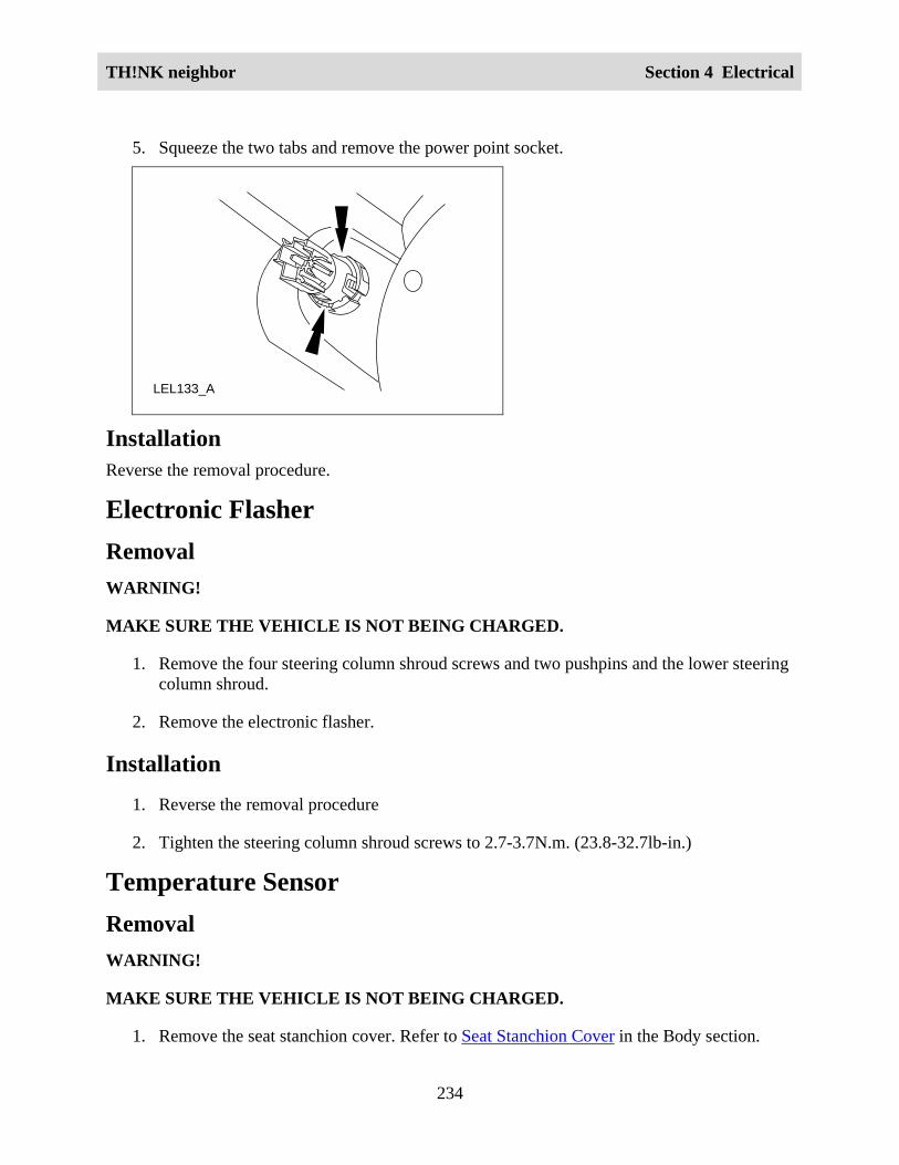
TH!NK neighbor Section 4 Electrical
234
5. Squeeze the two tabs and remove the power point socket.
LEL133_A
InstallationReverse the removal procedure.
Electronic FlasherRemovalWARNING!
MAKE SURE THE VEHICLE IS NOT BEING CHARGED.
1. Remove the four steering column shroud screws and two pushpins and the lower steeringcolumn shroud.
2. Remove the electronic flasher.
Installation1. Reverse the removal procedure
2. Tighten the steering column shroud screws to 2.7-3.7N.m. (23.8-32.7lb-in.)
Temperature SensorRemovalWARNING!
MAKE SURE THE VEHICLE IS NOT BEING CHARGED.
1. Remove the seat stanchion cover. Refer to Seat Stanchion Cover in the Body section.

TH!NK neighbor Section 4 Electrical
235
2. Turn the vehicle power off. Refer to the Power Shutdown Procedure in this section.
3. Remove the temperature sensor and disconnect the temperature sensor electricalconnector.
LEL129_A
4. Carefully remove the insulator from the switch. If damaged, replace the insulator.
InstallationReverse the removal procedure.
Switch, Drive Mode SelectorRemovalWARNING!
MAKE SURE THE VEHICLE IS NOT BEING CHARGED.
1. Remove the seat stanchion cover. Refer to Seat Stanchion Cover in the Body section.
2. Turn the vehicle power off. Refer to the Power Shutdown Procedure in this section.
3. Remove the scrivet and the LH or RH cowl tray.

TH!NK neighbor Section 4 Electrical
236
4. Disconnect the drive mode selector switch electrical connector from the back of theinstrument cluster gauge.
LEL123_A
5. Remove the spring clip retainer and the drive mode selector switch.
LEL108_A
InstallationReverse the removal procedure.
All locks should be replaced when replacing drive mode selector switch.
Switch, HornRemoval and InstallationThe horn switches are not serviced separate from the steering wheel.

TH!NK neighbor Section 4 Electrical
237
Switch, MultifunctionRemovalWARNING!
MAKE SURE THE VEHICLE IS NOT BEING CHARGED.
1. Remove the seat stanchion cover. Refer to Seat Stanchion Cover in the Body section.
3. Turn the vehicle power off. Refer to the Power Shutdown Procedure in this section.
4. Remove the four steering column shroud screws and the steering column shroud.
5. Disconnect the two multifunction switch electrical connectors.
LEL131_A
6. Remove the multifunction switch screw.
LEL132_A
Installation1. Reverse the removal procedure.

TH!NK neighbor Section 4 Electrical
238
2. Tighten the multifunction switch screw to 2.5-3.7N.m (22.1-32.7lb-in.).
3. Tighten the four steering column shroud screws to 2.7-3.7N.m (23.8-32.7lb-in.).
Switch, Service DisconnectRemoval and InstallationThe service disconnect switch can only be replaced with the newer style including the connector.If the vehicle is equipped with the hard wired service disconnect switch the harness will have tobe replaced. Refer to Wiring Harness in this section for the locations of the wiring harnesses andservice disconnect switch.
Front Turn SignalRemovalWARNING!
MAKE SURE THE VEHICLE IS NOT BEING CHARGED.
1. Remove the front fascia. Refer to Fascia – Front in the Body section.
2. Disconnect the front turn signal electrical connector.
3. Remove the front turn signal bracket bolt and the front turn signal assembly.
LEL122_A
Installation1. Reverse the removal procedure.
2. Tighten the front turn signal bracket bolt to 24-31N.m. (18-22lb-ft.)

TH!NK neighbor Section 4 Electrical
239
Rear Turn SignalRemovalWARNING!
MAKE SURE THE VEHICLE IS NOT BEING CHARGED.
1. Unlock and remove the decklid.
2. Remove the six rear bumper bolts and support the rear bumper.
3. Disconnect the rear turn signal electrical connector.
4. Remove the three rear turn signal screws and the front turn signal assembly.
LEL109_A
Front ofVehicle
Installation1. Reverse the removal procedure.
2. Tighten the three rear turn signal screws to 1.9-2.7N.m. (17-23lb-in.)
3. Tighten the six rear bumper bolts to 3.3N.m. (29lb-in.)

TH!NK neighbor Section 4 Electrical
240
Wiring Harnesses – 12VRemovalWARNING!
MAKE SURE THE VEHICLE IS NOT BEING CHARGED.
Note:
When replacing a wiring harness, contact Hotline for assistance with special steps for modifyingthe floor panels for additional clearance.
To service the wiring harnesses refer to Harness Routing in this section for locations ofharnesses.
1. Turn the vehicle power off. Refer to the Power Shutdown Procedure in this section.
2. Remove any necessary components to access the wiring harnesses, electrical connectorsand wiring harness fasteners.
3. Remove the applicable wiring harness.
InstallationReverse the removal procedure.
Wiring Harnesses – 72V (Front of vehicle)RemovalWARNING!
MAKE SURE THE VEHICLE IS NOT BEING CHARGED.
Refer to Harness Routing in this section for assistance in locating of harnesses.
1. Unlock and remove the hood.
2. Turn the vehicle power off. Refer to the Power Shutdown Procedure in this section.
3. Remove the instrument panel. Refer to Instrument Panel in this section.
4. Disconnect the accelerator potentiometer electrical connector.
5. Remove the tape from the ferrate beads and then from the beads themselves.

TH!NK neighbor Section 4 Electrical
241
6. Remove the leakage sensor lead (10 mm bolt & eyelet) from the front of the vehicle.
7. Disconnect the DC/DC converter from the high voltage wire harness.
8. Disconnect the charger electrical connector.
9. Remove the two rivets from the front passenger side of the vehicle that attach the dash tothe frame. This is where the harness is going to be pulled through, so this needs to bedone so that the connectors can be feed through.
10. Remove the front passenger side tire.
11. Remove the four rivets and the front passenger wheel well by removing the 4 rivets.
12. Pull the harness between the under body panel and the frame rail in the front passengerwheel well area
InstallationReverse the removal procedure.
Wiring Harnesses – 72V (Mid vehicle)RemovalWARNING!
MAKE SURE THE VEHICLE IS NOT BEING CHARGED.
Refer to Harness Routing in this section for assistance in locating of harnesses.
1. Turn the vehicle power off. Refer to the Power Shutdown Procedure in this section.
2. Disconnect the temperature sensor electrical connector.
LEL129_A

TH!NK neighbor Section 4 Electrical
242
3. Disconnect the contactor electrical connector.
4. Disconnect the battery negative connection from the harness to battery negative 1.
5. Remove the cluster spade from the service disconnect switch fuse box.
6. Remove the DC/DC spade from the service disconnect switch fuse box.
7. Cut the charger connection lead to the service disconnect switch fuse box.
8. Remove the service disconnect switch box.
9. Cut out floor pan where the harness will go through, cut enough out so that theconnectors can be feed through.
10. Remove the harness through the floor.
InstallationReverse the removal procedure.
Wiring Harnesses – 72V (Rear of vehicle)RemovalWARNING!
MAKE SURE THE VEHICLE IS NOT BEING CHARGED.
Refer to Harness Routing in this section for assistance in locating of harnesses.
1. Turn the vehicle power off. Refer to the Power Shutdown Procedure in this section.
2. Remove the rear passenger side tire.

TH!NK neighbor Section 4 Electrical
243
3. Disconnect the motor tachometer/speed sensor electrical connector.
LPT107_A
4. Disconnect the 23 pin motor controller electrical connector.
5. Remove the harness through the wheel well.
General ProceduresBattery ChargingWARNING!
THERE ARE GASES AROUND THE BATTERIES THAT CAN EXPLODE IFEXPOSED TO FLAMES, SPARKS, OR LIT CIGARETTES. THE AMOUNT OF GAS ISINCREASED DURING BATTERY CHARGING. AN EXPLOSION COULD RESULT INPERSONAL INJURY OR VEHICLE DAMAGE.
WARNING!
BATTERIES CONTAIN SULFURIC ACID, WHICH CAN BURN SKIN, EYES, ANDCLOTHING, IF CONTACTED.
WARNING!
DO NOT CHARGE THE BATTERIES WITH THE WEATHER ENCLOSURE CLOSEDOR THE VEHICLE COVER IN PLACE. A BUILD UP OF HYDROGEN GAS CANRESULT WHICH CAN EXPLODE. THE CHARGING AREA SHOULD BE WELLVENTILATED.
CAUTION:
If the vehicle is allowed to sit in conditions of -6°°°°C (20°°°°F) or less with a state of charge of20% (one bar showing on gauge) or less, the batteries could freeze. Allowing the batteriesto freeze may cause permanent damage to the batteries and permanently reduce their

TH!NK neighbor Section 4 Electrical
244
capacity. In cold conditions, place the vehicle in an area greater than 0°°°°C (32°°°°F) and allowit to warm up before charging. Never charge the vehicle if the batteries may be frozen.Allow the batteries to warm above 0°°°°C (32°°°°F) first, then charge.
CAUTION:
Do not park and leave the vehicle with discharged batteries. The batteries could dischargeto the point where damage could occur and the battery charger will not charge.
Note:
Make sure the service disconnect switch is on the ON position when charging.
To recharge the vehicle batteries:
Use only the GFCI cord supplied with the vehicle. If the GFCI cord does not fit the receptacle,have a qualified electrician install the proper outlet.
Note:
The outlet must be properly installed and grounded in accordance with all local codes andordinances.
1. Park the vehicle within GFCI charger cord length of a 120 volt AC 15A grounded 3-prong wall outlet.
2. Place the key in the black dot (off) position, remove the key and set the parking brake.
Note:
Make sure the power point, if equipped, is not in use and the hazard lamps are not in use.
3. Plug the GFCI charger cord into the 120volt AC 15A grounded 3-prong wall outlet. Donot use any plug adapters or extension cords to make the electrical connection.

TH!NK neighbor Section 4 Electrical
245
4. Open the charge inlet access door. Make sure that the inlet is clean and dry.
LEL127_A
5. Align the GFCI charger cord with the charge inlet and fully insert the plug into the outlet.
LEL128_A
6. Verify the POWER indicator is illuminated on the GFCI charger cord. Also, the batterycharge indicator on the instrument panel cluster will illuminate during the chargingprocess.
LEL126_A

TH!NK neighbor Section 4 Electrical
246
Note:
The humming noise you will hear is the transformer on the charger, which will operateregardless of whether the vehicle is accepting the charge.
Note:
If the charge indicator fails to display make sure the service disconnect switch is in the “ON”position.
To stop charging the vehicle batteries:
1. Push the TEST button on the GFCI charger cord. Verify the power indicator on the GFCIis off.
2. Disconnect the GFCI charger cord from the wall outlet.
3. Disconnect the GFCI charger cord from the charge inlet.
4. Close the charge inlet access door.
5. Store the cord in a safe and dry location.

TH!NK neighbor Section 4 Electrical
247
Vehicle Storage -- BatteryWARNING!
TO AVOID SERIOUS INJURY OR DEATH NEVER PERFORM ANY VEHICLESERVICE.OR MAINTENANCE WHILE THE ELECTRICAL LEAKAGE WARNING ISILLUMINATED REFER TO ELECTRICAL LEAKAGE DETECTION IN THISSECTION AND RESOLVE THE LEAKAGE CONDITION PRIOR TO BEGINNINGOTHER REPAIRS.
The service disconnect switch (see below) is located either under the driver seat cushion ortoward the center of the vehicle behind the parking brake lever within the seat stanchion. Thefront of the seat stanchion cover should be removed to access the service disconnect switch andthe fuse holders on vehicles with the switch located behind the parking brake lever. It is notencouraged to blindly reach down through the opening on top of the driver's side seat stanchioncover when the cushion is removed.
The vehicle can be stored for 14 days with the service disconnect switch on. This assumes a fullcharge when stored. If 14 days is exceeded or the batteries were not fully charged prior to storingthe vehicle the batteries may be severely discharged resulting in permanent damage. This wouldreduce the batteries capacity and vehicle range.
The vehicle can be stored with the service disconnect switch off for six months if starting with afull charge; however, the vehicle should be charged monthly if possible. With the servicedisconnect switch in the off position, there is a minimal draw from the vehicle components. Thebattery self discharge determines the storage time. This is less than 5% per month attemperatures between 4 and 21°C (40° and 70° F). The self-discharge rate increases slightly athigher temperatures. If the batteries are nearly discharged then they may freeze at 0ºC (32°F) andbelow. This will cause severe damage that may even cause battery case damage and leakage ofthe electrolyte and the inability to operate the vehicle.
When storing the neighbor:
1. Make sure the batteries are fully charged. Refer to Battery Charging in this section.

TH!NK neighbor Section 4 Electrical
248
2. If storing the vehicle for more than 14 days toggle the service disconnect switch to the OFFposition.
Switch shown in the “OFF” position
LBD161_A
Switch shown in the “ON” position
LEL203_A

TH!NK neighbor Section 4 Electrical
249
Power Shutdown ProcedureRequired ToolsHigh Voltage InsulatedGloves
100-F036 or Equivalent
Battery Post TorqueWrench
307-026 or Equivalent
Battery Terminal CapOpener
418-F215
Face Shield
100-F035 or Equivalent
Capacitor DischargeTool
418-F213+–
73 Digital Multimeter(DVOM)
105-R0051 orEquivalent
Note:
This procedure is designed to lower the voltage present on the vehicle and reduce the risk ofshock or hazard. At the end of this procedure, you will have split the battery pack into three 24Vsub-units.
Note:
Continue to use all appropriate high voltage safety procedures when working on a vehicle.
1. Remove the seat stanchion cover. Refer to Seat Stanchion Cover in the Body section.

TH!NK neighbor Section 4 Electrical
250
2. Toggle the service disconnect switch to the OFF position and wait one minute. Refer toschematic item number 5.
Switch shown in the “OFF” position
LBD161_A
Switch shown in the “ON” position
LEL203_A
3. Connect the Capacitor Discharge Tool to the DVM. Set the DVOM for DC volts.
WARNING!
THE BATTERY PACK CONTAINS HIGH-VOLTAGE COMPONENTS AND WIRING.HIGH-VOLTAGE INSULATED SAFETY GLOVES AND FACE SHIELD MUST BEWORN WHEN PERFORMING THE FOLLOWING STEPS. FAILURE TO FOLLOWTHIS WARNING MAY RESULT IN SEVERE PERSONAL INJURY OR DEATH.
WARNING!
THE BATTERY PACK ASSEMBLY CAN DELIVER IN EXCESS OF 72 VOLTS OF DCPOWER. IMPROPER HANDLING OF THE BATTERY PACK CAN RESULT ININJURY OR FATALITY. ONLY AUTHORIZED PERSONNEL TRAINED TO WORK

TH!NK neighbor Section 4 Electrical
251
WITH BATTERY PACK COMPONENTS ARE PERMITTED TO HANDLE THEBATTERIES.
WARNING!
MAKE SURE THE VEHICLE IS NOT BEING CHARGED.
1
2
LEL144_A
Item Description1 Negative Probe of DVOM to B- (battery negative, labeled “BATT 1 NEG”).
2 Positive Probe of DVOM to Load Side of 10-Amp Controller Circuit Fuse.
To discharge the motor controller:
4. Touch the negative probe of the DVOM to the B- (battery negative, which is labeled“BATT 1 NEG”).
5. Touch the positive probe of the DVOM to the load side of the 10-amp fuse for the motorcontroller circuit. This will be the spade connector closest to the front of the fuse holderand it is labeled “GAUGE/MTR-CNTR”.
6. The DVOM will display any voltage present. Repeat steps 4 and 5 if DVOM reads morethan 0 volts.
To discharge the DC/DC converter 1 (standard) or DC/DC converter 2 (optional):

TH!NK neighbor Section 4 Electrical
252
7. Touch the negative probe of the DVOM to the B- (battery negative, which is labeled“BATT 1 NEG”).
8. Touch the positive probe of the DVOM to the load side of the 10-amp fuse for theDC/DC circuit. This will be the spade connector closest to the front of the fuse holder andit is labeled “DC/DC”.
9. The DVOM will display any voltage present. Repeat steps 7 and 8 if DVOM reads morethan 0 volts.
10. Disconnect the battery cables at locations (3) and (4) and wrap the terminals on the cableswith electrical tape.

TH!NK neighbor Section 4 Electrical
253
-
+
++ - + -
- + - +
43
8
5
10
9
A1A2F2F1
F1
F2
A2A1
1
R T
D
---
2
+-11
LEL107_A
6
-
7
Item Description1 Drive Mode Selector Switch
2 Instrument Cluster Gauge
3 Battery Pack Positive Cable

TH!NK neighbor Section 4 Electrical
254
4 Battery Pack Negative Cable
5 Service Disconnect Switch
6 DC/DC Converter 1 (standard)
7 Charger
8 Motor Controller
9 Motor
10 Motor Controller 23-Pin Connector
11 Contactor
Battery Water Reminder Indicator Resetting (FloodedBatteries Only)Caution:
If the vehicle is equipped with flooded batteries, the instrument cluster gauge must beprogrammed for flooded batteries. Damage to the batteries can occur if the battery type isincorrectly programmed. Refer to Battery Type Reprogramming in this section.
Note:
The battery water reminder function of the instrument cluster gauge must be reset whenever thebattery water has been checked and filled. The indicator will illuminate every 300miles(483kms). Battery electrolyte levels should be checked every 300 miles (483kms) or monthly,whichever comes first. The only time the battery water indicator can be reset is when the key isin the R (Reverse) position, the instrument cluster gauge is in the flooded battery mode and thebattery water reminder indicator is on.
1. Turn the key to R (Reverse) position.
2. Press and hold the Select/Reset button for over 3 seconds.
3. Turn the key to the OFF (black dot) position.

TH!NK neighbor Section 4 Electrical
255
Battery Type ReprogrammingCAUTION:
If the type of battery (flooded to gel, gel to flooded) is being changed the instrument clustergauge must reprogrammed to avoid battery pack damage. The charging rate differsbetween type of battery and the battery water reminder indicator must be turned on forflooded type batteries.
1. With the key in the OFF (black dot) position, press and hold down the Select/Resetbutton.
2. Turn the key to the D (Drive) position.
3. Release the Select/Reset button.
4. Turn the key to the R (Reverse) position.
5. Press and release the Select/Reset button to alternate between the flooded and sealedbattery modes.
6. Turn the key to the OFF (black dot) position. The gauge will automatically exit thereprogramming mode after 10 seconds or exit immediately by pressing the Select/Resetbutton.
Headlamp Adjustment1. Park the vehicle on a level surface approximately 7.6m (25ft.) from a vertical wall or
screen directly in front of it.
LEL140_A
C
D
A
B
A. Eight feet.
B. Height of top of lamp beam to ground.

TH!NK neighbor Section 4 Electrical
256
C. Twenty five feet
D. Horizontal reference line.
2. Turn on the headlamps to illuminate the wall or screen.
3. The top of the headlamp beam area should be between 2’ – 2’ 3" above the ground.Adjust the headlamp adjustment nut until the beam is within this specification.
LEL138_A