section 2.0 project description - california energy commission · peaking facility consisting of...
TRANSCRIPT

SECTION 2.0
Project Description
The Chula Vista Energy Upgrade Project (CVEUP) will be a nominal 100-megawatt (MW) peaking facility consisting of two General Electric (GE) Energy LM6000 natural gas-fired turbine-generators and associated equipment. The facility will be located in Chula Vista (City), San Diego County, California, on a 3.8-acre parcel. The project site is located in the City of Chula Vista’s Main Street Industrial Corridor and within the City’s Light Industrial zoning district. The legal description of the project site is provided in Appendix 1A. Mailing address labels for all property owners within 1,000 feet of the site boundaries are provided in Appendix 1B. The project site address is 3497 Main Street, Chula Vista, California. The Assessor’s Parcel Number is 629-06-204. The site is located in Township 18S, Range 2W, Section 23 (San Bernardino Base and Meridian). Access to the site is via an access easement and lane that runs south from Main Street within an adjacent property. This lane also provides access to employee parking for newly constructed industrial buildings immediately east of the project site.
This site is currently occupied by MMC Energy Inc.’s (MMC) Chula Vista Power Plant, a 44.5-MW simple-cycle, natural gas-fired peaking power plant using Pratt & Whitney FT4 Twinpac™ technology. As part of the CVEUP, the existing power plant and pollution control equipment will be removed from the southern portion of the project parcel. The new plant, using GE Energy LM6000 technology, will be constructed on vacant land in the northern portion of the parcel. Some of the facilities that serve the existing plant will be reused for the new power plant. These facilities include the existing transmission connection; natural gas, water, and sanitary sewer pipelines; fencing and sound attenuation wall; utility/control building; stormwater runoff retention basin; and the 12,000-gallon aqueous ammonia storage tank and tank refilling station. Once the new plant is constructed, the existing plant will be dismantled and removed. The existing power equipment will be sold for salvage and the foundations, piping, and other equipment associated with the existing plant will be removed. The CVEUP will replace the existing older and less efficient technology with newer, more efficient, and cleaner technology.
Figure 2.1-1 shows the project site plan. Because the CVEUP will reuse the existing electrical transmission, natural gas, water service, and sanitary sewer pipelines, the new project will have no offsite linear appurtenances. All connections of the CVEUP to linear facilities will be made on the existing site using the existing facilities.
The existing plant connects with to San Diego Gas and Electric’s (SDG&E’s) electrical transmission system at the Otay Substation, which is approximately 1,020 feet north of the project site. This connection consists of a 69-kilovolt (kV) single-circuit transmission system mounted on wooden poles that runs north from the project parcel along its western boundary.
The existing plant connects with the Sweetwater Authority’s water supply system through a 4-inch-diameter onsite pipe. Project water uses will include turbine washes and process makeup, site landscape irrigation, and domestic and sanitary uses. The existing pipeline extends south from Main Street within an existing utility easement that runs in the access
ES062007014SAC/360346/072140005(CVEUP_002.0_PROJECT DESC.DOC) 2-1

SECTION 2.0: PROJECT DESCRIPTION
2-2 ES062007014SAC/360346/072140005(CVEUP_002.0_PROJECT DESC.DOC)
lane and connects the parcel with Main Street immediately to the east. Appendix 2A contains a “will-serve” letter from the Sweetwater Authority. Reclaimed water is not currently available in or near this location.
The CVEUP will also use the existing project’s 8-inch-diameter sanitary wastewater pipeline that currently serves the project site located within a sanitary sewer easement that runs along the western boundary of the property.
2.1 Generating Facility Description, Design, and Operation CVEUP will be a nominal 100-MW, 92 MW net (at 75 degrees Fahrenheit [°F] with duct burners), 95-MW (gross) simple-cycle generating facility configured using two GE Energy LM6000 natural gas-fired combustion turbines.
2.1.1 Site Arrangement and Layout The site plan on Figure 2.1-1 and typical elevation views on Figure 2.1-2 illustrate the design of the CVEUP. The main access to the site will be from Main Street (see Figure 1.1-3). A portion of the power block will be paved to provide internal access to all project facilities and onsite buildings. The areas around equipment, where not paved, will have gravel surfacing. The project will tie in to an existing 69-kV transmission line, which is located along the eastern boundary of the project site. Figure 2.1-3 shows panoramic photographs of the CVEUP project site, with the new project site in the foreground and the existing project in the background. The project site currently has fencing on all sides and an 18-foot-high metal sound-attenuation wall on the south, southwest, and southeastern boundaries. This fencing and the sound wall will remain as part of the new project.
2.1.2 Process Description The generating facility will consist of two LM6000 combustion turbine generators (CTGs) equipped with selective catalytic reduction (SCR) air emissions control equipment and associated support equipment. The new facility will provide a total nominal generation rating of 100 MW, gross output of 93 MW, and net capacity of 92 MW, at average annual ambient conditions of 75°F with foggers. The combustion turbines will be GE LM6000 units. The project will have black start capability using natural gas as black start engine fuel.
Each CTG will generate approximately 47 MW (gross) at base load under average ambient conditions. The project is expected to have an overall annual availability of 92 to 98 percent.
The CVEUP’s heat and mass balance diagram is shown on Figure 2.1-4. This balance is based on an ambient dry bulb temperature of 75°F (annual average), an ambient wet bulb temperature of 65°F (annual average), with duct burners and the fogging system engaged. Heat and mass balance calculations are documented in Appendix 2B.

FIGURE 2.1-1GENERAL ARRANGEMENTCHULA VISTA ENERGY UPGRADE PROJECTCITY OF CHULA VISTA, CALIFORNIA
ES062007014SAC figure_2_1_1.ai 07/27/07 tdaus
Source: WorleyParsons, 2005

North Profile
West Profile
East Profile
South Profile
FIGURE 2.1-2PLANT ELEVATIONSCHULA VISTA ENERGY UPGRADE PROJECTCITY OF CHULA VISTA, CALIFORNIA
ES062007014SAC figure_2_1_2.ai 07/06/07 tdaus

View from the Northwest
View from the Northeast
FIGURE 2.1-3SITE PHOTOGRAPHSCHULA VISTA ENERGY UPGRADE PROJECTCITY OF CHULA VISTA, CALIFORNIA
ES062007014SAC figure_2_1_3.ai 07/06/07 tdaus
Source: LSA Associates

M: Mass flow, lb/hrT: Temperature, deg FP: Pressure, psia
From Sprint WaterInjection Pumps Stack
GE LM6000PC Sprint Gas Turbine
CombustorSCR / CO Catalyst
Ambient Air
Generator
snoitceS enibruTsnoitceS rosserpmoC
Fogger Water Supply
Fuel GasNOTES1. ALL FLOW CONDITIONS ARE ESTIMATED.
From NOx Water 2. FUEL FLOW AND POWER OUTPUTInjection Pumps ARE ESTIMATED.
3. PLEASE REFER TO APPENDIX 2B FOR THE LOAD CALCULATIONS.
FIGURE 2.1-4HEAT AND MASS BALANCE DIAGRAMCHULA VISTA ENERGY UPGRADE PROJECTCITY OF CHULA VISTA, CALIFORNIA
ES062007014SAC figure_2_1_4.ai 07/27/07 tdaus
Source: WorleyParsons, 2005

SECTION 2.0: PROJECT DESCRIPTION
Associated equipment will include emission control systems necessary to meet the proposed emission limits. One-hour nitrogen oxide (NOx) emissions will be controlled at the stack to 2.0 parts per million by volume, dry basis (ppmvd), corrected to 15 percent oxygen by a combination of water injection or dry low NOx (DLN) combustors in the CTGs and SCR systems to limit 3-hour stack carbon monoxide (CO) emissions to 6.0 ppmvd. VOC emissions will also be limited to 2.0 ppmvd for VOC, during a 1-hour period.
2.1.3 Generating Facility Cycle In the CTGs, combustion air flows through the inlet air filter and associated air inlet ductwork, is compressed in the gas turbine compressor section, and then flows to the CTG combustor. Natural gas fuel is injected along with the compressed air into the combustor and then ignited. The hot combustion gases expand through the power turbine section of the CTG, causing the shaft to rotate and drive the electric generator and CTG compressor.
2.1.4 Combustion Turbine Generators Thermal energy is produced in the GE Energy LM6000 CTGs through the combustion of natural gas, which is converted into mechanical energy required to drive the combustion turbine compressors and electric generators.
Each CTG system consists of a stationary combustion turbine-generator, supporting systems, and associated auxiliary equipment. The CTGs will be equipped with the following required accessories to provide safe and reliable operation:
• Inlet air filters • Inlet air foggers • Metal acoustical enclosure • Redundant lube oil cooler • Water injection or DLN for NOx control • Compressor wash system • Fire detection and protection system
A metal acoustical housing that is located outdoors encloses the CTGs.
2.1.5 Major Electrical Equipment and Systems The bulk of the electric power produced by the facility will be transmitted to the electrical grid. A small amount of electric power will be used onsite to power auxiliaries such as pumps and fans, control systems, and general facility loads including lighting, heating, and air conditioning. A station battery system will also be used to provide direct current (DC) voltage to be used as backup power for control systems and other uses. Transmission and auxiliary uses are discussed in the following subsections.
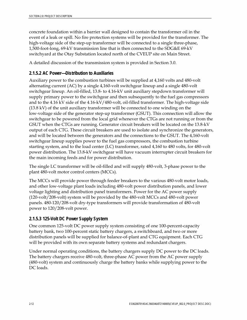
2.1.5.1 AC Power—Transmission Power will be generated by the two CTGs at 13.8 kV and then stepped up by a single three-winding transformer to 69 kV for transmission to the grid. An overall single-line diagram of the facility’s electrical system is shown on Figure 2.1-5. Surge arresters will be provided at the high-voltage bushings to protect the transformer from surges on the 69-kV system caused by lightning strikes or other system disturbances. The transformer will be set on a
ES062007014SAC/360346/072140005(CVEUP_002.0_PROJECT DESC.DOC) 2-11
SECTION 2.0: PROJECT DESCRIPTION
2-12 ES062007014SAC/360346/072140005(CVEUP_002.0_PROJECT DESC.DOC)
concrete foundation within a barrier wall designed to contain the transformer oil in the event of a leak or spill. No fire protection systems will be provided for the transformer. The high-voltage side of the step-up transformer will be connected to a single three-phase, 1,500-foot-long, 69-kV transmission line that is then connected to the SDG&E 69-kV switchyard at the Otay Substation located north of the CVEUP site on Main Street.
A detailed discussion of the transmission system is provided in Section 3.0.
2.1.5.2 AC Power—Distribution to Auxiliaries Auxiliary power to the combustion turbines will be supplied at 4,160 volts and 480-volt alternating current (AC) by a single 4,160-volt switchgear lineup and a single 480-volt switchgear lineup. An oil-filled, 13.8- to 4.16-kV unit auxiliary stepdown transformer will supply primary power to the switchgear and then subsequently to the fuel gas compressors and to the 4.16 kV side of the 4.16-kV/480-volt, oil-filled transformer. The high-voltage side (13.8 kV) of the unit auxiliary transformer will be connected to one winding on the low-voltage side of the generator step-up transformer (GSUT). This connection will allow the switchgear to be powered from the local grid whenever the CTGs are not running or from the GSUT when the CTGs are running. Generator circuit breakers will be located on the 13.8-kV output of each CTG. These circuit breakers are used to isolate and synchronize the generators, and will be located between the generators and the connections to the GSUT. The 4,160-volt switchgear lineup supplies power to the fuel gas compressors, the combustion turbine starting system, and to the load center (LC) transformer, rated 4,160 to 480 volts, for 480-volt power distribution. The 13.8-kV switchgear will have vacuum interrupter circuit breakers for the main incoming feeds and for power distribution.
The single LC transformer will be oil-filled and will supply 480-volt, 3-phase power to the plant 480-volt motor control centers (MCCs).
The MCCs will provide power through feeder breakers to the various 480-volt motor loads, and other low-voltage plant loads including 480-volt power distribution panels, and lower voltage lighting and distribution panel transformers. Power for the AC power supply (120-volt/208-volt) system will be provided by the 480-volt MCCs and 480-volt power panels. 480-120/208-volt dry-type transformers will provide transformation of 480-volt power to 120/208-volt power.
2.1.5.3 125-Volt DC Power Supply System One common 125-volt DC power supply system consisting of one 100-percent-capacity battery bank, two 100-percent static battery chargers, a switchboard, and two or more distribution panels will be supplied for balance-of-plant and CTG equipment. Each CTG will be provided with its own separate battery systems and redundant chargers.
Under normal operating conditions, the battery chargers supply DC power to the DC loads. The battery chargers receive 480-volt, three-phase AC power from the AC power supply (480-volt) system and continuously charge the battery banks while supplying power to the DC loads.
FIGURE 2.1-5FACILITY SINGLE LINE DIAGRAMCHULA VISTA ENERGY UPGRADE PROJECTCITY OF CHULA VISTA, CALIFORNIA
ES062007014SAC figure_2_1_5.ai 07/31/07 tdaus
Source: WorleyParsons, 2006

SECTION 2.0: PROJECT DESCRIPTION
Under abnormal or emergency conditions, when power from the AC power supply (480-volt) system is unavailable, the batteries supply DC power to the DC system loads. Recharging of a discharged battery occurs whenever 480-volt power becomes available from the AC power supply (480-volt) system. The rate of charge depends on the characteristics of the battery, battery charger, and the connected DC load during charging. The anticipated maximum recharge time will be 12 hours.
The 125-volt DC system will also be used to provide control power to the 4,160-volt switchgear, to the 480-volt LCs, to critical control circuits, the plant control system, and to the emergency DC motors.
2.1.5.4 Uninterruptible Power Supply System The combustion turbines and power block will also have an essential service 120-volt AC, single-phase, 60-hertz (Hz) uninterruptible power supply (UPS) to supply AC power to essential instrumentation to critical equipment loads and to unit protection and safety systems that require uninterruptible AC power.
Redundant UPS inverters will supply 120-volt AC single-phase power to the UPS panel boards that supply critical AC loads. The UPS inverters will be fed from the station 125-volt DC power supply system. Each UPS system will consist of one full-capacity inverter, a static transfer switch, a manual bypass switch, an alternate source transformer, and two or more panelboards.
The normal source of power to the system will be from the 125-volt DC power supply system through the inverter to the panelboard. A solid-state static transfer switch will continuously monitor both the inverter output and the alternate AC source. The transfer switch will automatically transfer essential AC loads without interruption from the inverter output to the alternate source upon loss of the inverter output.
A manual bypass switch will also be included to enable isolation of the inverter for testing and maintenance without interruption to the essential service AC loads.
The supervisory control system (SCS) operator stations will be supplied from the UPS. The continuous emission monitoring system (CEMS) equipment, SCS controllers, and input/output (I/O) modules will be fed using either UPS or 125-volt DC power directly.
2.1.6 Fuel System The CTGs will be designed to burn natural gas only. The natural gas requirement during base load operation at annual average ambient temperature is approximately 408.7 million British thermal units per hour (MMBtu/hr) (lower heat value [LHV] basis, total for two CTG units). The maximum natural gas requirement, experienced during low ambient temperature operation, is approximately 428.7 MMBtu/hr (LHV basis).
Natural gas is currently delivered to the site through a 8-inch-diameter pipeline (see Section 3.0). At the plant site, the natural gas will flow through a flow-metering station, gas scrubber/filtering equipment, a gas pressure control station, electric-driven booster compressors (when required), and a fuel gas heater prior to entering the combustion turbines.
ES062007014SAC/360346/072140005(CVEUP_002.0_PROJECT DESC.DOC) 2-15
SECTION 2.0: PROJECT DESCRIPTION
2-16 ES062007014SAC/360346/072140005(CVEUP_002.0_PROJECT DESC.DOC)
Historical data indicate that the pressure on the San Diego Gas and Electric (SDG&E) line generally varies between 320 and 350 psig. Three 50-percent-capacity electric-driven fuel gas compressors will be provided to boost the pressure to that required by the combustion turbines. The gas compressors will be located outdoors and will be housed in acoustical enclosures to reduce the compressor noise level.
2.1.7 Water Supply and Use This subsection describes the quantity of water required, the sources of the water supply, and water treatment requirements. Two water balance diagrams are included, representing two operating conditions. Figures 2.1-6a and 2.1-6b represent: (1) annual average operation at 75°F with two CTGs operating at 100 percent load and CTG inlet fogging, and (2) peak operation at 111°F with 2 CTGs operating at 100 percent load and CTG inlet fogging. The CVEUP will use the existing 4-inch water supply pipeline that serves the site. This pipe will also provide water for drinking, safety showers, fire protection, service water, and sanitary uses. Process water that has come into contact with the plant or its facilities is piped to a concrete-lined holding basin from which it is discharged to the sanitary sewer. Sanitary wastewater disposal will be through project site’s existing connection with the City of Chula Vista’s sanitary sewer system.
A more detailed description of the water supply system, treatment, and permits is provided in Section 5.15, Water Resources.
2.1.7.1 Water Requirements The CVEUP will use 116 gallons per minute (gpm), at the 62ºF case, of water for plant processes including fogging and turbine wash. Total water use would be about 116 gpm (average daily use), or about 28 million gallons (3.6 million cubic feet) per year, assuming operation 4,000 hours per year (45.7 percent capacity factor). A more realistic assumption would be that the plant would run a much lower percentage of the time. As shown in Table 1.1-1, simple-cycle peakers in California larger than 50 MW generally average a 6 percent capacity factor. If, for example, the CVEUP were to operate 600 hours in a year (6.8 percent capacity factor), its annual average water use would be 4.2 million gallons (12.8 acre-feet). A breakdown of the estimated average daily quantity of water, required for operation of CVEUP, is presented in Table 2.1-1.
The daily water requirements shown are estimated quantities based on the simple-cycle plant operating at full load, with fogging of the CTG inlet air. Water requirements shown in Table 2.1-1 are based on an ambient temperature of 62°F (annual average dry bulb temperature) and 111°F, respectively (1 percent exceedence dry bulb temperature based upon the American Society of Heating, Refrigerating and Air Conditioning Engineers), for average daily and maximum daily usage. Annual use is based on 116 gpm for the maximum operating scenario of 4,000 hours of operation per year and the more realistic scenario of 600 hours per year.

116.3 0
116.2 6.2
20
90
0
0.1
0.1
Notes:1. All flows are in gallons per minute.2. Foggers in operation3. 62 F DB, 54 F WB, 60% RH, Elevation 25 ft
Fire Water
Water Treatment System (Trailers)
(2) Fogging Injection System
Miscellaneous Service Water Uses
Demineralized Water Storage Tank
(2) NOx Water Injection System
(2) Sprint Water InjectionSystem
(2) LM6000PC Combustion Turbine
Oily Water Separator
Misc Process Drains
Potable Water Supply
Oil Disposal (Trucked)
Waste Disposal to Sewer
FIGURE 2.1-6ASIMPLE CYCLE WATER BALANCE - ANNUAL AVERAGECHULA VISTA ENERGY UPGRADE PROJECTCITY OF CHULA VISTA, CALIFORNIA
ES062007014SAC figure_2_1_6a.ai 07/27/07 tdaus
Source: WorleyParsons, 2006

129.1 0
129 21
28
80
0
0.1
0.1
Notes:
1. All flows are in gallons per minute.
2. Foggers in operation
3. 93 F DB, 65 F WB, 21% RH, Elevation 25 ft
Fire Water
Water Treatment System
(Trailers)(2) Fogging Injection
System
Miscellaneous Service
Water Uses
Demineralized Water
Storage Tank
(2) NOx Water Injection
System
(2) Sprint Water Injection
SystemLM6000PC Combustion
Turbine
Oily Water Separator
Misc Process Drains
Potable Water
Supply
Oil Disposal (Trucked)
Waste Disposal to
Sewer
FIGURE 2.1-6B
SIMPLE CYCLE WATER
BALANCE - MAXIMUMCHULA VISTA ENERGY UPGRADE PROJECT
CITY OF CHULA VISTA, CALIFORNIA
ES062007014SAC figure_2_1_6b.ai 08/02/07 afint
Source: WorleyParsons, 2006

SECTION 2.0: PROJECT DESCRIPTION
TABLE 2.1-1 Estimated Daily and Annual Water Use for CVEUP Operations
Water Use Average Daily Use
(gpm) Maximum Daily Use
(gpm) Average Annual Use
(afy)
Process and cooling water: 4,000 hours per year:* 600 hours per year:
116 129 85.42 afy 12.8 afy
Sanitary and domestic water 4,000 hours per year:* 600 hours per year:
0.1 0.1 24,000 gy 3,600 gy
* 4,000 hours per year represents a hypothetical capacity factor that may never occur. 600 hours per year reflects a more realistic capacity factor for a simple-cycle peaking plant. See the discussion, above.
afy = acre-feet per year gy = gallons per year
2.1.7.2 Water Quality Section 5.15 includes a projection of the water quality based on testing data from the Sweetwater Authority.
2.1.7.3 Water Treatment Service water includes all water uses at the plant except for the demineralized water used for evaporative cooling and turbine washes. Municipal water supplied by the Sweetwater Authority and protected by a reduced pressure backflow prevention device or air gap will be used for service water and for fire protection. No additional treatment of the municipal water is required for use as service water.
Service water will consist of both treated and untreated supplies. Part of the incoming water from the Sweetwater Authority will be treated by truck-mounted demineralizers and then stored in a demineralized water storage tank. Demineralized water will be required for Sprint water injection, fogger inlet cooling, water wash of the combustion turbine compressor section, and water injection for NOx control. Rental demineralizer equipment such as trailers or portable demineralizer skids will supply demineralized water to the plant. Untreated service water will be used for general (non-potable) needs such as landscaping, hose bibs (equipment and surface washdown), etc. Potable water will be used for eye-wash stations and sanitary facilities (as needed). Bottled water will be available for plant operators for drinking water. The equipment will include a number of cation and anion, or mixed bed ion exchanger vessels. The demineralizer equipment will not only include reverse osmosis units, and all demineralizer equipment will have offsite regeneration. For this reason, there will be no demineralizer waste stream. The system feedwater source is municipal water from the Sweetwater Authority.
Demineralized water will meet the following purity requirements (Table 2.1-2):
ES062007014SAC/360346/072140005(CVEUP_002.0_PROJECT DESC.DOC) 2-21

SECTION 2.0: PROJECT DESCRIPTION
TABLE 2.1-2 Demineralized Water Purity Requirements
Parameter Units Value
Total dissolved solids ppm 5
Silica as SiO2 ppm 0.1
Conductivity Micromho per centimeter <0.1 at 25°C
pH Standard unit 6.0-8.0
Sodium + potassium max ppm TBD
Chlorides max mg/L 0.5
Sulfates max mg/L 0.5
°C = degrees Celsius mg/L = milligrams per liter ppm = parts per million TBD = to be determined
The product water from the demineralizer system will be stored in a bolted, carbon steel, field-erected, factory-epoxy-coated, demineralized water tank. The tank shall be sized for 100,000 gallons, which is nominally sufficient for 12 hours of plant use.
2.1.8 Waste Management Waste management is the process whereby all wastes produced at CVEUP are properly collected, treated if necessary, and disposed of. Wastes include process and sanitary wastewater, nonhazardous waste and hazardous waste, both liquid and solid. Waste management is discussed in more detail in Section 5.14.
2.1.8.1 Wastewater Collection, Treatment, and Disposal The primary wastewater collection system will collect process wastewater and stormwater runoff from all of the plant equipment and route it to the existing retention basin for testing before discharge to the sanitary wastewater system. The secondary wastewater collection system will collect sanitary wastewater from sinks, toilets, showers, and other sanitary facilities, and discharge it via the City of Chula Vista’s sanitary sewer system. The water balance diagrams, Figures 2.1-6a and 2.1-6b, show the expected wastewater streams and flow rates for CVEUP for the annual average and maximum conditions, respectively.
2.1.8.1.1 Plant Drains and Oil/Water Separator General plant drains will collect containment area washdown, sample drains, and drainage from facility equipment drains. Water from these areas will be collected in a system of floor drains, hub drains, sumps, and piping and routed to the wastewater collection system. Drains that potentially could contain oil or grease will first be routed through an oil/water separator. Water from the plant wastewater collection system will be discharged to the sanitary sewer. Wastewater from combustion turbine water washes will be collected in holding tanks or sumps and will be trucked offsite for disposal at an approved wastewater disposal facility.
2-22 ES062007014SAC/360346/072140005(CVEUP_002.0_PROJECT DESC.DOC)

SECTION 2.0: PROJECT DESCRIPTION
2.1.8.1.2 Process Water Treatment Wastes The process water treatment system will consist of onsite of multimedia filters and demineralizers. The system will be housed in a trailer-mounted unit. The unit will be regenerated offsite.
2.1.8.2 Solid Wastes CVEUP will produce maintenance and plant wastes typical of power generation operations. Generation plant wastes include oily rags, broken and rusted metal and machine parts, defective or broken electrical materials, empty containers, and other solid wastes, including the typical refuse generated by workers. Solid wastes will be trucked offsite for recycling or disposal (see Section 5.14).
2.1.8.3 Hazardous Wastes Several methods will be used to properly manage and dispose of hazardous wastes generated by CVEUP. Waste lubricating oil will be recovered and recycled by a waste oil recycling contractor. Spent lubrication oil filters will be disposed of in a Class I landfill. Spent SCR and oxidation catalysts will be recycled by the supplier or disposed of in accordance with regulatory requirements. Workers will be trained to handle hazardous wastes generated at the site.
Chemical cleaning wastes will consist of alkaline and acid cleaning solutions used during pre-operational chemical cleaning and turbine washwaters. These wastes, which are subject to high metal concentrations, will be temporarily stored onsite in portable tanks or sumps, and disposed of offsite by the chemical cleaning contractor in accordance with applicable regulatory requirements.
2.1.9 Management of Hazardous Materials There will be a variety of chemicals stored and used during construction and operation of CVEUP. The storage, handling, and use of all chemicals will be conducted in accordance with applicable laws, ordinances, regulations, and standards (LORS). Chemicals will be stored in appropriate chemical storage facilities. Bulk chemicals will be stored in storage tanks, and most other chemicals will be stored in returnable delivery containers. Chemical storage and chemical feed areas will be designed to contain leaks and spills. Concrete containment pits and drain piping design will allow a full-tank capacity spill without overflowing the containment area. For multiple tanks located within the same containment area, the capacity of the largest single tank will determine the volume of the containment area and drain piping. Drain piping for reactive chemicals will be trapped and isolated from other drains to eliminate noxious or toxic vapors.
The aqueous ammonia storage and delivery area will have spill containment and ammonia vapor detection equipment.
Safety showers and eyewashes will be provided adjacent to, or in the vicinity of, chemical storage and use areas. Plant personnel will use approved personal protective equipment during chemical spill containment and cleanup activities. Personnel will be properly trained in the handling of these chemicals and instructed in the procedures to follow in case of a
ES062007014SAC/360346/072140005(CVEUP_002.0_PROJECT DESC.DOC) 2-23

SECTION 2.0: PROJECT DESCRIPTION
chemical spill or accidental release. Adequate supplies of absorbent material will be stored onsite for spill cleanup.
A list of the chemicals anticipated to be used at CVEUP and their storage locations is provided in Section 5.5, Hazardous Materials Handling. This list identifies each chemical by type, intended use, and estimated quantity to be stored onsite.
2.1.10 Emission Control and Monitoring Air emissions from the combustion of natural gas in the CTGs will be controlled using state-of-the-art systems. To ensure that the systems perform correctly, continuous emissions monitoring for NOx and CO will be performed. Section 5.1, Air Quality, includes additional information on emission control and monitoring.
2.1.10.1 NOx Emission Control The CTGs selected for the project include state-of-the-art DLN combustors designed to control emissions of NOX. The SCR process will use 19-percent aqueous ammonia. Ammonia slip, or the concentration of unreacted ammonia in the stack exhaust, will be limited to 5 ppmv, averaged over 1 hour. The SCR equipment will include a reactor chamber, catalyst modules, ammonia storage system, ammonia vaporization and injection system, and monitoring equipment and sensors. The project will make use of the existing ammonia delivery system, which consists of a 12,000-gallon ammonia tank, spill containment basin, and refilling station with a spill containment basin and sump.
2.1.10.2 Carbon Monoxide and Volatile Organic Compound Emission Control The combustion turbine combustors incorporate staged combustion of a pre-mixed fuel/air charge, resulting in high thermal efficiencies with reduced CO and VOC emissions. CO and VOC emissions will be further controlled by means of a CO oxidation catalyst. CO and VOC emission rates in stack exhaust will be limited to 6 ppmv, averaged over 3 hours and 1 hour, respectively.
2.1.10.3 Particulate Emission Control Particulate emissions will be controlled by the use of best combustion practices; the use of natural gas, which is low in sulfur, as the sole fuel for the CTGs; and high efficiency air inlet filtration.
2.1.10.4 Continuous Emission Monitoring For each CTG, a separate CEMS will sample, analyze, and record fuel gas flow rate, NOx and CO concentration levels, and percentage of oxygen in the exhaust gas from the stacks. The CEMS sensors will transmit data to a data acquisition system (DAS) that will store the data and generate emission reports in accordance with permit requirements. The DAS will also include alarm features that will send signals to the plant SCS when the emissions approach or exceed pre-selected limits.
2-24 ES062007014SAC/360346/072140005(CVEUP_002.0_PROJECT DESC.DOC)

SECTION 2.0: PROJECT DESCRIPTION
2.1.11 Fire Protection The fire protection system will be designed to protect personnel and limit property loss and plant downtime in the event of a fire. The primary source of fire protection water will be the Sweetwater Authority’s potable water system.
Fixed fire suppression systems will be installed at determined fire risk areas such as the transformers and turbine lube oil equipment. Sprinkler systems will also be installed in the Administration/Control/Warehouse/Maintenance Building and Fire Pump enclosure as required by the National Fire Protection Agency (NFPA) and local code requirements. The CTG units will be protected by a carbon dioxide fire protection system. Handheld fire extinguishers of the appropriate size and rating will be located in accordance with NFPA 10 throughout the facility.
Section 5.5, Hazardous Materials Handling, includes additional information for fire and explosion risk, and Section 5.10, Socioeconomics, provides information on local fire protection capability.
2.1.12 Plant Auxiliaries The following systems will support, protect, and control the generating facility.
2.1.12.1 Lighting The lighting system provides personnel with illumination for operation under normal conditions and for egress under emergency conditions, and includes emergency lighting to perform manual operations during an outage of the normal power source. The system also provides 120-volt convenience outlets for portable lamps and tools.
2.1.12.2 Grounding The electrical system is susceptible to ground faults, lightning, and switching surges that result in high voltage that constitute a hazard to site personnel and electrical equipment. The station grounding system provides an adequate path to permit the dissipation of current created by these events.
The station grounding grid will be designed for adequate capacity to dissipate the ground fault current from the ground grid under the most severe conditions in areas of high ground fault current concentration. The grid spacing will maintain safe voltage gradients.
Bare conductors will be installed below-grade in a grid pattern. Each junction of the grid will be bonded together by an exothermic weld.
Ground resistivity readings will be used to determine the necessary numbers of ground rods and grid spacing to ensure safe step and touch potentials under severe fault conditions.
Grounding conductors will be brought from the ground grid to connect to building steel and non-energized metallic parts of electrical equipment.
2.1.12.3 Supervisory Control System The SCS provides modulating control, digital control, monitoring, and indicating functions for the plant power block systems.
ES062007014SAC/360346/072140005(CVEUP_002.0_PROJECT DESC.DOC) 2-25

SECTION 2.0: PROJECT DESCRIPTION
The SCS will provide the following functions:
• Controlling the CTGs and other systems in a coordinated manner
• Controlling the balance-of-plant systems in response to plant demands
• Monitoring controlled plant equipment and process parameters and delivery of this information to plant operators
• Providing control displays (printed logs, LCD video monitors) for signals generated within the system or received from I/O
• Providing consolidated plant process status information through displays presented in a timely and meaningful manner
• Providing alarms for out-of-limit parameters or parameter trends, displaying on alarm video monitors(s), and recording on an alarm log printer
• Providing storage and retrieval of historical data
The SCS will be a redundant microprocessor-based system and will consist of the following major components:
• PC-based operator consoles with LCD video monitors • I/O cabinets • Historical data unit • Printers • Data links to the combustion turbine and steam turbine control systems
The SCS will have a functionally distributed architecture allowing integration of balance-of-plant equipment that may be controlled locally via a programmable logic controller.
The SCS will interface with the control systems furnished by the CTG suppliers to provide remote control capabilities, as well as data acquisition, annunciation, and historical storage of turbine and generator operating information.
The system will be designed with sufficient redundancy to preclude a single device failure from significantly affecting overall plant control and operation. This also will allow critical control and safety systems to have redundancy of controls, as well as an uninterruptible power source.
As part of the quality control program, daily operator logs will be available for review to determine the status of the operating equipment.
2.1.12.4 Cathodic Protection The cathodic protection system will be designed to control the electrochemical corrosion of designated metal piping buried in the soil. Depending upon the corrosion potential and the site soils, either passive or impressed current cathodic protection will be provided.
2-26 ES062007014SAC/360346/072140005(CVEUP_002.0_PROJECT DESC.DOC)

SECTION 2.0: PROJECT DESCRIPTION
2.1.12.5 Service Air The service air system will supply compressed air to hose connections for general plant use. Service air headers will be routed to hose connections located at various points throughout the facility.
2.1.12.6 Instrument Air The instrument air system will provide dry air to pneumatic operators and devices. An instrument air header will be routed to locations within the facility equipment areas and within the water treatment facility where pneumatic operators and devices will be located.
2.1.13 Interconnect to Electrical Grid The two CTGs will connect to the regional electrical grid using the transmission connection and takeoff structure that is located on the existing site. This structure connects with a single-circuit 69-kV transmission line on one set of wooden support poles that exits the site along the eastern boundary of the property and connects to the SDG&E Otay Substation (see Section 3.0, Electric Transmission).
2.1.14 Project Construction Construction of the generating facility, from site preparation and grading to commercial operation, is expected to take place from the third quarter of 2008 to the second quarter of 2009 (8 months total). Major milestones are listed in Table 2.1-3.
TABLE 2.1-3 CVEUP Project Schedule Major Milestones
Activity Date
Begin Construction Third Quarter 2008
Startup and Test Second Quarter 2009
Commercial Operation Third Quarter 2009
There will be an average and peak workforce of approximately 100 and 160, respectively, of construction craft people, supervisory, support, and construction management personnel onsite during construction (see Table 5.10-11).
Typically, noisy construction will be scheduled to occur between 6 a.m. and 7 p.m. on weekdays and Saturdays. Additional hours may be necessary to make up schedule deficiencies, or to complete critical construction activities (e.g., pouring concrete at night during hot weather, working around time-critical shutdowns and constraints). During some construction periods and during the startup phase of the project, some activities will continue 24 hours per day, 7 days per week.
The peak construction site workforce level is expected to last from Month 3 through Month 5 of the construction period, with the peak being Month 4.
ES062007014SAC/360346/072140005(CVEUP_002.0_PROJECT DESC.DOC) 2-27

SECTION 2.0: PROJECT DESCRIPTION
2-28 ES062007014SAC/360346/072140005(CVEUP_002.0_PROJECT DESC.DOC)
Table 2.1-4 provides an estimate of the average and peak construction traffic during the 8-month construction period for the plant.
TABLE 2.1-4 Estimated Average and Peak Construction Traffic for the CVEUP
Vehicle Type Average Daily Trips Peak Daily Trips
Construction Workers 79 160
Deliveries 15 15
Total 94 175
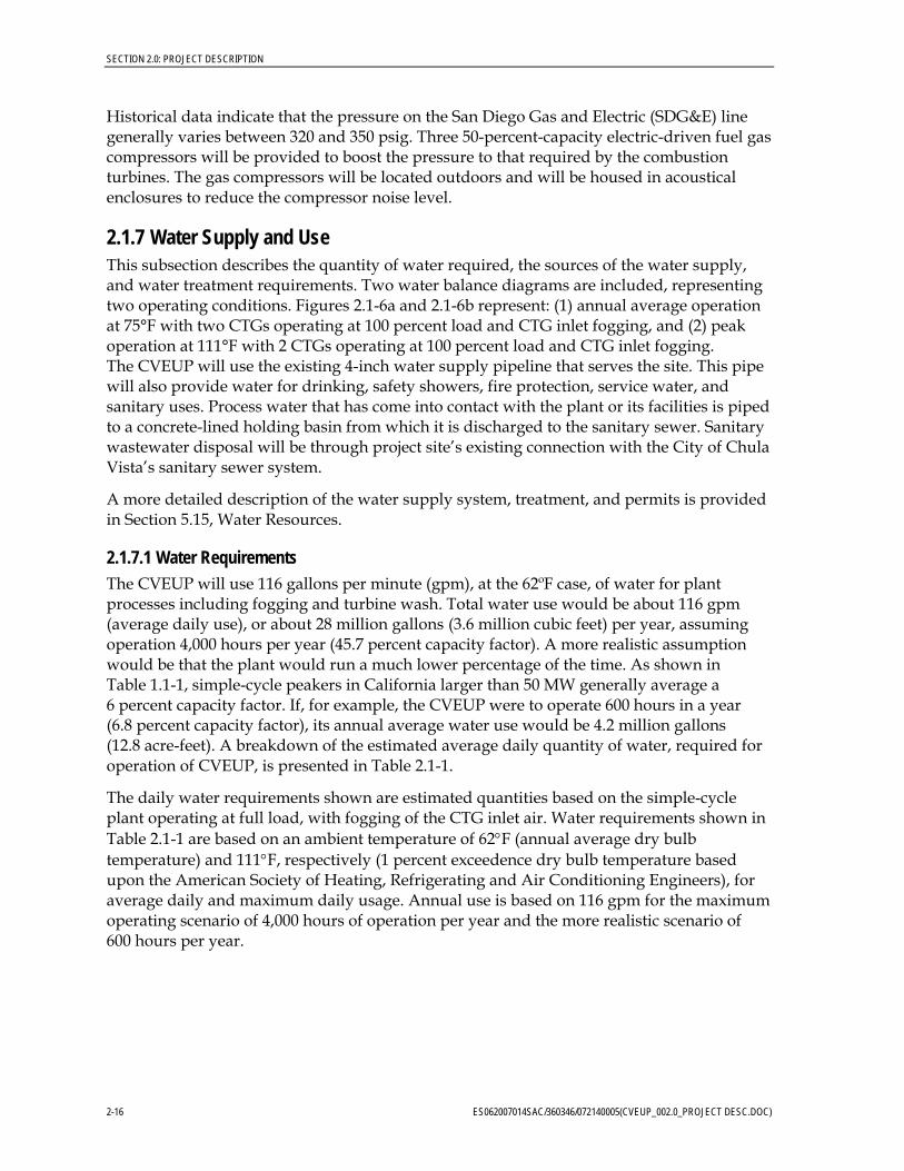
There are two alternative construction laydown and worker parking areas for the project: (1) a currently vacant, 5.0-acre former pallet storage yard immediately south and west of the project site; and (2) a 2.75-acre parcel currently used for construction laydown at 2000 Heritage Road in Chula Vista (APN 644-050-11-00), 3.4 miles east of the CVEUP site. Figure 2.1-7 shows the project site in relation to the two alternative construction laydown and parking yards. Materials and equipment will be delivered by truck. If Alternative 2 were chosen, workers would be bussed from the worker parking area to the project. There would be 24 worker bus trips to the project per day (four daily trips for each of six buses, two in the morning and two in the afternoon).
2.1.15 Generating Facility Operation CVEUP will have a single operator during the standard 5-day, 8-hour per day work week.
CVEUP is expected to have an annual plant availability of 92 to 98 percent. It will be possible for plant availability to exceed 98 percent for a given 12-month period. MMC expects to operate the CVEUP primarily as a peaker unit, with some amount of load following and cycling. The exact operational profile of the plant, however, cannot be defined in detail since operation of the facility depends on the variable demand in the CVEUP service area.
The facility may be operated in one or all of the following modes:
• Load Following. During non-peak seasons (primarily spring and fall), the facility would be operated at loads that may vary between maximum continuous output (both of the CTGs operating at base load) and minimum load (one CTG operating as low as 60-percent load) to meet electrical demand at all times of the day.
• Daily Cycling. During low demand periods, the facility may be operated in daily cycling mode, where the plant is operated at loads up to maximum continuous output during the day and totally shut down at night or weekends. This mode of operation may occur either with daily nighttime shutdowns or with weekend shutdowns depending on electrical demand, hydroelectric power availability, and other issues.
• Full Shutdown. This would occur if forced by equipment malfunction, fuel supply interruption, transmission line disconnect, or scheduled maintenance.
%&s(
Main Street
Palm Ave
Picador Blvd
Alba
ny A
ve
City of Chula Vista
City of San Diego
Otay Substation
SAC\\GLACIER\PROJ\360346_MMC\MAPFILES\LAYDOWNLOCATIONS.MXD 6/29/2007
LEGENDAccess RouteCVEEUP Project SiteProposed Laydown AreaCity Boundaries
0 2,0001,000Feet
1:24,000
FIGURE 2.1-7CONSTRUCTION LAYDOWN AND PARKING AREASCHULA VISTA ENERGY EFFICIENCY UPGRADE PROJECTCHULA VISTA, CALIFORINA

SECTION 2.0: PROJECT DESCRIPTION
In the unlikely event of a situation that causes a longer-term cessation of operations, security of the facilities will be maintained on a 24-hour basis, and the California Energy Commission (CEC) will be notified. Depending on the length of shutdown, a contingency plan for the temporary cessation of operations may be implemented. Such contingency plan will be in conformance with all applicable LORS and protection of public health, safety, and the environment. The plan, depending on the expected duration of the shutdown, could include the draining of all chemicals from storage tanks and other equipment and the safe shutdown of all equipment. All wastes will be disposed of according to applicable LORS. If the cessation of operations becomes permanent, the plant will be decommissioned (see Section 2.3, Facility Closure).
2.2 Engineering In accordance with CEC regulations, this section, together with the engineering appendices and Section 4.0 (Gas Supply), presents information concerning the design and engineering of CVEUP. The LORS applicable to the engineering of the CVEUP are provided along with a list of agencies that have jurisdiction, the contact persons within those agencies, and a list of the permits that will be required.
2.2.1 Facility Design Summary descriptions of the design criteria for all of the major engineering disciplines are included in Appendix 2C, Design Criteria:
Appendix 2D contains an Initial Geotechnical Report for the CVEUP site based on borings taken at the project site.
Design and engineering information and data for the following systems are found in the following subsections of this Application for Certification:
• Power Generation—See Section 2.1.4, Combustion Turbine Generators. Also see Appendix 2C and Sections 2.1.5 through 2.1.13, which describe the various plant auxiliaries.
• Heat Dissipation—See Appendix 2C.
• Cooling Water Supply System—See Section 2.1.7, Water Supply and Use; and Appendix 2C.
• Air Emission Control System—See Section 2.1.10, Emission Control and Monitoring, and Section 5.1, Air Quality.
• Waste Disposal System—See Section 2.1.8 and Section 5.14, Waste Management.
• Noise Abatement System—See Section 5.7, Noise.
• Switchyards/Transformer Systems—See Section 2.1.5, Major Electrical Equipment and Systems; Section 2.1.12.2, Grounding; Section 2.1.5.1, AC Power—Transmission; Section 2.1.13, Interconnect to Electrical Grid; Section 3.0, Electric Transmission; and Appendix 2C.
ES062007014SAC/360346/072140005(CVEUP_002.0_PROJECT DESC.DOC) 2-31

SECTION 2.0: PROJECT DESCRIPTION
2.2.1.1 Facility Safety Design CVEUP will be designed to maximize safe operation. Potential hazards that could affect the facility include earthquake, flood, and fire. Facility operators will be trained in safe operation, maintenance, and emergency response procedures to minimize the risk of personal injury and damage to the plant.
2.2.1.1.1 Natural Hazards The principal natural hazard associated with the CVEUP site is earthquakes. The site is located in Seismic Risk Zone 4. Structures will be designed to meet the seismic requirements of CCR Title 24 and the 2001 California Building Code (CBC). Section 5.4, Geologic Hazards and Resources, includes a review of potential geologic hazards, seismic ground motion, and potential for soil liquefaction due to ground-shaking.. Potential seismic hazards will be mitigated by implementing the 2001 CBC construction guidelines. Appendix 2B, Structural Engineering, includes the structural seismic design criteria for the buildings and equipment.
Flooding is not a hazard of concern. According to the Federal Emergency Management Agency (FEMA), the site is not within either the 100- or 500-year flood plain. Section 5.15, Water Resources, includes additional information on the potential for flooding.
2.2.1.1.2 Emergency Systems and Safety Precautions This section discusses the fire protection systems, emergency medical services, and safety precautions to be used by project personnel. Section 5.10, Socioeconomics, includes additional information on area medical services, and Section 5.16, Worker Safety, includes additional information on safety for workers. Appendix 2C contain the design practices and codes applicable to safety design for the project. Compliance with these requirements will minimize project effects on public and employee safety.
Fire Protection Systems The project will rely on both onsite fire protection systems and local fire protection services.
Onsite Fire Protection Systems The fire protection systems are designed to protect personnel and limit property loss and plant downtime from fire or explosion. The project will have the following fire protection systems.
Carbon Dioxide and Dry Chemical Fire Protection Systems—These systems protect the combustion turbines and certain accessory equipment compartments from fire. The system will have fire detection sensors in all protected compartments. Actuating one sensor will provide a high-temperature alarm on the combustion turbine control panel. Actuating a second sensor will trip the combustion turbine, turn off ventilation, close ventilation openings, and automatically release the gas and chemical agents. The gas and chemical agents will be discharged at a design concentration adequate to extinguish the fire.
Fire Hydrants/Hose Stations—This system will supplement the plant’s fixed fire suppression systems. Water will be supplied from the plant fire water system.
Fire Extinguisher—The plant administrative/control/warehouse/maintenance building, water treatment building, and other structures will be equipped with fixed fire suppression systems and portable fire extinguishers as required by the local fire department.
2-32 ES062007014SAC/360346/072140005(CVEUP_002.0_PROJECT DESC.DOC)

SECTION 2.0: PROJECT DESCRIPTION
Local Fire Protection Services In the event of a major fire, the plant personnel will be able to call upon the Chula Vista Fire Department for assistance. The Hazardous Materials Business Plan (see Section 5.5, Hazardous Materials Handling) for the plant will include all information necessary to allow fire-fighting and other emergency response agencies to plan and implement safe responses to fires, spills, and other emergencies.
Personnel Safety Program The CVEUP project will operate in compliance with federal and state occupational safety and health program requirements. Compliance with these programs will minimize project effects on employee safety. These programs are described in Section 5.16, Worker Safety.
2.2.2 Facility Reliability This section discusses the expected facility availability, equipment redundancy, fuel availability, water availability, and project quality control measures.
2.2.2.1 Facility Availability The facility will be designed to operate between about 40 and 100 percent of base load to support dispatch service in response to customer demands for electricity.
CVEUP will be designed for an operating life of 30 years. Reliability and availability projections are based on this operating life. Operation and maintenance procedures will be consistent with industry standard practices to maintain the useful life status of plant components.
The percent of time that the simple-cycle power plant is projected to be operated is defined as the “service factor.” The service factor considers the amount of time that a unit is operating and generating power, whether at full or partial load. The projected service factor for the simple-cycle power block, which considers projected percent of time of operation, differs from the equivalent availability factor (EAF), which considers the projected percent of energy production capacity achievable.
The EAF may be defined as a weighted average of the percent of full energy production capacity achievable. The projected equivalent availability factor for the CVEUP is estimated to be approximately 92 to 98 percent.
The EAF, which is a weighted average of the percent of energy production capacity achievable, differs from the “availability of a unit,” which is the percent of time that a unit is available for operation, whether at full load, partial load, or standby.
2.2.2.2 Redundancy of Critical Components The following subsections identify equipment redundancy as it applies to project availability. A summary of equipment redundancy is shown in Table 2.2-1. Final design could differ.
ES062007014SAC/360346/072140005(CVEUP_002.0_PROJECT DESC.DOC) 2-33

SECTION 2.0: PROJECT DESCRIPTION
TABLE 2.2-1 Major Equipment Redundancy at CVEUP
Description Number
Simple-cycle CTGs Two
Fuel gas booster compressors Three—50-percent capacity
Demineralizer system Two—100-percent capacity
2.2.2.2.1 Plant Power Generation Process Description Two separate CTG power generation trains will operate in parallel in a simple-cycle mode. Each CTG will provide approximately 50 percent of the total plant power output.
The major components of the plant process consist of the following subsystems.
Combustion Turbine Generator Subsystems The combustion turbine subsystems include the combustion turbine, inlet air filtration and foggers, generator and excitation systems, turbine lube oil system, hydraulic system, and turbine control and instrumentation. The combustion turbine will produce thermal energy through the combustion of natural gas and the conversion of the thermal energy into mechanical energy through rotation of the combustion turbine that drives the compressor and generator.
The generator excitation system will be a solid-state static system. Combustion turbine control and instrumentation (interfaced with the SCS) will cover the turbine governing system, and the protective system.
The plant power generation process is served by the following balance-of-plant systems.
Supervisory Control System The SCS will be a microprocessor-based system that will provide the following functions:
• Control each CTG via their dedicated Turbine Control System and other systems in response to unit load demands (coordinated control)
• Provide control room operator interface
• Monitor plant equipment and process parameters and provide this information to the plant operators in a meaningful format
• Provide visual and audible alarms for abnormal events based on field signals or software-generated signals from plant systems, processes, or equipment
The SCS will have functionally distributed architecture comprising a group of similar redundant processing units linked to a group of operator consoles and an engineer workstation by redundant data highways. Each processor will be programmed to perform specific dedicated tasks for control information, data acquisition, annunciation, and historical purposes.
2-34 ES062007014SAC/360346/072140005(CVEUP_002.0_PROJECT DESC.DOC)

SECTION 2.0: PROJECT DESCRIPTION
Plant operation will be controlled from the operator panel located in the control room. The operator panel will consist of two individual video/keyboard consoles. Each video/keyboard console will be an independent electronic package so that failure of a single package does not disable more than one video/keyboard.
Demineralized Water System The demineralized water system will consist of two 100-percent truck-mounted water demineralizers from an onsite water treatment system consisting of multimedia filters, ultrafiltration, a reverse osmosis unit, and an e-cell exchanger. Demineralized water will be stored in a 100,000-gallon demineralized water storage tank.
Power Cycle Makeup and Storage The power cycle makeup and storage subsystem provides demineralized water storage and pumping capabilities to supply high-purity water for system cycle makeup and chemical cleaning operations. Major components of the system are the demineralized water storage tank, providing for more than a 24-hour supply of demineralized water at peak load, and two 100-percent capacity, horizontal, centrifugal, cycle makeup water pumps.
Compressed Air The compressed air system provides instrument air and service air to points of use throughout the facility. The compressed air system will include two 100-percent-capacity, motor-driven air compressors; two 100-percent capacity air dryers with prefilters and after filters; an air receiver, instrument air header, and service air header. All compressed air will be dried. A control valve will be provided in the service air header to prevent high consumption of service air from reducing the instrument air header pressure below critical levels.
2.2.2.3 Fuel Availability Fuel will be delivered via the existing pipeline that serves the project site. This pipeline connects with SDG&E’s distribution line located along Main Street. It is possible that the connecting line to CVEUP could become temporarily inoperable due to a breach in the line or from other causes, resulting in fuel not being available at the CVEUP.
2.2.2.4 Water Availability The CVEUP project will use up to 28 million gallons per year of water for turbine inlet air fogging, turbine water injection, compressor water washes and other process uses. Potable water for drinking, safety showers, fire protection water, service water, and sanitary uses will be served from the Sweetwater Authority’s water system distribution system. Recycled water is not available from Sweetwater Authority or other sources in this location.
The availability of water to meet the needs of CVEUP is discussed in more detail in Section 5.15, Water Resources. A will-serve letter from the Sweetwater Authority is included in Appendix 2A.
2.2.2.5 Project Quality Control The Quality Control Program that will be applied to CVEUP is summarized in this subsection. The objective of the Quality Control Program is to ensure that all systems and components have the appropriate quality measures applied; whether during design, procurement, fabrication, construction, or operation. The goal of the Quality Control
ES062007014SAC/360346/072140005(CVEUP_002.0_PROJECT DESC.DOC) 2-35

SECTION 2.0: PROJECT DESCRIPTION
Program is to achieve the desired levels of safety, reliability, availability, operability, constructability, and maintainability for the generation of electricity.
The required quality assurance for a system is obtained by applying controls to various activities, according to the activity being performed. For example, the appropriate controls for design work are checking and review, and the appropriate controls for manufacturing and construction are inspection and testing. Appropriate controls will be applied to each of the various activities for the project.
2.2.2.5.1 Project Stages For quality assurance planning purposes, the project activities have been divided into the following ten stages that apply to specific periods during the project:
• Conceptual Design Criteria. Activities such as definition of requirements and engineering analyses.
• Detail Design. Activities such as the preparation of calculations, drawings, and lists needed to describe, illustrate, or define systems, structures, or components.
• Procurement Specification Preparation. Activities necessary to compile and document the contractual, technical, and quality provisions for procurement specifications for plant systems, components, or services.
• Manufacturer’s Control and Surveillance. Activities necessary to ensure that the manufacturers conform to the provisions of the procurement specifications.
• Manufacturer Data Review. Activities required to review manufacturers’ drawings, data, instructions, procedures, plans, and other documents to ensure coordination of plant systems and components, and conformance to procurement specifications.
• Receipt Inspection. Inspection and review of product at the time of delivery to the construction site.
• Construction/Installation. Inspection and review of storage, installation, cleaning, and initial testing of systems or components at the facility.
• System/Component Testing. Actual operation of generating facility components in a system in a controlled manner to ensure that the performance of systems and components conform to specified requirements.
• Decommissioning, Dismantling, and Removal of the Existing Plant. Once the new plant is nearing the full system testing phase, the gas metering equipment, ammonia supply tank, and stormwater retention pond will be disconnected from the existing plant and connected with the new equipment. The existing plant will then be decommissioned, dismantled, and removed.
• Plant Operation. As the project progresses, the design, procurement, fabrication, erection, and checkout of each generating facility system will progress through the nine stages defined above.
2-36 ES062007014SAC/360346/072140005(CVEUP_002.0_PROJECT DESC.DOC)

SECTION 2.0: PROJECT DESCRIPTION
2.2.2.5.2 Quality Control Records The following quality control records will be maintained for review and reference:
• Project instructions manual • Design calculations • Project design manual • Quality assurance audit reports • Conformance to construction records drawings • Procurement specifications (contract issue and change orders) • Purchase orders and change orders • Project correspondence
For procured component purchase orders, a list of qualified suppliers and subcontractors will be developed. Before contracts are awarded, the subcontractors’ capabilities will be evaluated. The evaluation will consider suppliers’ and subcontractors’ personnel, production capability, past performance, and quality assurance program.
During construction, field activities are accomplished during the last four stages of the project: receipt inspection, construction/installation, system/component testing, and plant operations. The construction contractor will be contractually responsible for performing the work in accordance with the quality requirements specified by contract.
The subcontractors’ quality compliance will be surveyed through inspections, audits, and administration of independent testing contracts.
A plant operation and maintenance program, typical of a project this size, will be implemented by the CVEUP to control operation and maintenance quality. A specific program for this project will be defined and implemented during initial plant startup.
2.2.3 Thermal Efficiency The maximum thermal efficiency that can be expected from a natural gas-fired simple-cycle plant using GE LM6000 combustion turbine units is approximately 40 percent on a higher heating value (HHV) basis. This level of efficiency is achieved when a facility is base-loaded. The CVEUP is estimated to have a thermal efficiency of 55 to 56 percent LHV at base load and annual average ambient conditions. Other types of operations, particularly those at less than full gas turbine output, will result in lower efficiencies. The basis of the CVEUP operations will be system dispatch within California’s power generation and transmission system. It is expected that CVEUP will be primarily operated in load following or cycling service. The number of startup and shutdown cycles is expected to range between zero and 365 per year per CTG.
Plant fuel consumption will depend on the operating profile of the power plant. It is estimated that the range of fuel consumed by the power plant will be from a minimum of near zero British thermal units (Btu) per hour to a maximum of approximately 469.7 million Btu per hour (HHV basis) at base load and minimum ambient conditions.
The net annual electrical production of the CVEUP cannot be accurately forecasted at the present time due to uncertainties in the system load dispatching model and the associated policies. However, due to the efficiency of the plant, its operating characteristics will be as
ES062007014SAC/360346/072140005(CVEUP_002.0_PROJECT DESC.DOC) 2-37

SECTION 2.0: PROJECT DESCRIPTION
described above. The maximum annual generation possible from the facility is estimated to be approximately 372 gigawatt hours per year.
2.3 Facility Closure Facility closure can be temporary or permanent. Temporary closure is defined as a shutdown for a period exceeding the time required for normal maintenance, including closure for overhaul or replacement of the combustion turbines. Causes for temporary closure include a disruption in the supply of natural gas or damage to the plant from earthquake, fire, storm, or other natural acts. Permanent closure is defined as a cessation in operations with no intent to restart operations owing to plant age, damage to the plant beyond repair, economic conditions, or other reasons. Section 2.3.1 discusses closure, dismantling, and demolition of the existing plant; Section 2.3.2 discusses temporary facility closure; and Section 2.3.3 discusses permanent facility closure.
2.3.1 Dismantling of the Existing Facility Once the new 100-MW plant is ready for operation, the existing 44.5-MW Pratt & Whitney FT4 Twinpac™ will be shut down and removed. The existing plant’s ammonia tank, gas meters, water collection basin, sound wall and fencing, and Operations and Maintenance building will be reused for the new project. All other major elements of the existing power plant will be decommissioned, dismantled, and removed for salvage or surplus, or demolished. The existing power generation equipment will likely be sold for salvage use at a different location.
2.3.2 Temporary Closure For a temporary facility closure, where there is no release of hazardous materials, security of the facilities will be maintained on a 24-hour basis, and the CEC and other responsible agencies will be notified. Depending on the length of shutdown necessary, a contingency plan for the temporary cessation of operations will be implemented. The contingency plan will be conducted to ensure conformance with all applicable LORS and the protection of public health, safety, and the environment. The plan, depending on the expected duration of the shutdown, may include the draining of all chemicals from storage tanks and other equipment and the safe shutdown of all equipment. All wastes will be disposed of according to applicable LORS, as discussed in Section 5.14.
Where the temporary closure includes damage to the facility, and there is a release or threatened release of regulated substances or other hazardous materials into the environment, procedures will be followed as set forth in a Risk Management Plan and a Hazardous Materials Business Plan to be developed as described in Section 5.5. Procedures will include methods to control releases, notification of applicable authorities and the public, emergency response, and training for plant personnel in responding to and controlling releases of hazardous materials. Once the immediate problem is solved, and the regulated substance/hazardous material release is contained and cleaned up, temporary closure will proceed as described above for a closure where there is no release of hazardous materials.
2-38 ES062007014SAC/360346/072140005(CVEUP_002.0_PROJECT DESC.DOC)

SECTION 2.0: PROJECT DESCRIPTION
ES062007014SAC/360346/072140005(CVEUP_002.0_PROJECT DESC.DOC) 2-39
2.3.3 Permanent Closure The planned life of the generation facility is 30 years. However, if the generation facility were still economically viable, it could be operated longer. It is also possible that the facility could become economically noncompetitive earlier than 30 years, forcing early decommissioning. Whenever the facility is permanently closed, the closure procedure will follow a plan that will be developed as described below.
The removal of the facility from service, or decommissioning, may range from “mothballing” to the removal of all equipment and appurtenant facilities, depending on conditions at the time. Because the conditions that would affect the decommissioning decision are largely unknown at this time, these conditions would be presented to the CEC when more information is available and the timing for decommissioning is more imminent.
To ensure that public health and safety and the environment are protected during decommissioning, a decommissioning plan will be submitted to the CEC for approval prior to decommissioning. The plan will discuss the following:
• Proposed decommissioning activities for the facility and all appurtenant facilities constructed as part of the facility
• Conformance of the proposed decommissioning activities to all applicable LORS and local/regional plans
• Activities necessary to restore the site if the plan requires removal of all equipment and appurtenant facilities
• Decommissioning alternatives other than complete restoration
• Associated costs of the proposed decommissioning and the source of funds to pay for the decommissioning
In general, the decommissioning plan for the facility will attempt to maximize the recycling of all facility components. The Applicant will attempt to sell unused chemicals back to the suppliers or other purchasers or users. All equipment containing chemicals will be drained and shut down to ensure public health and safety and to protect the environment. All nonhazardous wastes will be collected and disposed of in appropriate landfills or waste collection facilities. All hazardous wastes will be disposed of according to all applicable LORS. The site will be secured 24 hours per day during the decommissioning activities.