section 15 irrigationirrigationtoolbox.com/neh/part 623 irrigation/neh15-06.pdf · soil...
TRANSCRIPT
Soil Conservation ServiceUnited States Department of Agriculture
Chapter 6
CONTOUR-LEVEEIRRIGATION
Section 15
SCSNationalEngineeringHandbook
IRRIGATION
SCS NATIONAL ENGINEERING HANDBOOK
SECTION 15
IRRIGATION
CHAPTER 6.. CONTOUR-LEVEE IRRIGATION
CONTENTS
Page
Application pr inciples ......................................... Adaptability ...................................................
Soi l s ..................................................... ................................................ Topography ................................................... Climate A d v m t ~ e s ..................................................... Limitations i n use ............................................. .................................. Land preparation requirements Detailed invest igat ions ........................................ .
Soi l s ..................................................... ................................................ Topograplw .............................................. Water supply Layout of levee systems ........................................ Levee dimensions ............................................... I r r i ga t i on stream s i ze s ........................................ Delivery systems ................................................ Application systems ............................................ Drainage requirements .......................................... ...................................................... Operation
Crops other than r i c e ..................................... Operation f o r r i c e ........................................ ........................................... Water use eff ic iency
Sample design problems .........................................
Figure
6-1 Accumulated in take f o r i r r i g a t i o n by the contour- levee method .......................................
6-2a Ty-pical topography of a 40-acre f i e l d t c be i r r i ga t ed by t he contour-levee method showing levees and ........ drains i f land were not smoothed or leveled
Figure
Same f i e l d showing contour levees a f t e r land smoothiq ..........................................
Same f i e l d a f t e r constructing p a r a l l e l levees and leveling basins....................................
Same f i e l d a f t e r constructing uniform basins.....,... Accumulated in take vs.time f o r example s o i l . ......... Engineering plan f o r sample contour-levee i r r i g a t i o n
sy s tm . .......................................o..e. Cross sections--sample contour-levee i r r i g a t i o n
system l......................................m",s.ae Drainage coef f ic ien t curves f o r Southwest............
NOMENCLATURE
A = Area i r r i ga t ed i n acres
E = Field application eff ic iency i n percent
Fg = Gross depth of application i n inches
Fn = Net depth of application i n inches
f = Time allowed f o r one complete i r r i g a t i o n i n days
h = Daily system operation time i n hours
Q = Required i r r i g a t i o n stream i n cubic f e e t per second
q = Required stream s i z e per acre i n acre-inches per hour o r cubic f e e t per second per acre
Tn = Time required f o r t h e ne t depth of application (F,) t o i n f i l t r a t e the s o i l i n minutes
u = Peak-period consumptive-use r a t e i n inches per day
v i = Vert ical i n t e rva l between levees i n f e e t o r inches
SCS NATIONAL ENGINEERING HANDBOOK
SECTION 15
IRRIGATION
CHAPTER 6--CONTOUR-LEVEE IRRIGATION
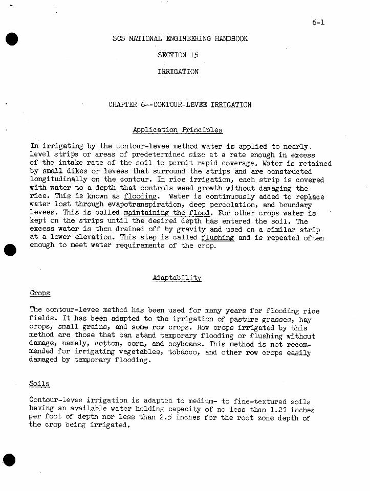
Application Principles
In i r r i ga t i ng by the contour-levee method water is applied t o nearly leve l s t r i p s or areas of predetermined s i z e a t a r a t e enough i n excess of the intake r a t e of the s o i l t o permit rapid coverage. Water is retained by s m a l l dikes o r levees t h a t surround the s t r i p s and a re constructed longitudinally on t he contour. In r i c e i r r iga t ion , each s t r i p i s covered with water t o a depth t h a t controls weed growth without damaging the r i ce . This i s known as flooding. Water i s continuously added t o replace water l o s t through evapotranspiration, deep percolation, md boundary levees. This is called maintaining the flood. For other crops water is kept on the s t r i p s u n t i l t he desired depth has entered the s o i l . The excess water is then drained off by gravi ty and used on a similar s t r i p a t a lower elevation. This s tep is cal led f lushing and is repeated often
a enough t o meet water requirements of the crop.
Adaptability
crops
The contour-levee method has been used f o r many years f o r flooding r i c e f i e l d s . It has been adapted t o the i r r i ga t i on of pasture grasses, hay crops, small grains, and some row crops. Row crops i r r i ga t ed by t h i s method are those t h a t can stand temporary flooding or f lushing without damage, namely, cotton, corn, and soybeans. This method is not recom- mended f o r i r r i ga t i ng vegetables, tobacco, and other row crops ea s i l y damaged by temporary flooding.
So i l s
Contour-levee i r r i g a t i o n i s adapted t o medium- t o fine-textured s o i l s having an available water holding capacity of no l e s s than 1.25 inches per foo t of depth nor l e s s than 2.5 inches f o r the root zone depth of t h e crop being i r r iga ted .

10 20 30 50 70 100 200 3W 500 7m 1m0 2WO 3000 5WO
TIME (MINUTES)
Figure 6-1.--Accunnrlated intake f o r i r r i ga t i on by the contour-levee method.
So i l intake r a t e s f o r t he desired ne t depth of application should not exceed those upper limits shown i n f i gu re 6-1. For example, i f a 3-inch application were planned f o r cotton, t he intake opportunity time should not be l e s s than 300 minutes. Intake r a t e s f o r contour-levee i r r i g a t i o n a re shown i n l oca l i r r i g a t i o n guides where they are known. Otherwise, they a re measured by the cylinder-infi l trometer method.
Because of the d i f f i c u l t y of maintaining the flood on s o i l s planted t o r ice , they should contain a r e s t r i c t i v e layer with a permeability r a t e of 0.02 inch per hour o r l ess .
Topography
For t h i s method, bes t r e s u l t s a re obtained where slopes do not exceed 0.5 percent. Greater slopes, however, can be reduced by land leveling. Where leveling i s required, the s o i l must be deep enough t o permit leveling without undue lo s s of productivity.
If contour levees m e used f o r i r r i ga t i ng row crops, the slope i n the direct ion of row drainage becomes a l imit ing fac tor . The maxirmun prac t i - c a l slope i s t h a t which w i l l not r e s u l t i n erosion from storm runoff. In areas where t h i s method i s now being used, slope ranges from 0.05 t o 0.3 percent depending on e rod ib i l i t y of t he s o i l . The minimum slope i s t h a t which w i l l provide adequate drainage, usually 0.05 t o 0.15 percent. Slopes mst be within these l im i t s o r mst be obtainable a t reasonable cos t by landing leveling.
Climate
The contour-levee method can be used successfully f o r i r r i ga t i ng r i c e and close-growing crops i n any climate t o which these crops are adapted, provided the prerequis i tes regarding s o i l and topography can be met. Levees are usually temporary f o r row crops and are usually not b u i l t

u n t i l the crop needs t o be i r r i ga t ed f o r t h e f i r s t time so t h a t they w i l l not i n t e r f e r e with operation of t h e cu l t iva t ing equipment. In humid areas where t h i s method i s common f o r i r r i g a t i n g row crops, r a i n f a l l usually is adequate during t he ear ly growing season and i r r i g a t i o n i s not required u n t i l cu l t iva t ion has been completed. When cu l t iva t ion becomes necessary a f t e r an i r r iga t ion , t he levees a re plowed down by the cu l t iva t ing equipment. They a r e then r e b u i l t t o make maximum use of subsequent r a i n f a l l . In areas where i n su f f i c i en t r a i n f a l l during t he ea r ly growing season would require frequent reconstruction of levees, t h e contour-levee method i s not recommended f o r i r r i g a t i n g row crops.
Advantages
The contour-levee method has several advantages.
(1) It permits t h e i r r i g a t i o n of low-intake-rate s o i l s t h a t are d i f f i c u l t t o i r r i g a t e by other methods.
( 2 ) Maximum u t i l i z a t i o n of r a i n f a l l reduces seasonal i r r i g a t i o n require- ments.
( 3 ) Unif o m d i s t r i bu t i on of water and high f ield-application eff ic iency are eas i ly obtained.
( 4 ) Since t h e same system removes excess storm runoff, adequate drainage can be provided a t l i t t l e ex t ra expense. This is very important i n areas of hizh r a i n f a l l .
( 5 ) In s t a l l a t i on cos t s depend largely on t he amount of land preparation required. Where t he u n i t volume of level ing i s moderate, i n s t a l l a - t i on costs a r e low compared with most other methods.
( 6 ) Simple, e a s i l y operated controls permit handling la rge i r r i ga t i on streams with minirmun labor. One i r r i g a t o r can usual ly handle up t o 300 acres including pump attendance.
Limitations i n Use
Some l imita t ions and disadvantages of the method are:
(1) It is r e s t r i c t ed t o i r r i g a t i n g crops t h a t can stand temporary flood- ing f o r 12 hours or more without damage.
( 2 ) It cannot be used successfully on s o i l s having moderate t o rapid in take charac te r i s t i cs ( f i g . 6-1).
( 3 ) Some degree of land leveling i s usual ly required. ( 4 ) Large i r r i g a t i o n streams a re required. ( 5 ) Light ne t applications a re d i f f i c u l t t o make e f f i c i en t l y . ( 6 ) Levees, ditches, and s t ruc tures need frequent maintenance.

Land Preparation Requirements
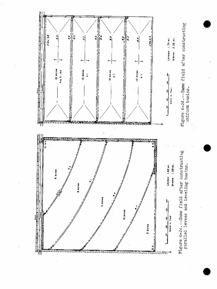
Contour levees require some land preparation. Figures 6-2a, b, c, d i l l u s t r a t e t he d i f f e r en t degrees t o which a typ ica l 40-acre f i e l d can be prepared f o r t h i s method of i r r i ga t i on . Though these i l l u s t r a t i o n s were prepared f o r i r r i g a t i n g r i ce , they a re adaptable t o the i r r i g a t i o n of f i e l d and forage crops.
Without land preparation, long levees, di tches, and canals m a y be re- quired; water cannot be applied uniformly or e f f i c i en t l y ; water manage- ment i s d i f f i c u l t ; and production costs, especia l ly f o r labor, a re high. Figure 6-2a shows t he topography of a f i e l d before land preparation. It a l so shows t he extent of levees and drains i f levees were constructed a t a v e r t i c a l i n t e rva l of 0.2 foo t on t h e o r ig ina l topography.
Eliminating minor surface i r r e g u l a r i t i e s improves t h e topography of t he f i e l d . Smoothing, usual ly with a land plane, permits laying out a usable i r r i g a t i o n and drainage system, but levees, di tches, and canals a r e s t i l l too long and basins a r e i r r egu l a r i n shape and var iable i n size, making e f f i c i e n t i r r i g a t i o n d i f f i c u l t ( f i g . 6-2b ) . For more e f f i c i e n t operation of planting, cul t ivat ing, and harvesting equipment and f o r b e t t e r water management, t he levees should be p a r a l l e l and the basins of uniform width ( f i g . 6-2c). The levees can be staked p a r a l l e l on approximate contours first and each basin then leveled t o a uniform plane, o r t he e n t i r e f i e l d can be leveled f i r s t and the levees then staked p a r a l l e l and on the contour. This r e s u l t s i n increased water-use efficiency, high crop yields, and reduced production costs.
a An addi t ional refinement t h a t fu r ther increases water-use eff ic iency and f a c i l i t a t e s water management consis ts of dividing t he f i e l d i n t o un i t s o r basins of equal s i z e and shape by levees t h a t a r e s t r a i g h t and pa ra l l e l . The levees can be constructed f i r s t and t he basins then leveled and each t rea ted as a separate f i e ld , or the e n t i r e f i e l d can be leveled f i r s t and t he levees constructed afterward. Where land i s leveled by water leveling, l eve l basins r e su l t . The slope required f o r drainage i s obtained by plowing t he basin toward t h e center, thus building up a r idge ( f i g . 6-2d).
Where conventional land leveling i s used, t he basins usually are sloping planes (p. 6-15). Neither type of basin i s considered t o have an advantage over the other.
Tnese basins, equal i n s i z e and shape, while more expensive t o construct, increase water-use eff ic iency and reduce labor costs .

I o loo rpo roo .oo rm L a v a a s r 5 . 6 5 mi.
Scola I n Faat D r o i n r r 2 . 42 mi.
Figure 6-2a. --Typical topography of a 40-acre f i e l d t o be i r r i g a t e d by t h e contour-levee
1- w 0 400 l o o L l v a e r ~ 3 . 4 mi.
Scal. I n F1.l D r o i n a z 1.6 ml.
Figure 6-2b.--Same f i e l d showing contour levees a f t e r land smoothing.
method showing levees &d dra ins i f land were not smoothed o r leveled.

Detailed Investigations
Soi ls - A detai led s o i l map of the area t o be i r r iga ted i s a prerequis i te t o planning a contour-levee system. The intake charac te r i s t ics of each s o i l must be known. If they cannot be obtained from the loca l i r r i ga t ion guide, they w i l l have t o be measured by the cylinder-infiltrometer method. For s o i l s on which r i c e is t o be i r r iga ted , the permeability r a t e of the r e s t r i c t i ng layer must be known.
The available water holding capacity of the s ign i f ican t layers of each s o i l should be lmown. These a re usually obtained from the loca l i r r i ga - t i on guide.
Topography
A topographic map of the area t o be i r r iga ted f a c i l i t a t e s planning the contour-levee system. Information on the map should include, i n addition t o contour l ines , the location and elevation of the water source and drainage out le t . The map should a lso show any pipelines, drains, power- l ines , structures, roads, or other important physical features.
The topographic map can be based on e i ther a conventional or gr id survey. Aerial photographs may serve the purpose of a topographic map i f old contour levees a r e v i s ib le and i f they adequately describe the topog- raphy
Water Supply
Dependable stream s izes available f o r i r r i ga t ion should be measured or estimated. The available stream sizes determine the nurriber of acres of a given crop t h a t can be i r r i ga t ed (p . 6-9).
The qual i ty of the water with respect t o i t s intended use should be determined.
Layout of Levee S;ysterns
If an adequate contour map i s available, the levee system can be l a id out on the map before making the layout on the ground. This saves time and e f f o r t i n the f i e l d .
The f i r s t s tep i s t o determine the maxim-s ize un i t or basin t h a t can be i r r iga ted with the stream s i z e available (sample calculations 3 and 4).
The shape of t he basins i s important. To prevent overtopping of the levees, the dimension of any basin i n the direct ion of the prevail ing wind should not exceed about 400 f ee t . Length of the basin may be r e s t r i c t ed
@ by drainage requirements. The channel above the levee along the lower
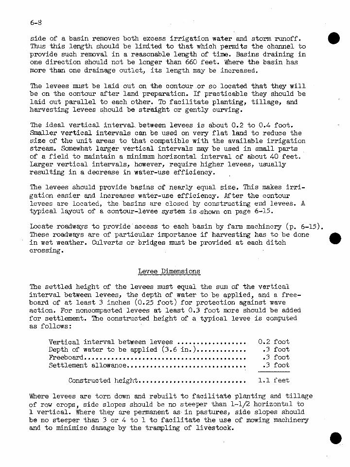
side of a basin removes both excess i r r iga t ion water and storm runoff. Thus t h i s length should be limited t o tha t which permits the channel t o provide such removal i n a reasonable length of time. Basins draining i n one direction should not be longer than 660 fee t . Where the basin has more than one drainage outlet , i ts length may be increased.
The levees mst be la id out on the contour or so located tha t they w i l l be on the contour a f t e r land preparation. If practicable they should be l a id out para l le l t o each other. To f a c i l i t a t e planting, t i l l age , and harvesting levees should be s t ra ight or gently curving.
The ideal ve r t i ca l in te rva l between levees is about 0.2 t o 0.4 foot. Smaller ve r t i ca l intervals can be used on very f l a t land t o reduce the s i ze of the uni t areas t o tha t compatible with the available i r r iga t ion stream. Somewhat larger ver t i ca l intervals m a y be used i n small pasts of a f i e l d t o maintain a m i n i m horizontal in te rva l of about 40 f ee t . Larger ve r t i ca l intervals, however, require higher levees, usually resulting i n a decrease i n water-use efficiency.
The levees should provide basins of nearly equal size. This makes irri- gation easier and increases water-use efficiency. After the contour levees are located, the basins are closed by constructing end levees. A typical layout of a contour-levee system is.shown on page 6-15.
Locate roadways t o provide access t o each basin by farm machinery (p. 6-15). These roadways are of par t icular importance i f harvesting has t o be done i n wet weather. Culverts o r bridges must be provided a t each di tch crossing.
Levee Dimensions
The se t t led height of the levees must equal the sum of the ve r t i ca l in te rva l between levees, the depth of water t o be applied, and a free- board of a t l e a s t 3 inches (0.25 foo t ) f o r protection against wave action. For noncompacted levees a t l eas t 0.3 foot more should be added f o r settlement. The constructed height of a typical levee i s computed as follows:
.................. Vertical in te rva l between levees 0.2 foot Depth of water t o be applied (3.6 in. ). ............ .3 foot Beeboasd.......................................... .3 foot Settlement allowance............................... .3 foot
Constructed height ............................ 1.1 f e e t
Where levees are torn down and rebui l t t o f a c i l i t a t e planting and t i l l a g e of row crops, s ide slopes should be no steeper than 1-1/2 horizontal t o 1 vert ical . Where they are permanent as i n pastures, s ide slopes should be no steeper than 3 or 4 t o 1 t o f a c i l i t a t e the use of mowing machinery and t o minimize damage by the trampling of livestock.
A drainage channel no l e s s than 0.5 foo t deep with s i de slopes no steeper than 1-1/2 hor izontal t o 1 v e r t i c a l i s provided along the upper s i de of each levee. The mater ia l removed from t h e drainage channel i s used t o build the levee (p. 6-15). Temporary levees a r e usually b u i l t with border plows o r border disks and wider, more permanent levees with blade graders.
I r r iga t ion Stream Sizes
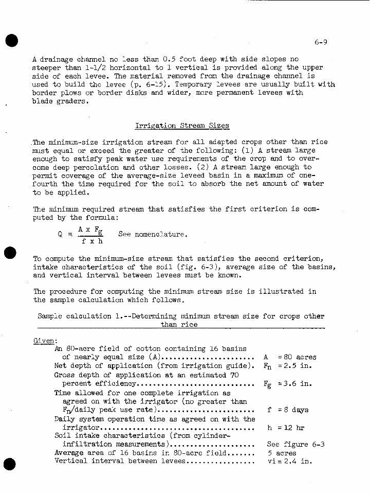
.The minimum-size i r r i g a t i o n stream f o r a l l adapted crops other than r i c e must equal or exceed the g rea te r of t he following: ( 1 ) A stream la rge enough t o s a t i s f y peak water use requirements of the crop and t o over- come deep percolation and other losses. ( 2 ) A stream la rge enough t o permit coverage of t he average-size leveed basin i n a maximum of one- four th t he time required f o r t h e s o i l t o absorb the ne t amount of water t o be applied.
The m i n i m required stream t h a t s a t i s f i e s t h e f i r s t c r i t e r i o n is com- puted by t he formula:
A x Fg Q = See nomenclature.
f x h
To compute t he minimum-size stream t h a t s a t i s f i e s the second c r i t e r ion , in take cha rac t e r i s t i c s of t h e s o i l ( f i g . 6-3), average s i z e of t h e basins, and v e r t i c a l i n t e rva l between levees must be known.
The procedure f o r computing t h e minimum stream s i z e i s i l l u s t r a t e d i n t h e sample calcula t ion which follows.
Sample calcula t ion 1.--Determining minimum stream s i z e f o r crops other than r i c e
Given : An 80-acre f i e l d of cotton containing 16 basins
of nearly equal s i z e ( A ) ....................... Net depth of application (from i r r i g a t i o n guide). Gross depth of application a t an estimated 70
percent efficiency.. ........................... Time allowed f o r one complete i r r i g a t i o n as
agreed on with t h e i r r i g a t o r (no grea te r than ~ d d a i l y peak use r a t e ) . .......................
Daily system operation time as agreed on with t he irrigator.. . . . . . . . . . . . . ........................
Soi l in take cha rac t e r i s t i c s (from cylinder- i n f i l t r a t i o n measurements ). ....................
Average area of 16 basins i n 80-acre f i e ld . . . . . . . Ver t ical i n t e rva l between levees . . . . . . . . . . . . . . . . .
A = 80 acres Fn = 2.5 in.
Fg = 3 . 6 in .
f = 8 days
See f igure 6-3 5 acres v i = 2.4 in .

Find : - The minimum stream s i z e ( Q ) t ha t s a t i s f i e s the two c r i t e r i a .
Procedure : Compute the minimum stream s i z e required t o sa t i s fy the f i r s t cr i ter ion as follows :
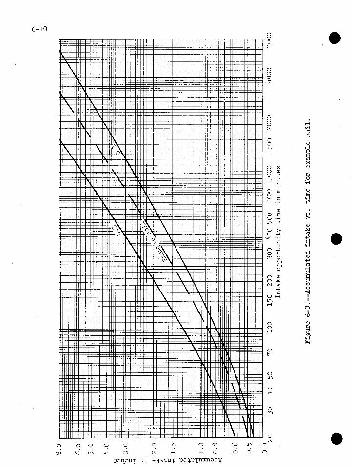
Using the example s o i l curve shown i n f igure 6-3, find the time (T,) required f o r the net depth of application ( F ~ = 2.5 inches) t o i n f i l - t r a t e the so i l . Tn is 580 minutes.
Allowing one-fourth of the time (Tn), or 145 minutes, t o cover an average- s i ze basin, f ind the average depth of water tha t i n f i l t r a t e s the s o i l during this period. Water i n f i l t r a t e s the s o i l only along the lower side of the basin during Tn/4; there is no i n f i l t r a t i o n along the upper side. The basin i s covered f o r 145 minutes along the lower s ide and f o r zero minutes along the upper s ide with an average coverage time of 72-1/2 minutes. Using f igure 6-3, find the depth of water tha t i n f i l t r a t e s the s o i l i n 72-1/2 minutes. This is 0.76 inch.
To t h i s average depth of in f i l t r a t ion add the average depth of water over the basin a t the end of t h i s period. Since the ve r t i ca l in te rva l 0 between levees i s 2.4 inches, the water i s tha t deep along the lower s ide of the basin and has no depth along the upper side. Thus the average depth is one-half of the ve r t i ca l in te rva l ( v i ) or 1.2 inches.
Compute the minimum stream s ize required t o sa t i s fy the second cr i te r ion as follows:
Required stream s i z e per acre ( q ) :
(0.76 in,+ 1.2 in.) x 60 4 = = 0.811 acre-in. per hr
U-5 min = 0.811 cf s per acre
Required t o t a l stream s i ze ( Q ) :
Q = 5 acres x 0.811 c f s per acre = 4.06 cfs - Since the second cr i te r ion requires a greater stream size, the value 4.06 cubic f e e t per second i s used.
In r i c e i r r igat ion, there a re three c r i t i c a l operations, any one of which may determine the required i r r iga t ion stream size: ( I ) Flushing, which usually follows seedbed preparation and dry planting. The i r r iga t ion stream must be large enough t o cover a basin i n one-fourth the time re- quired fo r the s o i l t o absorb the net amount of water applied, (2 ) Flood- ing, which is s ta r ted when the plants are about 8 t o 10 weeks old and are

using water a t a maxim ra te . The i r r iga t ion stream must be large enough t o flood the en t i re design area t o a predetermined depth--usually 3 t o 4 inches--in the time required f o r depletion,at the peak rate,of one-half the available moisture i n the root zone of the so i l . (3 ) Main- taining the flood u n t i l about 2 weeks before harvest. The i r r iga t ion stream must be large enough t o sa t i s fy peak-period consumptive use and overcome deep percolation losses.
The procedure used for determining minimum required stream size for each of these c r i t i c a l operations is i l l u s t r a t ed i n the sample calculation which follows:
Sample calculation 2.--Determining minimum stream s i ze for r i ce i r r iga t ion
Given : An 80-acre f i e l d of r i c e containing 16 basins of
nearly equal s ize ( A ) . ......................... A = 80 acres Available water holding capacity of s o i l a t root
zone depth (18 in,) ............................. = 3.6 in . Saturated moisture capacity of s o i l a t root zone
depth............ .............................. = 7.35 in. Permeability of res t r ic t ing layer ................ = 0.002 in/hr Net depth of application (from i r r iga t ion guide). Fn = 1.8 in. Soi l intake character is t ics (from cylinder-
inf i l trometer measurements ). ................... See f igure 6-3 ................. Peak-period consumptive-use r a t e u = 0.3 i d d a y Vertical in te rva l between levees............,.... v i = 2.4 in ,
Find : - The minimum stream s i ze (9) required f o r flushing, flooding, and maintaining the flood.
Procedure : For flushing.--Using f igure 6-3, f ind the time (Tn) required f o r the net depth of application ( F ~ = 1.8 inches) t o i n f i l t r a t e the so i l . Tn i s 345 minutes.
Allowing one-fourth of Tn, or 86 minutes, t o cover an average-size basin ( 5 acres), find. the average depth of water .that i n f i l t r a t e s the s o i l during t h i s period. This depth i s 0.62 inch ( f ig . 6-3). To t h i s average depth of in f i l t r a t ion , add the average depth of water over the surface of the basin a t the end of t h i s time period. This average depth i s equal t o one-half the ve r t i ca l d i s tmce between the levees or one-half of 2.4 inches = 1.2 inches.
Required stream s i ze per acre (q) :
(0.62 in. + 1.20 in3 60. = 1.27 acremine pep hr 9 = 86 min = 1.27 cfs per acre
Required t o t a l stream s i ze ( Q) : Q = 5 acres x 1.27 c f s per acre = - 6.35 c f s
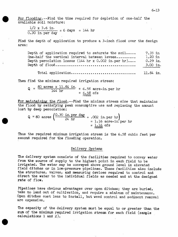
For floodin<. --Find the time required f o r depletion of one-half the available s o i l moisture :
1/2 x 3.6 in . = 6 days = 144 h r 0.30 in. per day
Find the depth of application t o produce a 3-inch flood over the design area :
Depth of application required t o sa tura te the soi l . . . . . 7.35 i n One-half the ve r t i ca l in te rva l between levees.......... 1.20 i n Depth percolation losses (144 h r x 0.002 in. per hr). ... 0.29 in . Depth of flood.......................................... 3.00 i n .
................................. Total application 11.84 in.
Then f ind the minimum required i r r i ga t ion stream:
Q = 80 acres = 6 58 acre-in, per hr 144 hr
= - 6.58 c f s
For maintaining the flood.--Find the minimum stream s i z e tha t maintains the flood by sat isfying peak consumptive use and replacing the a ~ ~ l ~ u n t
l o s t by deep percolation:
0.30 in. per day Q = 80 acres ( 24hr + .002 in. per hr
= 1.16 = 1.16 c f s - -
Thus the required minimum i r r iga t ion stream i s the 6.58 cubic f e e t per second required f o r the flooding operation.
Delivery Systems
The delivery system consis ts of the f a c i l i t i e s required t o convey water from the source of supply t o the highest point i n each f i e l d t o be i r r igated. The water may be conveyed above ground l eve l i n elevated f i e l d ditches o r i n low-pressure pipelines. These f a c i l i t i e s a l so include the structures, valves, and measuring devices required t o control and d i r e c t the water t o the individual f i e l d s as needed and a t the designed r a t e of flow.
Pipelines have obvious advantages over open ditches; they a re buried, take no land out of cult ivation, and require a minimum of maintenance. Open ditches cost l e s s t o i n s t a l l , but weed control and sediment removal a re expensive.
The capacity of the delivery system must be equal t o o r greater than the sum of the minimum required i r r i ga t ion stream fo r each f i e l d (sample calculations 1 and 2 ).
6-14
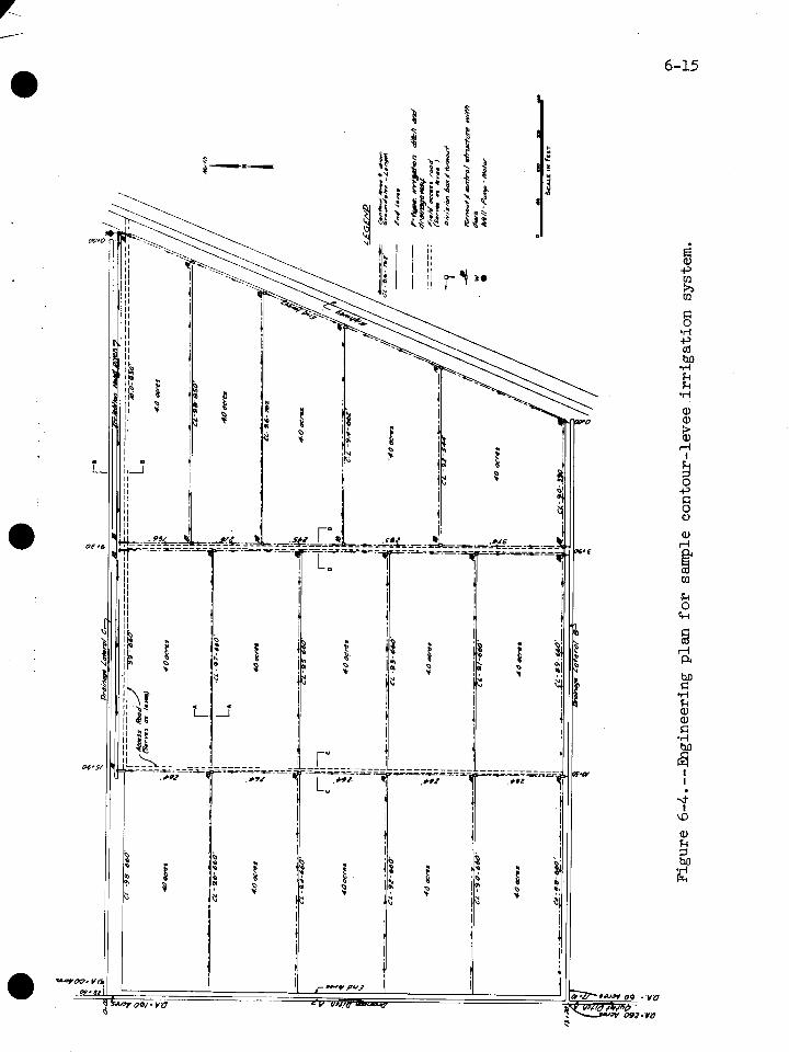
In the s m p l c plan no deli7rery system is shown since the source of sup- ply, a well, is located a t the highest point i n the f i e l d ( f ig . 6-4). The i r r i ga t ion supply d i tch along the north boundary of the f i e l d i s considered a pa r t of the application system.
Application Systems
The appl.ioation system consists of the f a c i l i t i e s required t o d i s t r i bu te and apply water on a l l pa r t s of a f i e l d . These f a c i l i t i e s may include open ditches, pipelines, levees, turnouts, control structures, culverts, and other devices.
An i r r i ga t ion head d i tch or pipeline i s used t o convey water t o the highest basin i n each ser ies . Water is turned in to these upper basins thxough turnouts i n head ditches or through valves i n pipelines ( f i g . 6-5 ).
The head d i tch consists of two pa ra l l e l levees or dikes. The construc- t i on material may be borrowed from land-grading operations, from nearby borrow areas, or from the center area between the levees themselves. If levee material can be borrowed elsewhere economically and conveniently, center borrow ditches should not be used. Center borrow ditches must usually be larger than required f o r adequate capacity t o obtain enough material f o r construction of the levees. Ditches of t h i s type are neces- s a r i l y wide and take up space t h a t otherwise might be cult ivated.
Since the system operates by gravity, water is conveyed above ground surface and a head of not l e s s than 0.5 foo t must be provided a t the turnouts. The top of the levees forming the head d i tch must be a t l e a s t 1.5 f e e t above the highest pa r t of the i r r iga ted area. The head d i tch should have s tab le s ide slopes, usually 1-1/2 horizontal t o 1 ver t ica l .
Several types of turnouts are used t o introduce water i n to the basins. One of the most popular consis ts of a pipe with a gate on the upstream end. A 10-foot section of corrugated metal pipe with an inexpensive l i g h t s t e e l gate i s easy t o i n s t a l l and has proven very sat isfactory. Pipe diameter i s determined by the design r a t e of flow and the head provided t o obtain t h a t flow. Several types of turnout t h a t have proven s a t i s - factory a re shown i n chapter 3.
Inside the i r r iga ted area, water i s usually conveyed from the head di tch or pipeline t o the lower basins by V-type i r r i ga t ion ditches which also serve as drainageways. The capacity of these ditches must be equal t o the minimum required i r r i ga t ion stream or t o the computed drainage re- quirements, whichever is the greater. They should be a t l e a s t 0.5 foot deeper than the V-type drains along the upper s ides of the contour levees or a minimum of 1 foot.
There should be roadways between each se r i e s of basins f o r easy access t o a l l par t s of the f i e l d . Waste material placed between two pa ra l l e l


V-type i r r iga t ion ditches can be used t o form the roadway. The roadway also acts as an end levee and must be equal i n height t o the contour levees. Slopes should be no steeper than 1-1/2 horizontal t o 1 ver t ica l except tha t i n pastures they should be no steeper than 3 or 4 t o 1. (See section D-D, .figure 6-5. )
To retain, control, and eventually remove the i r r iga t ion water sui table control structures must be placed i n the i r r iga t ion ditches under each contour levee. Several types of structures have been developed. One is a concrete pipe culvert with an adjustable s t e e l plate a t i t s upper end ( f i g . 6-5). Another is a sheet metal s t ructure tha t has flashboards f o r water control. In some levees fixed-crest weirs made of sheet metal or other sui table material are added as a fur ther control.
The capacity of any control s t ructure should be equal t o tha t of the di tch i n which it is placed. The s t ructure should be designed t o operate under a head not exceeding 0.5 foot. If a pipe is used, the normal diameter should be no l e s s than 10 inches.
Drainage Requirements
The i r r iga t ion application system provides adequate drainage within the design area. Providing an adequate out le t and preventing runoff from adjacent areas entering the i r r iga ted area are the other drainage problems.
The out le t i s usually a trapezoidal channel able t o provide adequate drainage f o r both the i r r iga ted area and any other area it may serve. The out le t or a channel l a t e r a l t o it serves the lowest basin i n each ser ies . Additional channels must be provided around the boundaries of the drainage area where needed to prevent the entrance of runoff from higher areas ( f ig . 6-4) . In computing the capacity of the out le t channel and i ts l a t e ra l s pro- vide adequate drainage for the l eas t water-tolerant crop grown i n the rotation.
Operation
The method of operation varies with the crop being i r r igated and with the owner's preference f o r operating time. The usual methods follow.
Crops Other Than Rice
Individual basins i n a ser ies are i r r igated consecutively, beginning with the highest and ending with the lowest. A l l control structures i n the i r r iga t ion di tch serving a ser ies of basins are closed and water from the head di tch or pipeline is then turned in to the highest basin i n the ser ies . The i r r iga t ion stream discharges in to the f i r s t basin

u n t i l the gross application depth plus the depth needed t o cover the basin has been applied. Then the s t ructure controlling t h i s basin i s pa r t i a l ly opened, allowing the i r r iga t ion stream t o flow in to the second or next lower basin. The water flows in to the second basin u n t i l the gross application has been applied. Then the th i rd basin i s flooded i n similar manner. This process is continued downstream u n t i l the gross application for the ser ies has been applied.
After water has remained on the highest basin u n t i l the desired depth has in f i l t r a t ed the so i l , the control structure i n t h i s basin i s com- pletely opened and the water drains off and flows onto the next lower basin. This process is continued u n t i l a complete ser ies of basins i s irrigated. This operation may be undertaken during daylight only (sample calculation 3 ) or may be a contipuous one. Continuous operation i s the more e f f i c i en t since only the excess water from the l a s t or lowest basin i n a ser ies need be drained off as waste.
Other ser ies of basins i n the f i e l d a re then i r r iga ted i n l i k e manner. When the f i e l d i s not being i r r igated, a l l control s t ructures i n the i r r iga t ion ditches are l e f t open f o r drainage.
Operation f o r Rice
In r i c e i r r iga t ion , there are four operations: moisture control for germination, flooding, maintaining the flood, and removing the flood.
Moisture control f o r germination.--Rice is seeded e i ther by d r i l l i ng dry o r by broadcasting in to water from an airplane. When d r i l l i n g is followed by a period of dry weather, flushing i s needed t o germinate the seed or t o prevent loss of young seedlings through lack of moisture. The flush- ing process fo r r i c e is the same as for other crops.
When seeding is done from the a i r , the basins are flooded t o a shallow depth before seeding. As soon as the r i c e sprouts, the water is drained off t o hasten growth of the r i c e plants and permit them t o develop deep root sys tern . Flooding.--Each basin i s flooded with water so as t o provide weed con- t r o l without damage t o the r i c e plants.Rice is normally flooded twice during the growing season. About 3 t o 4 weeks a f t e r seeding the basins a re flooded t o a shallow depth t o control weeds and t o provide adequate moisture. This flood is held on the basins f o r about 2 weeks a f t e r which it may be drained off and the s o i l surface allowed t o dry out. ~ r y i n g helps control root maggots, algae, and fungi. It also provides a favor- able period for applying f e r t i l i z e r and permits the r i c e straw t o s t i f f e n and r e s i s t lodging.
The second flooding comes about 7 t o 9 weeks a f t e r seeding. Water re- quirements a re high because t N s i s during the peak consumptive-use period. Each basin is flooded t o a depth of 3 inches or more and the flood is maintained f o r 9 t o 10 weeks or from 2 t o 3 weeks before harvest .
Each s e r i e s of basins is flooded separately, one s e r i e s being com- p l e t e ly flooded before another i s s ta r ted . When the design depth of f lood has been reached on the f i r s t basin, the water i s turned i n to the next lower basin and t h e process repeated downstream u n t i l a l l basins i n a s e r i e s a r e flooded. The design depth of f lood is maintained i n each basin by using sheet metal weir s t ruc tures i n t he levees o r by manipu- l a t i ng the turnouts o r control s t ruc tures i n t h e i r r i g a t i o n ditch.
When one s e r i e s of basins has been completely flooded, t he other s e r i e s a r e then flooded i n l i k e manner.
Nlaintaining the flood.--The design depth of flood i s maintained on a l l I
basins simultaneously by adding water a t the r a t e needed t o overcome losses due t o evaporation, t ranspira t ion, deep percolation, and seepage through t h e levees.
Removing t he flood.--Near t he end of t he flood maintenance period the water is cut off and the flood allowed t o i n f i l t r a t e t h e s o i l p r o f i l e so t h a t only a minimum remains t o be drained off as waste. A l l water should be removed from the f i e l d about 2 weeks before the r i c e harvest t o provide a dry surface f o r harvesting machinery.
Water Use Efficiency
A s i n other surface methods of i r r i ga t i on , t he eff ic iency of water use obtained with t h e contour-levee method depends on the physical char- a c t e r i s t i c s of t h e so i l , adequacy of land preparation, planning and construction of t he system, and care exercised i n i t s operation. Assum- ing good planning, construction, and operation, 65 t o 70 percent eff ic iency may be obtained i n i r r i ga t i ng crops other than r i c e . D i f - f e r en t degrees of eff ic iency a re obtainable f o r t he th ree separate operations used i n i r r i g a t i n g r i c e . When these w e averaged, the over- a l l ef f ic iency i s 70 t o 80 percent.
Sample Design Problems
The design procedure fo r contour-levee i r r i g a t i o n systems i s presented here by sample calculations. Those se lected consis t of designing com- bined contour-levee i r r i g a t i o n and drainage systems--one f o r cotton and one fo r r ice-- for a 60-acre f i e l d i n the de l t a area of Louisiana ( f i g . 6-4). The surface of the f i e l d has been improved by land leveling. The design procedure fo r i r r i ga t i ng cotton is presented i n sample cal- cula t ion 3 and for r i c e i n sample calcula t ion 4 ,

Sample calcula t ion 3.--Designing contour-levee i r r i g a t i o n and drainage system f o r cotton i r r i ga t i on
Given : A 60-acre f i e l d of cotton (A) . . ............... A = 60 acres Available stream s i z e = 1,500 gpm.. .......... Q = 3.33 c f s ...................... Net depth of application Fn = 2.5 in. Maximum time allowed f o r one i r r i ga t i on . ...... f = 8 days ........... Hours of operation (daylight only). h = 12 t o 14 hr S o i l intake characterist ics. . . . . . . . . . . . . . . . . . . See f i gu re 6-3 Vert ical i n t e rva l between levees, 0.2 ft . . . . . . v i = 2.4 in.
Find : - Minimum required stream per acre, q Maximum s i z e of basin Required number of basins Time required f o r one i r r i g a t i o n Application eff ic iency I r r i ga t i on d i tch s i ze s Drainage requirements Turnout and culver t s i z e s
Procedure : In f igure 6-3 f ind the time (T~) required f o r the ne t depth of applica- t i on (Fn = 2.5 in.) t o i n f i l t r a t e t he s o i l . Tn i s 580 minutes.
Using f igure 6-3 and allowing one-fourth Tn, o r 145 minutes, t o cover one u n i t o r basin, f ind the average depth of water t h a t i n f i l t r a t e s the s o i l
145 during t h i s period. Average time = - =72.5 minutes. This depth i s 0.76 inch. 2
Average depth of water i n surface storage a t t h e end of time period
- Tn is 112 v i or (y ) or 1 . 2 inches 4
Minimum required stream s i z e per acre ( q ) :
(0.76 in.+ 1.2 in,) 60 (I = = 0.811 acre-in. per h r
145 min (0.811 c f s per ac re ) -
Maximum s i z e of basin or un i t area:
Available stream s i z e - - 3.33 c f s Minimum stream s i z e per acre 0.811 c f s per acre
= 4.11 acres
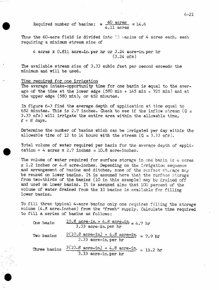
Required number of basins : = 60 acres = 14, 6 4.11 acres
Thus the 60-acre f i e l d is divided in to 7 s [.,asins of 4 requiring a minimum stream s i z e of
acres
4 acres x 0.811 acre-in. per hr or 3.24 acre-in, per hr (3.24 c f s )
each, each
The available stream s i z e of 3.33 cubic f e e t per second exceeds the minimum and w i l l be used.
Time required f o r one i r r i pa t ion The average intake-opportunity time f o r one basin is equal t o the aver- age of the time a t the lower edge (580 min + 145 min = 725 min) and a t the upper edge (580 min), or 652 minutes.
In f igure 6-3 f ind the average depth of application a t time equal t o 652 minutes. This is 2.7 inches. Check t o see i f the inflow stream (Q = 3.33 c f s ) w i l l i r r i g a t e the e n t i r e area within the allowable time, f = 8 days.
Determine the number of basins which can be i r r iga ted per day within the allowable time of 12 t o 14 hours with the stream (Q = 3.33 c f s ) .
Total volume of water required per basin f o r the average depth of appli- cation = 4 acres x 2.7 inches = 10.8 acre-inches.
The volume of water required f o r surface storage i n one basin is 4 acres x 1.2 inches or 4.8 acre-inches. Depending on the i r r i ga t ion sequence and arrangement of basins and ditches, some of the S L ~ T E ~ C ~ stdJ7age m ; g be reused on lower basins. It is assumed here %fiat the surf ace :torage from two-thirds of the basins (10 i n t h i s example! may be drai-ned off and used on lower basins. It is assumed also tha t 100 percent of the volume of water drained from the 10 basins Is available f o r f i l l i n g lower basins.
To f i l l three typical 4-acre basins only one requires f i l l i n g the storage volume (4.8 acre-inches ) from the f l f reshf l supply. Calculate time required t o f i l l a s e r i e s of basins as follows :
One basin 10.8 acre-in. + 4.8 acre-in. = 4.7 hr 3.33 acre-in. per hr
Two basins 2(10.8 acre-in.) + 4.8 acre-in , 7.9 hr 3.33 acre-in. per hr
Three basins 3 (10.8 acre-in.) + 4.8 acre-in. = 11.2 hr 3.33 acre-in. per hr

6-22
The actual time t o complete an i r r i ga t ion of three basins depends on management of the drained wa.ter. The f i r s t basin can be drained of sur- face storage a f t e r 12.1 houm and the second 16.8 hours a f t e r water starts t o f i l l the f i r s t basin.
Thus three basins could be i r r iga ted within the allowable time, 12 t o 14 hours.
In f igure 6-4, each of the three segments of the f i e l d contains f i ve basins.
Each ser ies can be i r r iga ted i n 2 days--two basins i n 1 day and three the next. The 15 basins (60 acres) can be i r r iga ted i n 6 days, which i s within the allowable time, f = 8 days.
Determine f i e l d application efficiency i n percent ( E ) . Volume needed t o r e f i l l s o i l x 100
E = Volume actual ly applied
The volume needed t o r e f i l l . the s o i l i n one basin i s 4 acres x 2.5 inches,or 10 acre-inches.
Efficiency when two basins (8 acres) a re i r r iga ted :
E = ( 2 x 10 acre-in.) x 100 ( 2 x 10.8 acre-in,) + 4.8 acre-in.
- - - 20 x 100 = 76 percent 26.4
Efficiency when three basins (12 acres ) are i r r iga ted :
E = (3 x 10 acre-in,) x 100 (3 x 10.8 acre-in,) + 4.8 acre-in.
Average appli.cation efficiency f o r the 60-acre f i e l d :
3 x 8 acres (76 percent) + 3 x 12 acres (81 percent) 60 ames 60 acres
Average E = 0.4 (76 percent) + 0.6 (81 percent) = 79 percent
Since the time required t o apply the needed depth of water is within the time allowable and the f i e l d application efficiency i s within acceptable limits, the i r r i ga t ion phase of t he design is sat isfactory.
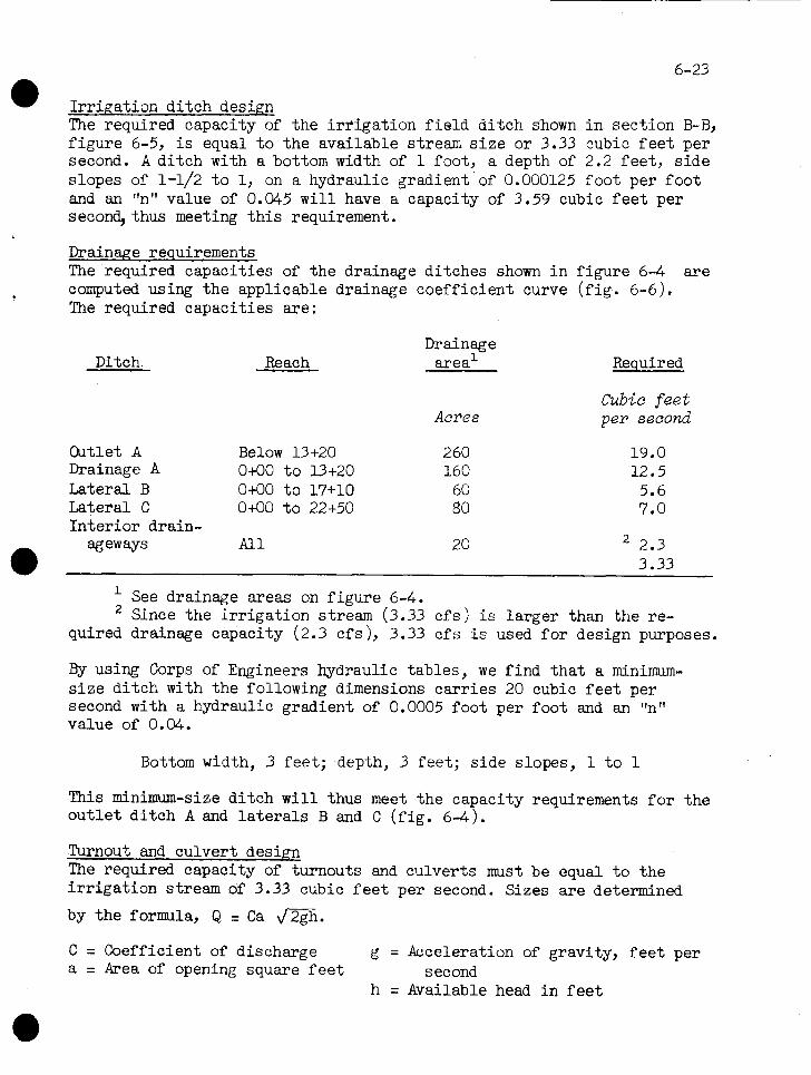
I r r i ga t i on d i t ch design The required capacity of t he i r r i g a t i o n f i e l d d i t ch shown i n s e c t i o n B-R, f i gu re 6-5, i s equal t o t he avai lable stream s i z e or 3.33 cubic f e e t per second. A d i t ch with a bottom width of 1 foot, a depth of 2.2 f ee t , s i de slopes of 1-1/2 t o 1, on a hydraulic gradient of 0.000125 foo t per f oo t and an "n'' value of 0.M5 w i l l have a capacity of 3.59 cubic f e e t per second, thus meeting t h i s requirement.
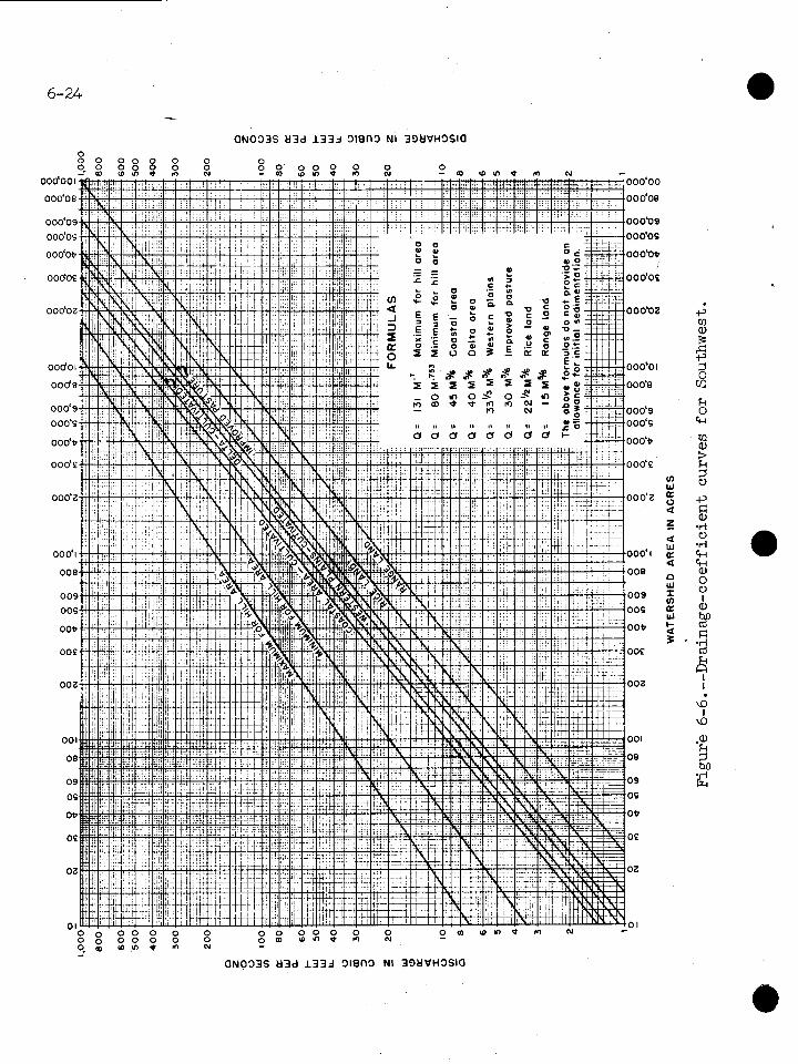
Drainage requirements The required capaci t ies of t he drainage di tches shown i n f i gu re 6-4 a r e computed using t h e applicable drainage coef f ic ien t curve ( f i g . 6-6). The required capaci t ies a re :
Drainage Ditch. Reach area1 Required
Acres
Cutlet A Below 13+20 2 60 Drainage A 0+00 t o 13+20 160 Latera l B 0+00 t o 17+10 60 Latera l C 0+00 t o 22+50 80 In t e r i o r drain-
ageways A l l 20
Cubic feet per second
See drainage areas on f i gu re 6-4. Since t he i r r i g a t i o n stream (3.33 c f s ) is l a rge r than t he re-
quired drainage capacity (2.3 c f s ), 3.33 c f s is used f o r design purposes.
By using Corps of Engineers hydraulic t ab les , we f ind t h a t a minimum- s i z e d i t ch with t he following dimensions ca r r i e s 20 cubic f e e t per second with a hydraulic gradient of 0.0005 foo t per f oo t and an "n" value of 0.04.
Bottom width, 3 f ee t ; depth, 3 fee t ; s i de slopes, 1 t o 1
This minimum-size d i t ch w i l l thus meet t he capacity requirements f o r the o u t l e t d i t c h A and l a t e r a l s B and C ( f i g . 6-4).
Turnout and cu lver t design The required capacity of turnouts and culver ts must be equal t o t he i r r i g a t i o n stream of 3.33 cubic f e e t per second. Sizes a r e determined
by t he formula, Q = Ca m h .
C = Coefficient of discharge g = Acceleration of gravity, f e e t per a = Area of opening square f e e t second
h = Available head i n f e e t
DISCHARGE IN CUBIC FEET PER SECOND
-

Try using an 19-inch concrete pipe, 10 f e e t long, with a square-cornered entrance operating under a head of 0.1 foot . The computation becomes:
Q = 0.81 x 1.767 J2 x 32.2 x 0.1 = 3.63 cubic f e e t per second ( s a t i s f ac to ry )
In t e r i o r i r r i ga t i on di tches and drainageways The required capacity of t he combined i r r i ga t i on di tches md drainage- ways shown i n sect ions C-C and D-D of f igure 6-5 must be equal t o the avai lable i r r i g a t i o n stream or 3.33 cubic f e e t per second.
F i r s t , determine the s lope(s ) of t he hydraulic gradient i n the ditches. This is the di f ference between the v e r t i c a l i n t e rva l ( v i ) between levees and t he head ( h ) required on t he control s t ruc ture divided by t he hori- zontal distance between levees ( I ) or,
s v i - h - - 0.2 f t - 0 - 1 f t =0.000375 f t per f t I 2 a f t i
The design of t he d i t ch or d i tches i s :
Depth, d - - Bottom, b - - Side slopes - - Area A - - Hydraulic radius, r - Roughness coeff ic ient , n = Slope, s - - Velocity, v - - Capacity, Q - -
1.7 f t 0, V-type 2 t o 1 5.78 sq f t 0.76 0.04 0.000375 f t per f t 0.60 f s 3.47 cf s ( s a t i s f ac to ry )
Sample calcula t ion 4.--Designing contour-levee i r r i g a t i o n and drainage system f o r r i c e i r r i ga t i on
Given : A 60-acre f i e l d of r i c e ( A ) . ................ ........... Available stream s i z e = 2,400 gpm Available water holding capacity of s o i l a t .................. roo t zone depth (18 in.). Saturated moisture capacity of s o i l a t roo t
zone depth ................................ Permeability of r e s t r i c t i n g layer ........... Net depth of appl icat ion (from i r r i ga t i on .................................... guide) Depth of flood.............................. Maximum time allowable f o r one i r r i g a t i o n ...
............ Hours of operation (continuous ). So i l in take charac te r i s t i cs . . . .............. Peak-period consumptive-use rate. . . . . . . . . . . . Vert ical i n t e rva l between levees............
A = 60 acres = 5.35 c f s
= 3.6 in .
= 7.35 in. = 0.002 in. per hr
Fn = 1.8 in. = 3 in.
f = 6 days h = 24 hr See f igure 6-3 u = 0.3 in. per day
v i = 2.4 in.
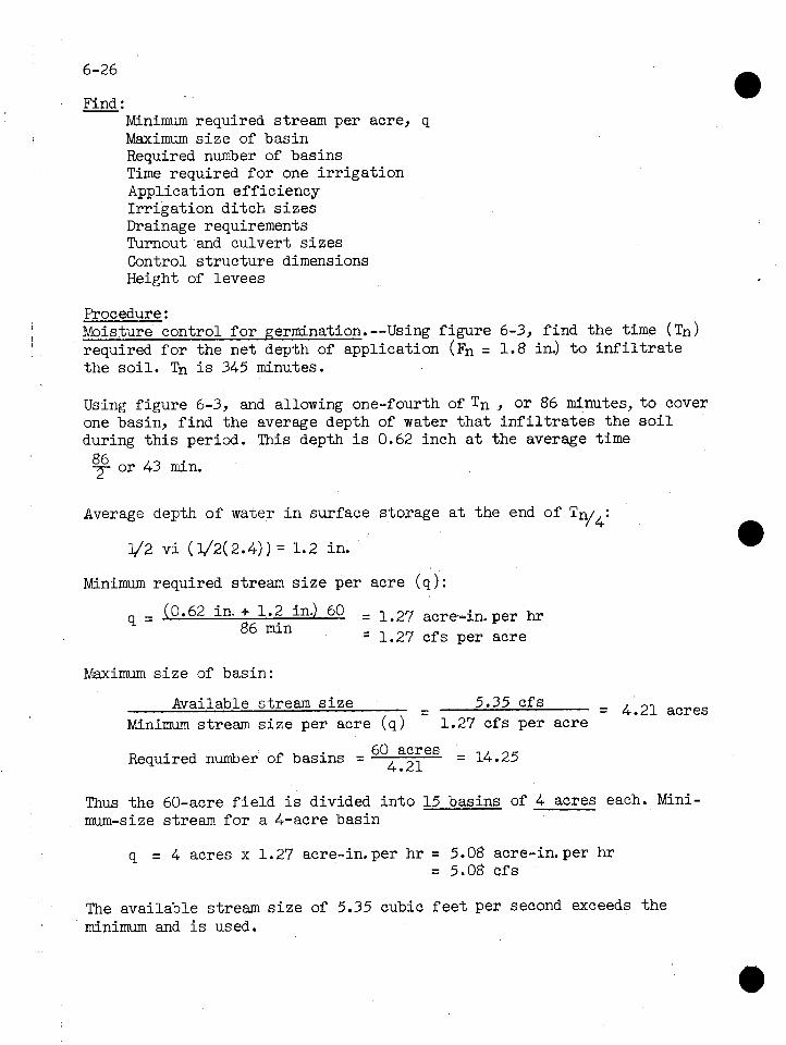
Find : - Wdnimum required stream per acre, q Maximum s i z e of basin Required number of basins Time required f o r one i r r i g a t i o n Application eff ic iency I r r i ga t i on d i t ch s i ze s Drainage requirements Turnout and culver t s i z e s Control s t r uc tu r e dimensions Height of levees
Procedure : Moisture control f o r germination.--Using f i gu re 6-3, f i nd t he time ( T ~ ) required f o r the ne t depth of application ( F ~ = 1.8 in.) t o i n f i l t r a t e t he s o i l . Tn i s 345 minutes.
Using f igure 6-3, and allowing one-fourth of T n , o r 86 minutes, to cover one basin, f i nd the average depth of water t h a t i n f i l t r a t e s the s o i l during t h i s period. This depth i s 0.62 inch a t the average time
86 7 or 43 min.
Average depth of water i n surface storage a t the end of Tn/4:
1/2 v i (1/2(2.4)) = 1.2 in.
Minimum required stream s i z e per acre ( q ) :
0.62 in. + 1.2 in.) 60 = 1-27 acre-in. per hr 9 = ( 86 min = 1.27 c f s per acre
Maximum s i z e of basin:
Available stream s i z e - - 5.35 c f s = 4.21 acres Minimum stream s i z e per acre (q ) 1.27 c f s per acre
Required number of basins = 60 acres = 14.25 4.21
Thus t he 60-acre f i e l d i s divided i n t o 15 basins of 4 acres each. Mini- mum-size stream f o r a 4-acre basin
q = 4 acres x 1.27 acre-in. per h r = 5.08 acre-in. per h r = 5.08 c f s
The available stream s i z e of 5.35 cubic f e e t per second exceeds t he minimum and i s used.
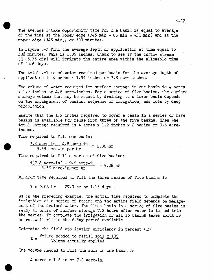
The average intake opportunity time f o r one basin is equal t o average of the time a t the lower edge (345 min + 86 min = 431 min) and a t the upper edge (345 min ), or 388 minutes.
In f igure 6-3 f ind the average depth of application a t time equal t o 388 minutes. This i s 1.95 inches. Check t o see i f the inflow stream (Q=5.35 c f s ) w i l l i r r i g a t e the e n t i r e area within the allowable time of f = 6 days.
The t o t a l volume of water required per basin f o r the average depth of application i s 4 acres x 1.95 inches or 7.8 acre-inches.
The volume of water required f o r surface storage i n one basin is 4 acres x 1.2 inches or 4.8 acre-inches. For a s e r i e s of f i v e basins, the surface storage volume t h a t may be reused by draining t o a lower basin depends on the arrahgement of basins, sequence of i r r iga t ion , and loss by deep percolation.
Assume t h a t the 1.2 inches required t o cover a basin i n a s e r i e s of f i v e basins is available f o r reuse from three of the f i v e basins. Then the t o t a l storage required is 4 acres x 1.2 inches x 2 basins or 9.6 acre- inches.
Time required t o f i l l one basin:
7.8 acre-in, + 4.8 acre-in. - 5.35 acre-in, per h r
- 2.36 hr
Time required t o f i l l a s e r i e s of f i v e basins:
5(7.8 acre-in.) + 9.6 acre-in. 5.35 acre-in. per hr = 9.08 hr
Minimum time required t o f i l l the three s e r i e s of f i v e basins i s
3 x 9.08 hr = 27.3 h r or 1.13 days ,
As i n the preceding example, the actual time required t o complete the i r r i ga t ion of a s e r i e s of basins and the e n t i r e f i e l d depends on manage- ment of the drained water. The f i r s t basin i n a serieg of f i v e basins is ready t o &rain of surface storage 7.2 hours a f t e r water is turned i n t o the se r ies . To complete the i r r i ga t ion of a l l 15 basins takes about 33 hours--well within the 6-day period available.
Determine the f i e l d application efficiency i n percent (E) :
E = Volume needed t o r e f i l l s o i l x 100
Volume actual ly applied
The volume needed t o f i l l t he s o i l i n one basin is
4 acres x 1.8 in. or 7.2 acre-in.
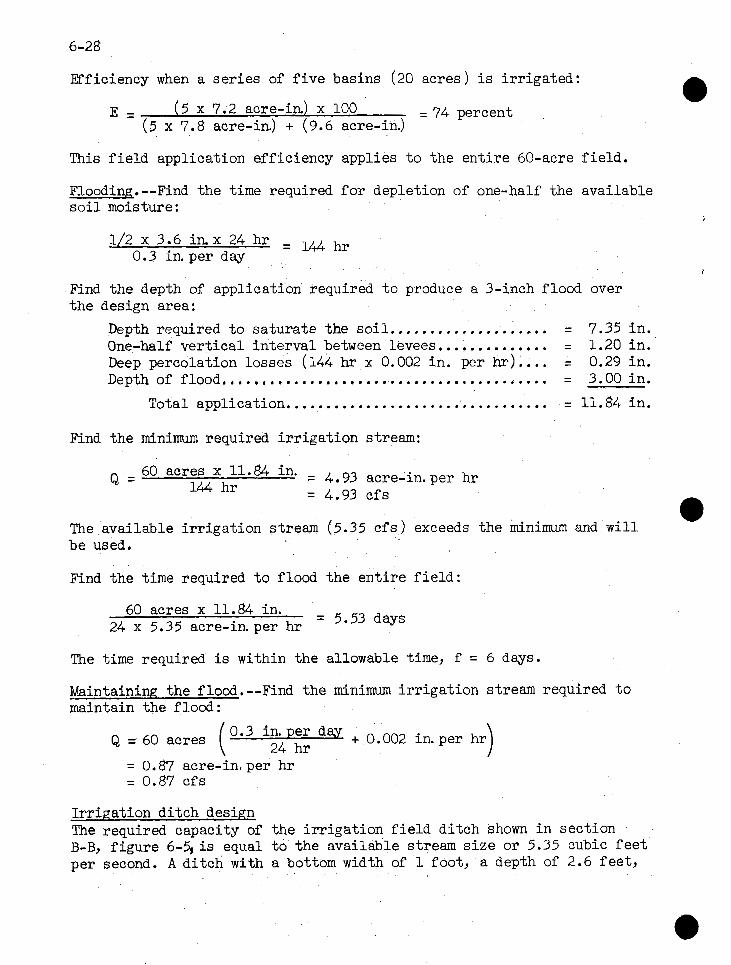
Efficiency when a ser ies of f i v e basins (20 acres ) i s i rr igated :
E = ( 5 x 7.2 acre-in) x 100 = 74 percent ( 5 x 7.8 acre-in,) + (9.6 acre-in.)
This f i e l d application efficiency applies t o the ent i re 60-acre f i e ld .
Flooding.--Find the time required fo r depletion of one-half the available s o i l moisture:
1/2 x 3.6 in. x 24 hr = 144 hr 0.3 in. per day
Find the depth of application required t o produce a 3-inch flood over the design area:
................. Depth required t o saturate the so i l . . , = 7.35 in . One-half ver t ica l interval between levees... . . . . . . . . . . . = 1.20 in. .... Deep percolation losses (144 hr x 0.002 in . per kr) = 0.29 in. Depth of flood.. . . . , . . . . . . . . . . . . . . . . . . . . . . , . . . . . . . . . . . , = 3.00 in.
................................. Total application = 11.84 in.
Find the minimum required i r r iga t ion stream:
Q = 60 acres 11*84 in' = 4, gj acre-in. per hr 144 hr = 4.93 cfs
The available i r r iga t ion stream (5.35 c f s ) exceeds the m i n i m and w i l l be used.
Find the time required t o flood the ent i re f i e ld :
60 acres x 11.84 in. = 5.53 days 24 x 5.35 acre-in. per hr
The time required is within the allowable time, f = 6 days.
Maintaining the flood.--Find the minimum i r r iga t ion stream required t o maintain the flood:
Q = 60 acres day + 0.002 in.per hr
= 0.87 acre-in. per hr = 0.87 cfs
Irr igat ion ditch design The required capacity of the i r r iga t ion f i e l d di tch shown in section B-B, f igure 6 - 5 i s equal t o the available stream s ize or 5.35 cubic f e e t per second. A ditch with a bottom width of 1 foot, a depth of 2.6 feet ,

s ide slopes of 1-1/2 t o 1, on a hydraulic gradient of 0.000125 foo t per foot, and having an "nu value of (3.045 has a capacity of 5.38 cubic f e e t per second, thus meeting t h i s requirement.
Drainwe requirements The drainage requirements, d i t ch s i ze s and capacit ies, a re the same as those shown i n sample calcula t ion 3.
Turnout and culver t s i z e , The required czpscity 9f t u r n m t s and zulvertc must be equal t o the
avai lable i r r i g a t i o n stream o r 5.35 cubic f e e t per second. Sizes a re
determined by the formula, Q = Ca &@ha
Try using a 21-inch concrete pipe, 10 f e e t long, with a square-cornered entrance operating under a head of 0.12 foot . The computation becomes:
Q = 0.80 x 2.405 t/2 x 32.2 x 0.12 = 5.35 c f s ( s a t i s f ac to ry )
In te r io r i r r i g a t i o n di tches and drainageways The required capacity of t h e combined i r r i g a t i c n di tches and drainage- ways shown i n sect ions C-C and D-D of f i gu re 6-5 mst be equal t o t h e avai lable i r r i r a t i o n stream or 5.35 cubic f e e t Der sdcond. ., Fi r s t , determine the s lope(s ) of t he hydraulic gradient i n t he ditches. This is t he i f fe rence between t he v e r t i c a l i n t e rva l ( v i ) between levees 9 and t he head (h ) required on the control s t ruc ture divided by t h e hori- zontal d is tance between levees ( I ) or,
v i - h - 0.2 f t - 0.12 f t S = -
1 264 f t = 0.0003C)3 ftl per f t
The design of the d i tch o r ditches i s :
Depth, d - - Bottom, b - Side slopes - - Area, A - - Hydraulic radius, r - - Roughness coeff ic ient , n = Slope, s - - Velocity, v - - Capacity, Q - -
2.1 f t 9, V-type 2 t o 1 8.82 sq f t 0.939 0.040 0.000303 f t per f t 0.621 cs 5.L.S cf s ( s a t i s f ac to ry )
Control s t ruc ture dimensions For r i c e and other close-growing crops, t he water l eve l i n each basin i s of ten controlled by a weir placed i n t he levee along t h e lower s i de of t he basin. These weir s t ruc tures are usual ly made of sheet metal o r some other su i t ab l e material and a re locate6 near an access road f o r conven- ience. They a re generally designed t o operate under a head of 0.2 t o 0.25 foot . When these s t ruc tures a r e used, t he operating head must be con- sidered i n determining t he height of the levees.

The weirs are made of sheet metal and are designed t o have a capacity equal t o the available stream capacity or 5.35 cubic f ee t per second, The formula fo r determining weir dimensions is :
With the value of C = 3.2, t ry cres t length L =14 f e e t and solve for t he operating head:
Height of levees
Vertical interval between levees.................. 0.20 f t .......................... Depth of flood ( 3 in . 1.. .25 f t Head on weir control structure.................... .24 f t ................................ Freeboard provided .30 f t Allowance fo r settlement.......................... .30 f t
Constructed height ........................... 1.29 f t say 1.3 f t
* U.S. GOVERNMENT PRINTING OFFICE : 196B 0-354-22B