section 02771 cure-in-place liner for sanitary sewer …
TRANSCRIPT

JMA/JW/ab/specs/02771 Tt #200-08466-17003 02771-1 062117
SECTION 02771
CURE-IN-PLACE LINER FOR SANITARY SEWER
PART 1 - GENERAL
1.01 REQUIREMENTS
A. The Work within this Section consists of the installation and testing of cured-in-place pipe(CIPP). The CIPP shall provide a structurally sound, joint-less and water-tight new pipewithin a pipe. The Contractor is responsible for proper, accurate and completeinstallation of the CIPP.
B. The finished liner shall extend over the installation length in a continuous, tight fitting,watertight pipe-within-a-pipe and shall be fabricated from materials which, wheninstalled, will be chemically resistant to withstand internal exposure to domestic sewage.
C. Neither the CIPP system, nor its installation, shall cause adverse effects to any of theOwner’s facilities or processes. The use of the product shall not result in the formationor production of any detrimental compounds or by-products at the treatment facilities.The Contractor shall test and monitor the levels of by-products produced as a result ofthe installation operations. The Contractor shall conduct installation operations andschedule cleanup in a manner to cause the least possible obstruction and inconvenienceto traffic, pedestrians, businesses, and property owners or tenants.
1.02 INSTALLER EXPERIENCE AND QUALIFICATIONS
A. The Contractor’s staff experience shall meet as a minimum the following requirements.The inability to document such experience may be grounds for rejecting the proposedinstaller’s staff.
1. The proposed Superintendent must have a minimum of three (3) years of CIPPlining supervisory field experience on projects totaling a minimum of 150,000 LFof 8-inch or greater CIPP liner installation using the methods and materialsproposed for this Work, as documented by verifiable references.Superintendent's resume of projects. Each reference project shall include thepipe dimensions, length of installation, size/type of flow control required toperform the Work, description of the actual work performed including installation method, owner's name, telephone number and contact person, date ofinstallation. It is required that the Superintendent(s) named are theSuperintendent(s) assigned to this project and on site during the entire length ofthe construction.
The Contractor is required to have at least 1 qualified Superintendent on site atall times during the construction activities. All referenced experience shall be forprojects completed within the United States or Canada and shall have used the

JMA/JW/ab/specs/02771 Tt #200-08466-17003 02771-2 062117
same installation method, CIPP liner and resin combination proposed for this project. References will be checked.
2. The proposed Superintendent for the segmental lining crew must have a minimum of three (3) years of CIPP segmental lining supervisory field experience on projects totaling a minimum of 500 8-inch or greater CIPP segmental liner installations using the methods and materials proposed for this Work, as documented by verifiable references. Superintendent's resume of projects. Each reference project shall include the pipe dimensions, length of installation, size/type of flow control required to perform the Work, description of the actual work performed including installation method, owner's name, telephone number and contact person, date of installation. It is required that the Superintendent(s) named are the Superintendent(s) assigned to this project and on site during the entire length of the construction. Installation Crew: At least 1 person other than the Superintendent from the CIPP installation crew shall have a minimum of 1-year of CIPP experience totaling at least 20,000 lineal feet of 8-inch or greater installed liner. The crewmember with listed qualifications must be on the project site during all installation activities and for the entire duration of the contract.
3. Boiler Technician: Contractor shall provide the name and information for the boiler technician who will perform the actual Work. The boiler technician must have a minimum of 2 projects totaling at least 10,000 lineal feet of CIPP lining in which a similar position was held.
4. Lateral Cutter Technician: Contractor shall provide the name and information for the technician who will perform the actual Work. The lateral cutter technician must have a minimum of 5 projects totaling at least 20,000 lineal feet of CIPP lining in which a similar position was held.
5. Lead CCTV inspector shall be NASSCO PACP certified to report liner defects.
6. The final decision to accept or reject the product, manufacturer, and/or installer lies solely with the Owner. The named Manufacturer, Field Superintendent, CIPP Lead Installer, Boiler Technician, and Lateral Cutter must be employed to perform the Work for the entire duration of the contract, unless changes are specifically authorized by the Owner.
1.03 PERFORMANCE WORK STATEMENT
A. The Contractor shall submit, before any lining WORK is performed, to the Owner a Performance Work Statement (PWS) which clearly defines the CIPP product delivery in conformance with the requirements of these contract documents. The PWS shall contain at a minimum the following:
1. Contractor’s certificate of compliance that clearly indicates that the CIPP will conform to the project requirements as outlined in Specification Section 01010 Summary of Work and as delineated in these specifications.

JMA/JW/ab/specs/02771 Tt #200-08466-17003 02771-3 062117
2. A detailed installation plan describing:
a. All preparation work (cleaning operations, pre-CCTV inspections, by-pass pumping, and traffic control)
b. Installation procedure and method of curing c. Service reconnection d. Quality control and testing to be performed e. Post-CCTV inspection f. Warrantees g. Description of the proposed CIPP lining technology.
3. A detailed plan for identifying all active service connections prior to, and in advance of, mainline installation. The Contractor will assume all costs associated with improper or inadequate verifications of active service or lateral connections. No compensation will be paid for remedying reinstatement of inactive laterals or for time delays due to improper or inadequate active service verifications.
4. The qualifications of the Contractor.
a. Name, business address and telephone number
b. Personnel names, experience, and certifications for Field Superintendent, CIPP lead Installer, Lateral Cutter, Boiler Technician, and Lead CCTV NASSCO PACP Certificated Inspector to be directly involved with this project. The Contractor shall sign and date the information provided and “certify that to the extent of his knowledge, the information is true and accurate, and that the supervisory personnel will be directly involved with and used on this project”. Substitutions of personnel and/or methods will not be allowed without written authorization of the Owner.
c. Specialty technicians shall be certified by the equipment manufacturer
and/or its authorized representative. Certifications shall be submitted to the Owner/Professional.
5. Proposed manufacturer’s technology data shall be submitted for all CIPP products and all associated technologies to be furnished.
6. All tools and equipment required for a complete installation of the CIPP.
a. Clearly describe all equipment including proposed back-up equipment to be furnished for this project.
b. Identify redundant tools and equipment to be kept on the job site in the event of equipment breakdown.

JMA/JW/ab/specs/02771 Tt #200-08466-17003 02771-4 062117
c. The Contractor shall outline the mitigation procedure to be implemented in the event of key equipment failure during the installation process for the CIPP.
7. A detailed description of the Contractor’s proposed procedures for the removal of any existing blockages in the pipeline that may be encountered during the cleaning process.
8. Detailed public notification plan for stage notification to residences affected by the CIPP installation.
9. An odor control plan that will ensure that project specific odors will be minimized at the project site and surrounding area.
10. Outline specific repair or replacement procedures for potential defects that may occur in the installed CIPP. Repair or replacement procedures shall be as recommended by the CIPP system manufacturer and shall be submitted prior to any Work.
a. Repairable defects that may occur in the installed CIPP shall be specifically defined by the Contractor based on the manufacturer’s recommendations, including a detailed step-by-step repair procedure, resulting in a finished product meeting the requirements of the specifications.
b. Un-repairable defects that may occur to the CIPP shall be clearly defined by the Contractor based on the manufacturer’s recommendations, including a recommended procedure for the removal and replacement of the CIPP.
1.04 REFERENCES
A. Codes, Specifications, and Standards
1. Codes, specifications, and standards referred to by number or title shall form a part of this specification to the extent required by the references thereto. Latest revisions shall apply, unless otherwise shown or specified.
2. All American Society for Testing and Materials (ASTM) Standards noted below shall be to the latest revised version.
D543 – Standard and Practice for Evaluating the Resistance of Plastics to Chemical Reagents
D638 – Standard Test Method for Tensile Properties of Plastics
D790 – Standard Test Methods for Flexural Properties of Un-reinforced and Reinforced Plastics and Electrical Insulating Materials

JMA/JW/ab/specs/02771 Tt #200-08466-17003 02771-5 062117
D792 – Standard Test Methods for Density and Specific Gravity of Plastics by Displacement
D2122 – Standard Test Method for Determining Dimensions of Thermoplastic Pipe and Fittings
D2837 – Obtaining Hydrostatic Design Basis for Thermoplastic Pipe Materials
D2990 – Standard Test Methods for Tensile, Compressive, and Flexural Creep and Creep-Rupture of Plastics
D3567 – Standard Practice for Determining Dimensions of Fiberglass (Glass-Fiber-Reinforced Thermosetting Resin) Pipe and Fittings
D3681 – Standard Test Method for Chemical Resistance of “Fiberglass (Glass Fiber Reinforced Thermosetting Resin) Pipe and Fittings
D5813 – Standard Specification for Cured-in Place Thermosetting Resin Sewer Pipe
F1216 – Standard Practice for Rehabilitation of Existing Pipelines and Conduits by Inversion and Curing of a Resin-impregnated Tube
F1743 – Standard Practice for Rehabilitation of existing pipelines and conduits by pulled-in-place installation of cured-in-place thermo setting resin pipe
F2019 - Standard Practice for Rehabilitation of Existing Pipelines and Conduits by the Pulled in Place Installation of Glass Reinforced Plastic (GRP) Cured-in-Place Thermosetting Resin Pipe (CIPP)
F2561 - Standard Practice for Rehabilitation of a Sewer Service lateral and Its Connection to the Main Using a One Piece Main and Lateral Cured-in-Place Liner
F2599 – The Sectional Repair of Damaged Pipe By Means of An Inverted Cured-In-Place Liner.
1.05 PRE-TREATMENT OF REGULATED CHEMICALS TO DISCHARGE INTO SEWER
A. CIPP liner systems using resins containing styrene or other regulated chemicals that will be discharged into the wastewater system shall be required to reduce the concentration of Styrene in the cure water prior to discharge to the sanitary sewer. The discharge limits are as follows:

JJMA/W/ab/specs/02771 Tt #200-08466-17003 02771-6 062117
Discharge Limits to Wastewater Treatment Plant
Total Gallons of Discharge Including
Water Added for cool down
Maximum Styrene Concentration Limit for
Discharge
(PPM)
Maximum Total Pounds per Day of Styrene to be Discharged
(ppd)
< 500,000 < 250,000 < 100,000
1. A single day’s or line segment water discharge in excess of 500,000 gallons per day shall require approval by the Owner’s Environmental Compliance Section for separate concentration limit evaluation and approval.”
B. CIPP liner systems using resins containing styrene or other regulated chemicals that will be discharged into the wastewater system shall require a pre-treatment plan to remove the regulated chemicals to acceptable levels prior to discharge. The Contractor shall submit the pre-treatment plan to the Owner for approval prior to discharge. The information required shall include:
1. MSDS for all chemicals used in the process and that will be discharged into the wastewater system.
2. Representative analytical data that was performed in the past for the proposed process, as collected from the wastewater stream.
3. The addresses and mapped locations of the discharge.
4. The total duration of discharge request.
5. The anticipated discharge temperature. Discharges in excess of 140°F are not permitted.
6. The Contractor shall submit for approval a summary table of pre-treatment design calculations in Excel containing the following information:
a. Dates of discharge of each section
b. Lining section numbers using the OCUD numbering system
c. Length and diameter of each section
d. Volume (in gallons) of inversion water of each section
e. Volume (in gallons) of cool down water of each section
f. Total volume (in gallons) of inversion and cooling water of each section

JMA/JW/ab/specs/02771 Tt #200-08466-17003 02771-7 062117
g. Regulated chemical (in pounds) in discharge volume of each section
h. Reduction chemical (in pounds) to meet post-treatment concentration limit
i. Reaction time period (in hours) to achieve post-treatment concentration limit
j. Cool down time period (in hours)
k. Regulated chemical post-treatment concentration limit (in PPM)
7. The Contractor shall provide pre-treatment and post-treatment sampling and laboratory analysis of the process wastewater and submit the results to the Owner for verification.
C. After curing, the Contractor shall obtain a post-treatment cure water sample at each site and submit for laboratory analysis.
1. The following laboratory analysis is required:
a. One (1) sample to be collected from the treated water line segment and analyzed for “Styrene” using EPA Method 8260.
b. One (1) “Trip Blank” sample, analyzed for “Styrene” using EPA Method 8260.
2. The Contractor shall submit the analytical report to the Owner for approval.
3. The Contractor shall be responsible for all costs related to laboratory analytical testing of the water samples collected.
4. Sampling shall continue for each successive lining segment until the laboratory results verify the Contractor’s competency in determining the amount of styrene reduction tablets/material required for a given water volume. Competency will be determined by meeting the stated discharge limits.
5. Once the sample results demonstrate that the discharge limits have been met the Contractor shall follow similar styrene reduction procedures for subsequent lining segments, but sampling will not be required.
6. Should samples from three locations not meet the discharge limits, the Owner may require the Contractor to hold cure water in place until laboratory results confirm the water is below the discharge limits.
7. The Owner reserves the right to obtain samples at any site on any line segment to ensure compliance with the discharge limits.”
JMA/JW/ab/specs/02771 Tt #200-08466-17003 02771-8 062117
1.06 RESPONSIBILITY FOR OVERFLOWS AND SPILLS
A. It shall be the responsibility of the Contractor to schedule and perform his work so as to result in no overflows or spills of sewage or combined sewage from the system. If sewage flows are such that they interfere with the Contractor's ability to perform work, the Contractor shall be responsible for scheduling his work during low flow periods or provide bypass pumping.
B. In the event of overflows caused by the Contractor's work activities, the Contractor shall immediately take appropriate action to contain and stop the overflow, clean up the spillage, disinfect the area affected by the spill, and notify the Owner and all necessary regulatory agencies in a timely manner.
C. Contractor will indemnify and hold harmless the Owner for any fines or third-party claims for personal or property damage arising out of a spill or overflow that is fully or partially the responsibility of the Contractor. Should fines subsequently be imposed as a result of any overflow for which the Contractor is fully or partially responsible, the Contractor shall pay all such regulatory and other fines and all of the Owner's legal, engineering, and administrative costs in defending such fines and claims associated with the overflow.
D. If the Contractor is required to hold cure water due to unacceptable styrene testing results, the Contractor shall be required to provide bypass pumping or other means to insure wastewater service is not disrupted during the hold period.
1.07 SHOP DRAWINGS AND SUBMITTALS
A. Submittals shall be submitted to the Owner for review and acceptance prior to construction in accordance with the General Conditions and specifications Section 01340. Submittals shall include the following:
1. Performance Work Statement shall be provided with a table of contents and tabbed sections.
2. Product:
a. A list of projects from the Manufacturer that total a minimum of 500,000 linear feet of liner installed in the United States. An Excel spread sheet shall be included listing as a minimum the name of projects, diameters of mains, linear footage of mains, completion date, contract amount, name of owner, address, contact person, and phone number.
b. Fabric tube – manufacturer and description of product components.
c. Flexible membrane (coating) material and recommended repair (patching) procedure if applicable.
d. Raw resin data – manufacturer and description of product components for all resin types.

JMA/JW/ab/specs/02771 Tt #200-08466-17003 02771-9 062117
e. Manufacturer’s shipping, storage and handling recommendations for all
components of the CIPP system.
f. All MSDS sheets for all materials to be furnished.
g. Tube wet-out and cure method including:
1) A complete description of the proposed wet-out procedure for the proposed technology
2) The manufacturer’s recommended cure method for each diameter and thickness of CIPP liner to be installed including the curing medium and the method of application
3. Quality Control Plan
a. Defined responsibilities of the Contractor’s personnel for assuring that all quality requirements are met. These will be assigned by the Contractor to specific personnel.
b. Proposed procedures for quality control, product sampling and testing shall be defined and submitted as part of the Plan.
c. Proposed methods for product performance controls, including the method of and frequency of product sampling and testing both in raw material form and cured product form.
d. Inspection forms and guidelines for quality control inspections shall be
prepared in accordance with the standards specified within this specification.
e. The manufacturer shall furnish a check list containing key elements of the CIPP installation criteria that is important for the Owner to ensure that quality control and testing requirements are performed in accordance with these specifications.
4. Engineering design calculations shall be submitted in a timely fashion prior to construction, in accordance with the Appendix of ASTM F-1216, for each length of liner to be installed including the thickness of each proposed CIPP. It will not be acceptable for the Contractor to submit a design for the most severe line condition and apply that design to all of the line sections.
All calculations shall include data that conforms to the requirements of these specifications.

JMA/JW/ab/specs/02771 Tt #200-08466-17003 02771-10 062117
a. These calculations shall be performed and certified by a Professional Engineer registered in the State of Florida.
b. The manufacturer shall certify as to the compliance of its materials to the values used in the calculations.
5. The liner manufacturer shall submit a tabulation of time versus temperature. This tabulation shall show the lengths of time that exposed portions of the liner will endure without self-initiated cure or other deterioration beginning. This tabulation shall be at 5°F (degrees Fahrenheit) increments ranging from 70°F to 100°F.
The manufacturer shall also submit his analysis of the progressive effects of such "pre-cure" on the insertion and cured properties of the liner.
6. Certified copies of test reports of factory tests required by the applicable standards and this Section.
7. Manufacturer's installation instructions and procedures.
8. CIPP Installation Record (Shot Record) to include shot number and corresponding manhole to manhole pipe reaches for each scheduled installation, design thickness, actual thickness delivered to the site, pipe diameter, reach length, total length of shot, and number of laterals.
9. Wastewater pre-treatment plan including data, measurements, assumptions, calculations and procedures for the pre-treatment of CIPP process wastewater containing regulated chemicals.
10. Manufacturer's detailed procedures for repairing liners that have been installed incorrectly or that have failed during installation.
11. Contractor's procedures and materials for service renewal including time and duration of sewer service unavailability and a complete description of the methods he intends to use to reconnect the existing laterals.
12. Sampling procedures and locations for obtaining representative samples of the finished liner.
13. Sampling tests for compliance by an independent laboratory shall be made according to the applicable ASTM specification and the manufacturer's quality control program.
B. A final certificate of compliance with this specification shall be provided by the manufacturer for all lining material furnished.
1.08 WARRANTY
A. The materials used for the project shall be certified by the manufacturer for the specified purpose. The Contractor shall warrant the liner material and installation for a period of one (1) year. During the Contractor warranty period, any defect which may materially

JMA/JW/ab/specs/02771 Tt #200-08466-17003 02771-11 062117
affect the integrity, strength, function and/or operation of the pipe, shall be repaired at the Contractor’s expense in accordance with procedures in these specifications and as recommended by the manufacturer.
B. The Contractor shall conduct a warranty television inspection via use of CCTV within 11 months following completion of the project. If it is found that any of the CIPP has developed abnormalities since the completion of the project, the abnormalities shall be repaired and/or replaced by the Contractor promptly as per these specifications and as recommended by the manufacturer.
C. On any work completed by the Contractor that is defective and/or has been repaired, the Contractor shall warrant this work for an additional one (1) year.
1.09 DELIVERY, STORAGE, AND HANDLING
A. The Contractor shall be responsible for the delivery, storage, and handling of products. No products shall be shipped to the job site without the approval of the Owner.
B. Keep products safe from damage. Promptly remove damaged products from the job site. Replace damaged products with undamaged products.
C. The wet-out facility shall write the Shot number, total wet-out length, thickness, pipe width, and resin type on each bag delivered to the project.
1.10 CONNECTING PIPE DETAILS
A. Each pipe entering and exiting the manhole shall be photographed where possible and inspected to determine diameter, pipe material, debris levels, and rim to invert distance (to 0.1-feet).
PART 2 - PRODUCTS
2.01 GENERAL
A. The materials used shall be designed, manufactured, and intended for sanitary sewer pipe relining and the specific application in which they are used. The materials shall have a proven history of performance in sewer relining and rehabilitation.
B. Pipe lining products pre-approved by the Owner include: Insituform Technologies (CIPP Liner), National Liner (CIPP Liner), LMK Enterprises (Performance Liner), Stevens Technologies (CIPP Liner 2 part 100% epoxy), Inner Cure Technologies (Reichold/Dion CIPP Liner), Lanzo Lining Services (Lanzo CIPP Lining System), and Premier Pipe (Premier Pipe CIPP Lining System), Layne Inliner (CIPP Liner), and Miller Pipeline (CIPP Liner). All products must meet the specification herein and will require approval prior to installation.
C. All materials, shipped to the project site, shall be accompanied by test reports certifying that the material conforms to the ASTM listed herein. Materials shall be shipped, stored, and handled in a manner consistent with written recommendations of the CIPP system

JMA/JW/ab/specs/02771 Tt #200-08466-17003 02771-12 062117
manufacturer to avoid damage. Damage includes, but is not limited to, gouging, abrasion, flattening, cutting, puncturing, or ultra-violet (UV) degradation. On site storage locations, shall be approved by the Owner. All damaged materials shall be promptly removed from the project site at the Contractor’s expense and disposed of in accordance with all current applicable agency regulations.
D. The finished pipe liner in place shall be fabricated from materials which when complete are chemically resistant to and will withstand internal exposure to domestic sewage having a pH range of 5 to 11 and temperatures up to 150ºF.
E. Take all necessary field measurements of the existing pipe (including diameter, ovality and length) prior to manufacturing liners.
F. The minimum length shall be that deemed necessary by the Contractor to effectively span the distance from the inlet to the outlet of the respective manholes unless otherwise specified. The Contractor shall verify the lengths in the field before manufacturing.
2.02 STRUCTURAL REQUIREMENTS
A. Each CIPP shall be designed to withstand internal and/or external loads as dictated by the site and pipe conditions. The CIPP design shall assume no bonding to the original pipe wall.
B. The Contractor must have performed long-term testing for flexural creep of the CIPP pipe material installed by his company. Such testing results are to be used to determine the long-term, time dependent flexural modulus to be utilized in the product design. The long-term modulus shall not exceed 50 percent of the short-term value for the resin system and shall be verifiable through testing. The materials utilized for the contracted project shall be of a quality equal to or better than the materials used in the long-term test with respect to the initial flexural modulus used in the CIPP design.
C. The Contractor shall submit, prior to installation of the lining materials, certification of the compliance with these specifications and/or the requirements of the CIPP system. Certified material test results shall be included that confirm that all materials conform to these specifications. Materials not complying with these requirements will be rejected.
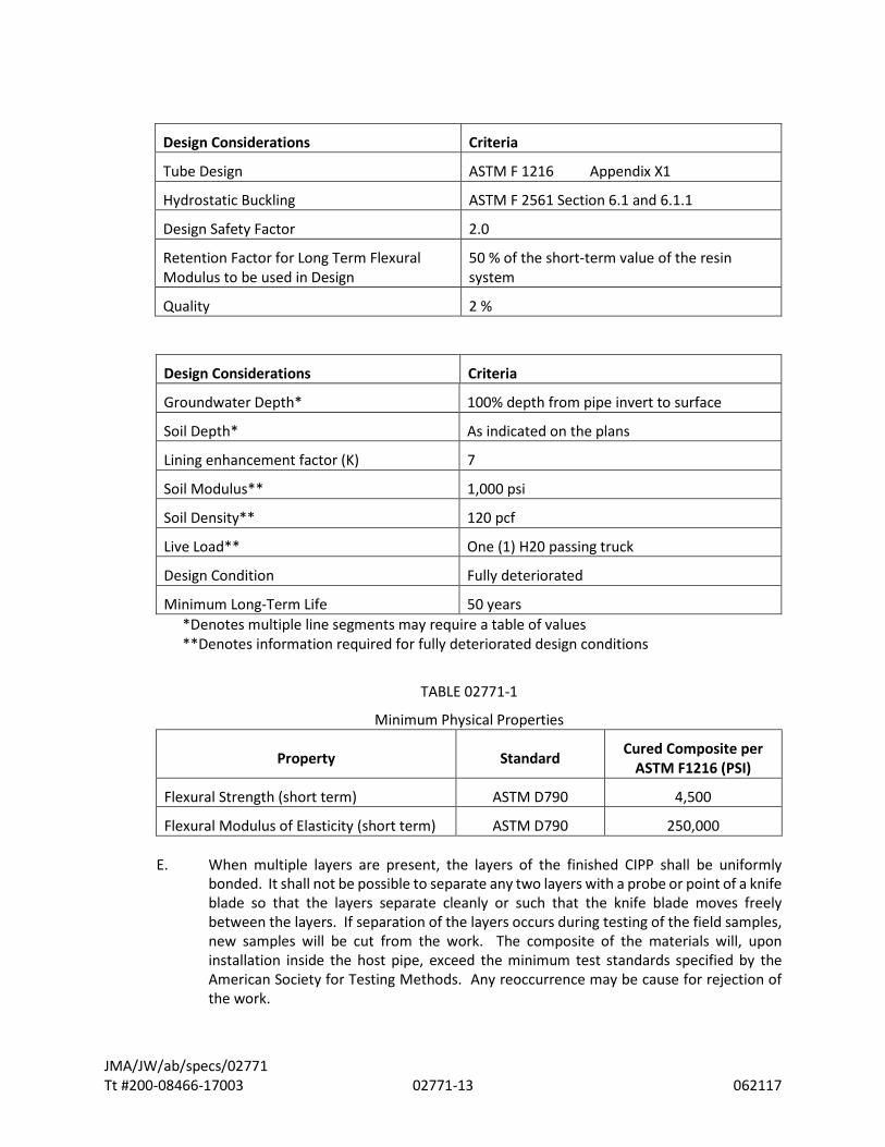
D. The design thickness of the CIPP shall be arrived at using standard engineering methodology as found in ASTM F1216 and the physical properties. In no case shall the finished thickness of the cured liner be less than 4.5 millimeters. The required cured structural CIPP wall thickness shall be based, as a minimum, on the physical properties described in TABLE 02771 - 1 Minimum Physical Properties and per the design of the Professional Engineer and in accordance with the design equations in ASTM F 1216 Appendix X1 and the following design parameters:
JMA/JW/ab/specs/02771 Tt #200-08466-17003 02771-13 062117
Design Considerations Criteria
Tube Design ASTM F 1216 Appendix X1
Hydrostatic Buckling ASTM F 2561 Section 6.1 and 6.1.1
Design Safety Factor 2.0
Retention Factor for Long Term Flexural Modulus to be used in Design
50 % of the short-term value of the resin system
Quality 2 %
Design Considerations Criteria
Groundwater Depth* 100% depth from pipe invert to surface
Soil Depth* As indicated on the plans
Lining enhancement factor (K) 7
Soil Modulus** 1,000 psi
Soil Density** 120 pcf
Live Load** One (1) H20 passing truck
Design Condition Fully deteriorated
Minimum Long-Term Life 50 years *Denotes multiple line segments may require a table of values **Denotes information required for fully deteriorated design conditions
TABLE 02771-1
Minimum Physical Properties
Property Standard Cured Composite per ASTM F1216 (PSI)
Flexural Strength (short term) ASTM D790 4,500
Flexural Modulus of Elasticity (short term) ASTM D790 250,000
E. When multiple layers are present, the layers of the finished CIPP shall be uniformly bonded. It shall not be possible to separate any two layers with a probe or point of a knife blade so that the layers separate cleanly or such that the knife blade moves freely between the layers. If separation of the layers occurs during testing of the field samples, new samples will be cut from the work. The composite of the materials will, upon installation inside the host pipe, exceed the minimum test standards specified by the American Society for Testing Methods. Any reoccurrence may be cause for rejection of the work.

JMA/JW/ab/specs/02771 Tt #200-08466-17003 02771-14 062117
2.03 CURED-IN-PLACE LINER
A. Fabric
1. The Contractor shall determine the minimum tube length necessary to effectively span the designated run between manholes. The Contractor shall verify the lengths in the field prior to ordering and prior to impregnation of the tube with resin, to ensure that the tube will have sufficient length to extend the entire length of the run. The Contractor shall also measure the inside diameter of the existing pipelines in the field prior to ordering liner so that the liner can be installed in a tight-fitted condition.
2. The sewn tube shall consist of one or more layers of absorbent non-woven felt fabric and meet the requirements of ASTM F-1216, ASTM F1743, or ASTM D5813. The tube shall be constructed to withstand installation pressures, have sufficient strength to bridge missing pipe, and stretch to fit irregular pipe sections.
3. The wet out tube shall have a relatively uniform thickness that when compressed at installation pressures will equal or exceed the calculated minimum design CIPP wall thickness.
4. The flexible tube shall be fabricated to a size that when installed will neatly fit (minimum 99.75%) the internal circumference of the existing sanitary sewer lines (including services). Allowance shall be made for circumferential stretching during insertion so that the final cured product is snug against the wall of the host pipe.
5. The outside layer of the tube shall be coated with an impermeable, flexible membrane that will contain the resin and allow the resin impregnation (wet out) procedure to be monitored.
6. The tube shall contain no intermediate or encapsulated elastomeric layers. No material shall be included in the tube that may cause delamination in the cured CIPP. No dry or unsaturated layers shall be evident.
7. The wall color of the interior pipe surface of CIPP after installation shall be a relatively light reflective color so that a clear detailed examination with closed circuit television inspection equipment may be made.
8. Seams in the tube shall be stronger than the non-seamed felt material.
9. The tube shall be marked for a distance at regular intervals along its entire length, not to exceed five feet. Such markings shall include the Manufacturers name or identifying symbol.
10. Unless otherwise specified, the Contractor will use a polyester filter felt tube and a resin and catalyst system compatible with the inversion process and having the minimum physical properties for the cured pipe identified in Table 02771 - 1 Minimum Physical Properties.
JMA/JW/ab/specs/02771 Tt #200-08466-17003 02771-15 062117
B. Resin
1. The Contractor shall provide a submittal per Section 01340 of the specifications for the type of resin to be used for each pipe material prior to commencement of construction.
2. The resin system shall be a corrosion resistant polyester or vinyl ester resin and catalyst system or epoxy and hardener system that when properly cured within the tube composite, meets the minimum requirements of ASTM F1216, ASTM F1743 or F2019, the physical properties given herein these specifications Section 02771 and those, which are to be utilized in the design of the CIPP for this project.
3. The resin used shall not contain non-strength enhancing fillers.
4. The Contractor shall submit the resin characteristics, including filler identification, to the Owner for approval prior to lining activities.
5. The resin shall produce a CIPP that will comply with the structural and chemical resistance requirements of the specification.
6. The Contractor is responsible for ensuring that the appropriate resin is used for optimal adherence to the existing pipe materials and note what CIP materials will be used for lining through each type of material in their submittals and how this will be tracked prior to installation.
PART 3 - EXECUTION
3.01 PREPARATION
A. Prior to any lining of a pipe so designated:
1. It shall be the responsibility of the Contractor to remove all internal debris and clean the existing sewer line and/or lateral in accordance with the recommendations of the liner manufacturer prior to installation of the liner and in accordance with Section 02761 "Cleaning Sanitary Sewer Systems." Both mainline and lateral line shall be cleaned.
a. Preparation of the interior surface shall be accomplished by a thorough high-pressure water-jet cleaning. The pipe shall be left free of all loose sand, rock, or other deleterious materials. Any roots in the pipe shall be either removed or cut off flush with the interior.
b. If conditions such as broken pipe and major blockages are found that will prevent proper cleaning or where additional damage would result if cleaning is attempted or continued, the Contractor shall notify the Owner immediately. The Owner will determine what course of action will be taken to complete the project.
JMA/JW/ab/specs/02771 Tt #200-08466-17003 02771-16 062117
c. Precautions shall be taken by the Contractor to ensure that no damage or flooding of public or private property is caused by the cleaning operation.
d. The Owner shall inspect the prepared pipe for cleanliness and
smoothness before the Contractor is authorized to proceed with pipe lining operations.
2. Certified PACP personnel trained in locating breaks, obstacles and service connections by closed circuit television shall perform inspection of existing sewer lines. The interior of the line shall be carefully inspected in accordance with Section 02762 "Televising Sanitary Sewer Systems" to determine the location of laterals in any condition that may prevent proper installation of the liner pipe into the lines. Such conditions shall be noted so they can be corrected. A digital data video and a suitable log shall be prepared by the Contractor during the Work and provided to the Owner a minimum of two weeks prior to liner installation.
3. The Contractor shall provide for the flow of sewage around the section or sections of pipe designated for lining as specified in Section 02516 "Collection System Bypass."
a. Flow control shall be exercised as required to ensure that no flowing sewage comes into contact with sections of the sewer under repair.
b. A sewer line plug shall be inserted into the sewer upstream from the section to be repaired. The plug shall be so designed that all or any portion of the sewage flows can be released.
During the review, testing and installation portion of the operation, flows shall be shut off in order to properly install the cured-in-place pipe lining. The upstream manholes shall be constantly monitored for degree of surcharging. After the installation is complete, flows shall be restored to normal level.
c. Wherever lines are blocked off and the possibility of backing up the
sewage and causing harm to public and private property is foreseen, it shall be the Contractor's responsibility to bypass flow from manhole to manhole.
d. Bypassing shall be accomplished using sewer plugs with pump connections, by pumping down surcharged manholes, or by other methods acceptable to the Owner. All bypassed flow must be discharged to a sanitary sewer. Bypassed flow shall not be allowed to enter any storm line, drainage ditch or street gutter.
e. During a bypass operation, the pump shall be manned continuously; the
Contractor shall maintain the pump and bypass equipment; and shall be responsible for any damages to public or private property due to the malfunction of same.
JMA/JW/ab/specs/02771 Tt #200-08466-17003 02771-17 062117
4. The Contractor shall clear the line of obstructions such as solids, dropped joints, protruding service connections or collapsed pipe that will prevent the insertion of the liner pipe. If inspection reveals an obstruction that cannot be removed by conventional sewer cleaning equipment, then the Owner shall be notified immediately.
5. Do not install liner if ground water temperatures and/or ambient temperatures are excessive or do not meet the manufacturer’s recommendations for the product installation procedures.
6. Notification of Public or Customers: Customers shall be notified by the Contractor with door hangers at least 3 days prior to the shutdown of any lateral services. The door hanger shall be approved by the Owner and advise the customers of when the Work will begin, expected date of completion, the type of work, and contact person for any questions on the door hanger.
When it is necessary to shut down a private sewer lateral while work is in progress and before the laterals are reconnected, the customers shall be notified by the Contractor. No sewer or water service is to remain shut down for more than a period of 8-hours unless the Contractor provides substitute services for the residents. The Contractor will assume all costs associated with improper or inadequate verifications of active service or lateral connections. No compensation will be paid for remedying reinstatement of inactive laterals or for time delays due to improper or inadequate active service verifications.
Commercial sewer services shall be maintained at all times that the business is open. No sewage from the services or main line shall be discharged on the ground or in waterways.
7. Contractor shall coordinate pump stations, force main and sanitary sewer operation, bypass and shutdown control with the Owner.
8. Traffic Control: The Contractor shall provide all traffic control measures required for the safety of the public, workers and equipment during the Work and in accordance with FDOT, the City or County, and the Owner.
9. The Contractor shall provide critical backup equipment to insure that the lining operation progresses without interruption. Required backup equipment shall include at a minimum 1 additional lateral cutter system and 1 additional CCTV camera system.
3.02 INSTALLATION OF LINER
A. The CIPP liner shall be installed and cured in the host pipe per the manufacturer’s specifications as described and submitted in the Performance Work Statement. CIPP installation shall be in accordance with the applicable ASTM Standards with the following modification:
1. Prior to installation and as recommended by the manufacturer remote temperature gauges or sensors shall be placed inside the host pipe to monitor the temperatures during the cure cycle. Liner and/or host pipe interface temperature shall be monitored and logged during curing of the liner.

JMA/JW/ab/specs/02771 Tt #200-08466-17003 02771-18 062117
2. The heat source shall be fitted with suitable monitors to gauge the temperature of the incoming and outgoing heat source. Another such gauge shall be placed between the impregnated reconstruction tube and the pipe invert at the remote manhole to determine the temperatures during cure. The resin manufacturer shall recommend temperature in the line during the cure period.
3. The wet-out tube shall be positioned in the pipeline using the method specified by the manufacturer. Care should be exercised not to damage the tube as a result of installation. The tube shall be inverted through an existing manhole or approved access point and fully extend to the next designated manhole or termination point. Sufficient excess resin will be provided to insure excretion into cracked pipe and/or joints of the host pipe after curing.
4. After inversion is completed, the Contractor shall supply suitable heat source and recirculation equipment. The equipment shall be capable of delivering the heat source throughout the section uniformly to raise the temperature above the temperature required to affect a cure of the resin. This temperature shall be determined by the resin/catalyst system employed.
Temperatures shall be monitored and recorded throughout the installation process to ensure that each phase of the process is achieved at the manufacturer's recommended temperature levels. Copies of these records shall be given to the Owner at the completion of each installation.
5. Curing shall be accomplished by utilizing the appropriate medium in accordance with the manufacturer’s recommended cure schedule. The curing source input and output temperatures shall be monitored and logged during the cure cycles if applicable. The manufacturer’s recommended cure method and schedule shall be used for each line segment installed, and the liner wall thickness and the existing ground conditions with regard to temperature, moisture level, and thermal conductivity of soil, per ASTM Standards as applicable, shall be taken into account by the Contractor.
6. For heat cured liners, if any temperature sensor or multiple sensors do not reach the temperature as specified by the manufacturer to achieve proper curing or cooling, the installer can make necessary adjustments to comply with the manufacturer’s recommendations. The system computer should have an output report that specifically identifies each installed sensor station in the length of pipe, indicates the maximum temperature achieved and the sustained temperature time. Each sensor should record both the maximum temperature and the minimum cool down temperature and comply with manufacturer’s recommendations.
7. For UV cured liners, all light train sensor readings, recorded by the tamper proof computer, shall provide output documenting the cure along the entire length of the installed liner. The cure procedure shall be in accordance with the manufacturer’s recommendation as included in the performance work statement.
8. Temperatures and curing data shall be monitored and recorded by the Contractor throughout the installation process to ensure that each phase of the process is achieved as approved in accordance with the CIPP system manufacturer’s recommendations.

JMA/JW/ab/specs/02771 Tt #200-08466-17003 02771-19 062117
9. The Contractor shall immediately notify the Owner of any delays taking place during the insertion operation. Such delays shall possibly require sampling and testing by an independent laboratory of portions of the cured liner at the Owner's discretion. The cost of such test shall be borne by the Contractor and no extra compensation will be allowed. Any failure of sample tests or a lack of immediate notification of delay shall be automatic cause for rejection of that part of the Work at the Owner's discretion.
10. Initial cure shall be deemed to be completed when inspection of the exposed portions of cured pipe appear to be hard and sound and the remote temperature sensor indicates that the temperature is of a magnitude to realize an exotherm.
The cure period shall be of a duration recommended by the resin manufacturer, as modified for the cured-in-place inversion process, during which time the recirculation of the heat source and cycling of the heat exchanger to maintain the temperature continues. Contractor shall retain a resin-impregnated sample (wick) to provide verification of the curing process taking place in the host pipe.
11. The Contractor shall cool the hardened pipe to a temperature below 100°F before relieving the static head in the inversion standpipe. Cool-down may be accomplished by the introduction of cool water into the inversion standpipe to replace water being drained and disposed per the approved pre-treatment plan. Care shall be taken in the release of the static head so that a vacuum will not be developed that could damage the newly installed pipe.
12. The Contractor shall seal the liner at all manhole reconnections with an approved hydrophilic gasket, compatible with the liner, to completely seal any annular space present. The use of caulk or similar materials will not be permitted to make this seal. Finish the inside of the manhole with a quick set cement grout to raise the invert to the grade of the liner pipe. Also use this grout to dress up around the end of the liner.
13. If the pipe liner fails to make a tight seal due to broken or misaligned pipe at the manhole wall or other reason, the Contractor shall apply a seal at that point.
14. The temperature of water discharged to the sewer system from processing liners shall not exceed 100°F maximum or the level allowed by State or Local standards. When draining water, care shall be exercised not to create a vacuum in the line.
15. After the liner has been installed, all active, existing services shall be temporarily reinstated. This shall be done without excavation in pavement areas, and in the case of non-man-entry pipes, from the interior of the pipeline by means of a 360° (degree) television camera and a cutting device that re-establishes the service connection. When a remote cutting device is used and a cleanout is available, then a mini-camera down the service may also be used to assist the operator in cutting or trimming. All coupons shall be recovered at the downstream manhole and removed.
16. The cost for maintaining sanitary sewer service for the property owners shall be included in the prices bid and no additional compensation will be allowed.
B. The segmental CIPP liner shall be installed and cured in the host pipe per the manufacturer’s specifications as described and submitted in the Performance Work
JMA/JW/ab/specs/02771 Tt #200-08466-17003 02771-20 062117
Statement. CIPP installation shall be in accordance with the applicable ASTM Standards with the following modification:
1. The length and number of liners shown in the work tables on the drawings reflect the lengths of the liners the OWNER has identified as being satisfactory to complete the repair. The CONTRACTOR shall verify the lengths in the field before cutting liner to length. The liner must extend a minimum of 6 inches past the nearest pipe joint nearest the defect being repaired.
2. The segmental liner shall be sealed on each end using an approved hydrophilic gasket, compatible with the liner material. The use of caulk or similar materials will not be permitted to make this seal.
3.03 POST INSTALLATION
A. Service Lateral Renewal
1. The number of service connections on some sewer segments may exceed the number of buildings actually served.
It is the Contractor's responsibility to determine through dye testing, or other acceptable methods, the services that are active/live and thus require reinstatement. The Contractor will be required to coordinate the timing of the installation of the main line liner and the lateral liners based on the active/live services being confirmed prior to commencing lining of the sewer main, and prior to any taps within the main liner.
2. Inactive services to vacant parcels shall be renewed, unless otherwise directed by the Owner.
3. The Contractor shall reconnect all active/live service connections or side sewers. The exact location and number of service connections or side sewers shall be verified during the initial television inspection. It shall be the Contractor's responsibility to accurately field locate all existing service connections or side sewers and establish means for access for flow control. The Contractor shall reconnect all service connections or side sewers to the liner pipe as indicated in accordance with the Contract Documents.
4. The Contractor shall be responsible for restoring/correcting, without any delay, all missed or faulty reconnections, as well as any damage caused to property owners for not reconnecting the services soon enough or for not giving notice to the property owners.
5. Any lateral not initially reinstated by the Contractor that proves to be active shall be reinstated by the Contractor at no additional cost to the Owner and the Contractor shall be responsible for any resulting property damage of floods or any other associated impacts.
6. Any inactive laterals that are incorrectly re-instated must be re-lined with a segmental liner by the Contractor at no additional cost to the Owner. Vinyl ester resin is required for segmental liners to ensure adherence. Segmental liners must be installed 3 feet past the incorrectly re-instated lateral on each side of the lateral.

JMA/JW/ab/specs/02771 Tt #200-08466-17003 02771-21 062117
7. All existing service connections shall be reconnected by a remote controlled cutting device directed internally by a television camera or by internal manual cutting. Cuts shall be made by experienced operators so that no blind attempts or holes are made in the liner pipe. Locations shall be verified carefully to match earlier tapes for accurate lateral location, especially where dimples are not well defined. The Owner reserves the right to require service connection by excavation at the Contractor's expense at any location if the quality or workmanship of the cut is not satisfactory.
8. A 2-pass process of utilizing a cutter to open the lateral followed by wire brush (or similar) attachment to complete the cutting flush with the lateral walls should be utilized, or approved alternate. It shall be properly aligned, invert to invert, to the existing connection with no obstructions to the flow. Resin slugs shall be removed as necessary from reinstated service connections. Any mis-cuts shall be repaired at no cost to the Owner and shall be performed utilizing an additional thinner liner to prevent water from entering behind the liner to the full satisfaction of the Owner. All coupons cut from the liner for reopening of lateral connections shall be retrieved from the sewer, accounted for by the Contractor, and turned over to the Owner.
9. Service connections shall be reinstated to at least 95% of the original area as it enters the host pipe.
10. All service connections and side sewers to be reconnected to the main sewer, shall be cleaned up to a length of 1-foot from the inside face of the existing wall of the main pipe.
All deposits within the first foot of the service connection or side sewer in the service connections shall be removed and laterals reinstated.
11. Contractor shall provide a sound, smooth transition from laterals/side sewers to the main sewer. Contractor shall submit for approval a detailed repair plan for the permanent repair of any gaps between the installed liner and the face of the lateral/side sewer connections. This shall include, but is not limited to, installing segmented liners, lateral liners or grouting of the leak. The repair plan options shall be submitted to the Owner for repair method selection. No additional payment will be made for the cost to complete the approved repair.
12. For PVC laterals or laterals that have been previously lined with cured-in-place pipe the Contractor shall take care during the reinstatement to avoid damage to the lateral pipe.
B. Each pipe lined shall be post-CCTV inspected in accordance with Section 02762 "Televising Sanitary Sewer Systems" as soon as practical after processing to assure complete curing.
1. The Contractor shall not reactivate any section of lined sewer pipe until authorized to do so by the Owner. Segments not fully conforming to these Specifications must be immediately brought to the Owner's attention with a proposed method of correction.
2. Immediately prior to conducting the post-lining CCTV, the Contractor shall thoroughly clean the newly installed liner removing all debris and build-up that may have accumulated, at no additional cost to the Owner.

JMA/JW/ab/specs/02771 Tt #200-08466-17003 02771-22 062117
3. The post-CCTV inspection documentation shall be submitted within 5 working days of the liner installation. The Owner may at its discretion suspend any further installation of CIPP until the post-installation documentation is submitted.
a. As a result of this suspension, no additional working days will be added to the contract, nor will any adjustment be made for increase in cost.
C. Defects
1. The liner shall be continuous and free of all visual and material defects except those resulting from pre-lined conditions (such conditions shall be brought to the attention of the Owner prior to lining).
2. There shall be no damage, deflection, holes, delaminating, uncured resin or other visual defects in the liner.
3. The liner surface shall be smooth and free of waviness throughout the pipe.
4. No visible leakage through the liner or at manhole or service lateral connections will be allowed.
5. Any defects located during the inspection shall be corrected by the Contractor to conform to the requirements of the specifications and to the satisfaction of the Owner.
6. Any lateral not initially reinstated by the Contractor that proves to be active shall be considered a defect and reinstated by the Contractor at no additional cost to the Owner and the Contractor shall be responsible for any resulting property damage of floods or any other associated impacts.
7. Any inactive laterals that are incorrectly re-instated shall be considered a defect and must be re-lined with a segmental liner by the Contractor at no additional cost to the Owner. Vinyl ester resin is required for segmental liners to ensure adherence. Segmental liners must be installed 3 feet past the incorrectly re-instated lateral on each side of the lateral.
8. Defects in the installed CIPP shall be identified and defined as specified in Section 02762 Televising Sanitary Sewer Systems.
9. Repairable defects that may occur in the installed CIPP shall be specifically defined by the Contractor based on manufacturer’s recommendations, including a detailed step-by-step repair procedure, resulting in a finished product meeting the requirements of these contract specifications.
10. Un-repairable defects that may occur to the CIPP shall be clearly defined by the Contractor based on the manufacturer’s recommendations, including a recommended procedure for the removal and replacement of the CIPP.
D. Manhole Connections
1. Where liners of any type are installed in 2 or more continuous manhole segments, the liner invert through the intermediate manholes shall be left intact. Final finishing of the installation in those intermediate manholes shall require removal
JMA/JW/ab/specs/02771 Tt #200-08466-17003 02771-23 062117
of the top of the exposed liner and neat trimming of the liner edge where it touches the lip of the manhole bench.
2. Reinstate openings for all manhole drop assemblies after relining mainline sewer. Inside drop assemblies are not required to be relined.
3. A seal consisting of a resin mixture or hydrophilic seal compatible with the installed CIPP shall be applied at manhole/wall interface in accordance with the CIPP system manufacturer’s recommendations.
E. Portions of any piece of liner material removed during installation shall be available for inspection and retention by the Owner.
3.04 TESTING
A. The physical properties of the installed CIPP shall be verified through field sampling and laboratory testing. All testing shall be furnished by the Contractor. All materials testing shall be performed at the Contractor’s expense, by an independent third party laboratory selected by the Owner as recommended by the CIPP manufacturer.
All tests shall be in accordance with applicable ASTM test methods to confirm compliance with the requirements in these documents.
B. The Contractor shall pay for all testing included in this section
C. The Contractor shall provide samples for testing from the actual installed CIPP liner. The Contractor shall determine sampling location and procedures to ensure representative samples are obtained from the finished liner, subject to the approval by the Owner. The contractor shall provide removable sizing sleeves, when possible, to collect liner samples, which accurately replicate the host pipe diameter.
1. A minimum of 1 sample shall be taken of the first segment installed or as directed by the Owner.
2. A minimum of 2 samples shall be taken for each 2,500 lineal feet of liner material installed or for each manufacturing lot, if less, or as directed by the Owner.
3. A minimum of 6 samples per project shall be taken for each type of liner furnished or as directed by the Owner.
4. A sample shall be cut from a section of cured liner that has been inverted or pulled through a like diameter pipe which has been held in place by a suitable heat sink such as sand bags.
5. All curing, cutting, and identification of samples shall be witnessed by the Owner’s representative.
D. Tests of the samples shall be conducted in accordance with ASTM standards.

JMA/JW/ab/specs/02771 Tt #200-08466-17003 02771-24 062117
1. Short term flexural properties: The initial tangent flexural modulus of elasticity and flexural strength shall be measured in accordance with test methods in ASTM D790.
2. Fiber reinforced flexural properties: specimens should be sampled in accordance with ASTM F1743, section 8.1.2 and flexural properties shall be determined in accordance with ASTM F1743, section 8.1.3 along the longitudinal and circumferential axis of the install CIPP.
3. Fiber reinforced tensile properties: Where the CIPP is reinforced with oriented continuous or discontinuous fibers to enhance the physical properties of the CIPP, specimens shall be sampled in accordance with ASTM F1743, section 8.1.2 and tensile properties shall be determined in accordance with ASTM D3039 and tested along the longitudinal axis and circumferential axis of the installed CIPP.
4. CIPP wall thickness shall be determined in a manner consistent with ASTM D5813, section 8.1.2. Thickness measurements shall be made in accordance with the practice in ASTM D3567 for ASTM D5813, section 8.1. Deduct from the measured values the thickness of any plastic coating or CIPP layer not included in the structural design of the CIPP. The average thickness shall be calculated using all measured values and shall meet or exceed the minimum design thickness. The minimum wall thickness at any point shall not be less than 87.5% of the approved specified thickness.
E. The installed CIPP thickness shall be measured for each liner shipment to the job site. If the CIPP thickness does not meet that specified in the contract and submitted as the approved design by the Contractor, then the liner shall be repaired or removed.
F. The samples shall be made by core drilling 2-inch diameter test plugs at random locations selected by the Owner. As an alternative the Contractor may use industry proven, non-destructive methods for confirming the thickness of the installed CIPP if it can be shown the calibrated thickness is the same as core test plugs.
3.05 ACCEPTANCE
A. Liner
1. It is the intent of these specifications that the completed liner with all appurtenances shall be essentially equivalent in final quality and appearance to new sewer installation.
2. The finished liner shall be continuous over the entire segment between manholes and homogenous throughout.
3. The finished liner shall be fully rounded and as free as commercially practicable from visible defects, including but not limited to damage, deflection, holes, delamination, ridges, cracks, uncured resin, foreign inclusions or other objectionable defects.
4. Where a defect in the liner requires removal of a section of the liner in the Owner's opinion, the Contractor shall make all repairs as required by the Owner and shall install a segmental liner, compatible with the liner, to accomplish a

JMA/JW/ab/specs/02771 Tt #200-08466-17003 02771-25 062117
continuous finished liner. The minimum required length of the liner will be to remedy the defective area as well as overlapping the area for at least 3 feet on each side of the defect, unless termination at a manhole.
5. The pipe shall be neatly and smoothly cut off at each manhole. The manhole trough shall be raised to the invert of the liner to preclude snagging and shoaling of debris.
B. Defects: Any defect which will or could affect the structural integrity, strength of the lining, flow impairment, or leaks shall be repaired as outlined below or in accordance with the approved repair or replacement procedures as recommended by the CIPP system manufacturer. The repair or replacement of the defects will be at the Contractor’s expense. Repair or replacement of defects shall include an extended warranty at no cost to the Owner for an additional year after the defect was repaired or replaced.
1. Leaks
a. There shall be no visible infiltration through the liner, around the liner at manhole connections, at lined service connections or in lined services. Contractor shall repair any visible leaks and the repair method shall be approved by the Owner.
2. Wrinkles/Fins
a. Wrinkles outside the flow line of the pipeline:
(1) Wrinkles/fins in height up to a maximum of 5% of the inside diameter of the host pipe are acceptable
(2) Wrinkles/fins over 5%, particularly those of a longitudinal configuration, may be acceptable and should be evaluated, by the project engineer for acceptance, on a case-by-case basis.
b. Wrinkles in the flow line:
(1) Wrinkles/fins projecting more than 5% into the flow that are generally longitudinal in their orientation may be deemed acceptable by the Owner on a case-by-case basis by considering any potential operation and maintenance issues that would result from their being left in place.
(2) Wrinkles/fins in the lower third or flow line of the finished CIPP (based upon the depth of flow) that are generally circumferential in their orientation should not exceed 0.5-inches, whichever is smaller.
(3) Acceptability of larger wrinkles/fins meeting this characterization shall be, on a case-by-case basis by the Owner with consideration given to potential operations and maintenance issues that would result from their being left in place.
JMA/JW/ab/specs/02771 Tt #200-08466-17003 02771-26 062117
c. Repair when wrinkles/fins are removed:
(1) Wrinkles should be fully cured, tight and the resin should be homogeneous across the full width of the wrinkle.
(2) In most cases, when wrinkles/fins are removed from the installed CIPP, the resin in the liner pipe is fully cured and homogeneous and no further repair is required. If a repair is required the manufacturer should be contacted for the correct repair procedure.
3. Blisters should be probed and punctured to determine the existence of water behind the blister.
a. No action required unless the pipe is leaking at the blisters.
4. Lifts in Liner
a. Soft lifts should be re-processed by the Contractor to fully cure the CIPP.
b. Hard lift shall be removed and a new short liner as required being equivalent to the original installed CIPP.
5. A bulge in the invert caused by residual debris left in the pipe that impedes the flow characteristics of the pipeline should be cut out.
a. Cut out the section of the bulge and replace with a new short liner equivalent to the original product or as recommended by the manufacturer.
6. Pinholes: the area where the liner has pinholes should be patched with a short-liner repair or the liner removed and replaced as recommended by the manufacturer.
7. Soft spot in liner needs to be reheated and hardened or cut out and replaced or as recommended by the manufacturer.
8. Dry tube or white spots are not acceptable and shall be removed and a patch repair shall be performed or as recommended by the manufacturer.
9. Liner surface peeled off.
a. Cut out a representative sample of the CIPP. b. Test physical properties and remaining CIPP thickness to verify that the
contract design requirements are met.
c. Replace liner or as recommended by the manufacturer.
10. Hole in the liner is not acceptable.

JMA/JW/ab/specs/02771 Tt #200-08466-17003 02771-27 062117
a. Small holes can be repaired with epoxy.
b. Short liner installed over larger holes or as recommended by the manufacturer.
11. Cracks in liner are unacceptable and shall be repaired.
12. Loose liner seam tape shall be removed to prevent potential hang-up of debris.
13. Annular space between host pipe and liner at manhole.
a. If leaking between the host pipe and the CIPP, inject a hydrophilic type grout to stop the leakage.
b. If the pipe is located in groundwater, inject a hydrophilic type grout to
stop possible future leakage.
c. If the pipe in not in groundwater, a cementitious grout can be used to fill the space.
14. Liner Delamination
a. Cut out the section of delaminated liner and replace with a new short liner equivalent to the original product or as recommended by the manufacturer.
15. CIPP Discoloration
a. Obtain a sample for testing the CIPP physical properties. Follow manufacturer’s recommendations for repair.
b. Remove and replace the CIPP physical if the physical properties do not meet the contract minimum requirements.
c. No action required if the tested samples meet the physical properties.
16. Improper repair of CIPP: duct tape is not an acceptable repair for any situation.
17. The CIPP should fit tight inside the host pipe.
a. If the CIPP does not fit tightly against the original pipe at its termination point(s), the full circumference of the CIPP exiting the existing host pipe should be sealed by filling with a resin mixture compatible with the CIPP.
18. Overcut connection not allowed.
a. Opening cut to match bottom of service pipe to eliminate debris build-up.

JMA/JW/ab/specs/02771 Tt #200-08466-17003 02771-28 062117
b. If an overcut is made, provide a full-circle lateral liner at the overcut lateral location. Grouting will not be acceptable for overcuts.
c. Install a full-circle connection hat.
d. Install a short liner, then re-cut the service connection opening. Vinyl ester resin is required for segmental liners to ensure adherence. Segmental liners must be installed 3 feet past the incorrectly re-instated lateral on each side of the lateral.
19. Leakage between CIPP and host pipe at service connection.
a. Leakage shall be stopped.
b. Contractor shall submit to the Owner repair methods, including but not limited to, segmental liners, lateral liners or grouting, for Owner’s approval. The method selected by the owner should be used to complete the repair at no additional cost to the owner.
20. Connection hat issue.
a. Coating from mainliner not removed before installing the hat.
b. Loose material shall be removed.
c. Remove and replace the connection hat as recommended by the manufacturer.
21. Undercut service connection.
a. Finish cut with brush to create a smooth opening
22. Resin slug in service connection.
a. If not blocking the flow from the service connection and slug does not impede more than 20% of the connection opening, no action required
b. If blocking the flow, remove slug or dig up and replace the connection
B. Service Connections
1. The CIPP lateral lining shall not inhibit the CCTV post video inspection of the mainline or service lateral pipes.
2. Reinstatement of all lateral connections shall be done neatly and smoothly.
JMA/JW/ab/specs/02771 Tt #200-08466-17003 02771-29 062117
3. Any inactive laterals that are incorrectly re-instated must be re-lined with a segmental liner by the Contractor at no additional cost to the Owner. Vinyl ester resin is required for segmental liners to ensure adherence. Segmental liners must be installed 3 feet past the incorrectly re-instated lateral on each side of the lateral.
3.06 CLEAN-UP AND RESTORATION
A. The Contractor shall not allow the site of the Work to become littered with trash and waste material, but shall maintain the site in a neat and orderly condition throughout the construction period.
B. On or before completion, the Contractor shall clean and remove from the site of the Work all surplus and discarded materials, temporary structures, stumps and portions of trees, and debris of any kind. He shall leave the site of work in a neat and orderly condition, similar or equal to that prior to construction.
C. All private and public property along or adjacent to the Work disturbed by construction operations shall be restored to a condition similar or equal to that existing prior to construction.
D. Before final acceptance by the Owner, the Contractor shall replace and/or restore any water, sewer, drain, and gas lines and appurtenances; electrical, telephone, telegraph conduits and wires, both underground and aboveground, and appurtenances; traffic signals, fire and police alarm systems and appurtenances; sidewalks, curbs, gutter, drainage ditches and pavements and all other public utility facilities and appurtenances along or adjacent to the Work that may have been disturbed by construction operations.
E. Conditions permitting, property cleanup and restoration shall begin and be prosecuted to completion on a timely basis as set forth herein.
3.07 PROGRESSIVE CIPP INSTALLATION RECORD (SHOT RECORD)
A. The Contractor shall provide a progressive CIPP Installation Record (Shot Record) with monthly application for partial payments. The progressive shot record shall indicate quantities actually installed and deviations to the parameters included in the shot record (i.e. shot number and corresponding manhole to manhole pipe reaches for each scheduled installation, design thickness, actual thickness delivered to the site, pipe diameter, reach length, total length of shot, and number of laterals).
B. Monthly partial payments will not be approved without prior approval of the progressive CIPP Installation record (Shot Record) including verification and acceptance of all quantities by the Owner.
3.08 WARRANTY INSPECTION
A. The Contractor shall conduct a warranty television inspection via use of CCTV within 11 months following completion of the project. If it is found that any of the CIPP has developed abnormalities since the completion of the project, the abnormalities shall be

JMA/JW/ab/specs/02771 Tt #200-08466-17003 02771-30 062117
repaired and/or replaced by the Contractor promptly as per these specifications and as recommended by the manufacturer.
END OF SECTION