sears - appliance parts · save this manual for future reference sears ! model no, 113.207600 saw...
TRANSCRIPT

Save this Manualfor Future Reference
Sears !
MODEL NO,113.207600
SAW ONLY
MODEL NO.113.207650SAW WITH LEGS
SerialNumber
Model and serial
number may be found
at the right-hand sideof the base
You should record both
model and serial number
in a safe place forfuture use,,
CAUTION:
Read GENERAL
and ADDITIONAL
SAFETY
H_STRUCT_ONS
carefully
18=iNCH MO TORIZEDSCROLL SA W
® assembly
o operating
o repair parts
Sold by SEARS, ROEBUCK AND CO., Chicago, iL 601384 U.S.A.
Part No 66017 Printed in USA,

FULL ONE YEAR WARRANTY ON CRAFTSMAN SCROLL SAW
If within one year from the date of purchase, this Craftsman Scroll Saw fails due to a defectin material or workmanship, Sears will repair it, free of charge+WARRANTY SERVICE IS AVAILABLE BY SIMPLY CONTACTING THE NEAREST SEARSSERVICE CENTER/DEPARTMENT THROUGHOUT THE UNITED STATES
This warranty applies only while this product is in use in the United States
This warranty gives you specific legal rights, and you may also have other rights which varyfrom state to state
SEARS, ROEBUCK AND CO+, 698/731A, Sears Tower, Chicago, IL 60684
general safety instructions for power tooms1+ KNOW YOUR POWER TOOL
Read and understand the owner's manual and labels
affixed to the tool Learn its application and limitationsas welf as the specific potential hazards peculiar to thistool+
2,, GROUND ALL TOOLS
This tool is equipped with an approved 3-conductorcord and a 3+prong grounding type plug to fit the pro+per grounding type receptacle. Tile green conductor inthe cord is the grounding wire, Never connect thegreen wire to a live terminal.
3+ KEEP GUARDS IN PLACE
- in working order, and in proper adjustment andalignment.
4+ REMOVE ADJUSTING KEYS AND WRENCHES
Form a habit of,checking to see that keys and adjustingwrenches are removed from tool before turning it on.
5. KEEP WORK AREA CLEAN
Cluttered areas and benches invite accidents Floor
must not be slippery due to wax or sawdust.
+
7+
+
94
10+
11+
12+
13+
14+
15_
sistant lenses, they are NOT safety glasses." Also, useface or dust mask if cutting operation is dusty, and earprotectors (plugs or muffs) during extended periods ofoperation+
SECURE WORKUse clamps or a vise to hold work when practical tt'ssafer than using your hands and frees both hands tooperate tool
DON'T OVERREACHKeep proper footing and balance at all times+
MAINTAIN TOOLS WITH CAREKeep tools sharp and clean for best and safest per-formance. Follow instructions for lubricating andchanging accessories+
16. DISCONNECT TOOLSbefore servicing; when changing accessories such asblades, bits, cutters, etc
17+ AVOID ACCIDENTAL STARTINGMake sure switch is in"OFF" position before pluggingin power cord,,
AVOID DANGEROUS ENVIRONMENT 18. USE RECOMMENDED ACCESSORIESDon't use power tools in damp or wet locations or ex- Consult the owner's manual for recommended acces+pose them to rain_ Keep work area well lighted. Pro-vide adequate surrounding work space+
KEEP CHILDREN AWAY
All visitors should be kept a safe distance from workalea+
MAKE WORKSHOP KID+PROOF
-- with padlocks, master switches, or by removing
starter keys
DON'T FORCE TOOL
It will do the job better and safer at the rate for whichit was designed+
USE RIGHT TOOLDon't force tool or attachment to do a job it was notdesigned for,
WEAR PROPER APPAREL
Do not wear loose clothing, gloves, neckties or jewelry(rings, wristwatches) to get caught in moving parts+NONSLtP footwear is recommended, Wear protectivehair covering to contain tong hair, Roll long sleevesabove the elbow..
USE SAFETY GOGGLES (Head Protection)
Wear safety goggles (must comply with ANSi Z87+1)at all times "Everyday eyeglasses only have impact re+
sories+ FoIIow the instructions that accompany the ac-cessories The use of improper accessoriesmay causehazards,
19. NEVER STAND ON TOOL
Serious injury could occur if the tool is tipped or if thecutting tool is accidentally contacted,,
Do not store materials above or near the tool such that
it is necessary to stand on the tool to reach them.
20_ CHECK DAMAGED PARTS
Before further use of the tool, a guard or other partthat is damaged should be carefully checked to ensurethat it will operate properly and perform its intendedfunction+ Check for alignment of moving parts, bindingof moving parts, breakage of parts, mounting, and anyother conditions that may affect its operation. A guardor other part that is damaged should be properly re-paired or replaced.
21. DIRECTION OF FEED
Feed work into a blade or cutter against the directionof rotation of the blade or cutter only_
22+ NEVER LEAVE TOOL RUNNING UNATTENDED
Turn power off. Don't leave tool until it comes to acomplete stop+

additional safety instructions for scroln sawSafety is a combination of operator common senseand alertness at all times when the scroll saw isbeing usedWARNING: FOR YOUR OWN SAFETY, DO NOTATTEMPT TO OPERATE YOUR SCROLL SAWUNTIL IS IS COMPLETELY ASSEMBLED ANDINSTALLED ACCORDING TO THE INSTRUC-TIONS o . . AND UNTIL YOU READ ANDUNDERSTAND THE FOLLOWING:
PAGE1. General Safety Instructions for Power Tools 22_ Getting To Know Your Scroll Saw ........ 153_ Basic Scroll Saw Operation ................... 174. Maintenance ................................... 18& Stability of Machine.
Your scroll saw must be bolted securely to a standor work bench, In addition, if there is anytendency for the scroll saw to move duringcertain operations, bolt your scroil saw stand orworkbench to the floor
6. Location
This scroll saw is intended for indoor use only7. Protection: Eyes, Hands, Face, Ears, Body
a, Wear safety goggles that comply with ANSIZ87,1 and a face shield if operation is dusty,Wear ear plugs or muffs during extendedperiods of operation Do not wear gloves ....roll tong sleeves above the elbow
b Do not cut pieces of material too small to holdby hand,,
c Avoid awkward hand positions where asudden slip could cause a hand to move intothe blade
d Never turn your scroll saw "ON" beforeclearing the table of alf objects (tools, scrapsof wood, etc ,) except for the workpiece andrelated feed or support devices for theoperation planned,
e Make sure the blade teeth point downwardtoward the table
f Always adjust blade tension correctlyg ALWAYS adjust the blade guard to just
contact the workpiece to protect the operator,and to provide maximum support ofworkpiece
h When cutting a large piece of material, makesure it is supported at table height
i Hold the work firmly against the tablej, Do not feed the materiat too fast white cutting
Only feed the material fast enough so that theblade win cu[ Keep fingers away from theblade
k Use caution when cutting off material which isirregular in cross sectfon which could pinchthe blade before the cut is completed A pieceof molding for example must lay fiat on thetabte and not be permitted to rock while beingcut
I Use caution when cutting off round materialsuch as dowel rods, or tubing They have atendency to rotl while being cut causing theblade to "bite" Always use a "V" block, orclamp round material to a miter gauge
m When backing the blade out of the workpiece,the blade may bind in the kerf (cut) this isusuaNy caused by sawdust clogging up thekerr If this happens: Turn off the scroll sawremove plug from power source outletwedge open the kerr back the blade out oithe workpiece
n Never leave the scroll saw work area with thepower on, before the machine has come to acomplete stop, or without removing andstoring the switch key.
p Do not perform layout, assembly, or setupwork on the table while the cutting tool isoperating
q Turn saw "OFF" and remove plug from powersupply outlet before installing or removing anaccessory or attachment
& Should any part of this scroN saw be missing,bent, or fail in any way, or any electricalcomponent fail to perform properly, shut offpower switch and remove plug from powersupply outlet Reptace damaged, missing, and/orfailed parts before resuming operation
9. Think Safety.Safety is a combination of operator commonsense and alertness whenever the scroll saw is inoperation
WEAR YOUR
The operation of any power too! can result in foreignobjects being thrown into the eyes, which can resultin severe eye damage Always wear safety gogglescomplying with ANSI Z87,1 (shown on Package)before commencing power tool operation Safetygoggles are available at Sears retail or catalogstores
WARNING: ALWAYS KEEP ALERT° DO NOT ALLOW FAMILIARITY (GAINED FROM FREQUENT USE OFYOUR SCROLL SAW) TO CAUSE A CARELESS MISTAKE. ALWAYS REMEMBER THAT A CARELESSFRACTION OF A SECOND IS SUFFICIENT TO INFLICT SEVERE INJtJRY.
3
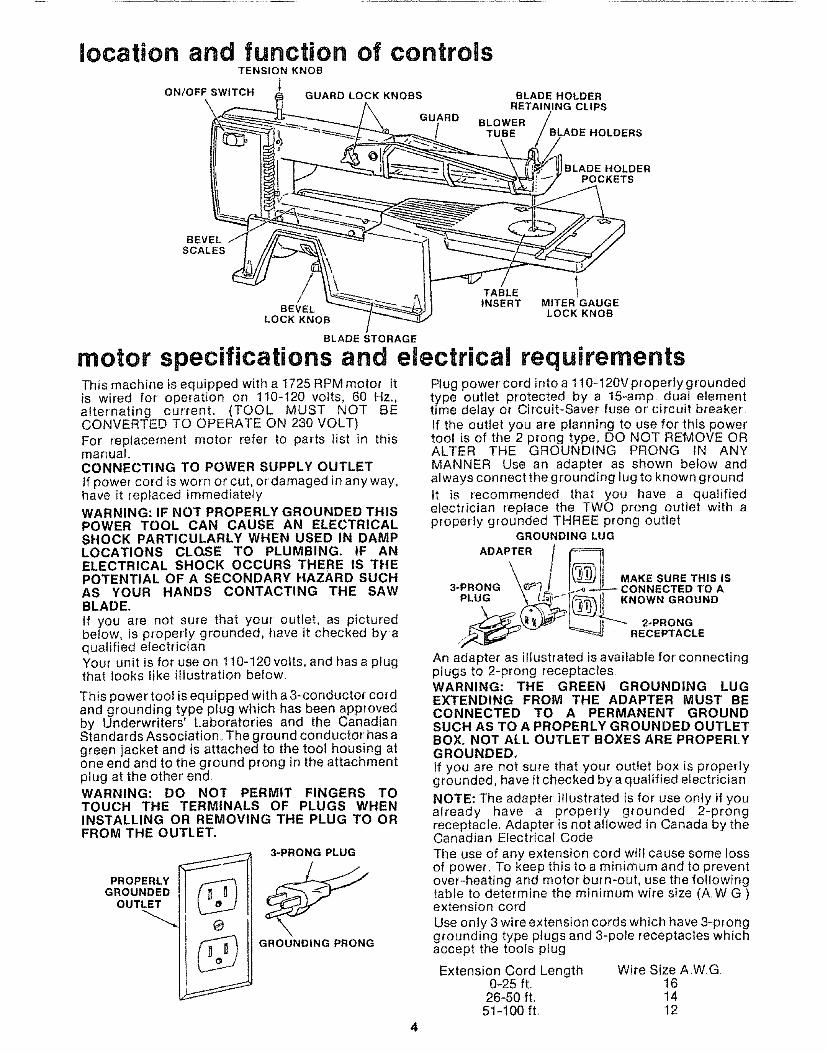
location and function of controlsTENSION KNOB
ON/OFF SWITCHGUARD LOCK KNOBS BLADE HOLDER
RETAINING CLIPS
GUARD BLOWER
TUBE ]OLDERS
BLADE HOLDERPOCKETS
BEVELSCALES
BEVELLOCK KNOB
TABLE I
INSERT MITER GAUGELOCK KNOB
BLADE STORAGE
motor specifications and electrical requirementsThis machine is equipped with a 1725 RPM motor itis wired for operation on 110-t20 volts, 60 Hz.,alternating current. (TOOL MUST NOT BECONVERTED TO OPERATE ON 230 VOLT)For replacement motor refer to parts list in thismanual.CONNECTING TO POWER SUPPLY OUTLETIf power cord is worn or' cut, or damaged in any way,have it replaced immediatelyWARNING: IF NOT PROPERLY GROUNDED THISPOWER TOOL CAN CAUSE AN ELECTRICALSHOCK PARTICULARLY WHEN USED IN DAMPLOCATIONS CLOSE TO PLUMBING. IF ANELECTRICAL SHOCK OCCURS THERE IS THEPOTENTIAL OF A SECONDARY HAZARD SUCHAS YOUR HANDS CONTACTING THE SAWBLADE,If you are not sure that your outlet, as picturedbelow, is properly grounded, have it checked by aqualified efectricianYour unit is for use on 110-120volts, and hasa plugthat looks like illustration below
This power tool is equipped with a 3=conductor cordand grounding type plug which has been approvedby Underwriters' Laboratories and the CanadianStandards Association.. The ground conductor' has agreen jacket and is attached to the tool housing atone end and to the ground prong in the attachmentplug at the other' endWARNING: DO NOT PERMIT FINGERS TOTOUCH THE TERMINALS OF PLUGS WHENINSTALLING OR REMOVING THE PLUG TO ORFROM THE OUTLET.
3-PRONG PLUG
PROPERLYGROUNDED
OUTLET
GROUNDING PRONG
Plug power cord intoa 110-120Vproperlygroundedtype outlet protected by a 15-amp dual elementtime delay or Circuit-Saver fuse or circuit breakerIf the outlet you are planning to use for tMs powertool is of the 2 prong type, DO NOT REMOVE ORALTER THE GROUNDING PRONG tN ANYMANNER Use an adapter as shown below andalways connect the grounding lug to known groundIt is recommended that you have a qualifiedelectrician replace the TWO prong outlet with aproperly grounded THREE prong outlet
GROUNDING LUG
ADAPTER
MAKE SURE THIS IS3-PRONG TO A
PLUG KNOWN GROUND
2*PRONGRECEPTACLE
An adapter as illustrated is available for connectingplugs to 2-prong receptaclesWARNING: THE GREEN GROUNDING LUGEXTENDING FROM THE ADAPTER MUST BECONNECTED TO A PERMANENT GROUNDSUCH AS TO A PROPERLY GROUNDED OUTLETBOX. NOT ALL OUTLET BOXES ARE PROPERLYGROUNDED.If you are not sure that your outlet box is properlygrounded, have it checked by a qualified electricianNOTE: The adapter illustrated is for use only if youalready have a properly grounded 2-prongreceptacle. Adapter is not allowed in Canada by theCanadian Electrical CodeThe use of any extension cord will cause some lossof power. To keep this to a minimum and to preventover-heating and motor burn-out, use the followingtable to determine the minimum wire size (AWG)extension cordUse only 3 wire extension cords which have 3-pronggrounding type plugs and 3-pole receptacles whichaccept the tools plug
Extension Cord Length Wire Size AWG0-25 ft. 16
26-50 ft. 1451-100 ft, 12

contentsPOWER TOOL WARRANTY ................... 2
GENERAL SAFETY INSTRUCTIONSFOR POWER TOOLS ........................... 2
ADDITIONAL SAFETY INSTRUCTIONSFOR SCROLL SAW .............................. 3
MOTOR SPECIFICATIONS ANDELECTRICAL REQUIREMENTS ............... 4
UNPACKING AND CHECKING CONTENTS ,, 5ASSEMBLY
Assembling Steel Legs ........................ 6Mounting Scroll Saw on Leg Set ............. 7Mounting Scroll Saw to Workbench ........... 7Mounting Scroll Saw to Mounting Board .... 8Adjusting Guard ........................... 8Installing Miter Lock Knob ..................... 8Blade Installation and Tensioningfor Plain-End and Pin Type Blades .......... 9
To Install/Tension Plain End Blades ........ 9Adjusting Insert To Table ................ t0To Install/Tension Pin Type Blades .......... tlTo Remove Plain-End or Pin Type Blades., 11Adjusting the Blade Square to Table ........ 13Installation of Bevel Scales ................ 14
unpacking and checking
_1 COMBINATION SQUARE
GETTING TO KNOW YOUR SCROLL SAWTension Control Knob .................. 15Guard Lock Knobs ............................... 15Guard ...................................... 15Blower Tube .................................. 15Blade Holder Retaining Clips ............. 15Blade Holders ................................ 15Blade Holder Pockets ....................... 15Miter Gauge Lock Knob ................... 15Table Insert ................................ 15Blade Storage ................................... 15Bevel Lock Knob ............................... !5Bevel Scales .................................. 15On-Off Switch .................................. 15Blade Storage .................................. 16
BASIC SCROLL SAW OPERATIONSawing/Scrolling ............................. 17Bevel Setting/Cutting ......................... 17Use of Miter Gauge-Crosscutting .......... 18Use of Miter Gauge-Ripping ............... 18
MAINTENANCE .................................. 18RECOMMENDED ACCESSORIES ............... 19TROUBLESHOOTING ....................... 19REPAIR PARTS ................................ 20
contentsTOOLS NEEDED
7/16" WRENCH
3/4" WRENCH
Model 113 207600 Scroll Saw is shipped complete inone carton but DOES NOT INCLUDE Steel LegsModel 113,,207650 Scroll Saw is shipped complete inone carton and INCLUDES Steel LegsSeparate all parts from packing materials and checkeach item with illustration and "Table of LooseParts", Make certain all items are accounted forbefore discarding any packing materialIf any parts are missing, do not attempt to assemblethe Scroll Saw, plug in the power cord, or turn theswitch on until the missing parts are obtained andinstalled correctlyWipe the base with a clean, dry clothWARNING: FOR YOUR OWN SAFETY, NEVERCONNECT PLUG TO POWER SOURCE OUTLETUNTIL ALL ASSEMBLY STEPS ARE COMPLETE,AND YOU HAVE READ AND UNDERSTAND THESAFETY AND OPERATIONAL INSTRUCTIONS,.
1
5
3
2
DRAW LIGHTLINE ON 8CARDALONG THIS EDGE
MEDIUM SCREWDRIVER
COMBINATION SQUARE MUST BE TRUE
_. STRAtGHT EDGE OFA BOARD 314' THICK
_'" BEPERFECTLY STRAIGHT
Item1
_2345
SHOULD BE NO GAP OR OVERLAP HERE WHENSQUARE IS FLIPPED OVER IN DOTTED POSITION
A
A
Table 0f Loose Parts Qty.Scroll Saw ............................ 1Blade Pack (containing 3 blades) ..... !Miter Gauge ........................... !Owner's Manual .................... 1Bag Assembly Part #66031 ............Containing the following parts:Holder, Blade ..................... 4Clip, Blade ........................... 4Key, Switch ............................... 1Knob ................................. 1Wedge, Rip Fence ............... 1Blade Holder Key .................... 2Wrench, Hex "L"3f32 ............. 1Scale, Bevel ......................... 2Insert, Table ............................ IScrew Soc Set t0-32 x 1/4 ........ 4Washer 13/64 x 5/8 x 1/32 ........ t*Nuts, Hex 1t4-20 .................. 4*L0ckwasher 1/4 ................. 4*Bolts, Carriage 1/4-20 x 2-1/2 ....... 4*Bumper, Rubber ..................... 4*Washer 17164 x 314 x 1t16 ....... 4
Z_C0ntained in separate bag inside loose parts bag #66031
"Moun_ing Hardware for workbench or mounting board

Item Description Qty,1 Screw, Serrated Truss Hd. 114-20 x 5/8. 242 Le .............................. 43 Stilfener, Side ........... :i,:i,ii: 24 *Lockwasher, Ext 114 .................... 245 *Nut, Hex 1t4-20 ........................ 246 Stiffener, End .............................. 27 *Nut, Hex 112-13 ........................ 88 Foot, Leveling 49 *Washer17/641b_iiiiiiill iiiiiii, ii 4I0 Screw Hex Hd 1/4-20 x 1-1/4 ........ 4
"Parts contained in Loose Parts Bag No 66037
1 2\
45
_/10654
39
2 !
assembly
SPECIAL NOTE: It is normal for this scroll saw tovibrate during operation. For this reason the scrollsaw MUST be fastened down securely to a leg set orworkbench during operation.
This Leg Set is included with Model No 113,207650only,NOTE: For illustrative purposes, the Scroll Saw isshown mounted on the Craftsman Catalog No 9-22239 Steel Leg Set
FOR LEG SET
ASSEMBLING STEEL LEGS1_ insert the Truss Head Screws through the holes
in the legs, then through the holes in thestiffeners, MAKE SURE THE SCREWS GOTHROUGH THE HOLES iN THE SIDESTIFFENERS MARKED "X"
2 Install Iockwashers and screw on the nuts, butdonot tighten until completely assembled
3 Install leveling feet as shown, To level Leg Set,loosen nut on inside of leg and turn nut on outsideto raise or' lower feet, Adjust all four levelers, ifnecessary, and then tighten nuts on inside of leg
NOTE: These levelers are not intended for heightadjustment
ENDSTIFFNER
SIDE STIFFNER
SCREWS THROUGHHOLES MARKED "X"
1/2 IN, HEX NUTS
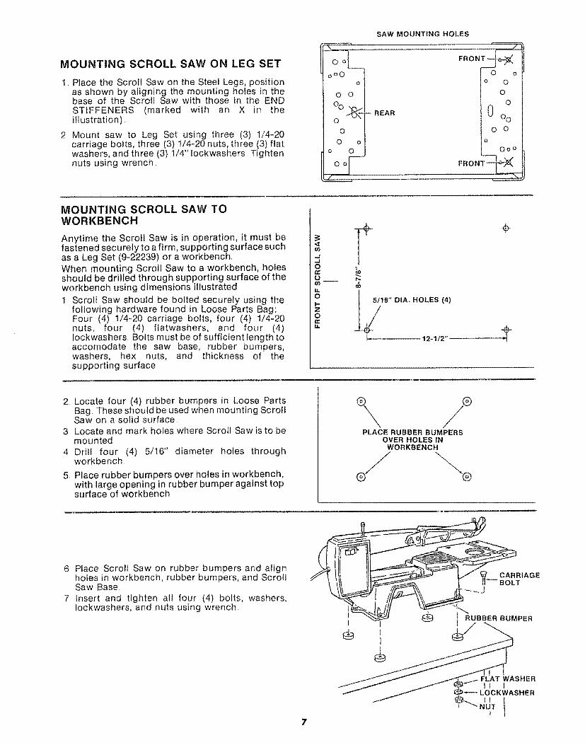
MOUNTING SCROLL SAW ON LEG SET
1 Place the Scroll Saw on the Steel Legs, positionas shown by aligning the mounting holes in thebase of the Scroll Saw with those in the ENDSTIFFENERS (marked with an X in theillustration)
2 Mount saw to Leg Set using three (3) 1/4-20carriage bolts, three (3) I/4-20 nuts, three (3)flatwashers, and three (3) 1/4" Iockwashers Tightennuts using wrench
SAW MOUNTING HOLES
oOO
o
oo
%O _-- REAR
o
o oo o
S
/
O oo O
O
O
0 Oo
o o
0
0oO
FRONT-_::_
MOUNTING SCROLL SAW TOWORKBENCH
Anytime the Scroli Saw is in operation, it must befastened securely to a firm, supporting surface suchas a Leg Set (9-22239) or a workbenchWhen mounting Scroll Saw to a workbench, holesshould be drilled through supporting surface of theworkbench using dimensions illustrated! Scroll Saw should be bolted securely using the
following hardware found in Loose Parts Bag:Four (4) 1/4-20 carriage bolts, four (4) 1/4-20nuts, four (4) flatwashers, and four (4)fockwashers, Bolts must be of sufficient length toaccomodate the saw base, rubber bumpers,washers, hex nuts, and thickness of thesupporting surface
.J_lo
Of,/)_
ol-Zo
___5/16" D1A. HOLES (4)
12-1/2"
2 Locate four (4) rubber bumpers in Loose PartsBag These should be used when mounting ScrollSaw on a solid surface
3 Locate and mark holes where Scrot{ Saw is to bemounted
4 Drill four (4) 5/16" diameter holes throughworkbench
5, Place rubber bumpers over holes in workbench,with large opening in rubber bumper against topsurface of workbench
\ /PLACE RUBBER BUMPERS
OVER HOLES INWORKBENCH
6 Place Scroll Saw on rubber bumpers and alignholes in workbench, rubber bumpers, and ScrollSaw Base,
7 insert and tighten all four (4) bolts, washers,Iockwashers, and nuts using wrench
_ CARRIAGEBOLT
II RUBBER BUMPER

assemblyMOUNTING SCROLL SAW TOMOUNTING BOARD
An alternate method of mounting is to fasten ScrollSaw to a mounting board The board should be ofsufficient size to avoid tipping of saw while in use.Any good grade of plywood or chipboard with a 3/4"minimum thickness is recommended._1 Follow instructions for mounting to a workbench,
substituting a board 12"x 24" minimum size andusing 1/4 inch fiat head screws, Iockwashers, and
.e
J
24 _ ....
__ COUNTER SINK
FROM BOTTOMOF MOUNTINGBOARD
p.
16" DIA, HOLES{4)
"_----_ 12-1/2 =[
hex nuts, Screws must be of sufficient length toaccomodate saw base, rubber feet, washers, hexnuts, and thickness of supporting boardNOTE: Holes must be counter sunk so screwheads are flush with bottom surface of supportingboardLocate, mark, and drill holes through mountingboard, and install screws, iockwashers, and nutsTighten with wrench
ii ii llll ii lllll ii ii, ,ll,i i
3. Securely clamp board to workbench using Cclampsr
NOTE: Supporting surface where Scroll Saw ismounted should be examined carefully aftermounting to insure that no movementduring use can result, if any tipping orwalking is noted, secure workbench, legs, orsupporting surface before operating ScrollSaw.
GUARDLOCK KNOBS
ADJUSTING GUARD
The Scroll Saw is shipped with a guard arid lockknobs installed1 Adjust guard by loosening the two (2) guard lock
knobs and raising guard to desired height abovetable Tighten guard lock knobs by hand.
2 Guard should be against top of workpiece toprovide additional control, but permit movementof workpiece, flat on table.
GUARD
WORKPIECE
L
INSTALLING MITER LOCK KNOB
1 Locate one (1) miter gauge lock knob, one (1)13/64 x 5/8 x 1/32 washer, and one (1) wedgeamong loose parts
2. Insert wedge into tapered recess next to frontmiter slot
3 Install washer and knob from underside of table,by engaging knob into wedge.. Tighten knob byhand
NOTE: A miter gauge is included with the ScrollSaw With the wedge locking feature, theoperator can use the miter guage to performripping as well as miter and crosscuts.
MITER GAUGE
WEDGE
1{t
WASHER
MITER GAUGE,__
LOCK KNOB _J_
MITER GAUGE

BLADE DNSTALLATUON ANDTENSIONnNG FOR PLAnN-ENDOF{ PRN TYPE BLADES
NOTE: Included with the scroll saw are three 5"blades. This saw can accommodate 5" to 6" plain-end blades, and 5" pin type blades.
'TO INSTALL/TENSION PLAIN-ENDBLADES:
WARNING: FOR YOUR OWN SAFETY, TURNSWITCH "OFF", REMOVE KEY AND REMOVEPLUG FROM POWER SOURCE OUTLET BEFOREREMOVING OR INSTALLING SAWBLADE.NOTE: Use blade holder pockets to verify correctblade length and positioning
1 Locate four (4) blade holders, four (4) 10-32 x 1/4set screws, one (1) blade, four (4) blade clips, andone (1) set screw wrench among loose parts Two(2) extra blade holder assemblies are provided forquick and convenient changing of blades,
2 Insert one (1) blade clip into each blade holder bypushing clip through holder until it snaps intoplace catching upper ledge. Insert one 10-32 x 1/4set screw into each blade holder
3 insert btade into one holder by pushing short sideof blade clip towards set screw, installing blade,and releasing side of blade clip Place holder intoblade holder pocket in table (set screw sideupward) and check for proper extension squaringblade to opposite blade holder pocket centerpoint Tighten set screw with wrench provided,
4. Insert blade into other holder (as describedabove) Place both holders in pockets in table toachieve proper spacing and tighten other setscrew
5 Place holder assembly in table insert hole; makesure the teeth are pointing downward.
BLADE
SHORT SIDE
BLADE CLIP
BLADE HOLDERSIN BLADE
HOLDER POCKETS
6 Set notches in blade holders into slots inside upperand lower arm end caps The blade holders provideslots for orientating biade in any 90° position.
NOTE: Blade holders do not touch the retainer clips afterbeing properly installed The purpose of the retainerclips is to deflect the blade holders if the blade breaks
UPPER ARMEND CAP
SLOT INEND CAP
NOTCHINBLAOEHOLDER
9

assembly
7 Locate table insert among loose parts and installin table by sliding the insert in place from back tofront of blade, aligning rear tab on back of insert,and pushing downward on front of insert
TABLEINSERT
t'l
ADJUSTING INSERT TO TABLE
if insert is higher than table top, adjust insert bytapping lightly with hammer at each tab locationuntil insert is flush with table topIf insert is lower than table top, adjust insert byslightly bending down all four tabs with a needlenose pliers
TENSIONING THE BLADE-To apply the proper tension to the blade after bladeand holders are securely in place, turn the tensionknob clockwise BY HAND until tight, (5 fullrevolutions with a wide blade; up to 7 fullrevolutions with a narrow blade) DO NOT use anytype of mechanical device or tool on tension knobAs tension is being applied, recheck the aNgnmentof the blade holder notch in the end cap slotTo check blade tension _push thumb against sideofthe blade in the middle Blade should move onlyslightly with moderate pressureNOTE: Blades tend to break more easily with toolittle tension than with too much tensionTO CHECK BLADE INSTALLATION-With blade properly installed and tensioned, placefiat-head screwdriver in motor siot and rotatemanually by turning screwdriver to check correctinstallation and clearance of the blade,
TENSIONING TENSION KNOB
BLADE
10
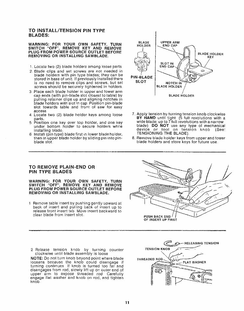
TO INSTALL/TENSION PIN TYPEBLADES:
WARNING: FOR YOUR OWN SAFETY, TURNSWITCH ='OFF", REMOVE KEY AND REMOVEPLUG FROM POWER SOURCE OUTLET BEFOREREMOVING OR INSTALLING SAWBLADE,
t Locate two (2) blade holders among loose parts2 Blade clips and set screws are not needed in
blade holders with pin type blades; they can bestored in base of unit. If previously installed thereis no need to remove clips and screws, but setscrews should be securely tightened in holders
3 Place each blade holder in upper and lower armcap ends (with pin-blade slot closest to table) bypulling retainer clips up and aligning notches inblade holders with slot in cap Position pin-bladeslot towards table and front of saw for easyaccess
4 Locate two (2) blade holder keys among looseparts.
5 Position one key over top holder, and one keyunder bottom holder to secure holders whileinstalling blade.
6 Install (pin type) blade first in lower blade holder,then in upper blade holder by sliding pin into pin =Made slot
BLADEHOLDER
l
PIN-BLADESLOT
UPPER ARMEND CAP
BLADE HOLDERKEY
BLADE HOLDER
7, Apply tension by turning tension knob clockwiseBY HAND until tight (5 full revolutions with awide blade; up to 7 full revolutions with a narrowblade) DO NOT use any type of mechanicaldevice or tool on tension knob (See:TENSIONING THE BLADE),
8, Remove blade holder keys from upper and lowerblade holders and store keys for future use
TO REMOVE PLAIN-END ORPIN TYPE BLADES
WARNING: FOR YOUR OWN SAFETY, TURNSWITCH "OFF", REMOVE KEY AND REMOVEPLUG FROM POWER SOURCE OUTLET BEFOREREMOVING OR INSTALLING SAWBLADE.
Remove table insert by pushing gently upward atback of insert and pulling back of insert up torelease front insert tab Move insert backward toclear blade from insert slot PUSH BACK END
OF INSERT UP FIRST
2 Release tension knob by turning counterclockwise until blade assembly is loose
NOTE: Do not turn knob beyond point where bladeloosens because the knob could disengage ifturning continues tf knob is turned too far anddisengages from rod, slowly tilt up on outer end ofupper arm to expose threaded rod Carefullyengage flat washer and knob on rod, and tightenknob
TENSION KNOB,_- --_ -
THREADED ROD__R _ l
11

assembly
3. For plain-end blades, remove blade holders (withblade installed) from retainer clips by putlingclips away from blade holders. Pull out upper andIowe_ blade holders Ptace blade ho(der' assemblyin blade holder pockets with set screw sideupward
4 Use set screw wrench to remove set screws inblade holders, and remove blade
BLADE HOLDERS ///J " _'
HOL' .% ETS,,I,,--./
5. For pin type blades, place blade holder keys asshown on blade holders before releasing tension
6 After blade tension is released, pull blade out ofupper and lower blade holders, remove bladeholder keys and blade holders
BLADEHOLDER
PIN-BLADESLOT
UPPER ARM
SLOT I_!J _
BLADE HOLDER
/BLADE HOLDER
12

ADJUSTING THE BLADE SQUARETO TABLE
WARNING: FOR YOUR OWN SAFETY, TURNSWITCH "OFF", REMOVE KEY AND REMOVEPLUG FROM POWER SOURCE OUTLET.
1, WITH BLADE INSTALLED AND TENSIONEDplace combination square on side of blade,Guard prevents placing square directly againstblade, so gauge squareness of blade to table byviewing from side of saw,,
GUARD
BLA[
COMBINATIONSQUARE
HOUSING
2 If an adjustment is necessary, foosen four (4) hexbolts located at back of lower arm on saw using7/16" wrench. Align blade square to table bytilting housing forward or backward, andretighten all four (4) bolts
NOTE: Make certain the blade is centered in theinsert opening Readjust if necessary byloosening four hex head bolts and movinghousing to center the blade Retighten bolts
HEX HEAD BOLTS
3 Place square in front of blade Guard preventsplacing square directly against blade, so gaugesquareness of table to blade by viewing from frontof saw
4 If an adjustment is necessary, loosen bevel lockknob located under base and rotate housingslightly to align blade to combination squareTighten bevel lock knob
JBEVEL LOCK KNOB
HOUSING
BEVELLOOK
NOB
BLADE _
CO ,¢2#,ON
F
13

assembly
INSTALLATION OF BEVEL SCALES
1 With blade installed and tensioned, Iocatetwo (2)bevel scales among loose parts
2 Locate slit in paper backing on back side of scale.Remove backing on the zero end of scale.
3 While holding scale by the end still protected bythe backing, lightly position unprotected end inthe scale recess and slide it under the indicatorAlign the zero mark with the indicator and pressthe scale to the base.
PEEL OFF THIS PIECE OF SCALE BACKING FIRST
(2ND SCALE POSIT!ON}
RECESSIN BASE LINE UP "0" MARK WITH INDICATOR
=[lllUil,llllll=U=1=k JJ
4. Loosen bevel lock knob located under- the baseand tilt head away from scale
5 Fold scale back and remove remaining paperbacking. Press entire scale against base Smoothout any wrinkles or air bubbles.
6 Repeat on opposit# side
TILT HEAD TO CLEAR SCALE
BEVEL LOCK KNOB
14

getting to know your scrota saw
13ON/OFFSWITCH
I
TENSION KNOB 2\ GUARD LOCK
KNOBS 3GUARD
5BLADE HOLDER
4 RETAINING CLIPBLOWER 6
TUBE BLADE HOLDERS
7BLADE HOLDER
POCKETS
12BEVEL
SCALES
11BEVEL
LOCK KNOB10
BLADE STORAGE
, TTABLE INSERT 8
MITERLOCK KNOB
1. TENSION KNOB . . . Tightening the knob(clockwise) wilt increase the tension on theblade Loosening it (counter clockwise) wiltdecrease the tension
2, GUARD LOCK KNOBS... Loosening the knobswill allow the guard to be adjusted to the properworking height for the thickness of theworkpiece
3. GUARD,,, Provides added control of workpieceby being set directly against thickness ofmaterial
4. BLOWER TUBE . , ° Clears pattern lines onworkpiece by blowing off sawdust particleswhich can accumulate while cutting. Tube ismounted directly behind the blade on the guard,and it operates whenever saw is on
5. BLADE HOLDER RETAINING CLIPS... Aid inpositioning, retaining, and releasing bladeholders
6. BLADE HOLDERS ..o Retain and position theblade
7, BLADE HOLDER POCKETS... Helpoperator toaccurately align, position, and tighten blade inblade holders by securing holders during bladeinstallation
8. MITER GAUGE LOCK KNOB o o , Turning theknob tightens wedge in miter slot to aIlow mitergauge to be securely locked in either of the twointersecting miter slots Several types of cutscan be made from various miter gauge positions
9, TABLE INSERT...Removes for clearance andviewing during blade assembly installation, andlocks in table while sawing
10,
11.
12.
13.
BLADE STORAGE.,, Space provided in the sawbase for extra blades, holders, and set screwwrenchBEVEL LOCK KNOB... Loosening knob allowsblade and housing assembly to tilt up to 45°right or left for bevel cutsBEVEL SCALES.., Shows degree blade is tiltedfor bevel cuttingON-OFF SWITCH... The On-Off Switch has alocking feature. THIS FEATURE 1S INTENDEDTO PREVENT UNAUTHORIZED ANDPOSSIBLY HAZARDOUS USE BY CHILDRENAND OTHERS1 lnsert Key into switchNOTE: Key is made of yellow plastic
KEY
@KEY
YELLOW PLASTIC I
15

2 To turn machineon, placefinger underswitchleverand pullendof switchout
\
3. To turn machine OFF... PUSH lever in.NEVER LEAVE THE MACHINE UNATTENDEDUNTIL IT HAS COME TO A COMPLETE STOP,
PUSH
4 To lock switch in OFF position .. hold switch INwith one hand... REMOVE key with other hand.WARNING: FOR YOUR OWN SAFETY, ALWAYSLOCK THE SWITCH "OFF" WHEN MACHINE ISNOT IN USE... REMOVE KEY AND KEEP IT IN ASAFE PLACE.., ALSO. _. tN THE EVENT OF APOWER FAILURE (ALL OF YOUR LIGHTS GOOUT) TURN SWITCH OFF... REMOVE THE KEYAND STORE IT REMOTE FROM THE SCROLLSAW. THIS WILL PREVENT THE MACHINEFROM STARTING UP AGAIN WHEN THEPOWER COMES BACK ON.
HOLD\
PULL
BLADE STORAGE
Extra blades & blade holders are included with thescroll saw See illustration for location of storage forblades and holders, and also storage for set screwwrench

basic scronHsaw operationNOTE: Make certain set screws in blade holders aretight prior to each use of the scroll sawWARNING: NEVER OPERATE WITHOUT TABLEINSERT IN PLACE°
This scroll saw accepts a wide variety of bladewidths and thicknesses: 5" to 6" length plain endtype blades and 5" length pin type blades The bladesize (thickness and width) and the number of teethper inch are determined by the type of material andthe smallest radius being cutNOTE: Use wider blades to achieve straightest cuts
A scroll saw is basically a "curve cutting" machine Itcan also be used for straight-line cutting operationssuch as cross cutting, ripping, mitering, beveling,and compound cutting.Using the proper blade for the material andthickness being cut will help the operator to followpattern lines. (Use wider blades to achieve thestraightest cuts ) Blade teeth should always pointdownWhen a blade is dull, or when insufficient bladetension is being used, the blade may have atendency to twist or breakTo minimize blade breakage and to produce moreaccurate results, be sure the blade is not forced intothe workpiece. Too much pressure should not beapplied on the wood as it is fed into the blade.Steady, even pressure will produce more uniform,cleaner cutting with less blade breakage.Loosen blade tension knob when scroll saw is not inuse.. Follow procedure to tension blade before use.
The scroll saw has the capability of inside cutting(piercing). Pin-type blades are recommended wheninside cutting as the best type of blade to use formaximum performance Drill an over-sized hole inscrap section of workpiece Locate two (2) bladeholder keys among loose parts Position each keyover one installed blade holder to secure holderwhile installing blade through workpiece. Releasetension knob (see BLADE INSTALLATION-GETTING TO KNOW YOUR SCROLL SAW)Remove blade, and place workpiece on table withdrilled hole aligned over blade slot in insert. Replaceblade, sliding it through drilled hole and insert slot.Reinstall blade in lower and upper blade holders.Retighten tension knob (see BLADE
BEVEL SETTING/CUTTING
WARNING: TO AVOID _RUNNING THE MITERGAUGE INTO THE GUARD, ALWAYS SET THEBEVEL ANGLE TO THE RIGHT AS SHOWNBELOW,
INSTALLATION-GETTING TO KNOW YOURSCROLL SAW) Remove two (2) blade holder keysand store for future use
Plain-end blades can be used for inside cutting.Follow the procedure for pin-type blades, andloosen set screws in upper and lower blade holdersusing set screw wrench When installing blade inblade holders, tighten set screws with wrenchUse caution when cutting off material which isirregular in cross section which could pinch theblade before the cut is completed A piece ofmolding for example must lay flat on the table andnot be permitted to rock while being cut
Use caution when cutting off round material such asdowel rods, or tubing They have a tendency to rollwhile being cut causing the blade to "bite" Alwaysuse a "V" block, or clamp round material to a miter
SAWING/SCROLLING
1 Adjust the guard to just contact the top of theworkpiece
2 Use both hands while feeding the work into theblade Hold the workpiece firmly against thetable Use gentle pressure, and do not force thework, but allow the blade to cut
3 Avoid putting side loads on the blade duringcutting to keep cut square to table
NOTE: When very sharp curves are to be cut, narrowblades should be used Remove blade clips whenusing narrow blades
Loosen bevel lock knob and tilt housing of saw tothe desired angle degree by reading bevel scalesAdjust the guard to just contact the top of theworkpiece Perform bevel cuts by feedingworkpiece into blade without a guide or using themiter gauge HOUSING
17
BEVELLOCK KNOB

basic scroll saw operationUSE OF MITER GAUGE -CROSS CUTTING
WARNING: TO AVOID WORK INSTABILITY ORRUNNING THE MITER GAUGE INTO THE BLADE,TURN THE MITER GAUGE FACE TOWARD THEBLADE AND USE THE MITER SLOTACROSSTHETABLE FRONT FOR ALL ANGLES OVER 55° . USETHE SLOT PARALLEL TO THE SAW ARM FOR ALLOTHER ANGLES°
To perforrn a miter or crosscut on the scroll saw, donot use miter gauge lock knob and wedge (Storeknob and wedge for future use) Adjust the guard tojust contact the top of th,_. _.',orkpiece The miter slotrunning pa,.,liel to saw arm sftould be used whenblade teeth are in th,e fl unt position Hoid workpieceagainst face of miter gauge, and cut off board atdesired dimension by pushing miter gauge andboard forward.
MITER GAUGEFACE
MITER GAUGE
WORKPIECE
NOTE: Use wider blades to achieve straight cuts
WARNING: NEVER LEAVE THE MITER GAUGELOOSE ON THE SAW. VIBRATION MAY CAUSEHAZARDOUS MOVEMENT.
USE OF MITER GAUGE - RIPPING
To perforrn a rip cut on the scroll saw, use the mitergauge lock knob and wedge to secure the mitergauge in the slot The miter slot runningperpendicular to the saw arm should be used whenripping boards less than 18 inches in length andwhen the blade teeth are in the front position, Themiter slot running parallel to the saw arm should beused for ripping longer boards and when blade teethare in the side position, Ad ust the guard to justcontact the top of the workpiece, Tighten mtergauge lock knob at desired setting and feedworkpiece into blade using miter gauge faceasa ripfence. Miter gauge head must be oriented andlocked at 0° miter angle position to perform a ripcut
NOTE: Use wider blades to achieve straightest cuts,.
,i,,,
maintenanceWARNING: FOR YOUR OWN SAFETY, TURNSWITCH "OFF", REMOVE KEY AND REMOVEPLUG FROM POWER SOURCE OUTLET BEFOREMAINTAINING OR LUBRICATING YOUR SAW.
GENERAL
Keep your Scroll Saw clean,Do not allow pitch to accumulate on the table, tabIeinsert, blade or biade holders Clean them withCraftsman Gum and Pitch RemoverApply a thin coat of automobile-type wax on thetable so the wood slides easily while cutting Alsoapply wax to the inside surfaces of the trunnion(base)
i
ARM PIVOTBEARINGS

MOTOR
Frequently vacuum or blow out any sawdust fromthe motorIf the power cord is worn, cut, or damaged in anyway, have it replaced immediately
LUBRICATION
Ali of the BALL BEARINGS are packed with greaseat the factory, They require no further lubrication,Lubricate arm pivot bearings occasionally with lightweight machine grade oil, or 20 weight motor oilMultFpurpose household lubricants may also beused,
RECOMMENDED ACCESSORIES
ItemLeg Set ................................... 9-22239Blades ................................ See Cata{ogCasters ....................... 9-22221 or 9-222)2
WIRING DIAGRAM
SWITCH
BLACK _ WHITEW.,TO( . ,--=t___.. CON.ECTOR t O )
,v J_-_" GROUND SCREW "_-_..,__'- MOTOR
trouble shooting
WARNING: FOR YOUR OWN SAFETY, TURN SWITCH "OFF", REMOVE KEYAND REMOVE PLUG FROM POWER SOURCE OUTLET BEFORETROUBLESHOOTING YOUR SCROLL SAW.
TROUBLE PROBABLE CAUSE REMEDY
Motor will not run.
Scroll Saw slows downwhen cutting°
Blades breaking orbending,
Blade twisted or out of line.
1 Defective On-Off switch 1Defective switch cordDefective switch box receptacle
2 Motor Defective 2
3 Cutting too fast,defective blade;mechanism jammed
1 Cutting too small a radius
2 Dull blade
1 Too little tension,, 1
2 Kink in blade caused by 2cutting too small a raduis orturning the material too fastwhen cutting
3 Blade not set far enough in 3blade holders
4 Forcing workpiece into 4blade or sideloadingblade excessively
! Blade Holders incorrectly setin arm end caps
2 Blade not square to table
Replace defective parts before using ScrollSaw again
Consult Sears Service Any attempt to repairthis motor may create a HAZARD unlessrepair is done by a qualified servicetechnician, Repair service is available at yournearest Sears Store
3 A slot has been provided in the end of themotor shaft to insert screwdriver tomanually cycle motor Unit must beunplugged from power source
1 Stop feeding, and back up to the materialslightly, until the scroll saw speeds up; usesmaller blade
2 Replace blade
Adjust tension, See "Getting To Know YourScroll Saw Tension Setting"Use correct cutting technique See "BasicScroll Saw Operation" Section
Remove blade holder assembly and reinstallblade correctly in holders See " AssemblyBlade Installation"Do not force workpiece AIfowblade to cut Avoid applyingexcessive sideload
1 Adjust blade holders -- See "AssemblyBlade Installation"
2, Adjust blade to table - See "Assembly -Adjusting the Blade Square to Table"
19

PARTS LIST FOR CRAFTSMAN 18-INCH MOTORIZED SCROLL SAWMODEL NO. 113.207600 AND 113.207650
3
63
57
55 56
4O
41
43
66
FIGURE 1
2O

PARTS LIST FOR CRAFTSMAN 18-INCH MOTORIZED SCROt.L SAWMODEL NO. 113.207600 AND 113.207650
Always order by Part Number - Not by Key Number
FIGURE 1
%_oy Part
No.
t I STD601105
2 1660153 1660164 166o055 } 660326 f 60464
7 I SJ_D551010
8 / 660219 / 66034
10 _6602411 / 6600912 / 66019
t3 ! 60527
14 66011
15I16 66029
I 17 66010I 18 66007I 19 STD54t408I 20 66014I 21 STD551012I 22 STD551231
23 60460I 24 66018} 25 809102-2
26 60129/ 27 60461
28 66036I 29 60467
30 6046631 6603532 62442
/ 33 60256
I 34 STD601103
Description
*Screw, Pan Cross Type "T"10-32 x 1/2Cover, MotorFanMotorHousing AssemblySpacer
*Washer, 13/64 x 7/16x 025Knob
Tube Assembly, UpperRetainer
CapHolder, BladeScrew, Hex Soc Half DogSet 10-32 x 1/4Clip, BladetBlade, Scroll SawWedge, Blade TensionChannel, VBearing, Flanged
"Nut, Hex Locking 8-32Counterbalance
*Washer, 17/64 x 1/2 x 1/32*Lockwasher, Internal 5/16Screw, Shoulder 5/16Guard, BladeKnobWasher, 21/64 x 1/2 x 1/32Screw, Hex Cap 5/16-18 x 2Link AssemblyRing, RetainingWasher, ,190 x 88 x 040Tube Assembly LowerSwitch, LockingKey, Switch
*Screw, Pan Cross Type "T"10-32 x 5/16
Key I PartNo, I No,
35 I STD55121036 16602537 16603038 166O3339 ISTD55120640 160459
41 ISTD600603
42i6602243 16217644 16052645 180511646 ISTD55112547 1STD5410254B 1604654_ 16338750 1660125! !6600652 16602653i6600854 ! STD53310755 STD55122556 STD52250357 6046358 6602359 6602860 2773361 6602762 STD50250263 3781864 6601365 80370966 6217067 6602068 37836
66017
66031
Description
*Lockwasher, External No 10Rod, TensionWedge, Rip FenceInsert Assembly
*Lockwasher, Internal No 6Screw, Fil Hd Type "T"10_32 x 1 3/8
*Screw, Pan Sl Type "T"6-32 x 5/16Panel, TrimKnob, Miter GaugeBolt, Carriage 1/4_20 x 2-1/2Bumper, Rubber
'Lockwasher, 1/4*Nut, Hex 1/4-20Washer, 21/64 x 47/64x 1/16KnobClip, TrunnionBaseScale, BevelBracket, Trunnion
*Bolt, Carriage 5/16-18 x 3/4Lockwasher, External 1/4
*Screw, Hex Hd 1/4-20 x 3/8SpacerPumpTubingNut, 5/16Spring
*Screw, Set 1/4-20 x I/4Relief, StrainCord with PlugConnector, WireGauge Assembly, MiterKey, Blade HolderWrench, Hex L 3/32Owner's Manual (NotIllustrated)Bag of Loose Parts (NotIllustrated)
*Standard hardware items - may be purchased locally
I" Stock Item - May be secured through the Hardware Deptof most Sears Retail Stores or Catalog Order Houses
21
PARTS LIST FOR CRAFTSMAN 18-INCH MOTORIZED SCROLL SAWMODEL NO. 113.207600 AND 113,207650
8
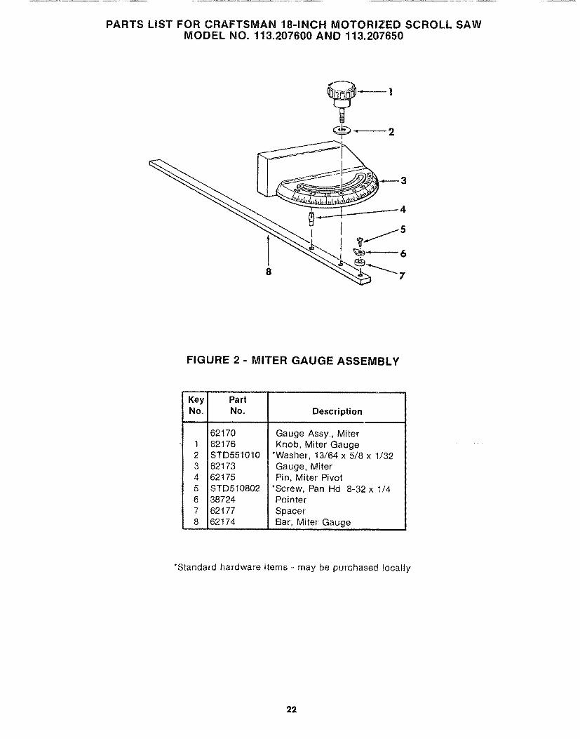
FIGURE 2 - MITER GAUGE ASSEMBLY
Key PartNo. No. Description
H, ii
12345678
6217062176STD5510106217362175STD510802387246211762174
Gauge Assy, MiterKnob, Miter Gauge
*Washer, 13/64 x 5/8 x 1/32Gauge, MiterPin, Miter Pivot
*Screw, Pan Hd 8-32 x 1/4PointerSpacerBar, Miter Gauge
*Standard hardware items - may be purchased locally
22

PARTS LIST FOR CRAFTSMAN 18-INCH MOTORIZED SCROLL SAWMODEL NO. 113.207600 AND 113.207650
4 53
| 2 '_o
\
6
o 6 5 4_tj
2 ]
2
FIGURE 3 - LEG SET FOR
MODEL 113.207650 ONLY
,,,J,l,,.
Key PartNo. No.
1 60314
23456
78
6374962554STD551225STD541025
62615
STD54125080383566037
Description ........
Screw, Serrated Truss Hd1/4-20 x 5/8LegStiffener, Side
*Lockwasher, Ext 1/4*Nut, Hex 1/4-20Stiffener, End
*Nut, Hex 1/2-13Foot, Leveling
t Bag of Loose Parts(not illustrated)
HARDWARE FOR
STD551012
STD522512
MTG. TOOL.
*Washer, 17/64 x 9/16 x 3/4*Screw, Hex Hd 1/4-20 x1 1/4
*Standard Hardware Items -- May be Purchased Locally
t Bag contains all Loose Parts for Legs
23

SERVICE
MODEL NO113.207600
SAW ONLY
MODEL NO.113.207650SAW WITH LEGS
HOW TO ORDER
REPAIR PARTS
18-iNCHMOTORIZED SCROLL SAW
Now that you have purchased your 18-inch motorized Scrolf Sawshould a need ever exist for repair parts or service, simply contactany Sears Service Center and most Sears, Roebuck and Costores° Be sure to provide all pertinent facts when you call or visit
The model number of your 18-inch motorized Scroll Saw will befound on a plate at the right hand side of the saw.
WHEN ORDERING REPAIR PARTS, ALWAYS GIVE THEFOLLOWING INFORMATION:
PART NUMBER
MODEL NUMBER113.207600 or'
113.207650
PART DESCRIPTION
NAME OF ITEM18-Inch Motorized Scroll Saw
All parts listed may be ordered from any Sears Service Centerand most Sears stores If the parts you need are not stockedlocally, your order will be electronically transmitted to a SearsRepair Parts Distribution Center for handling
Sold by SEARS, ROEBUCK AND CO., Chicago, IL. 60684 U.S.A.
Part Noo66017 Form NOo SP4701-5 Printed in US A, 11/89